Embed Size (px)
Citation preview

GRUNDFOSPRODUCT GUIDE
CR, CRI, CRN
Custom-built pumps60 Hz

Contents
2
Contents
Product dataCustom-built pumps 3Variant overview 3Performance range 4Type keys 5Codes 5How to read a curve chart 6Curve conditions 6
MotorsGeneral information 7Efficiency class 8Benefits offered by high efficiency motors 8Pump range 8NEMA TEFC Motor Efficiency Standards & Baldor Super-E Efficiency 8
Shaft seal arrangementsDouble seal (tandem) 9Double seal (back-to-back) 10Back-to-back double seal with pressure intensifier 11Back-to-back double seal with dosing pump 11Cool-Top® (high temperatures) 12
Shaft sealsShaft seal with FFKM or FXM O-ring material 14Hybrid shaft seal 15
CertificatesCertificates 16ATEX-approved CR pumps 17
MAGdriveMagnetic-drive pump (MAGdrive) 18
LiqTecLiqTecTM dry-running sensor 19
PumpsHorizontally mounted pumps 20Pumps with bearing flange 22Belt-driven pumps 24Pumps for liquid temperatures down to –40°F 26Carbon-free pumps 27Silicon-free pumps 27Pumps for pharmaceutical andbiotechnological applications 28TriClamp 28Cleaned and dried pumps 29Electropolished pumps 29
Low-NPSH pumpsLow-NPSH pumps 30Performance curves 31CR 3 31CR 5 32CR 10 33CR 15 34CR 20 35CR 32 36CR 45 37CR 64 38
4-pole versionsCR pumps with 4-pole motors 39Performance curves 40CR 1 40CR 3 41CR 5 42CR 10 43CR 15 44CR 20 45CR 32 46CR 45 47CR 64 48CR 90 49

3
Custom-built pumpsProduct data
Custom-built pumpsGrundfos offers a wide range of custom-built variants ofthe CR type range for a variety of demanding industrialapplications. Featuring superior reliability like thestandard products, the custom-built pumps meet thestrictest demands for durability and trouble-free opera-tion.
With these multistage in-line pumps, based on the well-known CR type range, Grundfos meets the customers’needs for pumps capable of handling
• high-temperature liquids
• high-viscosity liquids such as paints and varnishes
• volatile and explosive liquids and
• aggressive liquids
• special installation requirements.
The Grundfos CR range
Material versions:
• Cast iron/stainless steel, AISI 304 = CR
• Stainless steel, AISI 304 = CRI
• Stainless steel, AISI 316 = CRN
• Titanium = CRT
Pump types:
CR 1s, 1, 3, 5, 10, 15, 20, 32, 45, 64 and 90.
Pumped liquid temperature:
–40°F to +356°F.
This product guide gives an overview of some of thecustom-built solutions offered by Grundfos. If theproduct guide does not provide a solution to yourspecific pumping needs, please contact your localGrundfos company with a detailed description of yourapplication!
Variant overviewThe overview of custom-built solutions refers only tothe CR, CRI, CRN range.
The overview is divided into the following parts:
• Motors
• Shaft seals
• Pumps.
Motors
The standard range of motors meets a wide variety ofapplication demands.
For special applications or operating conditions,Grundfos offers custom-built motors such as
• explosion-proof motors for hazardous atmospheres (including ATEX approved motors)
• motors with anti-condensation heating unit for hu-mid environments
• High efficiency motors
• Motors with different enclosure class
• Oversized motors
• motors with thermal protection.
Shaft seals
Grundfos offers a wide range of special-purpose shaftseals and shaft seal arrangements for the pumping ofliquids such as
• aggressive or corrosive liquids
• particle-carrying liquids
• toxic or explosive liquids
• high-viscosity or sticky liquids
and for operating under conditions such as
• extremely high pressures
• extremely high or low temperatures.
Pumps
The pump can be custom-built for special operatingconditions and applications such as
• high inlet pressures
• high-pressure systems up to 725 psi
• horizontal mounting
• applications demanding belt-driven pumps
• pharmaceutical and biotechnological applications
• applications requiring low NPSH.
GR5
357

4
Product data Custom-built pumps
Performance range
TM0
2 83
76 5
103
4 6 8 1010 20 30 40 60 80 100100 200 300 400 600 800Q [US GPM]
60
80
100100
150
200
300
400
600
800
10001000
1500[ft]H
20
30
40
5060
80
100100
200
300
400
[m]H
11 2 3 4 5 6 8 1010 20 30 40 50 60 80 100100Q [m³/h]
60 Hz
CR 32
CR 45CR 1s CR 10
CR 15
CR 20
CR 1
CR 90
CR 64CR 5
CR 3
CRI 1CRN 1
CRI 3
CRN 3
CRI 5CRN 5
CRN 32 CRN 64
CRN 90CRN 45CRI 10
CRN 10
CRI 15CRN 15
CRI 20
CRN 20
CRI 1s
CRN 1s
4 6 8 1010 20 30 40 60 80 100100 200 300 Q [US GPM]
0
20
40
60
80[%]Eta
High-pressure range
5
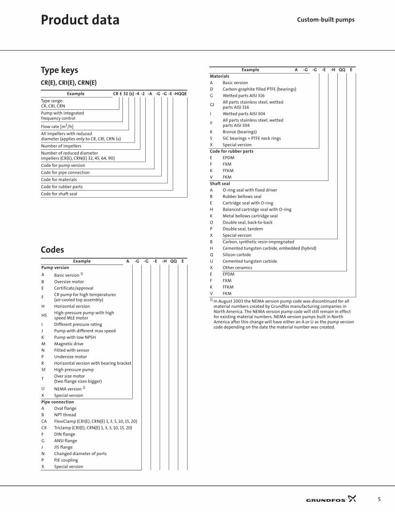
Type keysCR(E), CRI(E), CRN(E)
Codes
Example CR E 32 (s) -4 -2 -A -G -G -E -HQQE
Type range:CR, CRI, CRN
Pump with integrated frequency control
Flow rate [m3/h]
All impellers with reduceddiameter (applies only to CR, CRI, CRN 1s)
Number of impellers
Number of reduced diameterimpellers (CR(E), CRN(E) 32, 45, 64, 90)
Code for pump version
Code for pipe connection
Code for materials
Code for rubber parts
Code for shaft seal
Example A -G -G -E -H QQ E
Pump version
A Basic version 1)
B Oversize motor
E Certificate/approval
FCR pump for high temperatures(air-cooled top assembly)
H Horizontal version
HSHigh-pressure pump with high speed MLE motor
I Different pressure rating
J Pump with different max speed
K Pump with low NPSH
M Magnetic drive
N Fitted with sensor
P Undersize motor
R Horizontal version with bearing bracket
SF High pressure pump
TOver size motor(two flange sizes bigger)
U NEMA version 1)
X Special version
Pipe connection
A Oval flange
B NPT thread
CA FlexiClamp (CRI(E), CRN(E) 1, 3, 5, 10, 15, 20)
CX Triclamp (CRI(E), CRN(E) 1, 3, 5, 10, 15, 20)
F DIN flange
G ANSI flange
J JIS flange
N Changed diameter of ports
P PJE coupling
X Special version
Materials
A Basic version
D Carbon-graphite filled PTFE (bearings)
G Wetted parts AISI 316
GIAll parts stainless steel, wetted parts AISI 316
I Wetted parts AISI 304
IIAll parts stainless steel, wetted parts AISI 304
K Bronze (bearings)
S SiC bearings + PTFE neck rings
X Special version
Code for rubber parts
E EPDM
F FXM
K FFKM
V FKM
Shaft seal
A O-ring seal with fixed driver
B Rubber bellows seal
E Cartridge seal with O-ring
H Balanced cartridge seal with O-ring
K Metal bellows cartridge seal
O Double seal, back-to-back
P Double seal, tandem
X Special version
B Carbon, synthetic resin-impregnated
H Cemented tungsten carbide, embedded (hybrid)
Q Silicon carbide
U Cemented tungsten carbide
X Other ceramics
E EPDM
F FXM
K FFKM
V FKM1) In August 2003 the NEMA version pump code was discontinued for all
material numbers created by Grundfos manufacturing companies in North America. The NEMA version pump code will still remain in effect for existing material numbers. NEMA version pumps built in North America after this change will have either an A or U as the pump version code depending on the date the material number was created.
Example A -G -G -E -H QQ E
Product data Custom-built pumps
6
Product data Custom-built pumps
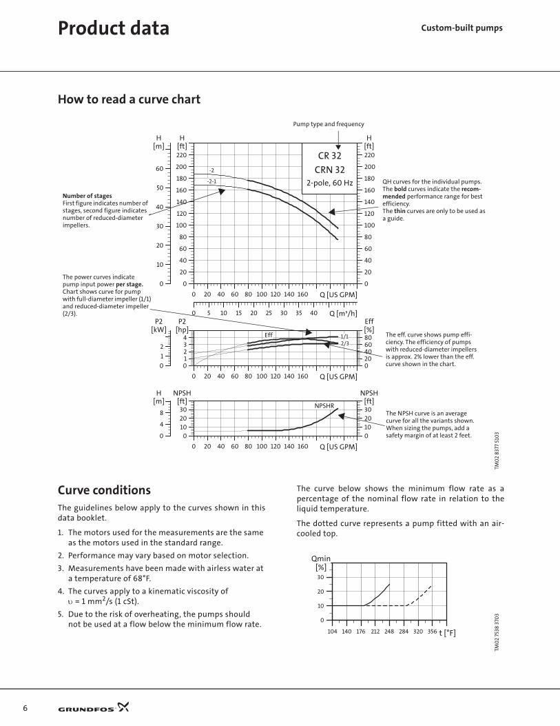
How to read a curve chart
Curve conditionsThe guidelines below apply to the curves shown in thisdata booklet.
1. The motors used for the measurements are the same as the motors used in the standard range.
2. Performance may vary based on motor selection.
3. Measurements have been made with airless water at a temperature of 68°F.
4. The curves apply to a kinematic viscosity ofυ = 1 mm2/s (1 cSt).
5. Due to the risk of overheating, the pumps shouldnot be used at a flow below the minimum flow rate.
The curve below shows the minimum flow rate as apercentage of the nominal flow rate in relation to theliquid temperature.
The dotted curve represents a pump fitted with an air-cooled top.
TM0
2 83
77 5
103
0 20 40 60 80 100 120 140 160 Q [US GPM]
0
20
40
60
80
100
120
140
160
180
200
220[ft]H
0 5 10 15 20 25 30 35 40 Q [m³/h]
0
10
20
30
40
50
60
[m]H
0
20
40
60
80
100
120
140
160
180
200
220[ft]H
CR 32
CRN 322-pole, 60 Hz-2-1
-2
0 20 40 60 80 100 120 140 160 Q [US GPM]
01234
[hp]P2
020406080[%]Eff
0
1
2
[kW]P2
Eff 1/12/3
0 20 40 60 80 100 120 140 160 Q [US GPM]
0102030
[ft]NPSH
0102030[ft]
NPSH
0
4
8
[m]H
NPSHR
Pump type and frequency
Number of stagesFirst figure indicates number of stages, second figure indicates number of reduced-diameter impellers.
The power curves indicatepump input power per stage.Chart shows curve for pump with full-diameter impeller (1/1) and reduced-diameter impeller(2/3).
QH curves for the individual pumps.The bold curves indicate the recom-mended performance range for bestefficiency.The thin curves are only to be used as a guide.
The eff. curve shows pump effi-ciency. The efficiency of pumps with reduced-diameter impellersis approx. 2% lower than the eff. curve shown in the chart.
The NPSH curve is an averagecurve for all the variants shown.When sizing the pumps, add asafety margin of at least 2 feet.
TM0
2 75
38 3
703
40 60 80 120 140 160 180 t [°F]
0
10
20
30
Qmin[%]
140 176 212 248 284 320 356104
7
Custom-built pumpsMotors
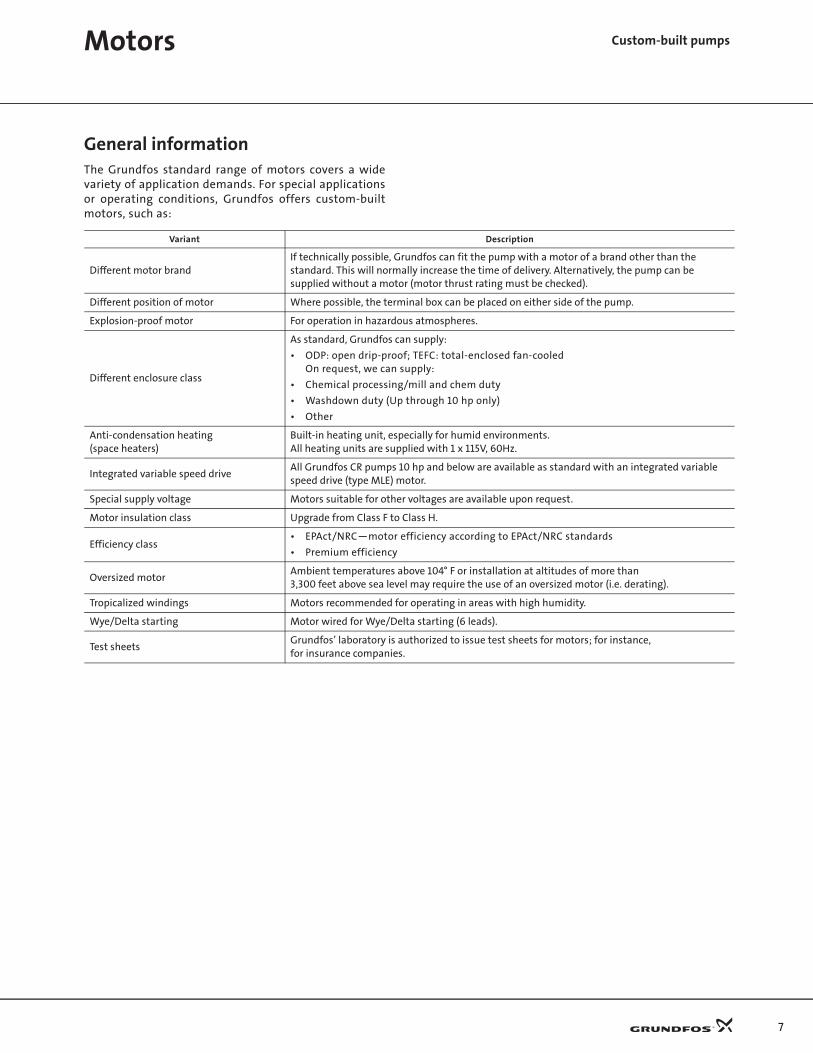
General informationThe Grundfos standard range of motors covers a widevariety of application demands. For special applicationsor operating conditions, Grundfos offers custom-builtmotors, such as:
Variant Description
Different motor brandIf technically possible, Grundfos can fit the pump with a motor of a brand other than thestandard. This will normally increase the time of delivery. Alternatively, the pump can besupplied without a motor (motor thrust rating must be checked).
Different position of motor Where possible, the terminal box can be placed on either side of the pump.
Explosion-proof motor For operation in hazardous atmospheres.
Different enclosure class
As standard, Grundfos can supply:
• ODP: open drip-proof; TEFC: total-enclosed fan-cooledOn request, we can supply:
• Chemical processing/mill and chem duty
• Washdown duty (Up through 10 hp only)
• Other
Anti-condensation heating(space heaters)
Built-in heating unit, especially for humid environments.All heating units are supplied with 1 x 115V, 60Hz.
Integrated variable speed driveAll Grundfos CR pumps 10 hp and below are available as standard with an integrated variable speed drive (type MLE) motor.
Special supply voltage Motors suitable for other voltages are available upon request.
Motor insulation class Upgrade from Class F to Class H.
Efficiency class• EPAct/NRC—motor efficiency according to EPAct/NRC standards
• Premium efficiency
Oversized motorAmbient temperatures above 104° F or installation at altitudes of more than3,300 feet above sea level may require the use of an oversized motor (i.e. derating).
Tropicalized windings Motors recommended for operating in areas with high humidity.
Wye/Delta starting Motor wired for Wye/Delta starting (6 leads).
Test sheetsGrundfos’ laboratory is authorized to issue test sheets for motors; for instance,for insurance companies.

8
Motors Custom-built pumps
Efficiency classGrundfos offers motors with Energy Efficient EPAct/NRCclass and Premium Efficiency class. When Premium Effi-ciency motors are ordered, the Baldor Super-E® motor issupplied which in most cases exceeds the NEMA PremiumEfficiency standards.
Benefits offered by high efficiency motors
• Improved efficiency (see graph below)• Lower noise level• Higher permissible ambient temperature• Longer bearing life due to reduced temperature
Pump range
Energy Efficient and Premium Efficiency motors areavailable for all Grundfos CR pumps.
NEMA TEFC Motor Efficiency Standards & Baldor TEFC Super-E Efficiency
Note: ODP Efficiency points are in table below.
Notes:
1. The term “High Efficiency” is commonly used but is not recognized in the NEMA standards (MG 1-1198, Part 12).
2. Some standard CR pump motors already meet the EPAct/NRC requirement. See the CR, CRI, CRN Product Guide.NEMA TEFC Motor Efficiency Standards & Baldor Super-E Efficiency
Pump type
CR 1s CR 1 CR 3 CR 5 CR 10 CR 15 CR 20 CR 32 CR 45 CR 64 CR 90
CR
CRI
CRN
70
75
80
85
90
95
100
1 1,5 2 3 5 7,5 10 15 20 25 30 40 50 60HP
Effi
cien
cy (%
)
TEFC EPAct/NRC TEFC Premium Eff. TEFC Super-E
HPODP TEFC
EPAct/NRC Premium Eff. Super-E EPAct/NRC Premium Eff. Super-E
1 -- 77.0 84.0 75.5 77.0 78.5
1 1/2 82.5 84.0 85.5 82.5 84.0 85.5
2 84.0 85.5 86.5 84.0 85.5 86.5
3 84.0 85.5 87.5 85.5 86.5 88.5
5 85.5 86.5 90.2 87.5 88.5 89.5
7 1/2 87.5 88.5 90.2 88.5 89.5 91.0
10 88.5 89.5 91.7 89.5 90.2 91.7
15 89.5 90.2 91.7 90.2 91.0 91.7
20 90.2 91.0 92.4 90.2 91.0 92.4
25 91.0 91.7 93.0 91.0 91.7 93.0
30 91.0 91.7 93.6 91.0 91.7 93.0
40 91.7 92.4 94.1 91.7 92.4 93.6
50 92.4 93.0 93.6 92.4 93.0 94.1
60 93.0 93.6 94.5 93.0 93.6 94.1
9
Custom-built pumpsShaft seal arrangements
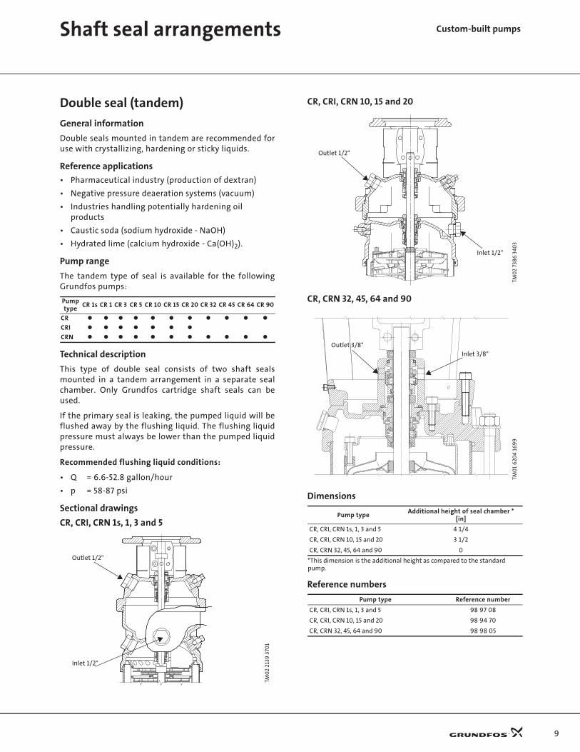
Double seal (tandem)
General information
Double seals mounted in tandem are recommended foruse with crystallizing, hardening or sticky liquids.
Reference applications
• Pharmaceutical industry (production of dextran)
• Negative pressure deaeration systems (vacuum)
• Industries handling potentially hardening oilproducts
• Caustic soda (sodium hydroxide - NaOH)
• Hydrated lime (calcium hydroxide - Ca(OH)2).
Pump range
The tandem type of seal is available for the followingGrundfos pumps:
Technical description
This type of double seal consists of two shaft sealsmounted in a tandem arrangement in a separate sealchamber. Only Grundfos cartridge shaft seals can beused.
If the primary seal is leaking, the pumped liquid will beflushed away by the flushing liquid. The flushing liquidpressure must always be lower than the pumped liquidpressure.
Recommended flushing liquid conditions:
• Q = 6.6-52.8 gallon/hour
• p = 58-87 psi
Sectional drawings
CR, CRI, CRN 1s, 1, 3 and 5
CR, CRI, CRN 10, 15 and 20
CR, CRN 32, 45, 64 and 90
Dimensions
Reference numbers
Pump type
CR 1s CR 1 CR 3 CR 5 CR 10 CR 15 CR 20 CR 32 CR 45 CR 64 CR 90
CR
CRI
CRN
TM0
2 21
39 3
701
Outlet 1/2"
Inlet 1/2"
TM0
2 73
86
340
3TM
01
620
4 16
99
Pump typeAdditional height of seal chamber *
[in]
CR, CRI, CRN 1s, 1, 3 and 5 4 1/4
CR, CRI, CRN 10, 15 and 20 3 1/2
CR, CRN 32, 45, 64 and 90 0
*This dimension is the additional height as compared to the standard pump.
Pump type Reference number
CR, CRI, CRN 1s, 1, 3 and 5 98 97 08
CR, CRI, CRN 10, 15 and 20 98 94 70
CR, CRN 32, 45, 64 and 90 98 98 05
Inlet 1/2"
Outlet 1/2"
•
• •
•
Inlet 3/8"Outlet 3/8"
10
Shaft seal arrangements Custom-built pumps
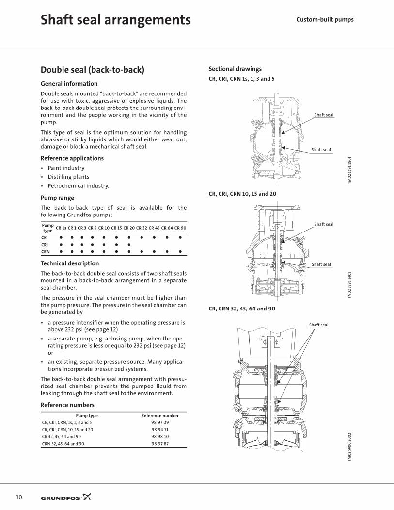
Double seal (back-to-back)
General information
Double seals mounted "back-to-back" are recommendedfor use with toxic, aggressive or explosive liquids. Theback-to-back double seal protects the surrounding envi-ronment and the people working in the vicinity of thepump.
This type of seal is the optimum solution for handlingabrasive or sticky liquids which would either wear out,damage or block a mechanical shaft seal.
Reference applications
• Paint industry
• Distilling plants
• Petrochemical industry.
Pump range
The back-to-back type of seal is available for thefollowing Grundfos pumps:
Technical description
The back-to-back double seal consists of two shaft sealsmounted in a back-to-back arrangement in a separateseal chamber.
The pressure in the seal chamber must be higher thanthe pump pressure. The pressure in the seal chamber canbe generated by
• a pressure intensifier when the operating pressure is above 232 psi (see page 12)
• a separate pump, e.g. a dosing pump, when the ope-rating pressure is less or equal to 232 psi (see page 12) or
• an existing, separate pressure source. Many applica-tions incorporate pressurized systems.
The back-to-back double seal arrangement with pressu-rized seal chamber prevents the pumped liquid fromleaking through the shaft seal to the environment.
Reference numbers
Sectional drawings
CR, CRI, CRN 1s, 1, 3 and 5
CR, CRI, CRN 10, 15 and 20
CR, CRN 32, 45, 64 and 90
Pump type
CR 1s CR 1 CR 3 CR 5 CR 10 CR 15 CR 20 CR 32 CR 45 CR 64 CR 90
CR
CRI
CRN
Pump type Reference number
CR, CRI, CRN, 1s, 1, 3 and 5 98 97 09
CR, CRI, CRN, 10, 15 and 20 98 94 71
CR 32, 45, 64 and 90 98 98 10
CRN 32, 45, 64 and 90 98 97 87
TM0
2 16
91
180
1TM
02
7385
340
3TM
02
500
0 2
00
2
Shaft seal
Shaft seal
Shaft seal
Shaft seal
•
Shaft seal

11
Back-to-back double seal with pressure intensifier
Dimensions
The dimension b is the additional height as compared tothe standard pump.
Reference numbers
Back-to-back double seal with dosing pump
Note: One dosing pump installation can supply severalpumps fitted with back-to-back double seal.
Connections are all ½".Note: Connecting pipes/hoses are not included.
Dimensions
Reference numbers
TM0
1 44
55 0
399
TM0
1 44
59 0
399
Pump typea
[in]b
[in]c
[in]
CR, CRI, CRN 1s, 1, 3 and 5 11 3/4 4 1/4 5
CR, CRI, CRN, 10, 15 and 20 12 3/4 3 1/2 5 1/2
CR, CRN 32 13 1/2 8 1/4 6
CR, CRN 45 13 3/4 9 1/2 6 1/2
CR, CRN 64 13 3/4 6 1/2 6 1/2
CR, CRN 90 14 7 1/4 6 3/4
Pressure intensifier(not available for CRT)
Material Reference number
AISI 316, FKM 98 98 92
AISI 316, EPDM 98 98 91
Pressure intensifier
Double seal
CR, CRI, CRN pump
a
b
c
tm0
1 9
09
9 1
701
Pump typeAdditional height of seal chamber *
[in]
CR, CRI, CRN 1s, 1, 3, 5 4 1/4
CR, CRI, CRN, 10, 15 and 20 3 1/2
CR, CRN 32 8 1/4
CR, CRN 45 9 1/2
CR, CRN 64 6 1/2
CR, CRN 90 7 1/4
*This dimension is the additional height as compared to the standard pump.
Dosing pump,max. 232 psi
Reference number
98 98 09
Barrier fluid
Shaft seal arrangements Custom-built pumps

12
Shaft seal arrangements Custom-built pumps
Cool-Top® (high temperatures)
General information
The unique Grundfos air-cooled top shaft seal solution isrecommended for applications involving high tempera-tures from 248°F to 356°F.
The Cool-Top pumps are equipped with FXM rubberparts.
Reference applications
• Boiler feeding
• Temperature control, e.g. in molding processes
• Circulation of transmission oils.
Pump range
The Cool-Top is available for the following Grundfospumps:
248-356°F
Technical description
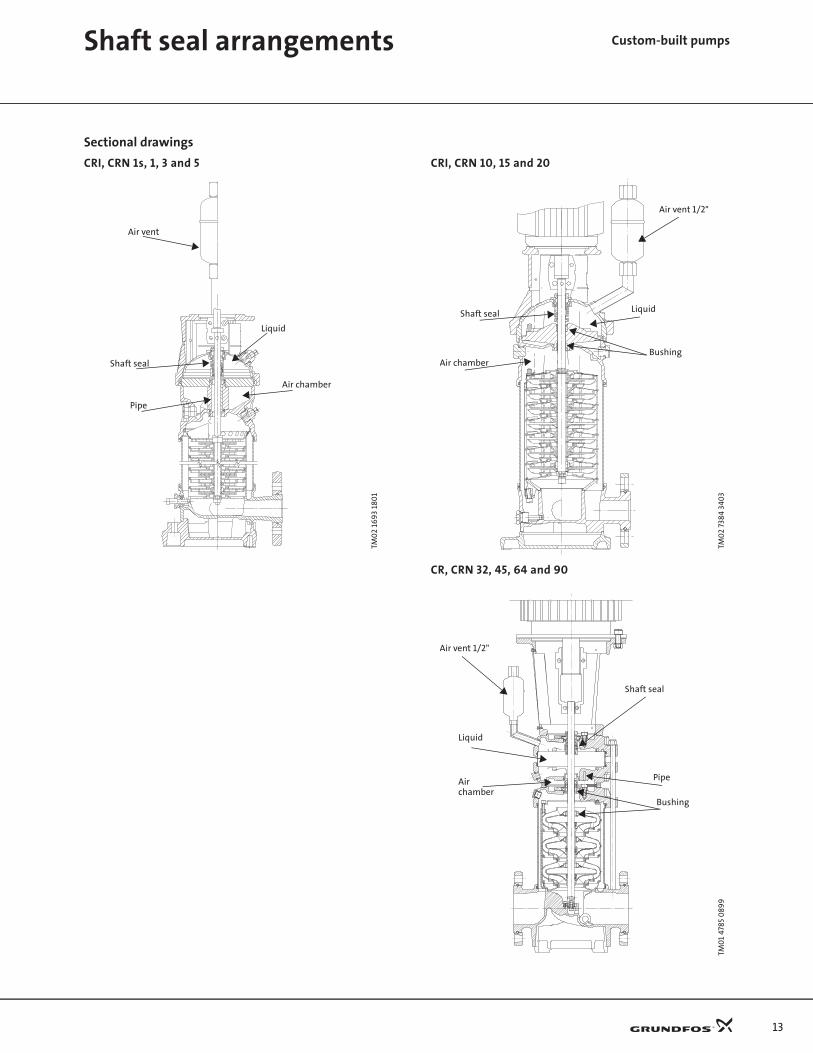
The air-cooled top separates the seal chamber from thepump by an air-cooled chamber, generating an insu-lating effect similar to that of a thermos.
Via the narrow passage between the pump and the air-cooled top, a small quantity of the pumped liquid recir-culates by natural circulation.
Temperatures above 248°F normally result in a substan-tial reduction of seal life due to poor lubrication of theseal faces. As the temperature in the seal chamber doesnot exceed 248°F during operation, a standard Grundfosshaft seal can be used.
The Grundfos air-cooled top does not require anyexternal cooling. An automatic air vent is required tovent the pump seal chamber.
Air-cooled top with bearing flange
For applications involving pumping of water up to 356°F,the pump requires a net positive inlet pressure,according to the vapor pressure of water.
To prevent the axial thrust generated by the inlet pres-sure from being transmitted to the motor shaft andbearings, a bearing flange can be fitted between pumpand motor.
A bearing flange may be required if the application inletpressure exceeds the maximum inlet pressure of thepump. This is common for pumps with 1 or 2 impellers.Refer to the CR, CRI, CRN Product Guide for maximumpermissible inlet pressures for all CR pumps.
The max. permissible operating pressure of pumps withair-cooled top for temperatures up to 356°F is 362 psi.
Dimensions
Reference numbers, air-cooled top for 248-356°F
GR5
228
Pump type
CR 1s CR 1 CR 3 CR 5 CR 10 CR 15 CR 20 CR 32 CR 45 CR 64 CR 90
CR
CRI
CRN
Pump typeAdditional pump height *
[in]
CRI, CRN 1s, 1, 3 and 5 4 1/4
CRI, CRN 10, 15 and 20 3 1/2
CR, CRN 32 8 1/4
CR, CRN 45 9 1/2
CR, CRN 64 6 1/2
CR, CRN 90 7 1/4
*This dimension is the additional height as compared to the standard pump.
Pump type Reference number
CRI, CRN 1s, 1, 3 and 5 98 96 40
CRI, CRN, 10, 15 and 20 98 94 73
CR 32, 45, 64 and 90 98 96 38
CRN 32 and 45 98 96 37
CRN 64 and 90 98 96 36
13
Sectional drawings
CRI, CRN 1s, 1, 3 and 5 CRI, CRN 10, 15 and 20
CR, CRN 32, 45, 64 and 90
TM0
2 16
93
180
1
Air vent
Shaft seal
Liquid
Air chamber
Pipe
TM0
2 73
84 3
403
TM0
1 47
85 0
899
Air vent 1/2"
Shaft seal Liquid
Air chamberBushing
••
• •
•
•
•
•
•
Air vent 1/2"
Shaft seal
Liquid
Air
Bushingchamber
Pipe
Shaft seal arrangements Custom-built pumps
14
Custom-built pumpsShaft seals
Shaft seals
General information
Liquids or applications exceeding the range of normaloperating conditions require special-purpose shaft sealsolutions.
To ensure reliability and avoid untimely breakdowns,the following conditions must be considered:
• temperature,
• pressure,
• pumped liquid.
In order to meet any specific requirements, Grundfosoffers the following variants:
1. Shaft seals with FFKM or FXM O-ring material
2. Hybrid shaft seals
Recommended operating range
The actual operating range of the shaft seal depends onthe operating pressure, pump type, type of shaft sealand liquid temperature. The following table applies toclean water and water containing glycol.
For explanation of codes, see the type key on page 5.
For pumps equipped with a Cool-Top the maximumoperation temperature is 356°F.
Shaft seal with FFKM or FXM O-ring material
General information
Shaft seals with FFKM or FXM O-ring material are recom-mended for applications where the pumped liquids maydamage the standard O-ring material.
See the list of pumped liquids in the CR, CRI, CRN databooklet.
Reference applications, FFKM (Kalrez®)
• Chemical industry (aggressive liquids)
• Petrochemical industry (oils)
• High-temperature applications.
Plug and sleeve O-rings made of FFKM are also availablefor CR, CRI, CRN 1s, 1, 3, 5, 10, 15 and 20.
Reference applications, FXM (Flouraz®)
• High-temperature applications (instead of FKM).
Plug and sleeve O-rings made of FXM are available forthe full range.
Pump range
Shaft seals with FFKM or FXM O-ring are available for thefollowing Grundfos pumps:
Technical description
The FFKM and FXM O-rings replace the standard shaftseal O-rings.
Dimensions
Dimensions are identical to those of the standard shaftseal.
Reference numbers
Pump type Shaft sealMin.
temp.[°F]
Max.temp.
[°F]
Pressurerating[psi]
CR, CRI, CRN1s, 1, 3, 5, 10, 15, 20, 32, 45, 64, and 90
HUBx 32 248 435
HUUx –40 194 435
HQQx –40 248 435
HQBx 0 248 435
Rubber type Min. temperature [°F] Max. temperature [°F]
EPDM –40 248
FKM –4 194
FXM 14 527
FFKM –4 527
Maximum operation temperature is 248°F for the standard range.
Pump type
CR 1s CR 1 CR 3 CR 5 CR 10 CR 15 CR 20 CR 32 CR 45 CR 64 CR 90
FFKM
FXM
Pump typeReference number
FFKM FXM
CR, CRI, CRN 1s, 1, 3 and 5 98 99 72 98 96 78
CR, CRI, CRN 10, 15 and 20 98 94 74 98 94 75
CR, CRN 32, 45, 64 and 90 98 98 15 98 96 77

15
Shaft seals Custom-built pumps
Hybrid shaft seal
General information
Hybrid shaft seals are recommended for applicationsinvolving a risk of dry running and are available as astandard shaft seal on CR, CRN 32, 45, 64 and 90; sealtype KUHE.
Reference applications
• Boiler-feed applications
• Applications involving degassing of liquids
• Industrial applications involving frequent priming.
Pump range
Hybrid shaft seals are available for the followingGrundfos pumps:
Technical description
The stationary seat of the shaft seal is equipped with anextra, special-carbon seal face, expanding at hightemperatures as a result of dry running or similar condi-tions.
This eliminates the usual damaging effects of dryrunning, such as leakage and noise.
Sectional drawing
Dimensions
Dimensions are identical to those of the standard shaftseal.
Reference numbers
Pump type
CR 1s CR 1 CR 3 CR 5 CR 10 CR 15 CR 20 CR 32 CR 45 CR 64 CR 90
CR
CRI
CRN
TM0
2 42
79 0
402
Pump type Reference number
CR, CRN 32, 45, 64 and 90 Standard
Hybrid seal design

16
Custom-built pumpsCertificates
Certificates
General information
Grundfos offer a number of certificates for differentpurposes. The following types are available...
• material certificates( certificates stating material components or material specifications)
• performance certificates(printed test reports guaranteeing and certifying test data of QH performance, current consumption curves, rpm, etc.)
• authorized test by third party(surveyed performance test)
• ATEX approved CR pumps(according to ATEX-directive 94/9/EC)
The certificates must be ordered with the pump.
Reference applications
• Pharmaceutical industries
• Ships and offshore
• Big contractors
• Areas exposed to explosive atmosphere
Pump range
Certificates are available for the following pump types:
GR
5381
Pump type
CR 1s CR 1 CR 3 CR 5 CR 10 CR 15 CR 20 CR 32 CR 45 CR 64 CR 90
CR
CRI
CRN
Certificate Standard
Material specification report
Material report with certificate
ReportATEX-approved pump
Inspection certificate EN 10.204 3.1.B
Inspection certificate- Lloyds Register of Shipping (LRS), - Det Norske Veritas (DNV)- Germanisher Lloyd (GL)- Bureau Veritas (BV)- Etc.....
EN 10.204 3.1.C
Surface roughness report
Motor test report
Standard test report ISO 9906
Vibration report
Certificate of compliance with the order
EN 10.204 2.1
Test report - non specific inspection and testing
EN 10.204 2.2
ReportCleaned and dried pump
ReportElectro-polished pump
Part no 96 51 22 40/A53123
ATEX-approved pump
Grundfos hereby confirms that the pump mentioned above is manufactured according the specifications mentioned in the “CR, CRI, CRN Custom-built pumps” data booklet. This means the pump is conformity with the ATEX 94/9EEC (ATEX 100) appendix VIII directive as men-tioned in the “ATEX Supplement to installation and operating instructions” supplied with the pump.
GRUNDFOS Date:
Signature:
Name: Dept.:
Customer name Customer order no. Grundfos order no. Pump type Part number Production code Pump serial no. Motor serial no. ATEX approval of pump
Part no 96 50 79 31/A53123
Surface roughness According to ISO 1302
Customer name Customer order no. Grundfos order no. Pump type Part number CRN base part number
The surface roughness is measured as the maximum roughness of the CRN inlet and outlet surface.
B A
Surface Treatment None
Roughnessvalue RA [µm]
Roughnessdegree
Electro-polished 50 N 12 25 N 11 12.5 N 10 Measured values A 6.3 N 9 R max [µm] 3.2 N 8 R A [µm] 1.6 N 7 R Z [µm] 0.8 N 6 0.4 N 5 Measured values A 0.2 N 4 R max [µm] 0.1 N 3 R A [µm] 0.05 N 2 R Z [µm] 0.025 N 1
GRUNDFOSDate:
Signature:
Name:
Dept.:
Part no 96 50 79 32/A53123
Vibration reportAccording to ISO 10816
Measured object Pump type Part number P2 (kW) Frequency (Hz) Number of poles Serial no.
Test conditions Voltage (V) Frequency: (Hz) Flow (m³/h) Head (m)
The pump is floor-mounted on vibration absorbers. For vibration velocity measurement positions, see figure.
Remarks
Result of measurement:
Pos RMS vibration velocity (mm/s)
12 3 4 5 6 7 8 9
Typical zone boundry limits
RMS vibration velocity (mm/s)
Class I Class II
0.28
0.45
0.71
A
1.12
A
1.8B
2.8B
4.5C
7.1C
11.2
18
28
45
DD
The machine classifications are as follows: Class I: Individual parts of engines and machines, integrally connected to the complete machine in its normal operating condition. (Production electrical motors of up to 15 kW are typical examples of machines in this category.)
Class II: Medium-sized machines (typically electrical motors with 15 kW to 75 kW output) without special foundations, rigidly mounted engines or machines (up to 300 kW) on spe-cial foundations.
GRUNDFOSDate: 25-Jun-04
Signature:
Name:
Dept.:

17
Certificates Custom-built pumps
ATEX-approved CR pumps
General information
The CR pumps can be approved according to EC directive94/9/EC, the so-called ATEX directive.
The pumps can be used in areas (zones) classifiedaccording to the directive 1999/92/EC. In case of doubt,please consult the above-mentioned directives orcontact Grundfos.
ATEX-approved pumps will be supplied with serialnumber, special installation and operating instructionsand a nameplate including the ATEX classification.
An ATEX-approved pump report is available on request.
Scope of ATEX categories for CR pumps
1) Solutions including MAGdrive or double shaft seal.
2) Note: To enable the use of category 3 G CR pumps in zone 1 areas, the minimum requirement is a dry-running protection approved for zone 1. The dry-running protection must stop the pumps if the liquid supply ceases.
Group I
Category M2
Underground installations in mines lia-ble to be endangered by explosive gas-ses or combustible dust.
Pumps made of materials that do not create sparks and thus do not constitute any danger of explosion.
CR pumps available CR, CRI, CRN
Motors available None*
* Air or hydraulic motors are not available from Grundfos.
Group II
Category 2 Category 3
Installation areas liable to be endan-gered by explosive atmospheres.
Pumps intended for use in areas in which explosive atmospheres are likely to occur.
Pumps intended for use in areas in whichexplosive atmospheres only rarely occur.
G (gas) D (dust) G (gas) 2) D (dust)
CR pumps available CR, CRI, CRN 1) CR, CRI, CRN, CRT CR, CRI, CRN, CRT CR, CRI, CRN, CRT
Motors availableVEM 2G EEx e IIT3CEMP 2G EEc d IIB T4
VEM 2D 125°CVEM 2G EEx e IIT3CEMP 2G EEc d IIB T4
VEM 3D 125°C
18
Custom-built pumpsMAGdrive
Magnetic-drive pump (MAGdrive)
General information
The zero-leakage, custom-built pump with magneticdrive (MAGdrive) is recommended for the pumping ofhazardous or aggressive liquids. Grundfos MAGdriveprotects the surrounding environment and the peopleworking in the vicinity of the pump.
Reference applications
• Chemical industry (aggressive or toxic liquids)
• Petrochemical industry (volatile liquids)
• Pharmaceutical industry.
Pump range
The following Grundfos pumps are available withMAGdrive:
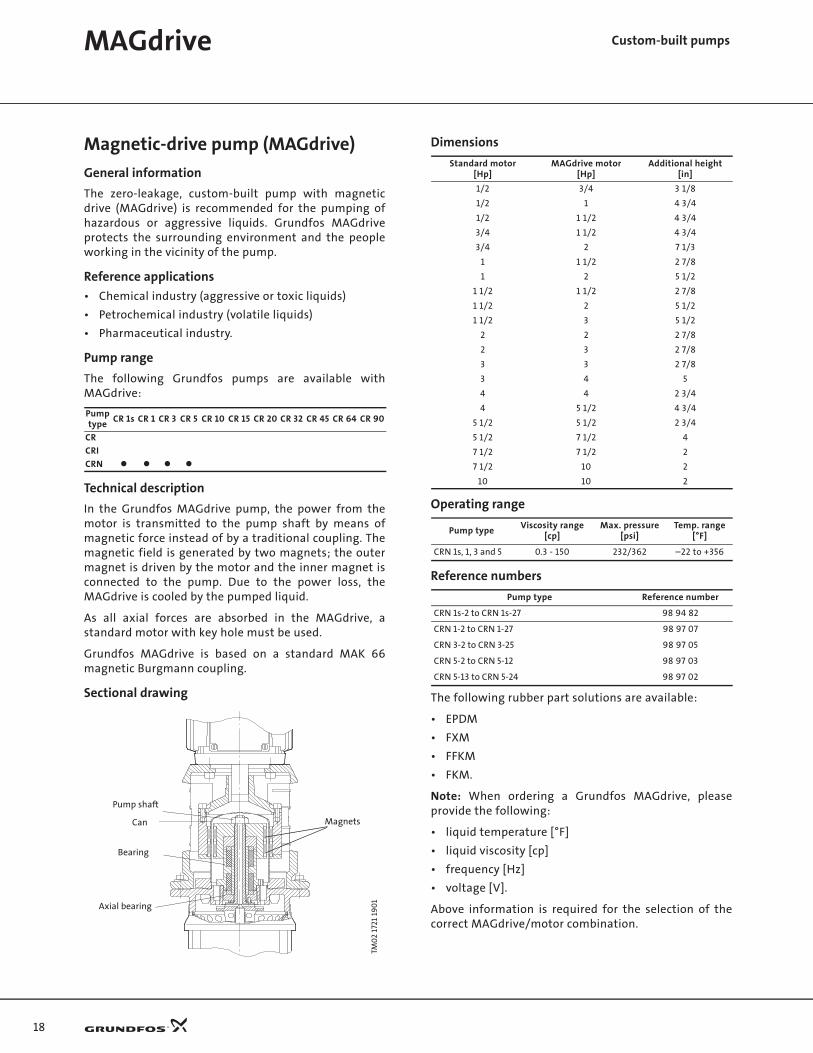
Technical description
In the Grundfos MAGdrive pump, the power from themotor is transmitted to the pump shaft by means ofmagnetic force instead of by a traditional coupling. Themagnetic field is generated by two magnets; the outermagnet is driven by the motor and the inner magnet isconnected to the pump. Due to the power loss, theMAGdrive is cooled by the pumped liquid.
As all axial forces are absorbed in the MAGdrive, astandard motor with key hole must be used.
Grundfos MAGdrive is based on a standard MAK 66magnetic Burgmann coupling.
Sectional drawing
Dimensions
Operating range
Reference numbers
The following rubber part solutions are available:
• EPDM
• FXM
• FFKM
• FKM.
Note: When ordering a Grundfos MAGdrive, pleaseprovide the following:
• liquid temperature [°F]
• liquid viscosity [cp]
• frequency [Hz]
• voltage [V].
Above information is required for the selection of thecorrect MAGdrive/motor combination.
Pumptype
CR 1s CR 1 CR 3 CR 5 CR 10 CR 15 CR 20 CR 32 CR 45 CR 64 CR 90
CR
CRI
CRN
TM0
2 17
21 1
90
1
265
250
258
259
Magnets
Axial bearing
Bearing
Can
Pump shaft
Standard motor[Hp]
MAGdrive motor[Hp]
Additional height[in]
1/2 3/4 3 1/8
1/2 1 4 3/4
1/2 1 1/2 4 3/4
3/4 1 1/2 4 3/4
3/4 2 7 1/3
1 1 1/2 2 7/8
1 2 5 1/2
1 1/2 1 1/2 2 7/8
1 1/2 2 5 1/2
1 1/2 3 5 1/2
2 2 2 7/8
2 3 2 7/8
3 3 2 7/8
3 4 5
4 4 2 3/4
4 5 1/2 4 3/4
5 1/2 5 1/2 2 3/4
5 1/2 7 1/2 4
7 1/2 7 1/2 2
7 1/2 10 2
10 10 2
Pump typeViscosity range
[cp]Max. pressure
[psi]Temp. range
[°F]
CRN 1s, 1, 3 and 5 0.3 - 150 232/362 –22 to +356
Pump type Reference number
CRN 1s-2 to CRN 1s-27 98 94 82
CRN 1-2 to CRN 1-27 98 97 07
CRN 3-2 to CRN 3-25 98 97 05
CRN 5-2 to CRN 5-12 98 97 03
CRN 5-13 to CRN 5-24 98 97 02
19
Custom-built pumpsLiqTec
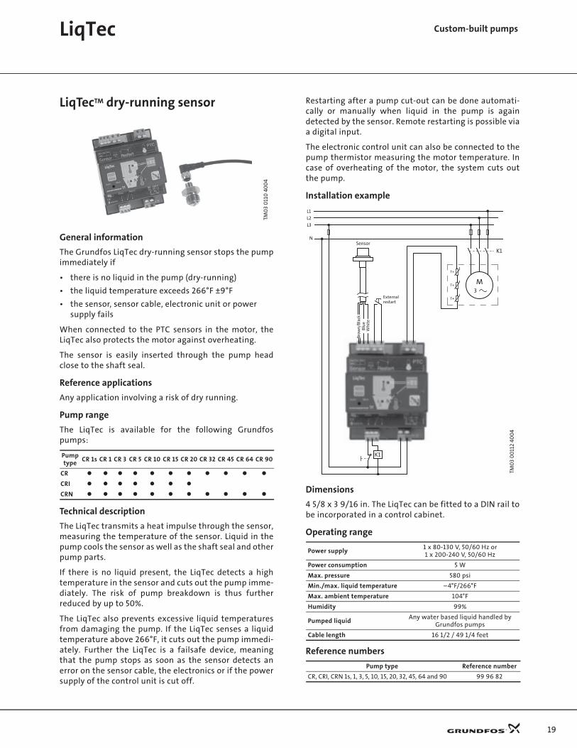
LiqTecTM dry-running sensor
General information
The Grundfos LiqTec dry-running sensor stops the pumpimmediately if
• there is no liquid in the pump (dry-running)
• the liquid temperature exceeds 266°F ±9°F
• the sensor, sensor cable, electronic unit or power supply fails
When connected to the PTC sensors in the motor, theLiqTec also protects the motor against overheating.
The sensor is easily inserted through the pump headclose to the shaft seal.
Reference applications
Any application involving a risk of dry running.
Pump range
The LiqTec is available for the following Grundfospumps:
Technical description
The LiqTec transmits a heat impulse through the sensor,measuring the temperature of the sensor. Liquid in thepump cools the sensor as well as the shaft seal and otherpump parts.
If there is no liquid present, the LiqTec detects a hightemperature in the sensor and cuts out the pump imme-diately. The risk of pump breakdown is thus furtherreduced by up to 50%.
The LiqTec also prevents excessive liquid temperaturesfrom damaging the pump. If the LiqTec senses a liquidtemperature above 266°F, it cuts out the pump immedi-ately. Further the LiqTec is a failsafe device, meaningthat the pump stops as soon as the sensor detects anerror on the sensor cable, the electronics or if the powersupply of the control unit is cut off.
Restarting after a pump cut-out can be done automati-cally or manually when liquid in the pump is againdetected by the sensor. Remote restarting is possible viaa digital input.
The electronic control unit can also be connected to thepump thermistor measuring the motor temperature. Incase of overheating of the motor, the system cuts outthe pump.
Installation example
Dimensions
4 5/8 x 3 9/16 in. The LiqTec can be fitted to a DIN rail tobe incorporated in a control cabinet.
Operating range
Reference numbers
TM0
3 0
110
40
04
Pump type
CR 1s CR 1 CR 3 CR 5 CR 10 CR 15 CR 20 CR 32 CR 45 CR 64 CR 90
CR
CRI
CRN
TM0
3 0
011
2 40
04
Power supply1 x 80-130 V, 50/60 Hz or1 x 200-240 V, 50/60 Hz
Power consumption 5 W
Max. pressure 580 psi
Min./max. liquid temperature –4°F/266°F
Max. ambient temperature 104°F
Humidity 99%
Pumped liquidAny water based liquid handled by
Grundfos pumps
Cable length 16 1/2 / 49 1/4 feet
Pump type Reference number
CR, CRI, CRN 1s, 1, 3, 5, 10, 15, 20, 32, 45, 64 and 90 99 96 82
Sensor
3
M
K1
T+
T+
T+
K1
N
L3
L2
L1
Brow
n/Bl
ack
Blu
eW
hit
e
Externalrestart

20
Custom-built pumpsPumps
Horizontally mounted pumps
General information
For safety and space-saving reasons, the pump can bemounted in the horizontal position.
Reference applications
• Ships
• Earthquake areas (low center of gravity)
• Places with limited access and space.
Pump range
The following Grundfos pumps are available for hori-zontal mounting:
Also available for CRT 2, 4, 8, 16.
Technical description
The pumps are supplied with separate mounting platesfor support of pump and motor.
Note: The following pump types are fitted with a B3 / B5foot/flange mounted motor:
• CR, CRI, CRN 1 to 20 with motors ≥ 10 Hp and
• CR, CRN 32, 45, 64 and 90.
Reference numbers
Dimensional drawings
CR, CRI, CRN 1s, 1, 3, 5, CR, CRI, CRN 10, 15 and 20 <= 5 Hp
CR, CRI, CRN 10, 15 and 20 >=7.5 Hp
CR, CRN 32, 45, 64 and 90
GR
5379
Pump type
CR 1s CR 1 CR 3 CR 5 CR 10 CR 15 CR 20 CR 32 CR 45 CR 64 CR 90
CR
CRI
CRN
Pump type Reference number
CR, CRI, CRN 1s, 1, 3 and 5 98 99 51
CR, CRI, CRN 10, 15 and 20 <= 5 Hp 98 94 76
CR, CRI, CRN 10, 15 and 20 >= 7.5 Hp 98 94 77
CR, CRN 32, 45, 64 and 90 98 98 53
TM0
2 83
72 5
00
3TM
02
8373
50
03
TM0
2 74
26 3
403
L
H
CX
B
B
B1
L
H
X
B
B1
AAAAAA
BB B
4 x ø14
AB
D
8
L
H
X
AAAAAA
BB B
4 x ø19
AB
D
8
256
21
Pumps Custom-built pumps
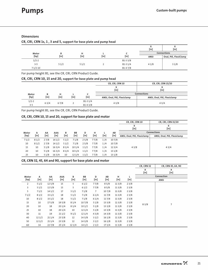
Dimensions
CR, CRI, CRN 1s, 1 , 3 and 5, support for base plate and pump head
For pump height B1, see the CR, CRI, CRN Product Guide.
CR, CRI, CRN 10, 15 and 20, support for base plate and pump head
For pump height B1, see the CR, CRI, CRN Product Guide.
CR, CRI, CRN 10, 15 and 20, support for base plate and motor
CR, CRN 32, 45, 64 and 90, support for base plate and motor
X[in]
X[in]
Motor[hp]
B[in]
H[in]
L[in]
C[in]
Connections
ANSI Oval, PJE, FlexiClamp
1/2-2
5 1/2 5 1/2 2
B1-3 3/8
4 1/8 3 1/83-5 B1-3 1/4
7 1/2-10 B1-4 7/8
CR, CRI, CRN 10 CR, CRI, CRN 15/20
X[in]
X[in]
Motor[hp]
B[in]
H[in]
L[in]
C[in]
Connections
ANSI, Oval, PJE, Flexiclamp ANSI, Oval, PJE, Flexiclamp
1/2-26 3/4 6 7/8 2
B1-3 1/44 3/8 4 3/4
3-5 B1-4 3/8
CR, CRI, CRN 10 CR, CRI, CRN 15/20
X[in]
X[in]
Motor[hp]
A[in]
AA[in]
AAA[in]
B[in]
BB[in]
D[in]
H[in]
L[in]
AB[in]
Connections
ANSI, Oval, PJE, Flexiclamp ANSI, Oval, PJE, Flexiclamp
7 1/2 8 1/2 2 7/8 14 1/2 5 1/2 7 1/8 2 5/8 7 7/8 1 /4 10 7/8
4 3/8 4 3/4
10 8 1/2 2 7/8 14 1/2 5 1/2 7 1/8 2 5/8 7 7/8 1 /4 10 7/8
15 10 5 1/8 16 3/4 8 1/4 10 1/4 1 1/2 7 7/8 1 /4 12 3/4
20 10 5 1/8 16 3/4 8 1/4 10 1/4 1 1/2 7 7/8 1 /4 13 1/8
25 10 5 1/8 16 3/4 10 12 1/4 1 1/2 7 7/8 1 /4 13 1/8
CR, CRN 32 CR, CRN 45, 64, 90
X[in]
X[in]
Motor[hp]
A[in]
AA[in]
AAA[in]
B[in]
BB[in]
D[in]
AB[in]
H[in]
L[in]
Connection
ANSI
2 5 1/2 12 5/8 15 5 6 1/2 7 7/8 8 5/8 11 3/8 2 3/8
8 3/8 7
3 5 1/2 12 5/8 15 5 6 1/2 7 7/8 8 5/8 11 3/8 2 3/8
5 7 1/2 14 1/2 17 5 1/2 7 1/8 7 10 7/8 11 3/8 2 3/8
7 1/2 8 1/2 15 1/2 18 5 1/2 7 1/8 6 1/4 11 7/8 11 3/8 2 3/8
10 8 1/2 15 1/2 18 5 1/2 7 1/8 6 1/4 11 7/8 11 3/8 2 3/8
15 10 17 3/8 19 5/8 8 1/4 10 7/8 5 1/8 13 3/8 11 3/8 2 3/8
20 10 18 20 1/4 8 1/4 10 1/2 5 1/8 13 3/8 11 3/8 2 3/8
25 10 18 20 1/4 10 12 1/4 5 1/8 13 3/8 11 3/8 2 3/8
30 11 19 21 1/2 9 1/2 12 1/4 4 3/8 14 3/8 11 3/8 2 3/8
40 12 1/2 21 1/4 23 5/8 12 14 3/8 3 1/2 16 1/8 11 3/8 2 3/8
50 12 1/2 21 1/4 23 5/8 12 14 3/8 3 1/2 16 1/8 11 3/8 2 3/8
60 14 22 7/8 25 1/4 12 1/4 14 1/2 2 1/2 17 3/4 11 3/8 2 3/8
22
Pumps Custom-built pumps
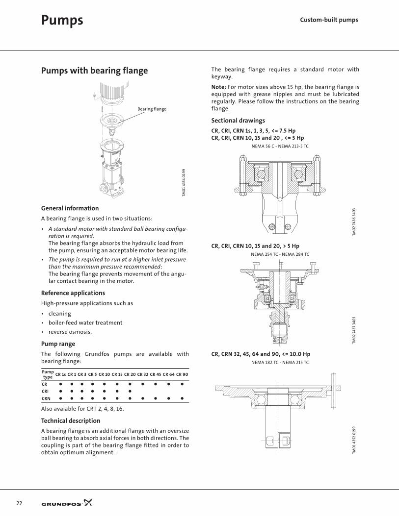
Pumps with bearing flange
General information
A bearing flange is used in two situations:
• A standard motor with standard ball bearing configu-ration is required: The bearing flange absorbs the hydraulic load from the pump, ensuring an acceptable motor bearing life.
• The pump is required to run at a higher inlet pressure than the maximum pressure recommended:The bearing flange prevents movement of the angu-lar contact bearing in the motor.
Reference applications
High-pressure applications such as
• cleaning
• boiler-feed water treatment
• reverse osmosis.
Pump range
The following Grundfos pumps are available withbearing flange:
Also avaiable for CRT 2, 4, 8, 16.
Technical description
A bearing flange is an additional flange with an oversizeball bearing to absorb axial forces in both directions. Thecoupling is part of the bearing flange fitted in order toobtain optimum alignment.
The bearing flange requires a standard motor withkeyway.
Note: For motor sizes above 15 hp, the bearing flange isequipped with grease nipples and must be lubricatedregularly. Please follow the instructions on the bearingflange.
Sectional drawings
CR, CRI, CRN 1s, 1, 3, 5, <= 7.5 HpCR, CRI, CRN 10, 15 and 20 , <= 5 Hp
CR, CRI, CRN 10, 15 and 20, > 5 Hp
CR, CRN 32, 45, 64 and 90, <= 10.0 Hp
TM0
1 43
54 0
199
Pumptype
CR 1s CR 1 CR 3 CR 5 CR 10 CR 15 CR 20 CR 32 CR 45 CR 64 CR 90
CR
CRI
CRN
Bearing flange
NEMA 56 C - NEMA 213-5 TC
TM0
2 74
36 3
403
NEMA 254 TC - NEMA 284 TC
TM0
2 74
37 3
403
NEMA 182 TC - NEMA 215 TC
TM0
1 43
52 0
199

23
CR, CRN 32, 45, 64 and 90, >10 Hp
Dimensions
The following additional height must be added to thetotal height of the pump:
CR, CRI, CRN 1s, 1, 3, 5, 10, 15 and 20
CR, CRN 32, 45, 64 and 90
Reference numbers
CR, CRI, CRN 1s, 1, 3, 5, <= 7.5 HpCR, CRI, CRN 10, 15 and 20, <= 5 Hp
CR, CRI, CRN 10, 15 and 20,> 5 Hp
CR, CRN 32, 45, 64 and 90
NEMA 254 TSC - NEMA 365 TSC
TM0
1 43
53 0
503
Motor type Motor powerAdditional
height[in]
NEMA 56C/148.2 1/3 - 2 [Hp] 1 1/2
NEMA F182 TC 3 - 5 [Hp] 1 3/4
NEMA 213-5 TC 7 1/2 [Hp] 1 3/4
NEMA 254-6 15 [Hp] 3 7/8
NEMA 284-6 20-40 [Hp] 5 1/3
Motor type Motor powerAdditional
height[in]
NEMA 182 TC - NEMA 215 TC 3 - 10 [Hp] 7/8
NEMA 254 TSC - NEMA 365 TSC 15 - 60 [Hp] 5/8
Motor type Motor powerBearing type
in flangeReference
number
NEMA 56C/148.2 1/3 - 2 [Hp] 6308 2RS C3 98 96 51
NEMA F182 TC 3 - 5 [Hp] 6310 2RS C3 98 96 50
NEMA 213-5 TC 7 1/2 [Hp] 6310 2RS C3 98 96 49
Motor type Motor powerBearing type
in flangeReference
number
NEMA 254-6 15 [Hp] QJ 216 MPA 98 94 87
NEMA 284-6 20-40 [Hp] QJ 216 MPA 98 94 88
Motor type Motor powerBearing type
in flangeReference
number
NEMA 182 TC 3-5 [Hp] 6310 2RS 98 98 45
NEMA 213 TCNEMA 215 TC
7 1/2-10 [Hp] 6310 2RS 98 98 14
NEMA 254 TSCNEMA 256 TSC
15 [Hp] QJ 216 MPA 98 98 42
NEMA 284 TSCNEMA 286 TSC
20-40 [Hp] QJ 216 MPA 98 98 41
NEMA 324 TSCNEMA 326 TSCNEMA 364 TSCNEMA 365 TSC
50-60 [Hp] QJ 216 MPA 98 98 40
Pumps Custom-built pumps

24
Pumps Custom-built pumps
Belt-driven pumps
General information
A belt-driven pump is designed to operate in places withlimited space or where no electrical power is available.
Reference applications
Diesel-engine-driven or steam-turbine-driven applica-tions such as:
• applications in remote/distant areas
• mobile applications
• fire protection.
Pump range
The following Grundfos pumps are available as belt-driven pumps:
Also available for CRT 2, 4, 8, 16.
Technical description
An additional bearing has been added on top of anexisting bearing flange. The two bearings are mountedback-to-back. This bearing design makes it possible towithstand the extra radial forces caused by a pulley.
A pulley wheel is attached to the end of the shaft.
By means of pulley belts, the pump can be driven by amotor mounted next to it rather than on top of it.
The pump can be mounted horizontally or vertically byusing the extra support plates.
The pulley head is positioned on the motor stool wherethe motor would normally be fitted. Using the existingholes in the motor stool, the pulley head can be securedto the motor stool with bolts, washers and nuts. Thepulley wheel is then attached to the shaft using anappropriate bush and key.
For extended bearing life, the following pulley wheelsizes are recommended:
GR5
886
Pumptype
CR 1s CR 1 CR 3 CR 5 CR 10 CR 15 CR 20 CR 32 CR 45 CR 64 CR 90
CR
CRI
CRN
Pulley headType III
1/2 - 7 1/2 Hp
Type IV
10 - 25 Hp
Type II
2 - 10 Hp
Type I
15 - 60 Hp
Pump typeCR, CRI, CRN
1s, 1, 3, 5,10, 15, 20
CR, CRI, CRN10, 15, 20
CR, CRN 32, 45, 64, 90
Pulley wheel diameter
ø4 3/8- 5 3/8 Min. ø7 7/8 Min. ø6 1/4Min.
ø7 7/8
Number of belts 2 Min. 3 Min. 2 Min. 3
Pump speed [rpm]
Max 3000

25
Sectional drawings
CR, CRI, CRN 1s, 1, 3, 5, 10, 15 and 20 (type III)
CR, CRI, CRN 10, 15 and 20 (type IV)
CR, CRN 32, 45, 64 and 90 (type II)
CR, CRN 32, 45, 64 and 90 (type I)
Dimensions
Reference numbers
For horizontal installation, the belt-driven pumps aresupplied with both brackets as standard.
TM0
2 47
83 1
60
2TM
02
7451
350
3TM
02
4785
16
02
TM0
2 47
84
160
2
Pump type Pulley headAdditional height
from top of motor stool[in]
CR, CRI, CRN 1s, 1, 3, 5, 10, 15, 20 Type III 5 3/4
CR, CRI, CRN 10, 15, 20 Type IV 12 1/4
CR, CRN 32, 45, 64 and 90Type II 4 7/8
Type I 5 7/8
Pump type Pulley head Reference number
CR, CRI, CRN 1s, 1, 3, 5, 10, 15, 20 Small 98 96 48
CR, CRI, CRN 10, 15, 20 Type II 98 94 89
CR, CRN 32, 45, 64 and 90Type II 98 96 47
Type I 98 96 46
Pumps Custom-built pumps

26
Pumps Custom-built pumps
Pumps for liquid temperatures down to –40°F
General information
Grundfos offers pumps suitable for the pumping ofliquids of extreme temperatures down to –40°F.
Reference applications
• Cooling systems with antifreeze and brines
• Ventilation systems
• Industrial processes.
Pump range
The following Grundfos pumps are available for liquidtemperatures down to –40°F:
Technical description
CRI, CRN 1s, 1, 3, 5, 10, 15 and 20 feature
• PTFE neck rings with inner diameter exceeding stand-ard dimensions.
Please note that pumped liquids containing antifreezeoften require the use of oversize motors due to thehigher viscosity of these liquids.
Dimensions
Dimensions are identical to those of a standard pump.
Reference numbers
GR
5219
Pump type
CR 1s CR 1 CR 3 CR 5 CR 10 CR 15 CR 20 CR 32 CR 45 CR 64 CR 90
CR
CRI
CRN
The standard CRN 32, 45, 64 and 90 pumps fitted with shaft seal type HQQE are capable of operating at liquid temperatures down to –40°F.
Pump type Reference number
CRI, CRN 1s, 1, 3 and 5 98 98 75
CRI, CRN 10, 15 and 20 98 94 78
27
Carbon-free pumps
General information
Certain processes such as industrial processes in theelectronics industry require the use of pumps containingabsolutely no carbon fibers.
Reference applications
• Ultra-purification processes
• Flushing processes in the electronics industry.
Pump range
The following Grundfos pumps are available as carbon-free pumps:
Technical description
A carbon-free pump differs from a standard pump in thefollowing ways:
• Bearings are made of SiC/SiC.
• Neck rings and bushes are made of carbon-free PTFE (white PTFE).
Dimensions
Dimensions are identical to those of a standard pump.
Reference numbers
Silicon-free pumps
General information
Silicon-free pumps are suitable for processes requiringthe use of pumps not containing silicon.
Reference applications
• Production of paint and varnish
• Cleaning processes in the electronics industry.
Pump range
The following Grundfos pumps are available as silicon-free pumps:
Technical description
A silicon-free pump differs from a standard pump in thefollowing ways:
• Only FKM rubber is used.
• All components, except the electric motor, are washed in "DX 380 Low-Voc cleaner".
• Spare parts ordered together with the pump are also washed in "DX 380 Low-Voc cleaner".
• The pump is assembled in a room separated from the production area.
• Tools used for the assembly of the pump do not contain silicon.
• The assembled pump is checked visually; performance is not tested.
• The pump is wrapped in silicon-free plastic before being packing.
Dimensions
Dimensions are identical to those of the standard pump.
Reference numbers
Pumptype
CR 1s CR 1 CR 3 CR 5 CR 10 CR 15 CR 20 CR 32 CR 45 CR 64 CR 90
CR
CRI
CRN
CR, CRI, CRN 1s, 1, 3, 5, 10, 15 and 20 are carbon-free as standard if non-carbon seal face material is chosen.
Pump type Number of stages Reference number
CR, CRN 32, 45, 64 and 90
1 - 2 98 98 02
3 - 7 98 96 94
8 - 14 98 96 93
Pumptype
CR 1s CR 1 CR 3 CR 5 CR 10 CR 15 CR 20 CR 32 CR 45 CR 64 CR 90
CR
CRI
CRN
Pump type Reference number
CR, CRI, CRN 1s, 1, 3, 5, 10, 15 and 20CR, CRN 32, 45, 64 and 90
98 99 54
Pumps Custom-built pumps

28
Pumps Custom-built pumps
Pumps for pharmaceutical andbiotechnological applications
General information
The Grundfos CRN range is designed for applicationsrequiring the sterilization and CIP capability of pipes,valves and pumps. (CIP = Cleaning-In-Place).
In addition, some applications make special demands onthe system in terms of safety or process technology.
Certificates can be ordered on request for
• WRC
• FDA (rubber parts)
• different material certificates, see page 16.
Solutions
Grundfos offers the following solutions to meet thesespecial requirements:
• TriClamp connection
• Cleaned and dried pumps
• Electropolished pumps.
TriClampA base with TriClamp connection is of a hygienic designwith a sanitary coupling for use in the pharmaceuticaland food industry.
The gasket is made of PTFE or EPDM.
Pump range
The base with TriClamp connection is available for thefollowing Grundfos pumps:
Reference numbers
Base with TriClamp connection
Part numbers
Two gaskets and two couplings
Pump type
CR 1s CR 1 CR 3 CR 5 CR 10 CR 15 CR 20 CR 32 CR 45 CR 64 CR 90
CR
CRI
CRN
GR5
841_
base
Pump type Reference number
CRI, CRN 1s, 1, 3 and 5 98 96 92
CRI, CRN 10 , 15 and 20 98 94 79
GR5
841_
clam
p
Pump typePipework
connectionGasket parts
Part number
CRI, CRN 1s, 1, 3 and 5 1 1/2" EPDM 96 51 53 74
CRI, CRN 1s, 1, 3 and 5 1 1/2" PTFE 96 51 53 75
CRI, CRN 10 , 15 and 20 2" EPDM 96 51 53 76
CRI, CRN 10 , 15 and 20 2" PTFE 96 51 53 77

29
Cleaned and dried pumps
Pump range
The following Grundfos pumps are available as cleanedand dried pumps:
Also available for CRT 2, 4, 8, 16.
Technical description
Prior to assembly, the pump components are washed inpure, hot soap water, rinsed in de-ionized water, anddried.
Note: Cleaned and dried pumps are not performancetested in a test bed.
The pumps are wrapped in a plastic bag before beingpacked.
Reference numbers
Electropolished pumps
General information
To substantially reduce the risk of corrosion of thematerials and improve the cleanability.
Reference applications
The pharmaceutical-/food-/electronic industry.
Pump range
The following Grundfos pumps are available as elec-tropolished pumps:
Technical description
The pump incorporates a standard shaft seal which hasnot been polished.
Electro-polishing removes burrs as well as metallic andnon-metallic inclusions, providing an extremely smooth,clean and corrosion-resistant stainless steel surface.
First all components are pickled in a mixture of nitricacid and hydrofluoric acid. Subsequently, the compo-nents are electropolished in a mixture of sulphuric acidand phosphoric acid. Finally, the components are passi-vated in nitric acid.
The CRN 1s, 1, 3, 5, 10, 15 and 20 cast parts are all mechanically polished before being electropolished.
Dimensions
Dimensions are identical to those of the standard pump.
Reference numbers
Pumptype
CR 1s CR 1 CR 3 CR 5 CR 10 CR 15 CR 20 CR 32 CR 45 CR 64
CR
CRI
CRN
Pump type Reference number
CRI, CRN 1s, 1, 3, 5, 10, 15 and 20 98 98 70
CR, CRN 32, 45, 64, 90 98 96 41
Pumptype
CR 1s CR 1 CR 3 CR 5 CR 10 CR 15 CR20 CR 32 CR 45 CR 64 CR 90
CR
CRI
CRN
Pump typeStainless steel
cast partsStainless steel
plate parts
Surfaceroughness
[µ in]
CRN 1s, 1, 3, 5, 10, 15 and 20equal to or below 32
CRN 32, 45, 64, 90400-600
equal to or below 32
Pump type Reference number
CRN 1s, 1, 3, 5 98 97 60
CRN 10, 15, 20 98 94 80
CRN 32, 45, 64, 90 98 96 25
Pumps Custom-built pumps
30
Custom-built pumpsLow-NPSH pumps
Low-NPSH pumps
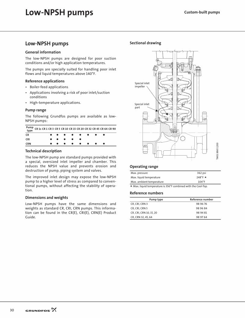
General information
The low-NPSH pumps are designed for poor suctionconditions and/or high application temperatures.
The pumps are specially suited for handling poor inletflows and liquid temperatures above 140°F.
Reference applications
• Boiler-feed applications
• Applications involving a risk of poor inlet/suction conditions
• High-temperature applications.
Pump range
The following Grundfos pumps are available as low-NPSH pumps:
Technical description
The low-NPSH pump are standard pumps provided witha special, oversized inlet impeller and chamber. Thisreduces the NPSH value and prevents erosion anddestruction of pump, piping system and valves.
The improved inlet design may expose the low-NPSHpump to a higher level of stress as compared to conven-tional pumps, without affecting the stability of opera-tion.
Dimensions and weights
Low-NPSH pumps have the same dimensions andweights as standard CR, CRI, CRN pumps. This informa-tion can be found in the CR(E), CRI(E), CRN(E) ProductGuide.
Sectional drawing
Operating range
Reference numbers
Pump type
CR 1s CR 1 CR 3 CR 5 CR 10 CR 15 CR 20 CR 32 CR 45 CR 64 CR 90
CR
CRI
CRN
TM0
1 88
65
120
0
Max. pressure 362 psi
Max. liquid temperature 248°F
Max. ambient temperature 104°F
Max. liquid temperature is 356°F combined with the Cool-Top.
Pump type Reference number
CR, CRI, CRN 3 98 96 76
CR, CRI, CRN 5 98 96 84
CR, CRI, CRN 10, 15, 20 98 94 81
CR, CRN 32, 45, 64 98 97 64
Special inletimpeller
Special inlet part
31
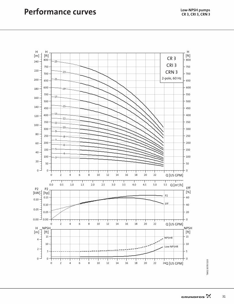
Low-NPSH pumpsCR 3, CRI 3, CRN 3Performance curves
TM0
2 83
78 5
103P
erfo
rman
ce c
urv
esC
R 3
0 2 4 6 8 10 12 14 16 18 20 22 Q [US GPM]
0
50
100
150
200
250
300
350
400
450
500
550
600
650
700
750
800
[ft]H
0.0 0.5 1.0 1.5 2.0 2.5 3.0 3.5 4.0 4.5 5.0 5.5 Q [m³/h]
0
20
40
60
80
100
120
140
160
180
200
220
240
[m]H
0
50
100
150
200
250
300
350
400
450
500
550
600
650
700
750
800
[ft]H
CR 3
2-pole, 60 Hz
CRI 3
CRN 3
-10
-11
-12
-13
-15
-17
-19
-21
-23
-25
-3
-4
-5
-6
-7-8
-9
0 2 4 6 8 10 12 14 16 18 20 22 Q [US GPM]
0.00
0.05
0.10
0.15
[hp]P2
0
20
40
60
Eff[%]
0.00
0.05
0.10
[kW]P2
P2
Eff
0 2 4 6 8 10 12 14 16 18 20 22 24Q [US GPM]
0
5
10
15
[ft]NPSH
0
5
10
15
[ft]NPSH
0
2
4
[m]H
Low NPSHR
NPSHR
32
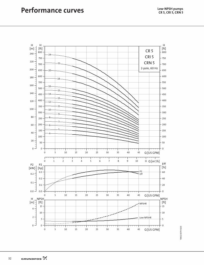
Performance curves Low-NPSH pumpsCR 5, CRI 5, CRN 5
TM0
2 83
79 5
103C
R 5
0 5 10 15 20 25 30 35 40 45 Q [US GPM]
0
50
100
150
200
250
300
350
400
450
500
550
600
650
700
750
800
[ft]H
0 1 2 3 4 5 6 7 8 9 10 11 Q [m³/h]
0
20
40
60
80
100
120
140
160
180
200
220
240
[m]H
0
50
100
150
200
250
300
350
400
450
500
550
600
650
700
750
800
[ft]H
CR 5
2-pole, 60 Hz
CRI 5
CRN 5
-10
-11
-12
-13
-14
-15
-16
-18
-20
-22
-24
-4
-5
-6
-7
-8
-9
0 5 10 15 20 25 30 35 40 45 Q [US GPM]
0.0
0.1
0.2
0.3
[hp]P2
0
20
40
60
Eff[%]
0.0
0.1
0.2
[kW]P2
P2Eff
0 5 10 15 20 25 30 35 40 45 Q [US GPM]
0
5
10
15
[ft]NPSH
0
5
10
15
[ft]NPSH
0
2
4
[m]H
Low NPSHR
NPSHR

33
Performance curves Low-NPSH pumpsCR 10, CRI 10, CRN 10
TM0
2 83
80 2
00
4 C
R 1
0
0 5 10 15 20 25 30 35 40 45 50 55 60 Q [US GPM]
0
50
100
150
200
250
300
350
400
450
500
550
600
650
700
750
800
[ft]H
0 1 2 3 4 5 6 7 8 9 10 11 12 13 14 15 Q [m³/h]
0
20
40
60
80
100
120
140
160
180
200
220
240
[m]H
0
50
100
150
200
250
300
350
400
450
500
550
600
650
700
750
800
[ft]H
CR 10
2-pole, 60 Hz
CRI 10
CRN 10
-17
-16
-14
-12
-10
-9
-8
-7
-6
-5
-4
-3
0 5 10 15 20 25 30 35 40 45 50 55 60 Q [US GPM]
0.0
0.2
0.4
0.6
0.8[hp]P2
0
20
40
60
80
Eff[%]
0.0
0.2
0.4
[kW]P2
P2Eff
0 5 10 15 20 25 30 35 40 45 50 55 60 Q [US GPM]
0
5
10
15
[ft]NPSH
0
5
10
15
[ft]NPSH
0
2
4
[m]H
Low NPSHR
NPSHR

34
Performance curves Low-NPSH pumpsCR 15, CRI 15, CRN 15
TM0
2 83
81 5
103C
R 1
5
0 10 20 30 40 50 60 70 80 90 100 110 Q [US GPM]
0
50
100
150
200
250
300
350
400
450
500
550
600
650
700
750
800
850[ft]H
0 2 4 6 8 10 12 14 16 18 20 22 24 26 28 Q [m³/h]
0
20
40
60
80
100
120
140
160
180
200
220
240
[m]H
0
50
100
150
200
250
300
350
400
450
500
550
600
650
700
750
800
850[ft]H
CR 15
2-pole, 60 Hz
CRI 15
CRN 15
-12
-10
-9
-8
-7
-6
-5
-4
-3
-2
0 10 20 30 40 50 60 70 80 90 100 110 Q [US GPM]
0.0
0.5
1.0
1.5
2.0[hp]P2
0
20
40
60
80
Eff[%]
0.0
0.5
1.0
[kW]P2
P2
Eff
0 10 20 30 40 50 60 70 80 90 100 110 Q [US GPM]
0
5
10
15
[ft]NPSH
0
5
10
15
[ft]NPSH
0
2
4
[m]H
Low NPSHR
NPSHR

35
Performance curves Low-NPSH pumpsCR 20, CRI 20, CRN 20
TM0
2 83
82 5
103C
R 2
0
0 10 20 30 40 50 60 70 80 90 100 110 120 130 140 Q [US GPM]
0
50
100
150
200
250
300
350
400
450
500
550
600
[ft]H
0 2 4 6 8 10 12 14 16 18 20 22 24 26 28 30 32 34 Q [m³/h]
0
20
40
60
80
100
120
140
160
180
[m]H
0
50
100
150
200
250
300
350
400
450
500
550
600
[ft]H
CR 20
2-pole, 60 Hz
CRI 20
CRN 20
-8
-7
-6
-5
-4
-3
-2
0 10 20 30 40 50 60 70 80 90 100 110 120 130 140 Q [US GPM]
0
1
2
3
4[hp]P2
0
20
40
60
80
Eff[%]
0
1
2
[kW]P2
P2
Eff
0 10 20 30 40 50 60 70 80 90 100 110 120 130 140 Q [US GPM]
0
10
20
30
[ft]NPSH
0
10
20
30
[ft]NPSH
0
4
8
[m]H
Low NPSHR
NPSHR
36
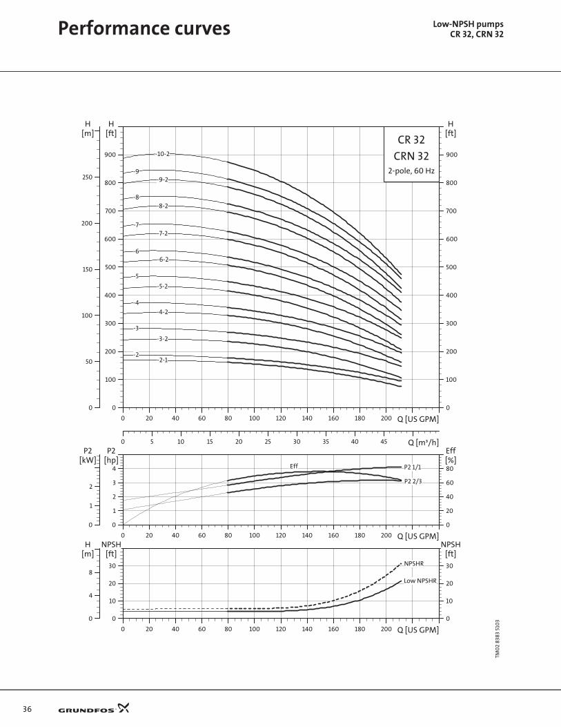
Performance curves Low-NPSH pumpsCR 32, CRN 32
TM0
2 83
83 5
103C
R 3
2
0 20 40 60 80 100 120 140 160 180 200 Q [US GPM]
0
100
200
300
400
500
600
700
800
900
[ft]H
0 5 10 15 20 25 30 35 40 45 Q [m³/h]
0
50
100
150
200
250
[m]H
0
100
200
300
400
500
600
700
800
900
[ft]H
CR 32
2-pole, 60 Hz
CRN 32-10-2
-2-2-1
-3
-3-2
-4
-4-2
-5
-5-2
-6-6-2
-7-7-2
-8-8-2
-9-9-2
0 20 40 60 80 100 120 140 160 180 200 Q [US GPM]
0
1
2
3
4[hp]P2
0
20
40
60
80[%]Eff
0
1
2
[kW]P2
P2 1/1
P2 2/3
Eff
0 20 40 60 80 100 120 140 160 180 200 Q [US GPM]
0
10
20
30
[ft]NPSH
0
10
20
30
[ft]NPSH
0
4
8
[m]H
Low NPSHR
NPSHR

37
Performance curves Low-NPSH pumpsCR 45, CRN 45
TM0
2 83
84 5
103C
R 4
5
0 20 40 60 80 100 120 140 160 180 200 220 240 260 280 Q [US GPM]
0
100
200
300
400
500
600
700
800
900
[ft]H
0 5 10 15 20 25 30 35 40 45 50 55 60 65 Q [m³/h]
0
50
100
150
200
250
[m]H
0
100
200
300
400
500
600
700
800
900
[ft]H
CR 45
2-pole, 60 Hz
CRN 45
-6-1
-7-2-7-1
-7
-2-2-1
-3-3-1
-3-2
-4-4-1
-4-2
-5-5-1
-5-2
-6
-6-2
0 20 40 60 80 100 120 140 160 180 200 220 240 260 280 Q [US GPM]
0
2
4
6
8[hp]P2
0
20
40
60
80[%]Eff
0
2
4
6[kW]
P2
P2 1/1
P2 2/3
Eff
0 20 40 60 80 100 120 140 160 180 200 220 240 260 280 Q [US GPM]
0
10
20
30
[ft]NPSH
0
10
20
30
[ft]NPSH
0
4
8
[m]H
Low NPSHR
NPSHR
38
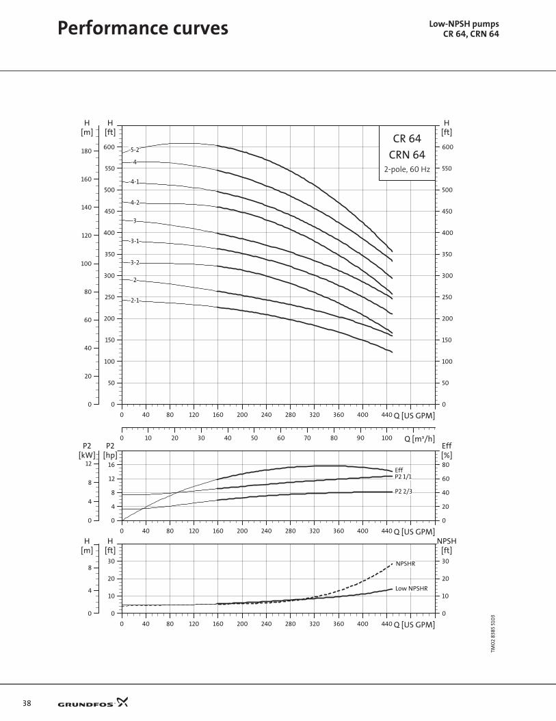
Performance curves Low-NPSH pumpsCR 64, CRN 64
TM0
2 83
85 5
103C
R 6
4
0 40 80 120 160 200 240 280 320 360 400 440 Q [US GPM]
0
50
100
150
200
250
300
350
400
450
500
550
600
[ft]H
0 10 20 30 40 50 60 70 80 90 100 Q [m³/h]
0
20
40
60
80
100
120
140
160
180
[m]H
0
50
100
150
200
250
300
350
400
450
500
550
600
[ft]H
CR 64
2-pole, 60 Hz
CRN 64-5-2
-4
-2
-2-1
-3
-3-1
-3-2
-4-1
-4-2
0 40 80 120 160 200 240 280 320 360 400 440 Q [US GPM]
0
4
8
12
16[hp]P2
0
20
40
60
80[%]Eff
0
4
8
12[kW]
P2
P2 1/1
P2 2/3
Eff
0 40 80 120 160 200 240 280 320 360 400 440 Q [US GPM]
0
10
20
30
[ft]H
0
10
20
30
[ft]NPSH
0
4
8
[m]H
Low NPSHR
NPSHR

39
Custom-built pumps4-pole versions
CR pumps with 4-pole motors
General information
CR standard pumps fitted with 4-pole motors.
Reference applications
• Applications where a low sound pressure level isrequired
• Applications with poor inlet conditions.
Pump range
The following Grundfos pumps are available as 4-poleversions:
Technical description
Calculation of motor size:
Use the P2 curve on the following curve sheets to calcu-late the 4-pole motor size.
The minimum motor size available for each pump type isshown in the table.
Reference numbers
Dimensions and weights
CR pumps with 4-pole motors will be shorter in heightand weigh less than standard Grundfos CR pumps. Thisis due to the smaller horsepower motors and motorstools required to power the pump at 4-pole perfor-mance.
GR5
381
Pump type
CR 1s CR 1 CR 3 CR 5 CR 10 CR 15 CR 20 CR 32 CR 45 CR 64 CR 90
CR
CRI
CRN
Pump sizeMotor size
[HP]
CR 1 1/3
CR 3 1/3
CR 5 1/3
CR 10 1/3
CR 15 1/3
CR20 1/3
CR 32 3
CR 45 3
CR 64 3
CR 90 3
Pump type Reference number
CR, CRI, CRN 1, 3, 5, 10, 15 and 2099 97 24
CR, CRN 32, 45 and 64

40
4-pole versionsCR 1, CRI 1, CRN 1Performance curves
TM0
2 83
86 5
103P
erfo
rman
ce c
urv
esC
R 1
0.0 0.5 1.0 1.5 2.0 2.5 3.0 3.5 4.0 4.5 5.0 5.5 Q [US GPM]
0
20
40
60
80
100
120
140
160
180
200
[ft]H
0.0 0.5 1.0 Q [m³/h]
0
10
20
30
40
50
60
[m]H
0
20
40
60
80
100
120
140
160
180
200
[ft]H
CR 1
4-pole, 60 Hz
CRI 1
CRN 1
-10-11
-12
-13
-15
-17
-19
-2
-21
-23
-25
-27
-3-4
-5-6
-7-8
-9
0.0 0.5 1.0 1.5 2.0 2.5 3.0 3.5 4.0 4.5 5.0 5.5 Q [US GPM]
0.000
0.005
0.010
0.015
[hp]P2
0
20
40
60
Eff[%]
0.000
0.005
0.010
[kW]P2
Eff
P2
0.0 0.5 1.0 1.5 2.0 2.5 3.0 3.5 4.0 4.5 5.0 5.5 Q [US GPM]
0
1
2
3
[ft]NPSH
0
1
2
3
[ft]NPSH
0.0
0.4
0.8
[m]H
NPSHR
41
TM0
2 83
87 5
103C
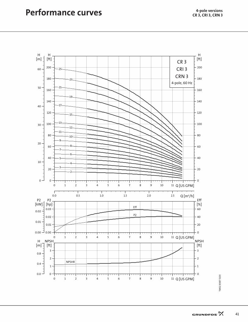
R 3
0 1 2 3 4 5 6 7 8 9 10 11 Q [US GPM]
0
20
40
60
80
100
120
140
160
180
200
[ft]H
0.0 0.5 1.0 1.5 2.0 2.5 Q [m³/h]
0
10
20
30
40
50
60
[m]H
0
20
40
60
80
100
120
140
160
180
200
[ft]H
CR 3
4-pole, 60 Hz
CRI 3
CRN 3
-2
-10
-11
-12
-13
-15
-17
-19
-21
-23
-25
-3-4
-5
-6
-7-8
-9
0 1 2 3 4 5 6 7 8 9 10 11 Q [US GPM]
0.00
0.01
0.02
0.03
[hp]P2
0
20
40
60
Eff[%]
0.00
0.01
0.02
[kW]P2
Eff
P2
0 1 2 3 4 5 6 7 8 9 10 11 Q [US GPM]
0
1
2
3
[ft]NPSH
0
1
2
3
[ft]NPSH
0.0
0.4
0.8
[m]H
NPSHR
Performance curves 4-pole versionsCR 3, CRI 3, CRN 3

42
Performance curves 4-pole versionsCR 5, CRI 5, CRN 5
TM0
2 83
88 5
103C
R 5
0 2 4 6 8 10 12 14 16 18 20 22 Q [US GPM]
0
20
40
60
80
100
120
140
160
180
200
[ft]H
0.0 0.5 1.0 1.5 2.0 2.5 3.0 3.5 4.0 4.5 5.0 Q [m³/h]
0
10
20
30
40
50
60
[m]H
0
20
40
60
80
100
120
140
160
180
200
[ft]H
CR 5
4-pole, 60 Hz
CRI 5
CRN 5
-10-11
-12
-13
-14-15
-16
-18
-2
-20
-22
-24
-3
-4
-5
-6
-7
-8-9
0 2 4 6 8 10 12 14 16 18 20 22 Q [US GPM]
0.00
0.01
0.02
0.03
0.04[hp]P2
0
20
40
60
80
Eff[%]
0.00
0.01
0.02
[kW]P2
P2
Eff
0 2 4 6 8 10 12 14 16 18 20 22 Q [US GPM]
0
1
2
3
4[ft]
NPSH
0
1
2
3
4[ft]
NPSH
0.0
0.4
0.8
1.2[m]H
NPSHR
43
TM0
2 83
89 5
103C
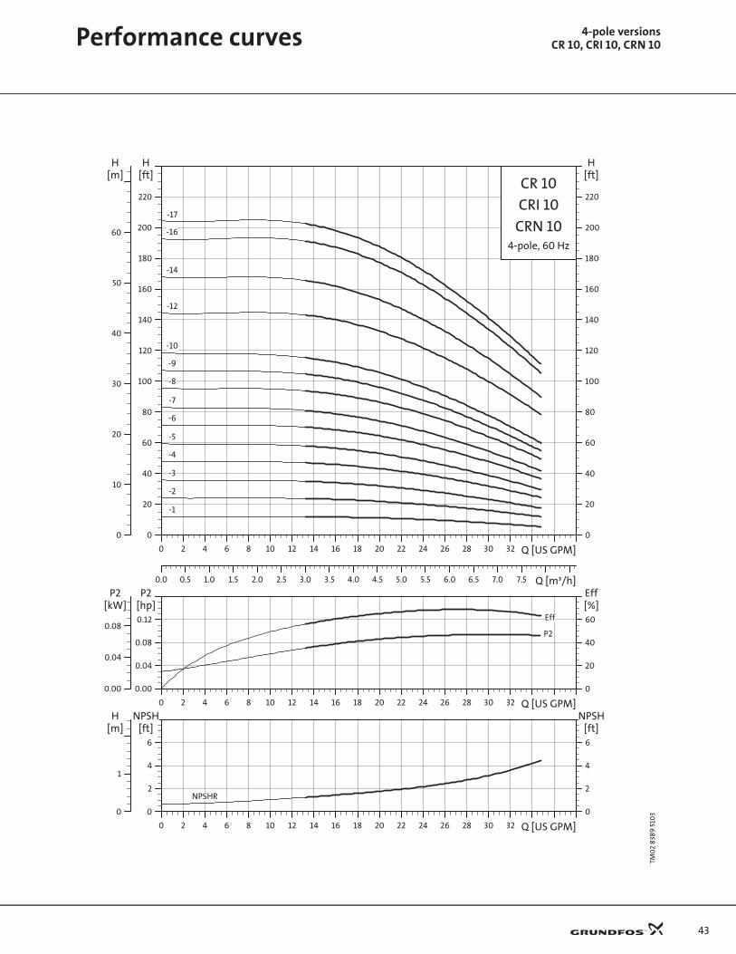
R 1
0
0 2 4 6 8 10 12 14 16 18 20 22 24 26 28 30 32 Q [US GPM]
0
20
40
60
80
100
120
140
160
180
200
220
[ft]H
0.0 0.5 1.0 1.5 2.0 2.5 3.0 3.5 4.0 4.5 5.0 5.5 6.0 6.5 7.0 7.5 Q [m³/h]
0
10
20
30
40
50
60
[m]H
0
20
40
60
80
100
120
140
160
180
200
220
[ft]H
CR 10
4-pole, 60 Hz
CRI 10
CRN 10
-1
-10
-12
-14
-16
-17
-2
-3
-4
-5
-6
-7
-8
-9
0 2 4 6 8 10 12 14 16 18 20 22 24 26 28 30 32 Q [US GPM]
0.00
0.04
0.08
0.12
[hp]P2
0
20
40
60
Eff[%]
0.00
0.04
0.08
[kW]P2
Eff
P2
0 2 4 6 8 10 12 14 16 18 20 22 24 26 28 30 32 Q [US GPM]
0
2
4
6
[ft]NPSH
0
2
4
6
[ft]NPSH
0
1
[m]H
NPSHR
Performance curves 4-pole versionsCR 10, CRI 10, CRN 10
44
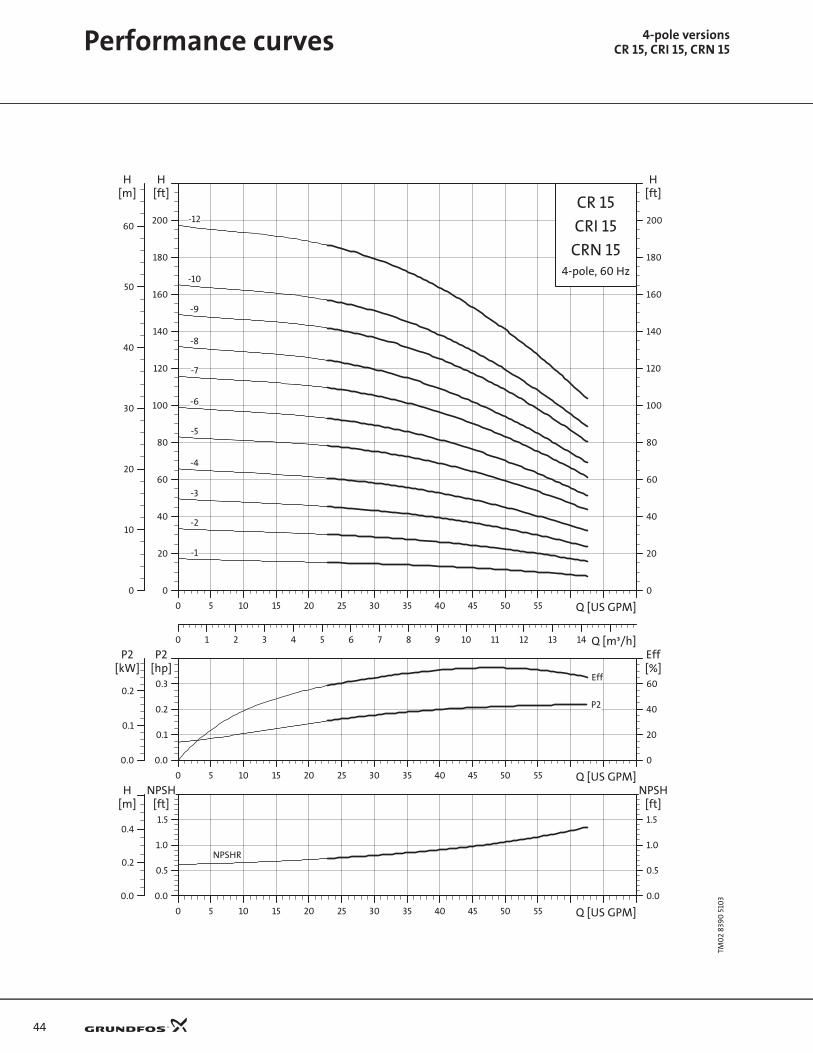
Performance curves 4-pole versionsCR 15, CRI 15, CRN 15
TM0
2 83
90
510
3CR
15
0 5 10 15 20 25 30 35 40 45 50 55 Q [US GPM]
0
20
40
60
80
100
120
140
160
180
200
[ft]H
0 1 2 3 4 5 6 7 8 9 10 11 12 13 14 Q [m³/h]
0
10
20
30
40
50
60
[m]H
0
20
40
60
80
100
120
140
160
180
200
[ft]H
CR 15
4-pole, 60 Hz
CRI 15
CRN 15
-1
-10
-12
-2
-3
-4
-5
-6
-7
-8
-9
0 5 10 15 20 25 30 35 40 45 50 55 Q [US GPM]
0.0
0.1
0.2
0.3
[hp]P2
0
20
40
60
Eff[%]
0.0
0.1
0.2
[kW]P2
P2
Eff
0 5 10 15 20 25 30 35 40 45 50 55 Q [US GPM]
0.0
0.5
1.0
1.5
[ft]NPSH
0.0
0.5
1.0
1.5
[ft]NPSH
0.0
0.2
0.4
[m]H
NPSHR

45
TM0
2 83
91
510
3CR
20
0 5 10 15 20 25 30 35 40 45 50 55 60 65 70 Q [US GPM]
0
20
40
60
80
100
120
140
160
180
[ft]H
0 1 2 3 4 5 6 7 8 9 10 11 12 13 14 15 16 17 Q [m³/h]
0
10
20
30
40
50
[m]H
0
20
40
60
80
100
120
140
160
180
[ft]H
CR 20
4-pole, 60 Hz
CRI 20
CRN 20
-1
-10
-2
-3
-4
-5
-6
-7
-8
0 5 10 15 20 25 30 35 40 45 50 55 60 65 70 Q [US GPM]
0.0
0.1
0.2
0.3
[hp]P2
0
20
40
60
Eff[%]
0.0
0.1
0.2
[kW]P2
P2
Eff
0 5 10 15 20 25 30 35 40 45 50 55 60 65 70 Q [US GPM]
0
2
4
6
8[ft]
NPSH
0
2
4
6
8[ft]
NPSH
0
1
2
[m]H
NPSHR
Performance curves 4-pole versionsCR 20, CRI 20, CRN 20

46
Performance curves 4-pole versionsCR 32, CRN 32
TM0
2 83
92
510
3CR
32
0 10 20 30 40 50 60 70 80 90 100 Q [US GPM]
0
20
40
60
80
100
120
140
160
180
200
220
[ft]H
0 2 4 6 8 10 12 14 16 18 20 22 24 Q [m³/h]
0
10
20
30
40
50
60
[m]H
0
20
40
60
80
100
120
140
160
180
200
220
[ft]H
CR 32
4-pole, 60 Hz
CRN 32-10-2
-9
-9-2
-8
-8-2
-7
-7-2
-6
-6-2
-5
-5-2
-4
-4-2
-3
-3-2
-2 -2-1
-2-2
-1-1 -1
0 10 20 30 40 50 60 70 80 90 100 Q [US GPM]
0.0
0.2
0.4
0.6
0.8[hp]P2
0
20
40
60
80[%]Eff
0.0
0.2
0.4
[kW]P2
P2 2/3P2 1/1Eff
0 10 20 30 40 50 60 70 80 90 100 Q [US GPM]
0
2
4
6
8[ft]
NPSH
0
2
4
6
8[ft]
NPSH
0
1
2
[m]H
NPSHR
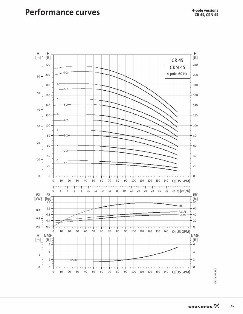
47
TM0
2 83
93
510
3CR
45
0 10 20 30 40 50 60 70 80 90 100 110 120 130 140 Q [US GPM]
0
20
40
60
80
100
120
140
160
180
200
220
[ft]H
0 2 4 6 8 10 12 14 16 18 20 22 24 26 28 30 32 34 Q [m³/h]
0
10
20
30
40
50
60
[m]H
0
20
40
60
80
100
120
140
160
180
200
220
[ft]H
CR 45
4-pole, 60 Hz
CRN 45-7
-7-2
-6
-6-2
-5
-5-2
-4
-4-2
-3
-3-2
-2
-2-2
-1-1-1
0 10 20 30 40 50 60 70 80 90 100 110 120 130 140 Q [US GPM]
0.0
0.4
0.8
1.2
1.6[hp]P2
0
20
40
60
80[%]Eff
0.0
0.4
0.8
[kW]P2
P2 2/3P2 1/1
Eff
0 10 20 30 40 50 60 70 80 90 100 110 120 130 140 Q [US GPM]
0
2
4
6
[ft]NPSH
0
2
4
6
[ft]NPSH
0
1
[m]H
NPSHR
Performance curves 4-pole versionsCR 45, CRN 45
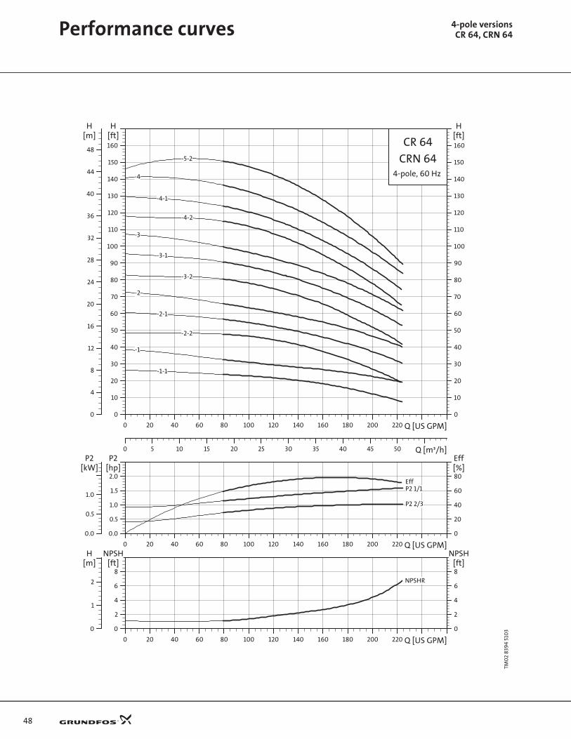
48
Performance curves 4-pole versionsCR 64, CRN 64
TM0
2 83
94
510
3CR
64
0 20 40 60 80 100 120 140 160 180 200 220 Q [US GPM]
0
10
20
30
40
50
60
70
80
90
100
110
120
130
140
150
160
[ft]H
0 5 10 15 20 25 30 35 40 45 50 Q [m³/h]
0
4
8
12
16
20
24
28
32
36
40
44
48
[m]H
0
10
20
30
40
50
60
70
80
90
100
110
120
130
140
150
160
[ft]H
CR 64
4-pole, 60 Hz
CRN 64
-1-1
-1
-2-2
-2-1
-2
-3-2
-3-1
-3
-4-2
-4-1
-4
-5-2
0 20 40 60 80 100 120 140 160 180 200 220 Q [US GPM]
0.0
0.5
1.0
1.5
2.0[hp]P2
0
20
40
60
80[%]Eff
0.0
0.5
1.0
[kW]P2
P2 1/1
P2 2/3
Eff
0 20 40 60 80 100 120 140 160 180 200 220 Q [US GPM]
0
2
4
6
8[ft]
NPSH
0
2
4
6
8[ft]
NPSH
0
1
2
[m]H
NPSHR
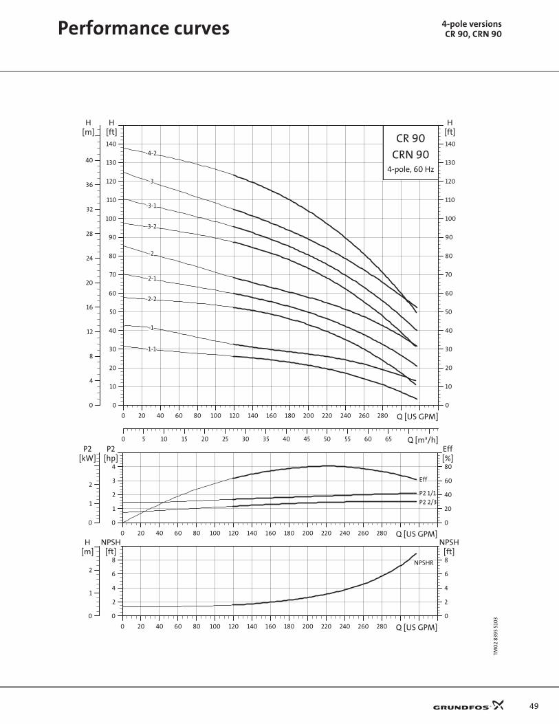
49
TM0
2 83
95
510
3CR
90
0 20 40 60 80 100 120 140 160 180 200 220 240 260 280 Q [US GPM]
0
10
20
30
40
50
60
70
80
90
100
110
120
130
140
[ft]H
0 5 10 15 20 25 30 35 40 45 50 55 60 65 Q [m³/h]
0
4
8
12
16
20
24
28
32
36
40
[m]H
0
10
20
30
40
50
60
70
80
90
100
110
120
130
140
[ft]H
CR 90
4-pole, 60 Hz
CRN 90
-1
-1-1
-2
-2-1
-2-2
-3
-3-1
-3-2
-4-2
0 20 40 60 80 100 120 140 160 180 200 220 240 260 280 Q [US GPM]
0
1
2
3
4[hp]P2
0
20
40
60
80[%]Eff
0
1
2
[kW]P2
P2 1/1P2 2/3
Eff
0 20 40 60 80 100 120 140 160 180 200 220 240 260 280 Q [US GPM]
0
2
4
6
8[ft]
NPSH
0
2
4
6
8[ft]
NPSH
0
1
2
[m]H
NPSHR
Performance curves 4-pole versionsCR 90, CRN 90

50

51

Grundfos Pumps Corporation17100 W. 118th TerraceOlathe, KS 66061Telephone 913 227 3400Fax: 913 227 3500
www.grundfos.com
Grundfos Canada, Inc.2941 Brighton RoadOakville, Ontario L6H 6C9 CanadaTelephone: 905 829 9533Fax: 905 829 9512
Bombas Grundfos de Mexico, S.A. de C.V.Boulevard TLC #15Parque Stiva AeropuertoApodaca, N.L. 66600 Mexico Telephone: 52 81 8144 4000 Fax: 52 81 8144 4010
Being responsible is our foundation
Thinking ahead makes it possible
Innovation is the essence
L-CR-PG-002 02/05USRepl. L-CR-PG-002 2/04
Subject to alterations