Embed Size (px)
Citation preview

Calibration of Phasor Measurement Unit
at NIST
Y. Tang, G.N. Stenbakken, Member, IEEE and A. Goldstein
Abstract1 — Phasor Measurement Units (PMUs) are being deployed on electric power grids to
monitor their static and dynamic behavior. The information they gather is important to detect
problems on these systems and to prevent blackouts. The PMUs require time synchronization of
the data taken across the grids. This is done using Coordinated Universal Time (UTC) usually
derived from the Global Positioning System (GPS). This paper describes the basic operating
principles of PMUs and their time requirements to estimate absolute phase angles. A National
Institute of Standards and Technology (NIST) PMU calibration system that tests PMU
performance necessary to meet the IEEE synchrophasor standard requirements is discussed. The
calibration of voltage, current and time measurements for the NIST PMU test system is
described. The total vector error (TVE) of the NIST PMU test system is estimated to be 0.05 %.
A comparison between the NIST PMU test system and a prototype commercial PMU calibrator
was performed to assure traceability of relevant electrical measurements and time measurement.
1 Manuscript received June 29, 2012. This work was performed at NIST in the Quantum Measurement Metrology
Division, Physical Measurement Laboratory, U.S. Department of Commerce, not subject to copyright in the United
States.
Y. Tang is with the National Institute of Standards and Technology, Gaithersburg, MD 20899 USA (e-mail: yi-
G.N. Stenbakken is with GNS Consulting, Potomac, MD 20854 USA (e-mail: [email protected]).
A. Goldstein is with Fluke Calibration, Everett, WA, 98203, USA (e-mail: [email protected]).

Index Terms — Calibration, Coordinated Universal Time (UTC), Global Positioning System
(GPS), Phase Measurement Unit (PMU), total vector error (TVE), traceability, uncertainty.
I. INTRODUCTION
The electric power transmission network is being upgraded with new information
technologies to more rapidly monitor the state of the grid. With the planned addition of many
new energy sources, such as solar, wind, and others, the power grid observability has become
important to minimizing future blackouts.
One instrument type that provides high observability of the grid state is Phasor
Measurement Units (PMUs). Hundreds of PMUs have been deployed in the U.S. power grid and
worldwide in the past few years. In order to observe the health of the power grid, the
measurements made by the PMUs must be time synchronized. This is normally done using
Coordinated Universal Time (UTC) derived from the Global Positioning System (GPS). The
standard for PMUs, IEEE C37.118.1-2011 [1], was recently updated. This standard defines the
uncertainty requirements for the PMUs in terms of Total Vector Error, TVE. This error
measurement assures that compliant PMUs have limited uncertainty in both their magnitude and
time-synchronization errors. The standard limits the TVE uncertainty for the phasors, the
frequency errors, FE, for the frequency estimates, and the RFE, rate-of-change-of-frequency
(ROCOF) error for various power signal conditions.
The synchrophasor representation X of a signal x(n) is the complex value given by
Equation (1).
( √ ⁄ ) (1)

where √ ⁄ is the root mean square (rms) value of the signal x(n) and φ(n) is its
instantaneous phase angle relative to a cosine function at nominal system frequency
synchronized to UTC. TVE(n) is defined as shown in Equation (2):
√( ̂ )
( ̂ )
( ) (2)
where ̂ and ̂ are the sequences of estimates given by the unit under test, and
and are the sequences of theoretical values of the input signal at the instants of time (n)
assigned by the unit to those values described in [2].
This paper will describe how the NIST PMU test system makes traceable magnitude and
phase calibration for ac signals under static and dynamic conditions. Also, calibrated are the
frequency and rate of change of frequency measurements made by the PMUs. The PMU test
results are then compared to the performance requirements defined in the IEEE PMU standard.
To improve traceability of PMU measurements across the many test systems a PMU round robin
using a stable PMU is being planned.
II. NIST PMU TEST SYSTEM
Figure 1 shows a block diagram of the NIST PMU test system. The system is based on
generating stable test signals for a PMU to measure [3]. These test signals are measured by the
NIST test system as they are applied to the PMU. The traceability of the NIST PMU test system
consists of showing traceability of the sampling system to national standards. Note that this
includes testing of the software used to estimate the phasor values.

A. Hardware
The Synchronized Generation and Sampling System are housed in a National Instruments
PXI2 chassis. Two cards in the system are used to generate sampling clock signals for the
generation and sampling cards of 18 MHz that is synchronized with UTC via the GPS signals.
This provides a very stable clock for the system and prevents jitter in the generation and
sampling caused by separate clocking. This frequency was chosen to allow the generation of
both 50 Hz and 60 Hz power signals with an integer number of samples per cycle.
Six channels of 16-bit digital to analog (D/A) generate the source signals for the three
voltage and three current channels. These have a maximum output of ±10 V. These signals have
a strobe rate of between 48 kHz to 500 kHz for various applications. When generating PMU test
signals the generation cards usually run at 48 k samples per second (sps). A single pole filter
with a 3 dB cutoff of approximately 5 kHz is used on all six channels to reduce the sampling
steps.
Three voltage amplifiers with a gain of 21 are used to generate the nominal 70 V rms
signals for the PMU tests. Three transconductance amplifiers with a transconductance of 1 A per
1 V are used to generate the nominal 5 A rms signals for the PMU tests.
The three resistive voltage attenuators have a nominal ratio of 21-to-1. They are NIST
built and calibrated using low temperature coefficient, TC, resistors and are compensated to have
flat frequency response from dc to over 5 kHz and constant time delay over that frequency range.
The three current transformers (CTs) are NIST built two stage [4] designs to give stable
2 Certain commercial equipment, instruments, or materials are identified in this report to facilitate understanding.
Such identification does not imply recommendation or endorsement by NIST, nor does it imply that the materials or
equipment that are identified are necessarily the best available for the purpose.

transimpedance and time delays over that same frequency range. The CTs have a ratio of 10 to1.
Ten low TC 10 ohm resistors in parallel are used for the secondary burden and one 1 ohm low
TC resistor is used for the tertiary burden.
The design of using the sampling of signals to the device-under-test, DUT, as the
calibration reference allows this same system to be used to calibrate PMU calibrators. For such
calibrations the NIST voltage and current generators are replaced with the signals from the
commercial PMU calibrator. A signal from the commercial PMU calibrator to a digital input on
the NIST calibrator is used to coordinate the operation of the two systems.
Synchronization of the system to UTC is maintained with a clock synchronized to UTC
via reception of a GPS signal. The NIST test system is located in an underground building so the
reception of the GPS signal is made more difficult. The reception is performed by use of a down
up convertor. Near the GPS antenna a down convertor changes the GPS signal band from the
nominal 1.575 42 GHz to an intermediate frequency (IF) of 4.092 MHz from the beating with a
local oscillator (LO) of 16.368 MHz. The lower frequency signal is transmitted with much lower
loss to the underground location using approximately 150 m of cable. In the testing laboratory
the signal band is upconverted to the nominal 1.575 42 GHz signals. This signal is applied to the
GPS clock and to the PMUs if required.
The signals from the GPS /clock used by the NIST test system are the 1 pulse per second
(1 PPS) signal, an InterRange Instrumentation Group Time Code Format B [5] (IRIG-B) and a
10 MHz signal. The 1 PPS signal is used to synchronize the start of the signal generation and the
signal sampling. This hardware synchronization assures that the generation and sampling rate
signals are synchronized to the clock reference signal. The IRIG-B signal is used to determine
the second of the year to which the test is synchronized. The 10 MHz signal is used as described

above to generate the 18 MHz clock reference signal.
B. Software
The PMU testing software is written in LabVIEW2. Most critical of the software are the
four analysis algorithms used to translate the sampled data into phasor estimates that are used to
calibrate the DUT.
As indicated above, the same voltage and current signals applied to the DUT are sampled
by the Signal Generation and Sampling System. This system also receives the timestamped
phasor information from the DUT. This includes all the phasors programmed into the DUT and
the frequency and rate-of-change-of-frequency (ROCOF) estimates. For testing purposes the
signal samples are used to develop accurate timestamped estimates for these signals based on the
calibration of the NIST test system. This calibration is described more fully in a section below.
The standard specifies various test signal conditions.
The power signal conditions that are prescribed in the updated Synchrophasor Standard,
C37.118.1-2011 [1], can be divided into four categories. First are the steady state conditions with
various signal frequencies, phases, and magnitudes and the addition of harmonic and
interharmonic signals. Second are the time changing conditions with amplitude, phase, and
ROCOF steps. The ROCOF step is usually referred to as the frequency ramp test. The third and
fourth categories are parts of the amplitude and phase modulation tests. Different analysis
algorithms are used depending on the frequency of the modulation.
All of the analysis algorithms are variations of fitting algorithms. The differences
between these algorithms are the functions used for the fitting. Since the generation and
sampling are synchronized using a well-known frequency source and timing system, the

frequency and ROCOF of the steady state signals are well defined. The steady state algorithm
uses a fitting function that includes one or two signal frequencies. The fitting function includes
sine and cosine functions for the one or two signal frequencies along with a dc component. These
allow for estimating the magnitude and phases of the one or two signals. The two signal
frequencies functions are used for the harmonic and interharmonic test. The well-known
frequency and ROCOF are used for determining the FE and RFE of the DUT. This algorithm
always selects samples such that timestamp is at the center of the sampling window. The number
of cycles of the fundamental used in each sampling window is programmable. Normally this is
set at three cycles.
The fitting functions used for the time changing conditions are very similar to those for
the steady state test, except that they include a rate of change parameter for defining the
functions. This algorithm uses selection of the samples to avoid fitting across a parameter step
[6]. The data before or after the step are used. The sampling windows for timestamps near the
steps are not in the center of the sampling window. Figure 2 shows the relation between the data
samples windows and the timestamps near a magnitude step, which occurs at tstep. Data sample
windows are shown for timestamps tx to tx+4. The data sample windows for timestamps up to and
including tx are centered on the respective timestamps. The window for timestamps tx+1 and tx+2
use the same data, all using data before the magnitude step. The timestamps tx+1 and tx+2 are not
centered in this window. The window for timestamp tx+3 uses data after the step. The timestamp
tx+3 is not centered in that window. The windows for timestamps tx+4 and later all use windows
centered on the respective timestamps. This algorithm allows for iterating on the signal
frequency to achieve a fit with small residuals. This feature is used for the frequency ramp test to
determine the frequency at each timestamp. The reference ROCOF value used is the predefined

one used to generate the signals.
As stated above the analysis algorithms used for the modulation tests depend on the
frequency of the signal modulation. For modulations below about 1 Hz a Taylor expansion
algorithm is used [7]. The fitting functions used in this algorithm include the sine and cosine
functions for the nominal signal frequencies as the algorithms above. They also include higher
order time derivatives of these functions. The sample windows are centered on the timestamps.
The fit for the first time derivative functions are used to estimate the signal frequency at the
timestamps and the second time derivative functions are used to estimate the signal ROCOF at
the timestamps. Only third order functions are use in tests, i.e., first and second time derivatives
of the sine and cosine functions.
For modulation frequencies above approximately 1 Hz the three waveform fitting
algorithm is used [7]. This algorithm uses an iterative approach to fit the window of samples to
three time varying sinewaves. The iterations allow for fitting the frequency and phase of the
modulation from which the frequency and ROCOF are estimated.
III. CALIBRATION OF NIST PMU TEST SYSTEM
The NIST PMU test system is calibrated using calibrated test input signals. The method
uses signals synchronized with UTC and with constant magnitude. The NIST test system
algorithms are used to estimate the magnitude and absolute phase angle of the signals. The
magnitudes and phases of the test signals are determined using laboratory test equipment with a
traceable history.
The magnitude errors of the NIST PMU test system are measured using a DVM and the
Swerlein algorithm [8, 9]. This requires a DVM with modeled dc sampling and a dc calibration.
The meter is calibrated with a traceable source with uncertainty of 2 parts in 106. Then the

uncertainty of the meter is less than 5 parts in 106 for readings up to 100 Hz and 100 V rms. This
is used for the voltage channels and the voltage out of the CTs. This calibrates the voltage
attenuators, the voltage A/Ds, and the fitting algorithms. The magnitude and phase errors of the
CTs are traceable back to the NIST calculable shunt [10]. The system used to do that is described
in an intercomparison published in 2005 [11]. The gain and phase errors are determined from 40
Hz up to 10 kHz. The phase errors of the voltage attenuators are done by assuring the flat gain
errors of the attenuators over the 50 Hz to 3 kHz range.
PMU calibrations are somewhat unique in that in addition to determining phase errors of
the channels, the time alignment of the samples to UTC must be determined. Figure 3 shows the
NIST system time alignment test setup. It consists of using an oscilloscope to compare the zero
crossings of the generated waveforms with a 1 PPS signal from a GPS clock. The GPS clock
used in the NIST PMU calibration system has an uncertainty of less than ±45 ns between the
pulse signal and UTC. Several factors affect the accuracy of this calibration. These include how
the amplitude noise on the signal affects the ability of the oscilloscope to resolve the zero
crossings, the phase shift of the current transformer (CT) used to convert the current to a voltage,
and the dc offset and distortion of the signals.
The calibration procedures used minimize several of the errors mentioned above. The
NIST sampling system is acting as a PMU. It samples the same signals being sent to the PMU
under test during PMU calibrations. Unlike commercial PMUs the NIST system can be set to use
nominal signal frequencies other than 50 Hz and 60 Hz. This feature is used during the NIST
system phase calibrations. For the phase calibration the nominal signal frequencies of the
analysis system and the signal frequencies of the generated signals are set to frequencies from
200 Hz to 4 kHz. These higher frequency signals reduce the timing uncertainty due to the

amplitude noise on the signal and oscilloscope noise. The oscilloscope is set to amplitude over-
range to display a higher voltage-to-time slope for these measurements.
IV. TRACEABILITY
The traceability of measurements requires control of many factors in the calibration
process. The test equipment used must be traceable to reference standards, and the test
procedures and staffs need to be qualified. This will better assure that PMUs tested by all of them
will have the same behavior.
Inaccurate PMU calibration can lead to selecting PMUs that do not behave the same,
which can have serious financial consequences to electric power utilities as well as reliability and
safety consequences. There have been hundreds of PMUs deployed in the US power grid and
several PMU calibration systems deployed in US industry, universities and research laboratories.
The traceability of these PMU calibrations to a recognized standard organization (for example, to
NIST or other national metrology institutes) has not been demonstrated. The NIST calibration
system has an estimated one sigma uncertainty in magnitude of less than 0.01 % and a timing
uncertainty of less than 0.3 μs. This gives a three sigma total vector error, TVE, uncertainty of
0.05 %.
A prototype of commercial PMU calibration system has been developed. It includes a 3-
phase electrical power standard, a GPS receiver to provide reference frequency and UTC time, a
PMU calibrator device to time align the voltage and current phases of the power standard, and a
MS2 Windows™ computer to receive the measurements from the PMU under test and perform
analysis. The PMU calibration software is the control interface to the PMU calibrator to perform
various tests defined in the C37.118.1-2011. A comparison between the NIST PMU calibration
system and the prototype PMU calibration system was performed to evaluate its performance

and verify all measurements traceable to national standards with uncertainties required to
perform PMU calibration.
As stated above the NIST system samples the voltage and current signals going to the
PMU under test and uses that data to estimate the correct PMU response values. The prototype
PMU calibration system similarly generates test signals for a PMU under test and the estimated
proper PMU response values called reference PMU values. These two systems were compared
using the test set-up shown in Figure 4. The two systems were time coordinated by having the
prototype PMU calibration system send a trigger signal to the NIST system a few milliseconds
before the beginning of a test. Then the NIST system triggers on the next PPS signal and samples
the voltage and current signals as they were going to a PMU under test. These samples are used
to estimate the proper PMU test results. After the test the NIST estimates are compared directly
with the prototype PMU calibration reference PMU values.
Both the NIST test system and the prototype PMU calibration system are designed to
work while connected to a PMU sending IEEE C37.118 messages. A PMU that is configured as
two PMUs was used to provide phasor messages to both test systems as shown in Figure 4.
Independent analysis tools at the prototype PMU calibration and NIST determine TVE
and other parameters. The differences between the NIST measurements and reference provided
by the power source of the prototype PMU calibration system are calculated and analyzed,
including the magnitudes and phases of voltages and currents for all 3 phases. Figure 5 shows the
current amplitude differences of three phases between the NIST and the prototype PMU
calibration system in a comparison of a steady test at 60 Hz with 70 V and 5 A. The
measurements were made at 20 frames per second for 5 s. The current phase differences as well
as the amplitude and phase differences in voltage measurements were also recorded. The
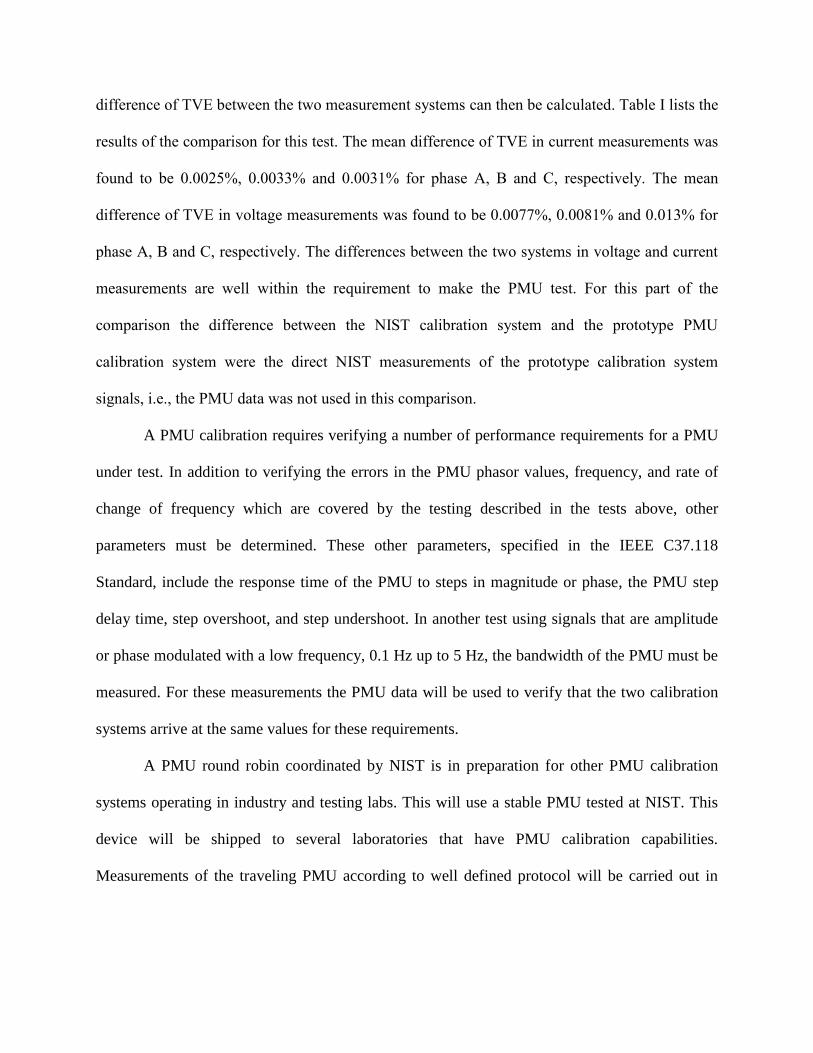
difference of TVE between the two measurement systems can then be calculated. Table I lists the
results of the comparison for this test. The mean difference of TVE in current measurements was
found to be 0.0025%, 0.0033% and 0.0031% for phase A, B and C, respectively. The mean
difference of TVE in voltage measurements was found to be 0.0077%, 0.0081% and 0.013% for
phase A, B and C, respectively. The differences between the two systems in voltage and current
measurements are well within the requirement to make the PMU test. For this part of the
comparison the difference between the NIST calibration system and the prototype PMU
calibration system were the direct NIST measurements of the prototype calibration system
signals, i.e., the PMU data was not used in this comparison.
A PMU calibration requires verifying a number of performance requirements for a PMU
under test. In addition to verifying the errors in the PMU phasor values, frequency, and rate of
change of frequency which are covered by the testing described in the tests above, other
parameters must be determined. These other parameters, specified in the IEEE C37.118
Standard, include the response time of the PMU to steps in magnitude or phase, the PMU step
delay time, step overshoot, and step undershoot. In another test using signals that are amplitude
or phase modulated with a low frequency, 0.1 Hz up to 5 Hz, the bandwidth of the PMU must be
measured. For these measurements the PMU data will be used to verify that the two calibration
systems arrive at the same values for these requirements.
A PMU round robin coordinated by NIST is in preparation for other PMU calibration
systems operating in industry and testing labs. This will use a stable PMU tested at NIST. This
device will be shipped to several laboratories that have PMU calibration capabilities.
Measurements of the traveling PMU according to well defined protocol will be carried out in

these laboratories. The results of the PMU testing by NIST and the participating laboratories will
be compared.
V. IMPROVEMENT OF PMU PERFORMANCE
The benefits of PMU testing can be seen from the changes in PMU performance
following the feedback to manufacturers of their PMUs’ test results. Figure 6 shows the failed
out-of-band interference test results for the first test on a PMU. The errors should be below 1 %
TVE for all out-of-band frequencies. Following an update of the PMU’s firmware by the PMU
manufacturer, the out-of-band performance for a retest is as shown in Figure 7, which uses the
same vertical scale for comparison. All the test results are below the 1 % TVE limit. The PMU
passed this test and all other IEEE C37.118 requirements. This improved performance has
happened for several PMUs tested at NIST following feedback of the results to the
manufacturers.
VI. CONCLUSION
NIST has developed a PMU calibration system. The measurements in voltage, current
and phase made by the NIST PMU calibration system have been calibrated against the reference
traceable to the national standards. The NIST PMU calibration system has an estimated TVE
uncertainty of 0.05%. This uncertainty is 5 times smaller than the requirements of C37.118.1 for
TVE of the PMU test system. The system is being used for testing of PMUs. The NIST PMU
calibration system has been compared with a prototype PMU calibration system. The difference
between the two systems for PMU test for measurements in voltage, current and their phases are
well within the requirements for PMU calibration purpose. The NIST system will also be used in
a planned round robin to improve traceability of PMUs.

Acknowledgement
The authors would like to thank B. C. Waltrip for his assistance for calibrating CTs.
REFERENCES
[1] "IEEE Standard for Synchrophasor Measurements for Power Systems," IEEE Std
C37.118.1-2011 (Revision of IEEE Std C37.118-2005), pp.1-61, Dec. 28, 2011.
[2] Y. Tang and G.N. Stenbakken, “Calibration of Phasor Measurement Unit at NIST,”
Digest of Conf. on Precision Electromagnetic Measurements (CPEM2012), accepted,
July 1 - July 6, 2012, Washington DC, USA.
[3] G.N. Stenbakken, M. Zhou; “Dynamic Phasor Measurement Unit Test System,” IEEE
Power Engineering Society General Meeting, 2007, 24-28 June 2007, p 8.
[4] T.M. Souders, “Wide-Band Two-Stage Current Transformers of High Accuracy,” IEEE
Transactions on Instrumentation and Measurement, vol.21, no.4, pp.340-345, Nov. 1972.
[5] Range Commanders Council, IRIG Standard 200-04, Sept. 2004.
[6] J. Ren, M. Kezunovic, and G.N. Stenbakken, “Dynamic characterization of PMUs using
step signals,” IEEE Power & Energy Society General Meeting, 2009. PES '09, pp.1-6,
26-30, July 2009.
[7] G.N. Stenbakken, T. Nelson, M. Zhou, and V. Centeno, “Reference Values for Dynamic
Calibration of PMUs,” Proceedings of the 41st Hawaii International Conference on
System Sciences, pp1-6, 7-10 Jan. 2008.
[8] R.L. Swerlein, “A 10 ppm Accurate Digital AC Measurement Algorithm,” Proceedings
NCSL, pp. 17-36, Albuquerque, USA, Aug. 1991.

[9] G.A. Kyriazis, and R. L. Swerlein, “Evaluation of uncertainty in AC voltage
measurement using a digital voltmeter and Swerlein's algorithm,” Conference on
Precision Electromagnetic Measurements, Conference Digest 2002, pp. 24- 25, 2002.
[10] O.B. Laug, T.M. Souders, and B.C. Waltrip, “A Four-Terminal Current Shunt with
Calculable AC Response, NIST Tech. Note No. 1462,” NIST, Gaithersburg, MD.
[11] E. So, D. Angelo, T. Tsuchiyama, T. Tadokoro, B.C. Waltrip, and T.L Nelson,
“Intercomparison of calibration systems for AC shunts up to audio frequencies,” IEEE
Transactions on Instrumentation and Measurement, , vol.54, no.2, pp. 507- 511, April
2005.

Figure 1. Block diagram of NIST PMU test system. IRIG-B stands for the Inter-Range
Instrumentation Group time code B. CT refers to Current Transformer.
Figure 2. Relation between data sample windows for timestamps near a magnitude step.
Windows shown are for data samples over three cycles of the fundamental signal. Timestamps
reflect a reporting rate the same as the fundamental frequency. The magnitude step occurs at time
tstep.

Figure 3. Block diagram of NIST magnitude and phase calibration test setup where DVM stands
for digital voltmeter and CT for current transformer.
Figure 4. Setup for comparison between the NIST and the prototype PMU calibration systems.
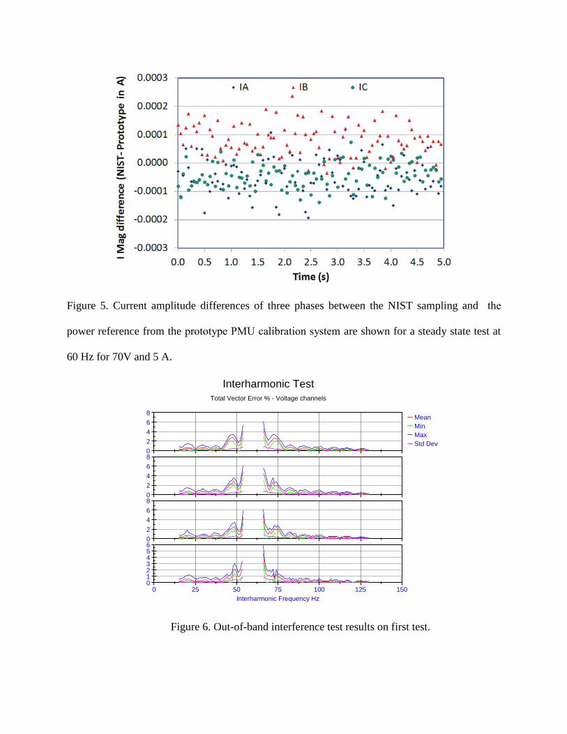
Figure 5. Current amplitude differences of three phases between the NIST sampling and the
power reference from the prototype PMU calibration system are shown for a steady state test at
60 Hz for 70V and 5 A.
Figure 6. Out-of-band interference test results on first test.
0
2
4
6
8
VC
TV
E %
0
2
4
6
8
VA
TV
E % Mean
Min
Max
Std Dev
0 25 50 75 100 125 150
Interharmonic Frequency Hz
0123456
V1
TV
E %
0
2
4
6
8
VB
TV
E %
Interharmonic Test
Total Vector Error % - Voltage channels
Figure IH1. Total Vector Error (TVE) for the voltage channels VA (top), VB, VC, and V1 (bottom)
versus interharmonic frequency (10 % of fundamental magnitude).
IH12_4_24_09Fcut

Figure 7. Out-of-band interference test results on second test.
TABLE I
CURRENT COMPARISON RESULTS BETWEEN NIST AND THE PROTOTYPE PMU CALIBRATION
SYSTEMS (ALL TVE IN %)
IA TVE IB TVE IC TVE
Max. 0.0048 0.0058 0.0052
Min. 0.0002 0.0014 0.0009
Mean 0.0025 0.0033 0.0031
STDEV 0.0010 0.0009 0.0010
0
2
4
6
8
VC
TV
E %
0
2
4
6
8
VA
TV
E % Mean
Min
Max
Std Dev
0 25 50 75 100 125 150
Interharmonic Frequency Hz
0
2
4
6
8
V1
TV
E %
0
2
4
6
8
VB
TV
E %
Interharmonic Test
Total Vector Error % - Voltage channels
Figure IH1. Total Vector Error (TVE) for the voltage channels VA (top), VB, VC, and V1 (bottom)
versus interharmonic frequency (10 % of fundamental magnitude).
IH2513_9_3_10

Yi-hua Tang received his Ph.D. in low-temperature physics from the
University of Florida in 1987. He worked in the private sector from 1991 to
1996 in the field of Josephson arrays and voltage standards. He joined the
National Institute of Standards and Technology, Gaithersburg, Maryland in
January 1997 and is now working on the Josephson voltage standard and its applications in
metrology. He is responsible for maintaining the U.S. legal volt and providing for the
dissemination of an internationally consistent and traceable voltage standard tied to the SI units.
His research interest is to develop applications of Josephson technology for dc and ac voltage
metrology. In recent years he is also engaged in the Phasor Measurement Unit (PMU) research to
develop traceable measurement technology for the Smart Grid. He is the recipient of a U.S.
Department of Commerce Gold Medal. Dr. Tang is a member of the American Physical Society.
Gerard Stenbakken (M’71) received his B.S in Physics from the University of
Minnesota in 1964, the M.S. in Physics and the M.S. in electrical engineering
from the University of Maryland in 1969 and 1986, respectively. He started
working at Vitro Laboratories in 1963 and moved to the National Bureau of
Standards (now the National Institute of Standards and Technology) in 1969. His areas of
interest include electric power metrology, semiconductor measurements, sampling metrology,
testing strategies, and magnetic field modeling. He left NIST and formed GNS Consulting in
2009 to do research in power metrology.

Allen Goldstein received his B.S. in Electrical Engineering from the
University of Southern California in 1982. From 1982 to 1987 he served as a
U.S. Naval Submarine Officer. He worked in the private sector focusing on
designing professional and consumer audio and video products based on
emerging international standards. In 2008 he switched his focus to the design of electric power
transmission and distribution products, also based on emerging standards. For the past two years
Allen has been the Technical Project Manager for PMU Calibration at Fluke Calibration in
Everett, Washington.