Embed Size (px)
Citation preview

CPE 201Digital Design
Lecture 25:
Register Transfer Level Design (2)

2
Lecture Outline
• RTL Design Examples

3
Step 1 Example: Laser-Based Distance Measurer
• Example of how to create a high-level state machine to describe desired processor behavior
• Laser-based distance measurement – pulse laser, measure time T to sense reflection– Laser light travels at speed of light, 3*108 m/sec – Distance is thus D = T sec * 3*108 m/sec / 2
Object ofinterest
D
2D = T sec * 3*108 m/sec
sensor
laser
T (in seconds)

4
Step 1 Example: Laser-Based Distance Measurer
• Inputs/outputs– B: bit input, from button to begin measurement– L: bit output, activates laser– S: bit input, senses laser reflection– D: 16-bit output, displays computed distance
sensor
laser
T (in seconds)
Laser-baseddistancemeasurer16
from button
to displayS
L
D
Bto laser
from sensor

5
Step 1 Example: Laser-Based Distance Measurer
• Step 1: Create high-level state machine• Begin by declaring inputs and outputs• Create initial state, name it S0
– Initialize laser to off (L=0)– Initialize displayed distance to 0 (D=0)
Laser-based
distancemeasurer16
from button
to displayS
L
D
Bto laser
from sensor
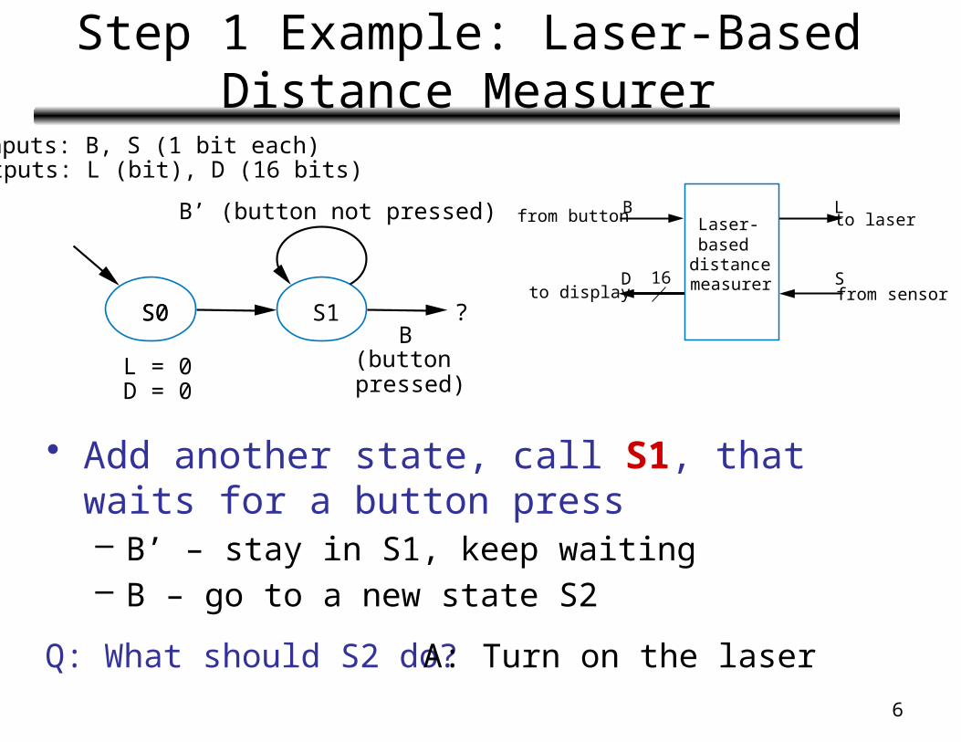
Inputs:B, S(1 bit each)Outputs:L (bit), D (16 bits)
S0 ?
L = 0 (laser off)D = 0 (distance = 0)
6
Step 1 Example: Laser-Based Distance Measurer
• Add another state, call S1, that waits for a button press– B’ – stay in S1, keep waiting– B – go to a new state S2
Inputs: B, S (1 bit each)Outputs: L (bit), D (16 bits)
S0
L = 0D = 0
S1 ?
B’ (button not pressed)
B(buttonpressed)
S0
Q: What should S2 do? A: Turn on the laser
Laser-based
distancemeasurer16
from button
to displayS
L
D
Bto laser
from sensor

7
Step 1 Example: Laser-Based Distance Measurer
• Add a state S2 that turns on the laser (L=1)• Then turn off laser (L=0) in a state S3
S0 S1 S2
L = 0D = 0
L = 1(laser on)
S3
L = 0(laser off)
B’
B
Q: What to do next? A: Start timer, wait to sense reflection
Laser-based
distancemeasurer16
from button
to displayS
L
D
Bto laser
from sensor
Inputs: B, S (1 bit each)Outputs: L (bit), D (16 bits)

8
Step 1 Example: Laser-Based Distance Measurer
• Stay in S3 until sense reflection (S)• To measure time, count cycles while we are in S3
– To count, declare local register Dctr– Increment Dctr each cycle in S3– Initialize Dctr to 0 in S1 (S2 would have been OK too)
to display
Laser-baseddistancemeasurer16
from button
S
L
D
Bto laser
from sensor
Local Registers: Dctr (16 bits)
S0 S1 S2 S3
L = 0D = 0
L = 1 L = 0Dctr = Dctr + 1(count cycles)
Dctr = 0(reset cycle
count)
B’
B
S’ (no reflection)
S (reflection)?
Inputs: B, S (1 bit each)Outputs: L (bit), D (16 bits)

9
Step 1 Example: Laser-Based Distance Measurer
• Once reflection detected (S), go to new state S4– Calculate distance – Assuming clock frequency is 3x10⁸, Dctr holds number
of meters, so D=Dctr/2• After S4, go back to S1 to wait for button again
S0 S1 S2 S3
L = 0D = 0
L = 1 L=0Dctr = Dctr + 1
Dctr = 0
B’ S’
B SD = Dctr / 2
(calculate D)
S4
Local Registers: Dctr (16 bits)Inputs: B, S (1 bit each)Outputs: L (bit), D (16 bits)
to display
Laser-baseddistancemeasurer16
from button
S
L
D
Bto laser
from sensor

10
Step 2: Create a Datapath
• Datapath must– Implement data storage– Implement data computations
• Look at high-level state machine,
do three substepsa) Make data inputs/outputs be datapath inputs/outputs
b) Instantiate declared local registers into the datapath (also instantiate a register for each data output)
c) Examine every state and transition, and instantiate datapath components and connections to implement any data computations
Instantiate: to introduce a new component into a design.

11
Step 2 Example: Laser-Based Distance Measurer
(a) Make data inputs/outputs be datapath inputs/outputs
(b) Instantiate declared registers into the datapath (also instantiate a register for each data output)
(c) Examine every state and transition, and instantiate datapath components and connections to implement any data computations
DatapathDreg_clr
Dctr_clrDctr_cnt
Dreg_ld
Local Registers: Dctr (16 bits)
S0 S1 S2 S3
L = 0D = 0
L = 1 L=0Dctr = Dctr + 1
Dctr = 0
B‘ S‘
B SD = Dctr / 2(calculate D)
S4
load
Q
IDreg: 16-bit
registerQ
Dctr: 16-bitup-counter
16
D
clearclearcount
a
Inputs: B, S (1 bit each)Outputs: L (bit), D (16 bits)

12
Step 2 Example: Laser-Based Distance Measurer
(c) (continued) Examine every state and transition, and instantiate datapath components and connections to implement any data computations
clear
count
clear
load
Q Q
IDctr: 16-bitup-counter
Dreg: 16-bitregister
16
D
Datapath
Dreg_clr
Dctr_clrDctr_cnt
Dreg_ld 16
16
>>1
Local Registers: Dctr (16 bits)
S0 S1 S2 S3
L = 0D = 0
L = 1 L=0Dctr = Dctr + 1
Dctr = 0
B‘ S‘
B SD = Dctr / 2(calculate D)
S4
Inputs: B, S (1 bit each)Outputs: L (bit), D (16 bits)
13
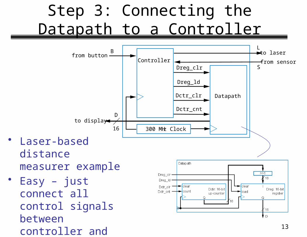
Step 3: Connecting the Datapath to a Controller
• Laser-based distance measurer example
• Easy – just connect all control signals between controller and datapath
300 MHz Clock
D
BL
S
16
to display
from buttonController
to laser
from sensor
Datapath
Dreg_clr
Dreg_ld
Dctr_clr
Dctr_cnt

14
Step 4: Deriving the Controller’s FSM
• FSM has same structure as high-level state machine– Inputs/outputs
all single bits now
– Replace data operations by bit operations using datapath
Inputs: B, SOutputs: L, Dreg_clr, Dreg_ld, Dctr_clr, Dctr_cnt
S0 S1 S2 S3
L = 0 L = 1 L = 0L = 0
B’ S’
B SS4
L = 0
Inputs: B, S (1 bit each)Outputs: L (bit), D (16 bits)Local Registers: Dctr (16 bits)
S0 S1 S2 S3
L = 0D = 0
L = 1 L=0Dctr = Dctr + 1
Dctr = 0
B’ S’
B SD = Dctr / 2(calculate D)
S4
a
Dreg_clr = 1Dreg_ld = 0Dctr_clr = 0Dctr_cnt = 0(laser off)(clear D reg)
Dreg_clr = 0Dreg_ld = 0Dctr_clr = 1Dctr_cnt = 0(clear count)
Dreg_clr = 0Dreg_ld = 0Dctr_clr = 0Dctr_cnt = 0(laser on)
Dreg_clr = 0Dreg_ld = 0Dctr_clr = 0Dctr_cnt = 1(laser off)(count up)
Dreg_clr = 0Dreg_ld = 1Dctr_clr = 0Dctr_cnt = 0(load D reg with Dctr/2)(stop counting)

15
Step 4: Deriving the Controller’s FSM
• Using shorthand notation: if not shown, it’s 0
S0 S1 S2 S3
L = 0 L = 1 L = 0L = 0
B’ S’
B SS4
L = 0Dreg_clr = 1Dreg_ld = 0Dctr_clr = 0Dctr_cnt = 0(laser off)(clear D reg)
Dreg_clr = 0Dreg_ld = 0Dctr_clr = 1Dctr_cnt = 0(clear count)
Dreg_clr = 0Dreg_ld = 0Dctr_clr = 0Dctr_cnt = 0(laser on)
Dreg_clr = 0Dreg_ld = 0Dctr_clr = 0Dctr_cnt = 1(laser off)(count up)
Dreg_clr = 0Dreg_ld = 1Dctr_clr = 0Dctr_cnt = 0(load D reg with Dctr/2)(stop counting)
S0 S1 S2 S3
B’ S’
B SS4
Inputs: B, SOutputs: L, Dreg_clr, Dreg_ld, Dctr_clr, Dctr_cnt
Dreg_clr = 1 Dctr_clr = 1 Dctr_cnt = 1 Dreg_ld = 1L = 1

16
Step 4
• Implement FSM as state register and logic to complete the design
300 MHz Clock
D
B L
S
16to display
from button
Contr
olle
r to laserfrom sensor
Data
path
Dreg_clr
Dreg_ld
Dctr_clr
Dctr_cnt
S0 S1 S2 S3
B’ S’
B SS4
Inputs: B, SOutputs: L, Dreg_clr, Dreg_ld, Dctr_clr, Dctr_cnt
Dreg_clr = 1 Dctr_clr = 1 Dctr_cnt = 1 Dreg_ld = 1L = 1

17
RTL Design Examples and Issues
• We’ll use several more
examples to illustrate RTL design• E.g.: Bus interface
– Master processor can read
register from any peripheral• Each register has unique 4-bit address
– Sets rd=1, A=address– Appropriate peripheral places
register data on 32-bit D lines• Periph’s address provided on Faddr
inputs (maybe from another register)
32
4 A
rd
D
Per0 Per1 Per15
Masterprocessor
Faddr
4
ADrd
Bus interface
Main part
Peripheral
Q32
to/from processor bus
32 4

18
RTL Example: Bus Interface
• Step 1: Create high-level state machine– State WaitMyAddress
• Output “nothing” (“Z”) on D, store peripheral’s register value Q into local register Q1
• Wait until this peripheral’s address is seen (A=Faddr) and rd=1 – State SendData
• Output Q1 onto D, wait for rd=0 (meaning main processor is done reading the D lines)
Inputs: rd (bit); Q (32 bits); A, Faddr (4 bits)Outputs: D (32 bits)Local register: Q1 (32 bits)
rd’ rd
D = “Z”Q1 = Q
(A = Faddr)and rd
((A = Faddr)and rd)’
D = Q1
WaitMyAddress SendData

19
RTL Example: Bus Interface
W W
ZD Z ZQ1 Q1
W W WSD SD SD
clkInputs
StateOutputs
rd
WaitMyAddress
Inputs: rd (bit); Q (32 bits); A, Faddr (4 bits)Outputs: D (32 bits)Local register: Q1 (32 bits)
rd’ rd
SendData
D = “Z”Q1 = Q
(A = Faddr)and rd
((A = Faddr)and rd)’
D = Q1

20
RTL Example: Bus Interface
WaitMyAddress
Inputs: rd (bit); Q (32 bits); A, Faddr (4 bits)Outputs: D (32 bits)Local register: Q1 (32 bits)
rd’ rd
SendData
D = “Z”Q1 = Q
(A = Faddr)and rd
((A = Faddr)and rd)’
D = Q1
• Step 2: Create a datapath(a) Datapath inputs/outputs
(b) Instantiate declared registers
(c) Instantiate datapath components and connections
Datapath
Bus interface
Q1_ldld Q1
F Qaddr
4 4 32
A
D_en
A_eq_Faddr= (4-bit) 32
32
D
21
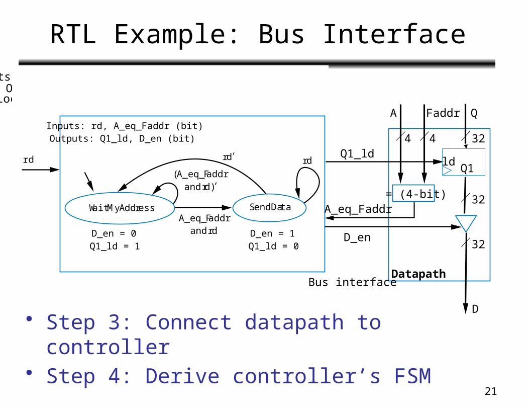
RTL Example: Bus Interface
• Step 3: Connect datapath to controller• Step 4: Derive controller’s FSM
WaitMyAddress
Inputs: rd (bit); Q (32 bits); A, Faddr (4 bits)Outputs: D (32 bits)Local register: Q1 (32 bits)
rd’ rd
SendData
D = “Z”Q1 = Q
(A = Faddr)and rd
((A = Faddr)and rd)’
D = Q1rd
Inputs: rd, A_eq_Faddr (bit)Outputs: Q1_ld, D_en (bit)
WaitMyAddress
rd‘ rd
SendData
D_en = 0Q1_ld = 1
D_en = 1Q1_ld = 0
A_eq_Faddrandrd
(A_eq_Faddrandrd)‘
DatapathBus interface
Q1_ldld
Q1
Faddr Q
4 4 32
A
D_en
A_eq_Faddr= (4-bit) 32
32
D

22
Readings
• Chapter 8– Sections 8.5, 8.6