Embed Size (px)
Citation preview
COXSWAINENGINEERING
Marine Engines -Basic Operation4 Stroke & 2 Stroke
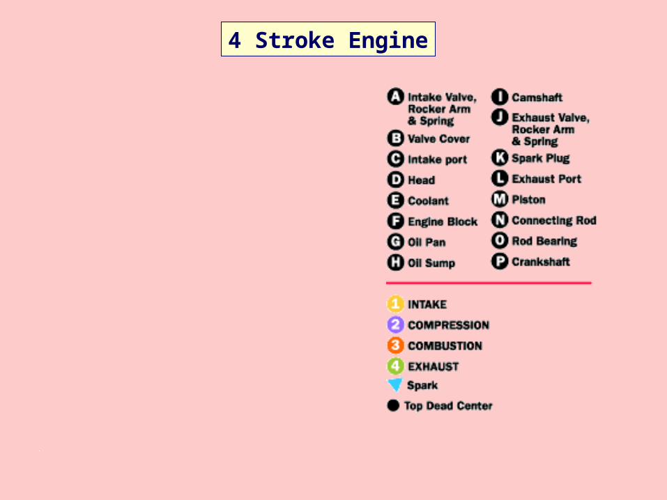
4 Stroke Engine
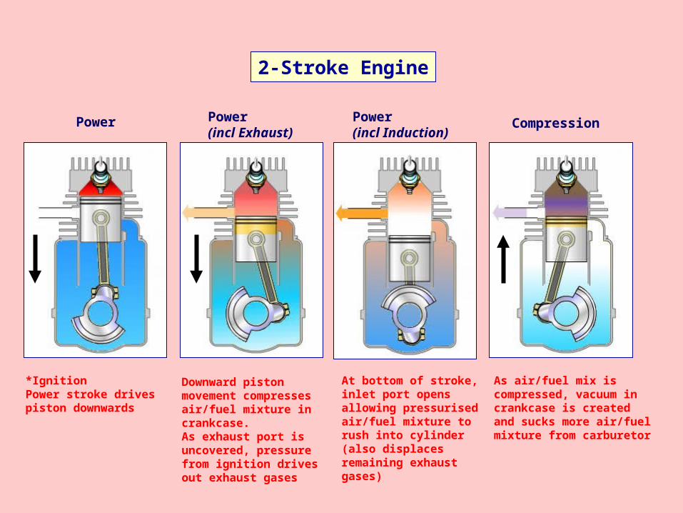
2-Stroke Engine
*IgnitionPower stroke drives piston downwards
Downward piston movement compresses air/fuel mixture in crankcase.As exhaust port is uncovered, pressure from ignition drives out exhaust gases
At bottom of stroke, inlet port opens allowing pressurised air/fuel mixture to rush into cylinder (also displaces remaining exhaust gases)
As air/fuel mix is compressed, vacuum in crankcase is created and sucks more air/fuel mixture from carburetor
Power Power(incl Exhaust)
Power(incl Induction)
Compression
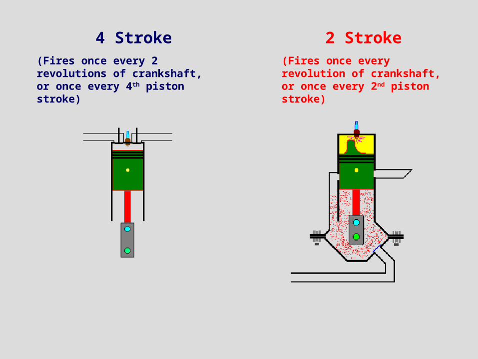
4 Stroke 2 Stroke(Fires once every 2 revolutions of crankshaft, or once every 4th piston stroke)
(Fires once every revolution of crankshaft, or once every 2nd piston stroke)
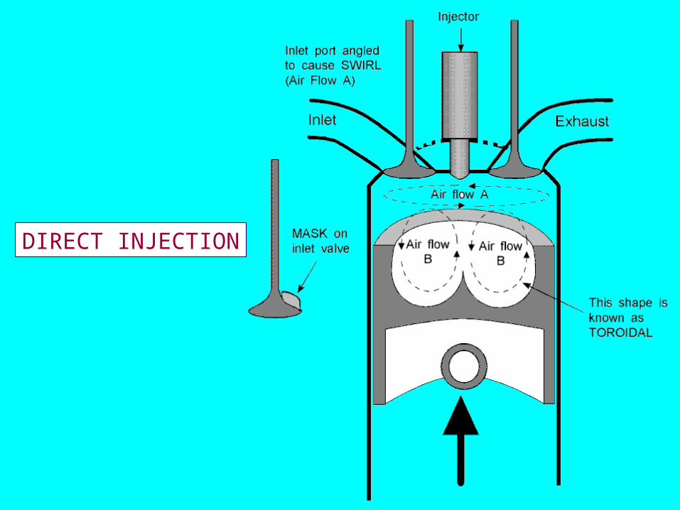
DIRECT INJECTION
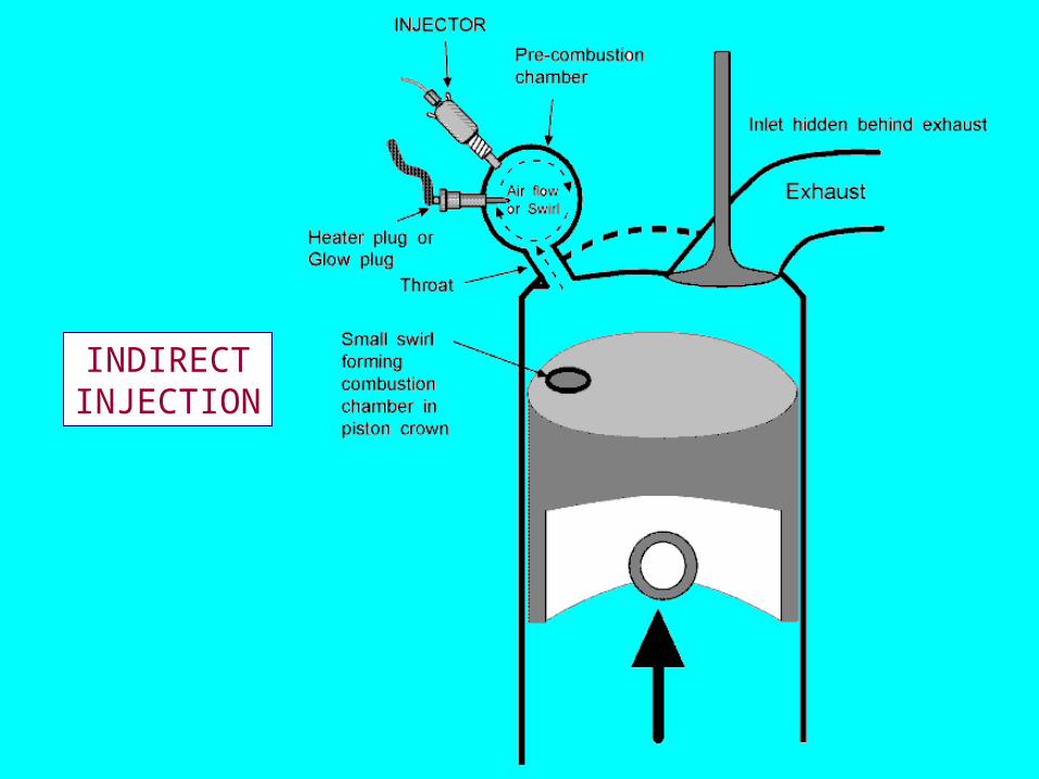
INDIRECTINJECTION
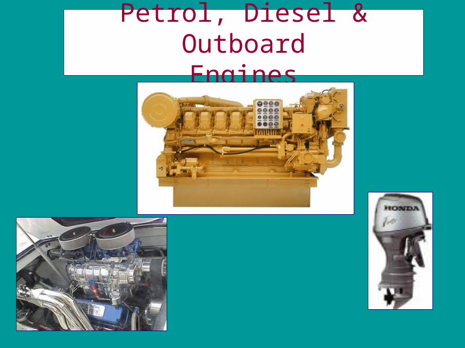
Petrol, Diesel & OutboardEngines
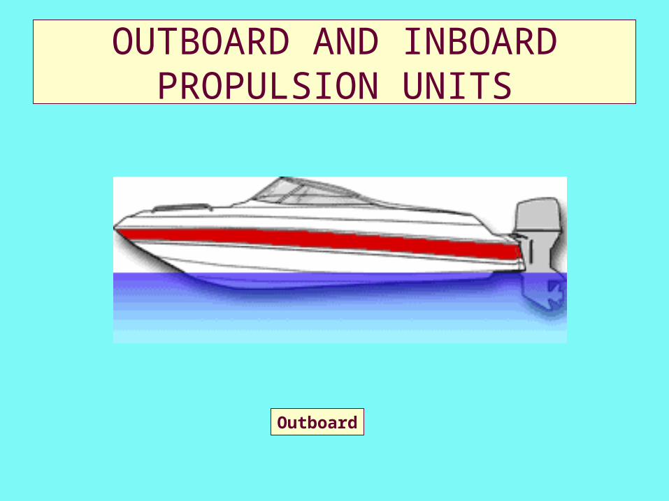
OUTBOARD AND INBOARD PROPULSION UNITS
Outboard
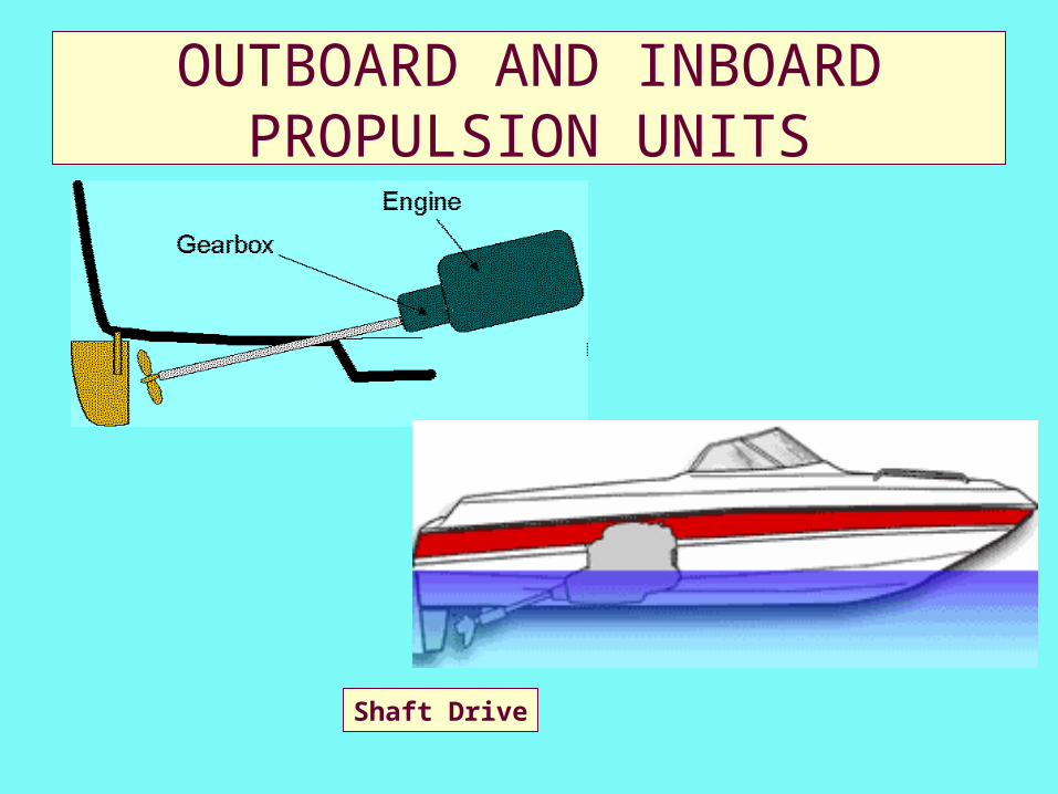
OUTBOARD AND INBOARD PROPULSION UNITS
Shaft Drive
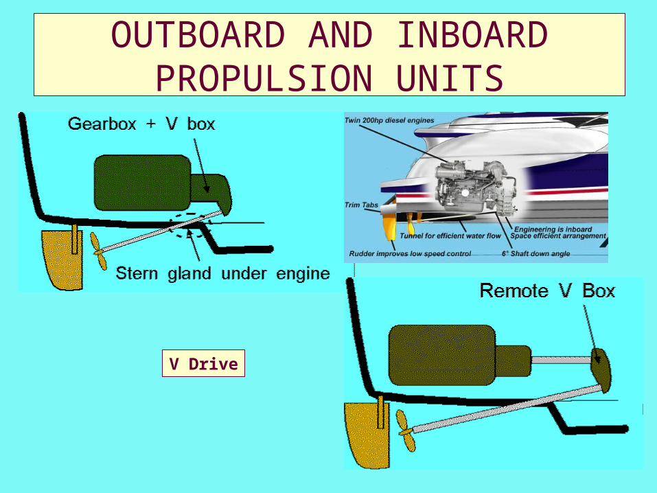
OUTBOARD AND INBOARD PROPULSION UNITS
V Drive
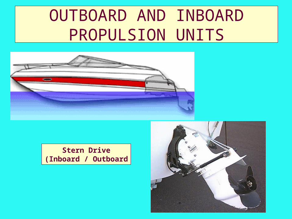
OUTBOARD AND INBOARD PROPULSION UNITS
Stern Drive(Inboard / Outboard
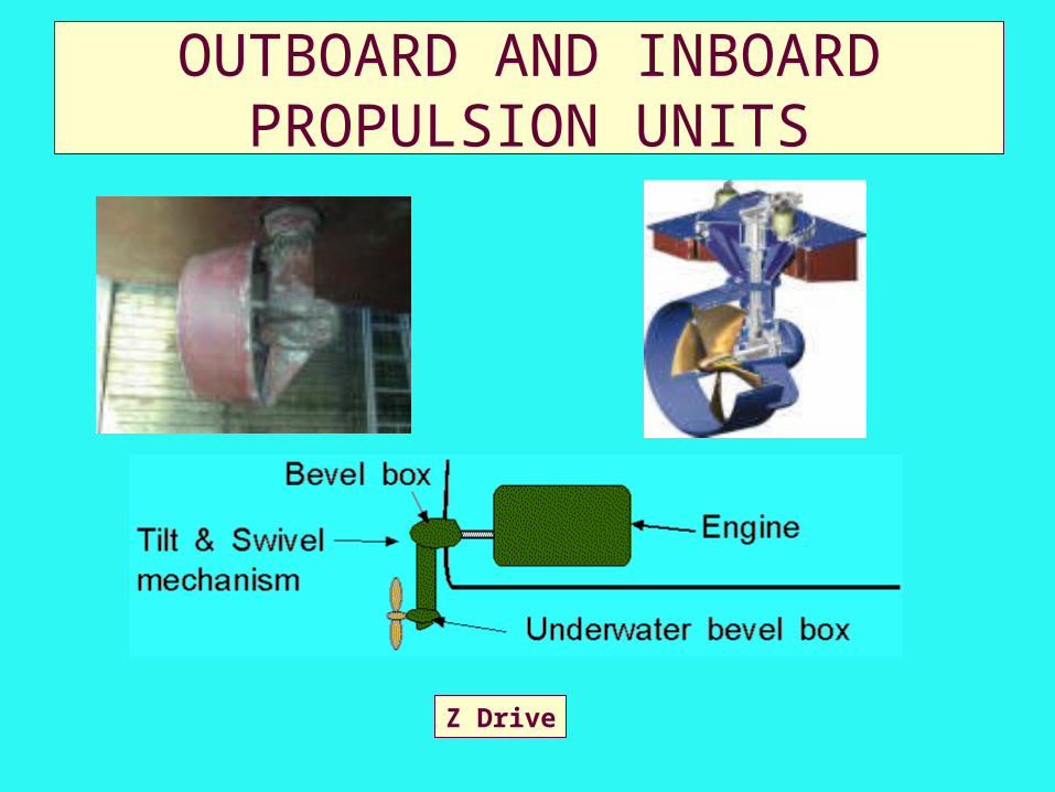
OUTBOARD AND INBOARD PROPULSION UNITS
Z Drive
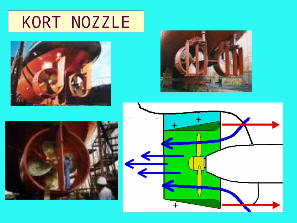
KORT NOZZLE
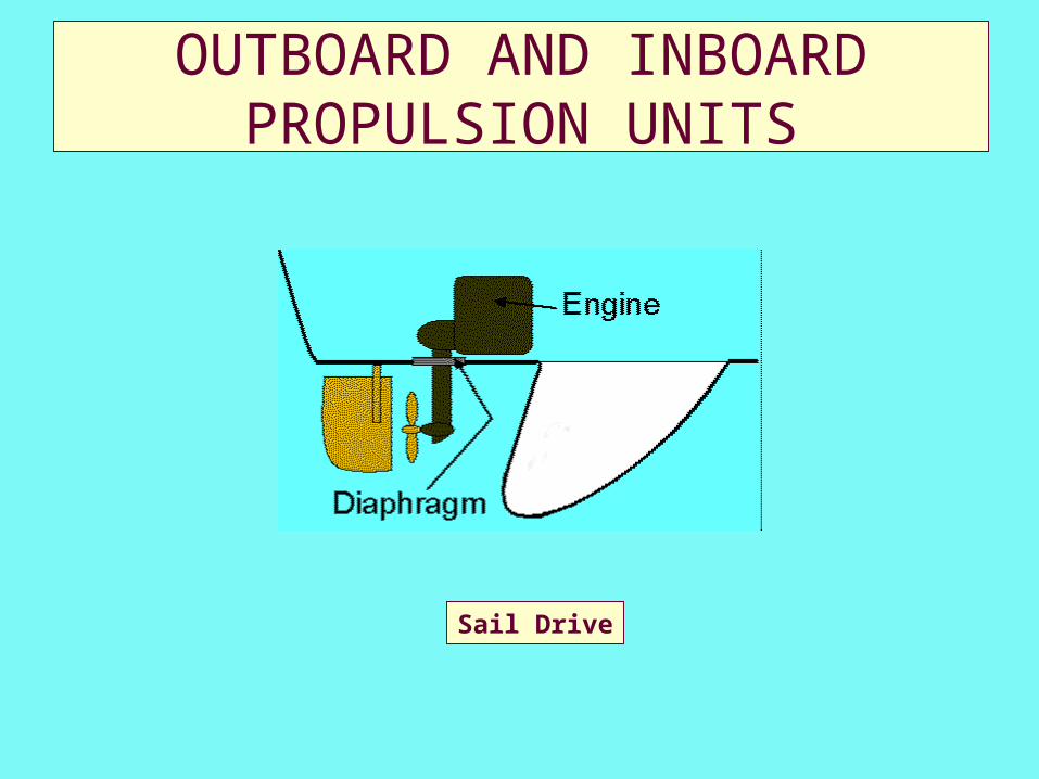
OUTBOARD AND INBOARD PROPULSION UNITS
Sail Drive
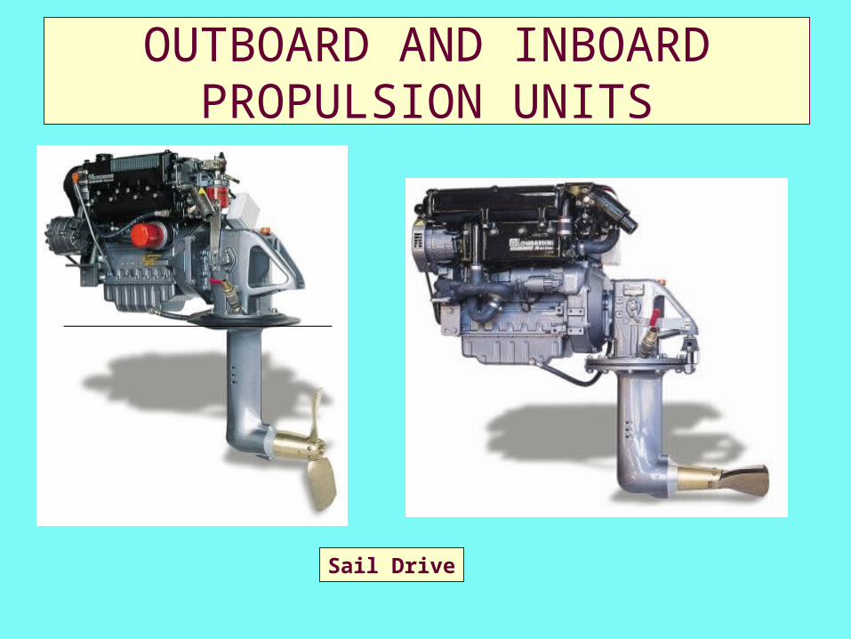
OUTBOARD AND INBOARD PROPULSION UNITS
Sail Drive
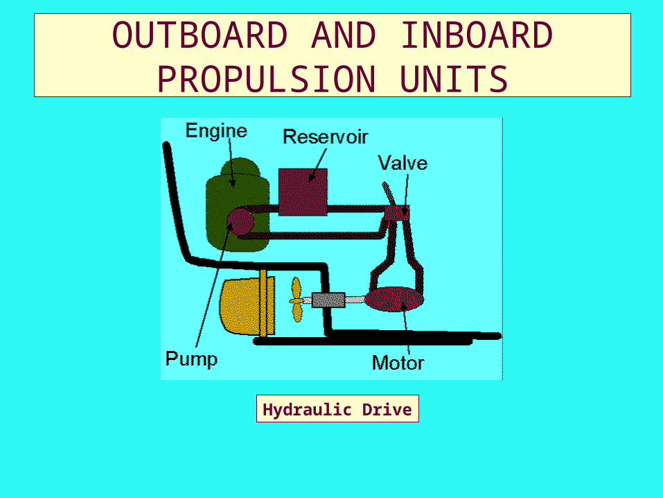
OUTBOARD AND INBOARD PROPULSION UNITS
Hydraulic Drive
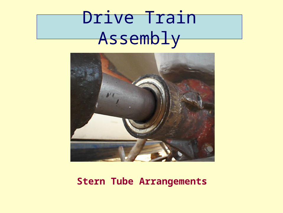
Drive Train Assembly
Stern Tube Arrangements
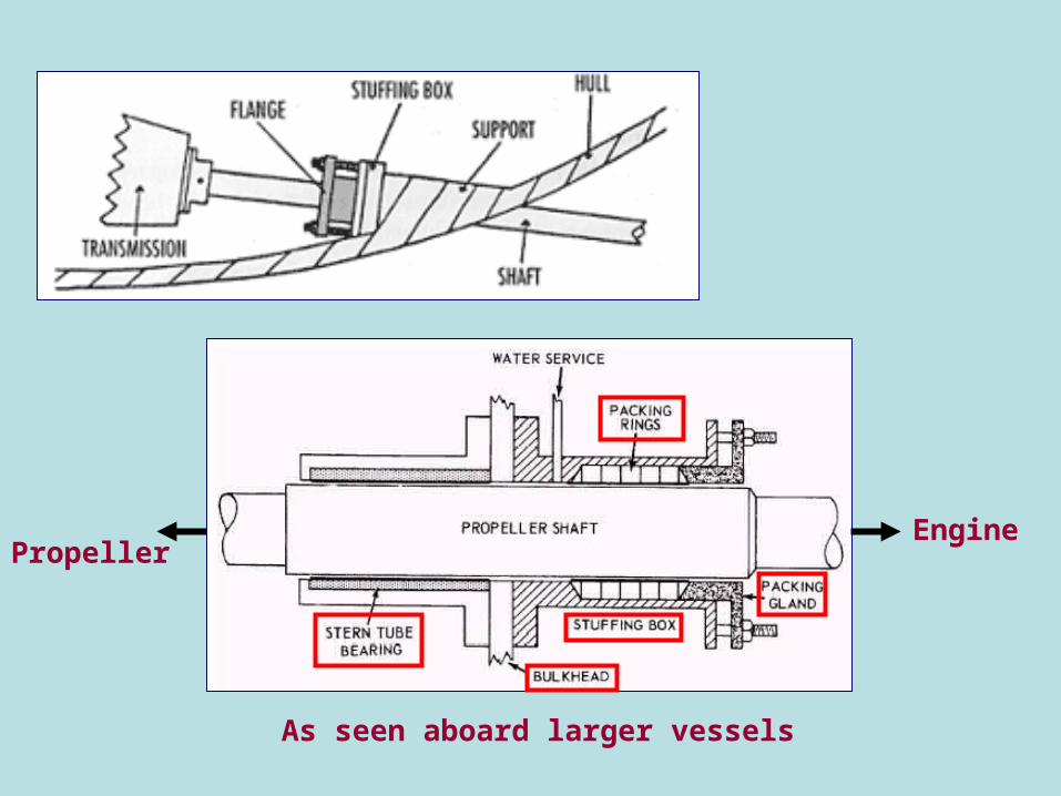
PropellerEngine
As seen aboard larger vessels
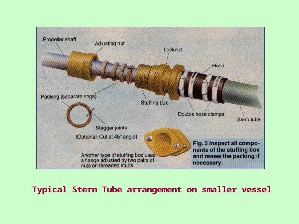
Typical Stern Tube arrangement on smaller vessel
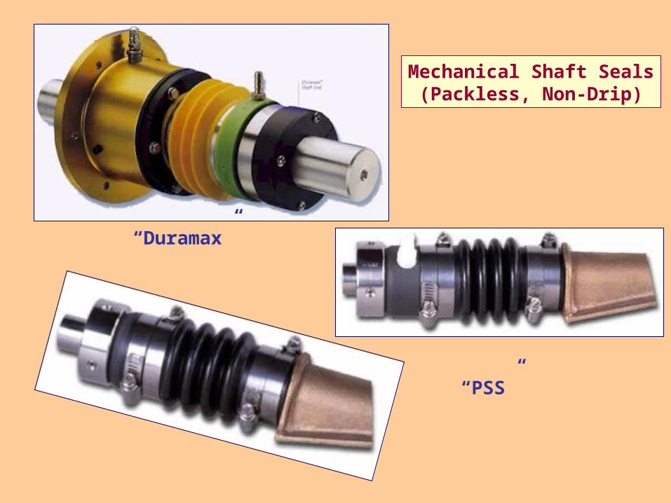
Mechanical Shaft Seals(Packless, Non-Drip)
“Duramax”
“PSS”
Steering Gear
• Wire and Pulley
• Push/Pull
• Chain and Steering Box
• Hydraulic
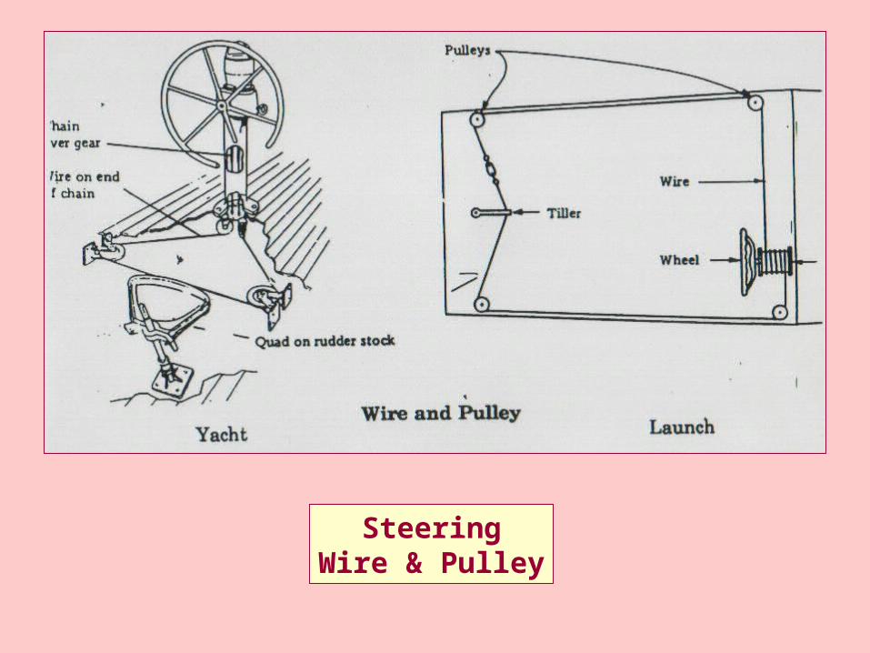
SteeringWire & Pulley
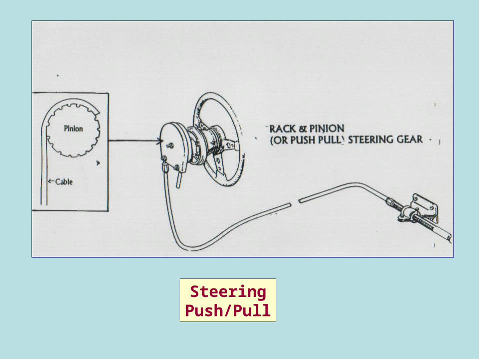
SteeringPush/Pull
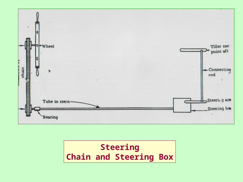
SteeringChain and Steering Box
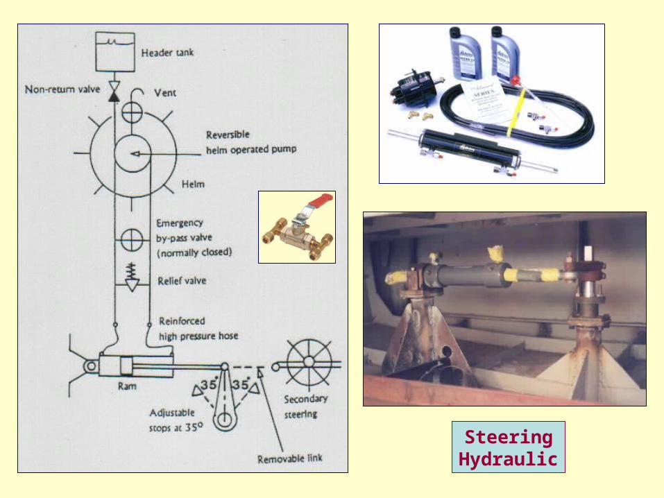
SteeringHydraulic
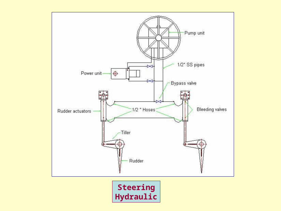
SteeringHydraulic
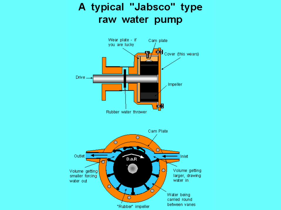
Cooling, Lubricating & Fuel Systems
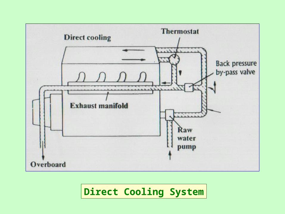
Direct Cooling System
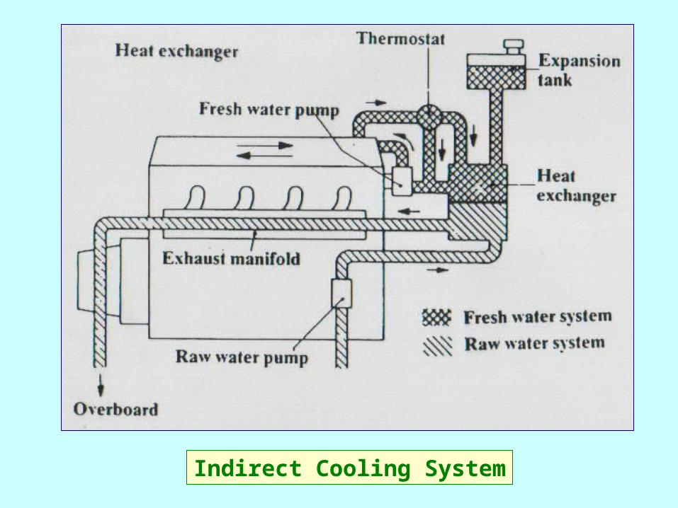
Indirect Cooling System
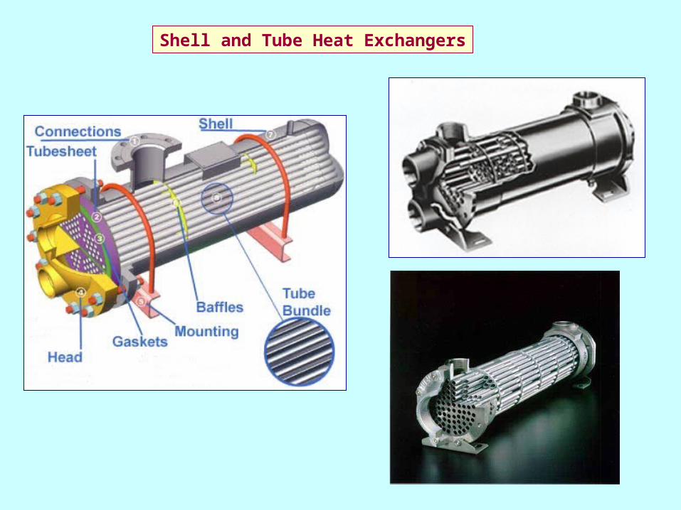
Shell and Tube Heat Exchangers
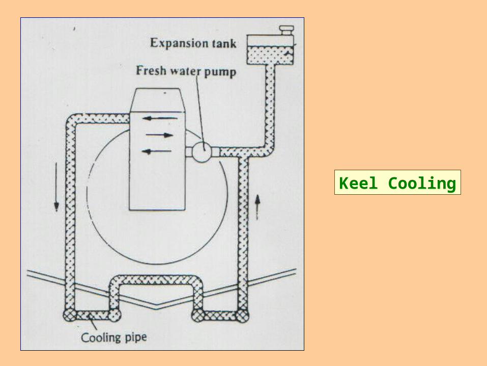
Keel Cooling
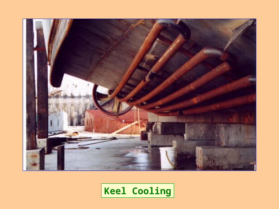
Keel Cooling
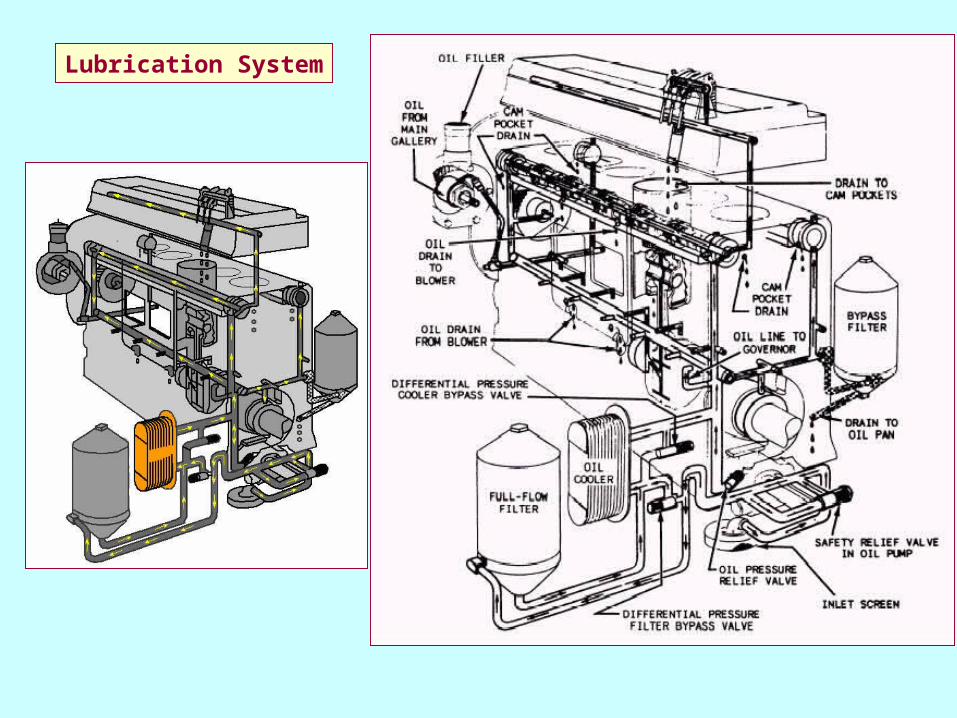
Lubrication System
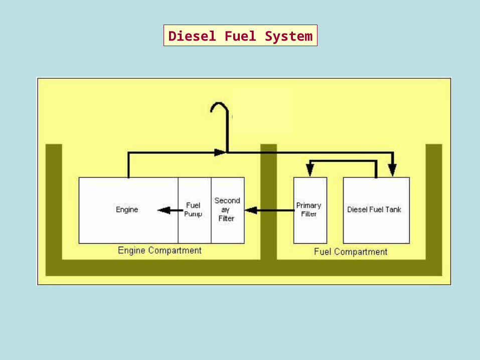
Diesel Fuel System
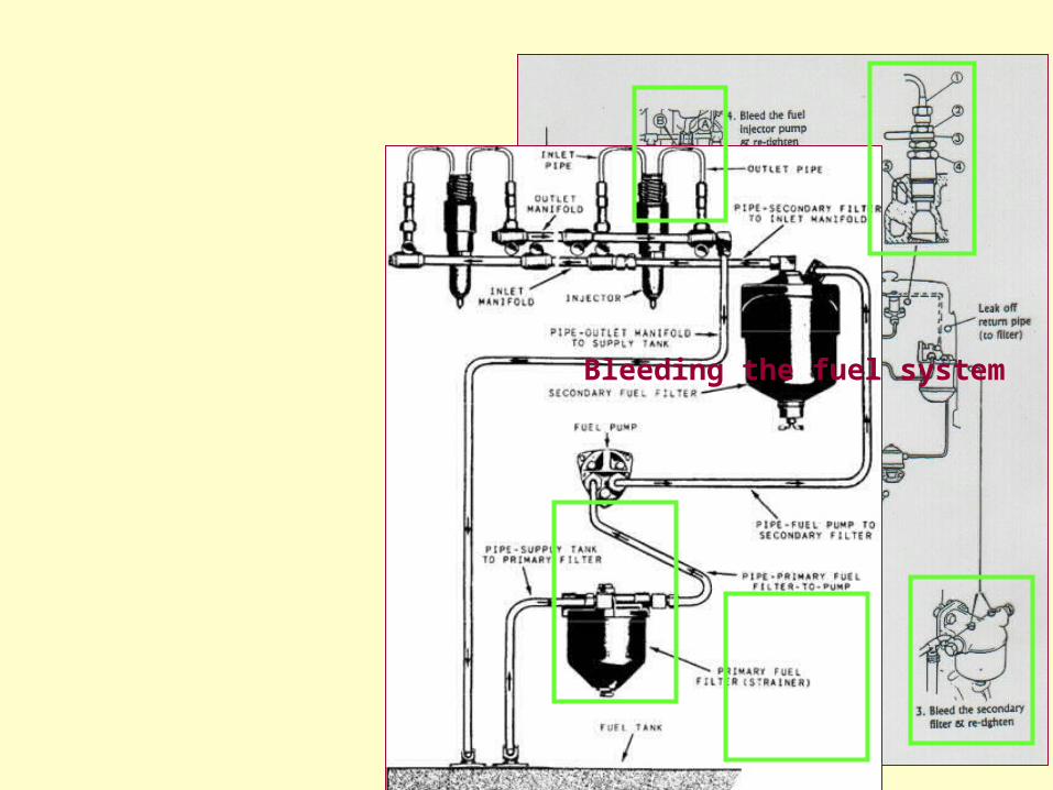
Bleeding the fuel system
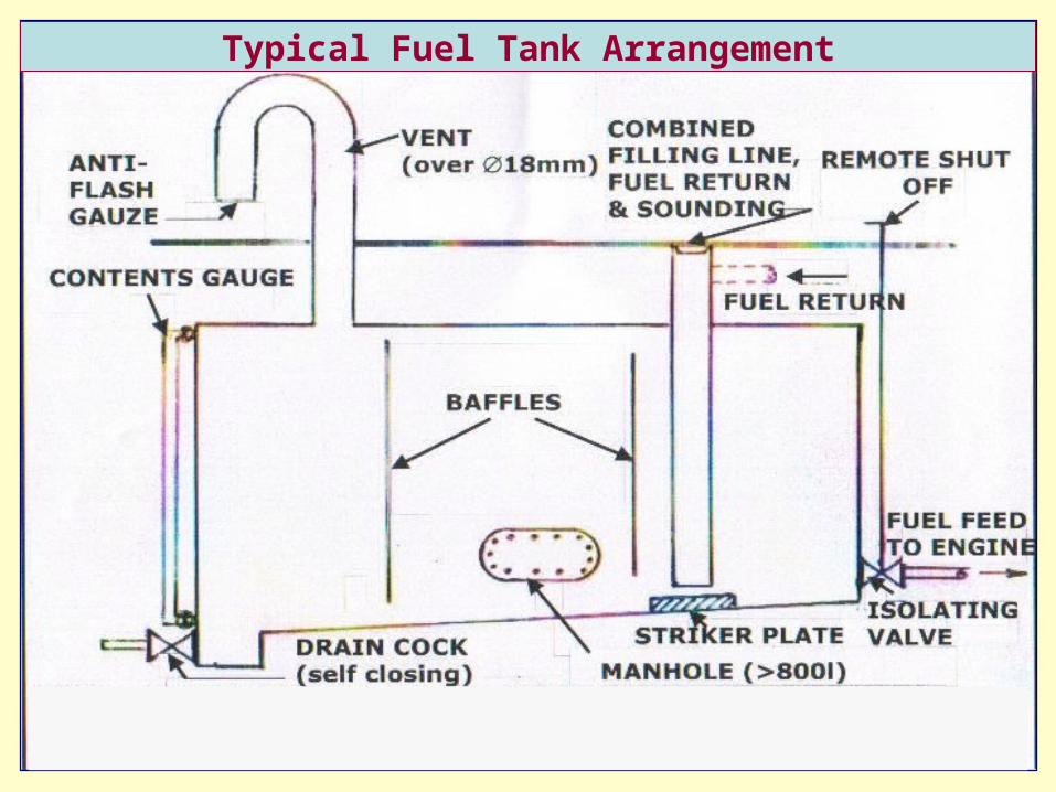
Typical Fuel Tank Arrangement
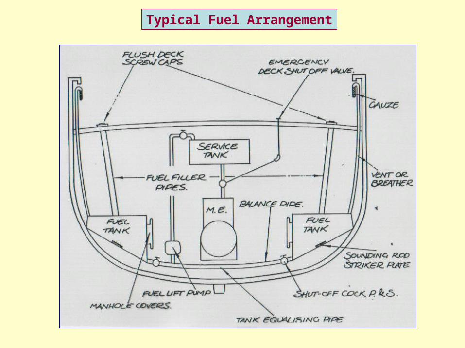
Typical Fuel Arrangement
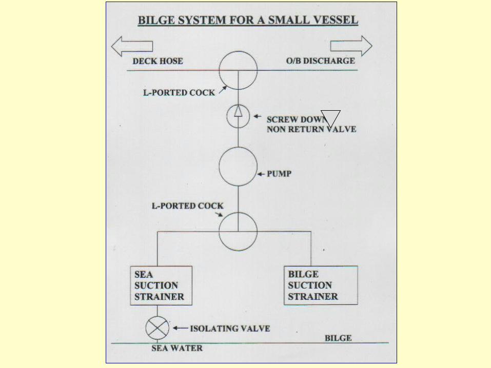
Bilge & Pumping Arrangements
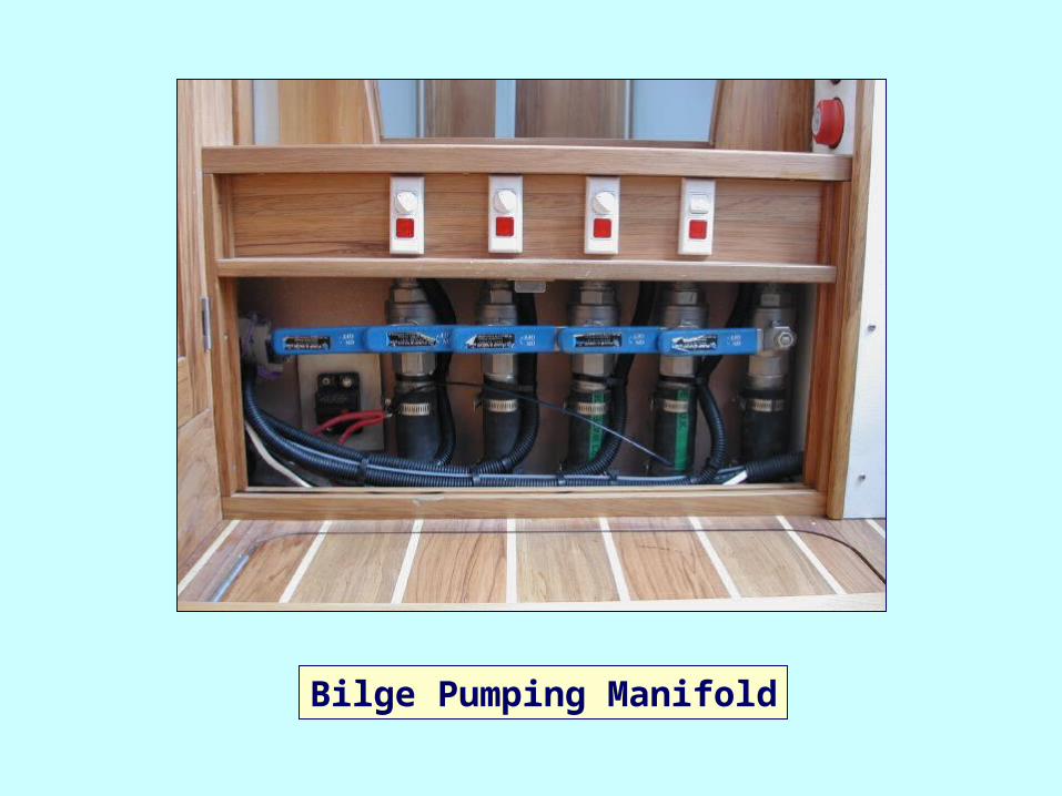
Bilge Pumping Manifold
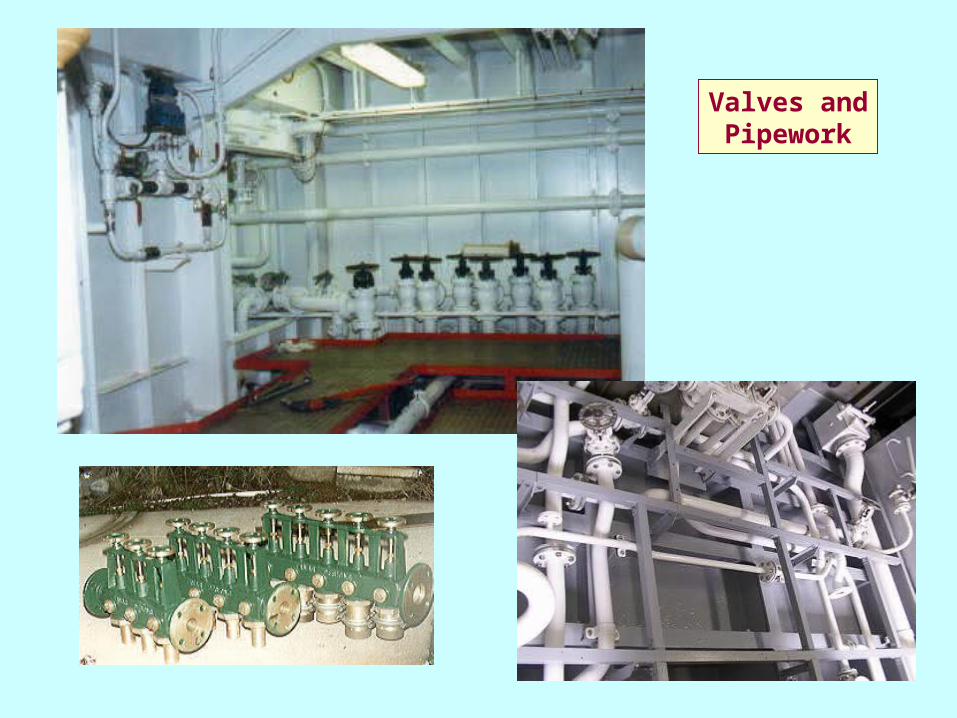
Valves andPipework
BACK FLOODING
Q. WHAT IS BACK FLOODING?
Ans. Water entering vessel through existing pipework
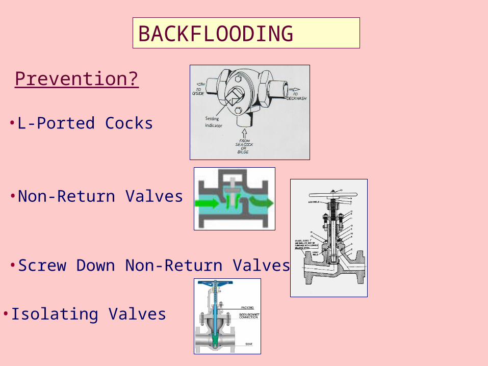
BACKFLOODING
Prevention?
•Screw Down Non-Return Valves
•L-Ported Cocks
•Non-Return Valves
•Isolating Valves
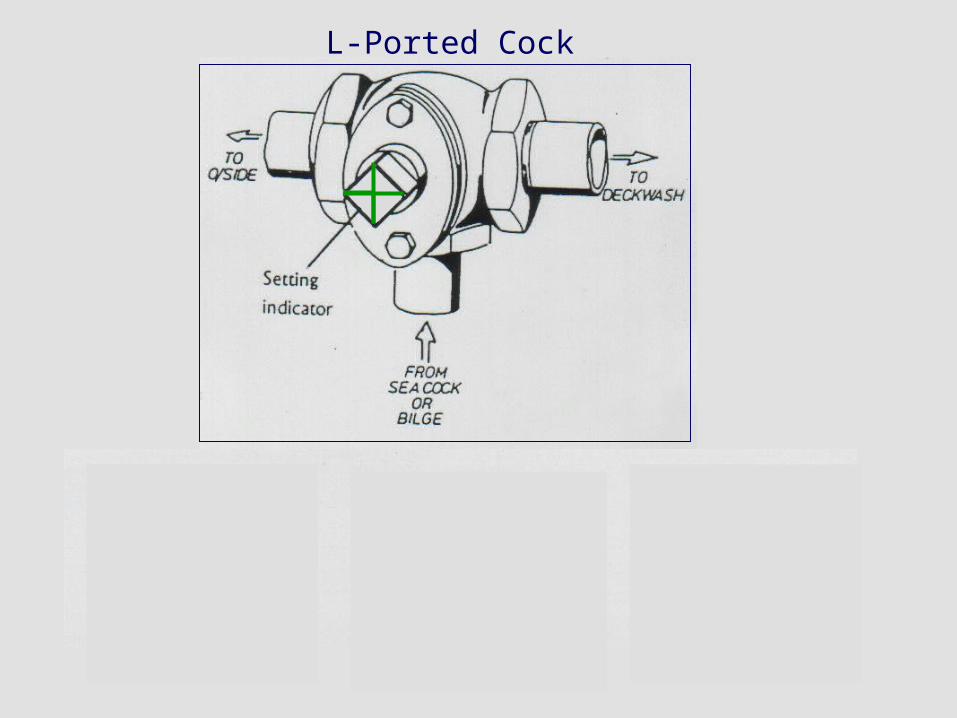
O/B D/Wash
Open – from Sea Cock to Deck Wash
O/B D/Wash
Open – from Sea Cock/Bilge to Overboard Discharge
O/B D/Wash
CLOSED
L-Ported Cock

Non-Return Valve
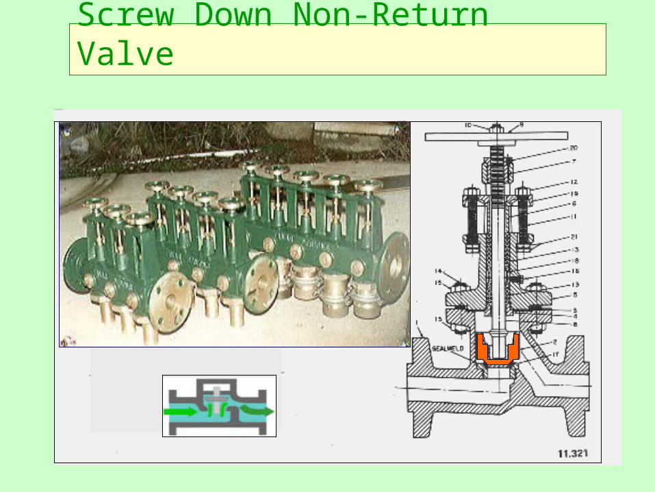
Screw Down Non-Return Valve
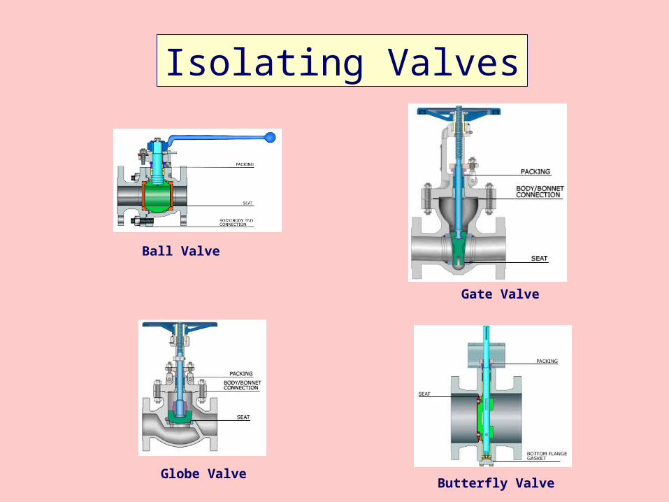
Isolating Valves
Ball Valve
Globe Valve
Gate Valve
Butterfly Valve

BILGE PUMPING
2. Select Seawater suction
3. Select Over Board discharge
4. Start pump and ensure seawater is being
pumped over board
5. Select Bilge suction - ensure bilge water
discharge over board
6. As soon as over board discharge flow lessens, select
Seawater suction and ensure water is being pumped over board
7. Shut down pump
1. Ensure Sea Water isolating valve is OPEN
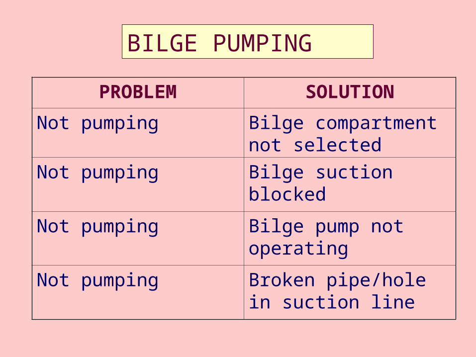
BILGE PUMPING
PROBLEM SOLUTION
Not pumping Bilge compartment not selected
Not pumping Bilge suction blocked
Not pumping Bilge pump not operating
Not pumping Broken pipe/hole in suction line
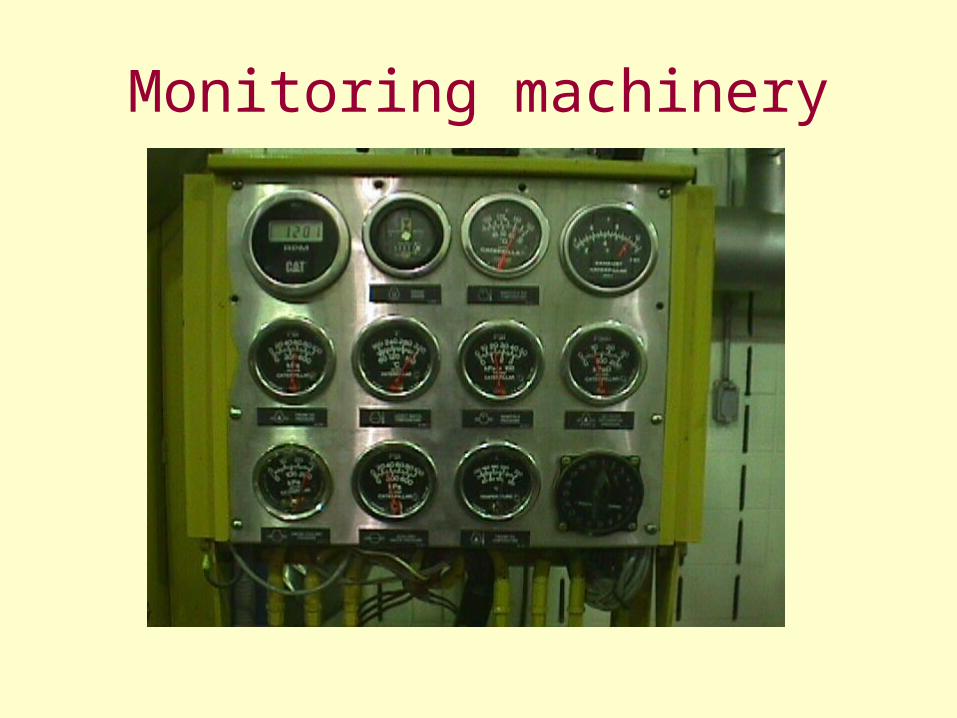
Monitoring machinery
Pre-start Checks
• Fuel – Sufficient amount for journey, Fuel cock on, Water drained from sedimenter
• Oil – At correct level, top up if necessary
• Water – At correct level, top up if necessary
• Batteries – Electrolyte level OK, Correct Battery Bank selected
• Drive belts, Hoses in good condition & adjusted correctly
• Sea Water Cock open (strainer clean)
• Bilge pump valves set correctly
Operating Checks• Engine gauges (Coolant Temperature, Oil Pressure,
Oil Temperature, Exhaust Temperature, Gearbox Oil Pressure, Gearbox Oil Temperature……..)
• Visual checks for oil/water leaks, unusual vibration
• Pumps operational (o/board cooling discharge, wet exhaust discharge)
• Genset charging
• Sterntube not overheating/leaking excessively
• Colour of exhaust gases not abnormal– Black smoke = injector problems– Blue smoke = faulty piston rings– White smoke = poor compression
Checks on Shut-down
• Let engine idle for some time to cool down (especially if turbocharged)
• Shut down as per manufacturer’s instructions
• Turn off Fuel cock
• Turn off Sea Water Suction
• Turn off Battery Master Switch
• Check bilge pump is off and ensure no backflooding
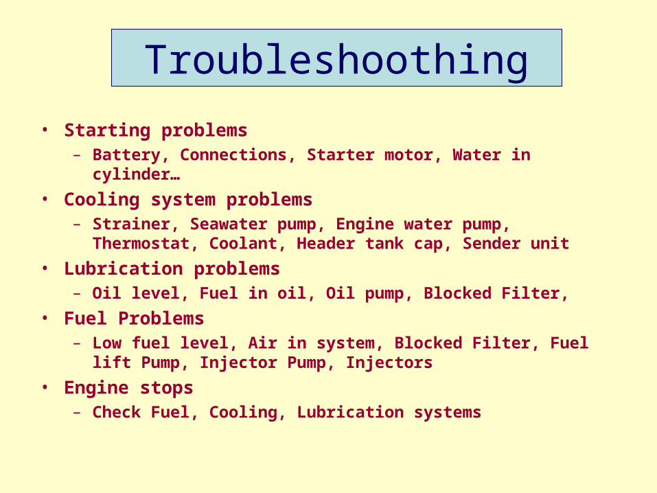
Troubleshoothing
• Starting problems– Battery, Connections, Starter motor, Water in cylinder…
• Cooling system problems– Strainer, Seawater pump, Engine water pump,
Thermostat, Coolant, Header tank cap, Sender unit
• Lubrication problems– Oil level, Fuel in oil, Oil pump, Blocked Filter,
• Fuel Problems– Low fuel level, Air in system, Blocked Filter, Fuel lift
Pump, Injector Pump, Injectors
• Engine stops– Check Fuel, Cooling, Lubrication systems
Electrical Systems
Direct Current (DC)&
Alternating Current (AC)
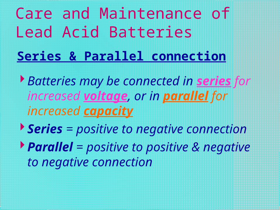
Care and Maintenance of Lead Acid Batteries
Series & Parallel connection
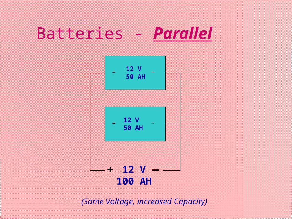
Batteries may be connected in series for increased voltage, or in parallel for increased capacity
Series = positive to negative connection
Parallel = positive to positive & negative to negative connection
+ _+ _
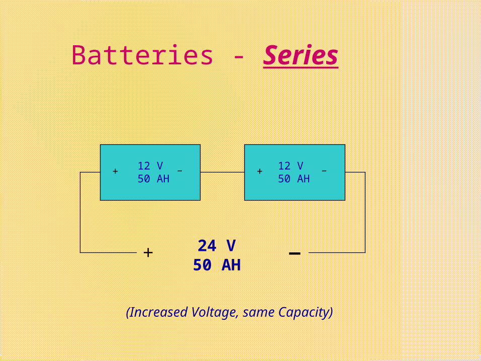
Batteries - Series
+ _
12 V50 AH
12 V50 AH
24 V50 AH
(Increased Voltage, same Capacity)
+ _
+ _
Batteries - Parallel
12 V50 AH
12 V50 AH
+ _12 V100 AH
(Same Voltage, increased Capacity)
Care and Maintenance of Lead Acid Batteries
For best performance:
Keep Battery clean, dry and free from terminal corrosion
Electrolyte at correct level
Correctly charged
Battery Cleanliness
A dirty battery or spilt electrolyte may provide a path for electrical current to leak away
Corrosion on battery terminals (green-white powder) may seriously affect or prevent battery from supplying current
Electrolyte Level
Keep topped up with Distilled or Demineralised water only
(Chemical action inside battery causes water loss)
Maintain water level at approximately 10mm above plates inside battery
Correct Charging
To provide the best service, a battery must be correctly charged
Both overcharging and undercharging can seriously affect a battery’s performance
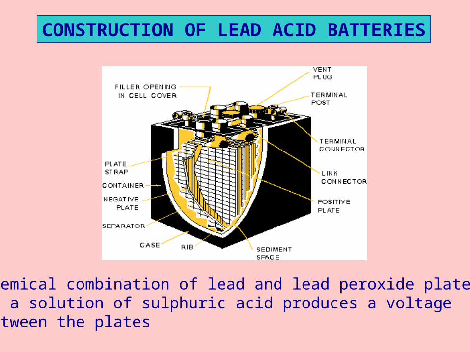
CONSTRUCTION OF LEAD ACID BATTERIES
Chemical combination of lead and lead peroxide plates,in a solution of sulphuric acid produces a voltage between the plates
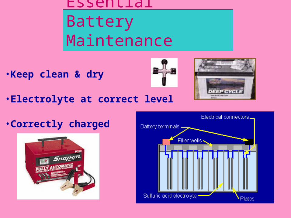
Essential Battery Maintenance
•Keep clean & dry
•Electrolyte at correct level
•Correctly charged
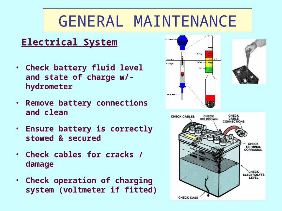
GENERAL MAINTENANCE
• Check battery fluid level and state of charge w/- hydrometer
• Remove battery connections and clean
• Ensure battery is correctly stowed & secured
• Check cables for cracks / damage
• Check operation of charging system (voltmeter if fitted)
Electrical System
Care and Maintenance of Lead Acid Batteries
Battery condition may be determined by:
Measuring the Specific Gravity
Measuring On-Load Terminal Voltage
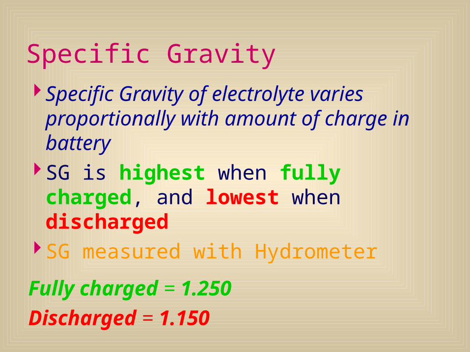
Specific Gravity Specific Gravity of electrolyte varies
proportionally with amount of charge in battery
SG is highest when fully charged, and lowest when discharged
SG measured with Hydrometer
Fully charged = 1.250Discharged = 1.150
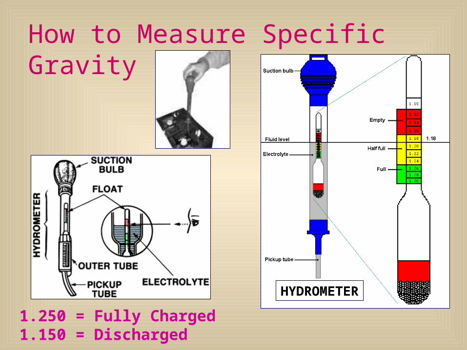
How to Measure Specific Gravity
1.250 = Fully Charged1.150 = Discharged
HYDROMETER
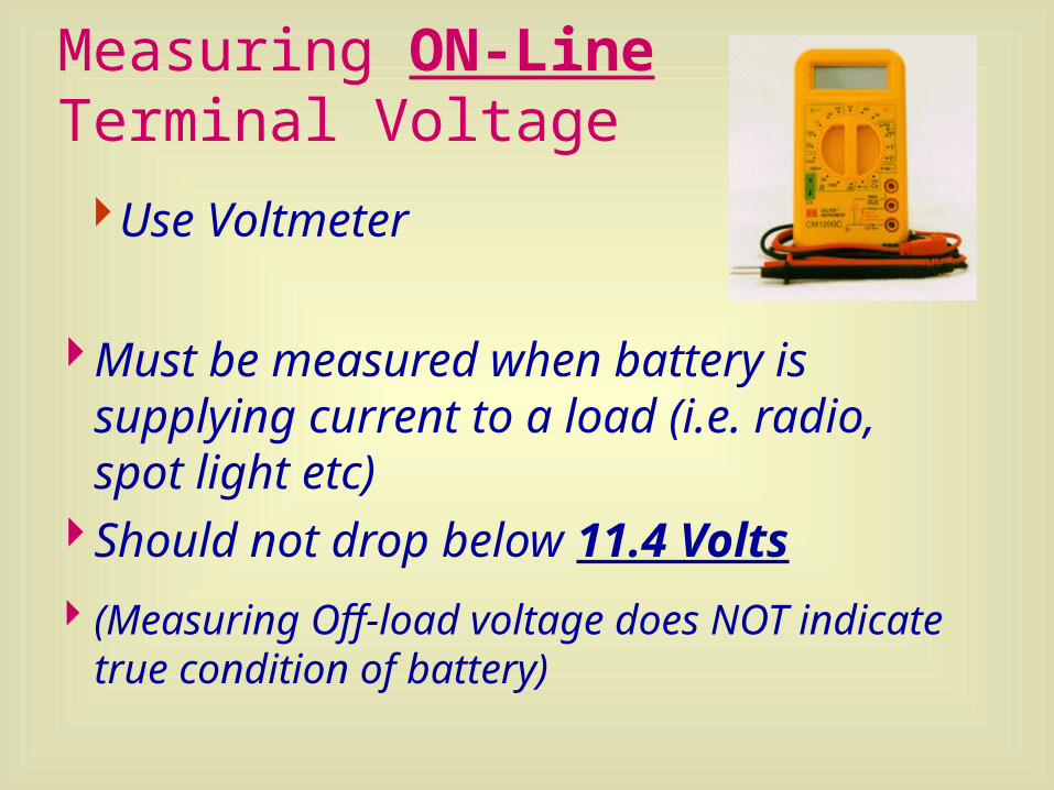
Measuring ON-Line Terminal Voltage
Must be measured when battery is supplying current to a load (i.e. radio, spot light etc)
Should not drop below 11.4 Volts
(Measuring Off-load voltage does NOT indicate true condition of battery)
Use Voltmeter
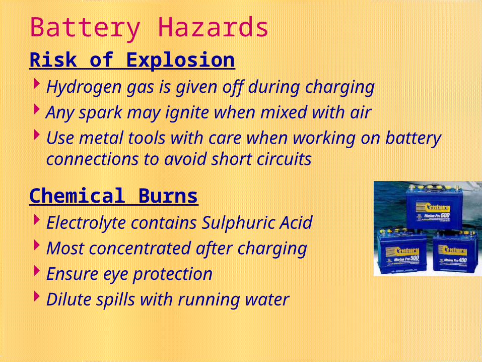
Battery HazardsRisk of Explosion Hydrogen gas is given off during charging Any spark may ignite when mixed with air Use metal tools with care when working on
battery connections to avoid short circuits
Chemical Burns Electrolyte contains Sulphuric Acid Most concentrated after charging Ensure eye protection Dilute spills with running water
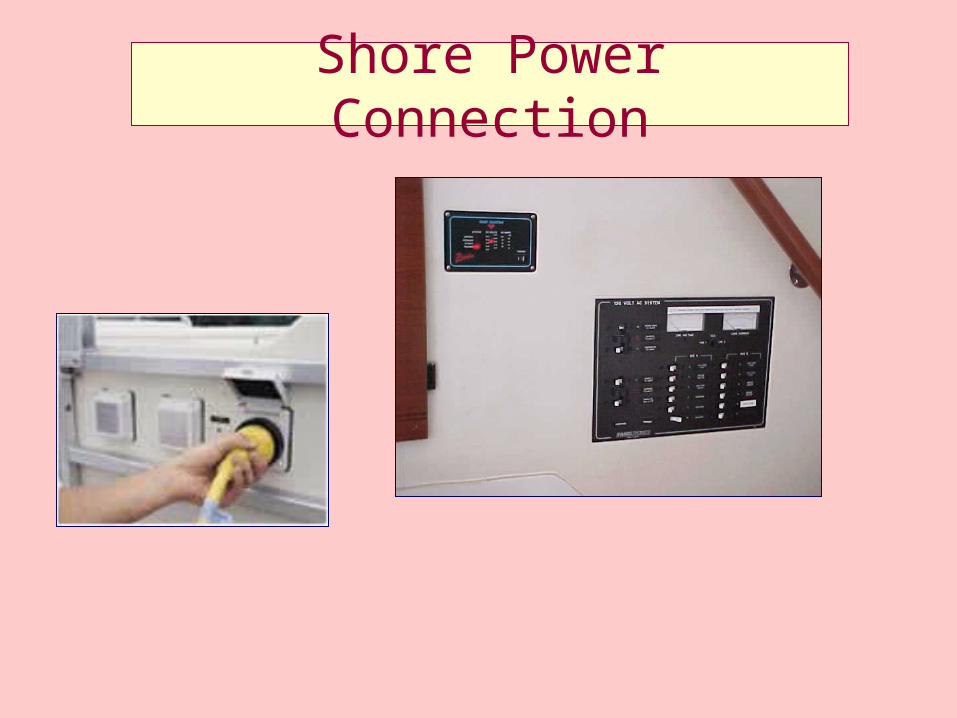
Shore Power Connection
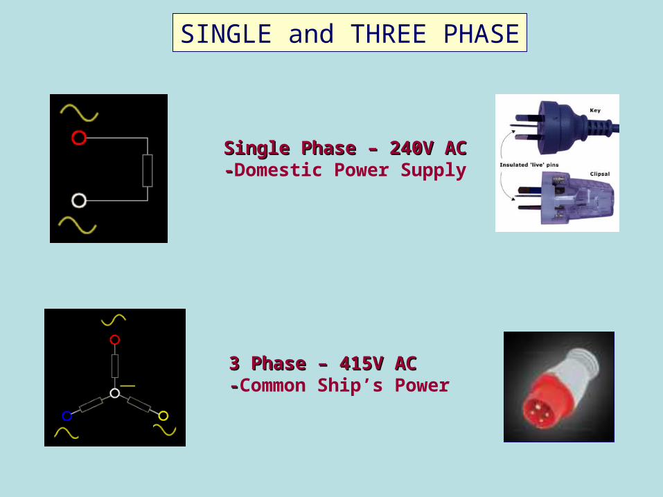
3 Phase – 415V AC3 Phase – 415V AC--Common Ship’s Power
Single Phase – 240V ACSingle Phase – 240V AC--Domestic Power Supply
SINGLE and THREE PHASE
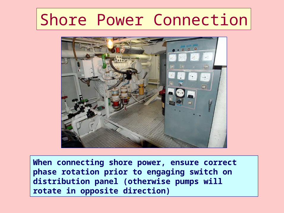
Shore Power Connection
When connecting shore power, ensure correct phase rotation prior to engaging switch on distribution panel (otherwise pumps will rotate in opposite direction)
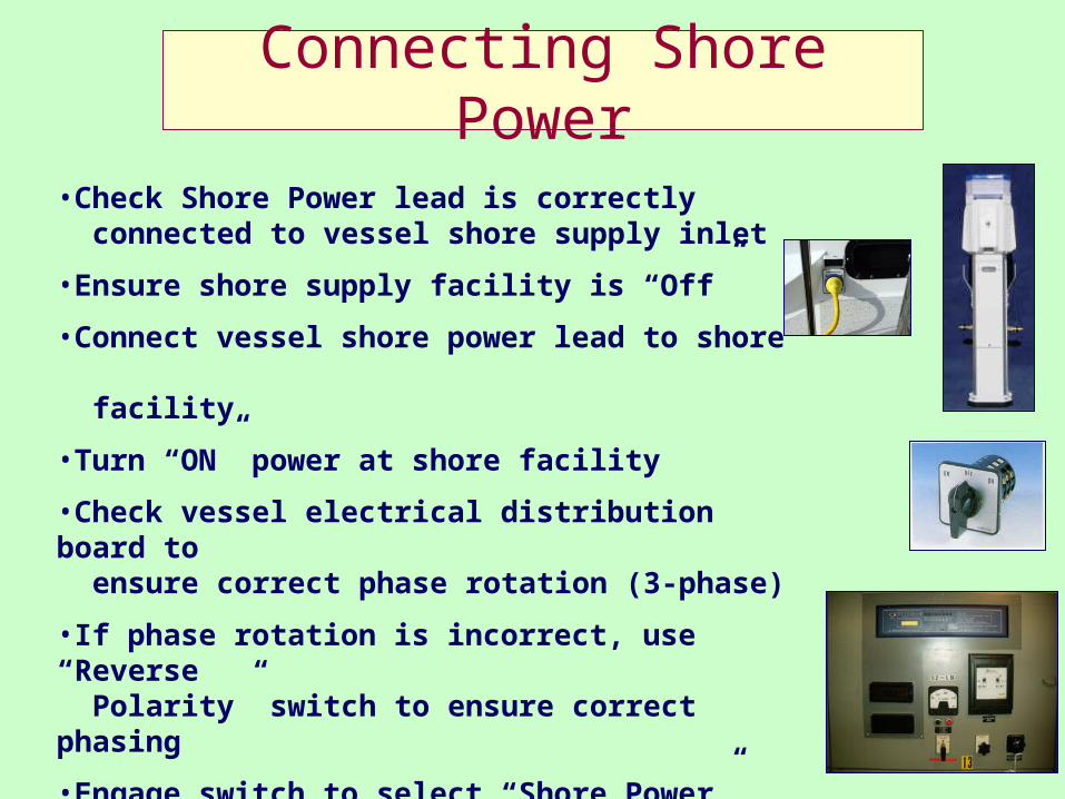
Connecting Shore Power
•Check Shore Power lead is correctly connected to vessel shore supply inlet
•Ensure shore supply facility is “Off”
•Connect vessel shore power lead to shore
facility
•Turn “ON” power at shore facility
•Check vessel electrical distribution board to ensure correct phase rotation (3-phase)
•If phase rotation is incorrect, use “Reverse Polarity” switch to ensure correct phasing
•Engage switch to select “Shore Power”
•Shut down ship supply genset
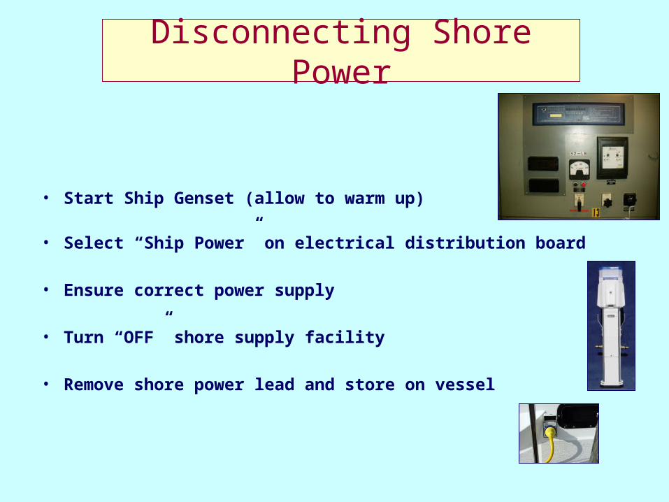
Disconnecting Shore Power
• Start Ship Genset (allow to warm up)
• Select “Ship Power” on electrical distribution board
• Ensure correct power supply
• Turn “OFF” shore supply facility
• Remove shore power lead and store on vessel
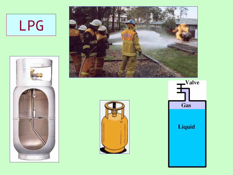
LPG
LPG
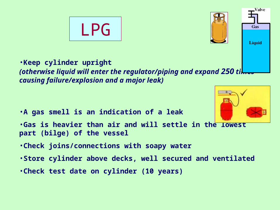
•Keep cylinder upright (otherwise liquid will enter the regulator/piping and expand 250 times causing failure/explosion and a major leak)
•A gas smell is an indication of a leak
•Gas is heavier than air and will settle in the lowest part (bilge) of the vessel
•Check joins/connections with soapy water
•Store cylinder above decks, well secured and ventilated
•Check test date on cylinder (10 years)
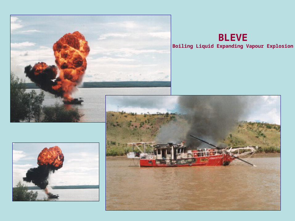
BLEVEBoiling Liquid Expanding Vapour Explosion

END COXSWAIN
ENGINEERING