Embed Size (px)
Citation preview

Two-Way, Three-Way and Four-Way Solenoid Valves
Catalog CFL00897
Skinner Valve
Cover.qxp 6/6/2007 4:34 PM Page 1 (3,1)
Courtesy of Steven Engineering, Inc.-230 Ryan Way, South San Francisco, CA 94080-6370-Main Office: (650) 588-9200-Outside Local Area: (800) 258-9200-www.stevenengineering.com

Skinner ValveIntroduction
Fluid Control Division
Skinner has been recognized as a leader in solenoid valve technology since 1949when they first started manufacturingsolenoid valves.
The Skinner and Lucifer facilities areboth vertically integrated, manufacturing alarge percentage of their component partscomplete from the raw material level. Thispermits a high degree of control over thequality and availability of products. Eachfacility is equipped with a complete staff ofexperienced design engineers permittingrapid completion of customized valve designsfor specific user requirements. Also, eachfacility has well equipped evaluation andtesting laboratories to ensure proper valveoperation, long cycle life, and optimumreliability of the product in the application.
With many affiliates worldwide, anextensive distribution network, and broadproduct breadth, Parker is in a uniqueposition to service the world’s requirementsfor solenoid valves.
Table of Contents
Product Overview ........................................................................ 1
Condensed Valve Listing .......................................................... 2-8
Valve Ordering Information .................................................... 9-117000 Series Ordering ........................................................ 93000 Series Ordering ...................................................... 10A, B, C, MB and V9 Ordering .......................................... 10Intrinsically Safe Ordering................................................ 117000 Series Coil Information...................................... 12-133000 Series Coil Information .......................................... 13
Skinner Two-Way Valve Specifications................................ 15-48Skinner 7000 Series Valves........................................ 15-40
General Purpose Valves .................................... 15-27Hot Water and Steam Valves.............................. 28-32High Pressure Valves ........................................ 33-35Anti-Water Hammer Valves ................................ 36-37Manual Reset Valves .............................................. 38Remote Pressure Valves.......................................... 39
Skinner 3000 Series Valves ........................................ 40-41Skinner B-Series Valves .................................................. 42Skinner C-Series Valves .................................................. 43Skinner LB27 Zero Delta P Valves.................................... 44
Skinner Three-Way Valve Specifications ............................ 46-72Skinner 7000 Series Valves ........................................ 46-63
General Purpose Valves .................................... 46-57Quick Exhaust Valves .............................................. 58High Pressure Valves ........................................ 59-60Manual Reset Valves .......................................... 61-62Remote Pressure Valves.......................................... 63
Skinner 3000 Series Valves ........................................ 64-66Skinner B-Series Valves.............................................. 67-68Skinner C-Series Valves.............................................. 69-70Skinner A-Series Valves.............................................. 71-72
Skinner Four-Way Valve Specifications .............................. 74-84Skinner 7000 Series Valves ........................................ 74-80
Direct Acting Valves .......................................... 74-75Pilot Operated Valves ........................................ 76-80
Skinner V-9 Series Valves .......................................... 81-84
Skinner Specialty Valve Specifications .............................. 86-90Skinner 7000 Series Valves.............................................. 86
Hydraulic Two-Way Valves ...................................... 86Dry Operator Valves .......................................... 87-89Hydraulic Three-Way Valves .................................... 90
Skinner Dual-Flow Valves ................................................ 91Skinner BP Proportional Valves.................................. 92-93Skinner Intrinsically Safe Valves .............................. 94-107
Intrinsically Safe Two-Way Valves...................... 95-96Intrinsically Safe Three-Way Valves .................. 97-98Intrinsically Safe Special Purpose Valves ................ 99Intrinsically Safe Four-Way Valves ................ 100-101Coil and Enclosure Information...................... 102-107
Skinner A-10 Series Valves .................................... 108-109Skinner MB Series Valves ...................................... 110-111Electropneumatic Pressure Regulator (EPP3) ........ 112-113
Technical Information ...................................................... 114-128Fluid Compatibility ................................................. 116-1177000 Series Numbering System ............................ 119-1207000 Series Electrical Options ....................................... 1213000 Series Numbering System .................................... 126Opportunity Data Sheet ................................................. 128
Terms and Conditions of Sale ................................................. 129
WARNINGFAILURE OR IMPROPER SELECTION OR IMPROPER USE OF THEPRODUCTS AND/OR SYSTEMS DESCRIBED HEREIN OR RELATEDITEMS CAN CAUSE DEATH, PERSONAL INJURY AND PROPERTYDAMAGE.
This document and other information from Parker Hannifin Corporation, itssubsidiaries and authorized distributors provide product and/or system optionsfor further investigation by users having technical expertise. It is importantthat you analyze all aspects of your application and review the informationconcerning the product or system in the current product catalog. Due to thevariety of operating conditions and applications for these products orsystems, the user, through its own analysis and testing, is solely responsiblefor making the final selection of the products and systems and assuring thatall performance, safety and warning requirements of the application are met.
The product described herein, including without limitation, product features,specifications, designs, availability and pricing, are subject to change byParker Hannifin Corporation and its subsidiaries at any time without notice.
Offer of SaleThe items described in this document are hereby offered for sale by ParkerHannifin Corporation, its subsidiaries or its authorized distributors. This offerand its acceptance are governed by the provisions stated on the separate pageof this document entitled “Terms and Conditions of Sale”. (See page 129.)
© Copyright 1997, Parker Hannifin Corporation. All rights reserved.
Courtesy of Steven Engineering, Inc.-230 Ryan Way, South San Francisco, CA 94080-6370-Main Office: (650) 588-9200-Outside Local Area: (800) 258-9200-www.stevenengineering.com
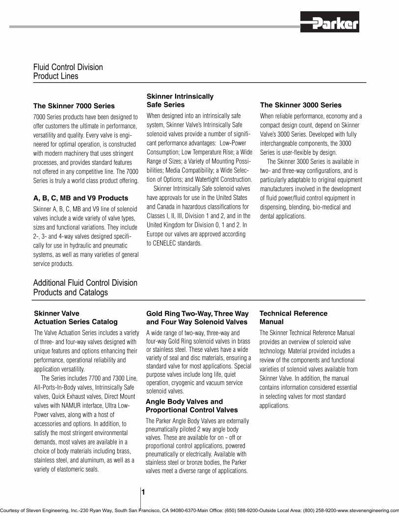
Fluid Control DivisionProduct Lines
The Skinner 7000 Series
7000 Series products have been designed tooffer customers the ultimate in performance,versatility and quality. Every valve is engi-neered for optimal operation, is constructedwith modern machinery that uses stringentprocesses, and provides standard featuresnot offered in any competitive line. The 7000Series is truly a world class product offering.
Skinner Intrinsically Safe Series
When designed into an intrinsically safesystem, Skinner Valve’s Intrinsically Safesolenoid valves provide a number of signifi-cant performance advantages: Low-PowerConsumption; Low Temperature Rise; a WideRange of Sizes; a Variety of Mounting Possi-bilities; Media Compatibility; a Wide Selec-tion of Options; and Watertight Construction.
Skinner Intrinsically Safe solenoid valveshave approvals for use in the United Statesand Canada in hazardous classifications forClasses I, II, III, Division 1 and 2, and in theUnited Kingdom for Division 0, 1 and 2. InEurope our valves are approved according to CENELEC standards.
1
The Skinner 3000 Series
When reliable performance, economy and acompact design count, depend on SkinnerValve’s 3000 Series. Developed with fullyinterchangeable components, the 3000Series is user-flexible by design.
The Skinner 3000 Series is available intwo- and three-way configurations, and isparticularly adaptable to original equipmentmanufacturers involved in the developmentof fluid power/fluid control equipment indispensing, blending, bio-medical anddental applications.
A, B, C, MB and V9 Products
Skinner A, B, C, MB and V9 line of solenoidvalves include a wide variety of valve types,sizes and functional variations. They include2-, 3- and 4-way valves designed specifi-cally for use in hydraulic and pneumaticsystems, as well as many varieties of generalservice products.
Skinner Valve Actuation Series Catalog
The Valve Actuation Series includes a varietyof three- and four-way valves designed withunique features and options enhancing theirperformance, operational reliability andapplication versatility.
The Series includes 7700 and 7300 Line,All-Ports-In-Body valves, Intrinsically Safevalves, Quick Exhaust valves, Direct Mountvalves with NAMUR interface, Ultra Low-Power valves, along with a host ofaccessories and options. In addition, tosatisfy the most stringent environmentaldemands, most valves are available in achoice of body materials including brass,stainless steel, and aluminum, as well as avariety of elastomeric seals.
Additional Fluid Control Division Products and Catalogs
Technical Reference Manual
The Skinner Technical Reference Manualprovides an overview of solenoid valvetechnology. Material provided includes areview of the components and functionalvarieties of solenoid valves available fromSkinner Valve. In addition, the manualcontains information considered essential in selecting valves for most standardapplications.
Gold Ring Two-Way, Three Wayand Four Way Solenoid Valves
A wide range of two-way, three-way andfour-way Gold Ring solenoid valves in brassor stainless steel. These valves have a widevariety of seal and disc materials, ensuring astandard valve for most applications. Specialpurpose valves include long life, quietoperation, cryogenic and vacuum servicesolenoid valves.
Angle Body Valves andProportional Control Valves
The Parker Angle Body Valves are externallypneumatically piloted 2 way angle bodyvalves. These are available for on - off orproportional control applications, poweredpneumatically or electrically. Available withstainless steel or bronze bodies, the Parkervalves meet a diverse range of applications.
Courtesy of Steven Engineering, Inc.-230 Ryan Way, South San Francisco, CA 94080-6370-Main Office: (650) 588-9200-Outside Local Area: (800) 258-9200-www.stevenengineering.com

Page Operating Pressure Differential (PSI)Pipe PressureSize Vessel AC+ DC+ BodyNPT Number Min. psi psi Mat’l
Two-Way Hydraulic Valves1/8” A126LB13001 108 0 - 3000 SS1/8” A12LB13002 108 0 3000 - SS1/8” 71211SN1MM00 86 0 1000 1000 SS1/8” 71221SN1MM00 86 0 1000 1000 SS1/8” A116LB13001 108 0 - 3000 SS1/8” A11LB13002 108 0 3000 - SS
Two-Way Dual Purpose Valves1/8” 71235SN1AN00 19 0 400 400 SS1/8” 71235SN1EN00 19 0 180 180 SS1/8” 71235SN1GN00 19 0 110 110 SS1/8” 71235SN1KN00 19 0 70 70 SS1/8” 71235SN1MN00 19 0 45 45 SS1/4” 71235SN2AN00 19 0 400 400 SS1/4” 71235SN2EN00 19 0 180 180 SS1/4” 71235SN2GN00 19 0 110 110 SS1/4” 71235SN2KN00 19 0 70 70 SS1/4” 71235SN2MN00 19 0 45 45 SS
Two-Way Normally Closed ValvesFlange 7121FBF4GF00 15 0 1000 435 BRFlange 7121FBF4NF00 15 0 365 125 BR
1/8” 71216SN1BL00 33 0 3000 2500 SS1/8” 71216SN1FU00 33 0 1500 1000 SS1/8” 71216SN1GL00 33 0 1250 500 SS1/8” 7121KBN1GF00 15/33 0 1000 435 BR1/8” 71215SN1EF00 16/33 0 1000 520 SS1/8” 3121BBN1AN00 40 0 800 800 BR1/8” 3121BSN1AN00 40 0 800 800 SS1/8” 71215SN1GF00 16/33 0 700 350 SS1/8” 7121KBN1LR00 33 0 500 175 BR1/8” 71216SN1JT00 33 0 500 200 SS1/8” 3121BBN1EN00 40 0 500 500 BR1/8” 3121BSN1EN00 40 0 500 500 SS1/8” 3121BSA6EN00 41 0 500 500 SS1/8” 71215SN1EN00 16 0 450 450 SS1/8” B2DA1400 42 0 400 400 SS1/8” 7121KBN1NF00 15 0 365 125 BR1/8” 71215SN1GN00 16 0 350 350 SS1/8” 3121BBN1GN00 40 0 300 300 BR1/8” 3121BSN1GN00 40 0 300 300 SS1/8” 3121BSA6GN00 41 0 300 300 SS1/8” 71215SN1KN00 16 0 275 275 SS1/8” C2*1277 43 0 275 - BR1/8” 71215SN1KF00 16 0 260 130 SS1/8” B2DA1250 42 0 250 250 SS1/8” C2*1251 43 0 - 250 BR1/8” 71215SN1MF00 16 0 200 100 SS1/8” 71215SN1MN00 16 0 200 150 SS1/8” 3121BBN1JN00 40 0 200 200 BR1/8” 3121BSN1JN00 40 0 200 200 SS1/8” B2DA1175 42 0 175 175 SS1/8” 3121BBN1LN00 40 0 175 175 BR1/8” 3121BSN1LN00 40 0 175 175 SS1/8” 3121BSA6LN00 41 0 175 175 SS1/8” C2*1132 43 0 130 - BR1/8” 71215SN1QN00 16 0 110 60 SS1/8” 3121BBN1NN00 40 0 100 100 BR1/8” 3121BSN1NN00 40 0 100 100 SS
Skinner Condensed Valve Listing
2
Page Operating Pressure Differential (PSI)Pipe PressureSize Vessel AC+ DC+ BodyNPT Number Min. psi psi Mat’l
1/8” C2*1092 43 0 90 - BR1/8” C2*1081 43 0 - 80 BR1/8” 71215SN1SN00 16 0 80 25 SS1/8” C2*1062 43 0 60 - BR1/8” B2DA1052 42 0 50 - SS1/8” C2*1051 43 0 - 50 BR1/8” 3121BBN1QN00 40 0 50 50 BR1/8” 3121BSN1QN00 40 0 50 50 SS1/8” 3121BSA6QN00 41 0 50 50 SS1/8” 71215SN1VN00 16 0 40 10 SS1/8” C2*1031 43 0 - 30 BR1/8” B2DA1026 42 0 - 25 SS1/4” 71216SN2BL00 33 0 3000 2500 SS1/4” 73216BN2MT00 34 5 1500 800 BR1/4” 73216SN2MT00 34 5 1500 800 SS1/4” 71216SN2FU00 33 0 1500 1000 SS1/4” 71216SN2GL00 33 0 1250 500 SS1/4” 7121KBN2GR00 33 0 1100 435 BR1/4” 7121KBN2GF00 15/33 0 1000 435 BR1/4” 71215SN2EF00 15/33 0 1000 520 SS1/4” 7121KBN2JR00 33 0 700 260 BR1/4” 71215SN2GF00 15/33 0 700 350 SS1/4” 7321HBN2SN00 34 5 600 435 BR1/4” 7121KBN2LR00 33 0 500 175 B1/4” 71216SN2JT00 33 0 500 200 SS1/4” 71215SN2EN00 16 0 450 450 SS1/4” 7121KBN2NF00 15 0 365 125 BR1/4” 7121KBN2NR00 33 0 365 125 BR1/4” 71215SN2GN00 16 0 350 350 SS1/4” 73212BN2MN00 22 5 300 300 BR1/4” 73212SN2MN00 22 5 300 300 SS1/4” 7321KBY61640 24 3 300 45 BR1/4” 71215SN2KN00 16 0 275 275 SS1/4” 71215SN2KF00 16 0 260 130 SS1/4” 71215SN2MF00 16 0 200 100 SS1/4” 71215SN2MN00 16 0 200 150 SS1/4” 7321KBN2RN00 22 3 150 60 BR1/4” 7121KBN2NV00 15 0 145 125 BR1/4” 7121KBN2QV00 15 0 120 60 BR1/4” 71215SN2QN00 16 0 110 60 SS1/4” 7121KBN2SV00 16 0 80 30 BR1/4” 71215SN2SN00 16 0 80 25 SS1/4” 71214TN2KT00 88 0 70 70 T1/4” 71215SN2VN00 16 0 40 10 SS1/4” 71214VN2ST00 88 0 20 20 SS1/4” 71215SN21N00 16 0 20 3 SS1/4” 71214TN2ST00 88 0 20 20 T3/8” 7321HBN3TN00 34 5 600 435 BR3/8” 73212BN3SN00 22 5 300 300 BR3/8” 7321KBY63200 24 3 300 45 BR
+ Pressure ratings apply to typical coil wattage ratings. See appropriate catalog page for specific power ratings.
* Denotes various coil and enclosure options. Refer to appropriate catalog page.^ These valves are remote pressure operated, not solenoid operated. Refer to catalog listings for
additional information.
Courtesy of Steven Engineering, Inc.-230 Ryan Way, South San Francisco, CA 94080-6370-Main Office: (650) 588-9200-Outside Local Area: (800) 258-9200-www.stevenengineering.com

Page Operating Pressure Differential (PSI)Pipe PressureSize Vessel AC+ DC+ BodyNPT Number Min. psi psi Mat’l
3/8” 7221GBN3VN00 20 0 230 100 BR3/8” 73218BN3TN00 22 5 150 150 BR3/8” 7321KBN3SN00 22 3 150 60 BR3/8” 7321KBN3SNW0 36 3 150 60 BR3/8” 72218BN3TN00 20 0 100 40 BR3/8” 72218RN3TV00 20 0 100 40 SS3/8” 7121KBN3UV00 15 0 55 20 BR
3/8” Barb 71214LT3QV00 88 0 35 35 N3/8” Barb 71214LT3SV00 88 0 20 20 N
3/8” 71215SN33N00 16 0 6 5 SS3/8” 71215SN33NHP 16 0 5-11 0 SS1/2” 7321HBN4UN00 34 5 600 435 BR1/2” 73212BN4TN00 22 5 300 300 BR1/2” 7321KBY6320A 24 3 300 45 BR1/2” 7221GBN4VN00 20 0 230 100 BR1/2” 73218BN4UN00 22 5 150 150 BR1/2” 7321KBN4SN00 22 3 150 60 BR1/2” 7321KBN4SNW0 36 3 150 60 BR1/2” 72218BN4UN00 20 0 100 40 BR1/2” 72218RN4UV00 20 0 100 40 SS1/2” 7121KBN44V00 15 0 17.5 5 BR3/4” 73212BN52N00 22 5 300 300 BR3/4” 7321GBN53N00 22 5 230 230 BR3/4” 7321GBN53NMC 36 5 230 230 BR3/4” 7221GBN51N00 20 0 230 100 BR3/4” 7221GBN51NC0 36 0 230 100 BR3/4” 73218BN5VN00 22 5 150 150 BR3/4” 72218BN5VN00 20 0 100 40 BR3/4” 72218RN5VV00 20 0 100 40 SS3/4” XLG2O600 91 5 50 - BR1” 73212BN63N00 22 5 300 300 BR1” 7321GBN64N00 22 5 230 230 BR1” 7321GBN64NMC 36 5 230 230 BR1” 7221GBN61N00 20 0 230 100 BR1” 7221GBN61NC0 36 0 230 100 BR1” 7221GBN64N00 20 0 230 85 BR1” 7221GBN64NC0 36 0 230 85 BR1” 73218BN64N00 22 5 125 125 BR1” XLG2O1030 91 5 50 - BR
1 1/4” 7321GBN76N00 22 5 230 230 BR1 1/4” 7321GBN76NMC 36 5 230 230 BR1 1/4” 73218BN75N00 22 5 125 125 BR1 1/2” 7321GBN88N00 22 5 230 200 BR1 1/2” 7321GBN88NMC 36 5 230 200 BR1 1/2” 73218BN87N00 22 5 125 125 BR1 1/2” LB27BB8127 44 0 125 - BR1 1/2” XLG2O1530 91 5 50 - BR
2” 7321GBN99N00 22 5 230 200 BR2” 7321GBN99NMC 36 5 230 200 BR
Page Operating Pressure Differential (PSI)Pipe PressureSize Vessel AC+ DC+ BodyNPT Number Min. psi psi Mat’l
Two-Way Normally Open Valves1/8” 71225SN1EF00 18/34 0 750 750 SS1/8” 7122KBN1GF00 18/33 0 435 435 BR1/8” 71225SN1GF00 18/33 0 400 400 SS1/8” 71295SN1ENJ1 18 0 400 400 SS1/8” B11DK1400 42 0 400 400 SS1/8” 71295SN1GNJ1 19 0 325 325 SS1/8” 3129BBN1AN00 40 0 300 300 BR1/8” 3129BSN1AN00 40 0 300 300 SS1/8” 71295SN1KNJ1 19 0 250 250 SS1/8” B11DK1200 42 0 200 200 SS1/8” 3129BBN1EN00 40 0 200 200 BR1/8” 3129BSN1EN00 40 0 200 200 SS1/8” 7122KBN1LF00 18 0 175 175 BR1/8” 71225SN1KF00 18 0 170 170 SS1/8” 3129BBN1GN00 40 0 150 150 BR1/8” 3129BSN1GN00 40 0 150 150 SS1/8” 3129BBN1JN00 40 0 80 80 BR1/8” 3129BSN1JN00 40 0 80 80 SS1/8” B11DK1040 42 0 40 40 SS1/8” 3129BBN1LN00 40 0 40 40 BR1/8” 3129BSN1LN00 40 0 40 40 SS1/4” 71225SN2EF00 18/33 0 750 750 SS1/4” 7322HBN2SV00 34 5 600 600 BR1/4” 7122KBN2GF00 18/33 0 435 435 BR1/4” 71225SN2GF00 18/34 0 400 400 SS1/4” 71295SN2ENJ1 19 0 400 400 SS1/4” 71295SN2GNJ1 19 0 325 325 SS1/4” 71295SN2KNJ1 19 0 250 250 SS1/4” 73222BN2MN00 25 5 200 200 BR1/4” 73222SN2MN00 25 5 200 200 SS1/4” 7122KBN2LF00 18 0 175 175 BR1/4” 71225SN2KF00 18 0 170 170 SS3/8” 7322HBN3TN00 34 5 600 600 BR3/8” 73222BN3SN00 25 5 200 200 BR3/8” 73228BN3TN00 25 5 150 150 BR3/8” 72228BN3TV00 21 0 125 125 BR3/8” 72228RN3TV00 21 0 125 125 SS1/2” 7322HBN4UN00 34 5 600 600 BR1/2” 73222BN4TN00 25 5 200 200 BR1/2” 73228BN4UN00 25 5 150 150 BR1/2” 72228BN4UV00 21 0 125 125 BR1/2” 72228RN4UV00 21 0 125 125 SS3/4” 7322GBN53N00 25 5 230 230 BR3/4” 7322GBN53NC0 36 5 230 230 BR3/4” 73222BN52N00 25 5 200 200 BR3/4” 73228BN5VN00 25 5 150 150 BR3/4” 72228BN5VV00 21 0 125 125 BR3/4” 72228RN5VV00 21 0 125 125 SS1” 7322GBN64N00 25 5 230 230 BR1” 7322GBN64NC0 36 5 230 230 BR1” 73222BN63N00 25 5 200 200 BR1” 73228BN64N00 25 5 125 125 BR
1 1/4” 7322GBN76N00 25 5 230 230 BR1 1/4” 7322GBN76NC0 36 5 230 230 BR1 1/4” 73228BN75N00 25 5 125 125 BR1 1/2” 7322GBN88N00 25 5 170 170 BR1 1/2” 7322GBN88NC0 36 5 170 170 BR1 1/2” 73228BN87N00 25 5 125 125 BR
2” 7322GBN99N00 25 5 170 170 BR2” 7322GBN99NC0 36 5 170 170 BR
3
+ Pressure ratings apply to typical coil wattage ratings. See appropriate catalog page for specific power ratings.
* Denotes various coil and enclosure options. Refer to appropriate catalog page.^ These valves are remote pressure operated, not solenoid operated. Refer to catalog listings for
additional information.
Courtesy of Steven Engineering, Inc.-230 Ryan Way, South San Francisco, CA 94080-6370-Main Office: (650) 588-9200-Outside Local Area: (800) 258-9200-www.stevenengineering.com

Page Operating Pressure Differential (PSI)Pipe PressureSize Vessel AC+ DC+ BodyNPT Number Min. psi psi Mat’l
Two-Way External and Remote Pilot Valves3/8” 75232BN3SN00 39 0 190 - BR3/8” 74232BN3SNJ1 27 0 150 150 BR1/2” 75232BN4TN00 39 0 190 - BR1/2” 74232BN4TNJ1 27 0 150 150 BR3/4” 75232BN52N00 39 0 190 - BR3/4” 74232BN52NJ1 27 0 150 150 BR1” 75232BN63N00 39 0 190 - BR1” 74232BN63NJ1 27 0 150 150 BR
Hot Water and Steam ValvesTwo-Way Normally Closed Valves
1/4” 7321KBN2RE00 29 3 150 60 BR1/4” 7121KBN2SE00 28 0 100 40 BR1/4” 7321KBN2RES0 29 3 45 45 BR1/4” 7121KBN2SES0 28 0 40 40 BR3/8” 73218BN3TE00 29 5 150 150 BR3/8” 7321KBN3SE00 29 3 150 60 BR3/8” 7221GBN3VE00 28 0 150 100 BR3/8” 73218BN3TTS0 29 3 125 - BR3/8” 72218BN3TE00 28 0 100 40 BR3/8” 72218RN3TE00 29 0 100 40 SS3/8” 73218BN3TES0 29 5 50 50 BR3/8” 72218BN3TES0 28 0 50 - BR3/8” 72218RN3TES0 29 0 50 - SS3/8” 7321KBN3SES0 29 3 45 45 BR3/8” 7221GBN3VES0 28 0 45 45 BR1/2” 73218BN4UE00 29 5 150 150 BR1/2” 7321KBN4SE00 29 3 150 60 BR1/2” 7221GBN4VE00 28 0 150 100 BR1/2” 73218BN4UTS0 29 3 125 - BR1/2” 72218BN4UE00 28 0 100 40 BR1/2” 72218RN4UE00 29 0 100 40 SS1/2” 73218BN4UES0 29 5 50 50 BR1/2” 72218BN4UES0 28 0 50 - BR1/2” 72218RN4UES0 29 0 50 - SS1/2” 7321KBN4SES0 29 3 45 45 BR1/2” 7221GBN4VES0 28 0 45 45 BR3/4” 73218BN5VE00 29 5 150 150 BR3/4” 7221GBN51E00 28 0 150 100 BR3/4” 73218BN5VTS0 29 3 125 - BR3/4” 72218BN5VE00 28 0 100 40 BR3/4” 72218RN5VE00 29 0 100 40 SS3/4” 73218BN5VES0 29 5 50 50 BR3/4” 72218BN5VES0 28 0 50 - BR3/4” 72218RN5VES0 29 0 50 - SS3/4” 7221GBN51ES0 28 0 45 45 BR1” 7221GBN61E00 28 0 150 100 BR1” 7221GBN64E00 28 0 150 100 BR1” 73218BN64E00 29 5 125 125 BR1” 73218BN64TS0 29 5 125 - BR1” 73218BN64ES0 29 5 50 50 BR1” 7221GBN61ES0 28 0 45 45 BR1” 7221GBN64ES0 28 0 45 45 BR
1 1/4” 73218BN75E00 29 5 125 125 BR1 1/4” 73218BN75TS0 29 5 125 - BR1 1/4” 73218BN75ES0 29 5 50 50 BR1 1/2” 73218BN87E00 29 5 125 125 BR1 1/2” 73218BN87TS0 29 5 125 - BR1 1/2” 73218BN87ES0 29 5 50 50 BR
Page Operating Pressure Differential (PSI)Pipe PressureSize Vessel AC+ DC+ BodyNPT Number Min. psi psi Mat’l
Two-Way Normally Open Valves3/8” 73228BN3TTS0 30 5 125 - BR3/8” 72228BN3TE00 29 0 125 125 BR3/8” 72228RN3TE00 29 0 125 125 SS3/8” 72228BN3TES0 29 0 50 - BR3/8” 72228RN3TES0 29 0 50 - SS1/2” 73228BN4UTS0 30 5 125 - BR1/2” 72228BN4UE00 29 0 125 125 BR1/2” 72228RN4UE00 29 0 125 125 SS1/2” 72228BN4UES0 29 0 50 - BR1/2” 72228RN4UES0 29 0 50 - SS3/4” 73228BN52TS0 30 5 125 - BR3/4” 72228BN5VE00 29 0 125 125 BR3/4” 72228RN5VE00 29 0 125 125 SS3/4” 72228BN5VES0 29 0 50 - BR3/4” 72228RN5VES0 29 0 50 - SS1” 73228BN64TS0 30 5 125 - BR
1 1/4” 73228BN75TS0 30 5 125 - BR1 1/2” 73228BN87TS0 30 5 125 - BR
+ Pressure ratings apply to typical coil wattage ratings. See appropriate catalog page for specific power ratings.
* Denotes various coil and enclosure options. Refer to appropriate catalog page.^ These valves are remote pressure operated, not solenoid operated. Refer to catalog listings for
additional information.
Skinner Condensed Valve Listing continued
4
Courtesy of Steven Engineering, Inc.-230 Ryan Way, South San Francisco, CA 94080-6370-Main Office: (650) 588-9200-Outside Local Area: (800) 258-9200-www.stevenengineering.com

Page Operating Pressure Differential (PSI)Pipe PressureSize Vessel AC+ DC+ BodyNPT Number Min. psi psi Mat’l
Three-Way Hydraulic Valves1/8” A16LB13002 109 0 3000 - SS1/8” A166LB13001 109 0 - 3000 SS1/8” 71331SN1MM00 94 0 1000 1000 SS1/8” A13LB13002 109 0 3000 - SS1/8” A136LB13001 109 0 - 3000 SS1/8” A15LB13002 109 0 3000 - SS1/8” A156LB13001 109 0 - 3000 SS
Three-Way Directional Control Valves1/8” B16DK1250 67 0 250 250 SS1/8” 71385SN1GNJ1 52 0 235 235 SS1/8” 3138BBN1AN00 65 0 230 230 BR1/8” 3138BSN1AN00 65 0 230 230 SS1/8” B16DK1200 67 0 200 200 SS1/8” B16DK1175 67 0 175 175 SS1/8” 3138BBN1EN00 65 0 160 160 BR1/8” 3138BSN1EN00 65 0 160 160 SS1/8” 3138BSA6EN00 65 0 160 160 SS1/8” 71385SN1KNJ1 52 0 140 140 SS1/8” 71385SN1MNJ1 52 0 125 125 SS1/8” 3138BBN1GN00 65 0 120 120 BR1/8” 3138BSN1GN00 65 0 120 120 SS1/8” 3138BSA6GN00 65 0 120 120 SS1/8” 3138BBN1JN00 65 0 80 80 BR1/8” 3138BSN1JN00 65 0 80 80 SS1/8” 3138BBN1LN00 65 0 60 60 BR1/8” 3138BSN1LN00 65 0 60 60 SS1/8” B16DK1050 67 0 50 50 SS1/8” 3138BBN1NN00 65 0 35 35 BR1/8” 3138BSN1NN00 65 0 35 35 SS1/8” 3138BSA6NN00 65 0 35 35 SS1/8” 3138BBN1QN00 65 0 20 20 BR1/8” 3138BSN1QN00 65 0 20 20 SS1/8” 3138BSA6QN00 65 0 20 20 SS1/4” A66LB2251 72 0 - 250 zinc1/4” A66LB2176 72 0 - 175 zinc1/4” A66LB2126 72 0 - 125 zinc1/4” A6LB2252 72 0 250 - zinc1/4” 71385SN2GNJ1 52 0 235 235 SS1/4” A6LB2177 72 0 175 - zinc1/4” 71385SN2KNJ1 52 0 140 140 SS1/4” 71385SN2MNJ1 52 0 125 125 SS1/4” A6LB2127 72 0 125 - zinc3/8” 73382BN3RNJ1 56 10 180 180 BR1/2” 73382BN4UNJ1 56 10 180 180 BR3/4” 73382BN52NJ1 56 10 180 180 BR
Three-Way MultiPurpose Valves#10-32 MBD002 110 0 150 150 PFlange 7133FBF4LVJ1 50 0 60 60 BR
1/8” 71335SN1ANJ1 51 0 400 400 SS1/8” 71335SN1ENJ1 51 0 180 180 SS1/8” 7133KBN1GVJ1 50 0 150 150 BR1/8” C4*1150 69 0 150 150 BR1/8” 3133BBN1AN00 64 0 150 150 BR
Page Operating Pressure Differential (PSI)Pipe PressureSize Vessel AC+ DC+ BodyNPT Number Min. psi psi Mat’l
1/8” 3133BSN1AN00 64 0 150 150 SS1/8” B14DK1150 67 0 150 150 SS1/8” 71335SN1GNJ1 51 0 115 115 SS1/8” 7133KBN1JVJ1 50 0 100 100 BR1/8” 3133BBN1EN00 64 0 100 100 BR1/8” 3133BSN1EN00 64 0 100 100 SS1/8” 3133BSA6EN00 65 0 100 100 SS1/8” B14DK1100 67 0 100 100 SS1/8” 71335SN1KNJ1 51 0 80 80 SS1/8” 3133BBN1GN00 64 0 80 80 BR1/8” 3133BSN1GN00 64 0 80 80 SS1/8” 3133BSA6GN00 65 0 80 80 SS1/8” C4*1075 69 0 75 75 BR1/8” B14DK1075 67 0 75 75 SS1/8” 7133KBN1LVJ1 50 0 60 60 BR1/8” 3133BBN1JN00 64 0 60 60 BR1/8” 3133BSN1JN00 64 0 60 60 SS1/8” C4*1052 69 0 50 - BR1/8” 3133BBN1LN00 64 0 35 35 BR1/8” 3133BSN1LN00 64 0 35 35 SS1/8” B14DK1030 67 0 30 30 SS1/8” C4*1031 69 0 - 30 BR1/8” 3133BBN1NN00 64 0 20 20 BR1/8” 3133BSN1NN00 64 0 20 20 SS1/8” 3133BSA6NN00 65 0 20 20 SS1/8” 3133BBN1QN00 64 0 10 10 BR1/8” 3133BSN1QN00 64 0 10 10 SS1/8” 3133BSA6QN00 65 0 10 10 SS1/4” 7133KBN2BVJ1 50 0 435 435 BR1/4” 71335SN2ANJ1 51 0 400 400 SS1/4” 71335SN2ENJ1 51 0 180 180 SS1/4” 7133KBN2GVJ1 50 0 150 150 BR1/4” 7133TVN2GV00 51 0 150 150 SS1/4” A4LB2152 71 0 150 - zinc1/4” A46LB2151 71 0 - 150 zinc1/4” 71335SN2GNJ1 51 0 115 115 SS1/4” 7133KBN2JVJ1 50 0 100 100 BR1/4” 7133TBN2JV00 50 0 100 100 BR1/4” 7133TVN2JV00 51 0 100 100 SS1/4” A4LB2102 71 0 100 - zinc1/4” A46LB2101 71 0 - 100 zinc1/4” 71335SN2KNJ1 51 0 80 80 SS1/4” A4LB2077 71 0 75 - zinc1/4” A46LB2076 71 0 - 75 zinc1/4” 7133KBN2LVJ1 50 0 60 60 BR1/4” 7133TBN2LV00 50 0 60 60 BR1/4” 7133TVN2LV00 52 0 60 60 SS1/4” 7133TBN2NV00 50 0 30 30 BR1/4” 7133TVN2NV00 51 0 30 30 SS
Three-Way Normally Closed ValvesFlange 7131FBF4LV00 47 0 100 100 BR
1/8” 71315SN1EN00 47 0 250 250 SS1/8” 71315SN1ENJ1 47 0 250 250 SS1/8” 7131KBN1GV00 47 0 215 215 BR1/8” 71315SN1GN00 47 0 200 200 SS1/8” 71315SN1GNJ1 47 0 200 200 SS1/8” 3131BBN1AN00 64 0 200 200 BR
5
+ Pressure ratings apply to typical coil wattage ratings. See appropriate catalog page for specific power ratings.
* Denotes various coil and enclosure options. Refer to appropriate catalog page.^ These valves are remote pressure operated, not solenoid operated. Refer to catalog listings for
additional information.
Courtesy of Steven Engineering, Inc.-230 Ryan Way, South San Francisco, CA 94080-6370-Main Office: (650) 588-9200-Outside Local Area: (800) 258-9200-www.stevenengineering.com

Page Operating Pressure Differential (PSI)Pipe PressureSize Vessel AC+ DC+ BodyNPT Number Min. psi psi Mat’l
1/8” 3131BSN1AN00 64 0 200 200 SS1/8” B13DK1200 67 0 200 200 SS1/8” B13ADK1200 67 0 200 200 SS1/8” C3*1175 69 0 175 175 BR1/8” C3A*1175 69 0 175 175 BR1/8” 3131BBN1EN00 64 0 150 150 BR1/8” 3131BSN1EN00 64 0 150 150 SS1/8” 3131BSA6EN00 65 0 150 150 SS1/8” B13DK1150 67 0 150 150 SS1/8” B13ADK1150 67 0 150 150 SS1/8” 71315SN1KN00 47 0 125 125 SS1/8” 71315SN1KNJ1 47 0 125 125 SS1/8” C3*1125 69 0 125 125 BR1/8” C3A*1125 69 0 125 125 BR1/8” 7131KBN1LV00 46 0 100 100 BR1/8” 3131BBN1GN00 64 0 100 100 BR1/8” 3131BSN1GN00 64 0 100 100 SS1/8” 3131BSA6GN00 65 0 100 100 SS1/8” B13DK1100 67 0 100 100 SS1/8” B13ADK1100 67 0 100 100 SS1/8” 71315SN1MN00 46 0 90 90 SS1/8” 71315SN1MNJ1 46 0 90 90 SS1/8” 3131BBN1JN00 64 0 80 80 BR1/8” 3131BSN1JN00 64 0 80 80 SS1/8” C3*1075 69 0 75 75 BR1/8” C3A*1075 69 0 75 75 BR1/8” 3131BBN1LN00 64 0 60 60 BR1/8” 3131BSN1LN00 64 0 60 60 SS1/8” C3*1050 69 0 50 50 BR1/8” C3A*1050 69 0 50 50 BR1/8” 3131BBN1NN00 64 0 40 40 BR1/8” 3131BSN1NN00 64 0 40 40 SS1/8” 3131BSA6NN00 65 0 40 40 SS1/8” B13DK1040 67 0 40 40 SS1/8” B13ADK1040 67 0 40 40 SS1/8” 71315SN1SN00 46 0 25 25 SS1/8” 71315SN1SNJ1 46 0 25 25 SS1/8” 3131BBN1QN00 64 0 10 10 BR1/8” 3131BSN1QN00 64 0 10 10 SS1/8” 3131BSA6QN00 65 0 10 10 SS1/8” 71315SN1VNJ1 46 0 VAC VAC SS1/4” 7131KBN2BR00 59 0 1100 1100 BR1/4” 7131KBN2BF00 59 0 580 580 BR1/4” 7131KBN2ER00 59 0 435 435 BR1/4” 71313SN2EN00 58 0 250 250 SS1/4” 71313SN2ENJ1 58 0 250 250 SS1/4” 71315SN2EN00 46 0 250 250 SS1/4” 71315SN2ENJ1 46 0 250 250 SS1/4” A3LB2252 71 0 250 - zinc1/4” A36LB2251 71 0 - 250 zinc1/4” 7131KBN2GV00 46 0 215 215 BR1/4” 71313SN2GN00 58 0 200 200 S1/4” 71313SN2GNJ1 58 0 200 200 SS1/4” 71315SN2GN00 46 0 200 200 SS1/4” 71315SN2GNJ1 46 0 200 200 SS1/4” 7131TVN2GV00 46 0 200 200 SS1/4” A3LB2177 71 0 175 - zinc
Page Operating Pressure Differential (PSI)Pipe PressureSize Vessel AC+ DC+ BodyNPT Number Min. psi psi Mat’l
1/4” A36LB2176 71 0 - 175 zinc1/4” 7131KBN2JV00 46 0 150 150 BR1/4” 7131TBN2JV00 46 0 150 150 BR1/4” 7131TVN2JV00 46 0 150 150 SS1/4” 71313SN2KN00 58 0 125 125 SS1/4” 71313SN2KNJ1 58 0 125 125 SS1/4” 71315SN2KN00 47 0 125 125 SS1/4” 71315SN2KNJ1 47 0 125 125 SS1/4” A3LB2127 71 0 125 - zinc1/4” A36LB2126 71 0 - 125 zinc1/4” 7131TBN2LV00 47 0 110 110 BR1/4” 7131TVN2LV00 47 0 110 110 SS1/4” 7131EBN2LN00 58 0 100 100 BR1/4” 7131KBN2LV00 46 0 100 100 BR1/4” 71313SN2MN00 58 0 90 90 SS1/4” 71313SN2MNJ1 58 0 90 90 SS1/4” 71315SN2MN00 47 0 90 90 SS1/4” 71315SN2MNJ1 47 0 90 90 SS1/4” 7131TVN2NV00 47 0 70 70 SS1/4” 7131TBN2RV00 46 0 30 30 BR1/4” 71315SN2SN00 47 0 25 25 SS1/4” 71315SN2SNJ1 47 0 25 25 SS1/4” 71315SN2VNJ1 47 0 VAC VAC SS3/8” 73312BN3RNJ0 53 10 180 180 BR3/8” 73312BN3RNJ1 53 10 180 180 BR1/2” 73312BN4UNJ0 53 10 180 180 BR1/2” 73312BN4UNJ1 53 10 180 180 BR3/4” 73312BN52NJ0 53 10 180 180 BR3/4” 73312BN52NJ1 53 10 180 180 BR
Three-Way Normally Open Valves1/8” 71395SN1ENJ1 49 0 250 250 SS1/8” B15DK1200 67 0 200 200 SS1/8” C5*1175 69 0 175 175 BR1/8” 3139BBN1AN00 64 0 160 160 BR1/8” 3139BSN1AN00 64 0 160 160 SS1/8” 71395SN1GNJ1 49 0 150 150 SS1/8” B15DK1150 67 0 150 150 SS1/8” 71395SN1KNJ1 49 0 125 125 SS1/8” 3139BBN1EN00 64 0 125 125 BR1/8” 3139BSN1EN00 64 0 125 125 SS1/8” 3139BSA6EN00 65 0 125 125 SS1/8” B15DK1125 67 0 125 125 SS1/8” C5*1100 69 0 100 100 BR1/8” 3139BBN1GN00 64 0 100 100 BR1/8” 3139BSN1GN00 64 0 100 100 SS1/8” 3139BSA6GN00 65 0 100 100 SS1/8” 3139BBN1JN00 64 0 80 80 BR1/8” 3139BSN1JN00 64 0 80 80 SS1/8” C5*1060 69 0 60 60 BR1/8” 3139BBN1LN00 64 0 60 60 BR1/8” 3139BSN1LN00 64 0 60 60 SS1/8” 3139BBN1NN00 64 0 40 40 BR1/8” 3139BSN1NN00 64 0 40 40 SS1/8” 3139BSA6NN00 65 0 40 40 SS1/8” B15DK1040 67 0 40 40 SS1/8” 3139BBN1QN00 64 0 10 10 BR1/8” 3139BSN1QN00 64 0 10 10 SS
Skinner Condensed Valve Listing continued
6
+ Pressure ratings apply to typical coil wattage ratings. See appropriate catalog page for specific power ratings.
* Denotes various coil and enclosure options. Refer to appropriate catalog page.^ These valves are remote pressure operated, not solenoid operated. Refer to catalog listings for
additional information.
Courtesy of Steven Engineering, Inc.-230 Ryan Way, South San Francisco, CA 94080-6370-Main Office: (650) 588-9200-Outside Local Area: (800) 258-9200-www.stevenengineering.com

Page Operating Pressure Differential (PSI)Pipe PressureSize Vessel AC+ DC+ BodyNPT Number Min. psi psi Mat’l
1/8” 3139BBN1NN00 64 0 40 40 BR1/8” 3139BSN1NN00 64 0 40 40 SS1/8” 3139BSA6NN00 65 0 40 40 SS1/8” B15DK1040 67 0 40 40 SS1/8” 3139BBN1QN00 64 0 10 10 BR1/8” 3139BSN1QN00 64 0 10 10 SS1/8” 3139BSA6QN00 65 0 10 10 SS1/4” 71395SN2ENJ1 49 0 250 250 SS1/4” A5LB2252 71 0 250 - zinc1/4” A56LB2251 71 0 - 250 zinc1/4” A5LB2177 71 0 175 - zinc1/4” A56LB2176 71 0 - 175 zinc1/4” 7132TBN2NV00 49 0 150 - BR1/4” 71395SN2GNJ1 49 0 150 150 SS1/4” 71395SN2KNJ1 49 0 125 125 SS1/4” A5LB2127 71 0 125 - zinc1/4” A56LB2126 71 0 - 125 zinc3/8” 73322BN3RNJ0 55 10 180 180 BR3/8” 73322BN3RNJ1 55 10 180 180 BR1/2” 73322BN4UNJ0 55 10 180 180 BR1/2” 73322BN4UNJ1 55 10 180 180 BR3/4” 73322BN52NJ0 55 10 180 180 BR3/4” 73322BN52NJ1 55 10 180 180 BR
Three-Way External and Remote Pilot Valves3/8” 75332BN3RN00 63 0 180 - BR3/8” 74332BN3RNJ1 57 0 170 170 BR1/2” 75332BN4UN00 63 0 180 - BR1/2” 74332BN4UNJ1 57 0 170 170 BR3/4” 75332BN52N00 63 0 180 - BR3/4” 74332BN52NJ1 57 0 170 170 BR
Page Operating Pressure Differential (PSI)Pipe PressureSize Vessel AC+ DC+ BodyNPT Number Min. psi psi Mat’l
Four-Way Valves1/8” 7341LAN1HNM0 76 15 150 150 ALUM1/4” 76419AN2NNCB 78 0 150 150 ALUM1/4” 76429AN2NN00 78 0 150 150 ALUM1/4” 76469AN2NN00 78 0 150 150 ALUM1/4” 73419AN2NN00 77 15 150 150 ALUM1/4” 73419AN2NNM0 77 15 150 150 ALUM1/4” 7341LMN2NNM0 76 15 150 150 ZINC1/4” 73417BN2KN00 79 30 150 150 BR1/4” 73477BN2KN00 79 30 150 150 BR1/4” 73417BN2PN00 79 30 150 150 BR1/4” 73477BN2PN00 79 30 150 150 BR1/4” 73417VN2KN00 79 30 150 150 SS1/4” 73417VN2PN00 79 30 150 150 SS1/4” 73477VN2KN00 79 30 150 150 SS1/4” 73477VN2PN00 79 30 150 150 SS1/4” 75419AN2NN00 77 ^ 150 150 ALUM1/4” V933L**2150 83 0 150 150 ZINC1/4” V935L**2150 83-84 0 150 150 ZINC1/4” V955L**2150 83-84 0 150 150 ZINC1/4” 71417BN2SN00 74 0 125 - BR3/8” 71417BN3SN00 74 0 125 - BR 1/4” 71477BN2SN00 74 0 125 - BR3/8” 71477BN3SN00 74 0 125 - BR
Page Operating Pressure Differential (PSI)Pipe PressureSize Vessel AC+ DC+ BodyNPT Number Min. psi psi Mat’l
1/4” V933L**2100 83 0 100 100 ZINC1/4” V935L**2100 83-84 0 100 100 ZINC1/4” V955L**2100 83-84 0 100 100 ZINC1/4” V933L**2075 83 0 75 75 ZINC1/4” V933L**2050 83 0 50 50 ZINC1/4” V935L**2050 83-84 0 50 50 ZINC1/2” 73417BN4UN00 79 30 150 150 BR1/2” 73477BN4UN00 79 30 150 150 BR
Page Operating Pressure Differential (PSI)Pipe PressureSize Vessel AC+ DC+ BodyNPT Number Min. psi psi Mat’l
Intrinsically Safe ValvesTwo-Way Normally Closed Valves
1/4” U121K0490 95 0 - 150 BR1/4” U121K0890 95 0 - 100 BR1/4” U121K0690 95 0 - 75 BR1/2” U321H1590 95 5 - 150 BR3/4” U321G3690 95 5 - 150 BR1” U321G3790 95 5 - 150 BR
1 1/4”” U321G3890 95 5 - 150 BR1 1/2” U321G3990 95 5 - 150 BR
2” U321G4090 95 5 - 150 BR
Three-Way Normally Closed ValvesFlange U131F4490 97 0 - 150 BRFlange U131F4890 97 0 - 100 BRFlange U131F4690 97 0 - 75 BR
1/4” U131K0490 97 0 - 150 BR1/4” U131K0890 97 0 - 100 BR1/4” U131K0690 97 0 - 75 BR1/4” U131V5490 97 0 - 150 SS1/4” U131V5890 97 0 - 100 SS1/4” U131V5690 97 0 - 75 SS1/4” U331B7490 97 15 - 150 Alum1/4” U131E0391 99 1.5 - 105 BR1/4” U133X5196 97 0 - 150 SS1/2” U331L2190 97 7 - 150 Alum
Three-Way Universal Valves1/4” U133X5196 97 0 - 150 SS1/4” U033X5156 62/99 0 - 150 SS
Four-Way Valves1/4” U341B3490 100 15 - 150 Alum1/4” U347L1190 100 15 - 150 Zinc1/2” U341L2190 100 7 - 150 Alum1” U341L4190 100 15 - 150 Alum
7
+ Pressure ratings apply to typical coil wattage ratings. See appropriate catalog page for specific power ratings.
* Denotes various coil and enclosure options. Refer to appropriate catalog page.^ These valves are remote pressure operated, not solenoid operated. Refer to catalog listings for
additional information.
Courtesy of Steven Engineering, Inc.-230 Ryan Way, South San Francisco, CA 94080-6370-Main Office: (650) 588-9200-Outside Local Area: (800) 258-9200-www.stevenengineering.com

Skinner Condensed Valve Listing continued
Page Operating Pressure Differential (PSI)Pipe PressureSize Vessel AC+ DC+ BodyNPT Number Min. psi psi Mat’l
Manual Reset ValvesTwo-Way Normally Closed Valves
1/4” 70215SN2KVVR 38 0 150 150 SS1/4” 70215SN2KVET 38 0 150 150 SS1/2” 70218BN4UNVR 38 5 150 150 BR1/2” 70218BN4UNET 38 5 150 150 BR3/4” 70212BN52NVR 38 5 300 300 BR3/4” 70212BN52NET 38 5 300 300 BR1” 70218BN64NVR 38 5 125 125 BR1” 70218BN64NET 38 5 125 125 BR
1 1/4” 70218BN75NVR 38 5 125 125 BR1 1/4” 70218BN75NET 38 5 125 125 BR1 1/2” 70218BN87NVR 38 5 125 125 BR1 1/2” 70218BN87NET 38 5 125 125 BR
Two-Way Normally Open Valves3/4” 70222BN52NVR 38 5 300 300 BR3/4” 70222BN52NET 38 5 300 300 BR1” 70228BN64NVR 38 5 125 125 BR1” 70228BN64NET 38 5 125 125 BR
1 1/4” 70228BN75NVR 38 5 125 125 BR1 1/4” 70228BN75NET 38 5 125 125 BR1 1/2” 70228BN87NVR 38 5 125 125 BR1 1/2” 70228BN87NET 38 5 125 125 BR
Three-Way Normally Closed Valves1/4” 70315SN2ENVR 61 0 200 200 SS1/4” 70315SN2ENET 61 0 200 200 SS1/4” 70315SN2GVVR 61 0 150 150 SS1/4” 70315SN2GVET 61 0 150 150 SS1/4” 70315SN2KVVR 61 0 90 90 SS1/4” 70315SN2KVET 61 0 90 90 SS1/4” 70315SN2MNVR 61 0 60 60 SS1/4” 70315SN2MNET 61 0 60 60 SS3/8” 70312BN3RNVR 61 10 180 180 BR3/8” 70312BN3RNET 61 10 180 180 BR1/2” 70312BN4UNVR 61 10 180 180 BR1/2” 70312BN4UNET 61 10 180 180 BR3/4” 70312BN52NVR 61 10 180 180 BR3/4” 70312BN52NET 61 10 180 180 BR
Three-Way Normally Open Valves1/4” 70325SN2GNVR 61 0 150 150 SS1/4” 70325SN2GNET 61 0 150 150 SS3/8” 70322BN3RNVR 61 10 180 180 BR3/8” 70322BN3RNET 61 10 180 180 BR1/2” 70322BN4UNVR 61 10 180 180 BR1/2” 70322BN4UNET 61 10 180 180 BR3/4” 70322BN52NVR 61 10 180 180 BR3/4” 70322BN52NET 61 10 180 180 BR
Three-Way Universal Valves1/4” 7033TVN2GVVR 62 0 150 150 SS1/4” 7033TVN2GVET 62 0 150 150 SS1/4” U033X5156 62/99 0 145 145 SS1/4” 7033TBN2JVVR 61 0 100 100 BR1/4” 7033TBN2JVET 61 0 100 100 BR1/4” 7033TVN2JVVR 62 0 100 100 SS1/4” 7033TVN2JVET 62 0 100 100 SS1/4” 7033TBN2NVVR 61 0 50 50 BR1/4” 7033TBN2NVET 61 0 50 50 BR1/4” 7033TVN2NVVR 62 0 50 50 SS1/4” 7033TVN2NVET 62 0 50 50 SS
+ Pressure ratings apply to typical coil wattage ratings. See appropriate catalog page for specific power ratings.
Four-Way Valves1/4” 70419AN2NNVR 84 15 150 150 Alum1/4” 70419AN2NNET 84 15 150 150 Alum
8
Courtesy of Steven Engineering, Inc.-230 Ryan Way, South San Francisco, CA 94080-6370-Main Office: (650) 588-9200-Outside Local Area: (800) 258-9200-www.stevenengineering.com

Ordering Items 1 and 2,Fully Assembled Valves
Step 1: Select the Pressure Vessel catalognumber based on the application requirements.The catalog number is specified in theindividual catalog sections.
Step 2: Use the Mechanical OptionsTable, if required, to write the option code inplace of the last two pressure vessel digits“00”. See page 121.
Step 3: Select the appropriate integratedcoil, and enter (N0 = nut and washer) in the13th and 14th digit, or enclosure and conven-tional coil. See page 120 and 121.
Step 4: Use the Electrical Options Table, ifrequired, to write the option code in place ofthe last two digits. See page 121.
Step 5: Use the Voltage Code to specifythe correct voltage for the valve.
Ordering Items 3 and 4,Pressure Vessels,Integrated Coils
Pressure Vessels can be ordered as separateitems. Simply select the catalog number andsubmit the order. If a mechanical option isdesired, make sure that it is included in placeof the last two “00” digits in the pressurevessel number.
Integrated Coils can also be ordered as sepa-rate items. Simply select the coil number andadd the correct voltage code. If an electricaloption is desired, make sure that it is includedin place of the last two digits in the coilnumber, then specify the voltage by its code.
Example: Select integrated coil “C111” fora 120/60-110/50 voltage, the number to orderthis coil then becomes “C111P3”.
Ordering Item 5,Coil/Enclosure Assemblies
Step 1: Select the appropriate enclosureStep 2: Select the appropriate coil.Step 3: Determine the correct voltage code.
Ordering Item 6, Accessories
Accessories can be purchased by simplyspecifying the part number with the acces-sories. If an enclosure or electrical option isbeing purchased as a separate item (as anaccessory on page 121) select the optionnumber and place the order.
Example: To buy a 1/2” conduit DIN plug(electrical option code D2) as a separateaccessory simply order “ELECD2”.
Ordering Products Not Listed in the Catalog
When an application demands a combinationof features not listed in the catalog, use theoption offered in the current price book tospecify the exact valve needed. Fluid ControlDivision personnel will then assist indetermining the availability and price of thenew product.
Example: A 71215SN2GN00 with EPDMseal material can be requested by asking for a71215SN2GE00. In this example the N (fornitrile) was substituted with an E (for EPDM) inthe valve number.
If an application requires a combination ofoptions not listed in the catalog, contact theFluid Control Division Customer ResponseCenter at 860-827-2300 for a valve number,pricing,
and order quantity minimums, if any.
Item Description
1 Fully assembled valves with integrated coils
2 Fully assembled valves with conventionalcoils and enclosures
3 Pressure Vessels only
4 Integrated Coils only
5 Coil/Enclosure Assemblies
6 Accessories
The 7000 Series product line uses a significantnumbering system that allows every user aneasy method to select, identify and understandthe product being purchased. Each of the 20characters denote a specific feature. The
complete number provides a description of thevalve configuration.
There are 6 different product categories thatcan be ordered. These product categories are:
Enclosure Coil VoltageCode
A0 + J111 + C2A0J111C2 = Standard enclosure, molded Class Fcoil, 24VDC
Pressure VoltageVessel Enclosure Coil Code
7121KBN2NV00 + N0 + C111 + P37121KBN2NV00N0C111P371215SN2VV00 + N0 + H222 + C271215SN2VV00N0H222P3
Ordering Information7000 SERIES
9
Courtesy of Steven Engineering, Inc.-230 Ryan Way, South San Francisco, CA 94080-6370-Main Office: (650) 588-9200-Outside Local Area: (800) 258-9200-www.stevenengineering.com

The 3000 Series product line uses a significantnumbering system to specify a particular valve.Each of the 20 characters or combination ofcharacters denotes a specific feature or valveconfiguration. To order a 3000 Series valve,specify the full 20 digit number using thecodes in the chart on page 126.
The first 12 digits designate the
configuration of the Pressure Vessel, the nexttwo digits (13th and 14th) designate theenclosure, and the last 6 digits (15th through20th) designate the coil. Please note that thevoltage is indicated by the last two digits of thecoil and valve number.
The 12 digit pressure vessel number islisted in the 3000 Series catalog section.
Also note that not all combinations ofmaterials or constructions are possible. If anapplication requires combinations of optionsnot listed in the catalog, contact the FluidControl Division Customer Response Center at 860 827-2300 for a valve number and pricing.
10
3000 SERIES
A, B, C, AND V9 SERIES VALVES
Ordering Standard Catalog Valves:
Example:1) Specify the valve catalog number-B2DA12502) Specify the required voltage-120V, 60Hz
Courtesy of Steven Engineering, Inc.-230 Ryan Way, South San Francisco, CA 94080-6370-Main Office: (650) 588-9200-Outside Local Area: (800) 258-9200-www.stevenengineering.com

11
Skinner Valve’s Intrinsically Safe solenoidvalves are available with a variety of coils andenclosures. Valve part numbers ending with 90accept the following FM-approved coilnumbers:
490885490890490895490880490860
Those valve part numbers ending with 91 and96 only accept coil numbers:
490860482660483330.01
INTRINSICALLY SAFE VALVE ORDERING INFORMATION
To Order a Complete Valve
Step 1: Select the base valve which meetsthe application requirements from pages 95through 100.
Step 2: Select the desired coil/enclosurecombination from pages 102 through 106.
Step 3: Delete the first two digits of thecoil part number (either 48 or 49).
Step 4: Add the remaining four digits ofthe coil part number to the end of the basevalve number.
Step 5: All the I.S. coils are designed for24VDC (nominal) service. Add the voltagecode N7.
Example: An application requires a 1/4”NPTF, 3-way normally closed valve forinstrument air flow at 1 SCFM. Brass is asuitable body material. The customer wouldlike a splice box style coil enclosure.
1) Select the base valve. In this case:U131K0490.
2) Select the desired coil/enclosurecombination. In this case: 490885
3) Delete the first two digits 49 to create thecoil/enclosure suffix 0885.
4) Add coil number as a suffix to base valvenumber: U131K04900885.
5) Finally, add the voltage code N7 (24VDCnominal only): U131K04900885N7.
IS Coil Designs
Skinner’s Intrinsically Safe valve offeringcontains a variety of coil designs. The fivedifferent coil styles allow the project engineerto select the optimum coil configuration for the application.
The Splice Box Coil contains a smallcompartment in which to make the electricalterminations, eliminating the need for aseparate junction box. Our Potted Lead WireCoil has a metal enclosure for maximumenvironmental protection and integral strainrelief on the two meter cable.
Two coils with DIN-style spade terminationsare also available. The Potted Coil with DINconnection has a metal enclosure for addedprotection, while the 32mm DIN Coil is our
most compact coil style. The 32mm DIN isideal for installations with space limitations orfor use on our multi-station manifoldassemblies.
Finally, the Booster Circuit Coil is used onmany of our special purpose valve designs. Bygenerating a brief burst of power, the BoosterCircuit Coil can operate our Quick Exhaustvalve and high-flow direct operated models.
All five intrinsically safe coil designs arebuilt to meet NEMA 4 Watertight construction,and are approved for T6 temperatureclassification to address the most demandingapplications. If the use of electrical conduit ispreferred, 1/2” NPT conduit hub adaptors maybe ordered for field installation.
Sleeve Exhaust Adaptor
To facilitate pipe connections to the I.S. valveoperator (3-way), a sleeve exhaust adaptor maybe ordered separately for field installation. Theadaptor, U21-004, contains G 1/8 female(BSP) and 1/4” NPT female threads.
Courtesy of Steven Engineering, Inc.-230 Ryan Way, South San Francisco, CA 94080-6370-Main Office: (650) 588-9200-Outside Local Area: (800) 258-9200-www.stevenengineering.com

12
Notes:* For coil temperature information, refer to Technical Information section beginning on page 114.* Refer to 7000 Series numbering system description beginning on page 119 for voltage code
designations.* Ordinary Location Agency: Underwriter’s Laboratories Inc. (UL), Ordinary Location File Number MH
15507/ Canadian Standards Association (CSA), Ordinary Location File Number LR 10716* Hazardous location coils certified for Class I, Division 1 and 2, Groups A,B,C,D; Class II, Division 1
and 2, Groups E,F,G. Agency File Numbers: Underwriter’s Laboratories Inc. (UL), HazardousLocation File Number E 23267/ Canadian Standards Association (CSA), Hazardous Location FileNumber LR 16286
* DIN terminations per DIN 43650A/ ISO 4400 requirements.
* Valves with AC Fluxtron coils receive a 10 watt pressure rating. Valves with a DC Fluxtron coilreceive a DC pressure rating.
* Fluxtron coils are not available for direct lift valves (code 2 in position 2) or for steamservice valves (code S0 in position 11,12 of the pressure vessel)
* Magnelatch coils are equipped with permanent magnets to retain plunger position after power isremoved.
* Magnelatch coils receive the same pressure ratings as a valve with a 10 watt coil.* Magnelatch coils are not available for steam service valves (S0 in position 11,12 of the pressure
vessel)* Magnelatch coils use minimal average power and have no appreciable temperature rise.
Coil Information7000 SERIES COILS
Integrated Coil Offering (These coils utilize enclosure code "N0". For coil dimensions, see page 125.)
Coil Code Type of Termination Wattage Description
L111 Leads 10 Class F Molded with 18" leadsL222 Leads 10 Class H Molded with 18" leadsL322 Leads 22 Class H Molded with 18" leads
C111 1/2" Conduit 10 Class F Molded, NEMA 1, 2, 3, 3s, 4, 4X, 18" leadsC222 1/2" Conduit 10 Class H Molded, NEMA 1, 2, 3, 3s, 4, 4X, 18" leadsC322 1/2" Conduit 22 Class H Molded, NEMA 1, 2, 3, 3s, 4, 4X, 18" leads
H111 1/2" Conduit 10 Class F Molded, NEMA 3, 3s, 4, 4X, 7, 9 18" leadsH222 1/2" Conduit 10 Class H Molded, NEMA 3, 3s, 4, 4X, 7, 9 18" leadsH322 1/2" Conduit 22 Class H Molded, NEMA 3, 3s, 4, 4X, 7, 9 18" leadsH2S1 1/2" Conduit Stainless 10 Class H Molded, NEMA 3, 3s, 4, 4X, 7, 9 18" leads, stainless steel
D100 DIN 10 Class F MoldedD200 DIN 10 Class H MoldedD300 DIN 22 Class H Molded
S100 Screw 10 Class F MoldedS200 Screw 10 Class H MoldedS300 Screw 22 Class H Molded
T100 1/4" Tab 10 Class F Molded
Conventional Coil Offering (These coils require conventional coil enclosures-see page 120.)
J111 Leads 10 Class F Molded with 18" leadsJ222 Leads 10 Class H Molded with 18" leadsJ322 Leads 22 Class H Molded with 18" leads
Specialty Coils (These coils require conventional coil enclosures-see page 134.)
J611 18" Leads 1.3 Fluxtron 2 wire, low power, low temperatureF611 18" Leads 1.1 Fluxtron 4 wire, low power, low temperature (TTL logic level
compatible)
J011 18" Leads 0 Magnelatch 2 wire, DC onlyG011 18" Leads 0 Magnelatch 3 wire, AC or DC (pulse)
Courtesy of Steven Engineering, Inc.-230 Ryan Way, South San Francisco, CA 94080-6370-Main Office: (650) 588-9200-Outside Local Area: (800) 258-9200-www.stevenengineering.com

13
3000 SERIES COILS
ATEX 94/9/EC Compliant Coils
Coil Code Type of Termination WattageProtection/ Temperature Class Marking Description Certificate of Conformity
HZ09 3-wire cable gland 10 EEx d II C T4/T5 Molded Class F, internal and external grounding LCIE 02 ATEX 6009 XCable length: 3 meters
HZ10 3-wire cable gland 10 EEx m II T4/T5 Molded Class H, internal and external grounding LCIE 02 ATEX 6020 XCable length: 3 meters
HZ11 3-wire cable gland 22 EEx m II T4/T5 Molded Class H, internal and external grounding LCIE 02 ATEX 6020 XCable length: 3 meters
492190(VZ03) cable connection EEx me II T3/T4 Reinforced plastic housing, rectification LCIE 02 ATEX 6023 Xdiodes and varistor protection are encapsulated,
screw termination in terminal box
483371(HZ06) cable connection EEx e II T4 Metal housing with encapsulated screw terminal LCIE 02 ATEX 6011 Xcoil, internal and external ground screws
Coil Code Type of Wattage DescriptionTermination
M1S1 1/4" Tab 6 Class B MoldedM4S1 1/4" Tab 3 Class B Molded
M3J5 12" leads 6 Class B MoldedM6J5 12" leads 3 Class B Molded
Coil Code Type of Wattage DescriptionTermination
MC11 1/2" Conduit 6 Class F IntegratedNEMA 4X, 18" leads
MH11 1/2" Conduit 6 Class F IntegratedNEMA 4X,7,9, 18" leads
T1J1 12" leads 6 Class B taped T3J1 12" leads 3 Class B taped
Notes:* For all 6 watt coils, actual wattage for 24/60 volt is 7.5.* Hazardous location coils meet requirements for Class I, Division 1 and 2, Groups A,B,C,D; Class II,
Division 1 and 2, Groups E,F,G
* Taped leaded coils contain 24 gauge AWG leads.* Molded leaded coils contain 22 gauge AWG leads.* AC coils contain full wave bridge rectifier.* Molded coils are one piece construction.
Notes:* See page 114 for operating temperature classification codes and maximum allowable surface
temperatures.
* IP65 and IP67 according to DIN 40050 and IEC 529 standards. Equivalent to NEMA 4 watertight.See page 122 for statement of Degree of Protection of electrical parts.
Available Voltages
Standard available voltages are listed here.Additional voltages can be satisfied with a newcoil of a specific voltage. Consult FluidControl Division.
Note: Valves encoded with 4th digit = 2(i.e. 7122, 7222, 7322, except for 71221 and73222) do not meet UL temperature approvalrequirements on 50Hz voltages when suppliedwith 10 watt or 22 watt dual frequency coilslisted here. Consult Fluid Control Division if
UL approval is required. However, thefollowing voltages and codes can be specifiedfor operating these valves on 60Hz:
120/60 B6240/60 B8480/60 1B
* Note: Not available in coil types H111, H222, H3221 Not available in magnelatch
Voltage range -15% to +10% for continous duty.
Integrated, Conventional and Magnelatch Coil VoltagesDC Voltage Voltage Code Agency Approval
12 VDC C1 Yes24 VDC C2 Yes48 VDC C4 Yes120 VDC C6 Yes
AC Voltage Voltage Code Agency Approval
24/60 B2 Yes110/50, 120/60 P3 Yes208/601 2K Yes220/50, 240/60 Q3 Yes440/50, 480/60* Q8 Yes
Fluxtron Coil VoltagesVoltage Voltage Code Agency Approval
12 VDC C1 Yes24 VDC C2 Yes24-50/60 AC P0 Yes110/50, 120/60 AC 2W Yes
IP66
IP65
IP65
IP65
IP67
Courtesy of Steven Engineering, Inc.-230 Ryan Way, South San Francisco, CA 94080-6370-Main Office: (650) 588-9200-Outside Local Area: (800) 258-9200-www.stevenengineering.com

Two-Way Valve Contents
Skinner Two-Way Valve Specifications .............. 15-44
Skinner 7000 Series Valves ............................ 15-40General Purpose Valves .......................... 15-27Hot Water and Steam Valves.................... 28-32High Pressure Valves .............................. 33-35Anti-Water Hammer Valves ...................... 36-37Manual Reset Valves...................................... 38Remote Pressure Valves................................ 39
Skinner 3000 Series Valves ............................ 40-41Skinner B-Series Valves........................................ 42Skinner C-Series Valves........................................ 43Skinner LB27 Zero Delta P Valves ........................ 44
Courtesy of Steven Engineering, Inc.-230 Ryan Way, South San Francisco, CA 94080-6370-Main Office: (650) 588-9200-Outside Local Area: (800) 258-9200-www.stevenengineering.com
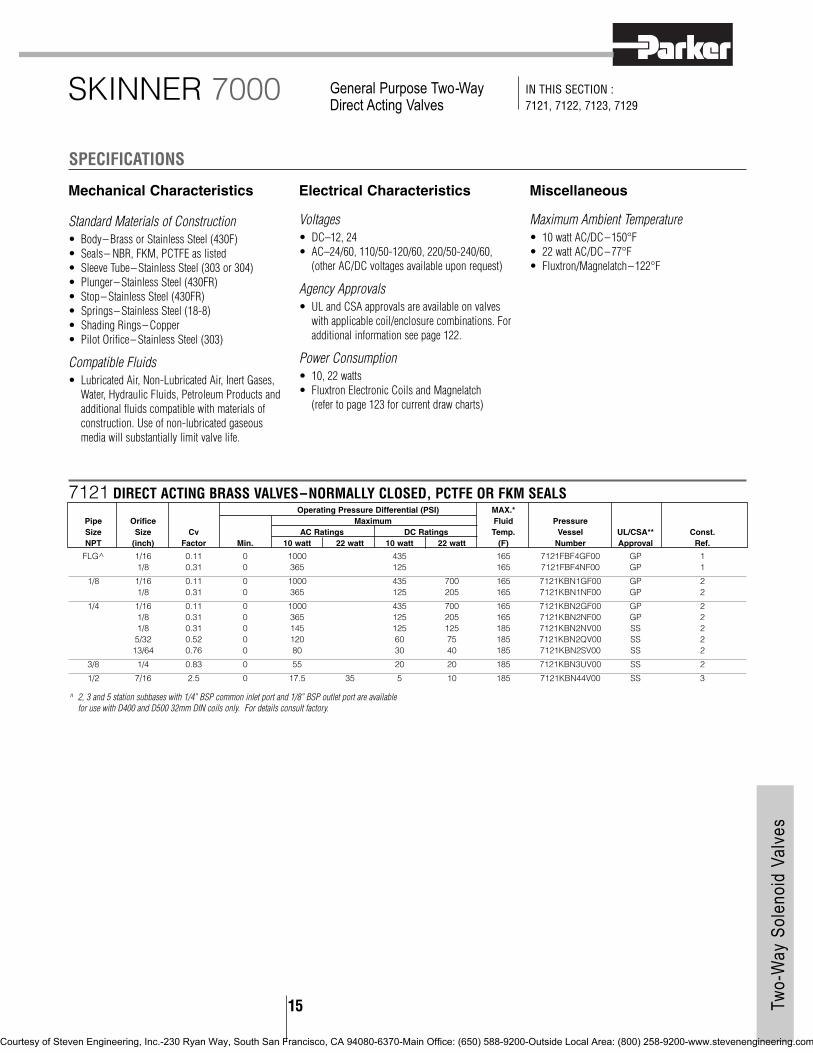
Mechanical Characteristics
Standard Materials of Construction• Body– Brass or Stainless Steel (430F)• Seals– NBR, FKM, PCTFE as listed• Sleeve Tube– Stainless Steel (303 or 304)• Plunger– Stainless Steel (430FR)• Stop– Stainless Steel (430FR)• Springs– Stainless Steel (18-8)• Shading Rings– Copper• Pilot Orifice– Stainless Steel (303)
Compatible Fluids• Lubricated Air, Non-Lubricated Air, Inert Gases,
Water, Hydraulic Fluids, Petroleum Products andadditional fluids compatible with materials ofconstruction. Use of non-lubricated gaseousmedia will substantially limit valve life.
Electrical Characteristics
Voltages• DC–12, 24• AC–24/60, 110/50-120/60, 220/50-240/60,
(other AC/DC voltages available upon request)
Agency Approvals• UL and CSA approvals are available on valves
with applicable coil/enclosure combinations. Foradditional information see page 122.
Power Consumption• 10, 22 watts• Fluxtron Electronic Coils and Magnelatch
(refer to page 123 for current draw charts)
Miscellaneous
Maximum Ambient Temperature• 10 watt AC/DC–150°F• 22 watt AC/DC–77°F• Fluxtron/Magnelatch–122°F
SPECIFICATIONS
SKINNER 7000 General Purpose Two-WayDirect Acting Valves
IN THIS SECTION : 7121, 7122, 7123, 7129
7121 DIRECT ACTING BRASS VALVES–NORMALLY CLOSED, PCTFE OR FKM SEALSOperating Pressure Differential (PSI) MAX.*
Pipe Orifice Maximum Fluid Pressure Size Size Cv AC Ratings DC Ratings Temp. Vessel UL/CSA** Const.NPT (inch) Factor Min. 10 watt 22 watt 10 watt 22 watt (F) Number Approval Ref.
FLG^ 1/16 0.11 0 1000 435 165 7121FBF4GF00 GP 11/8 0.31 0 365 125 165 7121FBF4NF00 GP 1
1/8 1/16 0.11 0 1000 435 700 165 7121KBN1GF00 GP 21/8 0.31 0 365 125 205 165 7121KBN1NF00 GP 2
1/4 1/16 0.11 0 1000 435 700 165 7121KBN2GF00 GP 21/8 0.31 0 365 125 205 165 7121KBN2NF00 GP 21/8 0.31 0 145 125 125 185 7121KBN2NV00 SS 25/32 0.52 0 120 60 75 185 7121KBN2QV00 SS 213/64 0.76 0 80 30 40 185 7121KBN2SV00 SS 2
3/8 1/4 0.83 0 55 20 20 185 7121KBN3UV00 SS 2
1/2 7/16 2.5 0 17.5 35 5 10 185 7121KBN44V00 SS 3
^ 2, 3 and 5 station subbases with 1/4” BSP common inlet port and 1/8” BSP outlet port are availablefor use with D400 and D500 32mm DIN coils only. For details consult factory.
Two-
Way
Sol
enoi
d Va
lves
15
Courtesy of Steven Engineering, Inc.-230 Ryan Way, South San Francisco, CA 94080-6370-Main Office: (650) 588-9200-Outside Local Area: (800) 258-9200-www.stevenengineering.com

16
* Maximum fluid temperatures are provided for Class F coils. Valves with FKM seals (letter “V” in10th position of pressure vessel number) can be used at fluid temperatures up to 240°F on DC and250°F on AC provided a Class H coil is used.
** UL/CSA Approval Information: SS=Safety Shutoff GP=General Purpose Blank=Not Approved
See page 122 for additional agency approval information.5-11PSI is the operating pressure range for bubbletight sealing. Valves may leak if the pressure
ddddifferential falls below 5 PSI. Fluxtron coils not suitable for use with these valves.
#4
General Purpose Two-Way Direct Acting Valves
7000 SeriesDR
AWIN
GS
7121 DIRECT ACTING STAINLESS STEEL VALVES–NORMALLY CLOSED, PCTFE OR NBR SEALS‘5’ Family valves listed below containing NBR seals are also available with FKM seals.
Operating Pressure Differential (PSI) MAX.*Pipe Orifice Maximum Fluid Pressure Size Size Cv AC Ratings DC Ratings Temp. Vessel UL/CSA** Const.NPT (inch) Factor Min. 10 watt 22 watt 10 watt 22 watt (F) Number Approval Ref.
1/8 3/64 0.06 0 1000 520 1000 165 71215SN1EF00 GP 43/64 0.06 0 450 450 185 71215SN1EN00 SS 41/16 0.1 0 700 350 700 165 71215SN1GF00 GP 41/16 0.1 0 350 350 185 71215SN1GN00 SS 43/32 0.18 0 260 650 130 300 165 71215SN1KF00 GP 43/32 0.18 0 275 275 185 71215SN1KN00 SS 41/8 0.28 0 200 520 100 200 165 71215SN1MF00 GP 41/8 0.28 0 200 150 200 185 71215SN1MN00 SS 45/32 0.4 0 110 150 60 130 185 71215SN1QN00 SS 43/16 0.5 0 80 90 25 70 185 71215SN1SN00 SS 41/4 0.75 0 40 70 10 30 185 71215SN1VN00 SS 4
1/4 3/64 0.06 0 1000 520 1000 165 71215SN2EF00 GP 43/64 0.06 0 450 450 185 71215SN2EN00 SS 41/16 0.1 0 700 350 700 165 71215SN2GF00 GP 41/16 0.1 0 350 350 185 71215SN2GN00 SS 43/32 0.18 0 260 650 130 300 165 71215SN2KF00 GP 43/32 0.18 0 275 275 185 71215SN2KN00 SS 41/8 0.28 0 200 520 100 200 165 71215SN2MF00 GP 41/8 0.28 0 200 150 200 185 71215SN2MN00 SS 45/32 0.4 0 110 150 60 130 185 71215SN2QN00 SS 43/16 0.5 0 80 90 25 70 185 71215SN2SN00 SS 41/4 0.75 0 40 70 10 30 185 71215SN2VN00 SS 45/16 1.1 0 20 55 3 10 185 71215SN21N00 SS 5
3/8 3/8 2 0 6 25 5 185 71215SN33N00 SS 63/8 2 5 11 185 71215SN33NHP*** SS 6
Two-
Way
Sol
enoi
d Va
lves #5Port Identification: 2-IN/ 1-OUT Port Identification: 2-IN/ 1-OUT
#10-32U NF2B TH’Dx .25 DP - 2 PLC’S
1
2 2
1
Courtesy of Steven Engineering, Inc.-230 Ryan Way, South San Francisco, CA 94080-6370-Main Office: (650) 588-9200-Outside Local Area: (800) 258-9200-www.stevenengineering.com

17 Two-
Way
Sol
enoi
d Va
lves
General Purpose Two-Way Direct Acting Valves
7000 Series
#6 #1
#2 #3
Port Identification: 1- IN/ 2-OUT
Port Identification: 1- IN/ 2-OUT
DimensionValve H P C L
7121KBN1XXXX 2.63 3.07 1.61 1.577121KBN2XXXX 2.63 3.07 1.61 1.577121KBN3XXXX 2.57 3.08 1.55 1.97“X” denotes multiple digit combinations for brevity.
Port Identification: 2- IN/ 1-OUT
Port Identification: Flow arrow on body indicates flow direction–
ports are not marked.
Courtesy of Steven Engineering, Inc.-230 Ryan Way, South San Francisco, CA 94080-6370-Main Office: (650) 588-9200-Outside Local Area: (800) 258-9200-www.stevenengineering.com

Two-
Way
Sol
enoi
d Va
lves
18
Your design requires consistent, reliable performance for controlling the steam pressure under widely varying conditions. The Skinner Direct Lift Normally Closed, Brass Valve with EPDM seals does the job perfectly.”
General Purpose Two-Way Direct Acting Valves
7000 Series
7122 DIRECT ACTING BRASS VALVES– NORMALLY OPEN, PCTFE SEALSOperating Pressure Differential (PSI) MAX.*
Pipe Orifice Maximum Fluid Pressure Size Size Cv AC Ratings DC Ratings Temp. Vessel UL/CSA** Const.NPT (inch) Factor Min. 10 watt 22 watt 10 watt 22 watt (F) Number Approval Ref.
1/8 1/16 0.11 0 435 435 165 7122KBN1GF00 GP 963/32 0.21 0 175 175 165 7122KBN1LF00 GP 96
1/4 1/16 0.11 0 435 435 165 7122KBN2GF00 GP 963/32 0.21 0 175 175 165 7122KBN2LF00 GP 96
7122 DIRECT ACTING STAINLESS STEEL VALVES–NORMALLY OPEN, PCTFE SEALS5’ Family valves listed below containing NBR seals are also available with FKM seals.
Operating Pressure Differential (PSI) MAX.*Pipe Orifice Maximum Fluid Pressure Size Size Cv AC Ratings DC Ratings Temp. Vessel UL/CSA** Const.NPT (inch) Factor Min. 10 watt 22 watt 10 watt 22 watt (F) Number Approval Ref.
1/8” 3/64 0.05 0 750 750 165 71225SN1EF00 GP 991/16 0.11 0 400 400 165 71225SN1GF00 GP 993/32 0.15 0 170 170 165 71225SN1KF00 GP 99
1/4 3/64 0.05 0 750 750 165 71225SN2EF00 GP 991/16 0.11 0 400 400 165 71225SN2GF00 GP 993/32 0.15 0 170 170 165 71225SN2KF00 GP 99
#96#99
DRAW
INGS
Port Identification: 2- IN/ 1-OUT Port Identification: 1- IN/ 2-OUT
** UL/CSA Approval Information: SS=Safety Shutoff GP=General Purpose Blank=Not ApprovedSee page 122 for additional agency approval information.
Courtesy of Steven Engineering, Inc.-230 Ryan Way, South San Francisco, CA 94080-6370-Main Office: (650) 588-9200-Outside Local Area: (800) 258-9200-www.stevenengineering.com

19 Two-
Way
Sol
enoi
d Va
lves
General Purpose Two-Way Direct Acting Valves
7000 Series
#7
DRAW
INGS
7129 DIRECT ACTING STAINLESS STEEL VALVES–NORMALLY OPEN, NBR SEALS‘5’ Family valves listed below containing NBR seals are also available with FKM seals.
Operating Pressure Differential (PSI) MAX.*Pipe Orifice Maximum Fluid Pressure Size Size Cv AC Ratings DC Ratings Temp. Vessel UL/CSA** Const.NPT (inch) Factor Min. 10 watt 22 watt 10 watt 22 watt (F) Number Approval Ref.
1/8” 3/64 0.05 0 400 400 185 71295SN1ENJ1 GP 71/16 0.11 0 325 325 185 71295SN1GNJ1 GP 73/32 0.15 0 250 250 185 71295SN1KNJ1 GP 7
1/4” 3/64 0.05 0 400 400 185 71295SN2ENJ1 GP 71/16 0.11 0 325 325 185 71295SN2GNJ1 GP 73/32 0.15 0 250 250 185 71295SN2KNJ1 GP 7
Port Identification: 2- IN/ 3-OUT #100
DRAW
INGS
Port Identification: Pressure canbe applied to either port.
* Maximum fluid temperatures are provided for Class F coils. Valves with FKM seals (letter “V” in10th position of pressure vessel number) can be used at fluid temperatures up to 240°F on DC and250°F on AC provided a Class H coil is used.
** UL/CSA Approval Information: SS=Safety Shutoff GP=General Purpose Blank=Not ApprovedSee page 122 for additional agency approval information.
7123 DIRECT ACTING STAINLESS STEEL VALVES–DUAL PURPOSE, NBR SEALS ‘5’ Family valves listed below containing NBR seals are also available with FKM seals.
Operating Pressure Differential (PSI) MAX.*Pipe Orifice Maximum Fluid Pressure Size Size Cv AC Ratings DC Ratings Temp. Vessel UL/CSA** Const.NPT (inch) Factor Min. 10 watt 22 watt 10 watt 22 watt (F) Number Approval Ref.
1/8 1/32 0.02 0 400 400 185 71235SN1AN00 SS 1003/64 0.06 0 180 180 185 71235SN1EN00 SS 1001/16 0.1 0 110 110 185 71235SN1GN00 SS 1003/32 0.17 0 70 70 185 71235SN1KN00 SS 1001/8 0.28 0 45 45 185 71235SN1MN00 SS 100
1/4 1/32 0.02 0 400 400 185 71235SN2AN00 SS 1003/64 0.06 0 180 180 185 71235SN2EN00 SS 1001/16 0.1 0 110 110 185 71235SN2GN00 SS 1003/32 0.17 0 70 70 185 71235SN2KN00 SS 1001/8 0.28 0 45 45 185 71235SN2MN00 SS 100
Courtesy of Steven Engineering, Inc.-230 Ryan Way, South San Francisco, CA 94080-6370-Main Office: (650) 588-9200-Outside Local Area: (800) 258-9200-www.stevenengineering.com

20Two-
Way
Sol
enoi
d Va
lves
Mechanical Characteristics
Standard Materials of Construction• Body–Brass or Stainless Steel (316 or 430F)• Seals–NBR, FKM as listed• Sleeve Tube–Stainless Steel (303 or 304)• Plunger–Stainless Steel (430FR)• Stop–Stainless Steel (430FR)• Springs–Stainless Steel (18-8)• Shading Ring–Copper• Pilot Orifice–Stainless Steel (303)
Compatible Fluids• Lubricated Air, Non-Lubricated Air, Inert Gases,
Water, Hydraulic Fluids, Petroleum Products andadditional fluids compatible with materials ofconstruction. Use of non-lubricated gaseousmedia will substantially limit valve life.
Electrical Characteristics
Voltages• DC– 12, 24• AC– 24/60, 110/50-120/60, 220/50-
240/60,(other AC/DC voltages available uponrequest)
Power Consumption• 10, 22 watts• Fluxtron* Electronic Coils and Magnelatch
Agency Approvals• UL and CSA approvals are available on valves
with applicable coil/enclosure combinations. Foradditional information see page 122.
Miscellaneous
Maximum Ambient Temperature• 10 watt AC/DC– 150°F• 22 watt AC/DC– 77°F• Fluxtron*/Magnelatch–122°F
* Fluxtron coils not for use on direct liftvalves.
SPECIFICATIONS
SKINNER 7000 Series General Purpose Two-Way Direct Liftand Pilot Operated Valves
IN THIS SECTION : 7221, 7222, 7321, 7322, 7423
* Direct lift valves will open at zero differential pressure, however full flow through the valve will notbe safely achieved. If full flow is required at zero differential pressure, consult Skinner.
** Maximum fluid temperatures are provided for Class F coils. Valves with FKM seals (letter “V” in10th position of pressure vessel number) can be used at fluid temperatures up to 240°F on DC and
250°F on AC provided a Class H coil is used.*** UL/CSA Approval Information: SS=Safety Shutoff GP=General Purpose Blank=Not Approved
See page 122 for additional agency approval information.
For Direct Lift Valve With 11/2 NPT Process Connection Please Go To Page 44.
7221 DIRECT LIFT STAINLESS STEEL VALVES– NORMALLY CLOSED, FKM SEALSOperating Pressure Differential (PSI) MAX.***
Pipe Orifice Maximum Fluid Pressure Size Size Cv AC Ratings DC Ratings Temp. Vessel UL/CSA** Const.NPT (inch) Factor Min.* 10 watt 22 watt 10 watt 22 watt (F) Number Approval Ref.
3/8” 5/8 3.0 0 100 40 185 72218RN3TV00 SS 8
1/2” 5/8 4.0 0 100 40 185 72218RN4UV00 SS 8
3/4” 3/4 5.0 0 100 40 185 72218RN5VV00 SS 8
7221 DIRECT LIFT BRASS VALVES– NORMALLY CLOSED, NBR SEALS ‘8’ and ‘G’ Family valves listed below are also available in FKM Seals.
Operating Pressure Differential (PSI) MAX.**Pipe* Orifice Maximum Fluid Pressure Size Size Cv AC Ratings DC Ratings Temp. Vessel UL/CSA*** Const.NPT (inch) Factor Min.* 10 watt 22 watt 10 watt 22 watt (F) Number Approval Ref.
3/8” 5/8 3.0 0 100 40 185 72218BN3TN00 SS 819/32 4.4 0 230 100 185 7221GBN3VN00 SS 9
1/2” 5/8 4.0 0 100 40 185 72218BN4UN00 SS 819/32 4.4 0 230 100 185 7221GBN4VN00 SS 9
3/4” 3/4 5.0 0 100 40 185 72218BN5VN00 SS 819/32 5.5 0 230 100 185 7221GBN51N00 SS 9
1” 19/32 5.5 0 230 100 185 7221GBN61N00 SS 91 11.7 0 230 85 185 7221GBN64N00 SS 9
Courtesy of Steven Engineering, Inc.-230 Ryan Way, South San Francisco, CA 94080-6370-Main Office: (650) 588-9200-Outside Local Area: (800) 258-9200-www.stevenengineering.com

21 Two-
Way
Sol
enoi
d Va
lves
#8
DRAW
INGS
General Purpose Two-Way Direct Liftand Pilot Operated Valves
7000 Series
* Direct lift valves will open at zero differential pressure, however full flow through the valve will notbe safely achieved. If full flow is required at zero differential pressure, consult Skinner.
** Maximum fluid temperatures are provided for Class F coils. Valves with FKM seals (letter “V” in10th position of pressure vessel number) can be used at fluid temperatures up to 240°F on DC and250°F on AC provided a Class H coil is used.
*** UL/CSA Approval Information: SS=Safety Shutoff GP=General Purpose Blank=Not ApprovedSee page 122 for additional agency approval information.
+ Rating suitable for all 22 watt integrated coils except D300 DIN coil. Consult Skinner Valve forapplication review.
#9
7222 DIRECT LIFT BRASS VALVES– NORMALLY OPEN, FKM SEALSOperating Pressure Differential (PSI) MAX.**
Pipe Orifice Maximum Fluid Pressure Size Size Cv AC Ratings DC Ratings Temp. Vessel UL/CSA*** Const.NPT (inch) Factor Min.* 10 watt 22 watt 10 watt 22 watt (F) Number Approval Ref.
3/8” 5/8 3.0 0 125+ 125 185 72228BN3TV00 GP 102
1/2” 5/8 4.0 0 125+ 125 185 72228BN4UV00 GP 102
3/4” 3/4 5.0 0 125+ 125 185 72228BN5VV00 GP 102
7222 DIRECT LIFT STAINLESS STEEL VALVES– NORMALLY OPEN, FKM SEALSOperating Pressure Differential (PSI) MAX.**
Pipe Orifice Maximum Fluid Pressure Size Size Cv AC Ratings DC Ratings Temp. Vessel UL/CSA*** Const.NPT (inch) Factor Min.* 10 watt 22 watt 10 watt 22 watt (F) Number Approval Ref.
3/8” 5/8 3.0 0 125+ 125 185 72228RN3TV00 GP 102
1/2” 5/8 4.0 0 125+ 125 185 72228RN4UV00 GP 102
3/4” 3/4 5.0 0 125+ 125 185 72228RN5VV00 GP 102
#102
DRAW
INGS
Port Identification: P- IN/ - -OUT
DimensionValve H P C L
72228BN3TXXX 4.04 3.49 2.43 2.6472228BN4UXXX 4.04 3.49 2.43 2.6472228BN5VXXX 4.24 3.58 2.52 2.7272228RN3TXXX 4.04 3.49 2.43 2.6472228RN4UXXX 4.04 3.49 2.43 2.6472228RN5VXXX 4.24 3.58 2.52 2.72“X” denotes multiple digit combinations for brevity.
Port Identification: P- IN/ - -OUT
DimensionValve H P C L
72218BN3TXXX 3.78 3.23 2.21 2.6472218BN4UXXX 3.78 3.23 2.21 2.6472218BN5VXXX 3.99 3.33 2.31 2.7272218RN3TXXX 3.99 3.33 2.31 2.7272218RN4UXXX 3.99 3.33 2.31 2.7272218RN5VXXX 3.99 3.33 2.31 2.72“X” denotes multiple digit combinations for brevity.
DimensionValve H P C L W
7221GBN3VXXX 3.66 3.07 2.06 2.95 2.097221GBN4VXXX 3.66 3.07 2.06 2.95 2.097221GBN51XXX 3.75 3.07 2.06 3.15 2.097221GBN61XXX 4.03 3.15 2.12 3.35 2.097221GBN64XXX 4.25 3.35 2.34 3.94 2.75“X” denotes multiple digit combinations for brevity.
Port Identification: Flow arrow on body indicates flow direction–
ports are not marked.
Courtesy of Steven Engineering, Inc.-230 Ryan Way, South San Francisco, CA 94080-6370-Main Office: (650) 588-9200-Outside Local Area: (800) 258-9200-www.stevenengineering.com

22Two-
Way
Sol
enoi
d Va
lves
* Pilot operated valves require the minimum pressure differential specified for proper valveoperation.
** Maximum fluid temperatures are provided for Class F coils. Valves with FKM seals (letter “V” in10th position of pressure vessel number) can be used at fluid temperatures up to 240°F on DC
and 250°F on AC provided a Class H coil is used.*** UL/CSA Approval Information: SS=Safety Shutoff GP=General Purpose Blank=Not Approved
See page 122 for additional agency approval information.1/4”-’2’ Family SS valve also available with FKM seals.
General Purpose Two-Way Direct Liftand Pilot Operated Valves
7000 Series
7321 PILOT OPERATED BRASS VALVES– NORMALLY CLOSED, NBR SEALS ‘K’, ‘8’ and 1/4” ‘2’ Family valves also available with FKM seals
Operating Pressure Differential (PSI) MAX.**Pipe Orifice Maximum Fluid PressureSize Size Cv AC Ratings DC Ratings Temp. Vessel UL/CSA*** Const.NPT (inch) Factor Min.* 10 watt 22 watt 10 watt 22 watt (F) Number Approval Ref.
1/4” 1/4 0.76 5 300 300 185 73212BN2MN00 SS 107/16 2.0 3 150 60 150 185 7321KBN2RN00 SS 98
3/8” 1/2 2.4 5 300 300 185 73212BN3SN00 SS 115/8 3.0 5 150 150 185 73218BN3TN00 SS 127/16 2.5 3 150 60 150 185 7321KBN3SN00 SS 98
1/2” 1/2 2.8 5 300 300 185 73212BN4TN00 SS 115/8 4.0 5 150 150 185 73218BN4UN00 SS 127/16 2.5 3 150 60 150 185 7321KBN4SN00 SS 98
3/4” 3/4 7.3 5 300 300 185 73212BN52N00 SS 133/4 5.0 5 150 150 185 73218BN5VN00 SS 12
25/32 9.6 5 230 230 185 7321GBN53N00 SS 14
1” 1 11.0 5 300 300 185 73212BN63N00 SS 131 1/16 13.5 5 125 125 185 73218BN64N00 SS 15
1 12.5 5 230 230 185 7321GBN64N00 SS 14
1 1/4” 1 1/8 15.0 5 125 125 185 73218BN75N00 SS 151 1/8 19.3 5 230 230 185 7321GBN76N00 SS 14
1 1/2” 1 1/4 22.5 5 125 125 185 73218BN87N00 SS 161 9/16 29.0 5 230 200 230 185 7321GBN88N00 SS 14
2” 1 9/16 38.6 5 230 200 230 185 7321GBN99N00 SS 14
#12
DRAW
INGS
7321 PILOT OPERATED STAINLESS STEEL VALVES–NORMALLY CLOSED, NBR SEALSOperating Pressure Differential (PSI) MAX.**
Pipe Orifice Maximum Fluid Pressure Size Size Cv AC Ratings DC Ratings Temp. Vessel UL/CSA*** Const.NPT (inch) Factor Min.* 10 watt 22 watt 10 watt 22 watt (F) Number Approval Ref.
1/4” 1/4 0.76 5 300 300 185 73212SN2MN00 SS 17
#98
DimensionValve H P C L
7321KBN4SXXX 3.56 2.97 1.96 2.177321KBN2RXXX 3.56 2.97 1.96 1.977321KBN3SXXX 3.56 2.97 1.96 1.97“X” denotes multiple digit combinations for brevity.
Flow arrow on body indicates flow direction–ports are not marked.
Port Identification: P- IN/ - -OUT
DimensionValve H P C L R
73218BN3TXXX 4.38 3.84 2.81 2.64 1.3973218BN4UXXX 4.38 3.84 2.81 2.64 1.3973218BN5VXXX 4.59 3.94 2.91 2.72 1.43“X” denotes multiple digit combinations for brevity.
Courtesy of Steven Engineering, Inc.-230 Ryan Way, South San Francisco, CA 94080-6370-Main Office: (650) 588-9200-Outside Local Area: (800) 258-9200-www.stevenengineering.com

23 Two-
Way
Sol
enoi
d Va
lves
#14
#15
General Purpose Two-Way Direct Liftand Pilot Operated Valves
7000 Series
#11 Port Identification: P- IN/ - -OUT
DimensionValve H P C
73218BN64XXX 5.45 4.59 3.5773218BN75XXX 5.74 2.97 1.96“X” denotes multiple digit combinationsfor brevity.
Port Identification: P- IN/ - -OUT
Port Identification: 2- IN/ 1-OUT Port Identification: P- IN/ A-OUT
Port Identification: IN-IN/ OUT-OUT
#16
#17 #10
Port Identification: P- IN/ - -OUT
DimensionValve H P C L W
7321GBN53XXX 4.75 3.86 2.84 3.94 2.757321GBN64XXX 4.75 3.86 2.84 3.94 2.757321GBN76XXX 5.41 4.11 3.09 4.33 2.757321GBN88XXX 5.66 4.37 3.35 5.51 3.907321GBN99XXX 6.25 4.60 3.58 5.91 3.90“X” denotes multiple digit combinations for brevity.Flow arrow on body indicates flow direction–ports arenot marked.
Courtesy of Steven Engineering, Inc.-230 Ryan Way, South San Francisco, CA 94080-6370-Main Office: (650) 588-9200-Outside Local Area: (800) 258-9200-www.stevenengineering.com

24Two-
Way
Sol
enoi
d Va
lves
#18
* Pilot operated valves require the minimum pressure differential specified for proper valveoperation.
** UL/CSA Approval Information: SS=Safety Shutoff GP=General Purpose Blank=Not Approved
See page 122 for additional agency approval information.NOTE: See Electrical options section on page 121 for timer available for these valves. These valvesare rated for intermittent duty cycle applications only.
DRAW
INGS
General Purpose Two-Way Direct Liftand Pilot Operated Valves
7000 Series
7321 PILOT OPERATED BRASS TIMER DRAIN VALVES–NORMALLY CLOSED, FKM SEALSOperating Pressure Differential (PSI) MAX.
Pipe Orifice Maximum Fluid Pressure Size Size Cv AC Ratings DC Ratings Temp. Vessel UL/CSA** Const.NPT (inch) Factor Min.* 10 watt 22 watt 10 watt 22 watt (F) Number Approval Ref.
1/4” 7/16 1.75 3 300 45 210 7321KBY61640 SS 183/8” 7/16 2.5 3 300 45 210 7321KBY63200 SS 181/2” 7/16 2.7 3 300 45 210 7321KBY6320A SS 18
#13
Dimension Port IdentificationValve H P C L W IN OUT
73212BN52N00 5.81 4.62 3.59 3.62 3.09 IN OUT73212BN63N00 6.22 4.89 3.87 4.31 3.45 P A
Port Identification: Flow arrow on body indicates flow direction–
ports are not marked.
Courtesy of Steven Engineering, Inc.-230 Ryan Way, South San Francisco, CA 94080-6370-Main Office: (650) 588-9200-Outside Local Area: (800) 258-9200-www.stevenengineering.com

25 Two-
Way
Sol
enoi
d Va
lves
General Purpose Two-Way Direct Liftand Pilot Operated Valves
7000 Series
* Pilot operated valves require the minimum pressure differential specified for proper valveoperation.
** Maximum fluid temperatures are provided for Class F coils. Valves with FKM seals (letter “V” in10th position of pressure vessel number) can be used at fluid temperatures up to 240°F on DC
and 250°F on AC provided a Class H coil is used.*** UL/CSA Approval Information: SS=Safety Shutoff GP=General Purpose Blank=Not Approved
See page 122 for additional agency approval information.1/4”– ‘2’ Family valves listed are also available with FKM seals.
7322 PILOT OPERATED STAINLESS STEEL VALVES–NORMALLY OPEN, NBR SEALOperating Pressure Differential (PSI) MAX.**
Pipe Orifice Maximum Fluid Pressure Size Size Cv AC Ratings DC Ratings Temp. Vessel UL/CSA*** Const.NPT (inch) Factor Min.* 10 watt 22 watt 10 watt 22 watt (F) Number Approval Ref.
1/4” 1/4 0.76 5 200 200 185 73222SN2MN00 GP 112
7322 PILOT OPERATED BRASS VALVES– NORMALLY OPEN, NBR SEALS‘8’ and 1/4” ‘2’ Family valves listed below are also available in FKM Seals.
Operating Pressure Differential (PSI) MAX.**Pipe Orifice Maximum Fluid Pressure Size Size Cv AC Ratings DC Ratings Temp. Vessel UL/CSA*** Const.NPT (inch) Factor Min.* 10 watt 22 watt 10 watt 22 watt (F) Number Approval Ref.
1/4” 1/4 0.76 5 200 200 185 73222BN2MN00 GP 104
3/8” 1/2 2.4 5 200 200 185 73222BN3SN00 GP 1055/8 3.0 5 150 150 185 73228BN3TN00 GP 106
1/2” 1/2 2.8 5 200 200 185 73222BN4TN00 GP 1055/8 4.0 5 150 150 185 73228BN4UN00 GP 106
3/4” 3/4 7.3 5 200 200 185 73222BN52N00 GP 1073/4 5.0 5 150 150 185 73228BN5VN00 GP 106
25/32 9.6 5 230 230 185 7322GBN53N00 GP 108
1” 1 11.0 5 200 200 185 73222BN63N00 GP 1071 1/16 13.5 5 125 125 185 73228BN64N00 GP 110
1 12.5 5 230 230 185 7322GBN64N00 GP 108
1 1/4” 1 1/8 15.0 5 125 125 185 73228BN75N00 GP 1101 1/8 19.3 5 230 230 185 7322GBN76N00 GP 108
1 1/2” 1 1/4 22.5 5 125 125 185 73228BN87N00 GP 1111 9/16 29.0 5 170 170 185 7322GBN88N00 GP 108
2” 1 9/16 38.6 5 170 170 185 7322GBN99N00 GP 108
#108 #106
DRAW
INGS Dimension
Valve H P C L W7322GBN53XXX 4.75 3.86 2.84 3.94 2.757322GBN64XXX 4.75 3.86 2.84 3.94 2.757322GBN76XXX 5.41 4.11 3.09 4.33 2.757322GBN88XXX 5.66 4.37 3.35 5.51 3.907322GBN99XXX 6.25 4.60 3.58 5.91 3.90“X” denotes multiple digit combinations for brevity.
Port Identification: P- IN/ - - OUT
DimensionValve H P C L R
73228BN3TXXX 4.62 4.07 3.01 2.64 1.3973228BN4UXXX 4.62 4.07 3.01 2.64 1.3973228BN5VXXX 4.83 4.17 3.11 2.72 1.43“X” denotes multiple digit combinations for brevity.
Port Identification: Flow arrow on body indicates flow direction–
ports are not marked.
Courtesy of Steven Engineering, Inc.-230 Ryan Way, South San Francisco, CA 94080-6370-Main Office: (650) 588-9200-Outside Local Area: (800) 258-9200-www.stevenengineering.com

26Two-
Way
Sol
enoi
d Va
lves
General Purpose Two-Way Direct Liftand Pilot Operated Valves
7000 Series
#107 #105
#110 #111
#112 #104
Port Identification: P- IN/ - -OUT
DimensionValve H P C
73228BN64XXX 5.69 4.83 3.7773228BN75XXX 5.97 4.97 3.91“X” denotes multiple digit combinationsfor brevity.
Port Identification: 2- IN/ 1-OUT Port Identification: P- IN/ A-OUT
Port Identification: IN-IN/ OUT-OUT
Port Identification: P- IN/ - -OUT
Dimension Port IdentificationValve H P C L W IN OUT
73222BN52N00 6.04 4.85 3.79 3.62 3.09 IN OUT73222BN63N00 6.46 5.13 4.07 4.31 3.45 P A
Courtesy of Steven Engineering, Inc.-230 Ryan Way, South San Francisco, CA 94080-6370-Main Office: (650) 588-9200-Outside Local Area: (800) 258-9200-www.stevenengineering.com

27 Two-
Way
Sol
enoi
d Va
lves
General Purpose Two-Way Direct Liftand Pilot Operated Valves
7000 Series
#19 #20
7423 PILOT OPERATED BRASS VALVES– DUAL PURPOSE, NBR SEALSOperating Pressure Differential (PSI) MAX.*
Pipe Orifice Maximum Fluid Pressure Size Size Cv AC Ratings DC Ratings Temp. Vessel UL/CSA** Const.NPT (inch) Factor Min.* 10 watt 22 watt 10 watt 22 watt (F) Number Approval Ref.
3/8” 1/2 2.4 0 150 150 185 74232BN3SNJ1 GP 19
1/2” 1/2 2.8 0 150 150 185 74232BN4TNJ1 GP 19
3/4” 3/4 7.3 0 150 150 185 74232BN52NJ1 GP 20
1” 1 11.0 0 150 150 185 74232BN63NJ1 GP 20
* Maximum fluid temperatures are provided for Class F coils. Valves with FKM seals (letter ‘V’ in 10thposition of pressure vessel number) can be used at fluid temperatures up to 240°F on DC and250°F on AC provided a Class H coil is used.Note: External Pilot Pressure valves require a minimum external pilot pressure equal to the main linepressure plus 10 PSI. Maximum external pilot pressure is 145 PSI for vacuum applications, and 160
PSI for pressure applications.Pressure ratings may be reduced, however. Consult factory for details.
** UL/CSA Approval information: SS=Safety Shutoff GP=General Purpose BLANK = Not ApprovedSee page 122 for additional agency approval information.
DRAW
INGS Dimension Port Identification
Valve H P C L W S IN OUT74232BN52NJ1 6.78 5.59 3.59 3.62 3.09 2.28 IN OUT74232BN63NJ1 7.19 5.86 3.87 4.31 3.45 2.56 P AValve can be normally closed or normally open, depending on piping of external pilot.
NORMALLY OPENPort Identification: IN-IN/ OUT-OUTNote: Valve may be normally closed
or normally open, depending onpiping of external pilot.
NORMALLY CLOSED
NORMALLY CLOSED NORMALLY OPEN
Courtesy of Steven Engineering, Inc.-230 Ryan Way, South San Francisco, CA 94080-6370-Main Office: (650) 588-9200-Outside Local Area: (800) 258-9200-www.stevenengineering.com

28Two-
Way
Sol
enoi
d Va
lves
SKINNER 7000 Series Hot Water and Steam Two-Way, Direct Acting, Direct Lift and Pilot Operated Valves
Mechanical Characteristics
Standard Materials of Construction• Body– Brass or Stainless Steel (316 or 430F)• Seals– PTFE, EPDM as listed• Sleeve Tube– Stainless Steel (303 or 304)• Plunger– Stainless Steel (430FR)• Piston– Brass• Piston Seal– PTFE Composite• Piston Guide– Teflon Composite• Stop– Stainless Steel (430FR)• Springs– Stainless Steel (18-8 or 17-7PH))• Shading Ring– Copper
Compatible Fluids• Steam to 353°F, Hot Water to 210°F
Electrical Characteristics
Voltages• DC– 12, 24• AC– 24/60, 110/50-120/60, 220/50-240/60,
(other AC/DC voltages available upon request)
Power Consumption• 10, 22 watts• Fluxtron* Electronic Coils and Magnelatch
Agency Approvals• UL and CSA approvals are available on valves
with applicable coil/enclosure combinations. Foradditional information see page 122.
Miscellaneous
Maximum Ambient Temperature• 10 watt AC/DC– 150°F(-E00 valves), 122°F
(-ES0 valves), 77°F(-TS0 valves)• 22 watt AC/DC– 77°F• Fluxtron*/Magnelatch– 122°F
Fluxtron coils not suitable for use on directlift valves. Fluxtron and Magnelatch coilsnot suitable for use on valves rated forsteam service (S0).
SPECIFICATIONS
Valves with ‘S0’ in last two digits of pressure vessel number are rated for steam applications.
DIRECT ACTING BRASS VALVES–NORMALLY CLOSED, EPDM SEALSOperating Pressure Differential (PSI) MAX.
Pipe Orifice Maximum Fluid Pressure**Size Size Cv AC Ratings DC Ratings Temp. Vessel UL/CSA*** Const.NPT (inch) Factor Min.* 10 watt 22 watt 10 watt 22 watt (F) Number Approval Ref.
1/4 13/64 0.76 0 100 40 100 210 7121KBN2SE00 GP 213/64 0.76 0 40 40 285 7121KBN2SES0 GP 2
DIRECT LIFT BRASS VALVES–NORMALLY CLOSED, EPDM SEALSOperating Pressure Differential (PSI) MAX.
Pipe Orifice Maximum Fluid Pressure**Size Size Cv AC Ratings DC Ratings Temp. Vessel UL/CSA*** Const.NPT (inch) Factor Min.* 10 watt 22 watt 10 watt 22 watt (F) Number Approval Ref.
3/8” 5/8 3.0 0 100 40 210 72218BN3TE00 GP 85/8 3.0 0 50 297 72218BN3TES0 GP 8
19/32 4.4 0 150 100 210 7221GBN3VE00 GP 919/32 4.4 0 45 45 293 7221GBN3VES0 GP 9
1/2” 5/8 4.0 0 100 40 210 72218BN4UE00 GP 85/8 4.0 0 50 297 72218BN4UES0 GP 8
19/32 4.4 0 150 100 210 7221GBN4VE00 GP 919/32 4.4 0 45 45 293 7221GBN4VES0 GP 9
3/4” 3/4 5.0 0 100 40 210 72218BN5VE00 GP 83/4 5.0 0 50 297 72218BN5VES0 GP 8
19/32 5.5 0 150 100 210 7221GBN51E00 GP 919/32 5.5 0 45 45 293 7221GBN51ES0 GP 9
1” 5/8 5.5 0 150 100 210 7221GBN61E00 GP 95/8 5.5 0 45 45 293 7221GBN61ES0 GP 91 11.7 0 150 100 210 7221GBN64E00 GP 91 11.7 0 45 45 293 7221GBN64ES0 GP 9
•
Courtesy of Steven Engineering, Inc.-230 Ryan Way, South San Francisco, CA 94080-6370-Main Office: (650) 588-9200-Outside Local Area: (800) 258-9200-www.stevenengineering.com

29 Two-
Way
Sol
enoi
d Va
lves
DIRECT LIFT BRASS VALVES– NORMALLY OPEN, EPDM SEALSOperating Pressure Differential (PSI) MAX.
Pipe Orifice Maximum Fluid Pressure**Size Size Cv AC Ratings DC Ratings Temp. Vessel UL/CSA*** Const.NPT (inch) Factor Min.* 10 watt 22 watt 10 watt 22 watt (F) Number Approval Ref.
3/8” 5/8 3.0 0 125 125 210 72228BN3TE00 GP 1025/8 3.0 0 50 297 72228BN3TES0 GP 102
1/2” 5/8 4.0 0 125 125 210 72228BN4UE00 GP 1025/8 4.0 0 50 297 72228BN4UES0 GP 102
3/4” 3/4 5.0 0 125 125 210 72228BN5VE00 GP 1023/4 5.0 0 50 297 72228BN5VES0 GP 102
Hot Water and Steam Two-Way, Direct Acting, Direct Lift and Pilot Operated Valves
7000 Series
PILOT OPERATED BRASS VALVES–NORMALLY CLOSED, EPDM OR PTFE SEALSOperating Pressure Differential (PSI) MAX.
Pipe Orifice Maximum Fluid Pressure**Size Size Cv AC Ratings DC Ratings Temp. Vessel UL/CSA*** Const.NPT (inch) Factor Min.* 10 watt 22 watt 10 watt 22 watt (F) Number Approval Ref.
1/4” 7/16 2.0 3 150 60 150 210 7321KBN2RE00 GP 987/16 2.0 3 45 45 293 7321KBN2RES0 GP 98
3/8” 5/8 3.0 5 150 150 210 73218BN3TE00 GP 125/8 3.0 5 50 50 297 73218BN3TES0 GP 125/8 3.0 3 125 353 73218BN3TTS0 GP 217/16 2.5 3 150 60 150 210 7321KBN3SE00 GP 987/16 2.5 3 45 45 293 7321KBN3SES0 GP 98
1/2” 5/8 4.0 5 150 150 210 73218BN4UE00 GP 125/8 4.0 5 50 50 297 73218BN4UES0 GP 125/8 4.0 3 125 353 73218BN4UTS0 GP 217/16 2.5 3 150 60 150 210 7321KBN4SE00 GP 987/16 2.5 3 45 45 293 7321KBN4SES0 GP 98
3/4” 3/4 5.0 5 150 150 210 73218BN5VE00 GP 123/4 5.0 5 50 50 297 73218BN5VES0 GP 125/8 4.5 3 125 353 73218BN5VTS0 GP 21
1” 1 1/16 13.5 5 125 125 210 73218BN64E00 GP 151 1/16 13.5 5 50 50 297 73218BN64ES0 GP 151 1/16 13.5 5 125 353 73218BN64TS0 GP 22
1 1/4” 1 1/8 15.0 5 125 125 210 73218BN75E00 GP 151 1/8 15.0 5 50 50 297 73218BN75ES0 GP 151 1/8 16.0 5 125 353 73218BN75TS0 GP 22
1 1/2” 1 1/4 22.5 5 125 125 210 73218BN87E00 GP 161 1/4 22.5 5 50 50 297 73218BN87ES0 GP 161 1/4 22.5 5 125 353 73218BN87TS0 GP 23
DIRECT LIFT STAINLESS STEEL VALVES– NORMALLY CLOSED, EPDM SEALSOperating Pressure Differential (PSI) MAX.
Pipe Orifice Maximum Fluid Pressure**Size Size Cv AC Ratings DC Ratings Temp. Vessel UL/CSA*** Const.NPT (inch) Factor Min.* 10 watt 22 watt 10 watt 22 watt (F) Number Approval Ref.
3/8” 5/8 3.0 0 100 40 210 72218RN3TE00 GP 85/8 3.0 0 50 297 72218RN3TES0 GP 8
1/2” 5/8 4.0 0 100 40 210 72218RN4UE00 GP 85/8 4.0 0 50 297 72218RN4UES0 GP 8
3/4” 3/4 5.0 0 100 40 210 72218RN5VE00 GP 83/4 5.0 0 50 297 72218RN5VES0 GP 8
DIRECT LIFT STAINLESS STEEL VALVES– NORMALLY OPEN, EPDM SEALSOperating Pressure Differential (PSI) MAX.
Pipe Orifice Maximum Fluid Pressure**Size Size Cv AC Ratings DC Ratings Temp. Vessel UL/CSA*** Const.NPT (inch) Factor Min.* 10 watt 22 watt 10 watt 22 watt (F) Number Approval Ref.
3/8” 5/8 3.0 0 125 125 210 72228RN3TE00 GP 1025/8 3.0 0 50 297 72228RN3TES0 GP 102
1/2” 5/8 4.0 0 125 125 210 72228RN4UE00 GP 1025/8 4.0 0 50 297 72228RN4UES0 GP 102
3/4” 3/4 5.0 0 125 125 210 72228RN5VE00 GP 1023/4 5.0 0 50 297 72228RN5VES0 GP 102
Courtesy of Steven Engineering, Inc.-230 Ryan Way, South San Francisco, CA 94080-6370-Main Office: (650) 588-9200-Outside Local Area: (800) 258-9200-www.stevenengineering.com
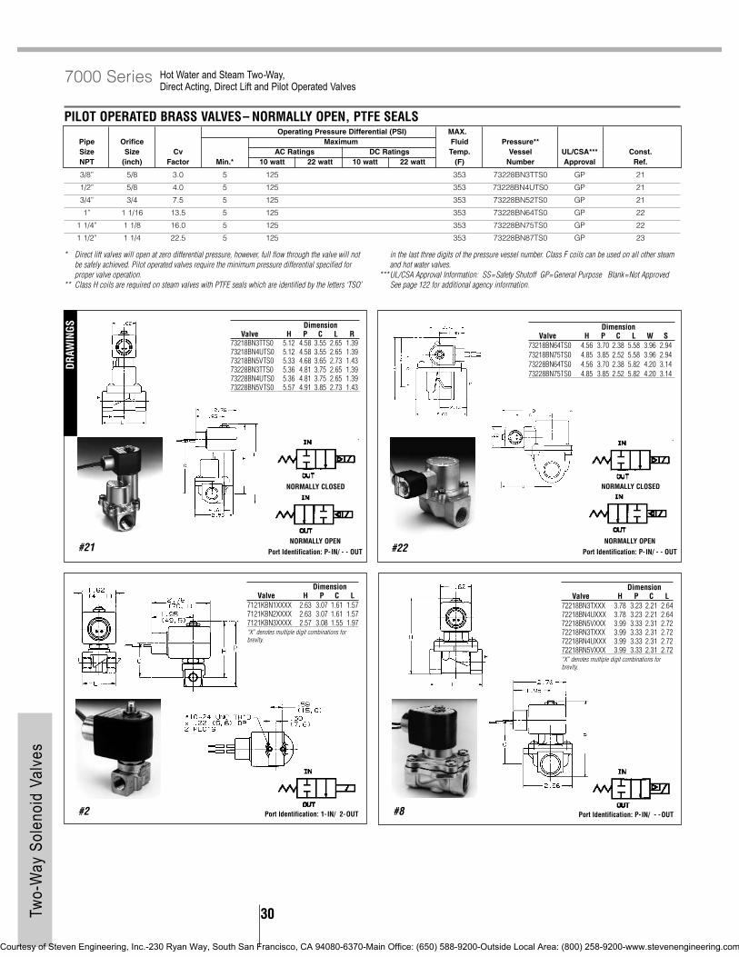
30Two-
Way
Sol
enoi
d Va
lves
#21
* Direct lift valves will open at zero differential pressure, however, full flow through the valve will notbe safely achieved. Pilot operated valves require the minimum pressure differential specified forproper valve operation.
** Class H coils are required on steam valves with PTFE seals which are identified by the letters ‘TSO’
in the last three digits of the pressure vessel number. Class F coils can be used on all other steamand hot water valves.
***UL/CSA Approval Information: SS=Safety Shutoff GP=General Purpose Blank=Not ApprovedSee page 122 for additional agency information.
#22
Hot Water and Steam Two-Way, Direct Acting, Direct Lift and Pilot Operated Valves
7000 Series
PILOT OPERATED BRASS VALVES– NORMALLY OPEN, PTFE SEALSOperating Pressure Differential (PSI) MAX.
Pipe Orifice Maximum Fluid Pressure**Size Size Cv AC Ratings DC Ratings Temp. Vessel UL/CSA*** Const.NPT (inch) Factor Min.* 10 watt 22 watt 10 watt 22 watt (F) Number Approval Ref.
3/8” 5/8 3.0 5 125 353 73228BN3TTS0 GP 21
1/2” 5/8 4.0 5 125 353 73228BN4UTS0 GP 21
3/4” 3/4 7.5 5 125 353 73228BN52TS0 GP 21
1” 1 1/16 13.5 5 125 353 73228BN64TS0 GP 22
1 1/4” 1 1/8 16.0 5 125 353 73228BN75TS0 GP 22
1 1/2” 1 1/4 22.5 5 125 353 73228BN87TS0 GP 23
NORMALLY OPENPort Identification: P- IN/ - - OUT
NORMALLY OPENPort Identification: P- IN/ - - OUT
DimensionValve H P C L R
73218BN3TTS0 5.12 4.58 3.55 2.65 1.3973218BN4UTS0 5.12 4.58 3.55 2.65 1.3973218BN5VTS0 5.33 4.68 3.65 2.73 1.4373228BN3TTS0 5.36 4.81 3.75 2.65 1.3973228BN4UTS0 5.36 4.81 3.75 2.65 1.3973228BN5VTS0 5.57 4.91 3.85 2.73 1.43
DimensionValve H P C L W S
73218BN64TS0 4.56 3.70 2.38 5.58 3.96 2.9473218BN75TS0 4.85 3.85 2.52 5.58 3.96 2.9473228BN64TS0 4.56 3.70 2.38 5.82 4.20 3.1473228BN75TS0 4.85 3.85 2.52 5.82 4.20 3.14
#2 Port Identification: 1- IN/ 2-OUT
DimensionValve H P C L
7121KBN1XXXX 2.63 3.07 1.61 1.577121KBN2XXXX 2.63 3.07 1.61 1.577121KBN3XXXX 2.57 3.08 1.55 1.97“X” denotes multiple digit combinations for brevity.
#8 Port Identification: P- IN/ - -OUT
DimensionValve H P C L
72218BN3TXXX 3.78 3.23 2.21 2.6472218BN4UXXX 3.78 3.23 2.21 2.6472218BN5VXXX 3.99 3.33 2.31 2.7272218RN3TXXX 3.99 3.33 2.31 2.7272218RN4UXXX 3.99 3.33 2.31 2.7272218RN5VXXX 3.99 3.33 2.31 2.72“X” denotes multiple digit combinations for brevity.
NORMALLY CLOSED NORMALLY CLOSED
DRAW
INGS
Courtesy of Steven Engineering, Inc.-230 Ryan Way, South San Francisco, CA 94080-6370-Main Office: (650) 588-9200-Outside Local Area: (800) 258-9200-www.stevenengineering.com

31 Two-
Way
Sol
enoi
d Va
lves
Hot Water and Steam Two-Way, Direct Acting, Direct Lift and Pilot Operated Valves
7000 Series
#23
#9
DimensionValve H P C L W
7221GBN3VXXX 3.66 3.07 2.06 2.95 2.097221GBN4VXXX 3.66 3.07 2.06 2.95 2.097221GBN51XXX 3.75 3.07 2.06 3.15 2.097221GBN61XXX 4.03 3.15 2.12 3.35 2.097221GBN64XXX 4.25 3.35 2.34 3.94 2.75“X” denotes multiple digit combinations for brevity.
DRAW
INGS
#98 Port Identification: 1- IN/ 2-OUT
DimensionValve H P C L
7321KBN4SXXX 3.56 2.97 1.96 2.177321KBN2RXXX 3.56 2.97 1.96 1.977321KBN3SXXX 3.56 2.97 1.96 1.97“X” denotes multiple digit combinations for brevity.Flow arrow on body indicates flow direction–ports are not marked.
#12 Port Identification: P- IN/ - -OUT
DimensionValve H P C L R
73218BN3TXXX 4.38 3.84 2.81 2.64 1.3973218BN4UXXX 4.38 3.84 2.81 2.64 1.3973218BN5VXXX 4.59 3.94 2.91 2.72 1.43“X” denotes multiple digit combinations for brevity.
#15 Port Identification: P- IN/ - -OUT
DimensionValve H P C
73218BN64XXX 5.45 4.59 3.5773218BN75XXX 5.74 4.73 3.71“X” denotes multiple digit combinations for brevity.
Port Identification: P- IN/ - -OUT#16
DimensionValve B D G
73218BN87TS0 6.03 4.08 3.0573228BN87TS0 6.27 4.32 3.25
NORMALLY OPENPort Identification: P- IN/ - - OUT
NORMALLY CLOSED
Port Identification: Flow arrow on body indicates flow direction–
ports are not marked.
Courtesy of Steven Engineering, Inc.-230 Ryan Way, South San Francisco, CA 94080-6370-Main Office: (650) 588-9200-Outside Local Area: (800) 258-9200-www.stevenengineering.com
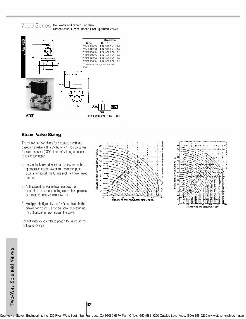
32Two-
Way
Sol
enoi
d Va
lves
The following flow charts for saturated steam arebased on a valve with a Cv factor = 1. To size valvesfor steam service (“SO” at end of catalog number),follow these steps:
1) Locate the known downstream pressure on theappropriate steam flow chart. From this pointdraw a horizontal line to intersect the known inletpressure.
2) At this point draw a vertical line down todetermine the corresponding steam flow (poundsper hour) for a valve with a Cv = 1.
3) Multiply this figure by the Cv factor listed in thecatalog for a particular steam valve to determinethe actual steam flow through the valve.
For hot water valves refer to page 115, Valve Sizingfor Liquid Service.
Hot Water and Steam Two-Way, Direct Acting, Direct Lift and Pilot Operated Valves
7000 Series
Steam Valve Sizing
#102
DRAW
INGS
Port Identification: P- IN/ - -OUT
DimensionValve H P C L
72228BN3TXXX 4.04 3.49 2.43 2.6472228BN4UXXX 4.04 3.49 2.43 2.6472228BN5VXXX 4.24 3.58 2.52 2.7272228RN3TXXX 4.04 3.49 2.43 2.6472228RN4UXXX 4.04 3.49 2.43 2.6472228RN5VXXX 4.04 3.58 2.52 2.72“X” denotes multiple digit combinations for brevity.
Courtesy of Steven Engineering, Inc.-230 Ryan Way, South San Francisco, CA 94080-6370-Main Office: (650) 588-9200-Outside Local Area: (800) 258-9200-www.stevenengineering.com

33 Two-
Way
Sol
enoi
d Va
lves
SKINNER 7000 Series High Pressure Two-Way Direct Acting and Pilot Operated Valves
Mechanical Characteristics
Standard Materials of Construction• Body– Brass or Stainless Steel (430F)• Seals– FKM, PCTFE, PTFE, NBR, Nylon,
Ruby as listed• Sleeve Tube– Stainless Steel (303 or 304)• Pilot Guide – Stainless Steel (303)• Pilot Orifice– Stainless Steel (303)• Piston– Stainless Steel (303)• Plunger– Stainless Steel (430FR)• Shading Ring– Copper• Stop– Stainless Steel (430FR)• Springs– Stainless Steel (18-8)
Compatible Fluids• All common media including air, inert gases,
hydraulic fluids, petroleum products, freons,water, steam and corrosive media. Use of non-lubricated gaseous media will substantially limitvalve life.
Electrical Characteristics
Voltages• DC– 12, 24• AC– 24/60, 110/50-120/60, 220/50-240/60,
(other AC/DC voltages available upon request)
Power Consumption• 10, 22 watts
Agency Approvals• UL and CSA approvals are available on valves
with applicable coil/enclosure combinations. Foradditional information see page 122.
Miscellaneous
Maximum Ambient Temperature• 10 watt AC/DC– 150°F• 22 watt AC/DC– 77°F• Fluxtron*/Magnelatch– 122°F
SPECIFICATIONS
DIRECT ACTING BRASS VALVES– NORMALLY CLOSED, PCTFE OR RUBY SEALSOperating Pressure Differential (PSI) MAX.**
Pipe Orifice Maximum Fluid Pressure Size Size Cv AC Ratings DC Ratings Temp. Vessel UL/CSA*** Const.NPT (inch) Factor Min.* 10 watt 22 watt 10 watt 22 watt (F) Number Approval Ref.
1/8” 1/16 0.11 0 1000 435 165 7121KBN1GF00 GP 973/32 0.24 0 500 725 175 320 210 7121KBN1LR00 GP 97
1/4” 1/16 0.11 0 1000 435 165 7121KBN2GF00 GP 971/16 0.11 0 1100 1450 435 800 210 7121KBN2GR00 GP 975/64 0.17 0 700 1030 260 460 210 7121KBN2JR00 GP 973/32 0.24 0 500 725 175 320 210 7121KBN2LR00 GP 971/8 0.31 0 365 525 125 220 210 7121KBN2NR00 GP 97
DIRECT ACTING STAINLESS STEEL VALVES–NORMALLY CLOSED, PCTFE, NYLON OR PTFE SEALS (Flange Seal-NBR)Operating Pressure Differential (PSI) MAX.**
Pipe Orifice Maximum Fluid Pressure Size Size Cv AC Ratings DC Ratings Temp. Vessel UL/CSA*** Const.NPT (inch) Factor Min.* 10 watt 22 watt 10 watt 22 watt (F) Number Approval Ref.
1/8” 3/64 0.062 0 1000 520 1000 165 71215SN1EF00 GP 1011/16 0.095 0 700 350 700 165 71215SN1GF00 GP 1011/32 0.021 0 3000 2500 3000 185 71216SN1BL00 - 1013/64 0.037 0 1500 1000 1500 185 71216SN1FU00 GP 1011/16 0.070 0 1250 500 1000 185 71216SN1GL00 GP 1015/64 0.090 0 500 200 400 185 71216SN1JT00 GP 101
1/4” 3/64 0.062 0 1000 520 1000 165 71215SN2EF00 GP 1011/16 0.095 0 700 350 700 165 71215SN2GF00 GP 1011/32 0.021 0 3000 2500 3000 185 71216SN2BL00 - 1013/64 0.037 0 1500 1000 1500 185 71216SN2FU00 GP 1011/16 0.070 0 1250 500 1000 185 71216SN2GL00 GP 1015/64 0.090 0 500 200 400 185 71216SN2JT00 GP 101
DIRECT ACTING BRASS VALVES– NORMALLY OPEN, PCTFE OR RUBY SEALSOperating Pressure Differential (PSI) MAX.**
Pipe Orifice Maximum Fluid Pressure Size Size Cv AC Ratings DC Ratings Temp. Vessel UL/CSA*** Const.NPT (inch) Factor Min.* 10 watt 22 watt 10 watt 22 watt (F) Number Approval Ref.
1/8” 1/16 0.11 0 435 435 165 7122KBN1GF00 GP 97
1/4” 1/16 0.11 0 435 435 165 7122KBN2GF00 GP 97
IN THIS SECTION : 7121, 7122, 7321, 7322
Courtesy of Steven Engineering, Inc.-230 Ryan Way, South San Francisco, CA 94080-6370-Main Office: (650) 588-9200-Outside Local Area: (800) 258-9200-www.stevenengineering.com

34Two-
Way
Sol
enoi
d Va
lves
* Pilot operated valves require the minimum pressure differential specified for proper valve operation.** Maximum fluid temperatures are provided for Class F coils. Valves with FKM seals (letter ‘V’ in 10th
position of pressure vessel number) can be used at fluid temperatures up to 250°F on DC and250°F on AC provided a Class H coil is used. Pressure ratings may be reduced, however. Consult factory for details.
*** UL/CSA Approval information: SS = Safety Shutoff GP = General Purpose Blank = Not ApprovedSee page 122 for additional agency approval information.
^ Rating suitable for all 22 watt integrated coils except DIN 300 coil. Consult Fluid Control Divisionfor application review.See page 120 for additional seal material combinations.
High Pressure Two-Way Direct Acting and Pilot Operated Valves
7000 Series
DIRECT ACTING STAINLESS STEEL VALVES–NORMALLY OPEN, PCTFE SEALSOperating Pressure Differential (PSI) MAX.**
Pipe Orifice Maximum Fluid Pressure Size Size Cv AC Ratings DC Ratings Temp. Vessel UL/CSA*** Const.NPT (inch) Factor Min.* 10 watt 22 watt 10 watt 22 watt (F) Number Approval Ref.
1/8” 3/64 0.054 0 750 750 165 71225SN1EF00 GP 1011/16 0.11 0 400 400 165 71225SN1GF00 GP 101
1/4” 3/64 0.054 0 750 750 165 71225SN2EF00 GP 1011/16 0.11 0 400 400 165 71225SN2GF00 GP 101
PILOT OPERATED BRASS VALVES–NORMALLY CLOSED, NBR, PTFE SEALS‘H’ Family valves listed are also available in FKM. ‘H’ Family valves contain ruby plunger seal.
Operating Pressure Differential (PSI) MAX.**Pipe Orifice Maximum Fluid Pressure Size Size Cv AC Ratings DC Ratings Temp. Vessel UL/CSA*** Const.NPT (inch) Factor Min.* 10 watt 22 watt 10 watt 22 watt (F) Number Approval Ref.
1/4” 1/4 0.76 5 1500 800 1500 210 73216BN2MT00 GP 105/16 2.5 5 600 435 600 185 7321HBN2SN00 GP 24
3/8” 7/16 3.5 5 600 435 600 185 7321HBN3TN00 GP 24
1/2” 9/16 4.1 5 600 435 600 185 7321HBN4UN00 GP 24
PILOT OPERATED STAINLESS STEEL VALVES–NORMALLY CLOSED, PTFE SEALSOperating Pressure Differential (PSI) MAX.**
Pipe Orifice Maximum Fluid Pressure Size Size Cv AC Ratings DC Ratings Temp. Vessel UL/CSA*** Const.NPT (inch) Factor Min.* 10 watt 22 watt 10 watt 22 watt (F) Number Approval Ref.
1/4” 1/4 0.76 5 1500 800 1500 210 73216SN2MT00 GP 17
PILOT OPERATED BRASS VALVES–NORMALLY OPEN, NBR SEALS Valves are also available in FKM. ‘H’ Family valves contain Ruby plunger seals.
Operating Pressure Differential (PSI) MAX.**Pipe Orifice Maximum Fluid Pressure Size Size Cv AC Ratings DC Ratings Temp. Vessel UL/CSA*** Const.NPT (inch) Factor Min.* 10 watt 22 watt 10 watt 22 watt (F) Number Approval Ref.
1/4” 5/16 2.5 5 600 600 185 7322HBN2SV00 GP 24
3/8” 7/16 3.5 5 600 600 185 7322HBN3TN00 GP 24
1/2” 9/16 4.1 5 600 600 185 7322HBN4UN00 GP 24
#97#101
DRAW
INGS DimensionValve H C
71215SN1XXXX 2.84 1.4871215SN2XXXX 2.84 1.4871216SN1XXXX 2.84 1.4871216SN2XXXX 2.84 1.4871225SN1XXXX 3.08 1.6871225SN2XXXX 3.08 1.68X” denotes multiple digit combinations for brevity.
NORMALLY OPENPort Identification: 1-OUT/ 2-IN
NORMALLY CLOSED NORMALLY OPENPort Identification: 1-IN/ 2-OUT
NORMALLY CLOSED
Courtesy of Steven Engineering, Inc.-230 Ryan Way, South San Francisco, CA 94080-6370-Main Office: (650) 588-9200-Outside Local Area: (800) 258-9200-www.stevenengineering.com

35 Two-
Way
Sol
enoi
d Va
lves
#24
High Pressure Two-Way Direct Acting and Pilot Operated Valves
7000 Series
Port Identification: 2- IN/ 1-OUT#17
Port Identification: P- IN/ A-OUT#10
NORMALLY CLOSED NORMALLY OPENPort Identification: Flow arrow
on body indicates flow direction–ports are not marked.
Courtesy of Steven Engineering, Inc.-230 Ryan Way, South San Francisco, CA 94080-6370-Main Office: (650) 588-9200-Outside Local Area: (800) 258-9200-www.stevenengineering.com

PILOT OPERATED BRASS VALVES–NORMALLY OPEN, NBR SEALSOperating Pressure Differential (PSI) MAX.
Pipe Orifice Maximum Fluid Pressure Size Size Cv AC Ratings DC Ratings Temp. Vessel UL/CSA*** Const.NPT (inch) Factor Min.* 10 watt 22 watt 10 watt 22 watt (F) Number Approval Ref.
3/4” 3/4 9.6 5 230 230 185 7322GBN53NC0 GP 109
1” 1 12.5 5 230 230 185 7322GBN64NC0 GP 109
1 1/4” 1 1/8 19.3 5 230 230 185 7322GBN76NC0 GP 109
1 1/2” 1 9/16 29.0 5 170 170 185 7322GBN88NC0 GP 109
2” 1 9/16 38.6 5 170 170 185 7322GBN99NC0 GP 109
PILOT OPERATED BRASS VALVES–NORMALLY CLOSED, NBR SEALSOperating Pressure Differential (PSI) MAX.
Pipe Orifice Maximum Fluid Pressure Size Size Cv AC Ratings DC Ratings Temp. Vessel UL/CSA*** Const.NPT (inch) Factor Min.* 10 watt 22 watt 10 watt 22 watt (F) Number Approval Ref.
3/8” 7/16 2.5 3 150 60 150 185 7321KBN3SNW0 SS 98
1/2” 7/16 2.5 3 150 60 150 185 7321KBN4SNW0 SS 98
3/4” 3/4 9.6 5 230 230 185 7321GBN53NMC GP 109
1” 1 12.5 5 230 230 185 7321GBN64NMC GP 109
1 1/4” 1 1/8 19.3 5 230 230 185 7321GBN76NMC GP 109
1 1/2” 1 9/16 29.0 5 230 200 230 185 7321GBN88NMC GP 109
2” 1 9/16 38.6 5 230 200 230 185 7321GBN99NMC GP 109
36Two-
Way
Sol
enoi
d Va
lves
SKINNER 7000 Series Anti -Water Hammer Two-Way Direct Lift and Pilot Operated Valves
Mechanical Characteristics
Standard Materials of Construction• Body–Brass• Seals–NBR• Sleeve Tube–Stainless Steel (303 or 304)• Plunger–Stainless Steel (430FR)• Shading Ring–Copper• Stop–Stainless Steel (430FR)• Springs–Stainless Steel (18-8)• Pilot Orifice–Stainless Steel (303)
Compatible Fluids• Water up to 185°F
Electrical Characteristics
Voltages• DC–12, 24• AC–24/60, 110/50-120/60, 220/50-240/60,
(other AC/DC voltages available upon request)
Power Consumption• 10, 22 watts
Agency Approvals• UL and CSA approvals are available on valves
with applicable coil/enclosure combinations. Foradditional information see page 122.
Miscellaneous
Maximum Ambient Temperature• 10 watt AC/DC–150°F• 22 watt AC/DC–77°F• Fluxtron*/Magnelatch–122°F
• Fluxtron coils not suitable for use on direct liftvalves.
SPECIFICATIONS
DIRECT LIFT BRASS VALVES–NORMALLY CLOSED, NBR SEALSOperating Pressure Differential (PSI) MAX.
Pipe Orifice Maximum Fluid Pressure Size Size Cv AC Ratings DC Ratings Temp. Vessel UL/CSA*** Const.NPT (inch) Factor Min.* 10 watt 22 watt 10 watt 22 watt (F) Number Approval Ref.
3/4” 19/32 5.5 0 230 100 185 7221GBN51NC0 SS 103
1” 19/32 5.5 0 230 100 185 7221GBN61NC0 SS 1031 11.7 0 230 85 185 7221GBN64NC0 SS 103
NOTE: Mechanical Options indicated in pressure vessel catalog number (eleventh and twelfth digits) are as follows:C0=four-step adjustable closing, MC=manual override with four-step adjustable closing, W0=non-adjustable control.
Courtesy of Steven Engineering, Inc.-230 Ryan Way, South San Francisco, CA 94080-6370-Main Office: (650) 588-9200-Outside Local Area: (800) 258-9200-www.stevenengineering.com

37 Two-
Way
Sol
enoi
d Va
lves
#109
* Direct Lift valves will open at zero differential pressure, however, full flow through the valve will notbe safely achieved. Pilot operated valves require the minimum pressure differential specified forproper valve operation.
***UL/CSA Approval Information: SS=Safety Shutoff GP=General Purpose Blank= Not ApprovedSee page 122 for additional agency information.
Anti -Water Hammer Two-Way Direct Lift and Pilot Operated Valves
7000 Series
Valve Type Opening ClosingTime Range Time Range(seconds) (seconds)
7221GBN51NC0 0.03 0.2-1.77221GBN61NC0 0.04-0.05 0.2-1.77221GBN64NC0 0.07-0.17 0.5-4.07321KBN3SNW0 0.015 0.857321KBN4SNW0 0.015 0.857321GBN53NMC 0.25-0.1 0.6-4.57321GBN64NMC 0.25-0.1 0.6-4.57321GBN76NMC 0.5-0.2 0.8-5.87321GBN88NMC 0.4-0.2 1.5-9.07321GBN99NMC 0.45-0.25 1.5-9.57322GBN53NC0 0.25-0.1 0.6-4.57322GBN64NC0 0.25-0.1 0.6-4.57322GBN76NC0 0.5-0.2 0.8-5.87322GBN88NC0 0.4-0.2 1.5-9.07322GBN99NC0 0.45-0.25 1.5-9.5
Resp
onse
Tim
eDR
AWIN
GS
#103
DRAW
INGS
#98
DimensionValve H P C L
7321KBN4SXXX 3.56 2.97 1.96 2.177321KBN2RXXX 3.56 2.97 1.96 1.977321KBN3SXXX 3.56 2.97 1.96 1.97“X” denotes multiple digit combinations for brevity.
DimensionValve H P C L W
7321GBN53XXX 4.75 3.86 2.84 3.94 2.757322GBN53XXX 4.75 3.86 2.84 3.94 2.757321GBN64XXX 4.75 3.86 2.84 3.94 2.757322GBN64XXX 4.75 3.86 2.84 3.94 2.757321GBN76XXX 5.41 4.11 3.09 4.33 2.757322GBN76XXX 5.41 4.11 3.09 4.33 2.757321GBN88XXX 5.66 4.37 3.35 5.51 3.907322GBN88XXX 5.66 4.37 3.35 5.51 3.907321GBN99XXX 6.25 4.60 3.58 5.91 3.907322GBN99XXX 6.25 4.60 3.58 5.91 3.90“X” denotes multiple digit combinations for brevity.
DimensionValve H P C L W
7221GBN51XXX 3.75 3.07 2.06 3.15 2.097221GBN61XXX 4.03 3.15 2.12 3.35 2.097221GBN64XXX 4.25 3.35 2.34 3.94 2.75“X” denotes multiple digit combinations for brevity.
NORMALLY OPENPort Identification: Flow arrow
on body indicates flow direction–ports are not marked.
Port Identification: Flow arrow on body indicates flow direction–
ports are not marked.
Port Identification: Flow arrow on body indicates flow direction–
ports are not marked.
NORMALLY CLOSED
Courtesy of Steven Engineering, Inc.-230 Ryan Way, South San Francisco, CA 94080-6370-Main Office: (650) 588-9200-Outside Local Area: (800) 258-9200-www.stevenengineering.com

38Two-
Way
Sol
enoi
d Va
lves
Dimension No-Voltage ElectricallyRelease Tripped
A 4.64 4.40B 4.31 4.07C 1.79 1.59D 3.26 3.06
PILOT OPERATED BRASS MANUAL RESET VALVES–NORMALLY OPEN, NBR SEALSOperating Pressure Differential (PSI) MAX. No-Voltage Electrically
Pipe Orifice Maximum Fluid Release TrippedSize Size Cv AC Ratings DC Ratings Temp. Pressure Pressure Const.NPT (inch) Factor Min.* 10 watt 22 watt 10 watt 22 watt (F) Vessel Vessel Ref.
3/4” 3/4 7.3 5 300 300 185 70222BN52NVR 70222BN52NET 25
1” 1 1/16 13.5 5 125 125 185 70228BN64NVR 70228BN64NET 25
1 1/4” 1 1/8 15.0 5 125 125 185 70228BN75NVR 70228BN75NET 25
1 1/2” 1 1/4 22.5 5 125 125 185 70228BN87NVR 70228BN87NET 25
SKINNER 7000 Series Manual Reset Two-Way Direct Acting and Pilot Operated Valves
Mechanical Characteristics
Standard Materials of Construction• Body–Brass or Stainless Steel (430)• Seals–NBR or FKM seals as listed• Sleeve Tube–Stainless Steel (303 or 304)• Plunger–Stainless Steel (430FR)• Shading Ring–Copper• Stop–Stainless Steel (430FR)• Springs–Stainless Steel (18-8)• Pilot Orifice–Stainless Steel (303)
Compatible Fluids• Depending on the valve used, most common
media including air, inert gases or petroleumproducts.
Electrical Characteristics
Voltages• DC–12, 24• AC–110/50-120/60, 220/50-240/60
Power Consumption• 10, 22 watts
Agency Approvals• cUL approval.
Miscellaneous
Maximum Ambient Temperature• 131°F
SPECIFICATIONS
* All wetted parts are stainless steel, FKM and plastic.
* Pilot operated valves require the minimum pressure differential specified for proper valve operation.
DIRECT ACTING STAINLESS STEEL MANUAL RESET VALVES–NORMALLY CLOSED, FKM SEALS*Operating Pressure Differential (PSI) MAX. No-Voltage Electrically
Pipe Orifice Maximum Fluid Release TrippedSize Size Cv AC Ratings DC Ratings Temp. Pressure Pressure Const.NPT (inch) Factor Min.* 10 watt 22 watt 10 watt 22 watt (F) Vessel Vessel Ref.
1/4” 3/32 0.18 0 150 150 185 70215SN2KVVR 70215SN2KVET 25
PILOT OPERATED BRASS MANUAL RESET VALVES–NORMALLY CLOSED, NBR SEALSOperating Pressure Differential (PSI) MAX. No-Voltage Electrically
Pipe Orifice Maximum Fluid Release TrippedSize Size Cv AC Ratings DC Ratings Temp. Pressure Pressure Const.NPT (inch) Factor Min.* 10 watt 22 watt 10 watt 22 watt (F) Vessel Vessel Ref.
1/2” 5/8 4.0 5 150 150 185 70218BN4UNVR 70218BN4UNET 25
3/4” 3/4 7.3 5 300 300 185 70212BN52NVR 70212BN52NET 25
1” 1 1/16 13.5 5 125 125 185 70218BN64NVR 70218BN64NET 25
1 1/4” 1 1/8 15.0 5 125 125 185 70218BN75NVR 70218BN75NET 25
1 1/2” 1 1/4 22.5 5 125 125 185 70218BN87NVR 70218BN87NET 25
#25
DRAW
INGS
Dimensions apply to Manual Reset feature only.
Courtesy of Steven Engineering, Inc.-230 Ryan Way, South San Francisco, CA 94080-6370-Main Office: (650) 588-9200-Outside Local Area: (800) 258-9200-www.stevenengineering.com

39 Two-
Way
Sol
enoi
d Va
lves
TWO-WAY REMOTE OPERATED VALVE PORT CONNECTIONSRemote Control Valve Hookup 3-Way Pilot Valve Hookup
Main Pilot InletValve Line IN Out Port* Normally Closed Normally Open CommonType Supply Port Port 1/8” NPT Port Port Port
Main Line PressureNormally Open 0-190 PSIG IN Out +10 PSI Minimum Pilot Exhaust
Common Pilot IN PortPort of 3- Main Line Pressure Vacuum (1/8” NPT) of Remote
Normally Open Vacuum Non-Vacuum Pump Vacuum Pump Way Pilot Valve + 10 PSI Minimum Control Valve
Main LinePressure + 10 PSI
Normally Closed 0-190 PSIG IN Out Pilot Exhaust Minimum
Main LinePressure + 10 PSI
Normally Closed Vacuum Non-Vacuum Pump Vacuum Pump Vacuum Minimum
SKINNER 7000 Series Remote Pressure Operated Two-Way Remote Operated Valves
Mechanical Characteristics
Standard Materials of Construction• Body–Brass• Seals–NBR• Springs–Stainless Steel (18-8)• Pilot Orifice–Stainless Steel (303)
Compatible Fluids• Lubricated Air, Non-Lubricated Air, Inert Gases,
Water, Hydraulic Fluids, Petroleum Products andadditional fluids compatible with materials ofconstruction.
Maximum Operating Pressure Differential• 190 PSI
Cv Factor• 2.4 to 11.0
Pipe Sizes• 3/8” TO 1” NPT
SPECIFICATIONS
* To assure long, trouble free life, the Pilot IN to main pressure differential should not exceed 200PSIG.
NOTE: This valve in it’s normal state, without piloting, is normally open.
#26
DRAW
INGS
REMOTE PRESSURE OPERATED VALVES–DUAL PURPOSEOrifice
Pipe Size Size Pressure Vessel Const.NPT (inch) Cv Factor Catalog Number Ref.
3/8” 1/2 2.4 75232BN3SN00 26
1/2” 1/2 2.8 75232BN4TN00 26
3/4” 3/4 7.3 75232BN52N00 26
1” 1 11.0 75232BN63N00 26
Dimension Port IdentificationValve H P C L W IN OUT
75232BN3SN00 3.17 2.35 1.51 2.75 1.97 IN OUT75232BN4TN00 3.17 2.35 1.51 2.75 1.97 IN OUT75232BN52N00 4.31 3.12 2.28 3.62 3.09 IN OUT75232BN63N00 4.73 3.40 2.56 4.31 3.45 P AValve can be normally closed or normally open, depending on piping of external pilot.
NORMALLY OPEN
Courtesy of Steven Engineering, Inc.-230 Ryan Way, South San Francisco, CA 94080-6370-Main Office: (650) 588-9200-Outside Local Area: (800) 258-9200-www.stevenengineering.com

DIRECT ACTING BRASS AND STAINLESS STEEL VALVES–NORMALLY CLOSEDBody Sleeve
Pipe Orifice Body Orifice Sleeve Maximum Operating Brass Stainless SteelSize Size Cv Size Cv Pressure Differential (PSI) Pressure Vessel Pressure VesselNPT (inch) Factor (inch) Factor 6 watt 3 watt* Catalog Number Catalog Number
1/8” 1/32 0.03 - - 800 775 3121BBN1AN00 3121BSN1AN003/64 0.05 - - 500 300 3121BBN1EN00 3121BSN1EN001/16 0.09 - - 300 95 3121BBN1GN00 3121BSN1GN005/64 0.13 - - 200 65 3121BBN1JN00 3121BSN1JN003/32 0.18 - - 175 40 3121BBN1LN00 3121BSN1LN001/8 0.24 - - 100 4 3121BBN1NN00 3121BSN1NN005/32 0.30 - - 50 - 3121BBN1QN00 3121BSN1QN00
* When ordering a pressure vessel with a 3 watt coil the seconddigit must be a 9. Example: 3921BBN1AN00 is a 2-way normallyclosed pressure vessel for use with 3 watt coils.
40Two-
Way
Sol
enoi
d Va
lves
Mechanical Characteristics
Standard Materials of Construction• Body–Brass or Stainless Steel (303)• Seals–NBR, FKM, Ethylene Propylene, CR• Sleeve Assembly–305 Stainless Steel (tube-
flange), 430F Stainless Steel (stop)• Plunger–430F Stainless Steel• Manifold Body–Aluminum• Flux Plate–Plated Steel• Housing–Plated Steel• Integrated Coil Encapsulant–Nylon• Springs _
Compatible Fluids• Air, inert gas, water, oilVacuum• Up to 5 microns depending on application
Electrical Characteristics
Voltages• DC 12, 24• AC–24/50-60, 110/50-120/60, 220/50-240/60
Power Consumption• 6 watts, 7.5 for 24/60• 3 watts
Agency Approvals• UL and CSA component recognition.
Miscellaneous
Maximum Ambient Temperature• 68°F for continuous duty cycle.
Response Time• 8 to 16 milliseconds to open or close.
Duty Cycle/Cycle Time• Continuous duty, 600 cycles per minute.
Weight• 8 oz.
Mounting• Two 8-32 tapped holes in bottom of valve body
supplied standard. A universal mounting bracketB19-006 is also available. See page 68 fordimensions.
SPECIFICATIONS
SKINNER 3000 Series Two-Way Direct Acting Valves
Performance Ratings Apply to All Voltages, Coil Constructions, Seal and Body Materials.
DIRECT ACTING BRASS AND STAINLESS STEEL VALVES–NORMALLY OPENBody Sleeve
Pipe Orifice Body Orifice Sleeve Maximum Operating Brass Stainless SteelSize Size Cv Size Cv Pressure Differential (PSI) Pressure Vessel Pressure VesselNPT (inch) Factor (inch) Factor 6 watt 3 watt* Catalog Number Catalog Number
1/8” - - 1/32 0.03 300 - 3129BBN1AN00 3129BSN1AN00- - 3/64 0.05 200 - 3129BBN1EN00 3129BSN1EN00- - 1/16 0.09 150 - 3129BBN1GN00 3129BSN1GN00- - 5/64 0.13 80 - 3129BBN1JN00 3129BSN1JN00- - 3/32 0.18 40 - 3129BBN1LN00 3129BSN1LN00
Courtesy of Steven Engineering, Inc.-230 Ryan Way, South San Francisco, CA 94080-6370-Main Office: (650) 588-9200-Outside Local Area: (800) 258-9200-www.stevenengineering.com

41 Two-
Way
Sol
enoi
d Va
lves
MANIFOLD ASSEMBLED VALVES–NORMALLY OPEN, COMMON INLET PRESSURE OVER SEATBody Sleeve
Orifice Body Orifice Sleeve Maximum Operating Cavity Screw-InSize Cv Size Cv Pressure Differential (PSI) Manifold Assembly Manifold Assembly**
(inch) Factor (inch) Factor 6 watt 3 watt Catalog Number Catalog Number
- - 3/64 0.05 200 - 3129BJA7ENC# 3129BSA6EN00- - 1/16 0.09 150 - 3129BJA7GNC# 3129BSA6GN00- - 3/32 0.09 40 - 3129BJA7LNC# 3129BSA6LN00
* When ordering a pressure vessel with a 3 watt coil the second digit must be a 9. Example:3921BSA6EN00 is a 2-way normally closed pressure vessel for use with 3 watt coils.Performance Ratings Apply to All Voltages, Coil Constructions, Seal and Body Materials.Screw-in body available in stainless steel only.
Note: Integrated coils not suitable for manifold mounting.
# Denotes the number of valves in the manifold, from 2 to 4.** Screw-in manifolds and valves sold separately.
Fitting V1-22-028 available to join manifolds when more than 4 stations required.
#27
DRAW
INGS
#28
Two-Way Direct Acting Valves
3000 Series
MANIFOLD ASSEMBLED VALVES–NORMALLY CLOSED, COMMON INLET PRESSURE OVER SEATBody Sleeve
Orifice Body Orifice Sleeve Maximum Operating Cavity Screw-InSize Cv Size Cv Pressure Differential (PSI) Manifold Assembly Manifold Assembly**
(inch) Factor (inch) Factor 6 watt 3 watt* Catalog Number Catalog Number
3/64 0.05 - - 500 300 3121BJA7ENC# 3121BSA6EN00
1/16 0.09 - - 300 95 3121BJA7GNC# 3121BSA6GN00
1/8 0.24 - - 100 4 - 3121BSA6NN00
5/32 0.30 - - 50 - - 3121BSA6QN00
Screw-In Common Pressure Number of StationsManifolds Port Direction 2 3 4
2WNC (3121) Inlet Over Seat 300-40-015 300-40-016 300-40-017
2 waynormallyclosed
2 waynormally
open
Courtesy of Steven Engineering, Inc.-230 Ryan Way, South San Francisco, CA 94080-6370-Main Office: (650) 588-9200-Outside Local Area: (800) 258-9200-www.stevenengineering.com

DIRECT ACTING STAINLESS STEEL VALVES–NORMALLY OPEN, FKM SEALSMax. Operating Pressure Class A Taped Coil
Pipe Orifice Cv Differential (PSI) Grommet Const.Size Diameter Factor AC DC Enclosure Ref.
1/8” NPT 1/32 0.019 400 400 B11DK1400 114
3/64 0.054 200 200 B11DK1200 114
3/32 0.13 40 40 B11DK1040 114
42Two-
Way
Sol
enoi
d Va
lves
Mechanical Characteristics
Standard Materials of Construction• Body–Stainless Steel (303)• Seals–NBR, FKM• Sleeve–304 Stainless Steel• Plunger–430F Stainless Steel• Stop–430 FR Stainless Steel• Springs–Stainless Steel (18-8)• Shading Ring–Copper (AC only)• Orifice 303 Stainless Steel
Compatible Fluids• Lubricated Air, non-Lubricated Air, Inert Gases,
Water, Steam, Hydraulic Fluids, PetroleumProducts, Freons, and additional fluidscompatible with materials of construction.
Note: Use with Steam and some Petroleum Productsnormally requires a plunger seal material modifi-cation. Consult Fluid Control Division to specify asuitable material.
Minimum Operating Pressure Differential• 0 PSI
Electrical Characteristics
Voltages• DC–12, 24• AC–24/60, 120/60, 240/60
Power Consumption• 7 watts
Miscellaneous
Vacuum• Down to 5 microns (0.005 torr, 2x10⁻⁴ in Hg)
Operating Speed• Up to 800 cycles per minute
Response Time• AC–Approximately 4-8 milliseconds to open or
close.• DC–Approximately 10-15 milliseconds to open,
6-12 milliseconds to close.
Accessories• Universal mounting bracket (B19-006)
• Wrench nut (B99-007)
SPECIFICATIONS
SKINNER B-Series General Purpose Two-WayDirect Acting Valves
DIRECT ACTING STAINLESS STEEL VALVES–NORMALLY CLOSED, NBR SEALS Max. Operating Pressure Class A Taped Coil
Pipe Orifice Cv Differential (PSI) Grommet Const.Size Diameter Factor AC DC Enclosure Ref..
1/8” NPT” 1/32 0.019 400 400 B2DA1400 1133/64 0.045 250 250 B2DA1250 1131/16 0.065 175 175 B2DA1175 1131/8 0.24 50 - B2DA1052 113
aaaaaaaaaaaaaaaaaa1/8 0.24 - 25 B2DA1026 113
DRAW
INGS
#113 #114Port Identification: 2- IN/ 1-OUTPort Identification: 2- IN/ 3*-OUT
(*not marked)
For Universal mounting Bracket Dimensions see page 68 .(3Way section)
Ordering B Series Valves:
Example:1) Specify the valve catalog number-B2DA12502) Specify the required voltage-120V, 60HzOR 3. See price book for coil codes
Courtesy of Steven Engineering, Inc.-230 Ryan Way, South San Francisco, CA 94080-6370-Main Office: (650) 588-9200-Outside Local Area: (800) 258-9200-www.stevenengineering.com

DIRECT ACTING BRASS STRAINER VALVE–NORMALLY CLOSEDDesigned to control water in commercial and industrial applications. Widely used in humidifying equipment, this valve offers the combination of filtering and fluid control in just one component for the protection of downstream instruments or machinery.
NPTPipe Orifice Cv Maximum Operating Pressure Const.Size Diameter Factor Differential (PSI) Part No. Ref.
1/8” 1/16 0.09 130 C2D420CF 32
43 Two-
Way
Sol
enoi
d Va
lves
Mechanical Characteristics
Standard Materials of Construction• Body–Brass (Stainless Steel available)• Seals–NBR, EPDM available• Sleeve–304 Stainless Steel• Plunger–430FR Stainless Steel• Stop–430 FR Stainless Steel• Springs–Stainless Steel (18-8)• Shading Ring–Copper (AC only)• Orifice–Brass, Stainless Steel
Compatible Fluids• Lubricated Air, Non-Lubricated Air, Inert Gases,
Water, Steam, Hydraulic Fluids, PetroleumProducts, Freons, and additional fluidscompatible with materials of construction. Note:Use with Steam may require plunger sealmaterial modification. Consult Fluid ControlDivision to specify a suitable material.
Minimum Operating Pressure Differential• 0 PSI
Pipe Sizes• 1/8” NPT dry seal.
Electrical Characteristics
Voltages• DC–12, 24, 120• AC–24/60, 120/60, 240/60 (other voltages
available upon request)
Power Consumption• 8 watts
Agency Approvals• UL and CSA approvals are generally available on
valves with applicable coil/enclosure combi-nations. For details consult Fluid ControlDivision.
Miscellaneous
Vacuum• Down to 5 microns (0.005 torr, 2x10⁻⁴ in Hg)
Operating Speed• Up to 600 cycles per minute
Response Time• AC–Approximately 4-8 milliseconds to open or
close.• DC–Approximately 10-15 milliseconds to open,
6-12 milliseconds to close.
Accessories• Universal mounting bracket (MECHB5)• Wrench nut
SPECIFICATIONS
SKINNER C-Series General Purpose Two-WayDirect Acting Valves
DIRECT ACTING BRASS VALVES–NORMALLY CLOSED, NBR SEALSMax. Operating Class A Taped Coil
NPT Pressure Differential Brass BodyPipe Orifice Cv (PSI) Grommet 1/2” NPT Const.Size Diameter Factor AC DC Enclosure Conduit Ref.
1/8” 1/16 0.10 275 - C2DA1277 C2DB1277 311/16 0.10 - 250 C2DA1251 C2DB1251 317/64 0.25 130 - C2DA1132 C2DB1132 317/64 0.25 - 80 C2DA1081 C2DB1081 311/8 0.31 90 - C2DA1092 C2DB1092 311/8 0.31 - 50 C2DA1051 C2DB1051 315/32 0.39 60 - C2DA1062 C2DB1062 315/32 0.39 - 30 C2DA1031 C2DB1031 31
#31
DRAW
INGS
Port Identification: 2- IN/ 1-OUT
Ordering C SeriesValves:
Example:1) Specify the valve catalognumber-C2DA10512) Specify the requiredvoltage-24 VDCOR 3. See price book for coilcodes
MECHB5:Mounting configurations.
Courtesy of Steven Engineering, Inc.-230 Ryan Way, South San Francisco, CA 94080-6370-Main Office: (650) 588-9200-Outside Local Area: (800) 258-9200-www.stevenengineering.com

44Two-
Way
Sol
enoi
d Va
lves
BRASS VALVE–NORMALLY CLOSED FOR HAZARDOUS LOCATIONS *M 7000 HAZARDOUS COLIL REQUIRED PAGEPipe Orifice Operating Pressure Max.Size Size Differential (PSI) Fluid Catalog Seal Constr.NPT (inch) Cv Factor Minimum* Maximum Temp. (F) Number Mat’l Ref.
1 1/2” 1 1/4 22.5 0 125 180 XLB27BB8127 NBR 34
Mechanical Characteristics
Standard Materials of Construction• Body–Brass• Seals–NBR, FKM as listed• Sleeve–Stainless Steel• Plunger–Stainless Steel• Stop–Stainless Steel• Springs–Stainless Steel• Shading Ring–Copper
Compatible Fluids• Lubricated Air, Non-Lubricated Air, Inert Gases,
Water, Hydraulic Fluids, Petroleum Products, andadditional fluids compatible with materials ofconstruction.
Electrical Characteristics
Voltages• AC–24/60, 110/50-120/60, 220/50-240/60
Power Consumption• 20 watts (Normal location)• 22 watts (Explosion-proof)
Agency Approvals• Valves are UL listed and CSA certified general
purpose for normal location. Explosion-proofvalves are UL listed and CSA certified forhazardous locations Class l groups C and D,Class ll groups E, F, and G.
Miscellaneous
Maximum Ambient Temperature• 77°F
BRASS VALVE–NORMALLY CLOSED FOR NORMAL LOCATIONS REPLACED BYPipe Orifice Operating Pressure Max.Size Size Differential (PSI) Fluid Catalog Seal Constr.NPT (inch) Cv Factor Minimum* Maximum Temp. (F) Number Mat’l Ref.
1 1/2” 1 1/4 22.5 0 125 180 LB27BB8127 NBR 33
SPECIFICATIONS
SKINNER LB27 Series Zero Delta P Two-Way Direct Lift Valves
* Valves will open at zero differential pressure, however full flow through the valve will not be achieved. If full flow is required at near zero differential, consult factory.• For Direct Lift valves with other process connection sizes please go to pg 20.
#33
DRAW
INGS
#34
DimensionPipe Size A B C D E F G H
1 1/2” 6.55 5.37 4.66 1.70 2.24 2.24 2.15 3.94
Ordering LB27Series Valves:
Example:1) Specify the valve catalog number-XLB27BB81272) Specify the required voltage-120/60-110/50
Courtesy of Steven Engineering, Inc.-230 Ryan Way, South San Francisco, CA 94080-6370-Main Office: (650) 588-9200-Outside Local Area: (800) 258-9200-www.stevenengineering.com

Three-Way Valve Contents
Skinner Three-Way Valve Specifications............ 46-72
Skinner 7000 Series Valves ............................ 46-63General Purpose Valves .......................... 46-57Quick Exhaust Valves .................................... 58High Pressure Valves .............................. 59-60Manual Reset Valves ................................ 61-62Remote Pressure Valves................................ 63
Skinner 3000 Series Valves ............................ 64-66Skinner B-Series Valves .................................. 67-68Skinner C-Series Valves .................................. 69-70Skinner A-Series Valves .................................. 71-72
Courtesy of Steven Engineering, Inc.-230 Ryan Way, South San Francisco, CA 94080-6370-Main Office: (650) 588-9200-Outside Local Area: (800) 258-9200-www.stevenengineering.com

46
Mechanical Characteristics
Standard Materials of Construction• Body–Brass or Stainless Steel (303 or 430F)• Seals–NBR, FKM, PCTFE as listed• Sleeve Tube–Stainless Steel (303 or 304)• Plunger–Stainless Steel (430FR)• Stop–Stainless Steel (430FR)• Springs–Stainless Steel (18-8)• Shading Ring–Copper• Pilot Orifice–Stainless Steel (303)
Compatible Fluids• Lubricated Air, Non-Lubricated Air, Inert Gases,
Water, Hydraulic Fluids, Petroleum Products andadditional fluids compatible with materials ofconstruction. Use of non-lubricated gaseousmedia will substantially limit valve life.
Electrical Characteristics
Voltages• DC–12, 24• AC–24/60, 110/50-120/60, 220/50-240/60,
(other AC/DC voltages available upon request)
Agency Approvals• UL and CSA approvals are available on valves
with applicable coil/enclosure combinations. Foradditional information see page 122.
Miscellaneous
Maximum Ambient Temperature• 10 watt AC/DC–150°F• 22 watt AC/DC–77°F• Fluxtron/Magnelatch–122°F
SPECIFICATIONS
SKINNER 7000 Series General Purpose Three-WayDirect Acting Valves
IN THIS SECTION : 7131, 7132, 7133, 7138
^ 2, 3 and 5 station subbases with 1/4” BSP common inlet port and 1/8” BSP outlet ports areavailable for use with D400 and D500 32mm DIN coils only. For details consult factory.
7131 DIRECT ACTING BRASS VALVES–NORMALLY CLOSED, PCTFE OR FKM SEALSOrifice Orifice Orifice Operating Pressure Differential (PSI) Max.*
Pipe Body Body Sleeve Cv Cv Maximum FluidSize NC NO Size Factor Factor AC Ratings DC Ratings Temp. Pressure Vessel UL/CSA** Const.NPT (inch) (inch) (inch) NC NO Min. 10 watt 22 watt 10 watt 22 watt (F) Catalog Number Approval Ref.
FLG^ 3/32 3/32 0.24 0.24 0 100 100 185 7131FBF4LV00 GP 36
1/8” 1/16 1/16 0.11 0.11 0 215 215 185 7131KBN1GV00 GP 373/32 3/32 0.24 0.24 0 100 100 185 7131KBN1LV00 GP 37
1/4” 1/32 1/32 0.02 0.02 0 580 580 165 7131KBN2BF00 GP 371/16 1/16 0.11 0.11 0 215 215 185 7131KBN2GV00 GP 375/64 3/32 0.17 0.24 0 150 150 185 7131KBN2JV00 GP 373/32 3/32 0.24 0.24 0 100 100 185 7131KBN2LV00 GP 375/64 1/8 0.17 0.31 0 150 150 185 7131TBN2JV00 GP 383/32 9/64 0.24 0.38 0 110 110 185 7131TBN2LV00 GP 383/16 1/4 0.49 0.63 0 30 30 185 7131TBN2RV00 GP 38
Thre
e-W
ay S
olen
oid
Valve
s
Courtesy of Steven Engineering, Inc.-230 Ryan Way, South San Francisco, CA 94080-6370-Main Office: (650) 588-9200-Outside Local Area: (800) 258-9200-www.stevenengineering.com

47
#39
DRAW
INGS
General Purpose Three-Way DirectActing Valves
7000 Series
7131 DIRECT ACTING STAINLESS STEEL VALVES–NORMALLY CLOSED, NBR OR FKM SEALS‘5’ Family valves also available with FKM seals.
Orifice Orifice Orifice Operating Pressure Differential (PSI) Max.*Pipe Body Body Sleeve Cv Cv Maximum FluidSize NC NO Size Factor Factor AC Ratings DC Ratings Temp. Pressure Vessel UL/CSA** Const.NPT (inch) (inch) (inch) NC NO Min. 10 watt 22 watt 10 watt 22 watt (F) Catalog Number Approval Ref.
1/8” 3/64 1/16 0.062 0.095 0 250 250 185 71315SN1EN00 GP 393/64 1/16 0.062 0.095 0 250 250 185 71315SN1ENJ1 GP 391/16 1/16 0.11 0.095 0 200 200 185 71315SN1GN00 GP 391/16 1/16 0.11 0.095 0 200 200 185 71315SN1GNJ1 GP 393/32 3/32 0.17 0.17 0 125 125 185 71315SN1KN00 GP 393/32 3/32 0.17 0.17 0 125 125 185 71315SN1KNJ1 GP 391/8 3/32 0.23 0.17 0 90 90 185 71315SN1MN00 GP 391/8 3/32 0.23 0.17 0 90 90 185 71315SN1MNJ1 GP 393/16 3/32 0.38 0.17 0 25 25 185 71315SN1SN00 GP 393/16 3/32 0.38 0.17 0 25 25 185 71315SN1SNJ1 GP 391/4 3/32 0.67 0.17 0 vac vac 185 71315SN1VNJ1 GP 39
1/4” 3/64 1/16 0.062 0.095 0 250 250 185 71315SN2EN00 GP 393/64 1/16 0.062 0.095 0 250 250 185 71315SN2ENJ1 GP 391/16 1/16 0.11 0.095 0 200 200 185 71315SN2GN00 GP 391/16 1/16 0.11 0.095 0 200 200 185 71315SN2GNJ1 GP 393/32 3/32 0.17 0.17 0 125 125 185 71315SN2KN00 GP 393/32 3/32 0.17 0.17 0 125 125 185 71315SN2KNJ1 GP 391/8 3/32 0.23 0.17 0 90 90 185 71315SN2MN00 GP 391/8 3/32 0.23 0.17 0 90 90 185 71315SN2MNJ1 GP 393/16 3/32 0.38 0.17 0 25 25 185 71315SN2SN00 GP 393/16 3/32 0.38 0.17 0 25 25 185 71315SN2SNJ1 GP 391/4 3/32 0.67 0.17 0 vac vac 185 71315SN2VNJ1 GP 391/16 1/16 0.095 0.095 0 200 200 185 7131TVN2GV00 GP 405/64 5/64 0.18 0.18 0 150 150 185 7131TVN2JV00 GP 403/32 3/32 0.19 0.19 0 110 110 185 7131TVN2LV00 GP 401/8 1/8 0.32 0.32 0 70 70 185 7131TVN2NV00 GP 40
Thre
e-W
ay S
olen
oid
Valve
s
* Maximum fluid temperatures are provided for Class F coils. Valves with FKM seals (letter ‘V’ in the10th position of pressure vessel number) can be used at fluid temperatures up to 240°F on DC and250°F on AC provided a Class H coil is used.
** UL/CSA Approval Information: GP=General Purpose Blank=Not ApprovedSee page 122 for additional agency approval information.
Port Identification:1-Pressure/ 2-Cylinder/ 3-Exhaust #40
Port Identification:1-Pressure/ 2-Cylinder/ 3-Exhaust
Courtesy of Steven Engineering, Inc.-230 Ryan Way, South San Francisco, CA 94080-6370-Main Office: (650) 588-9200-Outside Local Area: (800) 258-9200-www.stevenengineering.com

48
General Purpose Three-Way DirectActing Valves
7000 Series
#38
#37
Port Identification:1-Pressure/ 2-Cylinder/ 3-Exhaust
Port Identification:1-Cylinder/ 2-Pressure/ 0-Exhaust
Thre
e-W
ay S
olen
oid
Valve
s
#36Port Identification:
1-Cylinder/ 2-Pressure/ 0-Exhaust
Courtesy of Steven Engineering, Inc.-230 Ryan Way, South San Francisco, CA 94080-6370-Main Office: (650) 588-9200-Outside Local Area: (800) 258-9200-www.stevenengineering.com

49
General Purpose Three-Way DirectActing Valves
7000 Series
#118
DRAW
INGS
7132 DIRECT ACTING BRASS VALVES–NORMALLY OPEN, FKM SEALSOrifice Orifice Orifice Operating Pressure Differential (PSI) Max.*
Pipe Body Body Sleeve Cv Cv Maximum FluidSize NC NO Size Factor Factor AC Ratings DC Ratings Temp. Pressure Vessel UL/CSA** Const.NPT (inch) (inch) (inch) NC NO Min. 10 watt 22 watt 10 watt 22 watt (F) Catalog Number Approval Ref.
1/4” 5/32 1/8 0.31 0.41 0 150 185 7132TBN2NV00 GP 118
7139 DIRECT ACTING STAINLESS STEEL VALVES–NORMALLY OPEN, NBR SEALS‘5’ family valves also available with FKM seals.
Orifice Orifice Orifice Operating Pressure Differential (PSI) Max.*Pipe Body Body Sleeve Cv Cv Maximum FluidSize NC NO Size Factor Factor AC Ratings DC Ratings Temp. Pressure Vessel UL/CSA** Const.NPT (inch) (inch) (inch) NC NO Min. 10 watt 22 watt 10 watt 22 watt (F) Catalog Number Approval Ref.
1/8” 1/16 3/64 0.10 0.052 0 250 250 185 71395SN1ENJ1 GP 120
1/8 1/16 0.28 0.10 0 150 150 185 71395SN1GNJ1 GP 120
1/8 3/32 0.28 0.17 0 125 125 185 71395SN1KNJ1 GP 120
1/4” 1/16 3/64 0.10 0.052 0 250 250 185 71395SN2ENJ1 GP 120
1/8 1/16 0.28 0.10 0 150 150 185 71395SN2GNJ1 GP 120
1/8 3/32 0.28 0.17 0 125 125 185 71395SN2KNJ1 GP 120
#120Port Identification:
1-Exhaust/ 2-Cylinder/ 3-PressurePort Identification:
1-Exhaust/ 2-Cylinder/ 3-Pressure
* Maximum fluid temperatures are provided for Class F coils. Valves with FKM seals (letter ‘V’ in the10th position of pressure vessel number) can be used at fluid temperatures up to 250°F on DC and250°F on AC provided a Class H coil is used. Pressure ratings may be reduced, however. Consult
factory for details.** UL/CSA Approval Information: SS=Safety Shutoff SGP=General Purpose Blank=Not Approved
See page 122 for additional agency approval information.
Thre
e-W
ay S
olen
oid
Valve
s
Courtesy of Steven Engineering, Inc.-230 Ryan Way, South San Francisco, CA 94080-6370-Main Office: (650) 588-9200-Outside Local Area: (800) 258-9200-www.stevenengineering.com

50
General Purpose Three-Way DirectActing Valves
7000 Series
7133 DIRECT ACTING BRASS VALVES–MULTIPURPOSE, FKM SEALSOrifice Orifice Orifice Operating Pressure Differential (PSI) Max.*
Pipe Body Body Sleeve Cv Cv Maximum FluidSize NC NO Size Factor Factor AC Ratings DC Ratings Temp. Pressure Vessel UL/CSA** Const.NPT (inch) (inch) (inch) NC NO Min. 10 watt 22 watt 10 watt 22 watt (F) Catalog Number Approval Ref.
FLG^ 3/32 3/32 0.24 0.24 0 60 60 185 7133FBF4LVJ1 GP 114
1/8” 1/16 1/16 0.11 0.11 0 150 150 185 7133KBN1GVJ1 GP 116
5/64 5/64 0.15 0.15 0 100 100 185 7133KBN1JVJ1 GP 116
3/32 3/32 0.24 0.24 0 60 60 185 7133KBN1LVJ1 GP 116
1/4” 1/32 1/32 0.02 0.02 0 435 435 185 7133KBN2BVJ1 GP 116
1/16 1/16 0.10 0.10 0 150 150 185 7133KBN2GVJ1 GP 116
5/64 5/64 0.15 0.15 0 100 100 185 7133KBN2JVJ1 GP 116
3/32 3/32 0.24 0.24 0 60 60 185 7133KBN2LVJ1 GP 116
5/64 5/64 0.17 0.17 0 100 100 185 7133TBN2JV00 GP 119
3/32 3/32 0.19 0.19 0 60 60 185 7133TBN2LV00 GP 119
1/8 1/8 0.31 0.31 0 30 30 185 7133TBN2NV00 GP 119
#119
DRAW
INGS
#116#114Port Identification:
Pressure can be applied at either port.
Port Identification:Pressure can be applied at either port.
Port Identification:Pressure can be applied at either port.
* Maximum fluid temperatures are provided for Class F coils. Valves with FKM seals (letter ‘V’ in the10th position of pressure vessel number) can be used at fluid temperatures up to 240°F on DC and250°F on AC provided a Class H coil is used. Pressure ratings may be reduced, however. Consultfactory for details.
** UL/CSA Approval Information: SS=Safety Shutoff GP=General Purpose Blank=Not ApprovedSee page 122 for additional agency approval information.
^ 2, 3 and 5 station subbases with 1/4” BSP outlet ports and 1/8”BSP outlet ports are available for usewith D400 and D500 32mm DIN coils only. See page 98
Thre
e-W
ay S
olen
oid
Valve
s
Courtesy of Steven Engineering, Inc.-230 Ryan Way, South San Francisco, CA 94080-6370-Main Office: (650) 588-9200-Outside Local Area: (800) 258-9200-www.stevenengineering.com

51
#123
General Purpose Three-Way DirectActing Valves
7000 Series
7133 DIRECT ACTING STAINLESS STEEL VALVES–MULTIPURPOSE, NBR OR FKM SEALS‘5’ family valves also available with FKM seals.
Orifice Orifice Orifice Operating Pressure Differential (PSI) Max.*Pipe Body Body Sleeve Cv Cv Maximum FluidSize NC NO Size Factor Factor AC Ratings DC Ratings Temp. Pressure Vessel UL/CSA** Const.NPT (inch) (inch) (inch) NC NO Min. 10 watt 22 watt 10 watt 22 watt (F) Catalog Number Approval Ref.
1/8” 1/32 1/32 0.024 0.024 0 400 400 185 71335SN1ANJ1 GP 121
3/64 3/64 0.052 0.052 0 180 180 185 71335SN1ENJ1 GP 121
1/16 1/16 0.095 0.095 0 115 115 185 71335SN1GNJ1 GP 121
3/32 3/32 0.17 0.17 0 80 80 185 71335SN1KNJ1 GP 121
1/4” 1/32 1/32 0.024 0.024 0 400 400 185 71335SN2ANJ1 GP 121
3/64 3/64 0.052 0.052 0 180 180 185 71335SN2ENJ1 GP 121
1/16 1/16 0.095 0.095 0 115 115 185 71335SN2GNJ1 GP 121
3/32 3/32 0.17 0.17 0 80 80 185 71335SN2KNJ1 GP 121
1/16 1/16 0.095 0.095 0 150 150 185 7133TVN2GV00 GP 123
5/64 5/64 0.18 0.18 0 100 100 185 7133TVN2JV00 GP 123
3/32 3/32 0.19 0.19 0 60 60 185 7133TVN2LV00 GP 123
1/8 1/8 0.32 0.32 0 30 30 185 7133TVN2NV00 GP 123
#121
DRAW
INGS
1 = NC, 2 = Common, 3 = NO 1 = NC, 2 = Common, 3 = NO
Thre
e-W
ay S
olen
oid
Valve
s
Courtesy of Steven Engineering, Inc.-230 Ryan Way, South San Francisco, CA 94080-6370-Main Office: (650) 588-9200-Outside Local Area: (800) 258-9200-www.stevenengineering.com

52
General Purpose Three-Way DirectActing Valves
7000 Series
#122
DRAW
INGS
* Maximum fluid temperatures are provided for Class F coils. Valves with FKM seals (letter ‘V’ in the10th position of pressure vessel number) can be used at fluid temperatures up to 240°F on DC and250°F on AC provided a Class H coil is used.
** UL/CSA Approval Information: GP=General Purpose Blank=Not ApprovedSee page 122 for additional agency approval information.
7138 DIRECT ACTING STAINLESS STEEL VALVES–DIVERTING, NBR SEALS‘5’ family valves also available with FKM seals.
Orifice Orifice Orifice Operating Pressure Differential (PSI) Max.*Pipe Body Body Sleeve Cv Cv Maximum FluidSize NC NO Size Factor Factor AC Ratings DC Ratings Temp. Pressure Vessel UL/CSA** Const.NPT (inch) (inch) (inch) NC NO Min. 10 watt 22 watt 10 watt 22 watt (F) Catalog Number Approval Ref.
1/8” 1/16 1/16 0.095 0.095 0 235 235 185 71385SN1GNJ1 GP 122
3/32 3/32 0.17 0.17 0 140 140 185 71385SN1KNJ1 GP 122
1/8 3/32 0.23 0.17 0 125 125 185 71385SN1MNJ1 GP 122
1/4” 1/16 1/16 0.095 0.095 0 235 235 185 71385SN2GNJ1 GP 122
3/32 3/32 0.17 0.17 0 140 140 185 71385SN2KNJ1 GP 122
1/8 3/32 0.23 0.17 0 125 125 185 71385SN2MNJ1 GP 122
Port Identification:1-NC/ 2-IN/ 3-NO
Thre
e-W
ay S
olen
oid
Valve
s
Courtesy of Steven Engineering, Inc.-230 Ryan Way, South San Francisco, CA 94080-6370-Main Office: (650) 588-9200-Outside Local Area: (800) 258-9200-www.stevenengineering.com

53
#42
DRAW
INGS
#44
Mechanical Characteristics
Standard Materials of Construction• Body–Brass• Seals–NBR• Diaphragm Seal–NBR/PTFE• Sleeve Tube–Stainless Steel (304)• Plunger–Stainless Steel (430FR)• Stop–Stainless Steel (430FR)• Springs–Stainless Steel (18-8)• Shading Ring–Copper• Pilot Orifice–Stainless Steel (303)
Compatible Fluids• Lubricated Air, Non-Lubricated Air, Inert Gases,
Water, Hydraulic Fluids, Petroleum Products andadditional fluids compatible with materials ofconstruction. Use of non-lubricated gaseousmedia will substantially limit valve life.
Electrical Characteristics
Voltages• DC–12, 24• AC–24/60, 110/50-120/60, 220/50-240/60,
(other AC/DC voltages available upon request)
Agency Approvals• UL and CSA approvals are available on valves
with applicable coil/enclosure combinations. Foradditional information see page 122.
Miscellaneous
Maximum Ambient Temperature• 10 watt AC/DC–150°F• 22 watt AC/DC–77°F• Fluxtron/Magnelatch–122°F
SPECIFICATIONS
SKINNER 7000 Series General Purpose Three-WayPilot OperatedValves
IN THIS SECTION : 7331, 7332, 7338, 7433
7331 PILOT OPERATED BRASS VALVES–NORMALLY CLOSED, NBR SEALSOrifice Orifice Operating Pressure Differential (PSI) Max.
Pipe Body Body Cv Cv Maximum FluidSize NC NO Factor Factor AC Ratings DC Ratings Temp. Pressure Vessel UL/CSA** Const.NPT (inch) (inch) NC NO Min.* 10 watt 22 watt 10 watt 22 watt (F) Catalog Number Approval Ref.
3/8” 3/8 3/8 2.1 2.1 10 180 180 185 73312BN3RNJ0 GP 413/8 3/8 2.1 2.1 10 180 180 185 73312BN3RNJ1 GP 42
1/2” 1/2 1/2 3.6 3.6 10 180 180 185 73312BN4UNJ0 GP 411/2 1/2 3.6 3.6 10 180 180 185 73312BN4UNJ1 GP 42
3/4” 3/4 3/4 7.3 7.3 10 180 180 185 73312BN52NJ0 GP 433/4 3/4 7.3 7.3 10 180 180 185 73312BN52NJ1 GP 44
Port Identification:1-Pressure/ 2-Cylinder/ 3-Exhaust
Port Identification:1-Pressure/ 2-Cylinder/ 3-Exhaust
DimensionValve H P C L W S T R J K
73312BN3RNJ1 4.89 3.98 1.96 2.97 2.62 0.65 0.59 1.44 1.22 0.9173312BN4UNJ1 5.10 4.08 2.08 3.38 3.09 0.78 0.69 1.66 1.44 1.06
Thre
e-W
ay S
olen
oid
Valve
s
Courtesy of Steven Engineering, Inc.-230 Ryan Way, South San Francisco, CA 94080-6370-Main Office: (650) 588-9200-Outside Local Area: (800) 258-9200-www.stevenengineering.com

General Purpose Three-Way PilotOperatedValves
7000 Series
#41
DRAW
INGS
#43
54
Port Identification:1-Pressure/ 2-Cylinder/ 3-Exhaust
DimensionValve H P C L W T R J K
73312BN3RNJ0 5.34 4.41 1.96 2.97 2.62 0.59 1.44 1.22 0.9173312BN4UNJ0 5.62 4.56 2.08 3.38 3.09 0.69 1.66 1.41 1.06
Port Identification:1-Pressure/ 2-Cylinder/ 3-Exhaust
Thre
e-W
ay S
olen
oid
Valve
s
Courtesy of Steven Engineering, Inc.-230 Ryan Way, South San Francisco, CA 94080-6370-Main Office: (650) 588-9200-Outside Local Area: (800) 258-9200-www.stevenengineering.com

General Purpose Three-Way PilotOperatedValves
7000 Series
55
7332 PILOT OPERATED BRASS VALVES–NORMALLY OPEN, NBR SEALSOrifice Orifice Operating Pressure Differential (PSI) Max.
Pipe Body Body Cv Cv Maximum FluidSize NC NO Factor Factor AC Ratings DC Ratings Temp. Pressure Vessel UL/CSA** Const.NPT (inch) (inch) NC NO Min.* 10 watt 22 watt 10 watt 22 watt (F) Catalog Number Approval Ref.
3/8” 3/8 3/8 2.1 2.1 10 180 180 185 73322BN3RNJ0 GP 124
3/8 3/8 2.1 2.1 10 180 180 185 73322BN3RNJ1 GP 125
1/2” 1/2 1/2 3.6 3.6 10 180 180 185 73322BN4UNJ0 GP 124
1/2 1/2 3.6 3.6 10 180 180 185 73322BN4UNJ1 GP 125
3/4” 3/4 3/4 7.3 7.3 10 180 180 185 73322BN52NJ0 GP 128
3/4 3/4 7.3 7.3 10 180 180 185 73322BN52NJ1 GP 129
#125
DRAW
INGS
#129
DimensionValve H P C L W S T R J K
73322BN3RNJ1 4.89 3.98 1.96 2.97 2.62 0.65 0.59 1.44 1.22 0.9173322BN4UNJ1 5.10 4.08 2.08 3.38 3.09 0.78 0.69 1.66 1.44 1.06
Port Identification:1-Exhaust/ 2-Cylinder/ 3-Pressure
DimensionValve H P C L W T R J K
73322BN3RNJ0 5.34 4.41 1.96 2.97 2.62 0.59 1.44 1.22 0.9173322BN3UNJ0 5.62 4.56 2.08 3.38 3.09 0.69 1.66 1.41 1.06
Port Identification:1-Exhaust/ 2-Cylinder/ 3-Pressure
Port Identification:1-Exhaust/ 2-Cylinder/ 3-Pressure
Port Identification:1-Exhaust/ 2-Cylinder/ 3-Pressure
#124 #128
Thre
e-W
ay S
olen
oid
Valve
s
Courtesy of Steven Engineering, Inc.-230 Ryan Way, South San Francisco, CA 94080-6370-Main Office: (650) 588-9200-Outside Local Area: (800) 258-9200-www.stevenengineering.com

56
General Purpose Three-Way PilotOperatedValves
7000 Series
* Pilot operated valves require the minimum pressure differential specified for proper valve operation.** UL/CSA Approval Information: GP=General Purpose Blank=Not Approved
See page 122 for additional agency approval information.
7338 PILOT OPERATED BRASS VALVES–DIVERTING, NBR SEALSOrifice Orifice Operating Pressure Differential (PSI) Max.
Pipe Body Body Cv Cv Maximum FluidSize NC NO Factor Factor AC Ratings DC Ratings Temp. Pressure Vessel UL/CSA** Const.NPT (inch) (inch) NC NO Min.* 10 watt 22 watt 10 watt 22 watt (F) Catalog Number Approval Ref.
3/8” 3/8 3/8 2.1 2.1 10 180 180 185 73382BN3RNJ1 GP 126
1/2” 1/2 1/2 3.6 3.6 10 180 180 185 73382BN4UNJ1 GP 126
3/4” 3/4 3/4 7.3 7.3 10 180 180 185 73382BN52NJ1 GP 130
#126
DRAW
INGS
Port Identification:1-NC/ 2-IN/ 3-NO
DimensionValve H P C L W S T R J K
73382BN3RNJ1 4.89 3.98 1.96 2.97 2.62 0.65 0.59 1.44 1.22 0.9173382BN4UNJ1 5.10 4.08 2.08 3.38 3.09 0.78 0.69 1.66 1.44 1.06
Port Identification:1-NC/ 2-IN/ 3-NO#130
Thre
e-W
ay S
olen
oid
Valve
s
Courtesy of Steven Engineering, Inc.-230 Ryan Way, South San Francisco, CA 94080-6370-Main Office: (650) 588-9200-Outside Local Area: (800) 258-9200-www.stevenengineering.com

57
General Purpose Three-Way PilotOperatedValves
7000 Series
External Pilot Pressure ValvesWhen an application requires the separation of thefluid in the main line from the pilot operator, it isnecessary to control the pilot externally. Examplesinclude:
• Controlling contaminated fluids up to 170 PSI.• Controlling pressures below the minimum
operating pressure of 10 PSI.• Operating valves on vacuum.
For such applications, the following 3-waymultipurpose valves are provided with connectionsfor external pressure to operate the pilot. Theminimum external pilot pressure required is themain line pressure plus 10 PSI. The maximum
external pilot pressure is 180 PSI for pressureapplications, and 165 PSI for vacuum applications.
For vacuum service the vacuum line must beconnected to the normally open port, and pilotpressure must be connected to the normally closedpilot port.
* UL/CSA Approval Information: GP=General Purpose Blank=Not ApprovedSee page 122 for additional agency approval information.
7433 PILOT OPERATED BRASS VALVES (EXTERNAL PILOT PRESSURE)– MULTIPURPOSE, NBR SEALSOrifice Orifice Operating Pressure Differential (PSI) Max.
Pipe Body Body Cv Cv Maximum FluidSize NC NO Factor Factor AC Ratings DC Ratings Temp. Pressure Vessel UL/CSA* Const.NPT (inch) (inch) NC NO Min. 10 watt 22 watt 10 watt 22 watt (F) Catalog Number Approval Ref.
3/8” 3/8 3/8 2.1 2.1 0 170 170 185 74332BN3RNJ1 GP 127
1/2” 1/2 1/2 3.6 3.6 0 170 170 185 74332BN4UNJ1 GP 127
3/4” 3/4 3/4 7.3 7.3 0 170 170 185 74332BN52NJ1 GP 131
#127
DRAW
INGS
#131Port Identification:
Pressure can be applied at either port.
DimensionValve H P C L W S T R J K
74332BN3RNJ1 4.72 3.79 1.96 2.97 2.62 0.65 0.59 1.44 1.22 0.9174332BN4UNJ1 4.93 3.91 2.08 3.38 3.09 0.78 0.69 1.66 1.44 1.06
Port Identification:Pressure can be applied at either port.
Thre
e-W
ay S
olen
oid
Valve
s
Courtesy of Steven Engineering, Inc.-230 Ryan Way, South San Francisco, CA 94080-6370-Main Office: (650) 588-9200-Outside Local Area: (800) 258-9200-www.stevenengineering.com

58
SKINNER 7000 Series Quick Exhaust Three-WayDirect Acting Valves
Mechanical Characteristics
Standard Materials of Construction• Body–Stainless Steel (430F), Brass• Seals–NBR• Sleeve Tube–Stainless Steel (303 or 304)• Plunger–Stainless Steel (430FR)• Stop–Stainless Steel (430FR)• Springs–Stainless Steel (18-8 or 17-7PH)• Shading Ring –Copper• Pilot Orifice–Stainless Steel (303)
Compatible Fluids• Lubricated Air, Non-Lubricated Air, Inert
Gases,Water, Hydraulic Fluids, PetroleumProducts and additional fluids compatible withmaterials of construction. Use of non-lubricatedgaseous media will substantially limit valve life.
Electrical Characteristics
Voltages• DC–12, 24• AC–24/60, 110/50-120/60, 220/50-240/60,
(other AC/DC voltages available upon request)
Agency Approvals• UL and CSA approvals are available on valves
with applicable coil/enclosure combinations. Foradditional information see page 122.
Miscellaneous
Maximum Ambient Temperature• 10 watt AC/DC–150°F• 22 watt AC/DC–77°F• Fluxtron/Magnelatch–122°F
SPECIFICATIONS
#46
DRAW
INGS
#45
DIRECT ACTING BRASS VALVES–NORMALLY CLOSED, NBR SEALSOrifice Orifice Orifice Operating Pressure Differential (PSI) Max.
Pipe Body Body Sleeve Cv Cv Maximum FluidSize NC NO Size Factor Factor AC Ratings DC Ratings Temp. Pressure Vessel UL/CSA** Const.NPT (inch) (inch) (inch) NC NO Min.* 10 watt 22 watt 10 watt 22 watt (F) Catalog Number Approval Ref.
1/4” 3/32 1/4 3/32 0.2 1.1 0 100 100 185 7131EBN2LN00 GP 45
DIRECT ACTING STAINLESS STEEL VALVES–NORMALLY CLOSED, NBR SEALSOrifice Orifice Orifice Operating Pressure Differential (PSI) Max.
Pipe Body Body Sleeve Cv Cv Maximum FluidSize NC NO Size Factor Factor AC Ratings DC Ratings Temp. Pressure Vessel UL/CSA** Const.NPT (inch) (inch) (inch) NC NO Min.* 10 watt 22 watt 10 watt 22 watt (F) Catalog Number Approval Ref.
1/4” 3/64 1/8 3/32 0.052 0.35 0 250 250 185 71313SN2EN00 GP 46
3/64 1/8 3/32 0.052 0.35 0 250 250 185 71313SN2ENJ1 GP 46
1/16 1/8 3/32 0.09 0.35 0 200 200 185 71313SN2GN00 GP 46
1/16 1/8 3/32 0.09 0.35 0 200 200 185 71313SN2GNJ1 GP 46
3/32 1/8 3/32 0.11 0.35 0 125 125 185 71313SN2KN00 GP 46
3/32 1/8 3/32 0.11 0.35 0 125 125 185 71313SN2KNJ1 GP 46
1/8 1/8 3/32 0.13 0.35 0 90 90 185 71313SN2MN00 GP 46
1/8 1/8 3/32 0.13 0.35 0 90 90 185 71313SN2MNJ1 GP 46
* The valves operate at 0 PSI, however a 2 PSI minimum pressure differential is required to actuate thepressure operated quick exhaust poppet.
** UL/CSA Approval Information: GP=General Purpose Blank=Not ApprovedSee page 122 for additional agency approval information.
Port Identification:1-Pressure/ 2-Cylinder/ 3-Exhaust
Port Identification:1-Pressure/ 2-Cylinder/ 3-Exhaust
Thre
e-W
ay S
olen
oid
Valve
s
Courtesy of Steven Engineering, Inc.-230 Ryan Way, South San Francisco, CA 94080-6370-Main Office: (650) 588-9200-Outside Local Area: (800) 258-9200-www.stevenengineering.com

59
Thre
e-W
ay S
olen
oid
Valve
s
DIRECT ACTING STAINLESS STEEL VALVES–MULTIPURPOSE, NBR SEALSOrifice Orifice Operating Pressure Differential (PSI) Max.*
Pipe Body Body Cv Cv Maximum FluidSize NC NO Factor Factor AC Ratings DC Ratings Temp. Pressure Vessel UL/CSA** Const.NPT (inch) (inch) NC NO Min. 10 watt 22 watt 10 watt 22 watt (F) Catalog Number Approval Ref.
1/8” 1/32 1/32 0.024 0.024 0 400 400 185 71335SN1ANJ1 GP 121
1/4” 1/32 1/32 0.024 0.024 0 400 400 185 71335SN2ANJ1 GP 121
DIRECT ACTING BRASS VALVES–MULTIPURPOSE, FKM SEALSOrifice Orifice Operating Pressure Differential (PSI) Max.*
Pipe Body Body Cv Cv Maximum FluidSize NC NO Factor Factor AC Ratings DC Ratings Temp. Pressure Vessel UL/CSA** Const.NPT (inch) (inch) NC NO Min. 10 watt 22 watt 10 watt 22 watt (F) Catalog Number Approval Ref.
1/4” 1/32 1/32 0.02 0.02 0 435 435 185 7133KBN2BVJ1 GP 117
Mechanical Characteristics
Standard Materials of Construction• Body–Brass, Stainless Steel (430F)• Seals FKM, PCTFE, NBR, Ruby as listed• Sleeve Tube–Stainless Steel (304)• Plunger–Stainless Steel (430FR)• Stop–Stainless Steel (430FR)• Springs–Stainless Steel (18-8)• Shading Ring–Copper• Pilot Orifice–Stainless Steel (303)
Compatible Fluids• All common media including air, inert gases,
hydraulic fluids, petroleum products, andwater.Use of non-lubricated gaseous media willsubstantially limit valve life.
Electrical Characteristics
Voltages• DC–12, 24• AC–24/60, 110/50-120/60, 220/50-240/60,
(other AC/DC voltages available upon request)
Agency Approvals• UL and CSA approvals are available on valves
with applicable coil/enclosure combinations. Foradditional information see page 122.
Miscellaneous
Maximum Ambient Temperature• 10 watt AC/DC–150°F• 22 watt AC/DC–77°F• Fluxtron/Magnelatch–122°F
SPECIFICATIONS
SKINNER 7000 Series High Pressure Three-Way DirectActing Valves
* Maximum fluid temperatures are provided for Class F coils. Valves with Ruby or FKM seals (letter ‘R’or ‘V’ in 10th position of pressure vessel number) can be used at fluid temperatures up to 240°F onDC and 250°F on AC provided a Class H coil is used.
** UL/CSA Approval Information: GP=General Purpose Blank=Not ApprovedSee page 122 for additional agency approval information.
DIRECT ACTING BRASS VALVES–NORMALLY CLOSED, PCTFE OR RUBY SEALSOrifice Orifice Operating Pressure Differential (PSI) Max.*
Pipe Body Body Cv Cv Maximum FluidSize NC NO Factor Factor AC Ratings DC Ratings Temp. Pressure Vessel UL/CSA** Const.NPT (inch) (inch) NC NO Min. 10 watt 22 watt 10 watt 22 watt (F) Catalog Number Approval Ref.
1/4” 1/32 1/32 0.02 0.02 0 580 580 165 7131KBN2BF00 GP 117
1/32 1/32 0.02 0.02 0 1100 1100 210 7131KBN2BR00 GP 117
3/64 1/16 0.055 0.11 0 435 435 210 7131KBN2ER00 GP 117
Courtesy of Steven Engineering, Inc.-230 Ryan Way, South San Francisco, CA 94080-6370-Main Office: (650) 588-9200-Outside Local Area: (800) 258-9200-www.stevenengineering.com

60
High Pressure Three-Way DirectActing Valves
7000 Series
#117#121
DRAW
INGS
NORMALLY CLOSEDPort Identification:
1-Cylinder/ 2-Pressure/ 0-Exhaust
MULTIPURPOSEPort Identification:
Pressure can be applied at either port.Port Identification:
Pressure can be applied at either port.
Thre
e-W
ay S
olen
oid
Valve
s
Courtesy of Steven Engineering, Inc.-230 Ryan Way, South San Francisco, CA 94080-6370-Main Office: (650) 588-9200-Outside Local Area: (800) 258-9200-www.stevenengineering.com

61
Thre
e-W
ay S
olen
oid
Valve
s
DIRECT ACTING BRASS VALVES–UNIVERSAL ALL-PORTS-IN-BODY, FKM SEALSOperating Pressure Differential (PSI)
Pipe Orifice Maximum No-Voltage Release Electrically TrippedSize Size Cv AC Ratings DC Ratings Pressure Vessel Pressure Vessel Const.NPT (inch) Factor Min.* 10 watt 22 watt 10 watt 22 watt Number Number Ref.
1/4” 5/64 x 5/64 0.14 x 0.14 0 100 100 7033TBN2JVVR 7033TBN2JVET 25
1/4” 1/8 x 1/8 0.23 x 0.23 0 50 50 7033TBN2NVVR 7033TBN2NVET 25
Mechanical Characteristics
Standard Materials of Construction• Body–Brass or Stainless Steel (430)• Seals–NBR or FKM seals as listed• Sleeve Tube–Stainless Steel (303 or 304)• Plunger–Stainless Steel (430FR)• Shading Ring–Copper• Stop–Stainless Steel (430FR)• Springs–Stainless Steel (18-8)• Pilot Orifice–Stainless Steel (303)
Compatible Fluids• Depending on the valve used, most common
media including air, inert gases or petroleumproducts.
Electrical Characteristics
Voltages• DC–12, 24• AC–110/50-120/60, 220/50-240/60
Power Consumption• 10, 22 watts
Agency Approvals• cUL approval.
Miscellaneous
Maximum Ambient Temperature• 131°F
SPECIFICATIONS
SKINNER 7000 Series Manual Reset Three-Way Direct Acting and Pilot Operated Valves
* Pilot operated valves require the minimum pressure differential specified for proper valve operation.
PILOT OPERATED BRASS VALVES–NORMALLY OPEN, NBR SEALSOperating Pressure Differential (PSI)
Pipe Orifice Maximum No-Voltage Release Electrically TrippedSize Size Cv AC Ratings DC Ratings Pressure Vessel Pressure Vessel Const.NPT (inch) Factor Min.* 10 watt 22 watt 10 watt 22 watt Number Number Ref.
3/8” 5/8 2.1 10 180 180 70322BN3RNVR 70322BN3RNET 25
1/2” 1/2 3.6 10 180 180 70322BN4UNVR 70322BN4UNET 25
3/4” 3/4 7.3 10 180 180 70322BN52NVR 70322BN52NET 25
DIRECT ACTING STAINLESS STEEL VALVES–NORMALLY OPEN, NBR SEALSOperating Pressure Differential (PSI)
Pipe Orifice Maximum No-Voltage Release Electrically TrippedSize Size Cv AC Ratings DC Ratings Pressure Vessel Pressure Vessel Const.NPT (inch) Factor Min.* 10 watt 22 watt 10 watt 22 watt Number Number Ref.
1/4” 1/16 x 3/32 0.095 x 0.17 0 150 150 70325SN2GNVR 70325SN2GNET 25
PILOT OPERATED BRASS VALVES–NORMALLY CLOSED, NBR SEALSOperating Pressure Differential (PSI)
Pipe Orifice Maximum No-Voltage Release Electrically TrippedSize Size Cv AC Ratings DC Ratings Pressure Vessel Pressure Vessel Const.NPT (inch) Factor Min.* 10 watt 22 watt 10 watt 22 watt Number Number Ref.
3/8” 3/8 2.1 10 180 180 70312BN3RNVR 70312BN3RNET 25
1/2” 1/2 3.6 10 180 180 70312BN4UNVR 70312BN4UNET 25
3/4” 3/4 7.3 10 180 180 70312BN52NVR 70312BN52NET 25
DIRECT ACTING STAINLESS STEEL VALVES–NORMALLY CLOSED, NBR OR FKM SEALSOperating Pressure Differential (PSI)
Pipe Orifice Maximum No-Voltage Release Electrically TrippedSize Size Cv AC Ratings DC Ratings Pressure Vessel Pressure Vessel Const.NPT (inch) Factor Min.* 10 watt 22 watt 10 watt 22 watt Number Number Ref.
1/4” 3/64 x 3/32 0.062 x 0.17 0 200 200 70315SN2ENVR 70315SN2ENET 251/16 x 3/32 0.11 x 0.17 0 150 150 70315SN2GVVR 70315SN2GVET 253/32 x 3/32 0.17 x 0.17 0 90 90 70315SN2KVVR 70315SN2KVET 251/8 x 3/32 0.23 x 0.17 0 60 60 70315SN2MNVR 70315SN2MNET 25
Courtesy of Steven Engineering, Inc.-230 Ryan Way, South San Francisco, CA 94080-6370-Main Office: (650) 588-9200-Outside Local Area: (800) 258-9200-www.stevenengineering.com
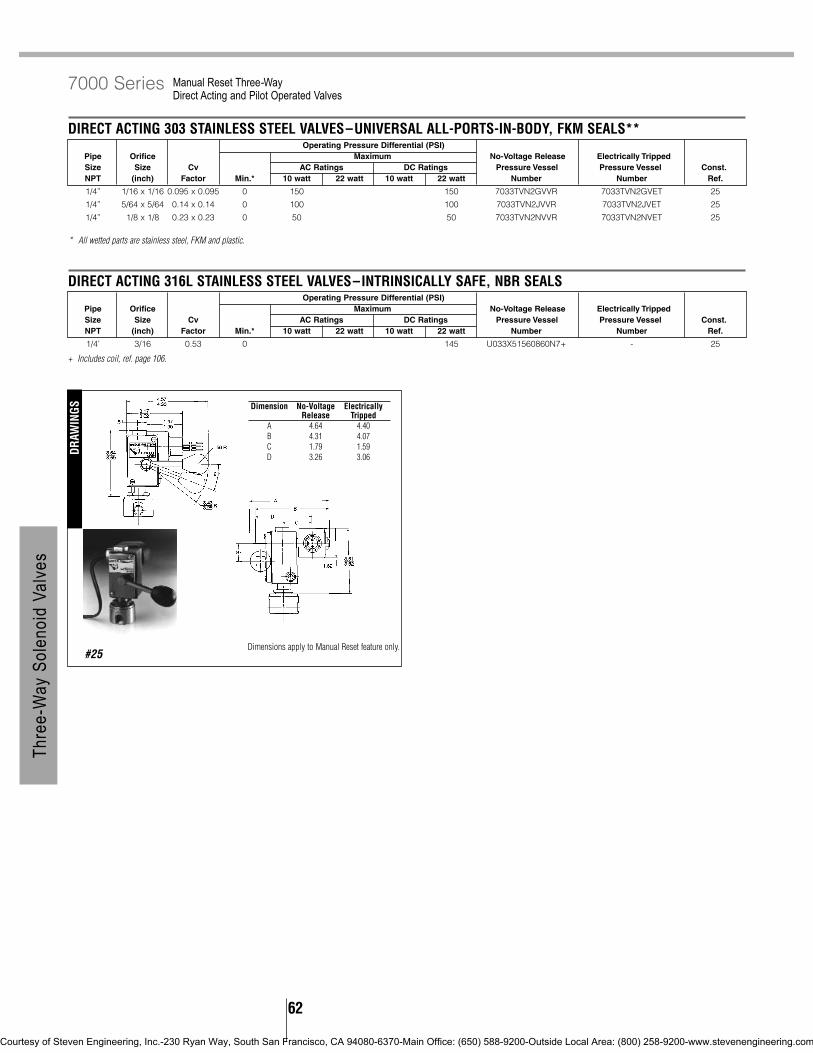
62
+ Includes coil, ref. page 106.
* All wetted parts are stainless steel, FKM and plastic.
Manual Reset Three-Way Direct Acting and Pilot Operated Valves
7000 Series
DIRECT ACTING 303 STAINLESS STEEL VALVES–UNIVERSAL ALL-PORTS-IN-BODY, FKM SEALS**Operating Pressure Differential (PSI)
Pipe Orifice Maximum No-Voltage Release Electrically TrippedSize Size Cv AC Ratings DC Ratings Pressure Vessel Pressure Vessel Const.NPT (inch) Factor Min.* 10 watt 22 watt 10 watt 22 watt Number Number Ref.
1/4” 1/16 x 1/16 0.095 x 0.095 0 150 150 7033TVN2GVVR 7033TVN2GVET 25
1/4” 5/64 x 5/64 0.14 x 0.14 0 100 100 7033TVN2JVVR 7033TVN2JVET 25
1/4” 1/8 x 1/8 0.23 x 0.23 0 50 50 7033TVN2NVVR 7033TVN2NVET 25
DIRECT ACTING 316L STAINLESS STEEL VALVES–INTRINSICALLY SAFE, NBR SEALSOperating Pressure Differential (PSI)
Pipe Orifice Maximum No-Voltage Release Electrically TrippedSize Size Cv AC Ratings DC Ratings Pressure Vessel Pressure Vessel Const.NPT (inch) Factor Min.* 10 watt 22 watt 10 watt 22 watt Number Number Ref.
1/4’ 3/16 0.53 0 145 U033X51560860N7+ - 25
#25
DRAW
INGS Dimension No-Voltage Electrically
Release TrippedA 4.64 4.40B 4.31 4.07C 1.79 1.59D 3.26 3.06
Thre
e-W
ay S
olen
oid
Valve
s
Dimensions apply to Manual Reset feature only.
Courtesy of Steven Engineering, Inc.-230 Ryan Way, South San Francisco, CA 94080-6370-Main Office: (650) 588-9200-Outside Local Area: (800) 258-9200-www.stevenengineering.com

63
Thre
e-W
ay S
olen
oid
Valve
s
Mechanical Characteristics
Standard Materials of Construction• Body–Brass• Diaphragm Seal–NBR/PTFE• Seals–NBR• Springs–Stainless Steel (18-8)• Pilot Orifice–Stainless Steel (303)
Compatible Fluids• Lubricated Air, Non-Lubricated Air, Inert Gases,
Water, Hydraulic Fluids, Petroleum Products andadditional fluids compatible with materials ofconstruction.
SPECIFICATIONS
SKINNER 7000 Series Remote Pressure Operated Three-Way Remote Operated Valves
Note that these valves do not feature an electrical operator, therefore no enclosure and coil selection is necessary.
* To assure long, trouble free life, the Pilot IN to main pressure should not exceed 200 PSIG.
#47
DRAW
INGS
#48
REMOTE OPERATED VALVE PORT CONNECTIONSConnections For Remote Valve 3-Way Pilot Valve Hookup
Main Normally Normally Pilot Inlet Normally NormallyValve Type Line Supply Closed Port Open Port Common Port Port* Closed Port Open Port Common Port
1/8” NPT
Media Connect to Main Line Pressure Pilot 1/8” NPTNormally 0-180 PSIG Exhaust Media Inlet Cylinder Common +10 PSI Minimum Exhaust Pilot
Open Vacuum Atmosphere Vacuum Cylinder Port of 3-Way 10 PSI Minimum Vacuum of Remote
Pilot Main Line Pressure Pilot ControlNormally 0-180 PSIG Media Inlet Media Exhaust Cylinder +10 PSI Minimum Exhaust ValveClosed Vacuum Vacuum Atmosphere Cylinder 10 PSI Minimum Vacuum
Main Line Pressure PilotDirectional 0-180 PSIG Media Outlet Media Outlet Media Inlet +10 PSI Minimum Exhaust
Control Vacuum Inlet Inlet Vacuum 10 PSIG Minimum Vacuum
REMOTE PRESSURE OPERATED VALVES–DUAL PURPOSEPipe Orifice Body Orifice Body Cv CvSize NC NO Factor Factor Pressure Vessel Const.NPT (inch) (inch) NC NO Catalog Number Ref.
3/8” 3/8 3/8 2.1 2.1 75332BN3RN00 47
1/2” 1/2 1/2 3.6 3.6 75332BN4UN00 47
3/4” 3/4 3/4 7.3 7.3 75332BN52N00 48
Port Identification:Pressure can be applied at any port.
DimensionValve H P L W S T R J K
75332BN3RN00 2.43 1.49 2.97 2.62 0.65 0.59 1.44 1.22 0.9175332BN4UN00 2.67 1.61 3.38 3.09 0.78 0.69 1.66 1.41 1.06
Port Identification:Pressure can be applied at any port.
Courtesy of Steven Engineering, Inc.-230 Ryan Way, South San Francisco, CA 94080-6370-Main Office: (650) 588-9200-Outside Local Area: (800) 258-9200-www.stevenengineering.com

64
Mechanical Characteristics
Standard Materials of Construction• Body–Brass or Stainless Steel (303)• Seals–NBR, FKM, Ethylene Propylene, CR• Sleeve Assembly–305 Stainless Steel (tube-
flange), 430F Stainless Steel (stop)• Plunger–430F Stainless Steel• Manifold Body–Aluminum• Flux Plate–Plated Steel• Housing–Plated Steel• Integrated Coil Encapsulant–Nylon• Springs - 18-8
Compatible Fluids• Air, inert gas, water, oil
Vacuum• Up to 5 microns depending on application
Electrical Characteristics
Voltages• DC 12, 24• AC–24, 50/60, 110/50-120/60, 220/50-240/60
Power Consumption• 6 watts, 7.5 for 24/60• 3 watts
Agency Approvals• UL and CSA component recognition.
Miscellaneous
Maximum Ambient Temperature• 68°F for continuous duty cycle.
Response Time• 8 to 16 milliseconds to open or close.
Duty Cycle• Continuous duty, 600 cycles per minute.
Weight• 8 oz.
Mounting• Two 8-32 tapped holes in bottom of valve body
supplied standard. A universal mounting bracketB19-006 is also available. See page 68
SPECIFICATIONS
SKINNER 3000 Series Three-Way Direct Acting Valves
DIRECT ACTING BRASS AND STAINLESS STEEL VALVES–NORMALLY CLOSEDBody Sleeve Maximum Operating
Pipe Orifice Body Orifice Sleeve Pressure Differential (PSI) Brass Stainless SteelSize Size Cv Size Cv Pressure Vessel Pressure VesselNPT (inch) Factor (inch) Factor 6 watt 3 watt* Catalog Number Catalog Number
1/8” 1/32 0.03 1/32 0.03 200 - 3131BBN1AN00 3131BSN1AN003/64 0.05 3/64 0.05 150 - 3131BBN1EN00 3131BSN1EN001/16 0.09 1/16 0.09 100 - 3131BBN1GN00 3131BSN1GN005/64 0.13 1/16 0.09 80 50 3131BBN1JN00 3131BSN1JN003/32 0.18 1/16 0.09 60 35 3131BBN1LN00 3131BSN1LN001/8 0.24 1/16 0.09 40 20 3131BBN1NN00 3131BSN1NN005/32 0.30 1/16 0.09 10 10 3131BBN1QN00 3131BSN1QN00
DIRECT ACTING BRASS AND STAINLESS STEEL VALVES–NORMALLY OPENBody Sleeve Maximum Operating
Pipe Orifice Body Orifice Sleeve Pressure Differential (PSI) Brass Stainless SteelSize Size Cv Size Cv Pressure Vessel Pressure VesselNPT (inch) Factor (inch) Factor 6 watt 3 watt* Catalog Number Catalog Number
1/8” 1/32 0.03 1/32 0.03 160 - 3139BBN1AN00 3139BSN1AN00
3/64 0.05 3/64 0.05 125 - 3139BBN1EN00 3139BSN1EN00
1/16 0.09 1/16 0.09 100 - 3139BBN1GN00 3139BSN1GN00
5/64 0.13 1/16 0.09 80 - 3139BBN1JN00 3139BSN1JN00
3/32 0.18 1/16 0.09 60 - 3139BBN1LN00 3139BSN1LN00
1/8 0.24 1/16 0.09 40 - 3139BBN1NN00 3139BSN1NN00
5/32 0.30 1/16 0.09 10 - 3139BBN1QN00 3139BSN1QN00
DIRECT ACTING BRASS AND STAINLESS STEEL VALVES–MULTIPURPOSEBody Sleeve Maximum Operating
Pipe Orifice Body Orifice Sleeve Pressure Differential (PSI) Brass Stainless SteelSize Size Cv Size Cv Pressure Vessel Pressure VesselNPT (inch) Factor (inch) Factor 6 watt 3 watt* Catalog Number Catalog Number
1/8” 1/32 0.03 1/32 0.03 150 95 3133BBN1AN00 3133BSN1AN00
3/64 0.05 3/64 0.05 100 60 3133BBN1EN00 3133BSN1EN00
1/16 0.09 1/16 0.09 80 20 3133BBN1GN00 3133BSN1GN00
5/64 0.13 1/16 0.09 60 8 3133BBN1JN00 3133BSN1JN00
3/32 0.18 1/16 0.09 35 - 3133BBN1LN00 3133BSN1LN00
1/8 0.24 1/16 0.09 20 - 3133BBN1NN00 3133BSN1NN00
5/32 0.30 1/16 0.09 10 - 3133BBN1QN00 3133BSN1QN00
Thre
e-W
ay S
olen
oid
Valve
s
Courtesy of Steven Engineering, Inc.-230 Ryan Way, South San Francisco, CA 94080-6370-Main Office: (650) 588-9200-Outside Local Area: (800) 258-9200-www.stevenengineering.com

65
Thre
e-W
ay S
olen
oid
Valve
s
Performance Ratings Apply to All Voltages, Coil Constructions, Seal and Body Materials. * When ordering a pressure vessel with a 3 watt coil the second digit must be a 9. Example:3931BBN1JN00 is a 3-way normally closed pressure vessel for use with 3 watt coils.
Three-Way Direct Acting Valves
3000 Series
* When ordering a pressure vessel with a 3 watt coil the second digit must be a 9. Example:3931BSA6NN00 is a 3-way normally closed pressure vessel for use with 3 watt coils.Performance Ratings Apply to All Voltages, Coil Constructions, Seal and Body Materials.Screw-in body available in stainless steel only.
Note: Integrated coils not suitable for manifold mount valved.
# Denotes the number of valves in the manifold, from 2 to 4.Screw-in manifolds and valves sold separately.Fittings #V1-22-028 available to join manifolds when more than 4 stations required.
MANIFOLD ASSEMBLED VALVES–NORMALLY CLOSED, COMMON INLET PRESSURE UNDER SEATBody Sleeve Maximum Operating
Orifice Body Orifice Sleeve Pressure Differential (PSI) Cavity Screw-InSize Cv Size Cv Manifold Assembly Manifold Assembly
(inch) Factor (inch) Factor 6 watt 3 watt* Catalog Number Catalog Number
3/64 0.05 3/64 0.05 150 - 3131BJA7ENC# 3131BSA6EN00
1/16 0.09 1/16 0.09 100 - 3131BJA7GNC# 3131BSA6GN00
1/8 0.24 1/16 0.09 40 20 - 3131BSA6NN00
5/32 0.30 1/16 0.09 10 10 - 3131BSA6QN00
MANIFOLD ASSEMBLED VALVES–NORMALLY OPEN, COMMON INLET PRESSURE UNDER SEATBody Sleeve Maximum Operating
Orifice Body Orifice Sleeve Pressure Differential (PSI) Cavity Screw-InSize Cv Size Cv Manifold Assembly Manifold Assembly
(inch) Factor (inch) Factor 6 watt 3 watt* Catalog Number Catalog Number
3/64 0.05 3/64 0.05 125 - 3139BJA7ENC# 3139BSA6EN00
1/16 0.09 1/16 0.09 100 - 3139BJA7GNC# 3139BSA6GN00
1/8 0.24 1/16 0.09 40 - - 3139BSA6NN00
5/32 0.30 1/16 0.09 10 - - 3139BSA6QN00
MANIFOLD ASSEMBLED VALVES–MULTIPURPOSE, COMMON INLET PRESSURE UNDER SEATBody Sleeve Maximum Operating
Orifice Body Orifice Sleeve Pressure Differential (PSI) Cavity Screw-InSize Cv Size Cv Manifold Assembly Manifold Assembly
(inch) Factor (inch) Factor 6 watt 3 watt* Catalog Number Catalog Number
3/64 0.05 3/64 0.05 100 60 3133BJA7ENC# 3133BSA6EN00
1/16 0.09 1/16 0.09 80 20 3133BJA7GNC# 3133BSA6GN00
1/8 0.24 1/16 0.09 20 - - 3133BSA6NN00
5/32 0.30 1/16 0.09 10 - - 3133BSA6QN00
MANIFOLD ASSEMBLED VALVES–DIRECTIONAL CONTROL, COMMON INLET PRESSURE OVER SEATBody Sleeve Maximum Operating
Orifice Body Orifice Sleeve Pressure Differential (PSI) Cavity Screw-InSize Cv Size Cv Manifold Assembly Manifold Assembly
(inch) Factor (inch) Factor 6 watt 3 watt* Catalog Number Catalog Number
3/64 0.05 3/64 0.05 160 - 3138BJA7ENC# 3138BSA6EN00
1/16 0.09 1/16 0.09 120 - 3138BJA7GNC# 3138BSA6GN00
1/8 0.24 1/16 0.09 35 - - 3138BSA6NN00
5/32 0.30 1/16 0.09 20 - - 3138BSA6QN00
DIRECT ACTING BRASS AND STAINLESS STEEL VALVES–DIRECTIONAL CONTROLBody Sleeve Maximum Operating
Pipe Orifice Body Orifice Sleeve Pressure Differential (PSI) Brass Stainless SteelSize Size Cv Size Cv Pressure Vessel Pressure VesselNPT (inch) Factor (inch) Factor 6 watt 3 watt* Catalog Number Catalog Number
1/8” 1/32 0.03 1/32 0.03 230 - 3138BBN1AN00 3138BSN1AN00
3/64 0.05 3/64 0.05 160 - 3138BBN1EN00 3138BSN1EN00
1/16 0.09 1/16 0.09 120 - 3138BBN1GN00 3138BSN1GN00
5/64 0.13 1/16 0.09 80 - 3138BBN1JN00 3138BSN1GN00
3/32 0.18 1/16 0.09 60 - 3138BBN1LN00 3138BSN1LN00
1/8 0.24 1/16 0.09 35 - 3138BBN1NN00 3138BSN1NN00
5/32 0.30 1/16 0.09 20 - 3138BBN1QN00 3138BSN1QN00
Courtesy of Steven Engineering, Inc.-230 Ryan Way, South San Francisco, CA 94080-6370-Main Office: (650) 588-9200-Outside Local Area: (800) 258-9200-www.stevenengineering.com

66
Three-Way Direct Acting Valves
3000 Series
Screw-In Common Pressure Number of StationsManifolds Port Direction 2 3 4
3WNC (3131) Inlet Under Seat 300-40-022 300-40-023 300-40-0243WDIR (3138) Common Over Seat 300-40-015 300-40-016 300-40-017
#27 #28
Thre
e-W
ay S
olen
oid
Valve
s
Port Identification
Ports 3131 3139 3133 31381 IN Exhaust NC NC2 Cylinder Cylinder Common IN3 Exhaust IN No NO
12
1
2
Courtesy of Steven Engineering, Inc.-230 Ryan Way, South San Francisco, CA 94080-6370-Main Office: (650) 588-9200-Outside Local Area: (800) 258-9200-www.stevenengineering.com

67
Thre
e-W
ay S
olen
oid
Valve
sB15 DIRECT ACTING STAINLESS STEEL VALVES–NORMALLY OPEN, FKM SEALS
1/8” NPT 1/32 1/32 0.019 0.019 200 B15DK1200B15DM1200 132 B15TME1200 493/64 3/64 0.052 0.048 150 B15DK1150B15DM1150 132 B15TME1150 493/64 1/16 0.052 0.085 125 B15DK1125B15DM1125 132 B15TME1125 493/32 3/32 0.16 0.13 40 B15DK1040B15DM1040 132 B15TME1040 49
B14 DIRECT ACTING STAINLESS STEEL VALVES–MULTIPURPOSE, FKM SEALS1/8” NPT 1/32 1/32 0.019 0.019 150 B14DK1150B14DM1150 132 B14TME1150 49
3/64 3/64 0.048 0.052 100 B14DK1100B14DM1100 132 B14TME1100 49
1/16 3/64 0.085 0.052 75 B14DK1075B14DM1075 132 B14TME1075 49
3/32 3/32 0.16 0.13 30 B14DK1030B14DM1030 132 B14TME1030 49
B13A DIRECT ACTING STAINLESS STEEL VALVES–NORMALLY CLOSED EXHAUST TO ATMOSPHERE, FKM SEALS1/8” NPT 1/32 1/32 0.019 0.019 200 B13ADK1200B13ADM1200 133 B13ATME1200 50
3/64 3/64 0.048 0.052 150 B13ADK1150B13ADM1150 133 B13ATME1150 50
1/16 3/64 0.085 0.052 100 B13ADK1100B13ADM1100 133 B13ATME1100 50
3/32 3/32 0.16 0.13 40 B13ADK1040B13ADM1040 133 B13ATME1040 50
Mechanical Characteristics
Standard Materials of Construction• Body–Stainless Steel (303)• Seals–FKM• Sleeve–304 Stainless Steel• Plunger–430F Stainless Steel• Stop–430 FR Stainless Steel• Springs–Stainless Steel (18-8)• Shading Ring–Copper (AC only)• Orifice 303 Stainless Steel
Compatible Fluids• Lubricated Air, Non-Lubricated Air, Inert Gases,
Water, Steam, Hydraulic Fluids, PetroleumProducts, Freons, and additional fluidscompatible with materials of construction.
Minimum Operating Pressure Differential• 0 PSI
Electrical Characteristics
Voltages• DC–12, 24• AC–24/60, 120/60, 240/60 (other voltages
available upon request)
Power Consumption• 7 watts
Ordering B Series Valves:
Example:1) Specify the valve catalog number-B13DK11002) Specify the required voltage-120V, 60Hz
Miscellaneous
Vacuum• Down to 5 microns (0.005 torr, 2x10⁻⁴ in Hg)
Operating Speed• Up to 800 cycles per minute
Response Time• AC–Approximately 4-8 milliseconds to open or
close.• DC–Approximately 10-15 milliseconds to open,
6-12 milliseconds to close.
Accessories• Universal Mounting Bracket (B19-006)• Wrench nut (B99-007)
SPECIFICATIONS
SKINNER B-Series General Purpose Three-Way Direct Acting Valves
B13 DIRECT ACTING STAINLESS STEEL VALVES–NORMALLY CLOSED, FKM SEALSMaximum Operating Class B Taped
Pipe Orifice Diameter Cv Factor Pressure Differential Class A Taped Coil Const. 1/2” NPT Const.Size Inlet Port Exh. Port Inlet Port Exh. Port (PSI) (AC & DC) Grommet EnclosureConduit Ref. Conduit* Ref.
1/8” NPT 1/32 1/32 0.019 0.019 200 B13DK1200B13DM1200 132 B13TME1200 493/64 3/64 0.048 0.052 150 B13DK1150B13DM1150 132 B13TME1150 491/16 3/64 0.085 0.052 100 B13DK1100B13DM1100 132 B13TME1100 493/32 3/32 0.16 0.13 40 B13DK1040B13DM1040 132 B13TME1040 49
B16 DIRECT ACTING STAINLESS STEEL VALVES–DIRECTIONAL CONTROL, FKM SEALS1/8” NPT 1/32 1/32 0.019 0.019 250 B16DK1250B16DM1250 132 B16TME1250 4
3/64 3/64 0.048 0.052 200 B16DK1200B16DM1200 132 B16TME1200 491/16 3/64 0.085 0.052 175 B16DK1175B16DM1175 132 B16TME1175 493/32 3/32 0.16 0.13 50 B16DK1050B16DM1050 132 B16TME1050 49
Courtesy of Steven Engineering, Inc.-230 Ryan Way, South San Francisco, CA 94080-6370-Main Office: (650) 588-9200-Outside Local Area: (800) 258-9200-www.stevenengineering.com

68
General Purpose Three-Way Direct Acting Valves
B-Series
Universal Mounting bracket B19-006
#132 #133
Port Identification:B13 B14 B15 B161-IN NC Exhaust NC
2-Cylinder Common Cylinder IN3-Exhaust NO IN NO
Port Identification:1-IN/ 2-Cylinder/ 3*-Exhaust
(* not marked)
B13
B14
B15
B16
DRAW
INGS
Thre
e-W
ay S
olen
oid
Valve
s
Courtesy of Steven Engineering, Inc.-230 Ryan Way, South San Francisco, CA 94080-6370-Main Office: (650) 588-9200-Outside Local Area: (800) 258-9200-www.stevenengineering.com
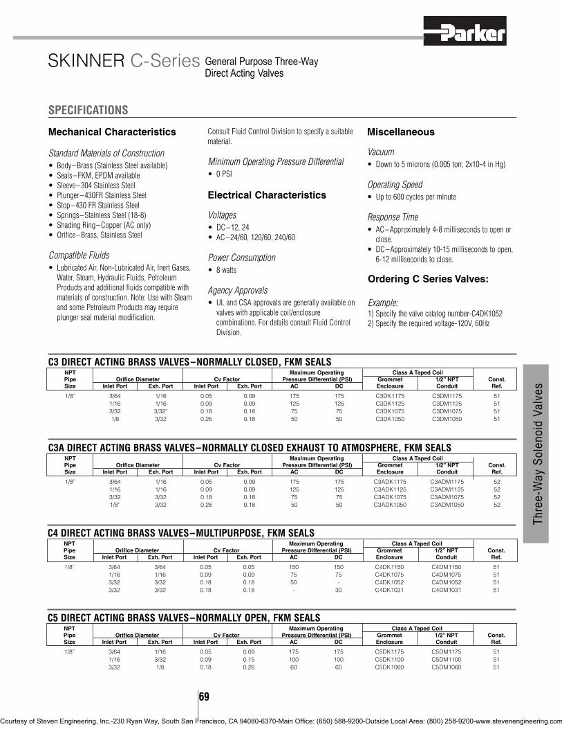
69
Thre
e-W
ay S
olen
oid
Valve
s
Mechanical Characteristics
Standard Materials of Construction• Body–Brass (Stainless Steel available)• Seals–FKM, EPDM available• Sleeve–304 Stainless Steel• Plunger–430FR Stainless Steel• Stop–430 FR Stainless Steel• Springs–Stainless Steel (18-8)• Shading Ring–Copper (AC only)• Orifice–Brass, Stainless Steel
Compatible Fluids• Lubricated Air, Non-Lubricated Air, Inert Gases,
Water, Steam, Hydraulic Fluids, PetroleumProducts and additional fluids compatible withmaterials of construction. Note: Use with Steamand some Petroleum Products may requireplunger seal material modification.
Consult Fluid Control Division to specify a suitablematerial.
Minimum Operating Pressure Differential• 0 PSI
Electrical Characteristics
Voltages• DC–12, 24• AC–24/60, 120/60, 240/60
Power Consumption• 8 watts
Agency Approvals• UL and CSA approvals are generally available on
valves with applicable coil/enclosurecombinations. For details consult Fluid ControlDivision.
Miscellaneous
Vacuum• Down to 5 microns (0.005 torr, 2x10⁻⁴ in Hg)
Operating Speed• Up to 600 cycles per minute
Response Time• AC–Approximately 4-8 milliseconds to open or
close.• DC–Approximately 10-15 milliseconds to open,
6-12 milliseconds to close.
SPECIFICATIONS
SKINNER C-Series General Purpose Three-Way Direct Acting Valves
C3 DIRECT ACTING BRASS VALVES–NORMALLY CLOSED, FKM SEALSNPT Maximum Operating Class A Taped CoilPipe Orifice Diameter Cv Factor Pressure Differential (PSI) Grommet 1/2” NPT Const.Size Inlet Port Exh. Port Inlet Port Exh. Port AC DC Enclosure Conduit Ref.
1/8” 3/64 1/16 0.05 0.09 175 175 C3DK1175 C3DM1175 511/16 1/16 0.09 0.09 125 125 C3DK1125 C3DM1125 513/32 3/32” 0.18 0.18 75 75 C3DK1075 C3DM1075 511/8 3/32 0.26 0.18 50 50 C3DK1050 C3DM1050 51
C3A DIRECT ACTING BRASS VALVES–NORMALLY CLOSED EXHAUST TO ATMOSPHERE, FKM SEALSNPT Maximum Operating Class A Taped CoilPipe Orifice Diameter Cv Factor Pressure Differential (PSI) Grommet 1/2” NPT Const.Size Inlet Port Exh. Port Inlet Port Exh. Port AC DC Enclosure Conduit Ref.
1/8” 3/64 1/16 0.05 0.09 175 175 C3ADK1175 C3ADM1175 521/16 1/16 0.09 0.09 125 125 C3ADK1125 C3ADM1125 523/32 3/32 0.18 0.18 75 75 C3ADK1075 C3ADM1075 521/8” 3/32 0.26 0.18 50 50 C3ADK1050 C3ADM1050 52
C4 DIRECT ACTING BRASS VALVES–MULTIPURPOSE, FKM SEALSNPT Maximum Operating Class A Taped CoilPipe Orifice Diameter Cv Factor Pressure Differential (PSI) Grommet 1/2” NPT Const.Size Inlet Port Exh. Port Inlet Port Exh. Port AC DC Enclosure Conduit Ref.
1/8” 3/64 3/64 0.05 0.05 150 150 C4DK1150 C4DM1150 511/16 1/16 0.09 0.09 75 75 C4DK1075 C4DM1075 513/32 3/32 0.18 0.18 50 - C4DK1052 C4DM1052 513/32 3/32 0.18 0.18 - 30 C4DK1031 C4DM1031 51
C5 DIRECT ACTING BRASS VALVES–NORMALLY OPEN, FKM SEALSNPT Maximum Operating Class A Taped CoilPipe Orifice Diameter Cv Factor Pressure Differential (PSI) Grommet 1/2” NPT Const.Size Inlet Port Exh. Port Inlet Port Exh. Port AC DC Enclosure Conduit Ref.
1/8” 3/64 1/16 0.05 0.09 175 175 C5DK1175 C5DM1175 511/16 3/32 0.09 0.15 100 100 C5DK1100 C5DM1100 513/32 1/8 0.18 0.26 60 60 C5DK1060 C5DM1060 51
Ordering C Series Valves:
Example:1) Specify the valve catalog number-C4DK10522) Specify the required voltage-120V, 60Hz
Courtesy of Steven Engineering, Inc.-230 Ryan Way, South San Francisco, CA 94080-6370-Main Office: (650) 588-9200-Outside Local Area: (800) 258-9200-www.stevenengineering.com

Accessories Part No.
Universal mounting bracket MECHB5Wrench nut V0-233
Metered exhaust adapter V5-1024(air only-type C3 valves)
70
#51
DRAW
INGS
#52
General Purpose Three-Way Direct Acting Valves
C-SeriesVa
lve A
cces
sorie
s
Port Identification:C3 C4 C5
1-IN NC Exhaust2-Cylinder Common Cylinder3-Exhaust NO IN
Port Identification:1-IN/ 2-Cylinder/ 3*-Exhaust
(* not marked)
Universal Mounting bracket MECHB5
C5
C3
C4
Thre
e-W
ay S
olen
oid
Valve
s
Courtesy of Steven Engineering, Inc.-230 Ryan Way, South San Francisco, CA 94080-6370-Main Office: (650) 588-9200-Outside Local Area: (800) 258-9200-www.stevenengineering.com

71
Thre
e-W
ay S
olen
oid
Valve
s
A5 DIRECT ACTING VALVES–NORMALLY OPEN, NBR SEALSPipe Size Orifice Diameter Maximum Operating
Body Sleeve Inlet Outlet Cv Pressure Differential (PSI) Class B Molded Const.NPT NPT Port Port Factor AC DC 1/2” NPT Conduit Ref
1/4” 1/8 3/32 3/32 0.21 250 - A5LB2252 53
3/32 3/32 0.21 - 250 A56LB2251 53
1/8 1/8 0.35 175 - A5LB2177 53
1/8 1/8 0.35 - 175 A56LB2176 53
5/32 5/32 0.45 125 - A5LB2127 53
5/32 5/32 0.45 - 125 A56LB2126 53
Mechanical Characteristics
Standard Materials of Construction• Body–Brass• Seals–NBR• Sleeve–304 Stainless Steel• Plunger–430FR Stainless Steel• Stop–430 FR Stainless Steel• Springs–Stainless Steel (18-8)• Shading Ring–Copper (AC only)• Orifice–Stainless Steel (303)
Compatible Fluids• Lubricated Air, Non-Lubricated Air, Oils, Inert
Gases, and additional fluids compatible withmaterials of construction.
Minimum Operating Pressure Differential• 0 PSI
Pipe Sizes• 1/8” NPT dry seal.
Electrical Characteristics
Voltages• DC–12, 24, 120• AC–24/60, 120/60, 240/60 (other voltages
available upon request)
Power Consumption•16 watts AC, 14 watts DC
Miscellaneous
Vacuum• Down to 5 microns (0.005 torr, 2x10⁻⁴ in Hg)
Operating Speed• Up to 300 cycles per minute
Response Time• AC–Approximately 4-8 milliseconds to open or
close.• DC–Approximately 10-15 milliseconds to open,
6-12 milliseconds to close.
SPECIFICATIONS
SKINNER A-Series General Purpose Three-Way Direct Acting Valves
A3 DIRECT ACTING VALVES–NORMALLY CLOSED, NBR SEALSPipe Size Orifice Diameter Maximum Operating
Body Sleeve Inlet Outlet Cv Pressure Differential (PSI) Class B Molded Const.NPT NPT Port Port Factor AC DC 1/2” NPT Conduit Ref.
1/4” 1/8 3/32 3/32 0.21 250 A3LB2252 533/32 3/32 0.21 - 250 A36LB2251 531/8 1/8 0.35 175 - A3LB2177 531/8 1/8 0.35 - 175 A36LB2176 535/32 5/32 0.45 125 - A3LB2127 535/32 5/32 0.45 - 125 A36LB2126 53
A4 DIRECT ACTING VALVES–MULTIPURPOSE, NBR SEALSPipe Size Orifice Diameter Maximum Operating
Body Sleeve Inlet Outlet Cv Pressure Differential (PSI) Class B Molded Const.NPT NPT Port Port Factor AC DC 1/2” NPT Conduit Ref.
1/4” 1/8 3/32 3/32 0.21 150 - A4LB2152 53
3/32 3/32 0.21 - 150 A46LB2151 53
1/8 1/8 0.35 100 - A4LB2102 53
1/8 1/8 0.35 - 100 A46LB2101 53
5/32” 5/32 0.45 75 - A4LB2077 53
5/32 5/32 0.45 - 75 A46LB2076 53
Ordering A Series Valves:
Example:1) Specify the valve catalog number-A36LB22512) Specify the required voltage-12 VDC
Courtesy of Steven Engineering, Inc.-230 Ryan Way, South San Francisco, CA 94080-6370-Main Office: (650) 588-9200-Outside Local Area: (800) 258-9200-www.stevenengineering.com

72
#53
DRAW
INGS
General Purpose Three-Way Direct Acting Valves
A-Series
A6 DIRECT ACTING VALVES–DIRECTIONAL CONTROL, NBR SEALSPipe Size Orifice Diameter Maximum Operating
Body Sleeve Inlet Outlet Cv Pressure Differential (PSI) Class B Molded Const.NPT NPT Port Port Factor AC DC 1/2” NPT Conduit Ref
1/4” 1/8 3/32 3/32 0.21 250 - A6LB2252 533/32 3/32 0.21 - 250 A66LB2251 531/8 1/8 0.35 175 - A6LB2177 531/8 1/8 0.35 - 175 A66LB2176 535/32 5/32 0.45 125 - A6LB2127 535/32 5/32 0.45 - 125 A66LB2126 53
Port Identification:A3 A4 A5 A6
IN NC Exhaust NCCylinder Common Cylinder INExhaust NO IN NO
A3 A4
A5 A6
Thre
e-W
ay S
olen
oid
Valve
s
PAE
Courtesy of Steven Engineering, Inc.-230 Ryan Way, South San Francisco, CA 94080-6370-Main Office: (650) 588-9200-Outside Local Area: (800) 258-9200-www.stevenengineering.com

73
Four-Way Valve
Skinner Four-Way Valve Specifications.............. 74-84
Skinner 7000 Series Valves ............................ 74-80Direct Acting Valves ................................ 74-75Pilot Operated Valves .............................. 76-80
Skinner V-9 Series Valves .............................. 81-84
Courtesy of Steven Engineering, Inc.-230 Ryan Way, South San Francisco, CA 94080-6370-Main Office: (650) 588-9200-Outside Local Area: (800) 258-9200-www.stevenengineering.com

74
Courtesy of Steven Engineering, Inc.-230 Ryan Way, South San Francisco, CA 94080-6370-Main Office: (650) 588-9200-Outside Local Area: (800) 258-9200-www.stevenengineering.com
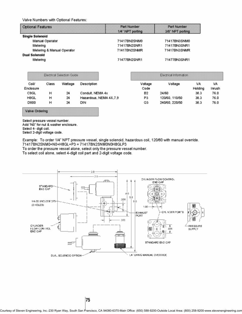
75
Courtesy of Steven Engineering, Inc.-230 Ryan Way, South San Francisco, CA 94080-6370-Main Office: (650) 588-9200-Outside Local Area: (800) 258-9200-www.stevenengineering.com

Mechanical Characteristics
Standard Materials of Construction• Body–Aluminum Alloy, Zinc Alloy (epoxy
coated)• Seals–NBR• Sleeve Tube–Stainless Steel (303)• Plunger–Stainless Steel (430FR)• Stop–Stainless Steel (430FR)• Springs–Stainless Steel (18-8)• Shading Rings–Copper• Pilot Orifice–Stainless Steel (303)
Compatible Fluids• Lubricated Air, Non-Lubricated Air, Inert Gases.
Use of non-lubricated gaseous media willsubstantially limit valve life.
Electrical Characteristics
Voltages• DC–12, 24• AC–24/60, 110/50-120/60, 220/50-240/60,
(other AC/DC voltages available upon request)
Agency Approval• UL and CSA approvals are available on valves
with applicable coil/enclosure combinations. Foradditional information see page 122.
Miscellaneous
Maximum Ambient Temperature• 10 watt AC/DC–150°F• 22 watt AC/DC–77°F• Fluxtron/Magnelatch–122°F
SPECIFICATIONS
SKINNER 7000 Series General Purpose Four-Way Pilot Operated Valves
* GP=General Purpose Valves. See page 122 for additional agency approval information.
#54
DRAW
INGS
#55
7341 PILOT OPERATED VALVES–NBR SEALSOperating Pressure Differential (PSI) MAX.
Pipe Orifice Maximum Fluid Pressure Size Size Cv AC Ratings DC Ratings Temp. Vessel UL/CSA* Const.NPT (inch) Factor Min. 10 watt 22 watt 10 watt 22 watt (F) Number Approval Ref.
1/8” 5/32 0.35 15 150 150 165 7341LAN1HNM0 GP 54
1/4” 5/16 1.4 15 150 150 165 7341LMN2NNM0 GP 55
Port Identification:Pressure Cyl. A Exh. A Cyl. B Exh. B
1 2 3 4 5
Port Identification:Pressure Cyl. A Exh. A Cyl. B Exh. B
1 2 3 4 5
76
Four
-Way
Sol
enoi
d Va
lves
Courtesy of Steven Engineering, Inc.-230 Ryan Way, South San Francisco, CA 94080-6370-Main Office: (650) 588-9200-Outside Local Area: (800) 258-9200-www.stevenengineering.com

77
Mechanical Characteristics
Standard Materials of Construction• Body–Aluminum• Seals–NBR• Spool–Aluminum• Sleeve Tube–Stainless Steel (304)• Plunger–Stainless Steel (430FR)• Stop–Stainless Steel (430FR)• Springs–Stainless Steel (18-8)• Shading Rings–Copper
Compatible Fluids• Lubricated Air, Non-Lubricated Air, Inert Gases.
Use of non-lubricated gaseous media willsubstantially limit valve life.
Electrical Characteristics
Voltages• DC–12, 24• AC–24/60, 110/50-120/60, 220/50-240/60,
(other AC/DC voltages available upon request)
Agency Approval• UL and CSA approvals are available on valves
with applicable coil/enclosure combinations. Foradditional information see page 122.
Miscellaneous
Maximum Ambient Temperature• 10 watt AC/DC–150°F• 22 watt AC/DC–77°F• Fluxtron/Magnelatch–122°F• Internal Leakage - 8cc/min max
SPECIFICATIONS
SKINNER 7000 Series General Purpose Four-Way Pilot and Manually Operated Valves
** GP=General Purpose Valves. See page 122 for additional agency approval information.
#56
DRAW
INGS
#57
7341 PILOT OPERATED ALUMINUM SOLENOID OPERATED VALVES–NBR SEALSOperating Pressure Differential (PSI) MAX.
Pipe Orifice Maximum Fluid Pressure Size Size Cv AC Ratings DC Ratings Temp. Vessel UL/CSA** Const.NPT (inch) Factor Min.* 10 watt 22 watt 10 watt 22 watt (F) Number Approval Ref.
1/4” 1/4 1 30 150 150 165 73419AN2NN00 GP 561/4 1 30 150 150 165 73419AN2NNM0 GP 56
7541 REMOTE AIR PILOT OPERATED ALUMINUM VALVE–NBR SEALSPipe Orifice Operating Pressure Pressure Size Size Cv Differential (PSI) Vessel Const.NPT (inch) Factor Min. Max. Number Ref.
1/4" 1/4 1 * 150 75419AN2NN00 57
* Remote pilot pressure to operate the valve = 20 PSI + 1/3 (main line pressure)
Port Identification:Pressure Cyl. A Exh. A Cyl. B Exh. B
P A EA B EB
Port Identification:Pressure Cyl. A Exh. A Cyl. B Exh. B
P A EA B EB
Courtesy of Steven Engineering, Inc.-230 Ryan Way, South San Francisco, CA 94080-6370-Main Office: (650) 588-9200-Outside Local Area: (800) 258-9200-www.stevenengineering.com

78
Four
-Way
Sol
enoi
d Va
lves
General Purpose Sealed Four-Way Pilot and Manually Operated Valves
7000 Series
Two-position spool valves are available withno spring return, spring return with cylinderA port open, or spring return with cylinder Bport open. Spring return models require theoperator to move the handle in one directionand hold it to provide the function. The no-
spring model will remain in either positionwithout holding.
A three-position spool valve is availablewith all ports closed in its normal position.The handle is moved and held in one
direction to open one cylinder port and tothe opposite direction to open the othercylinder port. The spool is spring centeredand the handle is normally in the center orupright position.
Valve 76419AN2NNCB: Two-position,Spring Return, cylinder “B” Open. On thisvalve, cylinder “B” is open to the pressureinlet. To open cylinder “A” to pressure, thelever must be moved away from the valveand held in this position. Once released, thespring will return the spool to open cylinder “B”.
Valve 76429AN2NN00: Three-Position,Spring Centered, All Ports Closed. On thismodel the spring and retainers are designedso that the spool is centered, all ports areclosed, and the hand lever is in the centerposition. When the lever is moved towardthe valve and held, cylinder “B” is open topressure and cylinder “A” is open to exhaust.When the lever is moved away from thevalve and held, cylinder “A” is open topressure and cylinder “B” is open to exhaust.
Valve 76469AN2NN00: Two-position No Spring Return. Permits the operator toopen cylinder “B” to pressure and cylinder“A” to exhaust when the lever is movedforward, and to reverse the process when thelever is moved in the opposite direction.Since there is no spring, the spool can beleft in either position.
#58
DRAW
INGS
Hand Lever Operated Valves
Types of Operation
Pipe Orifice Operating PressureSize Size Cv Differential (PSI) Catalog Const.NPT (inch) Factor Minimum Maximum Number Ref.
1/4” 1/4 1 0 150 76419AN2NNCB 581/4 1 0 150 76429AN2NN00 581/4 1 0 150 76469AN2NN00 58
Hand Lever Operated Valves
Courtesy of Steven Engineering, Inc.-230 Ryan Way, South San Francisco, CA 94080-6370-Main Office: (650) 588-9200-Outside Local Area: (800) 258-9200-www.stevenengineering.com

79
Four
-Way
Sol
enoi
d Va
lves
Mechanical Characteristics
Standard Materials of Construction• Body– Brass or 303 Stainless Steel• Seals–NBR• Spool–Thermoplastic• Cages–Thermoplastic• Sleeve Tube–Stainless Steel (304)• Plunger–Stainless Steel (430FR)• Stop–Stainless Steel (430FR)• Springs–Stainless Steel (18-8 or 17-4)• Filter–Polyethylene
Compatible Fluids• Lubricated Air, Non-Lubricated Air, Inert Gases
and other gases compatible with materials ofconstruction.
Electrical Characteristics
Voltages• DC–12, 24• AC–24/60, 110/50-120/60, 220/50-240/60
(other voltages available upon request)
Agency Approval• UL approvals are available on valves with
applicable coil/enclosure combinations. Foradditional information see page 122.
Miscellaneous
Minimum Ambient Temperature• -40°F(-40°C)
Dew point must be more than 7°F belowambient.
Maximum Ambient Temperature• 10 watt AC/DC–150°F• 22 watt AC/DC–77°F• Fluxtron/Magnelatch–122°F
SPECIFICATIONS
SKINNER 7000 Series General Purpose Four-Way Pilot Operated Valves
* Pilot operated valves require the minimum pressure differential specified for proper valve operation. ** GP=General Purpose Valves. See page 122 for additional agency approval information.
7341, 7347 PILOT OPERATED BRASS OR STAINLESS STEEL VALVES NBR SEALSOperating Pressure Differential (PSI) MAX.
Pipe Orifice Maximum Fluid Brass StainlessSize Size Cv Flow AC Ratings DC Ratings Temp. Pressure Vessel Pressure Vessel UL/CSA** Const.NPT (inch) Factor Min.* 10 watt 22 watt 10 watt 22 watt (F) Catalog Number Catalog Number Approval Ref.
Single Solenoid1/4” 11/64 0.55 30 150 150 167 73417BN2KN00 73417VN2KN00 GP 135
1/4 1.2 30 150 150 167 73417BN2PN00 73417VN2PN00 GP 135
1/2” 5/8 4.0 30 150 150 167 73417BN4UN00 - GP 137Double Solenoid
1/4” 11/64 0.55 30 150 150 167 73477BN2KN00 73477VN2KN00 GP 1361/4 1.2 30 150 150 167 73477BN2PN00 73477VN2PN00 GP 136
1/2” 5/8 4.0 30 150 150 167 73477BN4UN00 - GP 137
Courtesy of Steven Engineering, Inc.-230 Ryan Way, South San Francisco, CA 94080-6370-Main Office: (650) 588-9200-Outside Local Area: (800) 258-9200-www.stevenengineering.com

80
#135
DRAW
INGS
#136
General Purpose Four-Way Pilot Operated Valves
7000 Series
#137
Four
-Way
Sol
enoi
d Va
lves
Courtesy of Steven Engineering, Inc.-230 Ryan Way, South San Francisco, CA 94080-6370-Main Office: (650) 588-9200-Outside Local Area: (800) 258-9200-www.stevenengineering.com

81
Four
-Way
Sol
enoi
d Va
lves
Mechanical Characteristics
Standard Materials of Construction• Body–Zinc• Seals–NBR• Sleeve–Stainless Steel (304)• Plunger–Stainless Steel (430FR)• Shading Ring–Copper (AC & DC only)• Stop–Stainless Steel (430FR)• Springs–Stainless Steel (18-8)• Orifice–Stainless Steel (303)
Compatible Fluids• Lubricated Air, Non-Lubricated Air, Inert Gases,
Hydraulic Fluids, and additional fluidscompatible with materials of construction.
Electrical Characteristics
Voltages• DC–12, 24, 120• AC–24/60, 120/60, 240/60
Power Consumption• 10 watts per coil (2 coils)
Agency Approvals• UL and CSA approvals are generally available
on valves with applicable coil/enclosurecombinations. For details, please consultSkinner Valve.
Miscellaneous
Operating Speed• Up to 600 cycles per minute.
Response Time• AC–Approximately 4-8 milliseconds to open or
close.• DC–Approximately 10-15 milliseconds to open,
6-12 milliseconds to close.
SPECIFICATIONS
SKINNER V-9 SeriesFour-Way Direct Acting Valves
When de-energized, both inlet ports areclosed by the two plungers preventing flowfrom the common inlet through both of thevalves. The cylinder port in each valve is
open to the common exhaust, permittingflow from the cylinders to the exhaust. Whenthe coils are energized, both valve plungersrise, opening the inlet orifices, and at the
same time closing the orifices in the sleeves.This stops flow from the cylinder ports to theexhaust, and permits flow from the inlet tothe cylinder ports.
Typical Cylinder Operation with V933 Valves.Both coils de-energized–The inlet pressure is closed to both sides of a double-actingcylinder. Side #1 and side #2 of the cylinder are open to exhaust through cylinder ports #C1 and #C2. The piston can be shifted manually.
Coil of valve #1 energized; coil of valve #2 de-energized–The inlet pressure is open to side#1 of the double-acting cylinder through cylinder port #C1, the exhaust is closed off by theplunger insert. Side #2 of the cylinder is open to exhaust through cylinder port #C2, the inletis closed off by the plunger insert. The piston moves to the right.
Coil of valve #1 de-energized; coil of valve #2 energized–The inlet pressure is closed off toside #1 of the double-acting cylinder; the exhaust is open through cylinder port #C1. Side #2of the cylinder is closed to the exhaust and open to inlet pressure through cylinder port #C2.The piston moves to the left.
V933 Four-Way Normally Closed–Normally Closed Valves
Ordering V9 Valves:
Example:1) Specify the valve catalog number-V935LB21502) Specify the required voltage-120V, 60Hz
Coil Class• Class B, Class H coils available upon request.
Courtesy of Steven Engineering, Inc.-230 Ryan Way, South San Francisco, CA 94080-6370-Main Office: (650) 588-9200-Outside Local Area: (800) 258-9200-www.stevenengineering.com
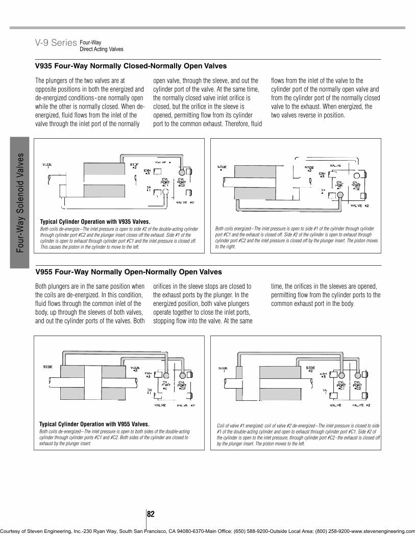
82
The plungers of the two valves are atopposite positions in both the energized andde-energized conditions-one normally openwhile the other is normally closed. When de-energized, fluid flows from the inlet of thevalve through the inlet port of the normally
open valve, through the sleeve, and out thecylinder port of the valve. At the same time,the normally closed valve inlet orifice isclosed, but the orifice in the sleeve isopened, permitting flow from its cylinderport to the common exhaust. Therefore, fluid
flows from the inlet of the valve to thecylinder port of the normally open valve andfrom the cylinder port of the normally closedvalve to the exhaust. When energized, thetwo valves reverse in position.
Both plungers are in the same position whenthe coils are de-energized. In this condition,fluid flows through the common inlet of thebody, up through the sleeves of both valves,and out the cylinder ports of the valves. Both
orifices in the sleeve stops are closed to the exhaust ports by the plunger. In theenergized position, both valve plungersoperate together to close the inlet ports,stopping flow into the valve. At the same
time, the orifices in the sleeves are opened,permitting flow from the cylinder ports to thecommon exhaust port in the body.
Typical Cylinder Operation with V935 Valves.Both coils de-energize–The inlet pressure is open to side #2 of the double-acting cylinderthrough cylinder port #C2 and the plunger insert closes off the exhaust. Side #1 of thecylinder is open to exhaust through cylinder port #C1 and the inlet pressure is closed off.This causes the piston in the cylinder to move to the left.
Typical Cylinder Operation with V955 Valves.Both coils de-energized–The inlet pressure is open to both sides of the double-actingcylinder through cylinder ports #C1 and #C2. Both sides of the cylinder are closed toexhaust by the plunger insert.
Coil of valve #1 energized; coil of valve #2 de-energized–The inlet pressure is closed to side#1 of the double-acting cylinder and open to exhaust through cylinder port #C1. Side #2 ofthe cylinder is open to the inlet pressure, through cylinder port #C2- the exhaust is closed offby the plunger insert. The piston moves to the left.
Both coils energized–The inlet pressure is open to side #1 of the cylinder through cylinderport #C1 and the exhaust is closed off. Side #2 of the cylinder is open to exhaust throughcylinder port #C2 and the inlet pressure is closed off by the plunger insert. The piston movesto the right.
Four-Way Direct Acting Valves
V-9 Series
V935 Four-Way Normally Closed-Normally Open Valves
V955 Four-Way Normally Open-Normally Open Valves
Four
-Way
Sol
enoi
d Va
lves
Courtesy of Steven Engineering, Inc.-230 Ryan Way, South San Francisco, CA 94080-6370-Main Office: (650) 588-9200-Outside Local Area: (800) 258-9200-www.stevenengineering.com

V935 ZINC VALVES–NORMALLY CLOSED-NORMALLY OPEN NON-NEUTRAL POSITION, NBR SEALS
Orifice Diameters *MaximumNPT Valve #1 (NC) Valve #2 (NO) Operating Class BPipe Inlet Cv Exhaust Cv Inlet Cv Exhaust Cv Pressure Molded Const.Size Port Factor Port Factor Port Factor Port Factor Diff. (PSI) Leaded Coil Ref.
1/4” 3/64 0.052 1/16 0.095 3/64 0.052 1/16 0.095 150 (200) V935LB2150 591/16 0.095 3/32 0.14 1/16 0.08 1/8 0.18 100 (125) V935LB2100 593/32 0.16 3/32 0.14 3/32 0.14 1/8 0.21 75 (90) V935LB2075 591/8 0.21 3/32 0.14 3/32 0.14 1/8 0.21 50 (65) V935LB2050 59
83
V933 ZINC VALVES–NORMALLY CLOSED-NORMALLY CLOSED NEUTRAL POSITION–WITH ADJUSTABLE FLOW OPTION, NBR SEALS
Orifice Diameters *Maximum Class B Molded Leaded CoilNPT Valve #1 (NC) Valve #2 (NC) Operating Adjustable Flow Adjustable Flow Full AdjustablePipe Inlet Cv Exhaust Cv Inlet Cv Exhaust Cv Pressure At Both At Both Flow At Both Const.Size Port Factor Port Factor Port Factor Port Factor Diff. (PSI) Exhausts Inlets Exhausts & Inlets Ref.
1/4” 3/64 0.052 1/16 0.095 3/64 0.052 1/16 0.095 150 (200) V933LEH2150 V933LEP2150 V933LEF2150 591/16 0.105 3/32 0.13 1/16 0.105 3/32 0.13 100 (125) V933LEH2100 V933LEP2100 V933LEF2100 593/32 0.13 3/32 0.13 3/32 0.13 3/32 0.13 75 (90) V933LEH2075 V933LEP2075 V933LEF2075 591/8 0.16 3/32 0.13 1/8 0.16 3/32 0.13 50 (65) V933LEH2050 V933LEP2050 V933LEF2050 59
Coil of valve #1 de-energized; coil of valve #2 energized–The inlet pressure is open to side#1 of the cylinder through cylinder port #C1 and the exhaust is closed off by the plungerinsert. Side #2 of the cylinder is open to exhaust through the cylinder port #C2 and theplunger insert closes off the inlet pressure. The piston moves to the right.
Four-Way Direct Acting Valves
V-9 Series
* Figures in parentheses indicate higher than standard pressure ratings available with slightmodifications.
V933 ZINC VALVES–NORMALLY CLOSED-NORMALLY CLOSED NEUTRAL POSITION, NBR SEALS
Orifice Diameters *MaximumNPT Valve #1 (NC) Valve #2 (NC) Operating Class BPipe Inlet Cv Exhaust Cv Inlet Cv Exhaust Cv Pressure Molded Const.Size Port Factor Port Factor Port Factor Port Factor Diff. (PSI) Leaded Coil Ref.
1/4” 3/64 0.052 1/16 0.095 3/64 0.052 1/16 0.095 150 (200) V933LB2150 591/16 0.095 3/32 0.14 1/16 0.095 3/32 0.14 100 (125) V933LB2100 593/32 0.16 3/32 0.14 3/32 0.16 3/32 0.14 75 (90) V933LB2075 591/8 0.21 3/32 0.14 1/8 0.21 3/32 0.14 50 (65) V933LB2050 59
V955 ZINC VALVES–NORMALLY OPEN-NORMALLY OPEN NEUTRAL POSITION, NBR SEALSOrifice Diameters *Maximum
NPT Valve #1 (NO) Valve #2 (NO) Operating Class BPipe Inlet Cv Exhaust Cv Inlet Cv Exhaust Cv Pressure Molded Const.Size Port Factor Port Factor Port Factor Port Factor Diff. (PSI) Leaded Coil Ref.
1/4” 3/64 0.052 1/16 0.095 3/64 0.052 1/16 0.095 150 (225) V955LB2150 591/16 0.08 1/8 0.18 1/16 0.08 1/8 0.18 100 (150) V955LB2100 593/32 0.14 1/8 0.18 3/32 0.14 1/8 0.21 75 (100) V955LB2075 59
Four
-Way
Sol
enoi
d Va
lves
Courtesy of Steven Engineering, Inc.-230 Ryan Way, South San Francisco, CA 94080-6370-Main Office: (650) 588-9200-Outside Local Area: (800) 258-9200-www.stevenengineering.com

84
V955 ZINC VALVES–NORMALLY OPEN-NORMALLY OPEN NEUTRAL POSITION–WITH ADJUSTABLE FLOW OPTION, NBR SEALS
Orifice Diameters *Maximum Class B Molded Leaded CoilNPT Valve #1 (NO) Valve #2 (NO) Operating Adjustable Flow Adjustable Flow Full AdjustablePipe Inlet Cv Exhaust Cv Inlet Cv Exhaust Cv Pressure At Both At Both Flow At Both Const.Size Port Factor Port Factor Port Factor Port Factor Diff. (PSI) Exhausts Inlets Exhausts & Inlets Ref.
1/4” 3/64 0.052 1/16 0.095 3/64 0.052 1/16 0.095 150 (225) V955LEH2150 V955LEP2150 V955LEF2150 591/16 0.08 1/8 0.16 1/16 0.08 1/8 0.16 100 (150) V955LEH2100 V955LEP2100 V955LEF2100 593/32 0.13 1/8 0.16 3/32 0.13 1/8 0.16 75 (100) V955LEH2075 V955LEP2075 V955LEF2075 59
Four-Way Direct Acting Valves
V-9 Series
* Figures in parentheses indicate higher than standard pressure ratings available with slightmodifications.
#59
Four-Way Normally Closed-Normally Closed
Four-Way Normally Closed-Normally Open
Four-Way Normally Open-Normally Open
DRAW
INGS
V935 ZINC VALVES–NORMALLY CLOSED–NORMALLY OPEN NON-NEUTRAL POSITION–WITH ADJUSTABLE FLOW OPTION, NBR SEALS
Orifice Diameters *Maximum Class B Molded Leaded CoilNPT Valve #1 (NC) Valve #2 (NO) Operating Adjustable Flow Adjustable Flow Full AdjustablePipe Inlet Cv Exhaust Cv Inlet Cv Exhaust Cv Pressure At Both At Both Flow At Both Const.Size Port Factor Port Factor Port Factor Port Factor Diff. (PSI) Exhausts Inlets Exhausts & Inlets Ref.
1/4” 3/64 0.052 1/16 0.095 3/64 0.052 1/16 0.095 150 (200) V935LEH2150 V935LEP2150 V935LEF2150 59
1/16 0.105 3/32 0.13 1/16 0.08 1/8 0.16 100 (125) V935LEH2100 V935LEP2100 V935LEF2100 59
3/32 0.13 3/32 0.13 3/32 0.13 1/8 0.16 75 (90) V935LEH2075 V935LEP2075 V935LEP2075 59
1/8 0.16 3/32 0.13 3/32 0.13 1/8 0.16 50 (65) V935LEH2050 V935LEP2050 V935LEF2050 59
For ordering instructions see Ordering Information section on page 10.
Note: Enclosure and adjustable flowdesignators (B, EH, EP OR EF) have been omitted for brevity.
Four
-Way
Sol
enoi
d Va
lves
Courtesy of Steven Engineering, Inc.-230 Ryan Way, South San Francisco, CA 94080-6370-Main Office: (650) 588-9200-Outside Local Area: (800) 258-9200-www.stevenengineering.com

Skinner Specialty Valve Specifications .............. 86-90
Skinner 7000 Series Valves .................................. 86Hydraulic Two-Way Valves ............................ 86Dry Operator Valves ................................ 87-89Hydraulic Three-Way Valves .......................... 90
Skinner Dual-Flow Valves .................................... 91Skinner BP Proportional Valves ...................... 92-93Skinner Intrinsically Safe Valves .................. 94-107
Intrinsically Safe Two-Way Valves............ 95-96Intrinsically Safe Tree-Way Valves............ 97-98Intrinsically Safe Special Purpose Valves ...... 99Intrinsically Safe Four-Way Valves ...... 100-101Coil and Enclosure Information............ 102-107
Skinner A-10 Series Valves ........................ 108-109Skinner MB Series Valves .......................... 110-111
Electropneumatic Pressure Regulator (EPP3) ..................................112-113
Specialty Valve Contents
Courtesy of Steven Engineering, Inc.-230 Ryan Way, South San Francisco, CA 94080-6370-Main Office: (650) 588-9200-Outside Local Area: (800) 258-9200-www.stevenengineering.com

Spec
ialty
Val
ves
86
Product Description
Skinner Hydraulic valves are specifically designedfor use in hydraulic systems. The valves are spooltype valves that can withstand a static pressure upto 1000 PSI. All internal parts are compatible withmost hydraulic fluids.
Mechanical Characteristics
Standard Materials of Construction• Body–Stainless Steel (430F)• Seals–Metal (spool type)• Sleeve Tube–Stainless Steel (304)• Armature–Stainless Steel (430FR)• Stop–Stainless Steel (430FR)• Springs–Stainless Steel (18-8)• Shading Rings–Copper• Spool–Stainless Steel (17-4PH)• Flange Seal– NBR
Compatible Fluids• Hydraulic Fluids.
Electrical Characteristics
Voltages• DC–12, 24• AC–24/60, 110/50-120/60, 220/50-240/60,
(other AC/DC voltages available upon request)
Power Consumption• 10 watts
Agency Approvals• UL and CSA approvals are available on valves
with applicable coil/enclosure combinations. Foradditional information see page 122.
Valve Construction Alternatives
Mounting• Manifold, flange and cage types available.
Consult factory for details.
Miscellaneous
Maximum Ambient Temperature• 10 watt AC/DC–150°F• Fluxtron/Magnelatch–122°F
Leakage• Internal–At 70°F with MIL-H-5606 oil,
maximum allowable leakage is 80cc/min. at 1000PSI.
• External–None
SPECIFICATIONS
SKINNER 7000 Series Hydraulic Two-Way Direct Acting Valves
* UL/CSA Approval Information: SS=safety Shutoff GP=General Purpose Blank=Not ApprovedSee page 136 for additional agency approval information.
#60
DRAW
INGS
DIRECT ACTING STAINLESS STEEL VALVES–NORMALLY CLOSEDStatic Pressure (PSI) MAX.
Pipe Orifice Maximum Fluid Pressure Size Size Cv AC Rating DC Rating Temp. Vessel UL/CSA* Const.NPT (inch) Factor Min. 10 watt 10 watt (F) Number Approval Ref.
1/8” 7/64 0.21 0 1000 1000 185 71211SN1MM00 GP 60
DIRECT ACTING STAINLESS STEEL VALVES–NORMALLY OPENStatic Pressure (PSI) MAX.
Pipe Orifice Maximum Fluid Pressure Size Size Cv AC Rating DC Rating Temp. Vessel UL/CSA* Const.NPT (inch) Factor Min. 10 watt 10 watt (F) Number Approval Ref.
1/8” 7/64 0.21 0 1000 1000 185 71221SN1MM00 GP 60
Port Identification:71211 712211-IN 1-Plug
2-OUT 2-OUT3-Plug 3-IN
NORMALLY CLOSED NORMALLY OPEN
For mechanical option S2, silver shading ring and Teflon flangeseal, substitute S2 for 00 in the part number.
Courtesy of Steven Engineering, Inc.-230 Ryan Way, South San Francisco, CA 94080-6370-Main Office: (650) 588-9200-Outside Local Area: (800) 258-9200-www.stevenengineering.com

Spec
ialty
Val
ves
87
Important ApplicationInformation On Back Pressure Data
Dry operator valves require consideration ofback pressure since the back pressure actson a large area of the diaphragm. Excessiveback pressure can keep the valves open onde-energization. The back pressure astandard valve can operate against dependson the orifice size, pressure differential andwhether the media is a gas or liquid.
The following two charts provide a methodto verify that the valve selected can meet theapplication back pressure requirements.
For applications involving back pressurethat cannot be handled by catalog valves,please consult Skinner Valve.
Helpful ApplicationSuggestions:
To keep the back pressure to a minimum, thedownstream line should be as short aspossible and be of the largest practical size.All restricting or flow controlling elementsshould be installed upstream.
Use of Back Pressure Charts:
To use the charts, it is necessary to know theflow and back pressure.
1) First calculate the flow in GPM forliquids or SCFM for gases from the flowcharts in the Technical Information Section.
2) The back pressure is the downstreampressure in the system. A catalog valve maybe used if the intersection of flow and backpressure is below the curve for its orifice size.
Product Description
The 7000 Series Dry Operator valve line is speciallydesigned for non-contaminating and corrosiveapplications. The valves assure absolute purity andinertness to corrosion when used with a broadrange of fluids.
Dry Operator valves feature two basic construc-tion innovations. The operator is physically isolatedfrom the fluid by a diaphragm so only the seal andvalve body come in contact with the fluid. And,valve bodies of Noryl and Teflon provide the purityfrom contamination and resistance to corrosionmany industries demand.
Mechanical Characteristics
Standard Materials of Construction• Body–Noryl, Teflon, Stainless Steel (303)• Seals–PTFE and FKM as listed.
• Sleeve Tube–Stainless Steel (304)• Plunger–Stainless Steel (430FR)• Stop–Stainless Steel (430FR)• Springs–Stainless Steel (18-8)• Shading Ring–Copper
Compatible Fluids• Fluids compatible with diaphragm and body
materials. See Fluid Compatibility Chart.
Electrical Characteristics
Voltages• DC–12, 24• AC –24/60, 110/50-120/60, 220/50-240/60,
(consult factory for other voltages)
Power Consumption• 10, 22 watts
Agency Approvals• UL and CSA approvals are available on valves
with applicable coil/enclosure combinations. Foradditional information see page 122.
Miscellaneous
Maximum Ambient Temperature• 10 watt AC/DC–150°F• 22 watt AC/DC–77°F
SPECIFICATIONS
SKINNER 7000 Series Dry Operator Two-Way Direct Acting Valves
Courtesy of Steven Engineering, Inc.-230 Ryan Way, South San Francisco, CA 94080-6370-Main Office: (650) 588-9200-Outside Local Area: (800) 258-9200-www.stevenengineering.com

* UL/CSA Approval Information: SS=Safety Shutoff GP=General Purpose Blank=Not Approved See page 122 for additional agency approval information.
DIRECT ACTING NORYL VALVES–NORMALLY CLOSED, 3/8” BARB, FKM SEALSOperating Pressure Differential (PSI) MAX.
Pipe Orifice Maximum Fluid Pressure Size Size Cv AC Ratings DC Ratings Temp. Vessel UL/CSA* Const.NPT (inch) Factor Min. 10 watt 22 watt 10 watt 22 watt (F) Number Approval Ref.
3/8” BARB 5/32 0.35 0 35 35 140 71214LT3QV00 GP 623/16 0.47 0 20 20 140 71214LT3SV00 GP 62
DIRECT ACTING STAINLESS STEEL VALVES–NORMALLY CLOSED, 1/4” NPT, PTFE SEALSOperating Pressure Differential (PSI) MAX.
Pipe Orifice Maximum Fluid Pressure Size Size Cv AC Ratings DC Ratings Temp. Vessel UL/CSA* Const.NPT (inch) Factor Min. 10 watt 22 watt 10 watt 22 watt (F) Number Approval Ref.
1/4” NPT 3/16 0.47 0 20 20 140 71214VN2ST00 GP 4
88
Dry Operator Two-WayDirect Acting Valves
7000 Series
Spec
ialty
Val
ves
DIRECT ACTING TEFLON VALVES–NORMALLY CLOSED, 1/4” NPT, PTFE SEALSOperating Pressure Differential (PSI) MAX.
Pipe Orifice Maximum Fluid Pressure Size Size Cv AC Ratings DC Ratings Temp. Vessel UL/CSA* Const.NPT (inch) Factor Min. 10 watt 22 watt 10 watt 22 watt (F) Number Approval Ref.
1/4” NPT 5/64 0.16 0 70 70 140 71214TN2KT00 GP 633/16 0.47 0 20 20 140 71214TN2SV00 GP 633/16 0.47 0 20 20 140 71214TN2ST00 GP 63
Courtesy of Steven Engineering, Inc.-230 Ryan Way, South San Francisco, CA 94080-6370-Main Office: (650) 588-9200-Outside Local Area: (800) 258-9200-www.stevenengineering.com

Port Identification:Flow area on body indicates flowdirection–ports are not marked.
89
Dry Operator Two-Way Direct Acting Valves
7000 Series
#62
#63#4
DRAW
INGS
Port Identification: 1-OUT/ 2- INPort Identification:
1-OUT/ 2-IN
Spec
ialty
Val
ves
Courtesy of Steven Engineering, Inc.-230 Ryan Way, South San Francisco, CA 94080-6370-Main Office: (650) 588-9200-Outside Local Area: (800) 258-9200-www.stevenengineering.com

3 WAY MULTIPURPOSE HYDRAULIC VALVESOrifice Orifice Static Pressure (PSI) Max.
Pipe Body Body Cv Cv Maximum FluidSize NC NO Factor Factor AC Ratings DC Ratings Temp. Pressure Vessel UL/CSA* Const.NPT (inch) (inch) NC NO Min. 10 watt 22 watt 10 watt 22 watt (F) Catalog Number Approval Ref.1/8” 7/64 7/64 0.21 0.21 0 1000 1000 185 71331SN1MM00 GP 91
Product Description
Specifically designed for use in hydraulic systems,these valves are spool type valves that can with-stand a static pressure up to 1000 PSI. All internalparts are compatible with most hydraulic fluids. A range of custom mounting types are availableincluding manifold, flange and cage designs.
Mechanical Characteristics
Standard Materials of Construction• Body–Stainless Steel (430F)• Seals–Metal• Flange Seal–NBR• Sleeve Tube–Stainless Steel (304)• Plunger–Stainless Steel (430FR)• Stop–Stainless Steel (430FR)• Springs–Stainless Steel (18-8)• Shading Ring–Copper• Spool–Stainless Steel (17-4PH)
Compatible Fluids• Hydraulic Fluids.
Electrical Characteristics
Voltages• DC–12, 24• AC–24/60, 110/50-120/60, 220/50-240/60,
(other AC/DC voltages available upon request)
Power Consumption• 10
Agency Approvals• Ul and CSA approvals are available on valves
with applicable coil/enclosure combinations. Foradditional information see page 122.
Miscellaneous
Leakage• Internal– At 70°F with MIL-H-5606 oil,
maximum allowable leakage is 80cc/min. at1000PSI.
• External–None.
Maximum Ambient Temperature• 10 watt AC/DC–150°F• 22 watt AC/DC–77°F• Fluxtron/ Magnelatch–122°F
Valve Construction Alternatives
Mounting• Manifold, flange and cage types available.
Consult factory for details.
SPECIFICATIONS
SKINNER Hydraulic 7000 Series Three-Way Direct Acting Valves
* UL/CSA Approval Information: GP=General Purpose Blank=Not Approved See page 122 for additional agency approval information.
#91
DRAW
INGSMAXIMUM PERMISSIBLE FLOW
AND PRESSURE DIFFERENTIALSMaximum
Valve Function Maximum PressureValve Function Flow Path Flow (GPM) Differential (PSI)
71311SN1MM00 1 to 2 5.70 700Normally Closed 2 to 3 5.70 700
71321SN1MM00 3 to 2 6.50 900Normally Open 2 to 1 3.50 450
71381SN1MM00 2 to 3 2.50 150Diverting 2 to 1 2.50 150
Port Identification:NC NO 71331 Diverting
1 Pressure Exhaust NC NC2 Cylinder Cylinder Cylinder IN3 Exhaust Pressure NO NO
NORMALLY CLOSED
NORMALLY OPEN
MULTIPURPOSE
DIVERTING
90
Spec
ialty
Val
ves
For mechanical option S2, silver shading ring and Teflon flangeseal, substitute S2 for 00 in the part number.
Courtesy of Steven Engineering, Inc.-230 Ryan Way, South San Francisco, CA 94080-6370-Main Office: (650) 588-9200-Outside Local Area: (800) 258-9200-www.stevenengineering.com

91
Product Description
Skinner Dual-Flow solenoid valves are designed tocontrol two flow rates on command. The valves areactually two valves in one compact assembly usinga single dual-wound coil. The valves accuratelydispense a predetermined amount of liquid byproviding a high-flow (full-flow) for delivery of thebulk amount, and then switch to the low-flow modeto dispense the final amount required.
Skinner Dual-Flow valves can be ordered with avariety of optional features to best adapt to specificinstallation requirements.
Mechanical Characteristics
Flow Sequence• Off-Low-High-Low-Off
Standard Materials of Construction• Body–Brass• Seals–Fluorocarbon (FKM)
• Diaphragm–NBR• Sleeve–Stainless Steel• Plunger–Stainless Steel• Springs–Stainless Steel• Shading Ring–Copper
Maximum Ambient and Fluid Temperature• 104°F (40°C)
Electrical Characteristics
Voltages• DC–Consult Factory• AC–120/60-110/50, 240/60-220/50, (other AC/DC voltages available upon request)
Power Consumption• High–15 watts• Low Flow–8 watts
Agency Approvals• UL listed and CSA Certified (CENELEC available
upon request)
Coil• Class F taped with 3 gasoline vapor resistant
lead wires.
Miscellaneous
Applications• Fuel Dispensing• Process Industries (Blending/Mixing/Batching)
PetrochemicalRefiningFoodPharmaceutical
SPECIFICATIONS
SKINNER Dual-Flow Series Dispensing Two-Way Diaphragm Valves
#65
DRAW
INGS
#64
XLG2 TYPE DUAL FLOW BRASS VALVES–NORMALLY CLOSEDPipe Size Orifice Diameter Cv Factor Operating Pressure Differential (PSI)
Body Full Low Full Low Maximum 1/2” NPT Conduit Const.NPT Flow Flow Flow Flow Min. AC Explosion Proof Ref.
3/4” 3/4 3/32 5.5 0.17 5 50 XLG2O600 64
1” 1 1/16 13 0.12 5 50 XLG2O1030 64
1 1/2” 1 1/4 1/16 21 0.12 5 50 XLG2O1530 65
DimensionValve A B C D E F G
XLG20600 1.83 0.81 1.15 5.25 0.66 1.30 1.43XLG20760 1.83 0.81 1.15 5.25 0.66 1.30 1.43XLG201030 2.04 1.02 1.62 5.86 0.86 1.72 2.13XLG201060 2.04 1.02 1.62 5.86 0.86 1.72 2.13
Spec
ialty
Val
ves
Courtesy of Steven Engineering, Inc.-230 Ryan Way, South San Francisco, CA 94080-6370-Main Office: (650) 588-9200-Outside Local Area: (800) 258-9200-www.stevenengineering.com
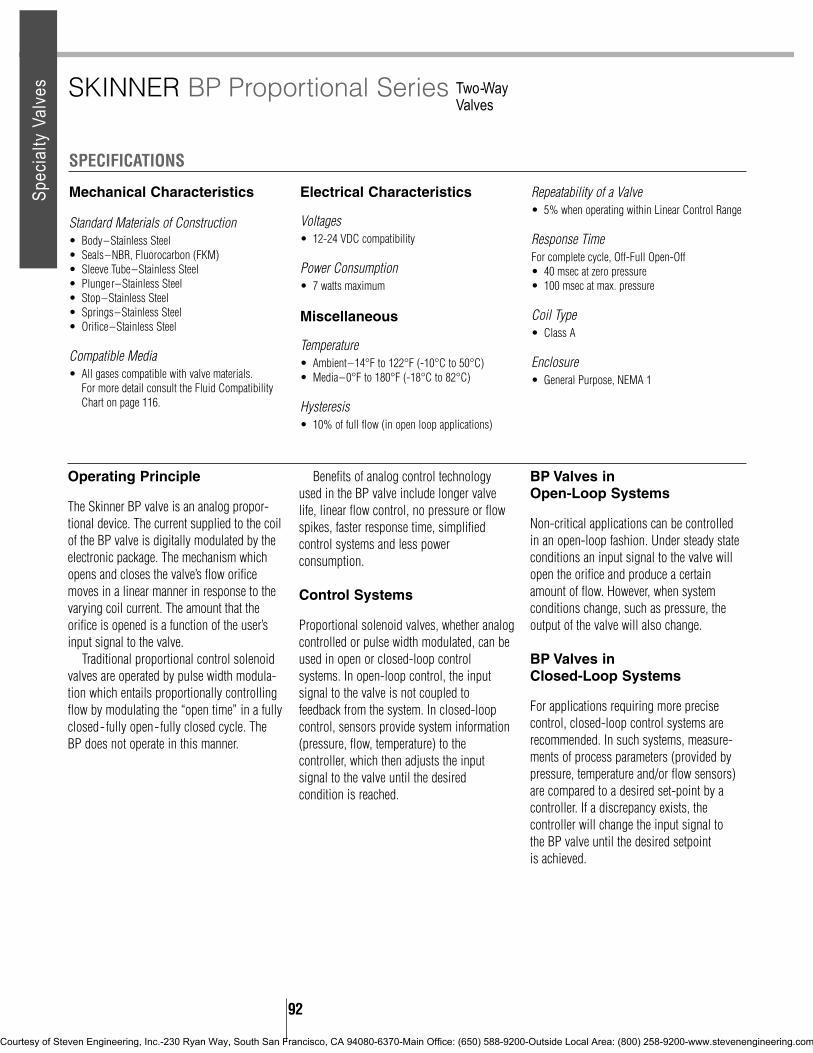
Mechanical Characteristics
Standard Materials of Construction• Body–Stainless Steel• Seals–NBR, Fluorocarbon (FKM)• Sleeve Tube–Stainless Steel• Plunger–Stainless Steel• Stop–Stainless Steel• Springs–Stainless Steel• Orifice–Stainless Steel
Compatible Media• All gases compatible with valve materials.
For more detail consult the Fluid CompatibilityChart on page 116.
Electrical Characteristics
Voltages• 12-24 VDC compatibility
Power Consumption• 7 watts maximum
Miscellaneous
Temperature• Ambient–14°F to 122°F (-10°C to 50°C)• Media–0°F to 180°F (-18°C to 82°C)
Hysteresis• 10% of full flow (in open loop applications)
Repeatability of a Valve• 5% when operating within Linear Control Range
Response TimeFor complete cycle, Off-Full Open-Off• 40 msec at zero pressure• 100 msec at max. pressure
Coil Type• Class A
Enclosure• General Purpose, NEMA 1
SPECIFICATIONS
SKINNER BP Proportional Series Two-Way Valves
Operating Principle
The Skinner BP valve is an analog propor-tional device. The current supplied to the coilof the BP valve is digitally modulated by theelectronic package. The mechanism whichopens and closes the valve’s flow orificemoves in a linear manner in response to thevarying coil current. The amount that theorifice is opened is a function of the user’sinput signal to the valve.
Traditional proportional control solenoidvalves are operated by pulse width modula-tion which entails proportionally controllingflow by modulating the “open time” in a fullyclosed-fully open-fully closed cycle. TheBP does not operate in this manner.
Benefits of analog control technologyused in the BP valve include longer valvelife, linear flow control, no pressure or flowspikes, faster response time, simplifiedcontrol systems and less powerconsumption.
Control Systems
Proportional solenoid valves, whether analogcontrolled or pulse width modulated, can beused in open or closed-loop controlsystems. In open-loop control, the inputsignal to the valve is not coupled tofeedback from the system. In closed-loopcontrol, sensors provide system information(pressure, flow, temperature) to thecontroller, which then adjusts the inputsignal to the valve until the desiredcondition is reached.
BP Valves in Open-Loop Systems
Non-critical applications can be controlledin an open-loop fashion. Under steady stateconditions an input signal to the valve willopen the orifice and produce a certainamount of flow. However, when systemconditions change, such as pressure, theoutput of the valve will also change.
BP Valves in Closed-Loop Systems
For applications requiring more precisecontrol, closed-loop control systems arerecommended. In such systems, measure-ments of process parameters (provided bypressure, temperature and/or flow sensors)are compared to a desired set-point by acontroller. If a discrepancy exists, thecontroller will change the input signal to the BP valve until the desired setpoint is achieved.
92
Spec
ialty
Val
ves
Courtesy of Steven Engineering, Inc.-230 Ryan Way, South San Francisco, CA 94080-6370-Main Office: (650) 588-9200-Outside Local Area: (800) 258-9200-www.stevenengineering.com

93
Note: Custom configurations and calibrations are available to suit your exact flow requirements. Forinformation consult the factory.
#66
DRAW
INGS
Two-WayValves
BP Proportional Series
BP VALVES–NORMALLY CLOSEDPipe Orifice Maximum Flow Ranges Catalog NumberSize Size Operating At Maximum 10 PSI Control Input Signal
(NPT) (inches) Pressure Operating Pressure Example Const.Cv (PSI) (SCCM) (SCCM) 0-2V 0-5V 0-10V 4-20mA Ref.
1/8” 1/32 0.02 200 0-50,000 0-8,000 BP2EV0001 BP2EV0012 BP2EV0013 BP2EV0029 66
1/8” 3/64 0.045 100 0-65,000 0-17,000 BP2EV0002 BP2EV0010 BP2EV0011 BP2EV0024 66
1/8” 1/16 0.08 60 0-75,000 0-30,000 BP2EV0003 BP2EV0005 BP2EV0009 BP2EV0020 66
1/8” 5/64 0.12 40 0-80,000 0-45,000 BP2EV0004 BP2EV0006 BP2EV0008 BP2EV0014 66
Spec
ialty
Val
ves
Courtesy of Steven Engineering, Inc.-230 Ryan Way, South San Francisco, CA 94080-6370-Main Office: (650) 588-9200-Outside Local Area: (800) 258-9200-www.stevenengineering.com

712712712732732732732732732
For hazardous and low-power power applications
Today, intrinsically safe systems andproducts are recommended, or in somecases compulsory, where the highest level ofprotection from explosion is required. Theyare also employed in applications thatrequire low power.
A hazardous (classified) location is wherefire or explosion hazards exist due to thepresence of flammable gases or vapors,flammable liquids, combustible dust, oreasily ignitable fibers or flyings.
Skinner Valve has long served industrywith innovative and safety related products.Our Intrinsically Safe solenoid valves haveapprovals for use in the United States andCanada in hazardous classifications forClasses I, II, III, Division 1 and 2, and in theUnited Kingdom for Division 0, 1 and 2. InEurope our valves are approved according toCENELEC standards. All countries in West-ern Europe now follow common (CENELEC)standards. All CENELEC member countriesshould recognize apparatus which have beentested and certified by any CENELECmember country.
What is an intrinsically safe system?An intrinsically safe system is most often anassembly of approved intrinsically safeapparatus, associated apparatus, andinterconnecting cables. Approved I.S.apparatus are devices that are incapable,during normal operation or under faultconditions, of causing explosive atmos-pheres to ignite by spark or thermal effect.Explosive atmospheres are mixtures offlammable or combustible material in air intheir most easily ignitable concentrations.
Solenoid valves are examples of I.S.apparatus and must be approved for use inspecific hazardous (classified) locations.Associated apparatus, such as safetybarriers, are devices which are not neces-sarily intrinsically safe themselves, butwhich are not necessarily intrinsically safethemselves, but which affect the energy inthe I.S. circuit and are relied upon tomaintain intrinsic safety.
How does intrinsic safety apply to solenoid valves?When related to solenoid valves, intrinsicsafety means that the coil’s current draw andresulting temperature is held to such a lowlevel (by an approved safety barrier) that thevalve no longer has the capability of ignitinga mixture of flammable or combustiblematerial, either during normal operation orunder fault conditions.
When designed into anintrinsically safe system,Skinner’s Intrinsically Safesolenoid valves provide a number of significantperformance advantages.
Low Power ConsumptionSkinner’s Intrinsically Safe valves are rated at 24VDC nominal, and are calibrated to operate at aminimum current draw as low as 29 milliamps(0.029 amps).
Low Temperature RiseSkinner Intrinsically Safe valve enclosures aredesigned to maintain a maximum outside surfacetemperature less than 85°C. This meets the T6classification assigned by Underwriters Laboratories Inc.
Variety of Mounting PossibilitiesSkinner Intrinsically Safe valves can be mounted inany position and still operate normally.
Media CompatibilityIntrinsically Safe Skinner valves in 2-wayconstructions are suitable for use with oil, air, water,and inert gases. Our 3- and 4-way valves aresuitable for use with air and inert gases only.
Wide Selection of OptionsA selection of coil enclosures including splice box,cable, 1/2” NPT conduit, and DIN coils are availablefor use with Skinner Intrinsically Safe valves.Additionally, some models are offered in manifoldmounted configurations.
Watertight ConstructionAll Intrinsically Safe Skinner coil enclosures areequivalent to NEMA 4 Watertight construction.
SKINNER Intrinsically Safe Series
SKINNER INTRINSICALLY SAFE SOLENOID VALVES
94
Spec
ialty
Val
ves
Courtesy of Steven Engineering, Inc.-230 Ryan Way, South San Francisco, CA 94080-6370-Main Office: (650) 588-9200-Outside Local Area: (800) 258-9200-www.stevenengineering.com

INTRINSICALLY SAFE SOLENOID VALVES–TWO-POSITIONGlobal Valve Operating Minimum Maximum Valve
Part Part Valve Port Size Orifice Materials Pressure Flow Rate Ambient Fluid Weight Const.Number Number Type NPTF Size Seal/Body Differential (PSI) Cv/SCFM* Temp. °F/°C Temp. °F/°C lbs. Ref.
21KBN2CV90 U121K0490 2W,NC 1/4” 3/64” FKM/Brass 0-150 0.04/1.2 +14/-10 165/75 0.44 7221KBN2EV90 U121K0890 2W,NC 1/4” 1.2mm FKM/Brass 0-100 0.06/1.75 +14/-10 165/75 0.44 7221KBN2GV90 U121K0690 2W,NC 1/4” 1.5mm FKM/Brass 0-75 0.11/2.8 +14/-10 165/75 0.44 7221HBN4UV90 U321H1590 2W,NC 1/2” 5/8” FKM, NBR/Brass 5-150 4.4/110 +14/-10 165/75 1.38 7321GBN53V90 U321G3690 2W,NC 3/4” 3/4” FKM, NBR/Brass 5-150 9.8/330 +14/-10 165/75 2.86 7421GBN64V90 U321G3790 2W,NC 1” 1” FKM, NBR/Brass 5-150 12.6/490 +14/-10 165/75 2.42 7421GBN76V90 U321G3890 2W,NC 1 1/4’ 1 1/4’ FKM, NBR/Brass 5-150 19.6/630 +14/-10 165/75 3.75 7421GBN88V90 U321G3990 2W,NC 1 1/2” 1 9/16” FKM, NBR/Brass 5-150 29.5/1100 +14/-10 165/75 5.30 7421GBN99V90 U321G4090 2W,NC 2” 1 9/16” FKM, NBR/Brass 5-150 39.2/1400 +14/-10 165/75 6.17 74
Mechanical Characteristics
Standard Materials of Construction• Body–Brass• Seals–FKM, NBR.
Compatible Media• Air, water and light oil.
Electrical Characteristics
Based on coil selected. See catalog pages 102-106for detailed electrical information.
Miscellaneous
For applications below freezing temperatures, valves must be degreased. Consult Skinner prior to ordering.
SPECIFICATIONS
95
#72
DRAW
INGS
#73
SKINNER Intrinsically Safe Series Two-Way Direct Acting and Pilot Operated Valves
* Measured at 90 PSI with a 15 PSI differential.
Spec
ialty
Val
ves
Note: Coil for illustrative purposes.
Courtesy of Steven Engineering, Inc.-230 Ryan Way, South San Francisco, CA 94080-6370-Main Office: (650) 588-9200-Outside Local Area: (800) 258-9200-www.stevenengineering.com

#74
Two-Way Direct Acting and Pilot Operated Valves
Intrinsically Safe Series
N
713171317131713171317131
713713171317331733
96
Spec
ialty
Val
ves
Valve A B C D E F G HIN MM IN MM IN MM IN MM IN MM IN MM NPT IN MM
U321G3690 3-15/16” 100 5-5/16” 135 2” 50 7/8” 23 2-23/64” 60 1-5/8” 41 3/4” 2-3/4” 70U321G3790 3-15/16” 100 5-5/16” 135 2” 50 7/8” 23 2-23/64” 60 1-5/8” 41 1” 2-3/4” 70U321G3890 4-11/32” 110 6-7/32” 158 2-5/32” 55 1-9/32” 33 2-7/8” 73 2-3/8” 60 1-1/4” 2-3/4” 70U321G3990 5-17/32” 140 6-7/32” 158 3” 75 1-9/32” 33 2-7/8” 73 2-3/8” 60 1-1/2” 3-1/16” 99U321G4090 5-29/32” 150 6-25/32” 172.5 3-5/32” 80 1-21/32” 41.5 3-7/64” 79 3” 75 2” 3-1/16” 99
Courtesy of Steven Engineering, Inc.-230 Ryan Way, South San Francisco, CA 94080-6370-Main Office: (650) 588-9200-Outside Local Area: (800) 258-9200-www.stevenengineering.com

Mechanical Characteristics
Standard Materials of Construction• Body–Brass, Stainless Steel or Aluminum• Seals–FKM, NBR.
Compatible Fluids• Air and inert gases.
Electrical Characteristics
• Based on coil selected. Valve U133X5196functions with coil part numbers 490860,482660, and 48333.,01 only. See catalog pages102-106 for detailed electrical information.
Miscellaneous
Sleeve Exhaust Adaptor• U21-004 must be ordered separately.
For applications below 32°F, valves must bedegreased. Consult Fluid Control Division prior toordering.
SPECIFICATIONS
SKINNER Intrinsically Safe Series Three-Way Direct Acting and Pilot Operated Valves
* Measured at 90 PSI with a 15 PSI differential. # Other diaphragm material available upon request.
Note: U133X5196 valves function with coils 490860, 482660 or 483330.01 only.
#75
DRAW
INGS
#76
INTRINSICALLY SAFE SOLENOID VALVES–TWO-POSITIONGlobal Valve Operating Minimum Maximum Valve
Part Part Valve Port Size Orifice Materials Pressure Flow Rate Ambient Fluid Weight Const.Number Number Type NPTF Size Seal/Body Differential (PSI) Cv/SCFM* Temp. °F/°C Temp. °F/°C lbs. Ref.
1KBN2CV90 U131K0490 3W, NC 1/4” 3/64” FKM/Brass 0-150 0.04/1.25 +14/-10 165/75 0.44 751KBN2EV90 U131K0890 3W, NC 1/4” 1.2mm FKM/Brass 0-100 0.06/1.75 +14/-10 165/75 0.44 751KBN2GV90 U131K0690 3W, NC 1/4” 1.5mm FKM/Brass 0-75 0.11/2.8 +14/-10 165/75 0.40 751VVN2CV90 U131V5490 3W, NC 1/4” 3/64” FKM/S.Steel(303) 0-150 0.04/1.25 +14/-10 165/75 0.50 761VVN2EV90 U131V5890 3W, NC 1/4” 1.2mm FKM/S.Steel(303) 0-100 0.06/1.75 +14/-10 165/75 0.53 761VVN2GV90 U131V5690 3W, NC 1/4” 1.5mm FKM/S.Steel(303) 0-75 0.11/2.8 +14/-10 165/75 0.53 76
- U133X5196 3W,U 1/4” 5mm NBR/S.Steel (316) 0-150 .63/24.5 +14/-10 165/75 1.81 771FBF4CV90 U131F4490 3W, NC Subbase 3/64” FKM/Brass 0-150 0.04/1.25 +14/-10 165/75 0.30 781FBNFGV90 U131F4890 3W, NC Subbase 1.2mm FKM/Brass 0-100 0.06/1.75 +14/-10 165/75 0.33 781FBNFEV90 U131F4690 3W, NC Subbase 1.5mm FKM/Brass 0-75 0.11/2.8 +14/-10 165/75 0.33 781BAN2KV90 U331B7490 3W, NC 1/4” 9/32” FKM, NBR/Aluminum 15-150 0.70/26 +14/-10 165/75 0.88 791LAV4TV90 U331L2190 3W, NC 1/2” 5/8” FKM, NBR/Aluminum 7-150 4/175 +14/-10 165/75 2.90 80
97
Spec
ialty
Val
ves
(1/8” BSPP)
Courtesy of Steven Engineering, Inc.-230 Ryan Way, South San Francisco, CA 94080-6370-Main Office: (650) 588-9200-Outside Local Area: (800) 258-9200-www.stevenengineering.com

Manifold ComponentsDescription Part No.Manifold Subbases for 2 valves 486162Manifold Subbases for 3 valves 486163Manifold Subbases for 5 valves 486164Connection Nipples 4857250-Ring 485730Screw-M4X12 486194
#78A
#79 #80
Three-Way Direct Acting and Pilot Operated Valves
Intrinsically Safe Series
Note: Only coils 490880, 483580 and 483960 can be used with manifolds.Manifold subbases are anodized aluminum.
#78
Required ComponentsQuantity of Connection
Valves Subbases Nipples O-Rings Screws2 1-486162 NR NR 8-4861943 1-486163 NR NR 12-4861944 2-486162 1-485725 2-485730 16-4861945 1-486164 NR NR 20-4861946 2-486163 1-485725 2-485730 24-4861947 1-486162 1-485725 2-485730 28-486194
1-4861648 1-486163 1-485725 2-485730 32-486194
1-4861649 1-486162 2-485725 4-485730 36-486194
1-48616410 2-486164 1-485725 2-485730 40-486194
98
Spec
ialty
Val
ves
#77
Courtesy of Steven Engineering, Inc.-230 Ryan Way, South San Francisco, CA 94080-6370-Main Office: (650) 588-9200-Outside Local Area: (800) 258-9200-www.stevenengineering.com

INTRINSICALLY SAFE SOLENOID VALVES–THREE-WAY, TWO-POSITION, UNIVERSAL, MANUAL RESETValve Operating Minimum Maximum Valve
Part Valve Port Size Orifice Materials Pressure Flow Rate Ambient Fluid Weight Const.Number Type NPTF Size Seal/Body Differential (PSI) Cv/SCFM* Temp. °F/°C Temp. °F/°C lbs. Ref
U033X5156 3W,U 1/4” 5mm FKM/S.Steel 0-150 .63/24.5 -13/-25 165/75 1.81 81
Mechanical Characteristics
Standard Materials of Construction• Body–Brass, Stainless Steel• Seals–NBR, FKM
Compatible Fluids• Air and inert gases.
Electrical Characteristics
• Based on coil selected. the Quick Exhaust valvefunctions with coil numbers 490860, 482660 and483330.01 only. See catalog page 106 fordetailed electrical information.
Miscellaneous
Safe body working pressure is 1500 PSI (QuickExhaust) and 725 PSI (Manual Reset).
SPECIFICATIONS
SKINNER Intrinsically Safe Series Special Purpose Three-Way Quick Exhaust and Manual Reset Valves
* Measured at 90 PSI with a 15 PSI differential. Safe body working pressure 725 PSI. Note: This valve must be used with I.S. coils 492335 or 490860 only
* Measured at 90 PSI with a 15 PSI differential. Safe body working pressure 1500 PSI. Note: This valve functions with coils 490860, 482660 or 483330.01 only.
#81
DRAW
INGS
INTRINSICALLY SAFE SOLENOID VALVES–THREE-WAY, TWO-POSITION, QUICK EXHAUSTGlobal Valve Operating Flow Rate Minimum Maximum Valve
Part Part Valve Port Size Orifice Size Materials Pressure Cv SCFM* Ambient Fluid Weight Const.Number Number Type NPTF P E Seal/Body Differential P E P E Temp. °F/°C Temp. °F/°C lbs. Ref.
- U131E0391 3W, NC 1/4” 3/32 1/4 FKM, NBR/ 1.5-105 0.29 1.1 8 39 +14/-10 165/75 1.32 82Brass
#82
99
Spec
ialty
Val
ves
Courtesy of Steven Engineering, Inc.-230 Ryan Way, South San Francisco, CA 94080-6370-Main Office: (650) 588-9200-Outside Local Area: (800) 258-9200-www.stevenengineering.com

Mechanical Characteristics
Standard Materials of Construction• Body–Aluminum• Seals–FKM, NBR.
Compatible Fluids• Air and inert gases.
Electrical Characteristics
• Based on coil selected. See catalog pages 102-106 for detailed electrical information.
SPECIFICATIONS
SKINNER Intrinsically Safe Series Four-Way Two-Position Valves
* Measured at 90 PSI with a 15 PSI differential. # Other diaphragm material available upon request.
#83
DRAW
INGS
#84
INTRINSICALLY SAFE SOLENOID VALVES–TWO-POSITIONGlobal Valve Operating Minimum Maximum Valve
Part Part Valve Port Size Orifice Materials Pressure Flow Rate Ambient Fluid Weight Const.Number Number Type NPTF Size Seal/Body Differential (PSI) Cv/SCFM* Temp. °F/°C Temp. °F/°C lbs. Ref.
41BAN2JV90 U341B3490 4-way 1/4” 1/4” FKM, NBR/4-ported Aluminum 15-150 0.7/24 +14/-10 165/75 1.28 83
41LAV4TV90 U341L2190 4-way 1/2” 9/16” FKM, NBR/5-ported Aluminum 7-150 4/175 +14/-10 165/75 3.75 84
41LAV62V90 U341L4190 4-way FKM, NBR/5 ported 1” BSP 1” Aluminum 15-150 10.5/390 +14/-10 165/75 9.03 85
47LMN2NV90 U347L1190 4-way NBR/5-ported 1/4” 5/16” Zamak (Zinc alloy) 15-150 1.4/54 +14/-10 165/75 2.04 86
2-solenoid
100
Spec
ialty
Val
ves
Courtesy of Steven Engineering, Inc.-230 Ryan Way, South San Francisco, CA 94080-6370-Main Office: (650) 588-9200-Outside Local Area: (800) 258-9200-www.stevenengineering.com

SKINNER Intrinsically Safe Series Four-Way Two-Position Valves
#85 #86
101
Spec
ialty
Val
ves
Courtesy of Steven Engineering, Inc.-230 Ryan Way, South San Francisco, CA 94080-6370-Main Office: (650) 588-9200-Outside Local Area: (800) 258-9200-www.stevenengineering.com

102
Intrinsically Safe Series
IMPORTANT: The intrinsically safe supplycircuit should have enough capacity in allenvironmental and system conditions to insuredelivery of at least the minimum specifiedoperating current of the coil. Be sure to includethe internal coil resistance and the bridgerectifier resistance (where applicable) whencalculating circuit parameters.
Splice Box Enclosure with Strain Relief EgressSpecifications
Protection Class• IP 65 according to DIN 40050 and IEC 529
standards. Equivalent to NEMA 4 Watertight.
Construction• Polyamid with fiberglass enclosure and cover.
Electrical Entry and Connections• Cable entry through a blue cable gland M20 X
1.5. Screw terminals for leads 3 x 1.5mm2.Additional ground connection possible withexternal screw terminal.
Enclosure• Coil, printed circuit and other parts for I.S.
specifications are completely encapsulated withinthe enclosure using epoxy material.
Dielectric Strength• Greater than 500 V rms
Bridge Rectifier Resistance• Less than 50 ohms at 29mA
Coil Internal Resistance• 295 ohms at 20°C
Voltage• 24 VDC nominal
Minimum Operating Current• 29 milliamps
Coil Temperature Rise• Less than 5°C
Maximum Enclosure Temperature• <85°C (corresponding to T6 class) according to
CENELEC-EN 50014.
Ambient Temperature• -13°F to + 149°F (-25°C to +65°C)
F.M. Entity Parameters• Vmax = 30 volts• Imax = 100 mA• Ci = O• Li = 0 mH
Options• 1/2” NPT Conduit Hub Adaptor. Order part
number U22-001.
#67
DRAW
INGS
INTRINSICALLY SAFE COIL AND ENCLOSURE INFORMATION
Reference Number Approvals Classification
490885 LCIE/FM/CSA Class I, Div. 1, Grps A,B,C,D, Class II, Div. 1,
Grps E,F,G
488650.01 LCIE 02 ATEX 6024X EEx ia IIC T6
488650.03 AUS EX 137X Ex ia IIC T6Elec
trica
l Par
ts
Spec
ialty
Val
ves
Courtesy of Steven Engineering, Inc.-230 Ryan Way, South San Francisco, CA 94080-6370-Main Office: (650) 588-9200-Outside Local Area: (800) 258-9200-www.stevenengineering.com

* Note: According to CENELEC
#68
DRAW
INGS
Potted Lead Wire Coil with Strain Relief EgressSpecifications
Protection Class• IP 67 according to DIN 40050 and IEC 529
standards. Equivalent to NEMA 4 Watertight.
Construction• Epoxy coated metal enclosure and cover.
Electrical Entry and Connections• Fixed and potted two core (2 x 1mm2) blue
connection cable of 2m length. Other cablelengths on request. Entry cable gland pg 11(18.6mm) (DIN 46320). Additional groundconnection possible with external screw terminal.
Enclosure• Coil, welded lead connections, printed circuit
and other parts for I.S. specifications arecompletely encapsulated within the enclosureusing epoxy material.
Dielectric Strength• Greater than 500 V rms
Bridge Rectifier Resistance•Less than 50 ohms at 29mA
Coil Internal Resistance• 295 ohms at 20°C
Voltage• 24 VDC nominal
Minimum Operating Current• 29 milliamps
Coil Temperature Rise• Less than 5°C
Maximum Enclosure Temperature• <85°C (corresponding to T6 class) according to
CENELEC-EN 50014.
Ambient Temperature• -40°F to + 149°F (-40°C to +65°C)
F.M. Entity Parameters• Vmax = 30 volts• Imax = 100 mA• Ci = O• Li = 0 mH
Options• 1/2” NPT Conduit Hub Adaptor. Order part
number U22-003.
Intrinsically Safe Series
Reference Number Approvals Classification
490890 LCIE/FM/CSA Class I, Div. 1, Grps A,B,C,D(VZ1300) Class II, Div. 1, Grps E,F,G
488660.01 LCIE 02 ATEX 6024X EEx ia IIC T6
488660.03 AUS EX 137X Ex ia IIC T6
Elec
trica
l Par
ts
103
Spec
ialty
Val
ves
Courtesy of Steven Engineering, Inc.-230 Ryan Way, South San Francisco, CA 94080-6370-Main Office: (650) 588-9200-Outside Local Area: (800) 258-9200-www.stevenengineering.com

Potted Coil with DINConnection and DIN PlugAdaptor Specifications
Protection Class• IP 65 according to DIN 40050 and IEC 529
standards (with DIN plug). Equivalent to NEMA 4Watertight.
Construction• Epoxy coated metal enclosure and cover.
Electrical Entry and Connections• Blue “DIN” standard plug interface and 3-pin
AMP plug (DIN 43650 type A) with blue pg 9gland (15.2mm)
Enclosure• Coil, printed circuit and other parts for I.S.
specifications are completely encapsulated withinthe enclosure using epoxy material.
Dielectric Strength• Greater than 500 V rms
Bridge Rectifier Resistance• Less than 50 ohms at 29mA
Coil Internal Resistance• 295 ohms at 20°C
Voltage• 24 VDC nominal
Minimum Operating Current• 29 milliamps
Coil Temperature Rise• Less than 5°C
Maximum Enclosure Temperature• <85°C (corresponding to T6 class) according to
CENELEC-EN 50014.
Ambient Temperature• 13°F to + 149°F (-25°C to +65°C)
F.M. Entity Parameters• Vmax = 30 volts• Imax = 100 mA• Ci = O• Li = 0 mH
Options• 1/2” NPT DIN Plug Adaptor. Order part number
U27-001.
#69
DRAW
INGS
Intrinsically Safe Series
Reference Number Approvals Classification
490895 LCIE/FM/CSA Class I, Div. 1, Grps A,B,C,D(VZ2000) Class II, Div. 1, Grps E,F,G
488670.01 LCIE 20 ATEX 6024X EEx ia IIC T6
Elec
trica
l Par
ts
104
Spec
ialty
Val
ves
Courtesy of Steven Engineering, Inc.-230 Ryan Way, South San Francisco, CA 94080-6370-Main Office: (650) 588-9200-Outside Local Area: (800) 258-9200-www.stevenengineering.com

#70
DRAW
INGS
32mm DIN Coil and PlugAdaptor Specifications
Protection Class• IP 65 according to DIN 40050 and IEC 529
standards (with DIN plug). Equivalent to NEMA 4Watertight.
Construction• Fully encapsulated assembly comprising a coil,
integral magnetic iron path, three diodes circuitand DIN plug connection. The encapsulationprovides an effective compact enclosure offeringfull protection against dust, oil, water etc.
Electrical Entry and Connections• The coil is connected with a 3-pin plug pg 9
gland (part number 486586) according to DIN43650 type A.
Dielectric Strength• Greater than 500 V rms
Coil Internal Resistance• 340 ohms at 20°C
Voltage• 24 VDC nominal
Minimum Operating Current• 35 milliamps
Coil Temperature Rise• Less than 5°C
Maximum Enclosure Temperature• <85°C (corresponding to T6 class) according to
CENELEC-EN 50014.
Ambient Temperature• 13°F to + 131°F (-25°C to +55°C)
F.M. Entity Parameters• Vmax = 30 volts• Imax = 100 mA• Ci = O• Li = 0 mH
Options• 1/2” NPT DIN Plug Adaptor. Order part number
U27-001.
Intrinsically Safe Series
Reference Number Approvals Classification
490880 With Din Plug* Class I, Div. 1, Grps A,B,C,DLCIE/FM/CSA PEN Class II, Div. 1, Grps E,F,G
483580.01 Without DIN Plug,** EEx ib IIC T6
483960.01 With DIN plug,** EEx ia IIC T6
Elec
trica
l Par
ts
105
Spec
ialty
Val
ves
* LCIE/FM/CSA PENDING** LCIE 20 ATEX 6065 X
Courtesy of Steven Engineering, Inc.-230 Ryan Way, South San Francisco, CA 94080-6370-Main Office: (650) 588-9200-Outside Local Area: (800) 258-9200-www.stevenengineering.com

Acceptable Barriers Include:
MTL 3022MTL 779STAHL 9001/01-280/110/10STAHL 9001/01-280/100/10STAHL 9001/01-280/165/10STAHL 9001/03-280/000/00STAHL 9002/13-280/100/04STAHL 9002/13-280/110/00 #71
DRAW
INGS
Splice Box Enclosure withBooster Circuit and StrainRelief Egress Specifications
Protection Class• IP 65 according to DIN 40050 and IEC 529
standards. Equivalent to NEMA 4 Watertight.
Construction• Polyamid with fiberglass enclosure and cover.
Electrical Entry and Connections• Screw terminals within terminal box. Cable
connection through M20x1.5 cable gland.Additional ground connection possible withexternal ground terminal.
Enclosure• Coil, printed circuit and other parts for I.S.
specifications are completely encapsulated withinthe enclosure using epoxy material.
Booster Circuits• The electronic booster circuit consists of
capacitor, diodes, thyristor and Zener diode.
Voltage• Nominal: 24 VDC nominal• Maximum: 28 VDC• Minimum at Attraction: 21.6 VDC** Circuit design must ensure that at least 21.6
VDC is available at the solenoid for properoperation.
Minimum Holding Current• 60 mA
Coil Temperature Rise• Less than 5°C
Maximum Enclosure Temperature• <85°C (corresponding to T6 class) according to
CENELEC-EN 50014.
Ambient Temperature• 13°F to + 140°F (-25°C to +60°C)
Required Time Delay for Renewed ValveActuation after Booster Discharge• Approximately 1 second at nominal voltage
Duty Cycle• 100% solenoid duty
Options• 1/2” NPT Conduit Hub Adaptor. Order part
number U22-001.
Intrinsically Safe Series
Reference Number Approvals Classification
490860 FM CSA Class I, Div. 1, Grps A,B,C,DClass II, Div. 1, Grps E,F,G
482660 LCIE 02 ATEX 6024X EEx ib IIB T6
483330.01 LCIE 02 ATEX 6024X EEx ia IIC T6
Elec
trica
l Par
ts
* Note: According to CENELEC
106
Spec
ialty
Val
ves
Courtesy of Steven Engineering, Inc.-230 Ryan Way, South San Francisco, CA 94080-6370-Main Office: (650) 588-9200-Outside Local Area: (800) 258-9200-www.stevenengineering.com

107
SKINNER Intrinsically Safe Series Four-Way Two-Position Valves
HAZARDOUS CLASSIFICATIONS (CLASS)
CLASS IGASSES OR VAPORS
CLASS IIDUST
CLASS IIIFIBERS
Division 1Hazardous vapors present
Group AAcetylene
Group BHydrogen, etc.
Group CEther, UDMH, ethylene, etc.
Group DAcetone, hydro-carbons,acetates, alcohols, etc.
Group EMetal: aluminum,magnesium, etc.
Group FCarbon black, coal,
coke dust, etc.
Group GFlour, starch, grain, andorganic food stuffs, etc.
No GroupsTextiles, wood, synthetic
fibers
Division 2Hazardous vapors contained
but may be present
Division 1Air suspended
Division 2Surface accumulatednon-air suspended
Division 1Handled, manufactured
or used
Division 2Handled and stored
Typical Gasses in UK and CENELEC US NationalAtmosphere (BS5501: Part 1 Electrical
Class I EN 50 014) Code Group
Maximum Surface US StandardTemperature (U.L.) CENELEC
Description US CENELECTypical Dusts in UK and CENELEC US NationalAtmosphere (BS5501: Part 1 Electrical
Class I EN 50 014) Code Group
Spec
ialty
Val
ves
Courtesy of Steven Engineering, Inc.-230 Ryan Way, South San Francisco, CA 94080-6370-Main Office: (650) 588-9200-Outside Local Area: (800) 258-9200-www.stevenengineering.com

Mechanical Characteristics
Standard Materials of Construction• Body–Stainless Steel (430F)• Seals–Metal• Flange Seal–NBR• Sleeve–Stainless Steel (304)• Plunger–Stainless Steel (430FR)• Stop–Stainless Steel (430FR)• Springs-Stainless Steel (18-8)• Shading Ring–Copper (AC only)• Spool–Stainless Steel (17-4PH)
Compatible Fluids• Hydraulic Fluids.
Product Description
Skinner 2-way and 3-way A-10 Series valves aredesigned for use in high-pressure systemsapplications up to 3000 PSI. In addition to beingavailable in pipe mounting configurations, A-10valves are available in several custom mountingconfigurations including manifold, flange, and cageor cartridge mounted products.
Electrical Characteristics
Voltages• DC–12, 24, 120• AC–24/60, 120/60, 240/60
Power Consumption• 14 watts DC• 21 watts AC
Miscellaneous
Operating Speed• Up to 300 cycles per minute.
Response Time• AC–Approximately 4-8 milliseconds to open orcccclose.• DC–Approximately 15-30 milliseconds to open,
15-25 milliseconds to close.
Leakage• Internal–Maximum of 295cc/min. at 3000 PSI
and 70°F with Mil-H-5606 oil.• External–None.
Valve Construction Alternatives
Coil Type• Class B molded leaded
Enclosure Type• 1/2” NPT conduit enclosure
Flow Limits• The spool in A10 Series valves will fail to shift
when flow exceeds the maximum rated value.Each catalog listing indicates the flow andpressure drop for which these valves will operatewithout malfunction. The static pressure listed foreach valve will not adversely affect valveoperation as long as the rated flows and pressuredifferentials are not exceeded. The maximumflows (GPM) and pressure differentials (PSI) arebased on Mil-H-5606A hydraulic oil at 80°F.
Mounting• Manifold, flange and cage types available.
Consult factory for details.
SPECIFICATIONS
SKINNER A-10 Series High Pressure Two- and Three-Way Direct Acting Hydraulic Valves
TWO WAY TYPE A11 AND A116 STAINLESS STEEL VALVES–NORMALLY OPENNPT Effective Static Pressure Rating (PSI) Max. Pressure Maximum Class B Molded CoilPipe Orifice Average Differential Flow Inlet Outlet 1/2” NPT Conduit Const.Size Diameter Cv Factor AC DC (PSI) (GPM) Port Port Enclosure Ref.
1/8” 3/32 0.15 3000 3000 9 3 2 A11LB13002 1343/32 0.15 3000 3000 9 3 2 A116LB13001 134
TWO WAY TYPE A12 AND A126 STAINLESS STEEL VALVES–NORMALLY CLOSEDNPT Effective Static Pressure Rating (PSI) Max. Pressure Maximum Class B Molded CoilPipe Orifice Average Differential Flow Inlet Outlet 1/2” NPT Conduit Const.Size Diameter Cv Factor AC DC (PSI) (GPM) Port Port Enclosure Ref.
1/8” 3/32 0.15 3000 3000 8.5 1 2 A12LB13002 1343/32 0.15 3000 3000 8.5 1 2 A126LB13001 134
108
Spec
ialty
Val
ves
Courtesy of Steven Engineering, Inc.-230 Ryan Way, South San Francisco, CA 94080-6370-Main Office: (650) 588-9200-Outside Local Area: (800) 258-9200-www.stevenengineering.com

109
#87
High Pressure Three-WayDirect Acting Hydraulic Valves
A-10 Series
#134
THREE WAY TYPE A16 AND A166 STAINLESS STEEL VALVES–DIRECTIONAL CONTROLNPT Effective Static Pressure Rating (PSI) Max. Pressure Maximum Class B Molded CoilPipe Orifice Average Differential Flow Inlet Outlet 1/2” NPT Conduit Const.Size Diameter Cv Factor AC DC (PSI) (GPM) Port Port Enclosure Ref.
1/8” 3/32 0.15 3000 2000 7 2 3 A16LB13002 873/32 0.15 3000 2000 7 2 1 A16LB13002 873/32 0.15 3000 2000 7 2 3 A166LB13001 873/32 0.15 3000 2000 7 2 1 A166LB13001 87
THREE WAY TYPE A13, A136 STAINLESS STEEL VALVES–NORMALLY CLOSEDNPT Effective Static Pressure Rating (PSI) Max. Pressure Maximum Class B Molded CoilPipe Orifice Average Differential Flow Inlet Outlet 1/2” NPT Conduit Const.Size Diameter Cv Factor AC DC (PSI) (GPM) Port Port Enclosure Ref.
1/8” 3/32 0.15 3000 1000 5.7 1 2 A13LB13002 873/32 0.15 3000 2000 7 2 3 A13LB13002 873/32 0.15 3000 1000 5.7 1 2 A136LB13001 873/32 0.15 3000 2000 7 2 3 A136LB13001 87
THREE WAY TYPE A15 AND A156 STAINLESS STEEL VALVES–NORMALLY OPENNPT Effective Static Pressure Rating (PSI) Max. Pressure Maximum Class B Molded CoilPipe Orifice Average Differential Flow Inlet Outlet 1/2” NPT Conduit Const.Size Diameter Cv Factor AC DC (PSI) (GPM) Port Port Enclosure Ref.
1/8” 3/32 0.15 3000 3000 9 3 2 A15LB13002 873/32 0.15 3000 3000 8.5 2 1 A15LB13002 873/32 0.15 3000 3000 9 3 2 A156LB13001 873/32 0.15 3000 3000 8.5 2 1 A156LB13001 87
Port Identification:A13 A15 A161-IN Exhaust NC
2-Cylinder Cylinder IN3-Exhaust IN NO
Port Identification:A11 A12
1-Plugged 1-IN2-OUT 2-OUT3-IN 3-Plugged
A13
A15
A16
A11
A12
NORMALLY OPEN
NORMALLY CLOSED
Spec
ialty
Val
ves
Courtesy of Steven Engineering, Inc.-230 Ryan Way, South San Francisco, CA 94080-6370-Main Office: (650) 588-9200-Outside Local Area: (800) 258-9200-www.stevenengineering.com

Product Description
MB Series valves are designed for the actuation ofsmall air cylinders and clamps, and are suited forapplications requiring low air flow.
The valves are direct acting, multipurpose valveswith all ports in the body. The valve body is moldedfrom plastic, while the internal parts are nylon, poly-ester and stainless steel. The valves will operate atup to 150 PSI, consuming only 4 watts per coil onAC operation, 5 watts per coil on DC.
Functional design flexibility is assured given thewide variety of available valve configurations. Thelisted accessories enable the user to customize MBSeries valves as 2-way normally open or normallyclosed by plugging one port; 3-way normally open,normally closed or directional control; and 4-waynormally closed-normally open, normally open-normally open, and normally closed-normallyclosed.
Mechanical Characteristics
Standard Materials of Construction• Body–Plastic• Seals–NBR• Sleeve–Stainless Steel (304)• Plunger–Stainless Steel (430FR)• Stop–Stainless Steel (430FR)• Springs—Stainless Steel (17-7PH)• Shading Ring–Copper (AC valves only)• Manifold Bases–Zinc
Compatible Media• Lubricated Air, Non-Lubricated Air, and Inert
Gases compatible with materials of construction.
Electrical Characteristics
Voltages• DC–12, 24, 120• AC–24/60, 120/60, 240/60
Power Consumption• 4 watts AC per coil• 5 watts DC per coil
Miscellaneous
Operating Speed• Up to 1000 cycles per minute.
Response Time• AC–Approximately 3-12 milliseconds to open,
5-16 milliseconds to close.• DC–Approximately 8-14 milliseconds to open,
5-15 milliseconds to close.
Leakage• Internal–Maximum 3 SCCM at 150 PSI.• External–None.
Standard Valve Construction
Coil Type• Class A taped with lead
Enclosure Type• Slotted enclosure for leaded coils.
SPECIFICATIONS
SKINNER MB Series Three-Way Direct Acting Valves
DIRECT ACTING THREE-WAY VALVES AND FOUR–WAY VALVE ASSEMBLIESOrifice Diameter Cv Factor Operating Pressure (PSI) Wattage Class A Taped Const.
Pipe Size NC Port NO Port NC Port NO Port Minimum Maximum AC DC Leaded Coil Ref.
#10-32 Ports 3/64 3/64 0.032 0.028 0 150 4 5 MBD002 88Manifold Mounted 3/64 3/64 0.032 0.028 0 150 4 5 MBD005 88
1/8 NPT 4 Way Assembly 3/64 3/64 0.032 0.028 0 150 8 10 MBD009 89
110
Spec
ialty
Val
ves
Courtesy of Steven Engineering, Inc.-230 Ryan Way, South San Francisco, CA 94080-6370-Main Office: (650) 588-9200-Outside Local Area: (800) 258-9200-www.stevenengineering.com

Ordering Instructions forMultiple Station Manifolds
Step 1: Determine the number of valvestations required. This will equal the numberof subbase valves to order (MBD005).
Step 2: Select the combination of two-and three-station manifolds that sum toequal the number of valve stations required(i.e. five stations total = one three-stationand one two-station manifold).
Step 3: Choose the accessory kitsrequired to complete the system anddetermine if you want the valves assembledto the manifolds at the factory.
Step 4: Specify the required voltage.
Example:1) You have selected a valve
which is to be manifolded.2) Your system requires a five-
station manifold (i.e. onethree-station manifoldattached to one two-stationmanifold).
3) You require the manifoldbases and an interface kit.You decide to assemble thevalves and manifolds. If theywere to be assembled by thefactory, there would be aprice-add.
4) Your system is 120/60 wattsAC: Your order should read:
5-MBD005, 120/601-MB-60-S0011-MB-60-S0021-MB-60-S0031-MB-60-S0051-MB-60-S006
111
#88
DRAW
INGS
#90
#89
Three-Way Direct Acting Valves
MB Series
Accessories Contents Part Number
2-Station Manifold Base Kit 4 Pipe plugs MB-60-S001(for mounting 2 valves) 4 No. 5 self tapping screws
3-Station Manifold Base Kit 5 Pipe plugs MB-60-S002(for mounting 3 valves) 6 No. 5 self tapping screws
Manifold Interface Kit 1 No. 8 screw MB-60-S003(connects 2 manifold bases) 2 ”O” rings
Manifold Blank Station Kit 1 Plate MB-60-S004(for sealing an unused station) 2 ”O” rings
2 Screws
2-Station Manifold Base 1 MB-01-003 manifold blockconst. ref. 90 2 V1-31-254 nuts assembled MB-60-S005
3-Station Manifold Base 1 MB-01-004 manifold blockconst. ref. 90 2 V1-31-254 nuts assembled MB-60-S006
Valve
Acc
esso
ries
Port Identification:1-NC/ 2-Common/ 3-NO
Port Identification:1-IN/ 2-Cylinder/ 3-Exhaust
Spec
ialty
Val
ves
Courtesy of Steven Engineering, Inc.-230 Ryan Way, South San Francisco, CA 94080-6370-Main Office: (650) 588-9200-Outside Local Area: (800) 258-9200-www.stevenengineering.com

112
Fluid• Lubricated or non-lubricated air and neutral
gases recommended filtration: 25-50u
Temperature Range• Ambient– 10°F (0 to 50°C)• Fluid–10°F (0 to 50°C)
Inlet Pressure Range• 15 to 175 PSI (1 to 12 bar). The inlet pressure
must always be at least 15 PSI above theregulated pressure value.
Outlet Pressure Range• 3 to 150 PSI (0.2 to 10 bar)
Hysteresis• 1.5 PSI (-100 mbar). Factory set up.
Linearity• 1% f.s.o.
Air Consumption at Constant Control Signal• 0
Voltage• 24 VDC + 15% (Max. ripple 1 V)
Power Consumption• Max. 6 W with 24 VDC and constant changes of
the control signal; <1W without change ofcontrol signal.
Control Signal• U=Analog 0-10V Impedance:10k• I=Analog 4-20 mA Impedance:0.5k
Outlet Sensor Signal• A) Proportional pressure outlet signal 0-10 V
from integrated sensor (recommended loadresistance 0.5k )
• B) Proportional pressure outlet signal 4020 mAfrom integrated sensor (recommended loadresistance 0.5 k )
• C) “Alarm” output signal 0/24 V with adjustabletriggering level. (Difference between controlsignal and sensor pressure signal). (Imax = 40 mA)- Factory set-up: Diff. signal = + 0.8 V to + 1 V- Possible set-ip: Diff. signal = + 0.1 V to + 5 VTo neutralize the alarm output signal during thecontrol signal changes, the use of a synchro-nized time lag relay is required.
Indicative Response Time• With a volume of 330 cm3 at the outlet of the
regulator.-Filling: 29 to 72 PSI (2 to 4 bar) 29 to 116 PSI (2 to 8 bar)-Step Response: ~60 ms ~120 ms-Emptying: 72 to 29 PSI (4 to 2 bar) 116 to 29 PSI (8 to 2 bar)-Step Response: ~70 ms ~130 ms
Safety Position• In case of control failure or if it is less than 1%
of its full scale value, the regulated pressuredrops automatically to 0 bar (atmosphericpressure). In case of voltage supply failure, theregulated pressure will be kept constant (witheventual discrepancy due to loss of pressure inthe servo-chamber).
Electrical Connection• 4 Screw terminals under the protection cover
with Pg 13.5 cable gland or through DIN 43651connector (6 P+E).
Life Expectancy• >50 Million changes of control signal steps.
NOTE: It is compulsory to set the control signalat 0 V or 4 mA each time the air pressure supplyis turned off (during the night or weekend).When the air pressure supply cannot be fullyexhausted, it is necessary to assure that thedeviation between the control value and the inletpressure remains smaller than 15 PSI (1 bar).
Mounting position• Indifferent (recommended position: upright;
electronic part on top).
Resistance to Vibration• 30 g in all directions
Degree of Protection• IP 65 (Equivalent to NEMA 4).
External Sensors• All pressure sensors with the following charac-
teristics are compatible with the EP-transducer.-Sensitivity: 15 PSI (0.5 V/bar) up to 15 PSI (10V/bar)
-Zero Offset: 15 PSI (-3 V/bar) to 15 PSI (10V/bar)
Assembly• Silicone free
Electromagnetic Compatibility• In accordance with IEC 801-4 part 4 standards.
Typical Applications• Paint spraying equipment• Robotic welding• Brake and clutch control
SPECIFICATIONS
EPP3 Electropneumatic Pressure Regulator
Entry option forExternal Sensor Signal Outlet Signal Option Electrical Connection
WithPressure Integrated Feedback Signal 0-10 V 0-10 V DIN 43651 Cable Gland
Range Connection Pressure(PSI) NPT Sensor 0-10 V 4-20 mA Without 4-20 mA 0/24 Alarm Connector Pg 13.5
EPP3J0 21 U/1 100 10 150 1/4 x x x21 U/1 600 10 150 1/4 x x x21 U/1 700 10 150 1/4 x x x
EPP3J0 23 U/1 130 10 150 1/4 x x x24 U/1 130 10 150 1/4 x x x
EPP3J0 41 U/1 100 10 150 1/2 x x x41 U/1 600 10 150 1/2 x x x41 U/1 700 10 150 1/2 x x x
EPP3J0 43 U/1 130 10 150 1/2 x x x44 U/1 130 10 150 1/2 x x x
SUMMARY OF TYPES
Courtesy of Steven Engineering, Inc.-230 Ryan Way, South San Francisco, CA 94080-6370-Main Office: (650) 588-9200-Outside Local Area: (800) 258-9200-www.stevenengineering.com

113
Courtesy of Steven Engineering, Inc.-230 Ryan Way, South San Francisco, CA 94080-6370-Main Office: (650) 588-9200-Outside Local Area: (800) 258-9200-www.stevenengineering.com

114
TechnicalInformationIntroduction
Solenoid valves are highly engineered productswhich can be utilized in many diverse and uniquefluid system applications. In addition to operationalfunctionality, selecting the best product for a givenapplication must also consider safety, reliability,media compatibility and suitability for the operatingenvironment. This section provides a brief overviewof the components and functional varieties ofsolenoid valves available from Fluid ControlDivision. A more detailed and complete discussionon solenoid valve technology is provided in theSkinner Valve Technical Reference Manual.
General Information
Valve Construction and Basic OperationA solenoid valve is operated by opening or closingan orifice in the valve body which permits orprevents flow through the valve. The orifice isopened or closed through the use of a plunger thatis raised and lowered within a sleeve tube byenergizing a solenoid. The bottom and /or top of theplunger contain soft elastomeric seals, which closeoff the orifice in the body or the stop respectively.
The solenoid assembly consists of a coil, plungerand sleeve assembly. In a normally closed valve aplunger return spring holds the plunger against theorifice, preventing flow through the valve. Whencurrent flows through the coil, a magnetic field isproduced which turns the stop into an electro-magnet that attracts the magnetic plunger. Thisaction compresses the return spring, allows thebody orifice to open and permits fluid to flow
through the valve.Effective operation of a solenoid valve is
dependent upon the efficiency of the magneticcircuit through which the flux travels. If the fluxpath is designed with a high level of magneticefficiency, (i.e., with low resistance), the level ofavailable magnetic force is improved. This isaccomplished by the use of magnetically, highlyconductive materials throughout the circuit.
Pressure VesselThe combination of a body, sleeve assembly andplunger make a pressure vessel. The pressurevessel is the device that contains the process fluid.It can be completely enclosed, permitting removal ofthe enclosure and coil without intruding on theprocess stream.
The body of a valve contains the inlet and outletports and is the part through which flow passeswhen a valve is open. For most valves the fluidpasses through an orifice, which is opened andclosed as a result of plunger actuation. Solenoidvalves are available in a wide variety of bodymaterials. Brass, stainless steel, aluminum andplastic are some of the materials from which mostvalve bodies are made. The material for any givenapplication is generally dictated by the operatingenvironment, the process fluid and economics.
The sleeve assembly consists of three parts- theflange, tube, and stop. The flange and stop aremade of magnetic material to contain and directmagnetic flux through the plunger. The tube ismade of non-magnetic material to make certain thatthe flux is directed through the plunger rather thanaround it.
Since the inside surface of the sleeve assemblycontacts the process fluid, it is subjected to thesame line pressure as the valve body. To providethe required strength and integrity, Skinner utilizes awelded sleeve assembly. In addition to withstanding
high pressures without harm, the welded construc-tion allows the flux gap to be minimized. Thisincreases the efficiency of the magnetic circuit andalso allows for high cycle life.
The plunger is always the element that opens andcloses a valve. Several different plunger configur-ations have been developed to support the widevariety of solenoid valve designs required to fill theneeds of our customers.
Plunger seals may also be made from a variety ofmaterials. Seal material selection depends on theparticular process fluid, fluid temperature, operatingpressure differential, leakage rate and cycle liferequirements. Typical seal materials are NBR, FKM,Ethylene Propylene (EPDM), Neoprene and PTFE.Skinner Valve also uses a special synthetic gemmaterial (RUBY) in applications of high temperatureand/or pressure conditions.
Skinner Valve plunger assemblies, whenappropriate, use floating top and bottom seals toenhance valve performance. Floating seals permitthe plunger to generate a larger actuation force toopen against the pressure differential in the valve.This enables the valve to operate at higher pressureratings.
Coils and EnclosuresSolenoid valve coils are the heart of the operatingmechanism of a valve. A coil is the component of anelectromagnet which, when supplied with an electriccurrent (AC or DC), produces a magnetic field. Thisgenerates a magnetic force that attracts the plunger.
Solenoid valve coil enclosures perform threeimportant functions. The enclosure is necessary tocomplete the electromagnetic flux path of thesolenoid, provide protection from contact with thecoil, and protect the coil against environmentalconditions. The coil enclosure may also provide ameans for accommodating a variety of electricalconnections. Skinner Valve offers enclosures of
Coils are rated by insulation classes that correspond to a maximumallowable coil temperature. The maximum allowable coiltemperature is the temperature to which the coil can be exposedwithout experiencing thermal degradation of the magnet wireinsulation. These classes and corresponding maximum temperaturelevels are:
Permissible AllowableNominal Temp. by Change Temp. Rise
Class of Resistance Above 25°C (77°F)Class Temperature Method (UL) Ambient Temp.
A 105°C (221°F) 110°C (230°F) 85°C (153°F)B 130°C (266°F) 120°C (248°F) 95°C (171°F)F 155°C (311°F) 140°C (284°F) 115°C (207°F)H 180°C (356°F) 160°C (320°F) 135°C (243°F)
Coils meeting Classes F and H are sometimes referred to as “HighTemperature Coils”. These ratings are summarized graphically inFigure 1.
Figure 1
Courtesy of Steven Engineering, Inc.-230 Ryan Way, South San Francisco, CA 94080-6370-Main Office: (650) 588-9200-Outside Local Area: (800) 258-9200-www.stevenengineering.com

115
various types to suit most applications.
Valve Sizing–Determining the Flow Rate of a Valve*
Air and Gas ServiceTo properly size a valve for air or gas service, fourspecific parameters must be known:
• Upstream pressure (inlet pressure to thevalve)
• Pressure differential (or downstreampressure, the outlet pressure of the valve)
• Actual flow through the valve in SCFM, orCv required to yield the desired flow
• The gas that will be flowing through thevalve, and it’s specific gravity
With these parameters known, refer to chart (1) or (2). These charts provide flow (in SCFM) for avalve operating on air with a Cv Factor of 1. The
charts contain identical information, but chart (2)should be used for valves with lower pressure and flow.Steps to Determine Flow:
1) Locate the downstream pressure (outletpressure, or upstream pressure minus the pressuredifferential) on the bottom scale of the chart.
2) Read vertically up the chart until thedownstream pressure intersects the upstreampressure (represented by a family of curved lines.)
3) Read horizontally across the graph to theintersection with the left scale, “Flow in SCFM@70°F”. The value indicated at this point on the scaleis the flow of air through a valve with a Cv of 1.
4a) To determine the flow of a gas other than airat 70°F, use the correction factors listed below, (AirFlow x Correction Factor = Gas Flow). If the
Chart 2
Chart 1
Chart 3
Courtesy of Steven Engineering, Inc.-230 Ryan Way, South San Francisco, CA 94080-6370-Main Office: (650) 588-9200-Outside Local Area: (800) 258-9200-www.stevenengineering.com

116
correction factor is not known it can be calculatedby using the specific gravity of the gas in thefollowing equation:
Correction Factor = the square root of (1/specificgravity)
Acetylene 1.05Ammonia 1.30Argon 0.85Hydrogen 3.79Methane 1.34Neon 1.20Nitrogen 1.02Oxygen 0.95
4b) For selection of a valve with a different flow,simply divide the desired flow rate by the flow ratecalculated from the graph to determine the correctCv. For example, if an air flow of 150 SCFM wasfound from the graph and the application needs 450SCFM, choose a valve with a Cv equal to 450/150,or 3.Liquid Service
Sizing a valve for liquid service is similar to that forgas service, including the required information:
• Upstream pressure (inlet pressure to thevalve)
• Pressure differential (or downstreampressure, the outlet pressure of the valve)
• Actual flow through the valve in GPM, or Cvrequired to yield the desired flow
• The liquid that will be flowing through thevalve, and its specific gravity
With these parameters known, refer to chart (3).This chart provides flow (in GPM) for a valveoperating on water with a Cv factor of 1.
FLUID COMPATIBILITYFluids Metals Elastomers and Plastics
Stainless Steel18-8, 302, 303, PSF
Aluminum Brass Copper Silver 304, 305 316 430F EPDM FKM NBR Nylon PCTFE Polysulfone Ruby PFPM CR PTFE Noryl
Courtesy of Steven Engineering, Inc.-230 Ryan Way, South San Francisco, CA 94080-6370-Main Office: (650) 588-9200-Outside Local Area: (800) 258-9200-www.stevenengineering.com

117
SEAL MATERIAL DESIGNATIONS
Viton® and Teflon® are Dupont Co. trademarks. Rulon®AR is a Furon-Advanced Polymers Divisiontrademark..
ASTM Commercial Designations SealDesignation and/or Trade Names Designation
NBR Buna-N, Nitrile N
EPDM Ethylene Propylene E
FKM Fluorinated Hydrocarbon, Viton® V
PCTFE Kel-F F
PTFE Teflon®, Rulon® AR T
PFPM Kalrez K
CR Neoprene C
Fluids Metals Elastomers and PlasticsStainless Steel
18-8, 302, 303, PSFAluminum Brass Copper Silver 304, 305 316 430F EPDM FKM NBR Nylon PCTFE Polysulfone Ruby PFPM CR PTFE Noryl
NOTE: Please read the introduction section before using this chart. The following data should be usedas a guide, and not as a final recommendation. When flammable gas applications are beingconsidered, consult Fluid Control Division at (860) 827-2300.
S=Satisfactory; T=Test to Verify; F=Fair; U=No Data Available, Unknown Compatibility; NR=NotRecommended Unless Otherwise Stated, Media are at 100% concentration and at Room Temperature.
Courtesy of Steven Engineering, Inc.-230 Ryan Way, South San Francisco, CA 94080-6370-Main Office: (650) 588-9200-Outside Local Area: (800) 258-9200-www.stevenengineering.com

118
DESCRIPTION OF SIGNIFICANT DIGITS
Unit Conversion ChartsFractional Conversions
mm inches decimal inches
0.79 1/32 0.0311.59 1/16 0.0632.38 3/32 0.0943.18 1/8 0.1253.97 5/32 0.1564.76 3/16 0.1885.56 7/32 0.2196.35 1/4 .02507.14 9/32 0.2817.94 5/16 0.3138.73 11/32 0.3449.53 3/8 0.37510.3 13/32 0.40611.1 7/16 0.43811.9 15/32 0.46912.7 1/2 0.50013.5 17/32 0.53114.3 9/16 0.56315.1 19/32 0.59415.9 5/8 0.62516.7 21/32 0.65617.5 11/16 0.68818.3 23/32 0.71919.1 3/4 0.75019.8 25/32 0.78120.6 13/16 0.81321.4 27/32 0.84422.2 7/8 0.87523.0 29/32 0.90623.8 15/16 0.93824.6 31/32 0.96925.4 1 1.000
The Skinner 7000 Series Numbering System
The Skinner 7000 Series numbering system wasdesigned with our customers in mind. It is asignificant numbering system that allows every useran easy method to select, identify and understandthe product being purchased. In its significance,this numbering system provides a complete descrip-tion of every valve, and makes specification, crossreferencing, and substitution work a simple task.
Provided below is a complete set of numbering
system codes. The codes apply to three major valvecomponents: the pressure vessel, enclosure andcoil.
A complete valve number will always be 20 digitsin length.
7000 Series NumberingSystem–Digit Assignments
• Pressure Vessel 1-12• Enclosure 13-14• Coil and Voltage 15-20
7000 SERIES TECHNICAL INFORMATION
A COMPLETE VALVE ASSEMBLY EXAMPLE
Measures1 inch = 25.4mm1 inch = 2.54cm
1 U.S. gal = 3.785 liters1 Imperial gallon = 4.546 liters
Pressure1 psi = 0.0703 Kg/square cm
1 psi = 27.73 inches water (@60/F)1 psi = 2.036 inches of mercury (@32/F)
1 psi = 51.7 mm of mercury (@32/F)1 psi = 0.0689 bar
Vacuum1 torr = 1 mm mercury1 micron = 0.001 torr
Volumetric Flow Rate1 Cv = 14.28 Kv
1 gpm = 3.785 liters/min (U.S. gallon)1 cfm = 28.317 liters/min1 liter/min = 0.0353 cfm
TemperatureDegrees C = (Degrees F-32) (5/9)
Degrees F = (Degrees C) (9/5) + 32
Torque1 in lb. = 0.113 Nm
1 in lb. = 1.15 cm Kg
Pressure Vessel Enclosure Coil Voltage Code
71215SN1VN00 N0 C111 P3
Digit Title of Code Description of Code
1 7 7000 Series designation
2 Actuation Type of operator design used to open/close the valve
3 Functional Type Conventional description of flow capabilities(number of ways)
4 Flow Pattern De-energized flow position/condition, e.g. normally closed
5 Family A designation associated with body geometry
6 Body Material Material from which the body is constructed
7 Process Connection The type of threading or connection to user media
8 Port Size Size of the process connection
9 Orifice Size Size or Cv factor of main fluid passage
10 Seal Material Material of main orifice seal
11,12 Mechanical Options Options to the pressure vessel
13 Enclosure Type of housing surrounding the coil
14 Enclosure Options Options to the housing and /or label
15 Coil Termination Type of electrical connection
16 Coil Wattage/Class Power level and temperature rating of coil
17,18 Electrical Options Optional coil and/or termination configuration
19,20 Voltage Code A two digit code denoting voltage and frequency
Courtesy of Steven Engineering, Inc.-230 Ryan Way, South San Francisco, CA 94080-6370-Main Office: (650) 588-9200-Outside Local Area: (800) 258-9200-www.stevenengineering.com

1 2 3 4 5 6 7 8 9 10 11 & 12Actuation Functional Flow Family* Body Threading/ Pipe Orifice Seals/+ Mech. Options
Type Pattern Material Process Size Code# ElastomersConnection (NPT)
7 1 Direct Acting 2 Two-Way 1 Normally Closed 1 A Aluminum A SAE 1 1/8” A C CR 00 No Option2 Direct Lift 2 Normally Open 2 B Brass E Male NPT 2 1/4” B E EPDM A2 Silver Shading Ring
pressure in/out of body3 Pilot Operated 3 Multi/Dual purpose 4 L Noryl F Flange 3 3/8” C F PCTFE C0 4-Step Variable Closing
Internal Pilot Supply4 Pilot Operated 9 Normally Open pressure 5 R 316 SS G BSP-Parallel 4 1/2” D K PFPM J1 Exhaust Adaptor Nut
External Pilot Supply in the body, pressureout the sleeve
5 Remote Pressure 6 S 430F SS R BSP-Taper 5 3/4” E L Nylon M0 Manual OverrideOperated
6 Manual/Mech. Operated 8 T Teflon J Bib Fitting 6 1” F M Metal MC Manual Override w/Var. Closing9 V 303 SS N NPT(Female 7 1 1/4” G N NBR M5 Manual Override w/Exhaust Adaptor
Nat’l Pipe thread) F T Barbed Fitting 8 1 1/2” H R RubyG 9 2” J T PTFE R1 Mainstream MeteringH K U PTFEK L V FKM S0 Steam Service Rated
M W0 Anti-Water Hammer (fixed)N N0 Cleaned for oxygen servicePQRSTUV
0 thru 9
119
1 2 3 4 5 6 7 8 9 10 11 & 12Actuation Functional Flow Family* Body Threading/ Pipe Orifice Seals/+ Mech. Options
Type Pattern Material Process Size Code# ElastomersConnection (NPT)
7 1 Direct Acting 3 Three-Way 3-Way Valves 1 A Aluminum A SAE 1 1/8” A C CR 00 No Option2 Direct Lift 4 Four-Way 1 Normally Closed 2 B Brass E Male NPT 2 1/4” B E EPDM A2 Silver Shading Ring3 Pilot Operated 2 Normally Open pressure 3 L Noryl F Flange 3 3/8” C F PCTFE
Int. Pilot Supply in/out of body4 Pilot Operated Ext. 3 Multi/Dual Purpose 4 M Zinc G BSP-Parallel 4 1/2” D K PFPM CB Cylinder “B” normally open to pressure inlet
Pilot Supply Die Cast5 Remote Pressure operated 8 Diverting 5 R 316 SS R BSP-Taper 5 3/4” E L Nylon C0 4-Step Variable Closing6 Manual/Mech. Operated 9 Normally Open pressure 6 S 430F SS J Bib Fitting 6 1” F M Metal J0 Pilot Exhaust Return Pipe
in the sleeve, pressureout the body
4-Way Valves 8 T Teflon N NPT (Female 7 1 1/4” G N NBR J1 Exhaust Adaptor NutNational Pipe
Thread)1 2-position, single 9 V 303 SS S Subbase 8 1 1/2” H R Ruby M0 Manual Override
operator Mounted2 3-position, dual E T Barbed Fitting 9 2” J T PTFE MC Manual Override w/Var. Closing
operator center closed3 3-position, dual F K U PTFE MJ Manual Override w/Exhaust Return Pipe
operator center open4 3-position, dual G L V FKM MR Manual Override w/Main Stream Metering
operator center open6 2-position, dual H M M5 Manual Override w/Exhaust Adaptor
operator bi-stable7 2-position, dual K N
operator bi-stable,with latching
L PT Q
R S0 Steam Service RatedS W0 Anti-Water Hammer (fixed)T N0 Cleaned for oxygen serviceUV
0 thru 9
PRESSURE VESSEL NUMBERING 2-WAY VALVESFor reference only. Consult catalog listings for available combinations.
Note: These tables are provided to interpret product specifications. It should not be used ro create avalve number without reference to the catalog listings or consultation with Fluid Control Divisionpersonnel.
* The family designator is assigned to organize products by physical similarity. # Orifice codes relate to a range of Cv factors and sizes. They are listed in ascending order.+ Reference Seal Material Designations, page 117.
PRESSURE VESSEL NUMBERING 3- AND 4-WAY VALVESFor reference only. Consult catalog listings for available combinations.
Courtesy of Steven Engineering, Inc.-230 Ryan Way, South San Francisco, CA 94080-6370-Main Office: (650) 588-9200-Outside Local Area: (800) 258-9200-www.stevenengineering.com

13 & 14 15 & 16 17 & 18 19 & 20Enclosure Coil Construction Terminations and Voltage
Type and Type Option Codes
A0 7/8” Knockout Integrated Coils 00 Standard DIN, Screw, Tab Coils (no leads) B2 24/60B0 1/2” Conduit C1 1/2” NPT Conduit, 10 Watt Class F, NEMA 4X 11 Class F Coils with 18” leads C1 12VDCF0 Yoke C2 1/2” NPT Conduit, 10 Watt Class H, NEMA 4X 22 Class H Coils with 18” leads C2 24VDCG0 Water Tight C3 1/2” NPT Conduit, 22 Watt Class H, NEMA 4X GL C1,C2,C3 & H1,H2, H3 Coils with Ground lead C4 48VDCJ0 Junction Box D1 DIN, 10 Watt Class F D1 All DIN Coils with Cable Gland Connector C6 120VDCM1 Magnelatch D2 DIN, 10 Watt Class H D2 All DIN Coils with 1/2” Conduit Connector P0* 24,50/60
1/2” ConduitM2 Magnelatch D3 DIN, 22 Watt Class H D4 D1,D2,D4 coils for timer assembly with fixed-off and P3 110/50-120/60
Grommet adjustable on-timeN0 Nut and Washer H1 1/2” NPT Conduit, 10 Watt Class F, NEMA 7, 9 DB All DIN Coils with Terminal Box Q3 220/50-240/60
H2 1/2” NPT Conduit, 10 Watt Class H, NEMA 7, 9 TB S1,S2,S3 Coils with Terminal Box Q8 440/50-480/6H3 1/2” NPT Conduit, 22 Watt Class H, NEMA 7, 9 S1 Hazardous stainless steel yoke with 18” leads and ground lead 2K 208/60L1 18” leads, 10 Watt Class F 2W* 110-120,50/60L2 18” leads, 10 Watt Class HL3 18” leads, 22 Watt Class HS1 Screw Terminal, 10 Watt Class FS2 Screw Terminal, 10 Watt Class HS3 Screw Terminal, 22 Watt Class HT1 1/4” Tab Terminal, 10 Watt Class F
Conventional Coils
J1 18” leads, 10 Watt Class FJ2 18” leads, 10 Watt Class HJ3 18” leads, 22 Watt Class H
Specialty Coils
F6 Fluxtron 4-wire, 1 Watt moldedJ6 Fluxtron 2-wire, 1 Watt moldedJ0 Magnelatch 2-wire DC onlyG0 Magnelatch 3-wire AC/DC (DC pulse)
120
Coil Picture Enclosure Description Applicable Code Coils
A0 Standard Connection, 7/8” exit to accommodate strain relief, J111, J222, adapter or fittings for lead wires, NEMA Type 2 J322, F611, J611
B0 1/2” Conduit Connection for attachment of conduit, 1/2” NPT F611, J611fittings or BX cable, NEMA Type 2
F0 Yoke for use where open enclosure is suitable F611, J611
G0 Watertight, 1/2” conduit hub accommodating 1/2” NPT fittings F611, J611or BX cable, NEMA Type 4X
J0 Splice box, 7/8” exit allowing for internal splice, NEMA Type 2 J111, J222, J322, F611, J611
M1 Magnelatch, 1/2” conduit hub for attachment of conduit, G011, J0111/2” NPT fittings or BX cable, NEMA Type 2
M2 Magnelatch, leaded with grommet connection, NEMA Type 2 G011, J011
N0 Nut and Washer All Integrated Coils
ELECTRICAL ENCLOSURE OPTIONS
ENCLOSURE, COIL AND VOLTAGE NUMBERING 2-, 3- AND 4-WAY VALVES
* Fluxtron only
A coil enclosure is needed to complete the magneticflux path of conventional molded coils and specialtycoils. The enclosure can also serve to protect thecoil and provide a means to accommodate theelectrical connection. This section describes themost common electrical enclosure options available.
7000 Series Enclosure Options
7000 Series integrated coils incorporate thesefeatures into a one-piece assembly which requiresonly a nut and washer (enclosure code N0) to fastento the pressure vessel. The 7000 Series conven-tional enclosure selection is provided to comple-ment the integrated coil offering providing flexibilityin product type and installation.
Courtesy of Steven Engineering, Inc.-230 Ryan Way, South San Francisco, CA 94080-6370-Main Office: (650) 588-9200-Outside Local Area: (800) 258-9200-www.stevenengineering.com

7000 Series Electrical Options
Various electrical accessories are available with7000 Series integrated coils. These accessories areavailable as individual pieces; see chart. To order acoil with the accessory attached, write the electricaloption code in place of the last two digits of the coilcode.
7000 Series Mechanical Options
Solenoid valves at times requires a variety ofdifferent mechanical options to meet the specificneeds of a given application.
Skinner has the ability to produce wide varietiesand combinations of mechanical options. Listed areonly a few of the common options we provide. Ifthe option (or set of options) you need is not listed,please contact a company representative forassistance.
Available options are denoted by the valve familyto which they pertain. The 7000 Series familydesignator is position 5 of the pressure vesselnumber. To order the other listed mechanicaloptions:
1) Select the base pressure vessel number. Itmust have “00” in the last two digits.
2) Confirm compatibility of the option with theMechanical Options Table.
3) Write the mechanical option code in place ofthe last two digits of the pressure vessel number.For example, a 71215SN1GN00 with a manualoverride (M0) becomes 71215SN1GNM0.
Mechanical Options 7000 Series Valve FamiliesCode Descriptions (pressure vessel 5th digit)
1 2 3 4 5 6 8 9 E F G K T
A2 Silver Shading Ring X x x x
J0 Pilot Exhaust Return Pipe x
J1 Exhaust Adapter Nut x x x x x x x
M0# Manual Override x x x x
M5 M0 w/ Exhaust Adapter Nut x x x
MJ M0 w/ Pilot Exhaust Return Pipe x
R1** Main Stream Metering x x
S0* Steam Service Rated x x x
121
Note: Not all options designated in this table are applicable toevery valve within the valve family. Some exceptions are notedbelow. For details on specific valve option compatibility,consult the factory.
# Not available on the following valve series: 71225, 71295,7122K, 72218, 72228, 7221G, 7322G, and 73222. Not
available on 3/8” NPT or 1/2” NPT “5” and “K” family valves.** Not available on 3/8” NPT valves.
Agency Approval Note: Valves listed as Safety Shutoff Valves(SS in catalog listings) are not permitted with Manual Overrideand/or Bypass Options (M0, MC, M5, R1, above). Valves withthese options are considered General Purpose Valves.
* The plug comes complete with gasket to meets NEMA # The timer has a fixed “off” time of 12 minutes and an adjustable
“on” time which ranges from 1 second to 2 minutes. The timercomes complete with 24” 3-wire cable. Available on TimerDrainValves 7321KBY61640, 7321KBY63200, and7321KBY6320A on page 25.
^ Meets NEMA 4, 4X when connected to a Screw Terminal or DINCoil, as applicable. It is provided with a 1/2” NPT conduitthread and ground screw.
Coil Option Accessory Coil Option Description Coil Types Coil CodesPicture Part # Code
N/A GL Ground Lead 18” Conduit Terminated C1GL, C2GL, C3GLH1GL, H2GL, H3GL
ELECD1 D1* Cable Gland DIN Plug DIN D1D1, D2D1, D3D1
ELECD2 D2* 1/2”Conduit DIN Plug DIN D1D2, D2D2, D3D2
ELECD4 D4# Timer, 12-48VDC DIN, AC & DC D1D4, D2D4, D3D424-120, 50/60 Hz
ELECDB DB^ Terminal Box DIN D1DB, D2DB, D3DB
ELECTB TB^ Terminal Box Screw Terminal S1TB, S2TB, S3TB
7000 Series Electrical Options
Various electrical accessories are available with 7000 Series integrated coils. Theseaccessories are available as individual pieces; see chart. To order a coil with the accessoryattached, write the electrical option code in place of the last two digits of the coil code.
Courtesy of Steven Engineering, Inc.-230 Ryan Way, South San Francisco, CA 94080-6370-Main Office: (650) 588-9200-Outside Local Area: (800) 258-9200-www.stevenengineering.com

122
Agency Approvals
Most 7000 series solenoid valves are approved byUnderwriter’s Laboratories (UL) and certified by theCanadian Standards Association (CSA). The tablesummaries the specific approvals obtained, whichare dependent upon the combination of approvedpressure vessels, coils and enclosures for bothordinary and hazardous locations.
UL approved valves are also CSA certified. Consult FluidControl Division.
* Coil voltage must also be approved. See pages 12 and 13.** Pressure vessels must be approved as Safety Shutoff (SS) or
General Purpose (GP) valves. See catalog sections.
Response Time
The response time of a solenoid valve depends onmany factors such as voltage, frequency, pressure,media, temperature (including coil) and the type ofvalve. Variations in these factors can have asignificant effect on the response time. Thefollowing tabulation lists the approximate responsetimes for several different types of valves. Thetimes given are for the valves to go from closedposition to open or from open position to closed.
Response Time Valve Type (milliseconds)
Direct Acting Valves 4-15Small Pilot Operated Piston Valves 30-90Large Pilot Operated Piston Valves 100-150Small Pilot Operated Diaphragm Valves 30-60Large Pilot Operated Diaphragm Valves 60-160Direct Lift Diaphragm Valves 30-60
Valve Type Up To (cycles/min)
Direct Acting Valves 600Small Pilot Operated Piston Valves 400Large Pilot Operated Piston Valves 150Small Pilot Operated Diaphragm Valves 300Large Pilot Operated Diaphragm Valves 200Direct Lift Diaphragm Valves 200
Operating Speed (Cycle Rates)
Operating speed is defined as the maximum numberof cycles (On/Off) per minute that a solenoid valveis capable of completing. It is dependent upon theresponse time characteristics of the valve. Many ofour small, short stroke, direct acting valves arecapable of operating at rates over 2,000 cycles perminute. However, for normal operation lower cyclerates as shown are usually recommended.
Vacuum
While many of our solenoid valves with elastomericseals listed in this catalog can be used on vacuum,the standard 100% production leakage test does notascertain that the valves are sufficiently tight forsevere vacuum applications. We do, however,design, produce, and test many vacuum valves tomeet specific customer requirements. Therefore, weinvite you to consult us for your vacuum valveapplications.
Fluid Temperature Limitations
32°F Minimum Fluid Temperature if moisture ispresent. Otherwise minus 40°F for direct actingvalves with NBR seals, minus 10°F with FKM seals(minus 10°F for “4” family valves). For exceptions,consult the factory.
Types of Protection of Solenoids for Hazardous EnvironmentsStandards are established by the European Committee for Electro-Technical Standards (CENELEC). Degreesof Protection of electrical parts and operating temperatures are defined by various European standards.
The following charts show the Degree of Protection for the selected coils along with the maximum surfacetemperatures for each temperature code classification.
Protection Class Degree of Protection
IP-65 Protection against ingress of dust (dust proof)Protection against contact with internal partsProtection against a water jet from a nozzle from all directions
IP-67 Protection against ingress of dust (dust proof)Protection against contact with internal partsProtection against water when the equipment is immersed in waterunder specific pressure and time conditions
Temperature Maximum AllowableClassification Surface Temperature
°C °FT1 450 842T2 300 572T3 200 392T4 135 257T5 100 212T6 85 185
Agency Approved Solenoid Valve CombinationsEnclosure Coil* Metallic Bodied Pressure Vessels Plastic Bodied
Code Type/Option (Aluminum, Brass, Stainless Steel, Zinc) Pressure Vessels**(Noryl, Teflon)
NPT ported FLG mounted All Porting Types
N0 C111, C222, C322N0 C1GL, C2GL, C3GLN0 D1DB, D2DB, D3DB
A0,B0,G0,J0 F611, J611 UL ListedA0,J0 J111, J222, J322
N0 H111, H222, H322N0 H1GL, H2GL, H3GLN0 S1TB, S2TB, S3TBN0 D100, D1D1, D1D2N0 D200, D2D1, D2D2N0 D300, D3D1, D3D2 UL Component RecognizedF0 F611, J611N0 L111, L222, L322N0 S100, S200, S300N0 T100
Courtesy of Steven Engineering, Inc.-230 Ryan Way, South San Francisco, CA 94080-6370-Main Office: (650) 588-9200-Outside Local Area: (800) 258-9200-www.stevenengineering.com

123
7000 Series AC Power Consumption Ratings10 watt 10 watt 22 watt 22 watt
Integrated Coils Conventional Coils Integrated Coils Conventional CoilsValve Type VA VA VA VA VA VA VA VA
Holding Inrush Holding Inrush Holding Inrush Holding Inrush
71211, 71331, 16 32 13 30 - - - -71214 16 29 14 27 - - - -
71215 (3/64”-1/8” orifice) 16 31 14 28 35 54 35 5471215 (5/32”-5/16” orifice) 17 35 14 33 34 61 34 61
71215 (3/8” orifice) 16 36 14 34 34 63 34 6371216 17 32 15 31 - - - -7121F 18 32 16 30 35 56 35 56
7121K (EPDM seals) 19 36 18 34 - - - -7121K (NBR, FKM seals,1/16”-1/8” orifice) 18 32 16 30 35 56 35 567121K (NBR, FKM seals,5/32”-1/4” orifice) 18 36 16 34 - - - -
7121K (NBR, FKM seals,7/16” orifice) 18 37 16 35 35 65 35 6571221 16 32 13 30 - - - -71225 20 32 18 30 - - - -7122K 20 32 17 30 - - - -
71235, 71313, 71335, 71385, 71395, 73312 17 27 16 26 - - - -71295, 71315 (3/16”-1/4” orifice) 16 30 15 29 - - - -
72218 17 41 15 38 - - - -7221G (NBR, FKM seals) 17 41 16 39 - - - -
7221G (EPDM seals) 19 41 18 39 - - - -72228 20 46 18 43 47 80 47 80
73212 (1/4” orifice) 16 31 14 28 35 54 35 5473212 (1/2”-1” orifice), 71315 (3/64”-1/8” orifice) 17 27 16 26 - - - -
73216 17 32 15 31 - - - -73218 16 31 14 28 35 54 35 54
7321G, 7321H 18 32 16 30 35 56 35 567321K (EPDM seals) 19 41 18 39 - - - -
7321K (NBR, FKM seals) 17 39 15 36 - - - -73222, 73228 20 32 18 30 - - - -7322G, 7322H 20 32 17 30 - - - -
74232, 73322, 73382, 73419, 74332 17 27 16 26 - - - -7131E, 7131F, 7131K, 7133F, 7133K, 7341L, 17 31 15 29 - - - -
7131T, 7132T, 7133T 17 35 16 33 - - - -
7000 SERIES ACCESSORIES
Mounting BracketsBody mounting options are available on specificvalve families. A listing is provided below:
MECHB2:For 2-way “2” family valves with 3/8-inch or 1/2-inch NPT connections. 2-way valves only.
MECHB5:For the “4”, “5”(except 3/8” NPT), direct operated“6” family (i.e. 71216) and C Series valves, thisbracket allows two different body mountingconfigurations.
MECHB8:For the “8” family, this bracket provides a flexibleside mounting alternative.
7000 Series Coils
To determine the approximate Holding or InrushCurrent for AC voltages including 24/60, 120/60,240/60 and 480/60 volts in amperes, divide thevoltage into the VA rating indicated in the AC Power
Consumption tables. DC valves have no inrushcurrent. The current rating in amperes for DCvalves are shown in the DC Table. Figures arebased on nominal values and will vary slightlydepending on operating voltage and coil tolerances.
Current (Amperes)7000 Series DC Current Consumption Ratings
Coil Type 12 Volt 24 Volt
10 Watt Integrated 0.81 0.41Conventional 0.81 0.41
22 Watt Integrated 1.64 0.83Conventional 1.64 0.83
Courtesy of Steven Engineering, Inc.-230 Ryan Way, South San Francisco, CA 94080-6370-Main Office: (650) 588-9200-Outside Local Area: (800) 258-9200-www.stevenengineering.com
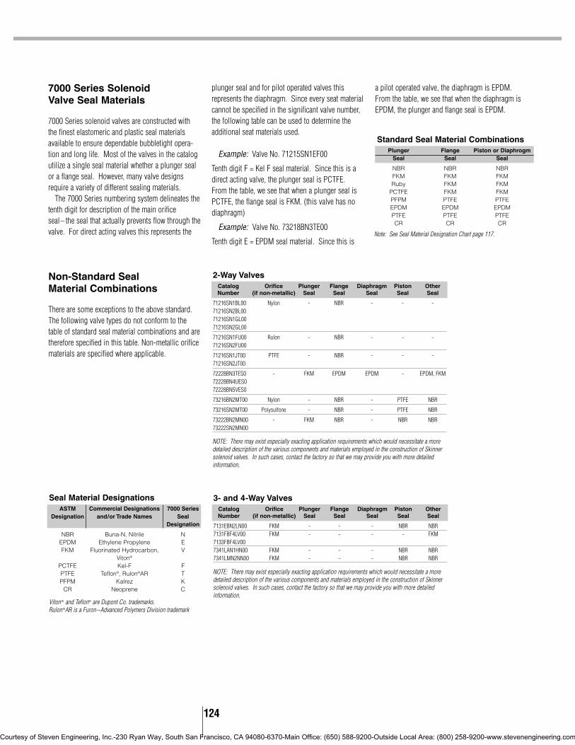
124
7000 Series Solenoid Valve Seal Materials
7000 Series solenoid valves are constructed withthe finest elastomeric and plastic seal materialsavailable to ensure dependable bubbletight opera-tion and long life. Most of the valves in the catalogutilize a single seal material whether a plunger sealor a flange seal. However, many valve designsrequire a variety of different sealing materials.
The 7000 Series numbering system delineates thetenth digit for description of the main orificeseal– the seal that actually prevents flow through thevalve. For direct acting valves this represents the
plunger seal and for pilot operated valves thisrepresents the diaphragm. Since every seat materialcannot be specified in the significant valve number,the following table can be used to determine theadditional seat materials used.
Example: Valve No. 71215SN1EF00
Tenth digit F = Kel F seal material. Since this is adirect acting valve, the plunger seal is PCTFE.From the table, we see that when a plunger seal isPCTFE, the flange seal is FKM. (this valve has nodiaphragm)
Example: Valve No. 73218BN3TE00
Tenth digit E = EPDM seal material. Since this is
a pilot operated valve, the diaphragm is EPDM.From the table, we see that when the diaphragm isEPDM, the plunger and flange seal is EPDM.
Seal Material DesignationsASTM Commercial Designations 7000 Series
Designation and/or Trade Names SealDesignation
NBR Buna-N, Nitrile NEPDM Ethylene Propylene EFKM Fluorinated Hydrocarbon, V
Viton®
PCTFE Kel-F FPTFE Teflon®, Rulon®AR TPFPM Kalrez K
CR Neoprene C
Viton ® and Teflon® are Dupont Co. trademarks.Rulon ®AR is a Furon–Advanced Polymers Division trademark
Non-Standard Seal Material Combinations
There are some exceptions to the above standard.The following valve types do not conform to thetable of standard seal material combinations and aretherefore specified in this table. Non-metallic orificematerials are specified where applicable.
NOTE: There may exist especially exacting application requirements which would necessitate a moredetailed description of the various components and materials employed in the construction of Skinnersolenoid valves. In such cases, contact the factory so that we may provide you with more detailedinformation.
NOTE: There may exist especially exacting application requirements which would necessitate a moredetailed description of the various components and materials employed in the construction of Skinnersolenoid valves. In such cases, contact the factory so that we may provide you with more detailedinformation.
2-Way ValvesCatalog Orifice Plunger Flange Diaphragm Piston OtherNumber (if non-metallic) Seal Seal Seal Seal Seal
71216SN1BL00 Nylon - NBR - - -71216SN2BL0071216SN1GL0071216SN2GL00
71216SN1FU00 Rulon - NBR - - -71216SN2FU00
71216SN1JT00 PTFE - NBR - - -71216SN2JT00
72228BN3TES0 - FKM EPDM EPDM - EPDM, FKM72228BN4UES072228BN5VES0
73216BN2MT00 Nylon - NBR - PTFE NBR
73216SN2MT00 Polysulfone - NBR - PTFE NBR
73222BN2MN00 - FKM NBR - NBR NBR73222SN2MN00
3- and 4-Way ValvesCatalog Orifice Plunger Flange Diaphragm Piston OtherNumber (if non-metallic) Seal Seal Seal Seal Seal
7131EBN2LN00 FKM - - - NBR NBR7131FBF4LV00 FKM - - - - FKM7133FBF4LV007341LAN1HN00 FKM - - - NBR NBR7341LMN2NN00 FKM - - - NBR NBR
Standard Seal Material CombinationsPlunger Flange Piston or Diaphrogm
Seal Seal Seal
NBR NBR NBRFKM FKM FKMRuby FKM FKM
PCTFE FKM FKMPFPM PTFE PTFEEPDM EPDM EPDMPTFE PTFE PTFECR CR CR
Note: See Seal Material Designation Chart page 117.
Courtesy of Steven Engineering, Inc.-230 Ryan Way, South San Francisco, CA 94080-6370-Main Office: (650) 588-9200-Outside Local Area: (800) 258-9200-www.stevenengineering.com

125
S100, S200, S300-Screw Terminations
DRAW
INGS
D100, D200, D300-DIN Terminations (DIN 43650A and ISO 4400)
L111, L222-Leaded Terminations
T100-Tab Terminations
Integrated Coils and Terminal Box Dimensions
The valve construction reference drawings provide outline dimensions for allpressure vessels contained in this catalog. They are shown with the 1/2”conduit style integrated coil as standard. The individual coil drawings on thispage provide dimensions for the other 7000 Series integrated coils. To applythese coil dimensions to any of the standard valve construction references, adatum line (cL) has been included which corresponds to the conduit hubcenterline dimension of the 1/2” conduit style integrated coil.
* Option DB: Slotted Head (#8-32 TH’D)Option TB: 9/64 Socket Head(M3X0.05TH’D)
Option DB, TB-Terminal Box
All dimensions in inches.
.71_›
.71
_
›
Courtesy of Steven Engineering, Inc.-230 Ryan Way, South San Francisco, CA 94080-6370-Main Office: (650) 588-9200-Outside Local Area: (800) 258-9200-www.stevenengineering.com

126
3000 Series Numbering System DesignatorsPressure 1 Series Designation 3 3000 Series
Vessel 2 Operations 1 Direct Acting, 6 Watt9 Direct Acting, 3 Watt
3 Ways 2 Two-Way(Functional Type) 3 Three-Way
4 Flow Pattern 1 Normally Closed3 Multipurpose8 Directional9 Normally Open, Ported Sleeve
5 Family B B
6 Body Material B BrassJ Operator (No Body)S 303 Stainless Steel
7 Process Connection A Male Straight ThreadN Female National Pipe Thread
8 Pipe Size 1 1/8”6 5/16-24 UNF7 3/4-32 UNF
9 Orifice A 1/32”E 3/64”G 1/16”J 5/64”L 3/32”N 1/8”Q 5/32”
10 Seal Material E EPDMN NBRV FKM
11 Mechanical Option 00 None12 AD 1/8” NPT Sleeve Adapter
C# Aluminum, Female 1/8” NPT, 2, 3, or 4 Station Cavity Manifold BlockHT Helium Leak TestedN0 Cleaned for Oxygen Service
Housing 13 Housing BB 1/2” Conduit14 N0 No Housing (Integrated Coil)
RR GrommetYY Yoke
Coil 15 Coil Designation M1S1 Integrated Molded, 1/4” Tab, 6W*, Class BMC11 Integrated Class F, 1/2” Conduit 18” Leads, 6W, NEMA 4XMH11 Integrated Class F, 1/2” Conduit 18” Leads, 6W, NEMA 4X, 7, 9
16 M3J5 Integrated Molded, 12” Leads, 6W, Class B17 M4S1 Integrated Molded, 1/4” Tab, 3W, Class B18 M6J5 Integrated Molded, 12” Leads, 3W, Class B
T1J1 Taped 12” Leads, 6W, Class BT3J1 Taped 12” Leads, 3W, Class B
19 Voltage Code P0 24/50-60 Hz AC20 P3 110/50 Hz, 120/60 Hz AC
Q3 220/50 Hz, 240/60 Hz ACC1 12 VDCC2 24 VDC
* For all 6 watt Coils, actual wattage for 24/60 Volts is 7.5.
3000 SERIES TECHNICAL INFORMATION
Courtesy of Steven Engineering, Inc.-230 Ryan Way, South San Francisco, CA 94080-6370-Main Office: (650) 588-9200-Outside Local Area: (800) 258-9200-www.stevenengineering.com

127
Electrical Enclosure Options
A coil enclosure is needed to complete the magneticflux path of conventional molded coils and specialtycoils. The enclosure can also serve to protect thecoil and provide a means to accommodate theelectrical connection. This section describes themost common electrical enclosure optionsavailable.
3000 Series Enclosure Options3000 Series integrated coils are a one-pieceassembly which requires only a nut and washer(enclosure code N0) to fasten to the pressurevessel. The 3000 Series conventional enclosureselection complements the integrated coil offeringproviding flexibility in product type and installation.
3000 Series Repair Kits/Accessories
Repair kits are available for all Skinner 3000 Seriesvalves. These kits include a new plunger assemblyand plunger return spring. Specify the kit you needby the part number listed, which corresponds to thetype of valve and seal material to be rebuilt.
Coils
To determine the approximate Holding or InrushCurrent for AC voltages including 24/60, 120/60,240/60 and 480/60 volts in amperes, divide thevoltage into the VA rating indicated in the AC Power
Consumption tables. DC valves have no inrushcurrent. The current rating in amperes for DCvalves are shown in the DC Table. Figures arebased on nominal values and will vary slightlydepending on operating voltage and coil tolerances.
Coil Picture Enclosure Description ApplicableCode CoilsRR Grommet Enclosure T1J1, T3J1
BB 1/2” Conduit Connection T1J1, T3J1
YY Yoke. For use where open enclosure is suitable T1J1, T3J1
N0 Nut for Integrated Molded coils M1S1, M4S1M3J5, M6J5
N0 Nut and Washer for 1/2” Conduit NEMA coils MC11, HC11
A, B, C, MB and V9 SeriesCurrent (Amperes) DC Current Consumption Ratings
AC Power Consumption RatingsVA VA Coil Type
Valve Series Holding Inrush Valve Series 6 Volt 12 Volt 24 Volt 120 Volt
Two-way B 17 9.7 Two-way B 1.05 0.53 0.26 0.05Three-way B 19 12 Three-way B 1.05 0.53 0.26 0.05Two-way C 25 16 Two-way C 1.17 0.58 0.29 0.06Three-way C 25 16 Three-way C 1.17 0.58 0.29 0.06Two-way A 122 49 Two-way A - - - -Three-way A 82 40 Three-way A 2.33 1.17 0.58 0.12Three-way MB 12 6.5 Three-way MB 0.83 0.42 0.21 0.04Four-way MB 12 6.5 Four-way MB 0.83 0.42 0.21 0.04Four-way V9* 32.5 17.5 Four-way V9* 1.42 0.71 0.35 0.07
* Per coil * Per coil
A, B, C, MB AND V9 SERIES INFORMATION
Flow Pattern NBR EPDM FKM
2-Way Normally Closed 3K3121N 3K3121E 3K3121V2-Way Normally Open 3K3129N 3K3129E 3K3129V3-Way Normally Closed 3K3131N 3K3131E 3K3131V3-Way Normally Open 3K3139N 3K3139E 3K3139V3-Way Multipurpose 3K3133N 3K3133E 3K3133V3-Way Directional Control 3K3138N 3K3138E 3K3138V
Universal Mounting Bracket–B19-006 SS Adaptor with Gasket = 300-22-004
Courtesy of Steven Engineering, Inc.-230 Ryan Way, South San Francisco, CA 94080-6370-Main Office: (650) 588-9200-Outside Local Area: (800) 258-9200-www.stevenengineering.com

DELIVERY INFORMATION
Parker Fluid Control Division establishes a classifi cation for every item made that identifi es how long it should take to build that item. This designation is called “Product Class”. Those items that are the most common are being referred to as “STANDARD PRODUCTS”.
We have a unique structure in the industry which allows for modular construction of our products.Toenhance our service to our customers we have focused our Product Class One offering on pressure vessels and integrated coil kits. The ability to “mix and match” pressure vessels and coil kits allows distribution to offer a variety of product combinations unsurpassed in market place.
STANDARD PRODUCTS(Product Class 1)
NON STANDARD PRODUCTSThese products are made to order. Lead times are typically tothe chart to the right, listed by product class. An electronic price fi le is available to you which identifi es each item’s “product class” and “lead time”. This fi le is available on PHconnect.com for download.
The items marked “CF” in the price book refer to consult factory. Some of the items may have been obsoleted and our customer service and technical sales departments can help you with cross overs to more current valves. Contact your customer service representative for assistance.
This modular design, will give you
fl exibility with stocking our products.
Choose from the list of Product Class Ones
located after the table of contents to begin
stocking readily available products,
50 or less ships in 24 hours!* Assembled combinations of Product Class One items
ship in 5 working days.
*Skinner products shown
PRODUCT CLASS
1: Ships within 24 hours**50 pieces or less ship within 24 hours**Quantities greater than 50 pieces will ship within 5 working days
2: Ships within 5 working days
3: Ships within 15 working days
4: Ships within 20 working days
6: Ships within 30 working days
7: Ships within 60 working days
N: Date to be Assigned
CF: Consult Factory
Courtesy of Steven Engineering, Inc.-230 Ryan Way, South San Francisco, CA 94080-6370-Main Office: (650) 588-9200-Outside Local Area: (800) 258-9200-www.stevenengineering.com

Offer Of Sale
The items described in this document are hereby offered for sale at prices to be established by Parker Hannifi n Corporation, its subsidiaries and its authorized distributors. This offer and its acceptance by any customer (“Buyer”) shall be governed by all of the following Terms and Conditions. Buyer’s order for any item described in its document, when communicated to Parker Hannifi n Corporation, its subsidiary or an authorized distributor (“Seller’] verbally or in writing, shall constitute acceptance of this offer.
1. Terms and Conditions of Sale: All descriptions, quotations, proposals, offers, acknowledgments, acceptances and sales of Seller’s products are subject to and shall be governed exclusively by the terms and conditions stated herein. Buyer’s acceptance of any offer to sell is limited to these terms and conditions. Any terms or conditions in addition to, or inconsistent with those stated herein, proposed by Buyer in any acceptance of an offer by Seller, are hereby objected to No such additional, different or inconsistent terms and conditions shall be-come part of the contract between Buyer and Seller unless expressly ac¬cepted in writing by Seller. Seller’s acceptance of any offer to purchase by Buyer is expressly conditional upon Buyer’s assent to all the terms and conditions stated herein, including any terms in addition to, or inconsistent with those contained in Buyer’s offer. Acceptance of Seller’s products shall in all events constitute such assent.
2. Payment: Payment shall be made by Buyer net 30 days from the date of delivery of the items purchased hereunder. Any claims by Buyer for omissions or shortages in a shipment shall be waived unless Seller receives notice thereof within 30 days after Buyer’s receipt of the shipment. The minimum order amount is $125.00 net, unless otherwise noted on the quotation .
3. Delivery: Unless otherwise provided on the face hereof, delivery shall be made F.O.B. Seller’s plant. Regardless of the method of delivery, however, risk of loss shall pass to Buyer upon Seller’s delivery to a carrier. Any delivery dates shown are approximate only and Seller shall have no liability for any de-lays in delivery. Shipments are made by common carrier. Any premium freight must be requested and paid for by the Buyer.
4. Warranty: Seller warrants that the items sold hereunder shall be free from defects in material or workmanship for a period of 2 years from the date of shipment to Buyer, or 2,000 hours of use, whichever expires fi rst. Exception to this is the Angle Body Valve line has a 1 year warranty. THIS WARRANTY COMPRISES THE SOLE AND ENTIRE WARRANTY PERTAINING TO ITEMS PROVIDED HEREUNDER. SELLER MAKES NO OTHER WAR-RANTY, GUARANTEE, OR REPRESENTA TION OF ANY KIND WHAT-SOEVER. ALL OTHER WARRANTIES, INCLUDING BUT NOT LIMITED TO, MERCHANTIBILITY AND FITNESS FOR PURPOSE, WHETHER EXPRESS, IMPLIED, OR ARIS. ING BY OPERATION OF LAW, TRADE USAGE, OR COURSE OF DEAL ING ARE HEREBY DISCLAIMED. NOTWITHSTANDING THE FOREGOING, THERE ARE NO WARRAN-TIES WHATSOEVER ON ITEMS BUILT OR ACQUIRED WHOLLY OR PARTIALLY, TO BUYER’S DESIGNS OR SPECIFICATIONS.
5. Limitation Of Remedy: SELLER’S LIABILITY ARISING FROM OR IN ANY WAY CONNECTED WITH THE ITEMS SOLD OR THIS CONTRACT SHALL BE LIMITED EXCLUSIVELY TO REPAIR OR REPLACEMENT OF THE ITEMS SOLD OR REFUND OF THE PURCHASE PRICE PAID BY BUYER, AT SELLER’S SOLE OPTION. IN NO EVENT SHALL SELLER BE LIABLE FOR ANY INCIDENTAL, CONSEQUENTIAL OR SPECIAL DAMAGES OF ANY KIND OR NATURE WHATSOEVER, INCLUDING BUT NOT LIMITED TO LOST PROFITS ARISING FROM OR IN ANY WAY CONNECTED WITH THIS AGREEMENT OR ITEMS SOLD HERE-UNDER, WHETHER ALLEGED TO ARISE FROM BREACH OF CON-TRACT, EXPRESS OR IMPLIED WARRANTY, OR IN TORT, INCLUD-ING WITHOUT LIMITATION, NEGLIGENCE, FAILURE TO WARN OR STRICT LIABILITY.
6. Changes, Reschedules and Cancellations: Buyer may request to modify the designs or specifi cations for the items sold hereunder as well as the quantities and delivery dates thereof, or may request to cancel all or part of this order, however, no such requested modifi cation or cancellation shall become part of the contract between Buyer and Seller unless accepted by Seller in a written amendment to this Agreement. Acceptance of any such requested modifi cation or cancellation shall be at Seller’s discretion, and shall be upon such terms and conditions as Seller may require.
7. Special Tooling: A tooling charge may be imposed for any special tooling, including without limitation, dies, fi xtures, molds and patterns, acquired to manufacture items sold pursuant to this contract. Such special tooling shall be and remain Seller’s property notwithstanding payment of any charges by
Buyer. In no event will Buyer acquire any interest in apparatus belonging to Seller which is utilized in the manufacture of the items sold hereunder, even if such apparatus has been specially converted or adapted for such manufacture and notwithstanding any charges paid by Buyer. Unless otherwise agreed, Seller shall have the right to alter, discard or otherwise dispose of any special tooling or other property in its sole discretion at any time.
8. Buyer’s Property: Any designs, tools, patterns, materials, drawings, confi -dential information or equipment furnished by Buyer or any other items which become Buyer’s property, may be considered obsolete and may be destroyed by Seller after two (2) consecutive years have elapsed without Buyer placing an order for the items which are manufactured using such property. Seller shall not be responsible for any loss or damage to such property while it is in Seller’s possession or control.
9. Taxes: Unless otherwise indicated on the face hereof, all prices and charges are exclusive of excise, sales, use, property, occupational or like taxes which may be imposed by any taxing authority upon the manufacture, sale or delivery of the items sold hereunder. If any such taxes must be paid by Seller or if Seller is liable for the collection of such tax, the amount thereof shall be in addition to the amounts for the items sold. Buyer agrees to pay all such taxes or to re-imburse Seller therefore upon receipt of its invoice. If Buyer claims exemption from any sales, use or other tax imposed by any taxing authority, Buyer shall save Seller harmless from and against any such tax, together with any interest or penalties thereon which may be assessed if the items are held to be taxable.
10. Indemnity For Infringement of Intellectual Property Rights: Seller shall have no liability for infringement of any patents, trademarks, copyrights, trade dress, trade secrets or similar rights except as provided in this Part 10. Seller will defend and indemnify Buyer against allegations of infringement of U.S. patents, U.S. trademarks, copyrights, trade dress and trade secrets (hereinafter ‘Intellectual Property Rights’). Seller will defend at its expense and will pay the cost of any settlement or damages awarded in an action brought against Buyer based on an allegation that an item sold pursuant to this contract infringes the Intellectual Property Rights of a third party. Seller’s obligation to defend and indemnify Buyer is contingent on Buyer notifying Seller within ten (10) days after Buyer becomes aware of such allegations of infringement, and Seller having sole control over the defense of any allegations or actions includ-ing all negotiations for settlement or compromise. If an item sold hereunder is subject to a claim that it infringes the Intellectual Property Rights of a third party, Seller may, at its sole expense and option, procure for Buyer the right to continue using said item, replace or modify said item so as to make it nonin-fringing, or offer to accept return of said item and return the purchase price less a reasonable allowance for depreciation. Notwithstanding the foregoing, Seller shall have no liability for claims of infringement based on information pro-vided by Buyer, or directed to items delivered hereunder for which the designs are specifi ed in whole or part by Buyer, or infringements resulting from the modifi cation, combination or use in a system of any item sold hereunder. The foregoing provisions of this Part 10 shall constitute Seller’s sole and exclusive liability and Buyer’s sole and exclusive remedy for infringement of Intellectual Property Rights.
If a claim is based on information provided by Buyer or if the design for an item delivered hereunder is specifi ed in whole or in part by Buyer, Buyer shall defend and indemnify Seller for all costs, expenses or judgments resulting from any claim that such item infringes any patent, trademark, copyright, trade dress, trade secret or any similar right.
11. Force Majeure: Seller does not assume the risk of and shall not be liable for delay or failure to perform any of Seller’s obligations by reason of circum-stances beyond the reasonable control of Seller (hereinafter ‘events of Force Majeure]. Events of Force Majeure shall include without limitation, accidents, acts of God, strikes or labor disputes, acts, laws, rules or regulations of any government or government agency, fi res, fl oods, delays or failures in delivery of carriers or suppliers, shortages of materials and any other cause beyond Seller’s control.
12. Entire Agreement/Governing Law: The terms and conditions set forth herein, together with any amendments, modifi cations and any different terms or conditions expressly accepted by Seller in writing, shall constitute the entire Agreement concerning the items sold, and there are no oral or other representa-tions or agreements which pertain thereto. This Agreement shall be governed in all respects by the law of the State of Ohio. No actions arising out of the sale of the items sold hereunder or this Agreement may be brought by either party more than two (2) years after the cause of action accrues.
PD4099 9/88 (Rev B)
Courtesy of Steven Engineering, Inc.-230 Ryan Way, South San Francisco, CA 94080-6370-Main Office: (650) 588-9200-Outside Local Area: (800) 258-9200-www.stevenengineering.com

Courtesy of Steven Engineering, Inc.-230 Ryan Way, South San Francisco, CA 94080-6370-Main Office: (650) 588-9200-Outside Local Area: (800) 258-9200-www.stevenengineering.com

Courtesy of Steven Engineering, Inc.-230 Ryan Way, South San Francisco, CA 94080-6370-Main Office: (650) 588-9200-Outside Local Area: (800) 258-9200-www.stevenengineering.com

1
Gold Ring Product Line
A wide range of two-way, three-way, andfour-way Gold Ring solenoid valves in brassor stainless steel, along with a wide varietyof seal and disc materials, ensures that wehave a standard valve to fit most applications.Special purpose solenoid valves forcryogenic or vacuum service applicationsare also available.
If a unique application requires a uniqueproduct, our technical and manufacturingexperience allows us to develop and supplythe right valve for that application.
Unit valves and unit solenoids enable usto offer versatility in stocking and manufac-turing requirements. With the introductionof Parker’s optional Gold Ring IITM completelyencapsulated solenoid, Type 4X require-ments can also be met with unit valves andunit solenoids. Of course, completelyassembled valves can be supplied at noextra cost. In either case, applicable agencyapprovals prevail.
Courtesy of Steven Engineering, Inc.-230 Ryan Way, South San Francisco, CA 94080-6370-Main Office: (650) 588-9200-Outside Local Area: (800) 258-9200-www.stevenengineering.com
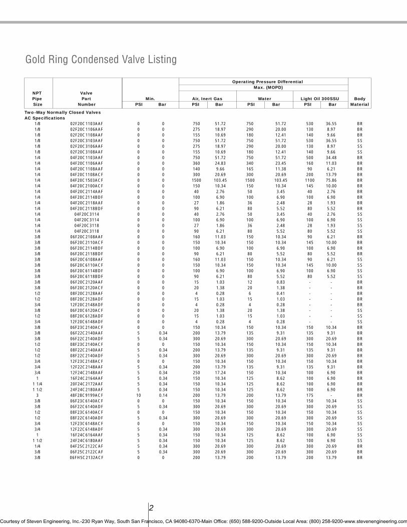
Operating Pressure DifferentialMax. (MOPD)
NPT ValvePipe Part Min. Air, Inert Gas Water Light Oil 300SSU BodySize Number PSI Bar PSI Bar PSI Bar PSI Bar Material
Two-Way Normally Closed ValvesAC Specifications
1/8 02F20C1103AAF 0 0 750 51.72 750 51.72 530 36.55 BR1/8 02F20C1106AAF 0 0 275 18.97 290 20.00 130 8.97 BR1/8 02F20C1108AAF 0 0 155 10.69 180 12.41 140 9.66 BR1/8 02F20C3103AAF 0 0 750 51.72 750 51.72 530 36.55 SS1/8 02F20C3106AAF 0 0 275 18.97 290 20.00 130 8.97 SS1/8 02F20C3108AAF 0 0 155 10.69 180 12.41 140 9.66 SS1/4 04F20C1103AAF 0 0 750 51.72 750 51.72 500 34.48 BR1/4 04F20C1106AAF 0 0 360 24.83 340 23.45 160 11.03 BR1/4 04F20C1108AAF 0 0 140 9.66 165 11.38 90 6.21 BR1/4 04F20C1108ACF 0 0 300 20.69 300 20.69 200 13.79 BR1/4 04F20C1503ACF 0 0 1500 103.45 1500 103.45 1100 75.86 BR1/4 04F20C2100ACF 0 0 150 10.34 150 10.34 145 10.00 BR1/4 04F20C2114AAF 0 0 40 2.76 50 3.45 40 2.76 BR1/4 04F20C2114BDF 0 0 100 6.90 100 6.90 100 6.90 BR1/4 04F20C2118AAF 0 0 27 1.86 36 2.48 28 1.93 BR1/4 04F20C2118BDF 0 0 90 6.21 80 5.52 80 5.52 BR1/4 04F20C3114 0 0 40 2.76 50 3.45 40 2.76 SS1/4 04F20C3114 0 0 100 6.90 100 6.90 100 6.90 SS1/4 04F20C3118 0 0 27 1.86 36 2.48 28 1.93 SS1/4 04F20C3118 0 0 90 6.21 80 5.52 80 5.52 SS3/8 06F20C2108AAF 0 0 160 11.03 150 10.34 90 6.21 BR3/8 06F20C2110ACF 0 0 150 10.34 150 10.34 145 10.00 BR3/8 06F20C2114BDF 0 0 100 6.90 100 6.90 100 6.90 BR3/8 06F20C2118BDF 0 0 90 6.21 80 5.52 80 5.52 BR3/8 06F20C6108AAF 0 0 160 11.03 150 10.34 90 6.21 SS3/8 06F20C6110ACF 0 0 150 10.34 150 10.34 145 10.00 SS3/8 06F20C6114BDF 0 0 100 6.90 100 6.90 100 6.90 SS3/8 06F20C6118BDF 0 0 90 6.21 80 5.52 80 5.52 SS3/8 06F20C2120AAF 0 0 15 1.03 12 0.83 - - BR3/8 06F20C2120ACF 0 0 20 1.38 20 1.38 - - BR1/2 08F20C2128AAF 0 0 4 0.28 6 0.41 - - BR1/2 08F20C2128ADF 0 0 15 1.03 15 1.03 - - BR3/4 12F20C2148ADF 0 0 4 0.28 4 0.28 - - BR3/8 06F20C6120ACF 0 0 20 1.38 20 1.38 - - SS1/2 08F20C6128ADF 0 0 15 1.03 15 1.03 - - SS3/4 12F20C6148ADF 0 0 4 0.28 4 0.28 - - SS3/8 06F23C2140ACF 0 0 150 10.34 150 10.34 150 10.34 BR3/8 06F22C2140AAF 5 0.34 200 13.79 135 9.31 135 9.31 BR3/8 06F22C2140ADF 5 0.34 300 20.69 300 20.69 300 20.69 BR1/2 08F23C2140ACF 0 0 150 10.34 150 10.34 150 10.34 BR1/2 08F22C2140AAF 5 0.34 200 13.79 135 9.31 135 9.31 BR1/2 08F22C2140ADF 5 0.34 300 20.69 300 20.69 300 20.69 BR3/4 12F23C2148ACF 0 0 150 10.34 150 10.34 150 10.34 BR3/4 12F22C2148AAF 5 0.34 200 13.79 135 9.31 135 9.31 BR3/4 12F24C2148AAF 5 0.34 250 17.24 150 10.34 100 6.90 BR1 16F24C2164AAF 5 0.34 150 10.34 125 8.62 100 6.90 BR
1 1/4 20F24C2172AAF 5 0.34 150 10.34 125 8.62 100 6.90 BR1 1/2 24F24C2180AAF 5 0.34 150 10.34 125 8.62 100 6.90 BR
3 48F28C9199ACF 10 0.14 200 13.79 200 13.79 175 - BR3/8 06F23C6140ACF 0 0 150 10.34 150 10.34 150 10.34 SS3/8 06F22C6140ADF 5 0.34 300 20.69 300 20.69 300 20.69 SS1/2 08F23C6140ACF 0 0 150 10.34 150 10.34 150 10.34 SS1/2 08F22C6140ADF 5 0.34 300 20.69 300 20.69 300 20.69 SS3/4 12F23C6148ACF 0 0 150 10.34 150 10.34 150 10.34 SS3/4 12F22C6148ADF 5 0.34 300 20.69 300 20.69 300 20.69 SS1 16F24C6164AAF 5 0.34 150 10.34 125 8.62 100 6.90 SS
1 1/2 24F24C6180AAF 5 0.34 150 10.34 125 8.62 100 6.90 SS1/4 04F25C2122CAF 5 0.34 300 20.69 300 20.69 300 20.69 BR3/8 06F25C2122CAF 5 0.34 300 20.69 300 20.69 300 20.69 BR3/8 06FH5C2132ACF 0 0 200 13.79 200 13.79 200 13.79 BR
2
Gold Ring Condensed Valve Listing
Courtesy of Steven Engineering, Inc.-230 Ryan Way, South San Francisco, CA 94080-6370-Main Office: (650) 588-9200-Outside Local Area: (800) 258-9200-www.stevenengineering.com
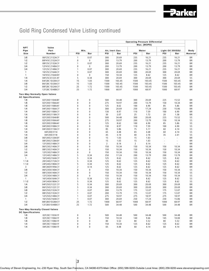
3
Operating Pressure DifferentialMax. (MOPD)
NPT ValvePipe Part Min. Air, Inert Gas Water Light Oil 300SSU BodySize Number PSI Bar PSI Bar PSI Bar PSI Bar Material
3/8 06F25C2132ACF 1 0.07 300 20.69 235 16.21 235 16.21 BR1/2 08FH5C2132ACF 0 0 200 13.79 200 13.79 200 13.79 BR1/2 08F25C2132ACF 1 0.07 300 20.69 235 16.21 235 16.21 BR3/4 12FH5C2148ACF 0 0 200 13.79 200 13.79 200 13.79 BR3/4 12F25C2148ACF 1 0.07 300 20.69 235 16.21 235 16.21 BR1 16F25C2164ACF 1 0.07 300 20.69 300 20.69 300 20.69 BR1 16FH5C2164ADF 0 0 150 10.34 125 8.62 125 8.62 BR
1/4 04F25C6122CAF 5 0.34 300 20.69 300 20.69 300 20.69 SS1/4 04F28C1D20ACF 15 1.03 1500 103.45 1500 103.45 1500 103.45 BR3/8 06F28C1D20ACF 15 1.03 1500 103.45 1500 103.45 1500 103.45 BR1/2 08F28C1D24ACF 25 1.72 1500 103.45 1500 103.45 1500 103.45 BR3/4 12F28C1D48BCF 25 1.72 1000 68.97 1000 68.97 1000 68.97 BR
Two-Way Normally Open ValvesAC Specifications
1/8 02F20O1104ABF 0 0 500 34.48 300 20.69 225 15.52 BR1/8 02F20O1106AAF 0 0 275 18.97 200 13.79 150 10.34 BR1/8 02F20O1108AAF 0 0 125 8.62 100 6.90 85 5.86 BR1/4 04F20O1106ACF 0 0 300 20.69 250 17.24 230 15.86 BR1/4 04F20O1108ACF 0 0 130 8.97 110 7.59 100 6.90 BR1/4 04F20O2118ACF 0 0 30 2.07 25 1.72 20 1.38 BR1/8 02F20O3104ABF 0 0 500 34.48 300 20.69 225 15.52 SS1/8 02F20O3106AAF 0 0 275 18.97 200 13.79 150 10.34 SS1/8 02F20O3108AAF 0 0 125 8.62 100 6.90 85 5.86 SS1/4 04F20O3108ACF 0 0 130 8.97 110 7.59 100 6.90 SS1/4 04F20O3110ACF 0 0 85 5.86 75 5.17 60 4.14 SS1/4 04F20O3114 0 0 65 4.48 65 4.48 60 4.14 SS1/4 04F20O3118 0 0 45 3.10 40 2.76 35 2.41 SS3/8 06F20O2120ADF 0 0 15 1.03 15 1.03 - - BR1/2 08F20O2128ADF 0 0 15 1.03 15 1.03 - - BR3/4 12F20O2148ACF 0 0 2 0.14 2 0.14 - - BR3/8 06F23O2140ACF 0 0 150 10.34 150 10.34 150 10.34 BR1/2 08F23O2140ACF 0 0 150 10.34 150 10.34 150 10.34 BR3/4 12F23O2148ACF 0 0 150 10.34 150 10.34 150 10.34 BR3/4 12F24O2148ACF 5 0.34 250 17.24 200 13.79 200 13.79 BR1 16F24O2164ACF 5 0.34 125 8.62 125 8.62 125 8.62 BR
1 1/4 20F24O2172ACF 5 0.34 125 8.62 125 8.62 125 8.62 BR1 1/2 24F24O2180ACF 5 0.34 125 8.62 125 8.62 125 8.62 BR
3 48F28O9199ACF 2 0.14 125 8.62 125 8.62 125 8.62 BR3/8 06F23O6140ACF 0 0 150 10.34 150 10.34 150 10.34 SS1/2 08F23O6140ACF 0 0 150 10.34 150 10.34 150 10.34 SS3/4 12F23O6148ACF 0 0 150 10.34 150 10.34 150 10.34 SS1 16F24O6164ACF 5 0.34 125 8.62 125 8.62 125 8.62 SS
1 1/2 24F24O6180ACF 5 0.34 125 8.62 125 8.62 125 8.62 SS1/4 04F25O2122CCF 5 0.34 300 20.69 300 20.69 300 20.69 BR3/8 06F25O2122CCF 5 0.34 300 20.69 300 20.69 300 20.69 BR3/8 06F25O2132ACF 1 0.07 200 13.79 175 12.07 175 12.07 BR1/2 08F25O2132ACF 1 0.07 200 13.79 175 12.07 175 12.07 BR3/4 12F25O2148ACF 1 0.07 275 18.97 275 18.97 275 18.97 BR1 16F25O2164ACF 1 0.07 300 20.69 250 17.24 230 15.86 BR
1/2 08F28O1D28ACF 25 1.72 1000 68.97 1000 68.97 1000 68.97 BR3/4 12F28O1D48BCF 25 1.72 500 34.48 500 34.48 500 34.48 BR
Two-Way Normally Closed ValvesDC Specifications
1/8 02F20C1103A1F 0 0 500 34.48 500 34.48 500 34.48 BR1/8 02F20C1106A1F 0 0 150 10.34 140 9.66 145 10.00 BR1/8 02F20C1108A1F 0 0 80 5.52 80 5.52 80 5.52 BR1/4 04F20C1106A1F 0 0 150 10.34 125 8.62 125 8.62 BR1/4 04F20C1108A1F 0 0 65 4.48 60 4.14 60 4.14 BR
Gold Ring Condensed Valve Listing continued
Courtesy of Steven Engineering, Inc.-230 Ryan Way, South San Francisco, CA 94080-6370-Main Office: (650) 588-9200-Outside Local Area: (800) 258-9200-www.stevenengineering.com
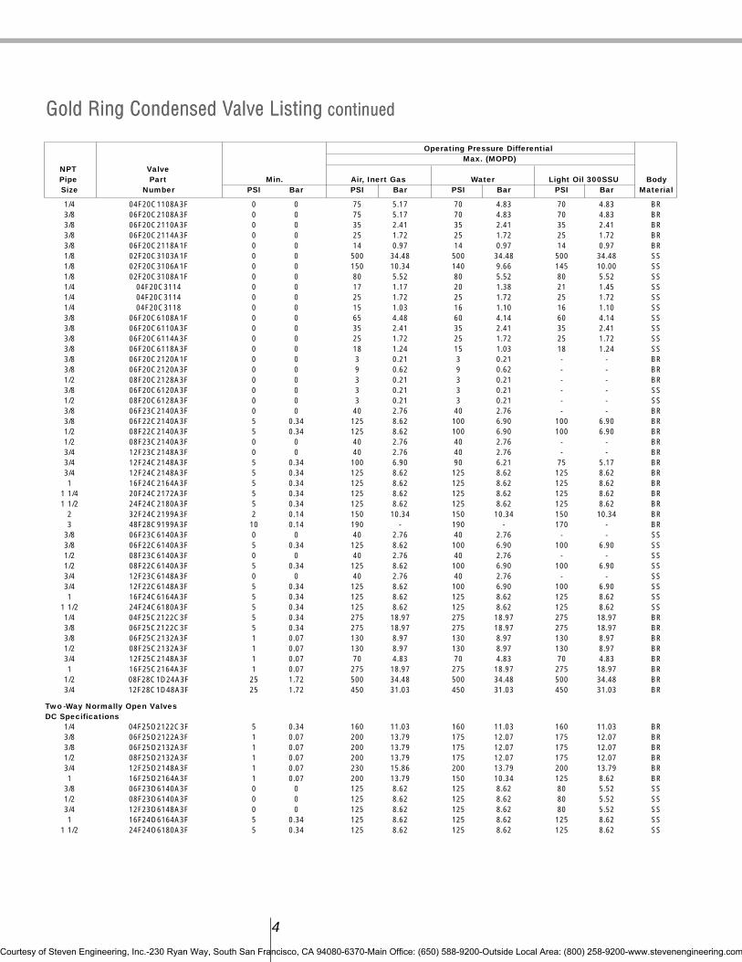
Operating Pressure DifferentialMax. (MOPD)
NPT ValvePipe Part Min. Air, Inert Gas Water Light Oil 300SSU BodySize Number PSI Bar PSI Bar PSI Bar PSI Bar Material
1/4 04F20C1108A3F 0 0 75 5.17 70 4.83 70 4.83 BR3/8 06F20C2108A3F 0 0 75 5.17 70 4.83 70 4.83 BR3/8 06F20C2110A3F 0 0 35 2.41 35 2.41 35 2.41 BR3/8 06F20C2114A3F 0 0 25 1.72 25 1.72 25 1.72 BR3/8 06F20C2118A1F 0 0 14 0.97 14 0.97 14 0.97 BR1/8 02F20C3103A1F 0 0 500 34.48 500 34.48 500 34.48 SS1/8 02F20C3106A1F 0 0 150 10.34 140 9.66 145 10.00 SS1/8 02F20C3108A1F 0 0 80 5.52 80 5.52 80 5.52 SS1/4 04F20C3114 0 0 17 1.17 20 1.38 21 1.45 SS1/4 04F20C3114 0 0 25 1.72 25 1.72 25 1.72 SS1/4 04F20C3118 0 0 15 1.03 16 1.10 16 1.10 SS3/8 06F20C6108A1F 0 0 65 4.48 60 4.14 60 4.14 SS3/8 06F20C6110A3F 0 0 35 2.41 35 2.41 35 2.41 SS3/8 06F20C6114A3F 0 0 25 1.72 25 1.72 25 1.72 SS3/8 06F20C6118A3F 0 0 18 1.24 15 1.03 18 1.24 SS3/8 06F20C2120A1F 0 0 3 0.21 3 0.21 - - BR3/8 06F20C2120A3F 0 0 9 0.62 9 0.62 - - BR1/2 08F20C2128A3F 0 0 3 0.21 3 0.21 - - BR3/8 06F20C6120A3F 0 0 3 0.21 3 0.21 - - SS1/2 08F20C6128A3F 0 0 3 0.21 3 0.21 - - SS3/8 06F23C2140A3F 0 0 40 2.76 40 2.76 - - BR3/8 06F22C2140A3F 5 0.34 125 8.62 100 6.90 100 6.90 BR1/2 08F22C2140A3F 5 0.34 125 8.62 100 6.90 100 6.90 BR1/2 08F23C2140A3F 0 0 40 2.76 40 2.76 - - BR3/4 12F23C2148A3F 0 0 40 2.76 40 2.76 - - BR3/4 12F24C2148A3F 5 0.34 100 6.90 90 6.21 75 5.17 BR3/4 12F24C2148A3F 5 0.34 125 8.62 125 8.62 125 8.62 BR1 16F24C2164A3F 5 0.34 125 8.62 125 8.62 125 8.62 BR
1 1/4 20F24C2172A3F 5 0.34 125 8.62 125 8.62 125 8.62 BR1 1/2 24F24C2180A3F 5 0.34 125 8.62 125 8.62 125 8.62 BR
2 32F24C2199A3F 2 0.14 150 10.34 150 10.34 150 10.34 BR3 48F28C9199A3F 10 0.14 190 - 190 - 170 - BR
3/8 06F23C6140A3F 0 0 40 2.76 40 2.76 - - SS3/8 06F22C6140A3F 5 0.34 125 8.62 100 6.90 100 6.90 SS1/2 08F23C6140A3F 0 0 40 2.76 40 2.76 - - SS1/2 08F22C6140A3F 5 0.34 125 8.62 100 6.90 100 6.90 SS3/4 12F23C6148A3F 0 0 40 2.76 40 2.76 - - SS3/4 12F22C6148A3F 5 0.34 125 8.62 100 6.90 100 6.90 SS1 16F24C6164A3F 5 0.34 125 8.62 125 8.62 125 8.62 SS
1 1/2 24F24C6180A3F 5 0.34 125 8.62 125 8.62 125 8.62 SS1/4 04F25C2122C3F 5 0.34 275 18.97 275 18.97 275 18.97 BR3/8 06F25C2122C3F 5 0.34 275 18.97 275 18.97 275 18.97 BR3/8 06F25C2132A3F 1 0.07 130 8.97 130 8.97 130 8.97 BR1/2 08F25C2132A3F 1 0.07 130 8.97 130 8.97 130 8.97 BR3/4 12F25C2148A3F 1 0.07 70 4.83 70 4.83 70 4.83 BR1 16F25C2164A3F 1 0.07 275 18.97 275 18.97 275 18.97 BR
1/2 08F28C1D24A3F 25 1.72 500 34.48 500 34.48 500 34.48 BR3/4 12F28C1D48A3F 25 1.72 450 31.03 450 31.03 450 31.03 BR
Two-Way Normally Open ValvesDC Specifications
1/4 04F25O2122C3F 5 0.34 160 11.03 160 11.03 160 11.03 BR3/8 06F25O2122A3F 1 0.07 200 13.79 175 12.07 175 12.07 BR3/8 06F25O2132A3F 1 0.07 200 13.79 175 12.07 175 12.07 BR1/2 08F25O2132A3F 1 0.07 200 13.79 175 12.07 175 12.07 BR3/4 12F25O2148A3F 1 0.07 230 15.86 200 13.79 200 13.79 BR1 16F25O2164A3F 1 0.07 200 13.79 150 10.34 125 8.62 BR
3/8 06F23O6140A3F 0 0 125 8.62 125 8.62 80 5.52 SS1/2 08F23O6140A3F 0 0 125 8.62 125 8.62 80 5.52 SS3/4 12F23O6148A3F 0 0 125 8.62 125 8.62 80 5.52 SS1 16F24O6164A3F 5 0.34 125 8.62 125 8.62 125 8.62 SS
1 1/2 24F24O6180A3F 5 0.34 125 8.62 125 8.62 125 8.62 SS
4
Gold Ring Condensed Valve Listing continuedGold Ring Condensed Valve Listing continued
Courtesy of Steven Engineering, Inc.-230 Ryan Way, South San Francisco, CA 94080-6370-Main Office: (650) 588-9200-Outside Local Area: (800) 258-9200-www.stevenengineering.com

5
Operating Pressure DifferentialMax. (MOPD)
NPT ValvePipe Part Min. Air, Inert Gas Water Light Oil 300SSU BodySize Number PSI Bar PSI Bar PSI Bar PSI Bar Material
1/2 08F23O2140A3F 0 0 125 8.62 125 8.62 80 5.52 BR3/4 12F23O2148A3F 0 0 125 8.62 125 8.62 80 5.52 BR3/4 12F24O2148A3F 5 0.34 125 8.62 125 8.62 125 8.62 BR1 16F24O2164A3F 5 0.34 125 8.62 125 8.62 125 8.62 BR
1 1/4 20F24O2172A3F 5 0.34 125 8.62 125 8.62 125 8.62 BR1 1/2 24F24O2180A3F 5 0.34 125 8.62 125 8.62 125 8.62 BR
2 32F24O2199A3F 2 0.14 125 8.62 125 8.62 125 8.62 BR3 48F28O9199A3F 2 0.14 125 8.62 125 8.62 125 8.62 BR
3/8 06F20O2120A3F 0 0 5 0.34 3 0.21 - - BR1/2 08F20O2128A3F 0 0 1 0.07 1 0.07 - - BR1/8 02F20O3104A1F 0 0 400 27.59 250 17.24 150 10.34 SS1/8 02F20O3106A1F 0 0 190 13.10 110 7.59 110 7.59 SS1/8 02F20O3108A1F 0 0 80 5.52 60 4.14 50 3.45 SS1/4 04F20O3108A3F 0 0 80 5.52 60 4.14 60 4.14 SS1/4 04F20O3110 0 0 45 3.10 30 2.07 30 2.07 SS1/8 02F20O1104A1F 0 0 400 27.59 250 17.24 150 10.34 BR1/8 02F20O1106A1F 0 0 190 13.10 110 7.59 110 7.59 BR1/8 02F20O1108A1F 0 0 80 5.52 60 4.14 50 3.45 BR1/4 04F20O1103A3F 0 0 500 34.48 500 34.48 500 34.48 BR1/4 04F20O2110A3F 0 0 45 3.10 30 2.07 30 2.07 BR
Hot Water and Steam Valves
Operating Pressure DifferentialMax. (MOPD)
NPT ValvePipe Part Min. Steam Hot Water BodySize Number PSI Bar PSI Bar PSI Bar Material
Two-Way Normally Closed ValvesAC Specifications
1/4 04FS0C3410ACH 0 0 110 7.59 - - BR3/8 06FS5C2332ACF 1 0.07 50 3.45 - - BR3/8 06FS5C2432ACF 1 0.07 80 5.52 - - BR3/8 06FS5C2432ACH 1 0.07 125 8.62 - - BR3/8 06FS3C2340ACF 0 0 50 3.45 150 10.34 BR1/2 08FS5C2332ACF 1 0.07 50 3.45 - - BR1/2 08FS5C2432ACF 1 0.07 80 5.52 - - BR1/2 08FS5C2432ACH 1 0.07 125 8.62 - - BR1/2 08FS3C2340ACF 0 0 50 3.45 150 10.34 BR3/4 12FS5C2348ACF 1 0.07 50 3.45 - - BR3/4 12FS5C2448ACF 1 0.07 80 5.52 - - BR3/4 12FS5C2448ACH 1 0.07 125 8.62 - - BR3/4 12FS3C2348ACF 0 0 50 3.45 150 10.34 BR1 16FS5C2364ACF 1 0.07 50 3.45 150 10.34 BR1 16FS5C2464ACF 1 0.07 80 5.52 - - BR1 16FS5C2464ACH 1 0.07 125 8.62 - - BR
1 1/4 20FS4C2372AAF 5 0.34 50 3.45 150 10.34 BR1 1/2 24FS4C2380AAF 5 0.34 50 3.45 150 10.34 BR
DC Specifications3/8 06F22C2340A3F 5 0.34 - - 100 6.90 BR3/8 06F23C2340A3F 0 0 - - 40 2.76 BR1/2 08F22C2340A3F 5 0.34 - - 100 6.90 BR1/2 08F23C2340A3F 0 0 - - 40 2.76 BR3/4 12F22C2348A3F 5 0.34 - - 100 6.90 BR3/4 12F23C2348A3F 0 0 - - 40 2.76 BR
Two-Way Normally OpenAC Specifications
3/8 06FS5O2432ACH 1 0.07 125 8.62 - - BR1/2 08FS5O2432ACH 1 0.07 125 8.62 - - BR3/4 12FS5O2448ACH 1 0.07 125 8.62 - - BR1 16FS5O2464ACH 1 0.07 125 8.62 - - BR
1 1/2 24FS4O2380ACF 5 0.34 50 3.45 - - BR
Gold Ring Condensed Valve Listing continuedGold Ring Condensed Valve Listing continued
Courtesy of Steven Engineering, Inc.-230 Ryan Way, South San Francisco, CA 94080-6370-Main Office: (650) 588-9200-Outside Local Area: (800) 258-9200-www.stevenengineering.com

Operating Pressure DifferentialMax. (MOPD)
NPT ValvePipe Part Min. Air, Inert Gas Water Light Oil 300SSU BodySize Number PSI Bar PSI Bar PSI Bar PSI Bar Material
Three-Way Normally Closed ValvesAC Specifications
1/8 02F30C1103AAF 0 0 200 13.79 200 13.79 200 13.79 BR1/8 02F30C1104AAF 0 0 125 8.62 125 8.62 125 8.62 BR1/8 02F30C1106AAF 0 0 100 6.90 100 6.90 100 6.90 BR1/8 02F30C1108AAF 0 0 40 2.76 40 2.76 40 2.76 BR1/4 04F30C2104AAF 0 0 125 8.62 125 8.62 125 8.62 BR1/4 04F30C2106ACF 0 0 150 10.34 150 10.34 150 10.34 BR1/4 04F30C2108AAF 0 0 40 2.76 40 2.76 40 2.76 BR1/4 04F30C2111ABF 0 0 30 2.07 30 2.07 30 2.07 BR1/8 02F30C3103AAF 0 0 200 13.79 200 13.79 200 13.79 SS1/8 02F30C3104AAF 0 0 125 8.62 125 8.62 125 8.62 SS1/8 02F30C3106AAF 0 0 100 6.90 100 6.90 100 6.90 SS1/8 02F30C3108AAF 0 0 40 2.76 40 2.76 40 2.76 SS1/4 04F30C3104AAF 0 0 125 8.62 125 8.62 125 8.62 SS1/4 04F30C3106ACF 0 0 150 10.34 150 10.34 150 10.34 SS1/4 04F30C3108ACF 0 0 85 5.86 85 5.86 85 5.86 SS1/4 04F35C1116ACF 5 0.34 150 10.34 150 10.34 95 6.55 BR1/4 04F38C1122AAF 10 0.69 200 13.79 200 13.79 200 13.79 BR3/8 06F38C1122AAF 10 0.69 200 13.79 200 13.79 200 13.79 BR
Three-Way Normally Open ValvesAC Specifications
1/8 02F30O1103AAF 0 0 200 13.79 200 13.79 200 13.79 BR1/8 02F30O1104AAF 0 0 125 8.62 125 8.62 125 8.62 BR1/8 02F30O1106AAF 0 0 100 6.90 100 6.90 100 6.90 BR1/8 02F30O1108AAF 0 0 40 2.76 40 2.76 40 2.76 BR1/4 04F30O2104ADF 0 0 235 16.21 250 17.24 250 17.24 BR1/4 04F30O2106ACF 0 0 140 9.66 140 9.66 140 9.66 BR1/4 04F30O2108ACF 0 0 70 4.83 70 4.83 70 4.83 BR1/4 04F30O2111ACF 0 0 40 2.76 40 2.76 40 2.76 BR1/4 04F35O3116ACF 5 0.34 160 11.03 160 11.03 95 6.55 SS1/4 04F35O1116ACF 5 0.34 160 11.03 160 11.03 95 6.55 BR1/4 04F38O1122ACF 10 0.69 200 13.79 200 13.79 200 13.79 BR3/8 06F38O1122ACF 10 0.69 200 13.79 200 13.79 200 13.79 BR1/8 02F30O3103AAF 0 0 200 13.79 200 13.79 200 13.79 SS1/8 02F30O3106AAF 0 0 100 6.90 100 6.90 100 6.90 SS1/8 02F30O3108AAF 0 0 40 2.76 40 2.76 40 2.76 SS1/4 04F30O3104AAF 0 0 125 8.62 125 8.62 125 8.62 SS1/4 04F30O3106ACF 0 0 150 10.34 140 9.66 140 9.66 SS1/4 04F30O3108ACF 0 0 70 4.83 70 4.83 70 4.83 SS
Three-Way Universal ValvesAC Specifications
1/8 02F30U1103ABF 0 0 175 12.07 175 12.07 175 12.07 BR1/8 02F30U1104ABF 0 0 100 6.90 100 6.90 100 6.90 BR1/8 02F30U1106AAF 0 0 50 3.45 50 3.45 50 3.45 BR1/8 02F30U1108ABF 0 0 30 2.07 30 2.07 30 2.07 BR1/4 04F30U2104ACF 0 0 125 8.62 130 8.97 130 8.97 BR1/4 04F30U2106ADF 0 0 100 6.90 100 6.90 100 6.90 BR1/4 04F30U2108ACF 0 0 50 3.45 50 3.45 50 3.45 BR1/4 04F30U2111ACF 0 0 20 1.38 20 1.38 20 1.38 BR1/8 02F30U3103ABF 0 0 175 12.07 175 12.07 175 12.07 SS1/8 02F30U3106AAF 0 0 50 3.45 50 3.45 50 3.45 SS1/8 02F30U3108ABF 0 0 30 2.07 30 2.07 30 2.07 SS1/4 04F30U3104ABF 0 0 100 6.90 100 6.90 100 6.90 SS
6
Gold Ring Condensed Valve Listing continuedGold Ring Condensed Valve Listing continued
Courtesy of Steven Engineering, Inc.-230 Ryan Way, South San Francisco, CA 94080-6370-Main Office: (650) 588-9200-Outside Local Area: (800) 258-9200-www.stevenengineering.com
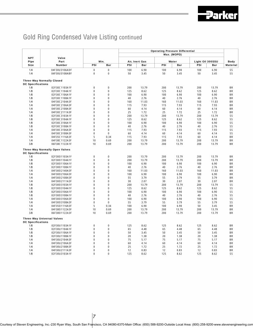
7
Operating Pressure DifferentialMax. (MOPD)
NPT ValvePipe Part Min. Air, Inert Gas Water Light Oil 300SSU BodySize Number PSI Bar PSI Bar PSI Bar PSI Bar Material
1/4 04F30U3106ADF 0 0 100 6.90 100 6.90 100 6.90 SS1/4 04F30U3108ABF 0 0 50 3.45 50 3.45 50 3.45 SS
Three-Way Normally ClosedDC Specifications
1/8 02F30C1103A1F 0 0 200 13.79 200 13.79 200 13.79 BR1/8 02F30C1104A1F 0 0 125 8.62 125 8.62 125 8.62 BR1/8 02F30C1106A1F 0 0 100 6.90 100 6.90 100 6.90 BR1/8 02F30C1108A1F 0 0 40 2.76 40 2.76 40 2.76 BR1/4 04F30C2104A3F 0 0 160 11.03 160 11.03 160 11.03 BR1/4 04F30C2106A3F 0 0 115 7.93 115 7.93 115 7.93 BR1/4 04F30C2108A3F 0 0 60 4.14 60 4.14 60 4.14 BR1/4 04F30C2111A3F 0 0 25 1.72 25 1.72 25 1.72 BR1/8 02F30C3103A1F 0 0 200 13.79 200 13.79 200 13.79 SS1/8 02F30C3104A1F 0 0 125 8.62 125 8.62 125 8.62 SS1/8 02F30C3106A1F 0 0 100 6.90 100 6.90 100 6.90 SS1/8 02F30C3108A1F 0 0 40 2.76 40 2.76 40 2.76 SS1/4 04F30C3106A3F 0 0 115 7.93 115 7.93 115 7.93 SS1/4 04F30C3108A3F 0 0 60 4.14 60 4.14 60 4.14 SS1/4 04F35C1116A3F 5 0.34 115 7.93 115 7.93 60 4.14 BR1/4 04F38C1122A3F 10 0.69 200 13.79 200 13.79 200 13.79 BR3/8 06F38C1122A1F 10 0.69 200 13.79 200 13.79 200 13.79 BR
Three-Way Normally Open ValvesDC Specifications
1/8 02F30O1103A1F 0 0 200 13.79 200 13.79 200 13.79 BR1/8 02F30O1104A1F 0 0 200 13.79 200 13.79 200 13.79 BR1/8 02F30O1106A1F 0 0 100 6.90 100 6.90 100 6.90 BR1/8 02F30O1108A1F 0 0 40 2.76 40 2.76 40 2.76 BR1/4 04F30O2140A3F 0 0 160 11.03 160 11.03 160 11.03 BR1/4 04F30O2106A3F 0 0 100 6.90 100 6.90 100 6.90 BR1/4 04F30O2108A3F 0 0 55 3.79 55 3.79 55 3.79 BR1/4 04F30O2111A3F 0 0 30 2.07 30 2.07 30 2.07 BR1/8 02F30O3103A1F 0 0 200 13.79 200 13.79 200 13.79 SS1/8 02F30O3104A1F 0 0 125 8.62 125 8.62 125 8.62 SS1/8 02F30O3106A1F 0 0 100 6.90 100 6.90 100 6.90 SS1/8 02F30O3108A1F 0 0 40 2.76 40 2.76 40 2.76 SS1/4 04F30O3106A3F 0 0 100 6.90 100 6.90 100 6.90 SS1/4 04F30O3108A3F 0 0 55 3.79 55 3.79 55 3.79 SS1/4 04F35O1116A3F 5 0.34 100 6.90 100 6.90 50 3.45 BR1/4 04F38O1122A3F 10 0.69 200 13.79 200 13.79 200 13.79 BR3/8 06F38O1122A3F 10 0.69 200 13.79 200 13.79 200 13.79 BR
Three-Way Universal ValvesDC Specifications
1/8 02F30U1103A1F 0 0 125 8.62 125 8.62 125 8.62 BR1/8 02F30U1104A1F 0 0 65 4.48 65 4.48 65 4.48 BR1/8 02F30U1106A1F 0 0 50 3.45 50 3.45 50 3.45 BR1/8 02F30U1108A1F 0 0 20 1.38 20 1.38 20 1.38 BR1/4 04F30U2104A3F 0 0 75 5.17 75 5.17 75 5.17 BR1/4 04F30U2106A3F 0 0 60 4.14 60 4.14 60 4.14 BR1/4 04F30U2108A3F 0 0 25 1.72 25 1.72 25 1.72 BR1/4 04F30U2111A3F 0 0 12 0.83 12 0.83 12 0.83 BR1/8 02F30U3103A1F 0 0 125 8.62 125 8.62 125 8.62 SS
Gold Ring Condensed Valve Listing continued
Courtesy of Steven Engineering, Inc.-230 Ryan Way, South San Francisco, CA 94080-6370-Main Office: (650) 588-9200-Outside Local Area: (800) 258-9200-www.stevenengineering.com

Gold Ring Condensed Valve Listing continuedGold Ring Condensed Valve Listing continued
Operating Pressure DifferentialNPT Valve Max. (MOPD) Pipe Part Min. Cryogenic Fluids BodySize Number PSI Bar PSI Bar Material
Cryogenic Two-Way Normally Closed ValvesAC Specifications
1/4 04F20C2414CDF-L 0 0 70 4.83 BR3/8 06F20C2414CDF-L 0 0 70 4.83 BR1/2 08FH6C2440ACF-L 10 0.69 200 13.79 BR1/8 02F20C3503ABF-43 0 0 1000 68.97 SS
Operating Pressure DifferentialMax. (MOPD)
NPT ValvePipe Part Min. Max. BodySize Number PSI Bar PSI Bar Material
Two-Way Normally Closed Low Vacuum ValvesAC Specifications
1/4 04F20C2118AAF 0 0 15 1.03 BR3/8 06F20C2120AAF 0 0 15 1.03 BR1/2 08F20C2128ADF 0 0 15 1.03 BR3/4 12F20C2148ADF 0 0 4 0.28 BR3/4 12F23C2148ACF 0 0 15 1.03 BR1 16FH5C2164ADF 0 0 15 1.03 BR
Two-Way Normally Open Low Vacuum ValvesAC Specifications
3/8 06F23O2140ACF 0 0 15 1.03 BR1/2 08F23O2140ACF 0 0 15 1.03 BR3/4 12F23O2148ACF 0 0 15 1.03 BR
Two-Way Normally Closed Medium Vacuum ValvesAC Specifications
1/4 04F20C2118AAF-S 0 0 15 1.03 BR3/8 06F20C2120AAF-S 0 0 15 1.03 BR1/2 08F20C2128ADF-S 0 0 15 1.03 BR3/4 12F20C2148ADF-S 0 0 4 0.28 BR3/4 12F23C2140ACF-S 0 0 15 1.03 BR1 16FH5C2164ADF-S 0 0 15 1.03 BR
Operating Pressure DifferentialMax. (MOPD)
NPT ValvePipe Part Min. Air, Inert Gas Water Light Oil 300SSU BodySize Number PSI Bar PSI Bar PSI Bar PSI Bar Material
1/8 02F30U3104A1F 0 0 65 4.48 65 4.48 65 4.48 SS1/8 02F30U3106A1F 0 0 50 3.45 50 3.45 50 3.45 SS1/8 02F30U3108A1F 0 0 20 1.38 20 1.38 20 1.38 SS1/4 04F30U3106A3F 0 0 60 4.14 60 4.14 60 4.14 SS1/4 04F30U3108A3F 0 0 25 1.72 25 1.72 25 1.72 SS
Four- Way Two Position ValvesAC Specifications
1/4 04F48S2106ACF 10 0.69 150 10.34 150 10.34 150 10.34 BR
Four-Way Two Position ValvesDC Specifications
1/4 04F48S2106A3F 10 0.69 100 6.90 100 6.90 100 6.90 BR
8
Courtesy of Steven Engineering, Inc.-230 Ryan Way, South San Francisco, CA 94080-6370-Main Office: (650) 588-9200-Outside Local Area: (800) 258-9200-www.stevenengineering.com

Operating Pressure DifferentialMax. (MOPD)
NPT ValvePipe Part Min. Max.
BodySize Number PSI Bar PSI Bar Material
Two-Way Normally Open Medium Vacuum ValvesAC Specifications
3/8 06F23O2140ACF-S 0 0 15 1.03 BR1/2 08F23O2140ACF-S 0 0 15 1.03 BR3/4 12F23O2148ACF-S 0 0 15 1.03 BR
Two-Way Normally Closed High Vacuum ValvesAC Specifications
1/4 04F20C2218AAF-V 0 0 15 1.03 BR3/8 06F20C2220AAF-V 0 0 15 1.03 BR1/2 08F20C2228ADF-V 0 0 15 1.03 BR3/4 12F20C2248ADF-V 0 0 4 0.28 BR3/4 12F23C2248ACF-V 0 0 15 1.03 BR1 16FH5C2264ADF-V 0 0 15 1.03 BR
Two-Way Normally Open High Vacuum ValvesAC Specifications
3/8 06F23O2240ACF-V 0 0 15 1.03 BR1/2 08F23O2240ACF-V 0 0 15 1.03 BR3/4 12F23O2248ACF-V 0 0 15 1.03 BR
9
Gold Ring Condensed Valve Listing continued
Courtesy of Steven Engineering, Inc.-230 Ryan Way, South San Francisco, CA 94080-6370-Main Office: (650) 588-9200-Outside Local Area: (800) 258-9200-www.stevenengineering.com

Gold Ring Type I General Purpose, Splice Box, Conduit Hub and Type 4X, Gold Ring IIunit solenoids and unit valves can be orderedseparately for maximum inventory flexibility.No prefix or suffix required to order standardfeatures.
To Order
Step 1: Select the Gold Ring valverequired by using the appropriate valvespecification table.
Step 2: Select one enclosure code, onecoil termination code and one voltage code.Standard leads are 18-inches long with allenclosures, except splice box where 6-inchleads are standard.
Step 3: When separate valve andsolenoid, the last two digits of the valvemust match the first two digits of thesolenoid.
Example: Valve: 04F20C1103AAFSolenoid: AF 4C05
Step 4: OOppeenn ffrraammee aanndd TTyyppeess 66,, 77 aanndd99 mmuusstt bbee oorrddeerreedd ffaaccttoorryy aasssseemmbblleedd..
Solenoid Enclosure and Coil Information
Surrounding the coil is the metal solenoidenclosure and frame. Together with theplunger and pole piece, it forms themagnetic circuit that operates the valve.Without the enclosure, the magnetic circuitis not complete. Without a completemagnetic circuit, the magnetic field isreduced and valve performance suffers.
The enclosure also protects the coil fromthe environment. Solenoid enclosures comein a range of constructions offering varyinglevels of protection against the elements andother forces. NEMA identifies the differentenclosures as “Types” and sets standards fortheir safety and performance. Following is adescription of Gold Ring solenoid valveenclosures.
The National Electrical ManufacturersAssociation (NEMA) recommends suitablematerials and components to meet eachenclosure type. The enclosures listed herewill only meet the applicable NEMArecommendations when properly installedand operated to NEMA specifications and inaccordance with the NEC.
Ordering Information
10
Sc
rew
(K)
Sp
ad
e (
S)
DIN
(H
)
18
”
Le
ad
s
Condensed Listingof NEMA Enclosures
NEMA Type Gold Ring Enclosure Code1 P,S2 43 4
3R 43S 44 P*,4
4X 46 W7 E,M,Y,Z9 E,M,Y,Z
* With suitable connector
Enclosure/Coil Termination CombinationsCoil Termination
EnclosuresGold Ring II (4) 4 XExplosion-Proof (E) X316 SS Explosion-Proof (M ) XOpen Frame (O) O X X XEncapsulated DIN (P) p XSplice Box (S) S X316 SS Submersible (U) XSubmersible Splice Box (W) W X X XExplosion-Proof W/Ground Lead (Y) X
6”
Le
ad
s
EnclosureCode
Courtesy of Steven Engineering, Inc.-230 Ryan Way, South San Francisco, CA 94080-6370-Main Office: (650) 588-9200-Outside Local Area: (800) 258-9200-www.stevenengineering.com

Solenoid EnclosuresType 1, 2, 3, 3R, 3S, 4 and 4X: Gold Ring II
These completely encapsulated solenoids are suitable Gold Ring II, Types 1, 2, 3,for Type 1; Type 2– indoor installations to provide 3R, 3S, 4, 4Xprotection against splashing; Type 3– outdoor installations for protection against rain, snow, sleet and dust; Type 3R; Type 3S; Type 4, watertight and dusttight; and Type 4X, corrosion resistant.
Open Frame
OOppeenn FFrraammee enclosures are unclassified by NEMA. Material Specifications: Spade/ScrewThe solenoid is open on two or more sides. They are • Formed Sheet Carbon Steel:used where space is limited and protection is afforded SAE 1008-1010by mounting the solenoid in an approved panel box or • Zinc Plated Gold Color: other protective enclosure. Available with panel Federal Specification QQ-Z-325mount construction.
Type 1: General Purpose
Type 1 General Purpose enclosures are designed for Material Specifications: General Purpose, Type 1 Splice Boxindoor use to provide moderate protection against • Formed Sheet Carbon Steel: contact with other equipment. SAE 1008-1010
• Zinc Plated Gold Color:Federal Specification QQ-Z-325
Splice Box enclosures provide an integral splice box to • Black Epoxy Coating on accommodate the coil leads and incoming wires. GalvanizationThe splice box has two standard knock-outs, one on each side.
Type 6: Submersible, Watertight, Dusttight and Sleet-Resistant
Indoor and Outdoor, Type 6 enclosures protect the coil NEMA 6 Splice Boxagainst occasional submersion (6 ft. for 30 minutes)dust; splashing, seeping, falling or hose-directed water;external condensation; and lint.
11Courtesy of Steven Engineering, Inc.-230 Ryan Way, South San Francisco, CA 94080-6370-Main Office: (650) 588-9200-Outside Local Area: (800) 258-9200-www.stevenengineering.com

Connector Kits For DIN CoilsPart No.1/2” conduit connector SA06-0056-10mm cable gland connector SA06-004
Each kit contains a gasket and attaching screw.Contact factory for timer information.
Solenoid Enclosures continued
DIN Connector
DIN Connector coils meet ISO4400/DIN 43650 A DIN
requirements.
Type 7: Explosion-Proof for Indoor Hazardous LocationsType 9: Dust-Ignition Proof
Type 7 Explosion-Proof enclosures are designed for use Material Specifications: Type 7, 9in gas or vapor atmospheres. Type 9 enclosures prevent Splice Box or Explosion-Proofexplosive amounts of dust from metal, coal, coke, flour, Aluminum Cast: ASTM SC84Astarch or grain from entering the enclosure. Black Epoxy Coating
Explosion-Proof : 316 Stainless Steel Investment Cast: ACI CF-8M NEMA Classifications: Type 7 Class 1 Division 1 Group C and D Type 7, 9 Stainless Steel Type 9 Class 2 Division 1 Group E,F,G
A, B & 1WATTAGES
C, D & 3WATTAGES
ABCD
7/16 9/161-1/2 1-3/41-3/8 1-9/161-5/8 1-7/8
12
Courtesy of Steven Engineering, Inc.-230 Ryan Way, South San Francisco, CA 94080-6370-Main Office: (650) 588-9200-Outside Local Area: (800) 258-9200-www.stevenengineering.com

Two-Way Valve Contents
Gold Ring Two-Way Valve Specifications............13-32
Series 20, Direct Acting ..................................14-18Series 20, Low Pressure ..................................19-20Series 22, 23, 24, 28 Pilot Operated .............. 21-24Series 25, H5 Pivoted Edge ............................ 25-27Hot Water and Steam...................................... 28-30Series 28, High Pressure ................................ 31-32
Courtesy of Steven Engineering, Inc.-230 Ryan Way, South San Francisco, CA 94080-6370-Main Office: (650) 588-9200-Outside Local Area: (800) 258-9200-www.stevenengineering.com

MechanicalCharacteristics
Standard Materials of Construction• Body-Brass, 303 Stainless Steel, 316 Stainless
Steel as listed• Seals-NBR or Urethane as listed• Plunger and Pole Piece-430FR Stainless Steel• Plunger Tube-305 Stainless Steel• Springs-302 Stainless Steel• Shading Coil-Copper(Brass Bodies),
Silver(Stainless Steel Bodies)• Disc Holder-1/8-inch NPT Celcon,
1/4-inch Ryton
Compatible Fluids• Gases, Fluid, Light Oils, or Vacuum from 760-23
Torr (29” Mercury) and other clean flowingmedia compatible with brass or stainless steel
Electrical Characteristics
Voltages• DC, 12, 24 (other voltages available upon
request)• AC-24/60, 110/120-50/60, 220/240-50/60,
Coil• Class F Standard, Class H Available
Agency Approvals• Standard valves with general purpose or
explosion proof solenoid enclosures are ULListed and CSA Certified. For details, consult factory.
Miscellaneous
Temperature Ratings (media as listed)• AC Voltages: 200°F max.• DC Voltages: 150°F max.• Ambient: 32-77°F (standard)• For temperature variations, consult the factory.
Installation• Series 20 valves may be mounted in any
position. Product and mounting dimensionsshown are nominal.
Applications• Used in a variety of applications including:
Material Transfer, Molding, Vending Machines,Instrumentation, Welding Equipment, WaterTreatment Systems, Spray Equipment, DentalEquipment, Laundry Equipment, Food Processing Machinery.
SPECIFICATIONS
GOLD RING Series 20 Small Two-Way Direct Acting Valves
* Valve is standard with urethane disc.
14Two-
Way
Sol
enoi
d Va
lves
DIRECT ACTING BRASS VALVES – NORMALLY CLOSED (ENERGIZE TO OPEN), NBR SEALSAC VALVE SPECIFICATIONS
Orifice Diameter Flow Factor Operating Pressure Differential Max. Temp.NPT Max. (MOPD) ValvePipe Min. Air, Inert Gas Water Light Oil 300SSU AC Const. PartSize inch mm Cv Kv (PSI/Bar) (PSI/BAR) (PSI/Bar) (PSI/BAR) °F °C Watt Ref. Number
1/8 3/64 1.19 .06 0.05 0 750 51.72 750 51.72 530 36.55 180 82 6.0 1 02F20C1103AAF1/8 3/32 2.38 .20 0.17 0 275 18.97 290 20.00 130 8.97 180 82 6.0 1 02F20C1106AAF1/8 1/8 3.18 .34 0.29 0 155 10.69 180 12.41 140 9.66 180 82 6.0 1 02F20C1108AAF1/4 3/64 1.19 .06 0.05 0 750 51.72 750 51.72 500 34.48 180 82 6.0 2 04F20C1103AAF1/4 3/64 1.19 .06 0.05 0 1500 103.45 1500 103.45 1100 75.86 140 60 11.0 3 04F20C1503ACF*1/4 3/32 2.38 .17 0.15 0 360 24.83 340 23.45 160 11.03 180 82 6.0 2 04F20C1106AAF1/4 1/8 3.18 .35 0.30 0 140 9.66 165 11.38 90 6.21 180 82 6.0 2 04F20C1108AAF1/4 1/8 3.18 .35 0.30 0 300 20.69 300 20.69 200 13.79 180 82 11.0 3 04F20C1108ACF1/4 5/32 3.97 .50 0.43 0 150 10.34 150 10.34 145 10.00 180 82 11.0 5 04F20C2110ACF1/4 7/32 5.56 .85 0.73 0 40 2.76 50 3.45 40 2.76 180 82 6.0 4 04F20C2114AAF1/4 7/32 5.56 .72 0.62 0 100 6.90 100 6.90 100 6.90 180 82 16.0 5 04F20C2114BDF1/4 9/32 7.14 .96 0.83 0 27 1.86 36 2.48 28 1.93 180 82 6.0 4 04F20C2118AAF1/4 9/32 7.14 .88 0.76 0 90 6.21 80 5.52 80 5.52 200 93 16.0 5 04F20C2118BDF3/8 1/8 3.18 .35 0.30 0 160 11.03 150 10.34 90 6.21 180 82 6.0 6 06F20C2108AAF3/8 5/32 3.97 .52 0.45 0 150 10.34 150 10.34 145 10.00 180 82 11.0 7 06F20C2110ACF3/8 7/32 5.56 .72 0.62 0 100 6.90 100 6.90 100 6.90 200 93 16.0 7 06F20C2114BDF3/8 9/32 7.14 .85 0.73 0 90 6.21 80 5.52 80 5.52 200 93 16.0 7 06F20C2118BDF
Courtesy of Steven Engineering, Inc.-230 Ryan Way, South San Francisco, CA 94080-6370-Main Office: (650) 588-9200-Outside Local Area: (800) 258-9200-www.stevenengineering.com

Two-
Way
Sol
enoi
d Va
lves
15
To choose a solenoid for your valve, referto the AC or DC chart found on the flapattached to the back cover of this catalog.
DIRECT ACTING BRASS VALVES – NORMALLY CLOSED (ENERGIZE TO OPEN), NBR SEALSDC VALVE SPECIFICATIONS
Orifice Diameter Flow Factor Operating Pressure Differential Max. Temp.NPT Max. (MOPD) ValvePipe Min. Air, Inert Gas Water Light Oil 300SSU DC Const. PartSize inch mm Cv Kv (PSI/Bar) (PSI/BAR) (PSI/Bar) (PSI/BAR) °F °C Watt Ref. Number
1/8 3/64 1.19 .06 0.05 0 500 34.48 500 34.48 500 34.48 120 49 9.5 1 02F20C1103A1F1/8 3/32 2.38 .20 0.17 0 150 10.34 140 9.66 145 10.00 120 49 9.5 1 02F20C1106A1F1/8 1/8 3.18 .34 0.29 0 80 5.52 80 5.52 80 5.52 120 49 9.5 1 02F20C1108A1F1/4 3/32 2.38 .17 0.15 0 150 10.34 125 8.62 125 8.62 120 49 9.5 2 04F20C1106A1F1/4 1/8 3.18 .35 0.30 0 75 5.17 70 4.83 70 4.83 150 66 11.5 3 04F20C1108A3F3/8 1/8 3.18 .35 0.30 0 75 5.17 70 4.83 70 4.83 150 66 11.5 7 06F20C2108A3F3/8 5/32 3.97 .52 0.45 0 35 2.41 35 2.41 35 2.41 150 66 11.5 7 06F20C2110A3F3/8 7/32 5.56 .72 0.62 0 25 1.72 25 1.72 25 1.72 150 66 11.5 7 06F20C2114A3F3/8 9/32 7.14 .85 0.73 0 14 0.97 14 0.97 14 0.97 120 49 9.5 6 06F20C2118A1F
DIRECT ACTING BRASS VALVES – NORMALLY OPEN (ENERGIZE TO CLOSE), NBR SEALSAC VALVE SPECIFICATIONS
Orifice Diameter Flow Factor Operating Pressure Differential Max. Temp.NPT Max. (MOPD) ValvePipe Min. Air, Inert Gas Water Light Oil 300SSU AC Const. PartSize inch mm Cv Kv (PSI/Bar) (PSI/BAR) (PSI/Bar) (PSI/BAR) °F °C Watt Ref. Number
1/8 1/16 1.59 .09 0.08 0 500 34.48 300 20.69 225 15.52 180 82 10.2 8 02F20O1104ABF1/8 3/32 2.38 .15 0.13 0 275 18.97 200 13.79 150 10.34 180 82 6.0 8 02F20O1106AAF1/8 1/8 3.18 .21 0.18 0 125 8.62 100 6.90 85 5.86 180 82 6.0 8 02F20O1108AAF1/4 3/32 2.38 .17 0.15 0 300 20.69 250 17.24 230 15.86 180 82 11.0 9 04F20O1106ACF1/4 1/8 3.18 .35 0.30 0 130 8.97 110 7.59 100 6.90 180 82 11.0 9 04F20O1108ACF1/4 9/32 7.14 .96 0.83 0 30 2.07 25 1.72 20 1.38 180 82 11.0 10 04F20O2118ACF
DIRECT ACTING BRASS VALVES – NORMALLY OPEN (ENERGIZE TO CLOSE), NBR SEALSDC VALVE SPECIFICATIONS
Orifice Diameter Flow Factor Operating Pressure Differential Max. Temp.NPT Max. (MOPD) ValvePipe Min. Air, Inert Gas Water Light Oil 300SSU DC Const. PartSize inch mm Cv Kv (PSI/Bar) (PSI/BAR) (PSI/Bar) (PSI/BAR) °F °C Watt Ref. Number
1/8 1/16 1.59 .09 0.08 0 400 27.59 250 17.24 150 10.34 120 49 9.5 8 02F20O1104A1F1/8 3/32 2.38 .15 0.13 0 190 13.10 110 7.59 110 7.59 120 49 9.5 8 02F20O1106A1F1/8 1/8 3.18 .21 0.18 0 80 5.52 60 4.14 50 3.45 120 49 9.5 8 02F20O1108A1F1/4 3/64 1.19 .06 0.05 0 500 34.48 500 34.48 500 34.48 140 60 11.5 9 04F20O1103A3F1/4 1/8 3.18 .35 0.30 0 80 5.52 60 4.14 60 4.14 150 66 11.5 9 04F20O1108A3F
Courtesy of Steven Engineering, Inc.-230 Ryan Way, South San Francisco, CA 94080-6370-Main Office: (650) 588-9200-Outside Local Area: (800) 258-9200-www.stevenengineering.com

DIRECT ACTING STAINLESS STEEL VALVES – NORMALLY CLOSED (ENERGIZE TO OPEN), NBR SEALSAC VALVE SPECIFICATIONS
Orifice Diameter Flow Factor Operating Pressure Differential Max. Temp.NPT Max. (MOPD) ValvePipe Min. Air, Inert Gas Water Light Oil 300SSU AC Const. PartSize inch mm Cv Kv (PSI/Bar) (PSI/BAR) (PSI/Bar) (PSI/BAR) °F °C Watt Ref. Number
1/8 3/64 1.19 .06 0.05 0 750 51.72 750 51.72 530 36.55 180 82 6.0 1 02F20C3103AAF1/8 3/32 2.38 .20 0.17 0 275 18.97 290 20.00 130 8.97 180 82 6.0 1 02F20C3106AAF1/8 1/8 3.18 .34 0.29 0 155 10.69 180 12.41 140 9.66 180 82 6.0 1 02F20C3108AAF3/8 1/8 3.18 .35 0.30 0 160 11.03 150 10.34 90 6.21 180 82 6.0 6 06F20C6108AAF3/8 1/8 3.18 .35 0.30 0 310 21.38 310 21.38 260 17.93 200 93 16.0 7 06F20C6108ADF
* Valve is standard with urethane disc.
Two-
Way
Sol
enoi
d Va
lves
16
Small Two-Way Direct Acting ValvesSeries 20
DIRECT ACTING STAINLESS STEEL VALVES – NORMALLY OPEN (ENERGIZE TO CLOSE), NBR SEALSAC VALVE SPECIFICATIONS
Orifice Diameter Flow Factor Operating Pressure Differential Max. Temp.NPT Max. (MOPD) ValvePipe Min. Air, Inert Gas Water Light Oil 300SSU AC Const. PartSize inch mm Cv Kv (PSI/Bar) (PSI/BAR) (PSI/Bar) (PSI/BAR) °F °C Watt Ref. Number
1/8 1/16 1.59 .09 0.08 0 500 34.48 300 20.69 225 15.52 180 82 10.2 8 02F20O3104ABF1/8 3/32 2.38 .15 0.13 0 275 18.97 200 13.79 150 10.34 180 82 6.0 8 02F20O3106AAF1/8 1/8 3.18 .21 0.18 0 125 8.62 100 6.90 85 5.86 180 82 6.0 8 02F20O3108AAF1/4 1/8 3.18 .35 0.30 0 130 8.97 110 7.59 100 6.90 200 93 11.0 13 04F20O3108ACF1/4 5/32 3.97 .50 0.43 0 85 5.86 75 5.17 60 4.14 200 93 11.0 13 04F20O3110ACF
Courtesy of Steven Engineering, Inc.-230 Ryan Way, South San Francisco, CA 94080-6370-Main Office: (650) 588-9200-Outside Local Area: (800) 258-9200-www.stevenengineering.com

DIRECT ACTING STAINLESS STEEL VALVES – NORMALLY CLOSED (ENERGIZE TO OPEN), NBR SEALSDC VALVE SPECIFICATIONS
Orifice Diameter Flow Factor Operating Pressure Differential Max. Temp.NPT Max. (MOPD) ValvePipe Min. Air, Inert Gas Water Light Oil 300SSU DC Const. PartSize inch mm Cv Kv (PSI/Bar) (PSI/BAR) (PSI/Bar) (PSI/BAR) °F °C Watt Ref. Number
1/8 3/64 1.19 .06 0.05 0 500 34.48 500 34.48 500 34.48 120 49 9.5 1 02F20C3103A1F1/8 3/32 2.38 .20 0.17 0 150 10.34 140 9.66 145 10.00 120 49 9.5 1 02F20C3106A1F1/8 1/8 3.18 .34 0.29 0 80 5.52 80 5.52 80 5.52 120 49 9.5 1 02F20C3108A1F3/8 1/8 3.18 .35 0.30 0 65 4.48 60 4.14 60 4.14 120 49 9.5 6 06F20C6108A1F3/8 5/32 3.97 .52 0.45 0 35 2.41 35 2.41 35 2.41 150 66 11.5 7 06F20C6110A3F3/8 7/32 5.56 .72 0.62 0 25 1.72 25 1.72 25 1.72 150 66 11.5 7 06F20C6114A3F3/8 9/32 7.14 .85 0.73 0 18 1.24 15 1.03 18 1.24 150 66 11.5 7 06F20C6118A3F
Two-
Way
Sol
enoi
d Va
lves
17
To choose a solenoid for your valve, referto the AC or DC chart found on the flapattached to the back cover of this catalog.
#4, 5, 10
DR
AWIN
GS
#6, 7
DIRECT ACTING STAINLESS STEEL VALVES – NORMALLY OPEN (ENERGIZE TO CLOSE), NBR SEALSDC VALVE SPECIFICATIONS
Orifice Diameter Flow Factor Operating Pressure Differential Max. Temp.NPT Max. (MOPD) ValvePipe Min. Air, Inert Gas Water Light Oil 300SSU DC Const. PartSize inch mm Cv Kv (PSI/Bar) (PSI/BAR) (PSI/Bar) (PSI/BAR) °F °C Watt Ref. Number
1/8 1/16 1.59 .09 0.08 0 400 27.59 250 17.24 150 10.34 120 49 9.5 8 02F20O3104A1F1/8 3/32 2.38 .15 0.13 0 190 13.10 110 7.59 110 7.59 120 49 9.5 8 02F20O3106A1F1/8 1/8 3.18 .21 0.18 0 80 5.52 60 4.14 50 3.45 120 49 9.5 8 02F20O3108A1F1/4 1/8 3.18 .35 0.30 0 80 5.52 60 4.14 60 4.14 150 66 11.5 13 04F20O3108A3F
Courtesy of Steven Engineering, Inc.-230 Ryan Way, South San Francisco, CA 94080-6370-Main Office: (650) 588-9200-Outside Local Area: (800) 258-9200-www.stevenengineering.com

18Two-
Way
Sol
enoi
d Va
lves
#2, 3, 9 Bottom
#11, 12, 13 Bottom
#1, 2, 3, 9, 11, 12, 13#8
Series 20 Small Two-Way Direct Acting Valves
Courtesy of Steven Engineering, Inc.-230 Ryan Way, South San Francisco, CA 94080-6370-Main Office: (650) 588-9200-Outside Local Area: (800) 258-9200-www.stevenengineering.com

Two-
Way
Sol
enoi
d Va
lves
19
To choose a solenoid for your valve, referto the AC or DC chart found on the flapattached to the back cover of this catalog.
DIRECT ACTING BRASS VALVES – NORMALLY OPEN (ENERGIZE TO CLOSE), NBR SEALSAC VALVE SPECIFICATIONS
Orifice Diameter Flow Factor Operating Pressure Differential Max. Temp.NPT Max. (MOPD) ValvePipe Min. Air, Inert Gas Water Light Oil 300SSU AC Const. PartSize inch mm Cv Kv (PSI/Bar) (PSI/BAR) (PSI/Bar) (PSI/BAR) °F °C Watt Ref. Number
3/8 5/16 7.94 1.10 0.95 0 15 1.03 15 1.03 - - 200 93 16.0 19 06F20O2120ADF1/2 7/16 11.11 2.20 1.90 0 15 1.03 15 1.03 - - 200 93 16.0 20 08F20O2128ADF3/4 3/4 19.05 5.50 4.74 0 2 0.14 2 0.14 - - 180 82 11.0 21 12F20O2148ACF
DIRECT ACTING BRASS VALVES – NORMALLY CLOSED (ENERGIZE TO OPEN), NBR SEALSAC VALVE SPECIFICATIONS
Orifice Diameter Flow Factor Operating Pressure Differential Max. Temp.NPT Max. (MOPD) ValvePipe Min. Air, Inert Gas Water Light Oil 300SSU AC Const. PartSize inch mm Cv Kv (PSI/Bar) (PSI/BAR) (PSI/Bar) (PSI/BAR) °F °C Watt Ref. Number
3/8 5/16 7.94 1.10 0.95 0 15 1.03 12 0.83 - - 180 82 6.0 14 06F20C2120AAF3/8 5/16 7.94 1.10 0.95 0 20 1.38 20 1.38 - - 180 82 11.0 15 06F20C2120ACF1/2 7/16 11.11 2.80 2.41 0 4 0.28 6 0.41 - - 180 82 6.0 16 08F20C2128AAF1/2 7/16 11.11 2.80 2.41 0 15 1.03 15 1.03 - - 200 93 16.0 17 08F20C2128ADF3/4 3/4 19.05 5.00 4.31 0 4 0.28 4 0.28 - - 180 82 16.0 18 12F20C2148ADF
MechanicalCharacteristics
Standard Materials of Construction• Body-Brass, 303 Stainless Steel, 316 Stainless
Steel as listed• Seals-NBR • Plunger and Pole Piece-430FR Stainless Steel• Plunger Tube-305 Stainless Steel• Springs-302 Stainless Steel• Shading Coil-Copper (Brass Bodies),
Silver (Stainless Steel Bodies)• Plunger Rod & Plate-303 Stainless Steel
Compatible Fluids• Gases, Fluid, Light Oils and other clean flowing
media compatible with brass or stainless steel
Electrical Characteristics
Voltages• DC, 12, 24, other voltages available upon
request)• AC-24/60, 110/120-50/60, 220/240-50/60,
Coil• Class F Standard, Class H Available
Agency Approvals• Standard valves with general purpose or
explosion proof solenoid enclosures are ULListed and CSA Certified. For details, consult factory.
Miscellaneous
Temperature Ratings (media as listed)• AC Voltages: 200°F max.• DC Voltages: 180°F max.• Ambient: 32-77°F (standard)• For temperature variations, consult the factory.
Installation• Low Pressure Series 20 should be mounted
vertical and upright. See mounting dimensions(nominal) shown here.
Applications• Used in a variety of applications including: Low
Pressure Systems (gases, fluids, light oils),Vacuum Systems 760-25 Torr (29” Mercury)-(molding, collating, material transfer).
SPECIFICATIONS
GOLD RING Series 20 Low Pressure Two-Way Direct Acting Valves
These are high flow, direct acting, low pressure valves. Please verify system pressure before installing.
Important: For proper operation, do not exceed maximum rated pressure.
DIRECT ACTING STAINLESS STEEL VALVES – NORMALLY CLOSED (ENERGIZE TO OPEN), NBR SEALSAC VALVE SPECIFICATIONS
Orifice Diameter Flow Factor Operating Pressure Differential Max. Temp.NPT Max. (MOPD) ValvePipe Min. Air, Inert Gas Water Light Oil 300SSU AC Const. PartSize inch mm Cv Kv (PSI/Bar) (PSI/BAR) (PSI/Bar) (PSI/BAR) °F °C Watt Ref. Number
3/8 5/16 7.94 1.10 0.95 0 20 1.38 20 1.38 - - 180 82 11.0 15 06F20C6120ACF1/2 7/16 11.11 2.80 2.41 0 15 1.03 15 1.03 - - 200 93 16.0 17 08F20C6128ADF3/4 3/4 19.05 6.00 5.17 0 4 0.28 4 0.28 - - 180 82 16.0 18 12F20C6148ADF
Courtesy of Steven Engineering, Inc.-230 Ryan Way, South San Francisco, CA 94080-6370-Main Office: (650) 588-9200-Outside Local Area: (800) 258-9200-www.stevenengineering.com

20Two-
Way
Sol
enoi
d Va
lves
DIRECT ACTING STAINLESS STEEL VALVES – NORMALLY CLOSED (ENERGIZE TO OPEN), NBR SEALSDC VALVE SPECIFICATIONS
Orifice Diameter Flow Factor Operating Pressure Differential Max. Temp.NPT Max. (MOPD) ValvePipe Min. Air, Inert Gas Water Light Oil 300SSU DC Const. PartSize inch mm Cv Kv (PSI/Bar) (PSI/BAR) (PSI/Bar) (PSI/BAR) °F °C Watt Ref. Number
3/8 5/16 7.94 1.10 0.95 0 3.0 0.21 3.0 0.21 - - 150 66 11.5 15 06F20C6120A3F1/2 7/16 11.11 2.8 2.41 0 3 0.21 3 0.21 - - 180 82 11.5 17 08F20C6128A3F
DIRECT ACTING BRASS VALVES – NORMALLY OPEN (ENERGIZE TO CLOSE), NBR SEALSDC VALVE SPECIFICATIONS
Orifice Diameter Flow Factor Operating Pressure Differential Max. Temp.NPT Max. (MOPD) ValvePipe Min. Air, Inert Gas Water Light Oil 300SSU DC Const. PartSize inch mm Cv Kv (PSI/Bar) (PSI/BAR) (PSI/Bar) (PSI/BAR) °F °C Watt Ref. Number
3/8 5/16 7.94 1.10 0.95 0 5 0.34 3 0.21 - - 180 82 11.5 19 06F20O2120A3F1/2 7/16 11.11 2.20 1.90 0 1.5 0.10 1 0.07 - - 180 82 11.5 20 08F20O2128A3F
DIRECT ACTING BRASS VALVES – NORMALLY CLOSED (ENERGIZE TO OPEN), NBR SEALSDC VALVE SPECIFICATIONS
Orifice Diameter Flow Factor Operating Pressure Differential Max. Temp.NPT Max. (MOPD) ValvePipe Min. Air, Inert Gas Water Light Oil 300SSU DC Const. PartSize inch mm Cv Kv (PSI/Bar) (PSI/BAR) (PSI/Bar) (PSI/BAR) °F °C Watt Ref. Number
3/8 5/16 7.94 1.10 0.95 0 3 0.21 3 0.21 - - 120 49 9.5 14 06F20C2120A1F3/8 5/16 7.94 1.10 0.95 0 9 0.62 9 0.62 - - 120 49 11.5 15 06F20C2120A3F1/2 7/16 11.11 2.80 2.41 0 3 0.21 3 0.21 - - 180 82 11.5 17 08F20C2128A3F
#14, 15, 19
DR
AWIN
GS
#16, 17, 18, 20, 21
Series 20 Low Pressure Two-Way Direct Acting Valves
Courtesy of Steven Engineering, Inc.-230 Ryan Way, South San Francisco, CA 94080-6370-Main Office: (650) 588-9200-Outside Local Area: (800) 258-9200-www.stevenengineering.com
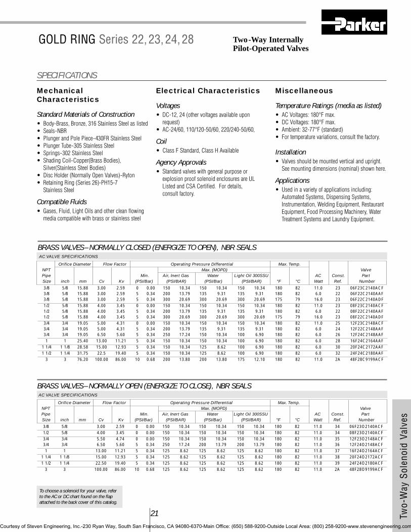
Two-
Way
Sol
enoi
d Va
lves
21
To choose a solenoid for your valve, referto the AC or DC chart found on the flapattached to the back cover of this catalog.
BRASS VALVES– NORMALLY OPEN (ENERGIZE TO CLOSE), NBR SEALSAC VALVE SPECIFICATIONS
Orifice Diameter Flow Factor Operating Pressure Differential Max. Temp.NPT Max. (MOPD) ValvePipe Min. Air, Inert Gas Water Light Oil 300SSU AC Const. PartSize inch mm Cv Kv (PSI/Bar) (PSI/BAR) (PSI/Bar) (PSI/BAR) °F °C Watt Ref. Number
3/8 5/8 3.00 2.59 0 0.00 150 10.34 150 10.34 150 10.34 180 82 11.0 34 06F23O2140ACF1/2 5/8 4.00 3.45 0 0.00 150 10.34 150 10.34 150 10.34 180 82 11.0 34 08F23O2140ACF3/4 3/4 5.50 4.74 0 0.00 150 10.34 150 10.34 150 10.34 180 82 11.0 35 12F23O2148ACF3/4 3/4 6.50 5.60 5 0.34 250 17.24 200 13.79 200 13.79 180 82 11.0 36 12F24O2148ACF1 1 13.00 11.21 5 0.34 125 8.62 125 8.62 125 8.62 180 82 11.0 37 16F24O2164ACF
1 1/4 1 1/8 15.00 12.93 5 0.34 125 8.62 125 8.62 125 8.62 180 82 11.0 38 20F24O2172ACF1 1/2 1 1/4 22.50 19.40 5 0.34 125 8.62 125 8.62 125 8.62 180 82 11.0 39 24F24O2180ACF
3 3 100.00 86.00 10 0.68 125 8.62 125 8.62 125 8.62 180 82 11.0 2A 48F28O9199ACF
MechanicalCharacteristics
Standard Materials of Construction• Body-Brass, Bronze, 316 Stainless Steel as listed• Seals-NBR • Plunger and Pole Piece-430FR Stainless Steel• Plunger Tube-305 Stainless Steel• Springs-302 Stainless Steel• Shading Coil-Copper(Brass Bodies),
Silver(Stainless Steel Bodies)• Disc Holder (Normally Open Valves)-Ryton• Retaining Ring (Series 26)-PH15-7
Stainless Steel
Compatible Fluids• Gases, Fluid, Light Oils and other clean flowing
media compatible with brass or stainless steel
Electrical Characteristics
Voltages• DC-12, 24 (other voltages available upon
request)• AC-24/60, 110/120-50/60, 220/240-50/60,
Coil• Class F Standard, Class H Available
Agency Approvals• Standard valves with general purpose or
explosion proof solenoid enclosures are ULListed and CSA Certified. For details, consult factory.
Miscellaneous
Temperature Ratings (media as listed)• AC Voltages: 180°F max.• DC Voltages: 180°F max.• Ambient: 32-77°F (standard)• For temperature variations, consult the factory.
Installation• Valves should be mounted vertical and upright.
See mounting dimensions (nominal) shown here.
Applications• Used in a variety of applications including:
Automated Systems, Dispensing Systems,Instrumentation, Welding Equipment, RestaurantEquipment, Food Processing Machinery, WaterTreatment Systems and Laundry Equipment.
SPECIFICATIONS
Two-Way Internally Pilot-Operated Valves
BRASS VALVES– NORMALLY CLOSED (ENERGIZE TO OPEN), NBR SEALSAC VALVE SPECIFICATIONS
Orifice Diameter Flow Factor Operating Pressure Differential Max. Temp.NPT Max. (MOPD) ValvePipe Min. Air, Inert Gas Water Light Oil 300SSU AC Const. PartSize inch mm Cv Kv (PSI/Bar) (PSI/BAR) (PSI/Bar) (PSI/BAR) °F °C Watt Ref. Number
3/8 5/8 15.88 3.00 2.59 0 0.00 150 10.34 150 10.34 150 10.34 180 82 11.0 23 06F23C2140ACF3/8 5/8 15.88 3.00 2.59 5 0.34 200 13.79 135 9.31 135 9.31 180 82 6.0 22 06F22C2140AAF3/8 5/8 15.88 3.00 2.59 5 0.34 300 20.69 300 20.69 300 20.69 175 79 16.0 23 06F22C2140ADF1/2 5/8 15.88 4.00 3.45 0 0.00 150 10.34 150 10.34 150 10.34 180 82 11.0 23 08F23C2140ACF1/2 5/8 15.88 4.00 3.45 5 0.34 200 13.79 135 9.31 135 9.31 180 82 6.0 22 08F22C2140AAF1/2 5/8 15.88 4.00 3.45 5 0.34 300 20.69 300 20.69 300 20.69 175 79 16.0 23 08F22C2140ADF3/4 3/4 19.05 5.00 4.31 0 0.00 150 10.34 150 10.34 150 10.34 180 82 11.0 25 12F23C2148ACF3/4 3/4 19.05 5.00 4.31 5 0.34 200 13.79 135 9.31 135 9.31 180 82 6.0 24 12F22C2148AAF3/4 3/4 19.05 6.50 5.60 5 0.34 250 17.24 150 10.34 100 6.90 180 82 6.0 26 12F24C2148AAF1 1 25.40 13.00 11.21 5 0.34 150 10.34 150 10.34 100 6.90 180 82 6.0 28 16F24C2164AAF
1 1/4 1 1/8 28.58 15.00 12.93 5 0.34 150 10.34 125 8.62 100 6.90 180 82 6.0 30 20F24C2172AAF1 1/2 1 1/4 31.75 22.5 19.40 5 0.34 150 10.34 125 8.62 100 6.90 180 82 6.0 32 24F24C2180AAF
3 3 76.20 100.00 86.00 10 0.68 200 13.80 200 13.80 175 12.10 180 82 11.0 2A 48F28C9199ACF
GOLD RING Series 22,23,24,28
Courtesy of Steven Engineering, Inc.-230 Ryan Way, South San Francisco, CA 94080-6370-Main Office: (650) 588-9200-Outside Local Area: (800) 258-9200-www.stevenengineering.com
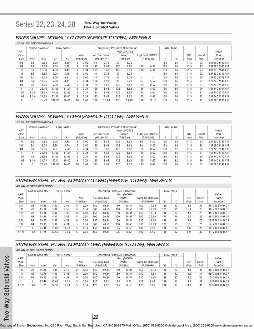
22Two-
Way
Sol
enoi
d Va
lves
BRASS VALVES– NORMALLY OPEN (ENERGIZE TO CLOSE), NBR SEALSDC VALVE SPECIFICATIONS
Orifice Diameter Flow Factor Operating Pressure Differential Max. Temp.NPT Max. (MOPD) ValvePipe Min. Air, Inert Gas Water Light Oil 300SSU DC Const. PartSize inch mm Cv Kv (PSI/Bar) (PSI/BAR) (PSI/Bar) (PSI/BAR) °F °C Watt Ref. Number
1/2 5/8 15.88 4.00 3.45 0 0.00 125 8.62 125 8.62 80 5.52 150 66 11.5 34 08F23O2140A3F3/4 3/4 19.05 5.50 4.74 0 0.00 125 8.62 125 8.62 80 5.52 150 66 11.5 35 12F23O2148A3F3/4 3/4 19.05 6.5 5.60 5 0.34 125 8.62 125 8.62 125 8.62 180 82 11.5 36 12F24O2148A3F1 1 25.40 13.00 11.21 5 0.34 125 8.62 125 8.62 125 8.62 180 82 11.5 37 16F24O2164A3F
1 1/4 1/8 28.58 15.00 12.93 5 0.34 125 8.62 125 8.62 125 8.62 180 82 11.5 38 20F24O2172A3F1 1/2 1 1/4 31.75 22.5 19.40 5 0.34 125 8.62 125 8.62 125 8.62 180 82 11.5 39 24F24O2180A3F
3 3 76.20 100.00 86.00 10 0.68 125 8.62 125 8.62 125 8.62 150 66 11.0 42 48F28O9199A3F
STAINLESS STEEL VALVES– NORMALLY CLOSED (ENERGIZE TO OPEN), NBR SEALSAC VALVE SPECIFICATIONS
Orifice Diameter Flow Factor Operating Pressure Differential Max. Temp.NPT Max. (MOPD) ValvePipe Min. Air, Inert Gas Water Light Oil 300SSU AC Const. PartSize inch mm Cv Kv (PSI/Bar) (PSI/BAR) (PSI/Bar) (PSI/BAR) °F °C Watt Ref. Number
3/8 5/8 15.88 3.00 2.59 0 0.00 150 10.34 150 10.34 150 10.34 180 82 11.0 23 06F23C6140ACF3/8 5/8 15.88 3.00 2.59 5 0.34 300 20.69 300 20.69 300 20.69 175 79 16.0 23 06F22C6140ADF1/2 5/8 15.88 4.00 3.45 0 0.00 150 10.34 150 10.34 150 10.34 180 82 11.0 23 08F23C6140ACF1/2 5/8 15.88 4.00 3.45 5 0.34 300 20.69 300 20.69 300 20.69 175 79 16.0 23 08F22C6140ADF3/4 3/4 19.05 5.00 4.31 0 0.00 150 10.34 150 10.34 150 10.34 180 82 11.0 25 12F23C6148ACF3/4 3/4 19.05 5.00 4.31 5 0.34 300 20.69 300 20.69 300 20.69 175 79 16 25 12F22C6148ADF1 1 25.40 13.00 11.21 5 0.34 150 10.34 125 8.62 100 6.90 180 82 6.0 28 16F24C6164AAF
1 1/2 1 1/4 31.75 22.50 19.40 5 0.34 150 10.34 125 8.62 100 6.90 180 82 6.0 32 24F24C6180AAF
STAINLESS STEEL VALVES– NORMALLY OPEN (ENERGIZE TO CLOSE), NBR SEALSAC VALVE SPECIFICATIONS
Orifice Diameter Flow Factor Operating Pressure Differential Max. Temp.NPT Max. (MOPD) ValvePipe Min. Air, Inert Gas Water Light Oil 300SSU AC Const. PartSize inch mm Cv Kv (PSI/Bar) (PSI/BAR) (PSI/Bar) (PSI/BAR) °F °C Watt Ref. Number
3/8 5/8 15.88 3.00 2.59 0 0.00 150 10.34 150 10.34 150 10.34 180 82 11.0 34 06F23O6140ACF1/2 1/2 12.70 4.00 3.45 0 0.00 150 10.34 150 10.34 150 10.34 180 82 11.0 34 08F23O6140ACF3/4 3/4 19.05 5.00 4.31 0 0.00 150 10.34 150 10.34 150 10.34 180 82 11.0 35 12F23O6148ACF1 1 25.40 13.00 11.21 5 0.34 125 8.62 125 8.62 125 8.62 180 82 11.0 37 16F24O6164ACF
1 1/2 1 1/4 31.75 22.50 19.40 5 0.34 125 8.62 125 8.62 125 8.62 180 82 11.0 39 24F24O6180ACF
BRASS VALVES– NORMALLY CLOSED (ENERGIZE TO OPEN), NBR SEALSDC VALVE SPECIFICATIONS
Orifice Diameter Flow Factor Operating Pressure Differential Max. Temp.NPT Max. (MOPD) ValvePipe Min. Air, Inert Gas Water Light Oil 300SSU DC Const. PartSize inch mm Cv Kv (PSI/Bar) (PSI/BAR) (PSI/Bar) (PSI/BAR) °F °C Watt Ref. Number
3/8 5/8 15.88 3.00 2.59 0 0.00 40 2.76 40 2.76 - 150 66 11.5 23 06F23C2140A3F3/8 5/8 15.88 3.00 2.59 5 0.34 125 8.62 100 6.90 100 6.90 150 66 11.5 23 06F22C2140A3F1/2 5/8 15.88 4.00 3.45 5 0.34 125 8.62 100 6.90 100 6.90 150 66 11.5 23 08F22C2140A3F1/2 5/8 15.88 4.00 3.45 0 0.00 40 2.76 40 2.76 - - 150 66 11.5 23 08F23C2140A3F3/4 3/4 19.05 5.00 4.31 0 0.00 40 2.76 40 2.76 - - 150 66 11.5 25 12F23C2148A3F3/4 3/4 19.05 5.00 4.31 5 0.34 100 6.90 90 6.21 75 5.17 150 66 11.5 27 12F24C2148A3F3/4 3/4 19.05 6.50 5.60 5 0.34 125 8.62 125 8.62 125 8.62 150 66 11.5 27 12F24C2148A3F1 1 25.40 13.00 11.21 5 0.34 125 8.62 125 8.62 125 8.62 150 66 11.5 29 16F24C2164A3F
1 1/4 1 1/8 28.58 15.00 12.93 5 0.34 125 8.62 125 8.62 125 8.62 150 66 11.5 31 20F24C2172A3F1 1/2 1 1/4 31.75 22.50 19.40 5 0.34 125 8.62 125 8.62 125 8.62 150 66 11.5 33 24F24C2180A3F
3 3 76.20 100.00 86.00 10 0.68 190 13.10 190 13.10 170 11.70 150 66 11.5 42 48F28C9199A3F
Series 22, 23, 24, 28 Two-Way Internally Pilot-Operated Valves
Courtesy of Steven Engineering, Inc.-230 Ryan Way, South San Francisco, CA 94080-6370-Main Office: (650) 588-9200-Outside Local Area: (800) 258-9200-www.stevenengineering.com

Two-
Way
Sol
enoi
d Va
lves
23
To choose a solenoid for your valve, referto the AC or DC chart found on the flapattached to the back cover of this catalog.
STAINLESS STEEL VALVES– NORMALLY CLOSED (ENERGIZE TO OPEN), NBR SEALSDC VALVE SPECIFICATIONS
Orifice Diameter Flow Factor Operating Pressure Differential Max. Temp.NPT Max. (MOPD) ValvePipe Min. Air, Inert Gas Water Light Oil 300SSU DC Const. PartSize inch mm Cv Kv (PSI/Bar) (PSI/BAR) (PSI/Bar) (PSI/BAR) °F °C Watt Ref. Number
3/8 5/8 15.88 3.00 2.59 0 0.00 40 2.76 40 2.76 - - 150 66 11.5 23 06F23C6140A3F3/8 5/8 15.88 3.00 2.59 5 0.34 125 8.62 100 6.90 100 6.90 150 66 11.5 23 06F22C6140A3F1/2 5/8 15.88 4.00 3.45 0 0.00 40 2.76 40 2.76 - - 150 66 11.5 23 08F23C6140A3F1/2 5/8 15.88 4.00 3.45 5 0.34 125 8.62 100 6.90 100 6.90 150 66 11.5 23 08F22C6140A3F3/4 3/4 19.05 5.00 4.31 0 0.00 40 2.76 40 2.76 - - 150 66 11.5 25 12F23C6148A3F3/4 3/4 19.05 5.00 4.31 5 0.34 100 8.62 90 6.90 75 6.90 150 66 11.5 25 12F22C6148A3F1 1 25.40 13.00 11.21 5 0.34 125 8.62 125 8.62 125 8.62 150 66 11.5 29 16F24C6164A3F
1 1/2 1 1/4 31.75 22.50 19.40 5 0.34 125 8.62 125 8.62 125 8.62 150 66 11.5 33 24F24C6180A3F
STAINLESS STEEL VALVES– NORMALLY OPEN (ENERGIZE TO CLOSE), NBR SEALSDC VALVE SPECIFICATIONS
Orifice Diameter Flow Factor Operating Pressure Differential Max. Temp.NPT Max. (MOPD) ValvePipe Min. Air, Inert Gas Water Light Oil 300SSU DC Const. PartSize inch mm Cv Kv (PSI/Bar) (PSI/BAR) (PSI/Bar) (PSI/BAR) °F °C Watt Ref. Number
3/8 5/8 15.88 3.00 2.59 0 0.00 125 8.62 125 8.62 80 5.52 150 66 11.5 34 06F23O6140A3F1/2 5/8 15.88 4.00 3.45 0 0.00 125 8.62 125 8.62 80 5.52 150 66 11.5 34 08F23O6140A3F3/4 3/4 19.05 5.00 4.31 0 0.00 125 8.62 125 8.62 80 5.52 150 66 11.5 35 12F23O6148A3F1 1 25.40 13.00 11.21 5 0.34 125 8.62 125 8.62 125 8.62 180 82 11.5 37 16F24O6164A3F
1 1/2 1 1/4 31.75 22.5 19.40 5 0.34 125 8.62 125 8.62 125 8.62 180 82 11.5 39 24F24O6180A3F
#22, 23, 24, 25, 34, 35
DR
AWIN
GS
#28, 29, 30, 31, 37, 38
Courtesy of Steven Engineering, Inc.-230 Ryan Way, South San Francisco, CA 94080-6370-Main Office: (650) 588-9200-Outside Local Area: (800) 258-9200-www.stevenengineering.com
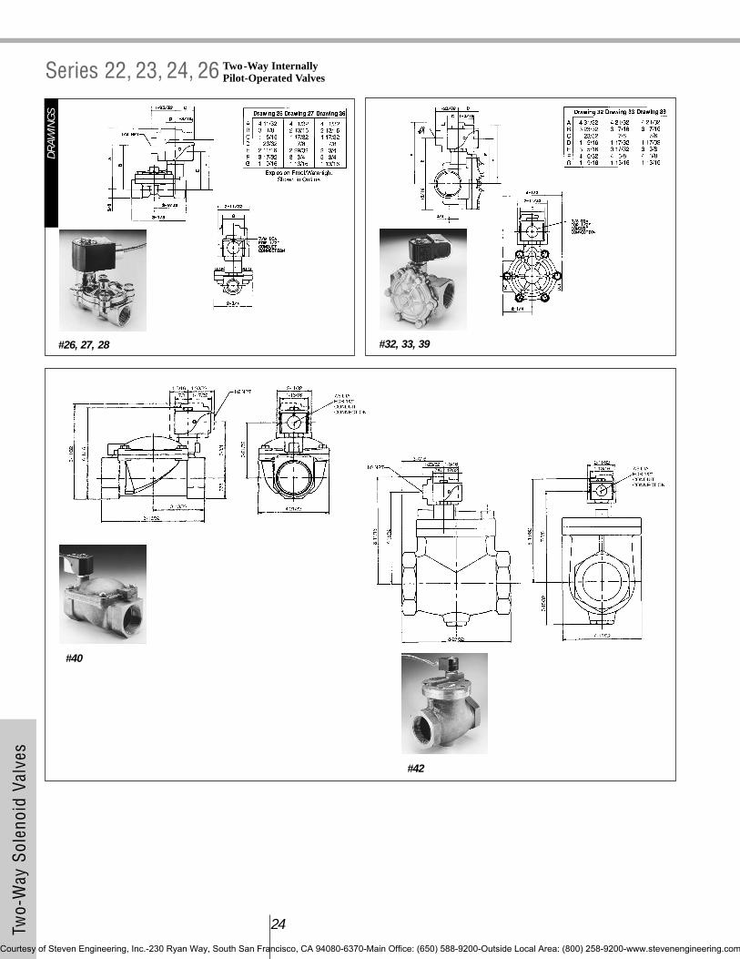
24Two-
Way
Sol
enoi
d Va
lves
Two-Way Internally Pilot-Operated ValvesSeries 22, 23, 24, 26
#26, 27, 28
DR
AWIN
GS
#32, 33, 39
#40
#42
Courtesy of Steven Engineering, Inc.-230 Ryan Way, South San Francisco, CA 94080-6370-Main Office: (650) 588-9200-Outside Local Area: (800) 258-9200-www.stevenengineering.com

Two-
Way
Sol
enoi
d Va
lves
25
To choose a solenoid for your valve, referto the AC or DC chart found on the flapattached to the back cover of this catalog.
MechanicalCharacteristics
Standard Materials of Construction• Body-Brass, 316 Stainless Steel as listed• Seals-NBR • Plunger and Pole Piece-430FR Stainless Steel• Plunger Tube-305 Stainless Steel• Springs-302 Stainless Steel• Shading Coil-Copper (Brass Bodies),
Silver (Stainless Steel Bodies)• Disc Holder (Normally Open Valves)-Ryton• Pilot Seats-Nickel Plated Brass• Wire Screen-Brass or Stainless Steel
Compatible Fluids• Gases, Fluid, Light Oils and other clean flowing
media compatible with brass or stainless steel
Electrical Characteristics
Voltages• DC-12, 24 (other voltages available upon
request)• AC-24/60, 110/120-50/60, 220/240-50/60,
Coil• Class F Standard, Class H Available
Agency Approvals• Standard valves with general purpose or
explosion proof solenoid enclosures are ULListed and CSA Certified. For details, consultfactory.
Miscellaneous
Temperature Ratings (media as listed)• AC Voltages: 180°F max.• DC Voltages: 180°F max.• Ambient: 32-77°F (standard)• For temperature variations, consult the factory.
Installation• Valves should be mounted vertical and upright.
See mounting dimensions (nominal) shown here.
Applications• Used in a variety of applications including:
Automated Systems, Dispensing Systems,Instrumentation, Welding Equipment, FoodProcessing Machinery, Water Treatment Systemsand Laundry Equipment.
SPECIFICATIONS
GOLD RING Series 25, H5 Two-Way InternallyPilot-Operated Valves
BRASS VALVES– NORMALLY CLOSED (ENERGIZE TO OPEN), NBR SEALSAC VALVE SPECIFICATIONS
Orifice Diameter Flow Factor Operating Pressure Differential Max. Temp.NPT Max. (MOPD) ValvePipe Min. Air, Inert Gas Water Light Oil 300SSU AC Const. PartSize inch mm Cv Kv (PSI/Bar) (PSI/BAR) (PSI/Bar) (PSI/BAR) °F °C Watt Ref. Number
1/4 11/32 8.73 1.20 1.03 5 0.34 300 20.69 300 20.69 300 20.69 180 82 6.0 46 04F25C2122CAF3/8 11/32 8.73 1.20 1.03 5 0.34 300 20.69 300 20.69 300 20.69 180 82 6.0 47 06F25C2122CAF1/2 1/2 12.70 3.60 3.10 0 0.00 200 13.79 200 13.79 200 13.79 180 82 11.0 48 08FH5C2132ACF3/4 3/4 19.05 7.40 6.38 0 0.00 200 13.79 200 13.79 200 13.79 180 82 11.0 49 12FH5C2148ACF1 1 25.40 12.2 10.52 1 0.07 300 20.69 300 20.69 300 20.69 180 82 11.0 50 16F25C2164ACF
BRASS VALVES– NORMALLY OPEN (ENERGIZE TO CLOSE), NBR SEALSAC VALVE SPECIFICATIONS
Orifice Diameter Flow Factor Operating Pressure Differential Max. Temp.NPT Max. (MOPD) ValvePipe Min. Air, Inert Gas Water Light Oil 300SSU AC Const. PartSize inch mm Cv Kv (PSI/Bar) (PSI/BAR) (PSI/Bar) (PSI/BAR) °F °C Watt Ref. Number
1/4 11/32 8.73 1.20 1.03 5 0.34 300 20.69 300 20.69 300 20.69 180 82 11.0 51 04F25O2122CCF3/8 11/32 8.73 1.20 1.03 5 0.34 300 20.69 300 20.69 300 20.69 180 82 11.0 52 06F25O2122CCF3/8 1/2 12.70 3.0 2.59 1 0.07 200 13.79 175 12.07 175 12.07 180 82 11.0 53 06F25O2132ACF1/2 1/2 12.70 3.60 3.10 1 0.07 200 13.79 175 12.07 175 12.07 180 82 11.0 53 08F25O2132ACF3/4 3/4 19.05 7.40 6.38 1 0.07 275 18.97 275 18.97 275 18.97 180 82 11.0 54 12F25O2148ACF1 1 25.40 12.2 10.52 1 0.07 300 20.69 250 17.24 230 15.86 180 82 11.0 55 16F25O2164ACF
Courtesy of Steven Engineering, Inc.-230 Ryan Way, South San Francisco, CA 94080-6370-Main Office: (650) 588-9200-Outside Local Area: (800) 258-9200-www.stevenengineering.com
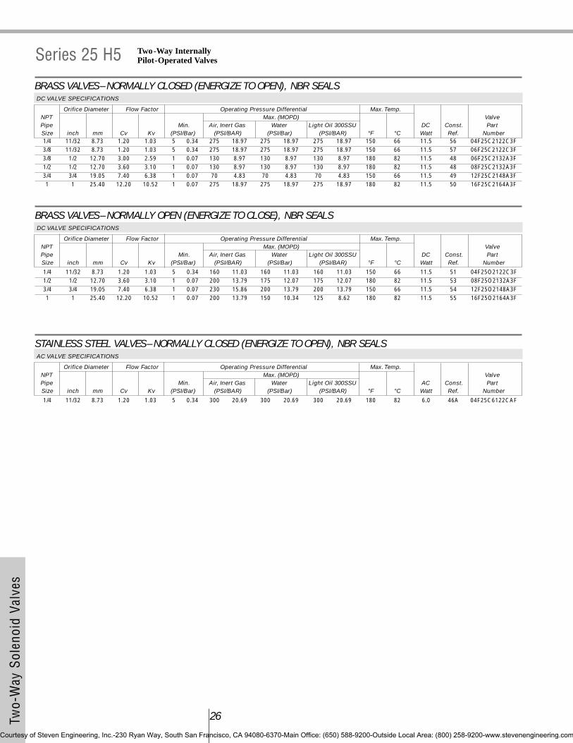
26Two-
Way
Sol
enoi
d Va
lves
BRASS VALVES– NORMALLY CLOSED (ENERGIZE TO OPEN), NBR SEALSDC VALVE SPECIFICATIONS
Orifice Diameter Flow Factor Operating Pressure Differential Max. Temp.NPT Max. (MOPD) ValvePipe Min. Air, Inert Gas Water Light Oil 300SSU DC Const. PartSize inch mm Cv Kv (PSI/Bar) (PSI/BAR) (PSI/Bar) (PSI/BAR) °F °C Watt Ref. Number1/4 11/32 8.73 1.20 1.03 5 0.34 275 18.97 275 18.97 275 18.97 150 66 11.5 56 04F25C2122C3F3/8 11/32 8.73 1.20 1.03 5 0.34 275 18.97 275 18.97 275 18.97 150 66 11.5 57 06F25C2122C3F3/8 1/2 12.70 3.00 2.59 1 0.07 130 8.97 130 8.97 130 8.97 180 82 11.5 48 06F25C2132A3F1/2 1/2 12.70 3.60 3.10 1 0.07 130 8.97 130 8.97 130 8.97 180 82 11.5 48 08F25C2132A3F3/4 3/4 19.05 7.40 6.38 1 0.07 70 4.83 70 4.83 70 4.83 150 66 11.5 49 12F25C2148A3F1 1 25.40 12.20 10.52 1 0.07 275 18.97 275 18.97 275 18.97 180 82 11.5 50 16F25C2164A3F
BRASS VALVES– NORMALLY OPEN (ENERGIZE TO CLOSE), NBR SEALSDC VALVE SPECIFICATIONS
Orifice Diameter Flow Factor Operating Pressure Differential Max. Temp.NPT Max. (MOPD) ValvePipe Min. Air, Inert Gas Water Light Oil 300SSU DC Const. PartSize inch mm Cv Kv (PSI/Bar) (PSI/BAR) (PSI/Bar) (PSI/BAR) °F °C Watt Ref. Number
1/4 11/32 8.73 1.20 1.03 5 0.34 160 11.03 160 11.03 160 11.03 150 66 11.5 51 04F25O2122C3F1/2 1/2 12.70 3.60 3.10 1 0.07 200 13.79 175 12.07 175 12.07 180 82 11.5 53 08F25O2132A3F3/4 3/4 19.05 7.40 6.38 1 0.07 230 15.86 200 13.79 200 13.79 150 66 11.5 54 12F25O2148A3F1 1 25.40 12.20 10.52 1 0.07 200 13.79 150 10.34 125 8.62 180 82 11.5 55 16F25O2164A3F
STAINLESS STEEL VALVES– NORMALLY CLOSED (ENERGIZE TO OPEN), NBR SEALSAC VALVE SPECIFICATIONS
Orifice Diameter Flow Factor Operating Pressure Differential Max. Temp.NPT Max. (MOPD) ValvePipe Min. Air, Inert Gas Water Light Oil 300SSU AC Const. PartSize inch mm Cv Kv (PSI/Bar) (PSI/BAR) (PSI/Bar) (PSI/BAR) °F °C Watt Ref. Number
1/4 11/32 8.73 1.20 1.03 5 0.34 300 20.69 300 20.69 300 20.69 180 82 6.0 46A 04F25C6122CAF
Two-Way InternallyPilot-Operated ValvesSeries 25 H5
Courtesy of Steven Engineering, Inc.-230 Ryan Way, South San Francisco, CA 94080-6370-Main Office: (650) 588-9200-Outside Local Area: (800) 258-9200-www.stevenengineering.com

Two-
Way
Sol
enoi
d Va
lves
27
To choose a solenoid for your valve, referto the AC or DC chart found on the flapattached to the back cover of this catalog.
#46,46A,47,
51, 52,56,57
DR
AWIN
GS
#50, 55
#48, 49, 53, 54
#50A
Courtesy of Steven Engineering, Inc.-230 Ryan Way, South San Francisco, CA 94080-6370-Main Office: (650) 588-9200-Outside Local Area: (800) 258-9200-www.stevenengineering.com

28Two-
Way
Sol
enoi
d Va
lves
BRASS HOT WATER AND STEAM VALVES–NORMALLY CLOSED (ENERGIZE TO OPEN), ETHYLENE PROPYLENE OR PTFE SEALSAC VALVE SPECIFICATIONS
Orifice Diameter Flow Factor Operating Pressure Differential Max. Temp.NPT Max. (MOPD) ValvePipe Min. Steam Hot Water AC Const. PartSize inch mm Cv Kv (PSI/Bar) (PSI/BAR) (PSI/Bar) Notes °F °C Watt Ref. Number
1/4 5/32 3.97 .52 0.45 0 0.00 11 0.76 - - 1 344 173 11.0 56 04FS0C3410ACH3/8 1/2 12.70 3.00 2.59 1 0.07 50 3.45 - - 2,4 300 149 11.0 57 06FS5C2332ACF3/8 1/2 12.70 3.00 2.59 1 0.07 80 5.52 - - 3 320 160 11.0 57 06FS5C2432ACF3/8 1/2 12.70 3.00 2.59 1 0.07 125 8.62 - - 3 353 178 11.0 57 06FS5C2432ACH3/8 5/8 15.88 3.00 2.59 0 0.00 50 3.45 150 10.34 4 300 149 11.0 58 06FS3C2340ACF1/2 1/2 12.70 3.60 3.10 1 0.07 50 3.45 - - 2,4 300 149 11.0 57 08FS5C2332ACF1/2 1/2 12.70 3.60 3.10 1 0.07 80 5.52 - - 3 320 160 11.0 57 08FS5C2432ACF1/2 1/2 12.70 3.60 3.10 1 0.07 125 8.62 - - 3 353 178 11.0 57 08FS5C2432ACH1/2 5/8 15.88 4.00 3.45 0 0.00 50 3.45 150 10.34 4 300 149 11.0 58 08FS3C2340ACF3/4 3/4 19.05 7.40 6.38 1 0.07 50 3.45 - - 2,4 300 149 11.0 59 12FS5C2348ACF3/4 3/4 19.05 7.40 6.38 1 0.07 80 5.52 - - 3 320 160 11.0 59 12FS5C2448ACF3/4 3/4 19.05 7.40 6.38 1 0.07 125 8.62 - - 3 353 178 11.0 59 12FS5C2448ACH3/4 3/4 19.05 5.00 4.31 0 0.00 50 3.45 150 10.34 4 300 149 11.0 60 12FS3C2348ACF1 1 25.40 12.20 10.52 1 0.07 50 3.45 150 10.34 4 300 149 11.0 61 16FS5C2364ACF1 1 25.40 12.20 10.52 1 0.07 80 5.52 - - 3 320 160 11.0 61 16FS5C2464ACF1 1 25.40 12.20 10.52 1 0.07 125 8.62 - - 3 353 178 11.0 61 16FS5C2464ACH
1 1/4 1 1/8 28.58 15.00 12.93 5 0.34 50 3.45 150 10.34 4 300 149 6.0 62 20FS4C2372AAF1 1/2 1 1/2 38.10 22.50 19.40 5 0.34 50 3.45 150 10.34 4 300 149 6.0 63 24FS4C2380AAF
MechanicalCharacteristics
Standard Materials of Construction• Body-Brass, 303 Stainless Steel as listed• Seals-Ethylene Propylene or PTFE and FKM • Plunger and Pole Piece-430FR Stainless Steel• Plunger Tube-305 Stainless Steel• Springs-302 Stainless Steel• Shading Coil-Copper (Brass Bodies), Silver
(Stainless Steel Bodies)• Disc Holder (Normally Open Valves)-
50 psi Steam: Ryton, 125 psi Steam: 303Stainless Steel
• Pilot Seats-Nickel Plated Brass
Compatible Fluids• Ideal for the control of hot water and steam
Electrical Characteristics
Voltages• DC12, 24(other voltages available upon request)• AC-24/60, 110/120-50/60, 220/240-50/60,
440/480-50/60
Coil• Class F Standard, Class H Available
Agency Approvals• Standard valves with general purpose or
explosion proof solenoid enclosures are ULListed and CSA Certified. For details, consult factory.
Miscellaneous
Temperature Ratings (media as listed)• AC Voltages: 353°F max.• DC Voltages: 150°F max.• Ambient: 32-77°F (standard)• For temperature variations consult the factory.
Installation• Valves should be mounted vertical and upright.
See mounting dimensions (nominal) shown here.
Applications• Used in a variety of applications including:
Dry Cleaning, Steam Irons, Steam Baths,Autoclaves, Molding, Steam Atomization,Sterilizers and Laundry Equipment.
• Series S0 Valves are direct acting valves; SeriesS4 and Series S5 are offset or center pilot valves;Series S3 valves are hung diaphragm withintegral seats.
SPECIFICATIONS
GOLD RING Series S, Two-Way Hot Water and Steam Valves
Courtesy of Steven Engineering, Inc.-230 Ryan Way, South San Francisco, CA 94080-6370-Main Office: (650) 588-9200-Outside Local Area: (800) 258-9200-www.stevenengineering.com

Two-
Way
Sol
enoi
d Va
lves
29
To choose a solenoid for your valve, referto the AC or DC chart found on the flapattached to the back cover of this catalog.
BRASS STEAM VALVES–NORMALLY OPEN (ENERGIZE TO CLOSE), ETHYLENE PROPYLENE OR PTFE SEALSAC VALVE SPECIFICATIONS
Orifice Diameter Flow Factor Operating Pressure Differential Max. Temp.NPT Max. (MOPD) ValvePipe Min. Steam Hot Water AC Const. PartSize inch mm Cv Kv (PSI/Bar) (PSI/BAR) (PSI/Bar) Notes °F °C Watt Ref. Number
3/8 1/2 12.70 3.00 2.59 1 0.07 125 8.62 - - 3 353 178 11.0 64 06FS5O2432ACH1/2 1/2 12.70 3.60 3.10 1 0.07 125 8.62 - - 3 353 178 11.0 64 08FS5O2432ACH3/4 3/4 19.05 7.40 6.38 1 0.07 125 8.62 - - 3 353 178 11.0 65 12FS5O2448ACH1 1 25.40 12.20 10.52 1 0.07 125 8.62 - - 3 353 178 11.0 66 16FS5O2464ACH
1 1/2 1 1/2 38.10 22.50 19.40 5 0.34 50 3.45 - - 4 300 149 11.0 67 24FS4O2380ACF
1. Valve contains stainless steel valve body.2. Valve contains stainless steel seat and ethylene propylene elastomers.3. Valve contains stainless steel seat and PTFE elastomers.4. Valves with ethylene propylene elastomers are limited to 50 psi and 300°F (149°C). Do not use on
higher pressure steam with pressure reducing valve, since this may result in super heated steam.
BRASS HOT WATER VALVES–NORMALLY CLOSED (FOR NORMALLY OPEN CONSULT FACTORY), ETHYLENE PROPYLENE SEALSDC VALVE SPECIFICATIONS
Orifice Diameter Flow Factor Operating Pressure Differential Max. Temp.NPT Max. (MOPD) ValvePipe Min. Steam Hot Water DC Const. PartSize inch mm Cv Kv (PSI/Bar) (PSI/BAR) (PSI/Bar) Notes °F °C Watt Ref. Number
3/8 5/8 15.88 3.00 2.59 5 0.34 - - 100 6.90 - 150 66 11.5 58 06F22C2340A3F3/8 5/8 15.88 3.00 2.59 0 0.00 - - 40 2.76 - 150 66 11.5 58 06F23C2340A3F1/2 5/8 15.88 4.00 3.45 5 0.34 - - 100 6.90 - 150 66 11.5 58 08F22C2340A3F1/2 5/8 15.88 4.00 3.45 0 0.00 - - 40 2.76 - 150 66 11.5 58 08F23C2340A3F3/4 3/4 19.05 5.00 4.31 5 0.34 - - 100 6.90 - 150 66 11.5 60 12F22C2348A3F3/4 3/4 19.05 5.00 4.31 0 0.00 - - 40 2.76 - 150 66 11.5 60 12F23C2348A3F
#61, 66
DR
AWIN
GS
#57, 59, 64, 65
Courtesy of Steven Engineering, Inc.-230 Ryan Way, South San Francisco, CA 94080-6370-Main Office: (650) 588-9200-Outside Local Area: (800) 258-9200-www.stevenengineering.com

30Two-
Way
Sol
enoi
d Va
lves
Series S, Two-Way Hot Water and Steam Valves
#62
DR
AWIN
GS
#56 #63, 67
#58, 60
Courtesy of Steven Engineering, Inc.-230 Ryan Way, South San Francisco, CA 94080-6370-Main Office: (650) 588-9200-Outside Local Area: (800) 258-9200-www.stevenengineering.com

Two-
Way
Sol
enoi
d Va
lves
31
To choose a solenoid for your valve, referto the AC or DC chart found on the flapattached to the back cover of this catalog.
MechanicalCharacteristics
Standard Materials of Construction• Body-Brass• Seals-NBR and Urethane• Plunger and Pole Piece-430FR Stainless Steel• Plunger Tube-305 Stainless Steel• Springs-302 Stainless Steel• Shading Coil-Copper (Brass Bodies)• Piston-Delrin• Piston Rings-Teflon
Compatible Fluids• Generally installed where high pressure and
large flow requirements dictate the use of piston valves
Electrical Characteristics
Voltages• DC-12, 24 (other voltages available upon
request)• AC-24/60, 110/120-50/60, 220/240-50/60,
Coil• Class F Standard, Class H Available
Miscellaneous
Temperature Ratings (media as listed)• AC Voltages: 200°F max.• DC Voltages: 150°F max.• Ambient: 32-77°F (standard)• For temperature variations, consult the factory.
Installation• Valves should be mounted vertical and upright.
See mounting dimensions (nominal) shown here.For certified dimensions, consult factory.
Applications• Used in a variety of applications including: Blow
Molding, Compressors, Car Washer Equipment,and Pumps.
SPECIFICATIONS
GOLD RING Series 28 Two-Way Internally Pilot-OperatedHigh Pressure Valves
HIGH PRESSURE BRASS VALVES– NORMALLY CLOSED (ENERGIZE TO OPEN), NBR SEALSAC VALVE SPECIFICATIONS
Orifice Diameter Flow Factor Operating Pressure Differential Max. Temp.NPT Max. (MOPD) ValvePipe Min. Air, Inert Gas Water Light Oil 300SSU AC Const. PartSize inch mm Cv Kv (PSI/Bar) (PSI/BAR) (PSI/Bar) (PSI/BAR) °F °C Watt Ref. Number
1/4 5/16 7.94 1.5 1.29 15 1.03 1500 103.45 1500 103.45 1500 103.45 200 93 11.0 69A 04F28C1D20ACF3/8 5/16 7.94 1.5 1.29 15 1.03 1500 103.45 1500 103.45 1500 103.45 200 93 11.0 69B 06F28C1D20ACF1/2 3/8 9.53 3.2 2.76 25 1.72 1500 103.45 1500 103.45 1500 103.45 200 93 11.0 69 08F28C1D24ACF3/4 3/4 19.05 7.8 6.72 25 1.72 1000 68.97 1000 68.97 1000 68.97 200 93 11.0 70 12F28C1D48BCF
HIGH PRESSURE BRASS VALVES– NORMALLY OPEN (ENERGIZE TO CLOSE), NBR SEALSAC VALVE SPECIFICATIONS
Orifice Diameter Flow Factor Operating Pressure Differential Max. Temp.NPT Max. (MOPD) ValvePipe Min. Air, Inert Gas Water Light Oil 300SSU AC Const. PartSize inch mm Cv Kv (PSI/Bar) (PSI/BAR) (PSI/Bar) (PSI/BAR) °F °C Watt Ref. Number
1/2 3/8 9.53 3.2 2.76 25 1.72 1000 68.97 1000 68.97 1000 68.97 200 93 11.0 71 08F28O1D28ACF3/4 3/4 19.05 7.8 6.72 25 1.72 500 34.48 500 34.48 500 34.48 200 93 11.0 72 12F28O1D48BCF
HIGH PRESSURE BRASS VALVES– NORMALLY CLOSED (ENERGIZE TO OPEN), NBR SEALSDC VALVE SPECIFICATIONS
Orifice Diameter Flow Factor Operating Pressure Differential Max. Temp.NPT Max. (MOPD) ValvePipe Min. Air, Inert Gas Water Light Oil 300SSU DC Const. PartSize inch mm Cv Kv (PSI/Bar) (PSI/BAR) (PSI/Bar) (PSI/BAR) °F °C Watt Ref. Number
1/2 3/8 9.53 3.2 2.76 25 1.72 500 34.48 500 34.48 500 34.48 150 66 11.5 69 08F28C1D24A3F3/4 3/4 19.05 7.8 6.72 25 1.72 450 31.03 450 31.03 450 31.03 150 66 11.5 70 12F28C1D48A3F
Courtesy of Steven Engineering, Inc.-230 Ryan Way, South San Francisco, CA 94080-6370-Main Office: (650) 588-9200-Outside Local Area: (800) 258-9200-www.stevenengineering.com

32Two-
Way
Sol
enoi
d Va
lves
To choose a solenoid for your valve, referto the AC or DC chart found on the flapattached to the back cover of this catalog.
#69, 69A, 69B, 70, 71, 72
DR
AWIN
GS
Explosion-Proof/WatertightShown in Outline
Series 28 Two-Way Internally Pilot-OperatedHigh Pressure Valves
Courtesy of Steven Engineering, Inc.-230 Ryan Way, South San Francisco, CA 94080-6370-Main Office: (650) 588-9200-Outside Local Area: (800) 258-9200-www.stevenengineering.com

Three-Way Valve Contents
Gold Ring Three-Way Valve Specifications ...... 33-42
Series 30, Direct Acting .................................. 34-37Series 34, Pilot Operated ................................ 38-39Series 35, 38 Quick Exhaust .......................... 40-42
Courtesy of Steven Engineering, Inc.-230 Ryan Way, South San Francisco, CA 94080-6370-Main Office: (650) 588-9200-Outside Local Area: (800) 258-9200-www.stevenengineering.com

DIRECT ACTING BRASS VALVES– NORMALLY CLOSED (PRESSURE AT 2, ENERGIZE TO OPEN), NBR SEALSAC VALVE SPECIFICATIONS
Orifice Diameter Flow Factor Operating Pressure Differential Max. Temp.NPT Max. (MOPD) ValvePipe Min. Air, Inert Gas Water Light Oil 300SSU AC Const. PartSize inch mm Cv Kv (PSI/Bar) (PSI/BAR) (PSI/Bar) (PSI/BAR) °F °C Watt Ref. Number
1/8 3/64 1.19 .06 0.05 0 200 13.79 200 13.79 200 13.79 180 82 6.0 73 02F30C1103AAF1/8 1/16 1.59 .09 0.08 0 125 8.62 125 8.62 125 8.62 180 82 6.0 73 02F30C1104AAF1/8 3/32 2.38 .12 0.10 0 100 6.90 100 6.90 100 6.90 180 82 6.0 73 02F30C1106AAF1/8 1/8 3.18 .21 0.18 0 40 2.76 40 2.76 40 2.76 180 82 6.0 73 02F30C1108AAF1/4 1/16 1.59 .0 0.08 0 125 8.62 125 8.62 125 8.62 180 82 6.0 74 04F30C2104AAF1/4 3/32 2.38 .12 0.10 0 150 10.34 150 10.34 150 10.34 200 93 11.0 75 04F30C2106ACF1/4 1/8 3.18 .25 0.22 0 85 2.76 85 2.76 85 2.76 180 82 6.0 74 04F30C2108ACF1/4 11/64 4.37 .35 0.30 0 45 2.07 45 2.07 45 2.07 180 82 10.2 74 04F30C2111ACF
MechanicalCharacteristics
Standard Materials of Construction• Body-Brass or 303 Stainless Steel as listed• Seals-NBR • Plunger and Pole Piece-430FR Stainless Steel• Plunger Tube-305 Stainless Steel• Springs-302 Stainless Steel• Shading Coil-Copper (Brass Bodies),
Silver (Stainless Steel Bodies)• Disc Holder-Celcon
Electrical Characteristics
Voltages• DC-12, 24 (other voltages available upon
request)• AC-24/60, 110/120-50/60, 220/240-50/60,
Coil• Class F Standard, Class H Available
Agency Approvals• Standard valves with general purpose or
explosion proof solenoid enclosures are ULListed and CSA Certified.
Miscellaneous
Temperature Ratings (media as listed)• AC Voltages: 200°F max.• DC Voltages: 150°F max.• Ambient: 32-77°F (standard)• For temperature variations, consult the factory.
Installation• Series 30 valves may be mounted in any
position. Product and mounting dimensionsshown are nominal. For certified dimensions,consult factory.
Applications• Used in a variety of applications including:
Automated Systems, Dispensing Systems,Instrumentation, Pilot Operators, LaundryEquipment, Sampling Systems, Compressors,Water Treatment, and Air Dryers.
Operating Specifications• Normally Closed-energize to pressurize
operating device. De-energized, operating deviceis exhausted.
• Normally Open-energize to exhaust operatingdevice. De-energized, operating device ispressurized.
• Universal-Can be installed for either normallyclosed, or normally open operation. Universalmode of operation is also suitable for flowselection (pressure at port 2 and 3) or diversion(pressure at port 1).
SPECIFICATIONS
GOLD RING Series 30 Small Three-WayDirect Acting Valves
DIRECT ACTING BRASS VALVES– NORMALLY OPEN (PRESSURE AT 3, ENERGIZE TO CLOSE), NBR SEALSAC VALVE SPECIFICATIONS
Orifice Diameter Flow Factor Operating Pressure Differential Max. Temp.NPT Max. (MOPD) ValvePipe Min. Air, Inert Gas Water Light Oil 300SSU AC Const. PartSize inch mm Cv Kv (PSI/Bar) (PSI/BAR) (PSI/Bar) (PSI/BAR) °F °C Watt Ref. Number
1/8 3/64 1.19 .06 0.05 0 200 13.79 200 13.79 200 13.79 180 82 6.0 73 02F30O1103AAF1/8 1/16 1.59 .09 0.08 0 125 8.62 125 8.62 125 8.62 180 82 6.0 73 02F30O1104AAF1/8 3/32 2.38 .12 0.10 0 100 6.90 100 6.90 100 6.90 180 82 6.0 73 02F30O1106AAF1/8 1/8 3.18 .21 0.18 0 40 2.76 40 2.76 40 2.76 180 82 6.0 73 02F30O1108AAF1/4 1/16 1.59 .09 0.08 0 235 16.21 250 17.24 250 17.24 200 93 16.0 75 04F30O2104ADF1/4 3/32 2.38 .12 0.10 0 140 9.66 140 9.66 140 9.66 200 93 11.0 75 04F30O2106ACF1/4 1/8 3.18 .25 0.22 0 70 4.83 70 4.83 70 4.83 200 93 11.0 75 04F30O2108ACF1/4 11/64 4.37 .35 0.30 0 40 2.76 40 2.76 40 2.76 200 93 11.0 75 04F30O2111ACF
Thre
e-W
ay S
olen
oid
Valv
es
34
Courtesy of Steven Engineering, Inc.-230 Ryan Way, South San Francisco, CA 94080-6370-Main Office: (650) 588-9200-Outside Local Area: (800) 258-9200-www.stevenengineering.com

To choose a solenoid for your valve, referto the AC or DC chart found on the flapattached to the back cover of this catalog.
35
Thre
e-W
ay S
olen
oid
Valv
es
DIRECT ACTING BRASS VALVES– UNIVERSAL (PRESSURE AT ANY PORT), NBR SEALSAC VALVE SPECIFICATIONS
Orifice Diameter Flow Factor Operating Pressure Differential Max. Temp.NPT Max. (MOPD) ValvePipe Min. Air, Inert Gas Water Light Oil 300SSU AC Const. PartSize inch mm Cv Kv (PSI/Bar) (PSI/BAR) (PSI/Bar) (PSI/BAR) °F °C Watt Ref. Number
1/8 3/64 1.19 .06 0.05 0 175 12.07 175 12.07 175 12.07 140 60 10.2 73 02F30U1103ABF1/8 1/16 1.59 .09 0.08 0 100 6.90 100 6.90 100 6.90 180 82 10.2 73 02F30U1104ABF1/8 3/32 2.38 .12 0.10 0 50 3.45 50 3.45 50 3.45 180 82 6.0 73 02F30U1106AAF1/8 1/8 3.18 .21 0.18 0 30 2.07 30 2.07 30 2.07 180 82 10.2 73 02F30U1108ABF1/4 1/16 1.59 .09 0.08 0 125 8.62 130 8.97 130 8.97 200 93 11.0 75 04F30U2104ACF1/4 3/32 2.38 .12 0.10 0 100 6.90 100 6.90 100 6.90 200 93 16.0 75 04F30U2106ADF1/4 1/8 3.18 .25 0.22 0 50 3.45 50 3.45 50 3.45 200 93 16.0 75 04F30U2108ADF1/4 11/64 4.37 .35 0.30 0 20 1.38 20 1.38 20 1.38 200 93 11.0 75 04F30U2111ACF
DIRECT ACTING BRASS VALVES– NORMALLY CLOSED (PRESSURE AT 2, ENERGIZE TO OPEN), NBR SEALSDC VALVE SPECIFICATIONS
Orifice Diameter Flow Factor Operating Pressure Differential Max. Temp.NPT Max. (MOPD) ValvePipe Min. Air, Inert Gas Water Light Oil 300SSU DC Const. PartSize inch mm Cv Kv (PSI/Bar) (PSI/BAR) (PSI/Bar) (PSI/BAR) °F °C Watt Ref. Number
1/8 3/64 1.19 .06 0.05 0 200 13.79 200 13.79 200 13.79 120 49 9.5 73 02F30C1103A1F1/8 1/16 1.59 .09 0.08 0 125 8.62 125 8.62 125 8.62 120 49 9.5 73 02F30C1104A1F1/8 3/32 2.38 .12 0.10 0 100 6.90 100 6.90 100 6.90 120 49 9.5 73 02F30C1106A1F1/8 1/8 3.18 .21 0.18 0 40 2.76 40 2.76 40 2.76 120 49 9.5 73 02F30C1108A1F1/4 1/16 1.59 .09 0.08 0 160 11.03 160 11.03 160 11.03 150 66 11.5 75 04F30C2104A3F1/4 3/32 2.38 12 10.34 0 115 7.93 115 7.93 115 7.93 150 66 11.5 75 04F30C2106A3F1/4 1/8 3.18 .25 0.22 0 60 4.14 60 4.14 60 4.14 150 66 11.5 75 04F30C2108A3F1/4 11/64 4.37 .35 0.30 0 25 1.72 25 1.72 25 1.72 150 66 11.5 75 04F30C2111A3F
DIRECT ACTING BRASS VALVES– NORMALLY OPEN (PRESSURE AT 3, ENERGIZE TO CLOSE), NBR SEALSDC VALVE SPECIFICATIONS
Orifice Diameter Flow Factor Operating Pressure Differential Max. Temp.NPT Max. (MOPD) ValvePipe Min. Air, Inert Gas Water Light Oil 300SSU DC Const. PartSize inch mm Cv Kv (PSI/Bar) (PSI/BAR) (PSI/Bar) (PSI/BAR) °F °C Watt Ref. Number
1/8 3/64 1.19 .06 0.05 0 200 13.79 200 13.79 200 13.79 120 49 9.5 73 02F30O1103A1F1/8 1/16 1.59 .09 0.08 0 200 13.79 200 13.79 200 13.79 120 49 9.5 73 02F30O1104A1F1/8 3/32 2.38 .12 0.10 0 100 6.90 100 6.90 100 6.90 120 49 9.5 73 02F30O1106A1F1/8 1/8 3.18 .21 0.18 0 40 2.76 40 2.76 40 2.76 120 49 9.5 73 02F30O1108A1F1/4 1/16 1.59 .09 0.08 0 160 11.03 160 11.03 160 11.03 150 66 11.5 75 04F30O2140A3F1/4 3/32 2.38 .12 0.10 0 100 6.90 100 6.90 100 6.90 150 66 11.5 75 04F30O2106A3F1/4 1/8 3.18 .12 0.10 0 55 3.79 55 3.79 55 3.79 150 66 11.5 75 04F30O2108A3F1/4 11/64 4.37 .35 0.30 0 30 2.07 30 2.07 30 2.07 150 66 11.5 75 04F30O2111A3F
DIRECT ACTING BRASS VALVES– UNIVERSAL (PRESSURE AT ANY PORT), NBR SEALSDC VALVE SPECIFICATIONS
Orifice Diameter Flow Factor Operating Pressure Differential Max. Temp.NPT Max. (MOPD) ValvePipe Min. Air, Inert Gas Water Light Oil 300SSU DC Const. PartSize inch mm Cv Kv (PSI/Bar) (PSI/BAR) (PSI/Bar) (PSI/BAR) °F °C Watt Ref. Number
1/8 3/64 1.19 .06 0.05 0 125 8.62 125 8.62 125 8.62 120 49 9.5 73 02F30U1103A1F1/8 1/16 1.59 .09 0.08 0 65 4.48 65 4.48 65 4.48 120 49 9.5 73 02F30U1104A1F1/8 3/32 2.38 .12 0.10 0 50 3.45 50 3.45 50 3.45 120 49 9.5 73 02F30U1106A1F1/8 1/8 3.18 .21 0.18 0 20 1.38 20 1.38 20 1.38 120 49 9.5 73 02F30U1108A1F1/4 1/16 1.59 .09 0.08 0 75 5.17 75 5.17 75 5.17 150 66 11.5 75 04F30U2104A3F1/4 3/32 2.38 .12 0.10 0 60 4.14 60 4.14 60 4.14 150 66 11.5 75 04F30U2106A3F1/4 1/8 3.18 .25 0.22 0 25 1.72 25 1.72 25 1.72 150 66 11.5 75 04F30U2108A3F1/4 11/64 4.37 .35 0.30 0 12 0.83 12 0.83 12 0.83 150 66 11.5 75 04F30U2111A3F
Courtesy of Steven Engineering, Inc.-230 Ryan Way, South San Francisco, CA 94080-6370-Main Office: (650) 588-9200-Outside Local Area: (800) 258-9200-www.stevenengineering.com

Thre
e-W
ay S
olen
oid
Valv
es
Small Three-Way Direct Acting ValvesSeries 30
DIRECT ACTING STAINLESS STEEL VALVES–NORMALLY CLOSED (PRESSURE AT 2, ENERGIZE TO OPEN), NBR SEALSAC VALVE SPECIFICATIONS
Orifice Diameter Flow Factor Operating Pressure Differential Max. Temp.NPT Max. (MOPD) ValvePipe Min. Air, Inert Gas Water Light Oil 300SSU AC Const. PartSize inch mm Cv Kv (PSI/Bar) (PSI/BAR) (PSI/Bar) (PSI/BAR) °F °C Watt Ref. Number
1/8 3/64 1.19 .06 0.05 0 200 13.79 200 13.79 200 13.79 180 82 6.0 73 02F30C3103AAF1/8 1/16 1.59 .09 0.08 0 125 8.62 125 8.62 125 8.62 180 82 6.0 73 02F30C3104AAF1/8 3/32 2.38 .12 0.10 0 100 6.90 100 6.90 100 6.90 180 82 6.0 73 02F30C3106AAF1/8 1/8 3.18 .21 0.18 0 40 2.76 40 2.76 40 2.76 180 82 6.0 73 02F30C3108AAF1/4 1/16 1.59 .09 0.08 0 125 8.62 125 8.62 125 8.62 180 82 6.0 76 04F30C3104AAF1/4 3/32 2.38 .12 0.10 0 150 10.34 150 10.34 150 10.34 200 93 11.0 76 04F30C3106ACF1/4 1/8 3.18 .31 0.27 0 85 5.86 85 5.86 85 5.86 200 93 11.0 76 04F30C3108ACF
DIRECT ACTING STAINLESS STEEL VALVES– UNIVERSAL (PRESSURE AT ANY PORT), NBR SEALSAC VALVE SPECIFICATIONS
Orifice Diameter Flow Factor Operating Pressure Differential Max. Temp.NPT Max. (MOPD) ValvePipe Min. Air, Inert Gas Water Light Oil 300SSU AC Const. PartSize inch mm Cv Kv (PSI/Bar) (PSI/BAR) (PSI/Bar) (PSI/BAR) °F °C Watt Ref. Number
1/8 3/64 1.19 .06 0.05 0 175 12.07 175 12.07 175 12.07 140 60 10.2 73 02F30U3103ABF1/8 1/16 1.59 .09 0.08 0 100 6.90 100 6.90 100 6.90 180 82 10.2 73 02F30U3104ABF1/8 3/32 2.38 .12 0.10 0 50 3.45 50 3.45 50 3.45 180 82 6.0 73 02F30U3106AAF1/8 1/8 3.18 .21 0.18 0 30 2.07 30 2.07 30 2.07 180 82 10.2 73 02F30U3108ABF1/4 3/32 2.38 12 10.34 0 100 6.90 100 6.90 100 6.90 200 93 16.0 76A 04F30U3106ADF1/4 1/8 3.18 .31 0.27 0 50 3.45 50 3.45 50 3.45 200 93 16.0 76A 04F30U3108ADF
DIRECT ACTING STAINLESS STEEL VALVES–NORMALLY OPEN (PRESSURE AT 3, ENERGIZE TO CLOSE), NBR SEALSAC VALVE SPECIFICATIONS
Orifice Diameter Flow Factor Operating Pressure Differential Max. Temp.NPT Max. (MOPD) ValvePipe Min. Air, Inert Gas Water Light Oil 300SSU AC Const. PartSize inch mm Cv Kv (PSI/Bar) (PSI/BAR) (PSI/Bar) (PSI/BAR) °F °C Watt Ref. Number
1/8 3/64 1.19 .06 0.05 0 200 13.79 200 13.79 200 13.79 180 82 6.0 73 02F30O3103AAF1/8 1/16 1.59 .09 0.08 0 125 8.62 125 8.62 125 8.62 180 82 6.0 73 02F30O3104AAF1/8 3/32 2.38 .12 0.10 0 100 6.90 100 6.90 100 6.90 180 82 6.0 73 02F30O3106AAF1/8 1/8 3.18 .21 0.18 0 40 2.76 40 2.76 40 2.76 180 82 6.0 73 02F30O3108AAF1/4 3/32 2.38 .12 0.10 0 150 10.34 140 9.66 140 9.66 200 93 11.0 76A 04F30O3106ACF1/4 1/8 3.18 .31 0.27 0 70 4.83 70 4.83 70 4.83 200 93 11.0 76A 04F30O3108ACF
DIRECT ACTING STAINLESS STEEL VALVES–NORMALLY CLOSED (PRESSURE AT 2, ENERGIZE TO OPEN), NBR SEALSDC VALVE SPECIFICATIONS
Orifice Diameter Flow Factor Operating Pressure Differential Max. Temp.NPT Max. (MOPD) ValvePipe Min. Air, Inert Gas Water Light Oil 300SSU DC Const. PartSize inch mm Cv Kv (PSI/Bar) (PSI/BAR) (PSI/Bar) (PSI/BAR) °F °C Watt Ref. Number
1/8 3/64 1.19 .06 0.05 0 200 13.79 200 13.79 200 13.79 120 49 9.5 73 02F30C3103A1F1/8 1/16 1.59 .09 0.08 0 125 8.62 125 8.62 125 8.62 120 49 9.5 73 02F30C3104A1F1/8 3/32 2.38 .12 0.10 0 100 6.90 100 6.90 100 6.90 120 49 9.5 73 02F30C3106A1F1/8 1/8 3.18 .21 0.18 0 40 2.76 40 2.76 40 2.76 120 49 9.5 73 02F30C3108A1F1/4 3/32 2.38 .12 0.10 0 115 7.93 115 7.93 115 7.93 150 66 11.5 76A 04F30C3106A3F1/4 1/8 3.18 .31 0.27 0 60 4.14 60 4.14 60 4.14 150 66 11.5 76A 04F30C3108A3F
36
Courtesy of Steven Engineering, Inc.-230 Ryan Way, South San Francisco, CA 94080-6370-Main Office: (650) 588-9200-Outside Local Area: (800) 258-9200-www.stevenengineering.com

37
Thre
e-W
ay S
olen
oid
Valv
es
To choose a solenoid for your valve, referto the AC or DC chart found on the flapattached to the back cover of this catalog.
DIRECT ACTING STAINLESS STEEL VALVES–NORMALLY OPEN (PRESSURE AT 3, ENERGIZE TO CLOSE), NBR SEALSDC VALVE SPECIFICATIONS
Orifice Diameter Flow Factor Operating Pressure Differential Max. Temp.NPT Max. (MOPD) ValvePipe Min. Air, Inert Gas Water Light Oil 300SSU DC Const. PartSize inch mm Cv Kv (PSI/Bar) (PSI/BAR) (PSI/Bar) (PSI/BAR) °F °C Watt Ref. Number
1/8 3/64 1.19 .06 0.05 0 200 13.79 200 13.79 200 13.79 120 49 9.5 73 02F30O3103A1F1/8 1/16 1.59 .09 0.08 0 125 8.62 125 8.62 125 8.62 120 49 9.5 73 02F30O3104A1F1/8 3/32 2.38 .12 0.10 0 100 6.90 100 6.90 100 6.90 120 49 9.5 73 02F30O3106A1F1/8 1/8 3.18 .21 0.18 0 40 2.76 40 2.76 40 2.76 120 49 9.5 73 02F30O3108A1F1/4 3/32 2.38 .12 0.10 0 100 6.90 100 6.90 100 6.90 150 66 11.5 76A 04F30O3106A3F1/4 1/8 3.18 .31 0.27 0 55 3.79 55 3.79 55 3.79 150 66 11.5 76A 04F30O3108A3F
DIRECT ACTING STAINLESS STEEL VALVES– UNIVERSAL (PRESSURE AT ANY PORT), NBR SEALSDC VALVE SPECIFICATIONS
Orifice Diameter Flow Factor Operating Pressure Differential Max. Temp.NPT Max. (MOPD) ValvePipe Min. Air, Inert Gas Water Light Oil 300SSU DC Const. PartSize inch mm Cv Kv (PSI/Bar) (PSI/BAR) (PSI/Bar) (PSI/BAR) °F °C Watt Ref. Number
1/8 3/64 1.19 .06 0.05 0 125 8.62 125 8.62 125 8.62 120 49 9.5 73 02F30U3103A1F1/8 1/16 1.59 .09 0.08 0 65 4.48 65 4.48 65 4.48 120 49 9.5 73 02F30U3104A1F1/8 3/32 2.38 .12 0.10 0 50 3.45 50 3.45 50 3.45 120 49 9.5 73 02F30U3106A1F1/8 1/8 3.18 .21 0.18 0 20 1.38 20 1.38 20 1.38 120 49 9.5 73 02F30U3108A1F1/4 3/32 2.38 .12 0.10 0 60 4.14 60 4.14 60 4.14 150 66 11.5 76A 04F30U3106A3F1/4 1/8 3.18 .31 0.27 0 25 1.72 25 1.72 25 1.72 150 66 11.5 76A 04F30U3108A3F
#74, 75#73, 76, 76A
DR
AWIN
GS
Courtesy of Steven Engineering, Inc.-230 Ryan Way, South San Francisco, CA 94080-6370-Main Office: (650) 588-9200-Outside Local Area: (800) 258-9200-www.stevenengineering.com
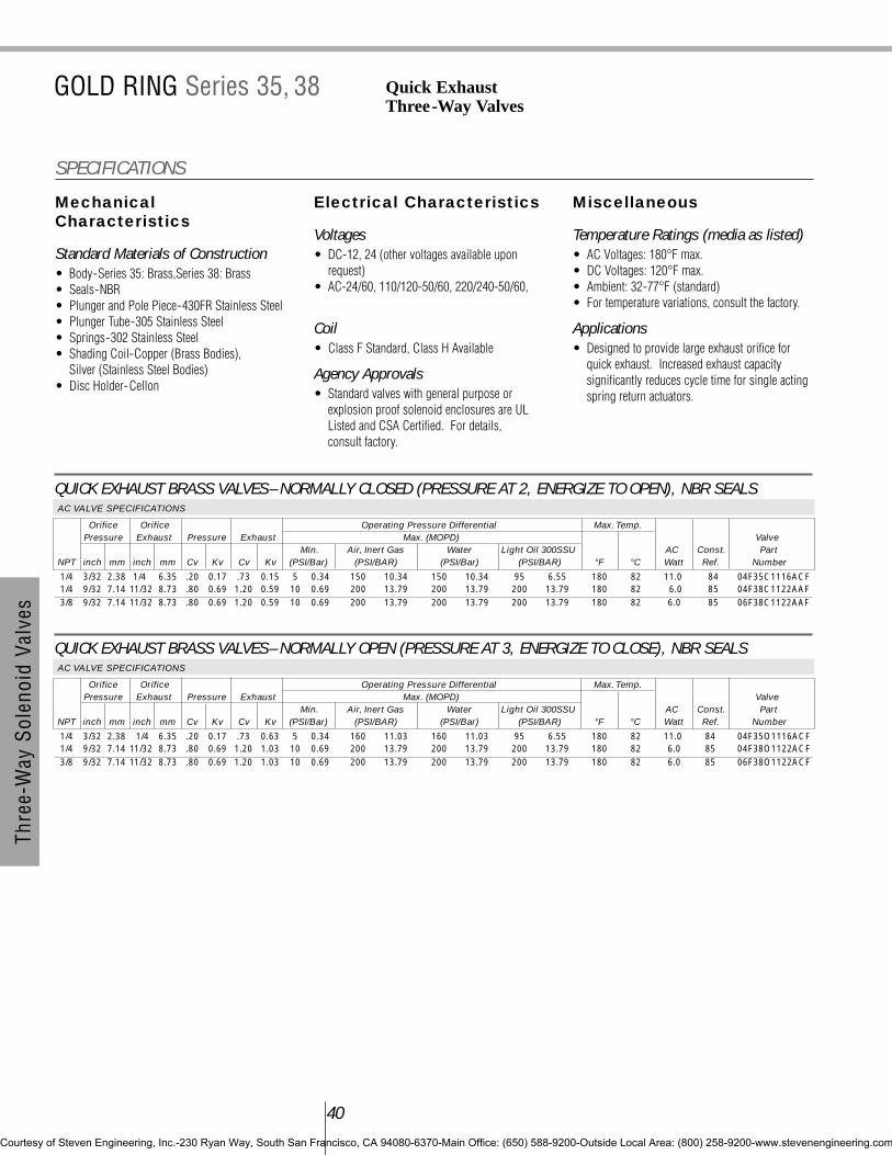
40
Thre
e-W
ay S
olen
oid
Valv
es
QUICK EXHAUST BRASS VALVES– NORMALLY CLOSED (PRESSURE AT 2, ENERGIZE TO OPEN), NBR SEALSAC VALVE SPECIFICATIONS
Orifice Orifice Operating Pressure Differential Max. Temp.Pressure Exhaust Pressure Exhaust Max. (MOPD) Valve
Min. Air, Inert Gas Water Light Oil 300SSU AC Const. PartNPT inch mm inch mm Cv Kv Cv Kv (PSI/Bar) (PSI/BAR) (PSI/Bar) (PSI/BAR) °F °C Watt Ref. Number
1/4 3/32 2.38 1/4 6.35 .20 0.17 .73 0.15 5 0.34 150 10.34 150 10.34 95 6.55 180 82 11.0 84 04F35C1116ACF1/4 9/32 7.14 11/32 8.73 .80 0.69 1.20 0.59 10 0.69 200 13.79 200 13.79 200 13.79 180 82 6.0 85 04F38C1122AAF3/8 9/32 7.14 11/32 8.73 .80 0.69 1.20 0.59 10 0.69 200 13.79 200 13.79 200 13.79 180 82 6.0 85 06F38C1122AAF
QUICK EXHAUST BRASS VALVES– NORMALLY OPEN (PRESSURE AT 3, ENERGIZE TO CLOSE), NBR SEALSAC VALVE SPECIFICATIONS
Orifice Orifice Operating Pressure Differential Max. Temp.Pressure Exhaust Pressure Exhaust Max. (MOPD) Valve
Min. Air, Inert Gas Water Light Oil 300SSU AC Const. PartNPT inch mm inch mm Cv Kv Cv Kv (PSI/Bar) (PSI/BAR) (PSI/Bar) (PSI/BAR) °F °C Watt Ref. Number
1/4 3/32 2.38 1/4 6.35 .20 0.17 .73 0.63 5 0.34 160 11.03 160 11.03 95 6.55 180 82 11.0 84 04F35O1116ACF1/4 9/32 7.14 11/32 8.73 .80 0.69 1.20 1.03 10 0.69 200 13.79 200 13.79 200 13.79 180 82 6.0 85 04F38O1122ACF3/8 9/32 7.14 11/32 8.73 .80 0.69 1.20 1.03 10 0.69 200 13.79 200 13.79 200 13.79 180 82 6.0 85 06F38O1122ACF
MechanicalCharacteristics
Standard Materials of Construction• Body-Series 35: Brass,Series 38: Brass • Seals-NBR• Plunger and Pole Piece-430FR Stainless Steel• Plunger Tube-305 Stainless Steel• Springs-302 Stainless Steel• Shading Coil-Copper (Brass Bodies),
Silver (Stainless Steel Bodies)• Disc Holder-Cellon
Electrical Characteristics
Voltages• DC-12, 24 (other voltages available upon
request)• AC-24/60, 110/120-50/60, 220/240-50/60,
Coil• Class F Standard, Class H Available
Agency Approvals• Standard valves with general purpose or
explosion proof solenoid enclosures are ULListed and CSA Certified. For details, consult factory.
Miscellaneous
Temperature Ratings (media as listed)• AC Voltages: 180°F max.• DC Voltages: 120°F max.• Ambient: 32-77°F (standard)• For temperature variations, consult the factory.
Applications• Designed to provide large exhaust orifice for
quick exhaust. Increased exhaust capacitysignificantly reduces cycle time for single actingspring return actuators.
SPECIFICATIONS
GOLD RING Series 35, 38 Quick Exhaust Three-Way Valves
Courtesy of Steven Engineering, Inc.-230 Ryan Way, South San Francisco, CA 94080-6370-Main Office: (650) 588-9200-Outside Local Area: (800) 258-9200-www.stevenengineering.com

QUICK EXHAUST BRASS VALVES– NORMALLY CLOSED (PRESSURE AT 2, ENERGIZE TO OPEN), NBR SEALSDC VALVE SPECIFICATIONS
Orifice Orifice Operating Pressure Differential Max. Temp.Pressure Exhaust Pressure Exhaust Max. (MOPD) Valve
Min. Air, Inert Gas Water Light Oil 300SSU DC Const. PartNPT inch mm inch mm Cv Kv Cv Kv (PSI/Bar) (PSI/BAR) (PSI/Bar) (PSI/BAR) °F °C Watt Ref. Number
1/4 3/32 2.38 1/4 6.35 .20 0.17 .73 0.63 5 0.34 115 7.93 115 7.93 60 4.14 104 40 11.5 84 04F35C1116A3F1/4 9/32 7.14 11/32 8.73 .80 0.69 1.20 1.03 10 0.69 200 13.79 200 13.79 200 13.79 120 49 11.5 85 04F38C1122A3F3/8 9/32 7.14 11/32 8.73 .80 0.69 1.20 1.03 10 0.69 200 13.79 200 13.79 200 13.79 120 49 11.5 85 06F38C1122A1F
QUICK EXHAUST BRASS VALVES– NORMALLY OPEN (PRESSURE AT 3, ENERGIZE TO CLOSE), NBR SEALSDC VALVE SPECIFICATIONS
Orifice Orifice Operating Pressure Differential Max. Temp.Pressure Exhaust Pressure Exhaust Max. (MOPD) Valve
Min. Air, Inert Gas Water Light Oil 300SSU DC Const. PartNPT inch mm inch mm Cv Kv Cv Kv (PSI/Bar) (PSI/BAR) (PSI/Bar) (PSI/BAR) °F °C Watt Ref. Number
1/4 3/32 2.38 1/4 6.35 .20 0.17 .73 0.63 5 0.34 100 6.90 100 6.90 50 3.45 104 40 11.5 84 04F35O1116A3F1/4 9/32 7.14 11/32 8.73 .80 0.69 1.20 1.03 10 0.69 200 13.79 200 13.79 200 13.79 120 49 11.5 85 04F38O1122A3F3/8 9/32 7.14 11/32 8.73 .80 0.69 1.20 1.03 10 0.69 200 13.79 200 13.79 200 13.79 120 49 11.5 85 06F38O1122A3F
41
Thre
e-W
ay S
olen
oid
Valv
es
To choose a solenoid for your valve, referto the AC or DC chart found on the flapattached to the back cover of this catalog.
Courtesy of Steven Engineering, Inc.-230 Ryan Way, South San Francisco, CA 94080-6370-Main Office: (650) 588-9200-Outside Local Area: (800) 258-9200-www.stevenengineering.com

42
Thre
e-W
ay S
olen
oid
Valv
es
To choose a solenoid for your valve, referto the AC or DC chart found on the flapattached to the back cover of this catalog.
Quick Exhaust Three-Way ValvesSeries 35, 38
DR
AWIN
GS
Courtesy of Steven Engineering, Inc.-230 Ryan Way, South San Francisco, CA 94080-6370-Main Office: (650) 588-9200-Outside Local Area: (800) 258-9200-www.stevenengineering.com

Four-Way Valve Contents
Gold Ring Four-Way Valve Specifications.......... 43-45
Series 48 ........................................................ 44-45
Courtesy of Steven Engineering, Inc.-230 Ryan Way, South San Francisco, CA 94080-6370-Main Office: (650) 588-9200-Outside Local Area: (800) 258-9200-www.stevenengineering.com

MechanicalCharacteristics
Standard Materials of Construction• Body-Brass • Seals-NBR • Plunger and Pole Piece-430FR Stainless Steel• Plunger Tube-305 Stainless Steel• Springs-302 Stainless Steel• Shading Coil-Copper (Brass Bodies)• Disc Holder-Celcon
Compatible Fluids• Series 48 valves are ideal for control of a variety
of media including gases, fluid, light oils andother clean flowing media compatible with brass.
Electrical Characteristics
Voltages• DC-12, 24 (other voltages available upon
request)• AC-24/60, 110/120-50/60, 220/240-50/60,
Coil• Class F Standard, Class H Available
Agency Approvals• Standard valves with general purpose or
explosion proof solenoid enclosures are ULListed and CSA Certified. For details, consult factory.
Miscellaneous
Temperature Ratings (media as listed)• AC Voltages: 180°F max.• DC Voltages: 104°F max.• Ambient: 32-77°F (standard)• For temperature variations, consult the factory.
Installation• For proper operation, valves should be mounted
vertical and upright. Product and mountingdimensions shown are nominal.
Applications• Used in a variety of applications including:
Pilots, Air Vises, Air Motors and Dampers.
Operating Specifications• De-energized-Pressure to “A”; “B” to exhaust.• Energized-Pressure to “B”; “A” to exhaust.• Avoid exhaust flow restriction.
SPECIFICATIONS
GOLD RING Series 48 Two Position, Four PortFour-Way Valves
BRASS VALVES– TWO POSITION (PRESSURE AT P), NBR SEALSAC VALVE SPECIFICATIONS
Orifice Diameter Flow Factor Operating Pressure Differential Max. Temp.NPT Pilot / Pilot / Max. (MOPD) ValvePipe Exhaust Exhaust Min. Air, Inert Gas Water Light Oil 300SSU AC Const. PartSize inch mm Cv Kv (PSI/Bar) (PSI/BAR) (PSI/Bar) (PSI/BAR) °F °C Watt Ref. Number
1/4 1/16 / 3/32 1.59/2.38 .09 0.08 10 0.69 150 10.34 150 10.34 150 10.34 180 82.22 11.0 83 04F48S2106ACF
BRASS VALVES– TWO POSITION (PRESSURE AT P), NBR SEALSDC VALVE SPECIFICATIONS
Orifice Diameter Flow Factor Operating Pressure Differential Max. Temp.NPT Pilot / Pilot / Max. (MOPD) ValvePipe Exhaust Exhaust Min. Air, Inert Gas Water Light Oil 300SSU DC Const. PartSize inch mm Cv Kv (PSI/Bar) (PSI/BAR) (PSI/Bar) (PSI/BAR) °F °C Watt Ref. Number
1/4 1/16 / 3/32 1.59/2.38 .09 0.08 10 0.69 100 6.90 100 6.90 100 6.90 104 40 11.5 83 04F48S2106A3F
44
Four
-Way
Sol
enoi
d Va
lves
Courtesy of Steven Engineering, Inc.-230 Ryan Way, South San Francisco, CA 94080-6370-Main Office: (650) 588-9200-Outside Local Area: (800) 258-9200-www.stevenengineering.com
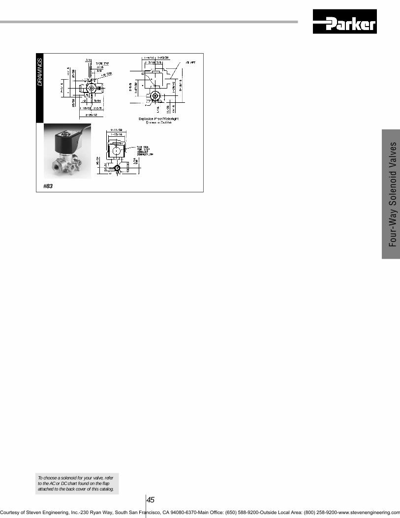
To choose a solenoid for your valve, referto the AC or DC chart found on the flapattached to the back cover of this catalog.
Four
-Way
Sol
enoi
d Va
lves
45
#83
DR
AWIN
GS
Courtesy of Steven Engineering, Inc.-230 Ryan Way, South San Francisco, CA 94080-6370-Main Office: (650) 588-9200-Outside Local Area: (800) 258-9200-www.stevenengineering.com

Gold Ring Specialty Specifications .................... 46-51
Cryogenic Two-Way Specifications ...................... 47-48Vacuum Service Two-Way Specifications.................... 49Long Life, Quiet Operating Specifications .............. 50-51
Specialty Valve Contents
Courtesy of Steven Engineering, Inc.-230 Ryan Way, South San Francisco, CA 94080-6370-Main Office: (650) 588-9200-Outside Local Area: (800) 258-9200-www.stevenengineering.com

To choose a solenoid for your valve, referto the AC or DC chart found on the flapattached to the back cover of this catalog.
MechanicalCharacteristics
Standard Materials of Construction• Body-Brass or 303 Stainless Steel as listed• Seals-PTFE, Urethane or PCTFE, Lead-Clad
Copper in 1/8-3/8-inch NPT Valves • Plunger and Pole Piece-430FR or 49FM
Stainless Steel• Plunger Tube-305 Stainless Steel• Springs-302 Stainless Steel• Shading Coil-Copper (Brass Bodies),
Silver (Stainless Steel Bodies)• Disc Holder (Normally Open Valves)-
303 Stainless Steel
Compatible Fluids• Cryogenic Service solenoid valves are designed
to withstand the severe temperatures associatedwith controlling cryogenic fluids at temperaturesto -320°F(-196°C). Due to the sealing materialsavailable for use at extremely low temperatures,slight leakage can be expected.
Electrical Characteristics
Voltages• AC-24/60, 110/120-50/60, 220/240-50/60
Coil• Class F Standard,
Miscellaneous
Temperature Ratings (media as listed)• AC Voltages: 150°F max.• DC Voltages: -320°F max.• Ambient: 32-77°F (standard)• Cryogenic and Liquid CO2 valves are not
available with explosion proof coils.
Installation• Important: Use downstream piping with an inside
diameter no larger than the valve orifice toprevent expanding CO2 from freezing the valve.Consult factory for dimensional information.
• Valves are supplied with a mounting bracket fordirect mounting. A 1/8-inch NPT port issupplied for remote mounting.
SPECIFICATIONS
GOLD RING Two-Way Normally ClosedCryogenic Service and Liquid CO2 Valves
BRASS VALVES– NORMALLY CLOSED PTFE SEALSAC VALVE SPECIFICATIONS
Orifice Diameter Flow Factor Operating Pressure Differential Min. Temp. Max. Temp.NPT Max. (MOPD) ValvePipe Min. Cryogenic Fluids Liquid AC PartSize inch mm Cv Kv (PSI/Bar) (PSI/BAR) CO2 °F °C °F °C Watt Number1/4 7/32 5.56 .56 0.48 0 0.00 70 4.83 - -320 -196 150 66 16.0 04F20C2414CDF-L3/8 7/32 5.56 .56 0.48 0 0.00 70 4.83 - -320 -196 150 66 16.0 06F20C2414CDF-L1/2 5/8 15.88 3.8 3.28 0 0.00 150 13.79 - -320 -196 150 66 11.0 08FH6C2440ACF-L
47
Spec
ialty
Val
ves
Courtesy of Steven Engineering, Inc.-230 Ryan Way, South San Francisco, CA 94080-6370-Main Office: (650) 588-9200-Outside Local Area: (800) 258-9200-www.stevenengineering.com

DC VALVE SPECIFICATIONS
Orifice Diameter Flow Factor Operating Pressure Differential Min. Temp. Max. Temp.NPT Max. (MOPD) ValvePipe Min. Liquid CO2 AC PartSize inch mm Cv Kv (PSI/Bar) (PSI/BAR) °F °C °F °C Watt Number
1/8 3/64 1.19 .06 0.05 0 375 - -75 -59 120 49 9.5 02F20C35O3A1F
LIQUID CO2 SERVICE STAINLESS STEEL VALVES– NORMALLY CLOSED, URETHANE SEALSAC VALVE SPECIFICATIONS
Orifice Diameter Flow Factor Operating Pressure Differential Min. Temp. Max. Temp.NPT Max. (MOPD) ValvePipe Min. Liquid CO2 AC PartSize inch mm Cv Kv (PSI/Bar) (PSI/BAR) °F °C °F °C Watt Number
1/8 3/64 1.19 .06 0.05 0 1125 77.60 -75 -59 120 49 10.2 02F20C3503ABF-431/8 3/32 2.38 .20 0.17 0 300 20.69 -75 -59 120 49 10.2 02F20C3506ABF-43
Spec
ialty
Val
ves
48
Ordering Information
Parker Gold Ring solenoid valves for cryogenic or liquid CO2 service areavailable as complete valves only.
1.) Select the valve required by pipe size, Cv and pressure and temperaturerequirements.
2.) Select one enclosure, one coil termination and one voltage code from eachcolumn. Note: 18” leads are standard.
3.) Complete the part number with suffix L or 43 as indicated in the table.Example: 04F20C2414CDF4C05L.
Two-Way Cryogenic Service and Liquid CO2 Valves
Courtesy of Steven Engineering, Inc.-230 Ryan Way, South San Francisco, CA 94080-6370-Main Office: (650) 588-9200-Outside Local Area: (800) 258-9200-www.stevenengineering.com

MechanicalCharacteristics
Standard Materials of Construction• Body-Brass• Seals-Low and Medium Vacuum : NBR, High
Vacuum: FKM• Plunger and Pole Piece-430FR Stainless Steel• Plunger Tube-305 Stainless Steel• Springs-302 Stainless Steel• Shading Coil-Copper• Disc Coil (Normally Open Valves)-Ryton
Compatibility• Vacuum service solenoid valves are suitable for
use with the following vacuum ranges asindicated in the specification table. Operatingpressure differentials on some valves may renderthe valve unsuitable for certain vacuumapplications. Verify pressure differentialrequirements before installing.
Low Vacuum
760 to 25 Torr (O psi to 29 in. Hg)
Medium Vacuum
25 to 10-3 Torr (29 in. Hg to 1 micron)
High Vacuum
10-3 to 10-6 Torr (1 to 10-3 microns)
Electrical Characteristics
Voltages• AC-24/60, 110/120-50/60, 220/240-50/60
Coil• Class F Standard, Class H Available
Miscellaneous
Temperature Ratings • AC Voltages: 180°F max.• Ambient: 32-77°F (standard)• For temperature variations, consult the factory.
Installation• For proper operation, solenoid valves should be
mounted vertical and upright. Dimensions areshown in the standard series section. Refer tothe appropriate sections for nominal dimensions.For certified drawings, consult factory.
49
Spec
ialty
Val
ves
To choose a solenoid for your valve, referto the AC or DC chart found on the flapattached to the back cover of this catalog.
SPECIFICATIONS
GOLD RING Two-Way Low, Medium andHigh Vacuum Service Valves
BRASS VALVES– NORMALLY CLOSED, NBR OR FKM SEALSAC VALVE SPECIFICATIONS
Orifice Diameter Flow Factor Operating Pressure Differential Low Vacuum Med. Vac. High Vacuumto to to
29” Hg 10-3 Torr 10-6 TorrMinimum Maximum AC Valve Add Valve
NPT inch mm Cv Kv (PSI/Bar) (PSI/Bar) Watt Part No. Suffix Part No.
1/4 9/32 7.14 .96 0.83 0 15 1.03 6.0 04F20C2118AAF S 04F20C2218AAF-V3/8 5/16 7.94 1.40 1.21 0 15 1.03 6.0 06F20C2120AAF S 06F20C2220AAF-V1/2 7/16 11.11 2.80 2.41 0 15 1.03 16.0 08F20C2128ADF S 08F20C2228ADF-V3/4 3/4 19.05 5.00 4.31 0 4 0.28 16.0 12F20C2148ADF S 12F20C2248ADF-V3/4 3/4 19.05 5.00 4.31 0 15 1.03 11.0 12F23C2140ACF S 12F23C2248ACF-V1 1 25.40 12.2 10.52 0 15 1.03 16.0 16FH5C2164ADF S 16FH5C2264ADF-V
BRASS VALVES– NORMALLY OPEN NBR OR FKM SEALSAC VALVE SPECIFICATIONS
Orifice Diameter Flow Factor Operating Pressure Differential Low Vacuum Med. Vac. High Vacuumto to to
29” Hg 10-3 Torr 10-6 TorrMinimum Maximum AC Valve Add Valve
NPT inch mm Cv Kv (PSI/Bar) (PSI/Bar) Watt Part No. Suffix Part No.
3/8 5/8 15.88 3.00 2.59 0 15 1.03 11.0 06F23O2140ACF S 06F23O2240ACF-V1/2 5/8 15.88 4.00 3.45 0 15 1.03 11.0 08F23O2140ACF S 08F23O2240ACF-V3/4 3/4 19.05 5.00 4.31 0 15 1.03 11.0 12F23O2148ACF S 12F23O2248ACF-V
For DC applications and stainless steel bodied valves, consult factory.
Courtesy of Steven Engineering, Inc.-230 Ryan Way, South San Francisco, CA 94080-6370-Main Office: (650) 588-9200-Outside Local Area: (800) 258-9200-www.stevenengineering.com

52
TechnicalInformationIntroduction
Solenoid valves are highly engineered products thatcan be utilized in many diverse and unique applica-tions. In addition to operational functionality, it isimportant to consider safety, reliability, media compatibility and suitability for the operatingenvironment when selecting the best product for agiven application. This section provides a briefoverview of the components and functional varietiesof solenoid valves available from Parker.
General Information
OperationSolenoid valves are electrically operated devicesused to control flow. They are used for the remoteon/off or directional control of liquids, gases andsteam. They do not regulate flow.
Solenoid valves consist of two main elements: 1.) An electrical coil in the solenoid, and 2.) Avalve body or pressure vessel. The solenoid is theelectromagnetic unit that powers (acts to open orclose) the valve. The valve is the pressure contain-ing unit that acts to shut off or open media flow.
When the solenoid is energized by an electricalsignal, current flow results in the build up of amagnetic field. The field attracts a moveableplunger in the valve. Physical movement of theplunger opens or closes a valve orifice which givesthe valve on/off or directional control of media.
In general, solenoid valves are constructed to be:1.) Normally-Open, or 2.) Normally-Closed. Bothdesignations refer to action of the valve on flowwhen the solenoid is not energized. There wouldbe, for example, no media flow through a normally-closed valve until the solenoid is energized.
The most common types of solenoid actuatedvalves are: 1.) Direct-Acting, and 2.) Pilot-Operated. In a direct-acting valve, the plunger is indirect contact with the body main orifice, and opensor closes the orifice. In a pilot-operated valve, themain orifice is not directly controlled by the plunger,but by a diaphragm, piston or spool. Pilot operatedvalves contain both a pilot and a bleed orifice.
Operational SpecificationsAll solenoid valves are individually rated forMaximum Operating Pressure Differential(MOPD). This is the maximum differential pressure
between the inlet and outlet sides of the valve againstwhich the solenoid can safely operate the valve.
Pilot-operated solenoid valves may also have anadditional specification, Minimum OperatingPressure Differential (MOP). This is theminimum system pressure differential required tooperate the valve and maintain it in the openposition. MOP applies only to pilot-operatedsolenoid valves where system pressure is used tolift the diaphragm off the seat (normally-closed)when the solenoid is energized. Direct-acting orhung-diaphragm valves do not require a minimumoperating pressure.
There will be a pressure differential ³P before thesolenoid of a normally-closed valve is energized.Just after flow begins moving through the valve, thepressure differential may decrease. When sizing anynormally-closed, normally-open, or universalsolenoid valve, pressure differential before and afterflow begins must be considered.
Solenoid valves are also rated for MaximumFluid (media) Temperature due to temperaturelimitations of the various disc or diaphragmmaterials used in their construction.
Response Time, the time necessary for a fullyopen valve to fully close, or the time necessary for afully closed valve to fully open, is affected byseveral factors including: electrical service, media,valve, size, system pressure, pressure drop, andoperating mode.
The following general response times (nominal)apply for air service using alternating current.
• Small direct-acting valves (1/8 to 1/4-inch) .5 to 10 milliseconds
• Large direct-acting valves(3/8 to 3/4-inch) 20 to 40 milliseconds
• Small pilot (diaphragm) valves (3/8 to 3/4-inch) 15 to 50 milliseconds
• Large pilot (diaphragm) valves (1 to 3-inch) 50 to 75 milliseconds
Viscous liquids have very little effect on responsetime on small direct-acting valves. However, on allother valves, viscous liquids may increase responsetime by 50 to 100 percent.
DC operated solenoid valves will generallyincrease response time (relative to AC operatedsolenoids) by as much as 50 percent. Whereresponse time is critical, consult your authorizedlocal Fluid Control Division distributor.
Two-Way Solenoid Valve Operation
Two-way solenoid valves have one inlet and oneoutlet connection with one main orifice and flowpath. A normally closed valve is closed when thesolenoid is de-energized, open when the solenoidis energized. A normally open valve is open whenthe solenoid is de-energized, closed when thesolenoid is energized. Consideration should begiven to the desired fail-safe condition of the valvewhen selecting the type of operation.
Operational Sequence: Direct-Acting Normally Closed
To Open: When the solenoid receives an electricalsignal, a magnetic field is formed which attracts theplunger. The plunger lifts off the main orificeallowing flow through the valve.
Normally Closed, De-Energized
To Close: When the solenoid is de-energized, itreleases its hold on the plunger. The plunger dropsand covers the main orifice.
Normally Closed, Energized
Courtesy of Steven Engineering, Inc.-230 Ryan Way, South San Francisco, CA 94080-6370-Main Office: (650) 588-9200-Outside Local Area: (800) 258-9200-www.stevenengineering.com

53
Operational Sequence: Direct-Acting Normally Open
In a normally open valve, the sequence of operationis reversed from that of a normally closed valve.The main orifice is open when the solenoid is de-energized.
To Close: When the solenoid is energized, itattracts the plunger. The plunger covers the mainorifice stopping media flow through the valve.
Normally Open, De-energized
To Open: When the solenoid is de-energized, it re-leases its hold on the plunger. The plunger uncoversthe main orifice allowing flow through the valve.
Normally Open, Energized
Operational Sequence: Pilot-Operated Normally Closed
To Open: When the solenoid receives an electricalsignal, a magnetic field is formed which attracts theplunger. The plunger covering the pilot orifice liftsoff, causing system pressure (holding thediaphragm closed) to drop.
As system pressure on top of the diaphragm isreduced, full system pressure on the opposite sideof the diaphragm acts to lift the diaphragm awayfrom the main orifice, thus allowing full media flowthrough the valve. Since the bleed orifice isdimensionally smaller than the pilot orifice, systempressure cannot rebuild on top of the diaphragm aslong as the pilot orifice remains open.
Normally Closed, De-Energized
To Close: When the solenoid is de-energized, itreleases its hold on the plunger. The plunger dropsand covers the main orifice. System pressure thenbuilds up on top of the diaphragm through the bleedorifice, forcing the diaphragm down until it coversthe main orifice and stops media flow through thevalve.
Normally Closed, Energized
Operational Sequence: Pilot-OperatedNormally Open
In a normally open valve, the sequence of operationis reversed from that of a normally closed valve.The main orifice is open when the solenoid is de-energized. All other relationships (e.g., the sizerelationship between the pilot and bleed orifice) stillapply.
To Close: When the solenoid is energized, itattracts the plunger. The plunger covers the pilotorifice. System pressure then builds up on top ofthe diaphragm through the bleed orifice, forcing thediaphragm down until it covers the main orifice andstops media flow through the valve.
Normally Open, De-Energized
To Open: When the solenoid is de-energized, itreleases its hold on the plunger. The plungeruncovers the pilot orifice causing system pressureholding the diaphragm closed to drop. As systempressure on top of the diaphragm is reduced, fullsystem pressure on the opposite side of thediaphragm acts to lift the diaphragm away from themain orifice, thus allowing full media flow throughthe valve.
Normally Open, Energized
Courtesy of Steven Engineering, Inc.-230 Ryan Way, South San Francisco, CA 94080-6370-Main Office: (650) 588-9200-Outside Local Area: (800) 258-9200-www.stevenengineering.com

Three-Way Solenoid Valve Operation
The difference between two-, three- and four-waysolenoid valves lies in the construction of the valvebody. Three-way valves have three connections andtwo main orifices. One orifice is always closed, theother always open. Which orifice is open, andwhich is closed, determines whether the valve isoperationally normally open or normally closed.
Operational Sequence:
Direct-Acting Normally Closed
As with a normally closed, two-way valve, thesystem pressure orifice is closed when the solenoidis de-energized. The second orifice is open towhatever device it is connected to. When energized,the system pressure orifice is opened and thesecond orifice is closed. This allows systempressure to be applied to the device that waspreviously being exhausted through the secondorifice (now closed).
Normally Open
As with a normally open, two-way valve, the systempressure orifice is open when de-energized. Thesecond orifice is closed to whatever device it isconnected to. With the solenoid energized, thesystem pressure orifice is closed, the second orificeopened and the device exhausted.
Universal Construction
This type of three-way valve may be used in eitherthe normally closed or normally open mode. It canbe piped either way. The valve can be used to divertmedia flow from one outlet connection to the other,or to select one or two inlet flows.
Operational Sequence:
Pilot-Operated Normally Closed
As with pilot-operated two-way valves, the plungermovement controls the pilot orifice which controlsthe pressure holding one of the diaphragms closedagainst the main orifice. As with direct-actingthree-way valves, one orifice is closed when theother is open. When de-energized, flow is from thepressurized device to exhaust and the systempressure port is closed. When energized, flow isfrom the pressure port to the controlled device andthe exhaust port is closed.
Normally Open
Four-Way Solenoid Valve Operation
A four-way valve is generally used to operatedouble-acting cylinders vs. a three-way for single-acting cylinders.
A double-acting cylinder has a port at either endof the cylinder body by which fluid can enter andexit. This allows the piston to be moved (propelled)in either direction (double-acting). To distinguishthe ports on a double-acting cylinder, one is usuallymarked “A” and the other “B”. A four-way solenoidvalve acts to change the direction of fluid flow fromthe “A” port to the “B” port and, therefore, changedirection of the cylinder.
De-Energized
54
Courtesy of Steven Engineering, Inc.-230 Ryan Way, South San Francisco, CA 94080-6370-Main Office: (650) 588-9200-Outside Local Area: (800) 258-9200-www.stevenengineering.com

Energized
In addition to the “A” and “B” cylinder ports, thefour-way valve has a pressure and exhaust port.When de-energized, the pressure port is internallyconnected to the “A” cylinder port, and the “B”cylinder port is internally connected to the valve’sexhaust port. Energizing the four-way valvereverses the system, routing the “A” port to exhaustand the “B” port to pressure. A minimum pressuredrop is required for proper operation. Care shouldbe taken not to restrict the exhaust port.
General Data-SolenoidCoils
Power and VoltageAll coils used in Gold Ring solenoid valves aredesigned for continuous duty except where noted.On AC, inrush current occurs at the moment thesolenoid is energized. The continuous current afterinrush is holding current. Typical AC current valuesare shown below. DC solenoids have no inrush.Typical amp ratings for DC are determined bydividing DC watts by DC voltage.
All Gold Ring solenoid valves are tested to oper-ate at 15% undervoltage and full pressure ratings.AC and DC voltage ratings (nominal) and normaloperating ranges, as shown in the following table,are standard. For special voltages, consult thefactory.
Holding and Inrush Current
Small, Direct-Acting 2-Way,3-Way and 4-Way Series 20, 30,35, 38, and 48 (1/8 to 3/8”)
2-Way, Direct-Acting Series 20 (3/8 to 3/4”)
Pilot 2-Way Series 22, 23, 24,25, 26, 28, (3/8 to 1-1/2”)
AC/DC Voltage RangeAll coils used in Gold Ring valves are designed forcontinuous duty except where noted. They canremain energized continuously without damage fromoverheating or mechanical failure. AC and DC vol-tage ratings (nominal) and normal operating ranges,as shown in the following table, are standard.
All coils used in Gold Ring solenoid valves areeither Class “F” or Class “H” molded epoxy, and areconstructed in accordance with UL, IEEE, NEMA andother accepted standards.
Testing
All Gold Ring solenoid valves are 100% tested.Coil insulation systems must satisfy performancestandards set by the National Electrical Manufac-turers Association (NEMA) and tested by Under-writer’s Laboratories.
Electrical components of AC and DC coils aretested in accordance with ASTM D2307-78 andbecome a recognized component under U.L.1446.The procedure produces data for an evaluationwhich concludes, a coil with 20,000 hourscontinuous operation will perform within the samespecifications of a zero time coil (new coil).
Temperature
Just as fluid (media) temperatures affect valve bodytrim; ambient, fluid and power input temperaturesaffect solenoid coils. The following table withambient temperature at 77°F (25°C) showstemperature limitations of Gold Ring solenoids.
Temperature rise due to power input varies withcoil design. Temperature rise due to power inputand ambient temperature is directly additive andhelps determine the class of coil required forspecific valve applications.
When ambient temperature is greater than 25°C(77°F), add the difference of ambient and 25°C(77°F) to the energized coil temperature shown inthe table.
The effect of higher fluid temperatures needs to beconsidered only when fluid temperature is greaterthan 180°F. Do not exceed the catalogmaximum temperature limitation for the valve.Add the difference of your fluid temperature and180°F to the energized coil temperature shown inthe table.
Use the “Saturated Steam Temperature Table”when working with saturated steam. Do notexceed the catalog maximum temperaturelimitation for the valve. Add the difference ofsteam temperature and 180°F to the energized coiltemperature shown in the table.
55
WATT RATING AND VOLT AMPERAGE
Standard Coil ACInsulation VA VA
Class Watts Holding Inrush
F 6 16 26F 10.2 23 37F 11 20 34F 16 31 50
WATT RATING AND VOLT AMPERAGE
Standard Coil ACInsulation VA VA
Class Watts Holding Inrush
F 6 16 36F 11 20 61F 16 31 88
WATT RATING AND VOLT AMPERAGE
Standard Coil ACInsulation VA VA
Class Watts Holding Inrush
F (Offset Pilot) 6 16 26F (Center Pilot) 6 16 34
F 11 20 53F 16 31 76
AC DC
Nominal Normal Nominal NormalVoltage Operating Voltage OperatingRating Range Rating Range
24 20-24 12 10.2-12.6120 102-120 24 20-25240 204-240
Courtesy of Steven Engineering, Inc.-230 Ryan Way, South San Francisco, CA 94080-6370-Main Office: (650) 588-9200-Outside Local Area: (800) 258-9200-www.stevenengineering.com

56
Total of additional ambient and fluid orsteam temperature to the energized coiltemperature shown must not exceed theindustrial limit of the coil class selected.
Class “H” coil is required if total temperatureexceeds “F” Class coil limits. Consult your FluidControl Division authorized distributor if totaltemperature exceeds the “H” Class coil limit.
Coil Construction
All Gold Ring coils are epoxy encapsulated. Thiscompound is waterproof and impervious to oil,dust, moisture and most corrosive fumes andvapors.
All coils used in Gold Ring valves are molded andconstructed in accordance with UL, IEEE, NEMA andother accepted standards, and are 100% tested.
Valve Sizing
Any given application requires proper sizing of theGold Ring solenoid valve. If the valve selected istoo small, flow conditions will not be met. If toolarge, system cost will be excessive. Gold Ring sol-enoid valves are tested and rated using the industryaccepted Cv method. This method, used in both theU.S. and Europe, is both simple and accurate.
The correct size valve for an application can bedetermined by either using the engineered formulaeshown below, or by using the curves and simplifiedformulae on the following pages.
Using Flow Formulas
Gases
If P2 > P critical
Qm = Cv
If P2 <– P critical
Qm = Cv
Qm = Rate of flow SCFM (Standard Cubic Feet per Minute) at 14.7 psia and 60
degrees F (standard conditions)
Cv = Flow rating of the valve
P1 = Upstream pressure, psia
P2 = Downstream pressure, psia
P critical is approximate 53% P1
³P = Pressure drop across the valve (open position), psi
SG = Specific gravity of gas, relative to air at 14.7 psi and 60 degrees F
(standard conditions)
T = Absolute (degrees Rankine) temperature in degrees F. (460 + degrees F.)
Note*: 520 is 460ÞF + 60ÞF
Liquids
Q = CvQ = Rate of flow, in gallons per minute
Cv = Flow rating of the valve
³P = Pressure drop across the valve (open position), psi
SG = Specific gravity relative to water at 60 degrees F
Steam
If P2 > P critical
W = 3CvIf P2 <– P critical
W = 3CvW = Rate of flow in pounds per hour
Cv = Flow rating of valve
P1 = Upstream pressure, psia
P2 = Downstream pressure, psia
P critical is approximate 57% P1
³P = Pressure drop across the valve (open position), psi
X = Quality of steam (Fraction Dry Steam)Critical pressure has the following significance in the flow of compressible fluids (gases and steam) throughvalves. Assuming a fixed upstream pressure of P1, an increase in flow is obtained as the downstreampressure P2 is reduced below P1. Continuing increases in flow are experienced until P2 is reduced to acritical value (P critical). When P2 is reduced below P critical, no further increase in flow results. P criticalcan be expressed as a percentage of P1 with approximate values (53% to 57%) given above.
Note: PSIA is absolute pressure which is gauge pressure plus atmospheric pressure (14.7 psi at sea level).
P1³P x 520*SG T
P1³P X
³PSG
P1 x 520*2SG T
P12x
Courtesy of Steven Engineering, Inc.-230 Ryan Way, South San Francisco, CA 94080-6370-Main Office: (650) 588-9200-Outside Local Area: (800) 258-9200-www.stevenengineering.com

Definition of Symbols
Cv = Flow coefficient
QL = Liquid flow (GPM)
Qg = Gas flow, standard cu-ft-hr (SCFH)
Qs = Steam flow (lb./hr.)
P1 = Inlet pressure (PSI)
P2 = Outlet pressure (PSI)
³P = Pressure differential (PSI) (P1-P2)
KL = Liquid flow curve factor
Kg = Gas flow curve factor
Ks = Steam flow curve factor
Ksg = Specific gravity factor
Kt = Temperature factor
There will be a pressure differential ³P before thesolenoid of a normally closed valve is energized.Just after flow begins moving through the valve, thepressure differential may decrease.
When sizing any normally closed, normally open,or universal solenoid valve, pressure differentialbefore and after flow begins must be considered.
Curves to correct for specific gravity (Ksg) andtemperature (Kt) are included. These curves applyto liquids and gases only, not saturated steam.
For liquids with viscosity in excess of 300 SSU,consult your Gold Ring authorized distributor orcontact the factory.
The simple and easy to read flow curves forliquids, gases and steam will help in properly sizingvalves.
There is a constant relationship between gas andsaturated steam flow curves. The flow curve forgases can be used for steam by reading the Kssteam scale.
Specific gravity for various compounds are alsoincluded.
The correction for temperature in the range of 20°F to150°F is very small, and, therefore, can be ignored inordinary applications.
Basic Formulae UsingGraphs
Liquid
Cv =
Steam
Cv =
Gas
Cv =
57
QsKs
QLKL x Ksg
QLKg x Ksg x Kt
Courtesy of Steven Engineering, Inc.-230 Ryan Way, South San Francisco, CA 94080-6370-Main Office: (650) 588-9200-Outside Local Area: (800) 258-9200-www.stevenengineering.com
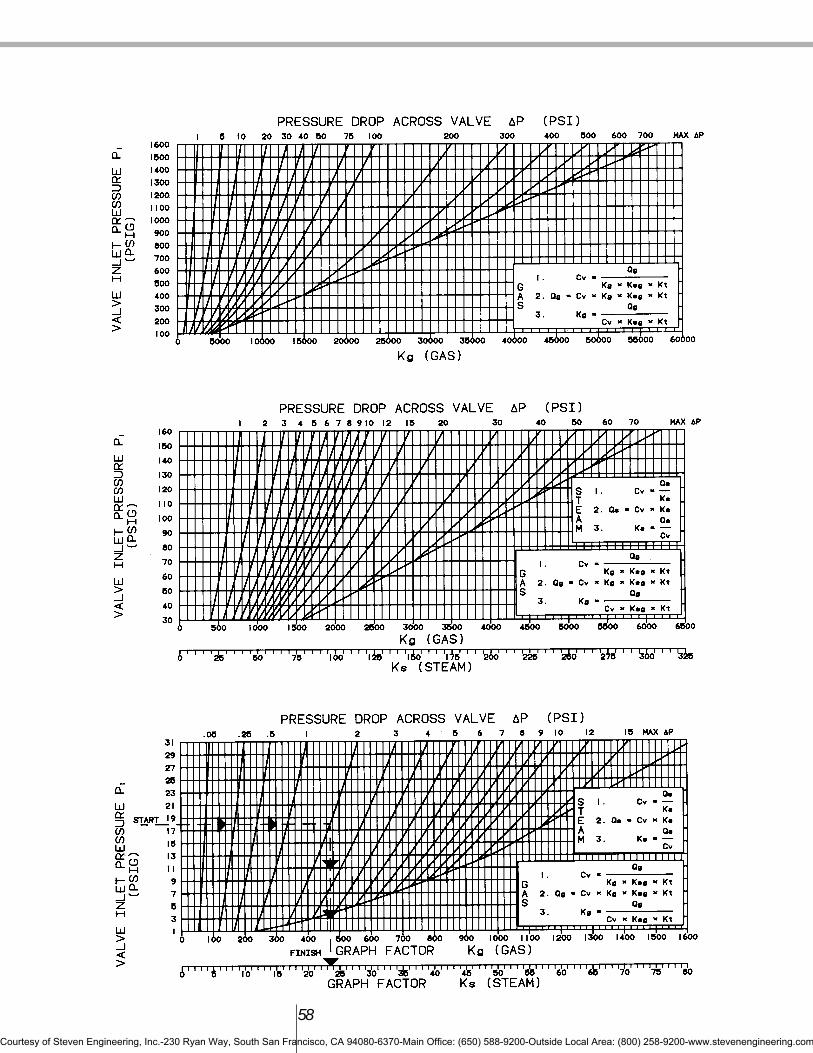
58
Courtesy of Steven Engineering, Inc.-230 Ryan Way, South San Francisco, CA 94080-6370-Main Office: (650) 588-9200-Outside Local Area: (800) 258-9200-www.stevenengineering.com

59
MEDIA KNOWN FIND FORMULA CURVECV, ³P, Ksg QL QL = CV x KL x Ksg Liquids
LiquidsP1, CV, Qg, Ksg ³P KL = Liquids
Apply KL to the liquid factor curve with P1 to find ³P.
CV, Kg, Ksg, Kt Qg Qg = CV x Kg x Ksg x Kt GasesGases
P1, CV, Qg, Ksg, Kt ³P Kg = Gases
Apply Kg to the liquid factor curve with P1 to find ³P.After solving for P (pressure differential), a general rule of 2(³P) will equal the minimum pressure for a required flow.
CV, ³P Qs Qs = CV x Ks Gases Steam ScaleSteam*
P1, CV, Qs ³P Ks = Gases Steam Scale
Apply Ks to the liquid factor curve with P1 to find ³P.* In all cases, steam is considered saturated.
QLCv x Ksg
QgCv x Ksg x Kt
Sample Problems
Problem: Liquids
Determine Cv when the required flow is 30 GPM,media is light oil with a specific gravity of 0.82,inlet pressure (P1) is 36 PSI and outlet pressure(P2) is 0 (³P = 36 PSI).
Solution
Use the formula:
Cv =
From the liquid flow curve using the pressure drop(36 PSI), read vertically up to the curve. Readhorizontally to KL= 6.
From the specific gravity curve using the specificgravity value (0.82), read vertically to the curve.Read horizontally to Ksg=1.1.
From the formula:
Cv =
Cv =
Cv = 4.5
Problem: Air and Gases
Determine Cv when the required flow is 700 SCFH,media is air (sg=1.0), inlet pressure (P1) is 70 PSI,outlet pressure (P2) is 55 PSI, ³P (P1 - P2) = 15 PSI,and air is at 50°F.
Solution
Use the formula:
Cv =
From the gas and steam flow curve using the inletpressure (70 PSI), read horizontally to the curve forpressure drop (³P=15 PSI). Read vertically down toKg = 2025.
Air at (50°F) falls into an area of the temperaturecorrection curve where Kt is approximately 1 andcan be ignored.
Cv =
Cv =
Cv = 0.35
Steam
Determine Cv when the required flow is 30 lb./hr.,media is saturated steam, inlet pressure (P1) is 80PSI, outlet pressure (P2) is 60 PSI and ³P (P1 - P2)is 20 PSI.
Solution
Use the formula:
Cv =
Remembering that the gas and steam flow curveshave been combined, from the gas and steam flowcurve using the inlet pressure value (80 PSI) readhorizontally to the curve for the pressure drop(³P=20PSI). Read vertically down to KS = 121.
From the formula:
Cv =
Cv = 0.25
Formula Variations
The examples used here for liquids, gases, andsteam show how to determine Cv. These sameformulae can be transposed to determine otheruseful data once a specific value has been selectedto meet the desired Cv (see formula variations tableon page 59).
QLKL x Ksg
QgKg x Ksg x Kt
30 (GPM)6 x 1.1
306.6
7002025 x 1.0700
2025
QsKs
30121
QsCv
Courtesy of Steven Engineering, Inc.-230 Ryan Way, South San Francisco, CA 94080-6370-Main Office: (650) 588-9200-Outside Local Area: (800) 258-9200-www.stevenengineering.com

60
Saturated Steam Temperature TableHeat of Latent Total
` Sat. Heat of Heat ofTemp. Liquid Evap. Steam
PSIA PSIG °F (BTU/lb)(BTU/lb)(BTU/lb)
15 1 213 181.2 969.7 1150.920 5 227 196.2 960.1 1156.330 15 250 218.9 945.2 1164.140 25 267 236.1 933.6 1169.750 35 281 250.2 923.9 1174.160 45 292 262.2 915.4 1177.670 55 302 272.7 907.8 1180.580 65 312 282.1 900.9 1183.090 75 320 290.7 894.6 1185.3100 85 327 298.5 888.6 1187.1110 95 334 305.8 883.1 1188.9120 105 341 312.6 877.8 1190.4130 115 347 319.0 872.8 1191.8140 125 353 325.0 868.0 1193.0150 135 358 330.6 863.5 1194.1
Fluid Compatibility
General Information
The following table lists many of the liquids andgases commonly considered for handling withsolenoid valves. In some cases, specific limitationsare listed, and in other cases, Gold Ring solenoidvalves are not recommended. For media not listedin the tables, consult the factory for specificrecommendations.
Trim MaterialsBuna “N” (Nitrile) Symbol NBRA soft synthetic compound, Buna “N” is the mostwidely used elastomer in industry today. Buna “N”is standard disc and diaphragm material in GoldRing solenoid valves. It has excellent servicecharacteristics for use with water, light oil and gasin a temperature range of (-10°F) to 180°F.
Ethylene Propylene Symbol EPIntroduced to the rubber industry in 1961, Ethylene
Propylene is used primarily for applicationsinvolving hot water or steam service. It hasexcellent service characteristics for many liquids ina temperature range from (-10°F) to 300°F.
Viton* Symbol VA soft fluoroelastomer, Viton was originally developedto handle hydrocarbons including gasoline, jetengine fuels and various solvents. It handles mediain a broader temperature range than EthylenePropylene. Its temperature range extends from (-10°F) to 350°F. Viton is also an ideal material forhandling a wide range of chemical media.
Teflon* Symbol TAnother fluorocarbon, Teflon is available as a solidmaterial or combined with fillers. Teflon will with-stand chemical attack from almost any fluid. Itstemperature range extends from (-320°F) to 350°F.Because it is not easily fabricated and known tohave cold flow characteristics, its applications arelimited.
* DuPont Co. Trademark
Liquid Gas Liquid Gas
Acetic Acid, 10% 1.01 - Liquid petroleum 0.06 2.067Acetic Acid, Pure 1.06 - Gas (LPG)Acetone 0.79 - Mercury 13.6 -Acetylene 0.60 0.91 Methane 0.50 0.554Alcohol Amyl 0.81 - Mineral Oil, USP 0.89 -Alcohol Ethyl 0.79 - Motor Oil-SAE 0.89 -
(Ethanol) #10, etc.Alcohol Methyl 0.81 - Naptha 0.76 -
(Methanol) Natural Gas 0.55 0.554Ammonia 0.93 0.596 Oxygen 1.15 1.105Ammonium Nitrate 1.72 - Perchloroethylene 1.50 -Ammonium Phosphate 1.69 - Petroleum Oils 0.89 -Argon Gas 1.40 1.379 Potassium Sulfate 1.05 -Beer 1.01 - Prestone Anti-Freeze 1.03 -Benzene Benzol 0.88 - Propane 1.10 1.56(Benzene) Pydraul (Mansanto) 1.28 -Butadiene (Gas) 0.65 2.00 Sodium Hydroxide (100%) 2.13 -Butane (L.P. Gas) 0.60 2.067 Sodium Hydroxide (50%) 1.45 -Carbon Dioxide Dry - 1.53 (Caustic Soda)Carbon Disulfide 1.26 - Steam Condensate 1.00 0.62Carbon Tetrachloride 1.59 - Stoddards Solvent 0.80 -Cellulube 0.91 - Sulfuric Acid (10%) 1.08 -Coffee 1.05 - Toluene (Toluol) 0.87 -Corn Oil 0.92 - Transmission Fluid 0.90 -Cottonseed Oil 0.90 - (Type A)Diesel Fuel 0.88 - Trichloroethylene 1.36 -Distilled Water 1.00 0.62 Turpentine 0.87 -Ethylene Glycol 1.11 - Vegetable oils 0.92 -Fatty Acids 0.92 - Vinegar 1.01 -Formaldehyde 0.82 - WaterFreon BF (Solvent) 1.57 - Carbonated 1.00 0.62Freon MF (Solvent) 1.48 - Distilled 1.00 0.62Freon TF (Solvent) 1.57 - Fresh 1.01 0.65Fuel Oils 0.88 - Boiler Feed 1.00 0.62Gasoline 0.68 - Return Condensate 1.00 0.62Heptane (Liquid) 0.68 - Brackish 1.02 0.67Hydraulic Oil 0.91 - Sea 1.03 0.68Hydrogen 0.07 0.0696JP4-5 Fuel 0.79 -Kerosene 0.81 -Linseed Oil 0.94 -
Specific Gravity For Liquids And Gases
Courtesy of Steven Engineering, Inc.-230 Ryan Way, South San Francisco, CA 94080-6370-Main Office: (650) 588-9200-Outside Local Area: (800) 258-9200-www.stevenengineering.com

Neoprene Symbol CRMost elastomers are resistant to either petroleumlubricants or oxygen. Neoprene has limitedresistance to both. Combining wide spectrum ofresistance with a temperature range of (-10°F) to180°F account for its use in many applications.
Urethane Symbol UA synthetic compound, Urethane is widely usedwhere high strength and abrasive resistance arerequired. Its temperature range is similar to Buna"N" (-10°F) to 160°F.
Guide to Media and Material Compatibility for Gold Ring Solenoid Valves
Key:
A = Aluminum1
AT = Acetal
BR = Brass
C = Copper
CE = Celcon
CR = Neoprene
EP = Ethylene Propylene
NBR = Buna “N”
S = Silver
SS = Stainless Steel2
T = Teflon®
U = Urethane
V = Viton®
1 Available by special order only.2 Stainless Steel 302, 303, 305, 316
Applications shown on the next page are based onknown usage or authoritative sources. Factors oftemperature, pressure and concentration may rendermaterial compatibility unacceptable.
61
Trim Material Availability by Valve Series
Pipe FoodSize Orifice Grade
Series NPT Size EP EP T V CR NBR
20 1/8-3/8 3/64-9/32 X X X* X X X20 3/8-3/4 5/16-3/4 X X X
22, 23, 24 3/8-1-1/2 5/8-1-1/2 X X X X X25 1/4-3/8 11/32 X X X25 3/8-1 1/2-1 X X* X26 2-3 2-3 X X28 1/4-3/4 5/16-3/430 1/8-1/4 All X X X* X X X34 3/8-3/4 All X X X48 1/4 All X
Note: Use of Teflon trim materials reduces catalog pressure ratings by 25%.For alternate trim materials, consult factory.
Viton® and Teflon® are Dupont Co. trademarks. Rulon®AR is a Furon-Advanced Polymers Division trademark..
SEAL MATERIAL DESIGNATIONSASTM Commercial Designations
Designation and/or Trade Names
NBR Buna-N, Nitrile
EPDM Ethylene Propylene
FKM Fluorinated Hydrocarbon, Viton®
PCTFE Kel-F
PTFE Teflon®, Rulon®
PFPM Kalrez
CR Neoprene
Courtesy of Steven Engineering, Inc.-230 Ryan Way, South San Francisco, CA 94080-6370-Main Office: (650) 588-9200-Outside Local Area: (800) 258-9200-www.stevenengineering.com
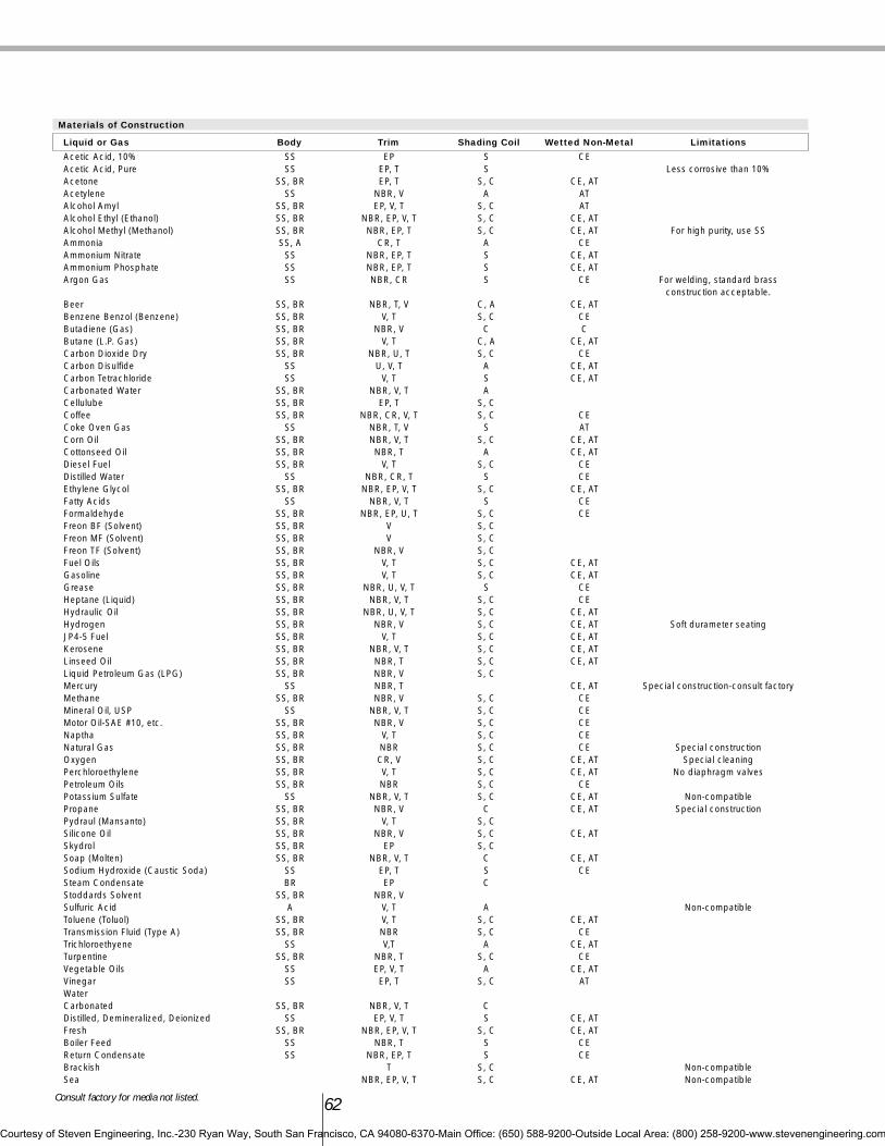
62
Materials of Construction
Liquid or Gas Body Trim Shading Coil Wetted Non-Metal Limitations
Acetic Acid, 10% SS EP S CEAcetic Acid, Pure SS EP, T S Less corrosive than 10%Acetone SS, BR EP, T S, C CE, ATAcetylene SS NBR, V A ATAlcohol Amyl SS, BR EP, V, T S, C ATAlcohol Ethyl (Ethanol) SS, BR NBR, EP, V, T S, C CE, ATAlcohol Methyl (Methanol) SS, BR NBR, EP, T S, C CE, AT For high purity, use SSAmmonia SS, A CR, T A CEAmmonium Nitrate SS NBR, EP, T S CE, ATAmmonium Phosphate SS NBR, EP, T S CE, ATArgon Gas SS NBR, CR S CE For welding, standard brass
construction acceptable.Beer SS, BR NBR, T, V C, A CE, ATBenzene Benzol (Benzene) SS, BR V, T S, C CEButadiene (Gas) SS, BR NBR, V C CButane (L.P. Gas) SS, BR V, T C, A CE, ATCarbon Dioxide Dry SS, BR NBR, U, T S, C CECarbon Disulfide SS U, V, T A CE, ATCarbon Tetrachloride SS V, T S CE, ATCarbonated Water SS, BR NBR, V, T ACellulube SS, BR EP, T S, CCoffee SS, BR NBR, CR, V, T S, C CECoke Oven Gas SS NBR, T, V S ATCorn Oil SS, BR NBR, V, T S, C CE, ATCottonseed Oil SS, BR NBR, T A CE, ATDiesel Fuel SS, BR V, T S, C CEDistilled Water SS NBR, CR, T S CEEthylene Glycol SS, BR NBR, EP, V, T S, C CE, ATFatty Acids SS NBR, V, T S CEFormaldehyde SS, BR NBR, EP, U, T S, C CEFreon BF (Solvent) SS, BR V S, CFreon MF (Solvent) SS, BR V S, CFreon TF (Solvent) SS, BR NBR, V S, CFuel Oils SS, BR V, T S, C CE, ATGasoline SS, BR V, T S, C CE, ATGrease SS, BR NBR, U, V, T S CEHeptane (Liquid) SS, BR NBR, V, T S, C CEHydraulic Oil SS, BR NBR, U, V, T S, C CE, ATHydrogen SS, BR NBR, V S, C CE, AT Soft durameter seatingJP4-5 Fuel SS, BR V, T S, C CE, ATKerosene SS, BR NBR, V, T S, C CE, ATLinseed Oil SS, BR NBR, T S, C CE, ATLiquid Petroleum Gas (LPG) SS, BR NBR, V S, CMercury SS NBR, T CE, AT Special construction-consult factoryMethane SS, BR NBR, V S, C CEMineral Oil, USP SS NBR, V, T S, C CEMotor Oil-SAE #10, etc. SS, BR NBR, V S, C CENaptha SS, BR V, T S, C CENatural Gas SS, BR NBR S, C CE Special constructionOxygen SS, BR CR, V S, C CE, AT Special cleaningPerchloroethylene SS, BR V, T S, C CE, AT No diaphragm valvesPetroleum Oils SS, BR NBR S, C CEPotassium Sulfate SS NBR, V, T S, C CE, AT Non-compatiblePropane SS, BR NBR, V C CE, AT Special constructionPydraul (Mansanto) SS, BR V, T S, CSilicone Oil SS, BR NBR, V S, C CE, ATSkydrol SS, BR EP S, CSoap (Molten) SS, BR NBR, V, T C CE, ATSodium Hydroxide (Caustic Soda) SS EP, T S CESteam Condensate BR EP CStoddards Solvent SS, BR NBR, VSulfuric Acid A V, T A Non-compatibleToluene (Toluol) SS, BR V, T S, C CE, ATTransmission Fluid (Type A) SS, BR NBR S, C CETrichloroethyene SS V,T A CE, ATTurpentine SS, BR NBR, T S, C CEVegetable Oils SS EP, V, T A CE, ATVinegar SS EP, T S, C ATWaterCarbonated SS, BR NBR, V, T CDistilled, Demineralized, Deionized SS EP, V, T S CE, ATFresh SS, BR NBR, EP, V, T S, C CE, ATBoiler Feed SS NBR, T S CEReturn Condensate SS NBR, EP, T S CEBrackish T S, C Non-compatibleSea NBR, EP, V, T S, C CE, AT Non-compatible
Consult factory for media not listed.
Courtesy of Steven Engineering, Inc.-230 Ryan Way, South San Francisco, CA 94080-6370-Main Office: (650) 588-9200-Outside Local Area: (800) 258-9200-www.stevenengineering.com

P.N. MA99-0073/8” and 1/2” NPT Series S5 or 25
Available as “W” suffix option
63
1 & 2 3 4 5 6 7 8 9 & 10 11Connection Size Connection Type Construction Operation Body Material Trim Orifice Size Current Design
Series Designation
02 1/8” F Female Pipe 2 2-way 0 Direct Acting C Normally Closed 1 Brass (Bar Stock) 1 NBR Valve orifice diameter in 1/64-inch Thread NPT increments. Example: a 1/2-inch
orifice diameter has an orifice sizedesignation of 32.
04 1/4” 3 3-way 2 Diaphragm Center O Normally Open 2 Brass (Forging) 2 FKMpilot
06 3/8” 4 4-way 3 Diaphragm Hung U Universal 3 303 Stainless 3 EPDMSteel (Bar)
08 1/2” H Diaphragm, 4 Diaphragm Offset S 4-Way Single 5 Brass Nickel Plate 4 PTFEHung pilot Solenoid
12 3/4” 5 Diaphragm, 5 Diaphragm 6 316 Stainless 5 UrethanePivoted Edge Pivoted Edge Steel (Cast)
16 1” S Steam 6 Piston 7 Aluminum 6 CR(Bar Stock)
20 1 1/4” 8 Piston piloted 8 316 Stainless 8 FDA EPRSteel (Bar)
24 1 1/2” 9 Bronze (Cast) 9 Kalrez32 2” D Delrin48 3” K KEL F
Part Number
DR
AWIN
GS
Options
Mounting Brackets
Standard Bracket1/4” NPT Stainless Steel 3-Way
A, B or 1 wattage codes P.N. AB99-002
12 13 14 15 16 & 17Coil Wattage AC Coil Wattage DC Coil Class Solenoid Enclosure Coil Termination Coil Voltage AC Coil Voltage DC
(nominal) (nominal)
A 6 Watts 1 9.5 Watts F Standard (Class 155) E Explosion-Proof/Watertight 01 24/60 70 6B 10.2 Watts 3 11.5 Watts H High Temperature (Class 180) G Type 1 Gen. Purpose C 18” Leads (Standard) 02 24/50 75 12C 11 Watts M 316 SS Explosion-Proof/Watertight 05 110/50 120/60 80 24D 16 Watts O Open Frame 10 208/60 90 120
P Epoxy Encapsulated H DIN 15 220/50 240/60 95 125S Type 1 Splice Box K Screw 41 24/60 rectifiedU 316 SS Explosion-Proof/Watertight S Spade 42 120/60 rectifiedW Submersible Splice Box 44 240/60 rectifiedY Explosion-Proof/Watertight with Ground Lead 51 120-240/60Z Grounded M 53 240-480/604 Type 4, 4X
Notes:All options are not available forall sizes and styles. Consult theappropriate sections in this catalog,or contact the factory. Minimums apply.
Courtesy of Steven Engineering, Inc.-230 Ryan Way, South San Francisco, CA 94080-6370-Main Office: (650) 588-9200-Outside Local Area: (800) 258-9200-www.stevenengineering.com

64
Unit Conversion ChartsFractional Conversions
mm inches deciminches
0.79 1/32 0.0311.59 1/16 0.0632.38 3/32 0.0943.18 1/8 0.1253.97 5/32 0.1564.76 3/16 0.1885.56 7/32 0.2196.35 1/4 .02507.14 9/32 0.2817.94 5/16 0.3138.73 11/32 0.3449.53 3/8 0.37510.3 13/32 0.40611.1 7/16 0.43811.9 15/32 0.46912.7 1/2 0.50013.5 17/32 0.53114.3 9/16 0.56315.1 19/32 0.59415.9 5/8 0.62516.7 21/32 0.65617.5 11/16 0.68818.3 23/32 0.71919.1 3/4 0.75019.8 25/32 0.78120.6 13/16 0.81321.4 27/32 0.84422.2 7/8 0.87523.0 29/32 0.90623.8 15/16 0.93824.6 31/32 0.96925.4 1 1.000
Standard Bracket1/8” NPT 2-Way Normally Open
1/8” 3-Way
Series 22, 23 or 34 Available as“W” suffix option
1/4” NPT Brass 2-Way Available as“W” suffix option
Forged Body Bar StocBody
Measures1 inch = 25.4mm1 inch = 2.54cm
1 U.S. gal = 3.785 liters1 Imperial gallon = 4.546 liters
Pressure1 psi = 0.0703 Kg/square cm
1 psi = 27.73 inches water (@60/F)1 psi = 2.036 inches of mercury (@32/F)
1 psi = 51.7 mm of mercury (@32/F)1 psi = 0.0689 bar
Vacuum1 torr = 1 mm mercury1 micron = 0.001 torr
Volumetric Flow Rate1 Cv = 0.862 Kv
(Kv in m3/h5)1gpm = 0.00378 m3/min
TemperatureDegrees C = (Degrees F-32) (5/9)
Degrees F = (Degrees C) (9/5) + 32
Torque1 in lb. = 0.113 Nm
1 in lb. = 1.15 cm Kg
P.N. KC99-003 P.N. MA99-001
P.N. KB99-007 KB99-016
Courtesy of Steven Engineering, Inc.-230 Ryan Way, South San Francisco, CA 94080-6370-Main Office: (650) 588-9200-Outside Local Area: (800) 258-9200-www.stevenengineering.com

65
Manual Operators
Manual operators are available for normally closedvalves in the following series.
Series 30 Manual Operators for Normally Closed, NormallyOpen or Universal Operation.Series 20 Momentary Manual operators are available forNormally Open or Normally Closed operation (1.8" NPT)
Metal Clamp Solenoid Retainer-Suffix J
Metal solenoid retainers are available for hightemperature applications or applications subject tovibration.
Troubleshooting Guide
Gold Ring solenoid valves are manufactured usingthe highest quality materials under close qualitycontrol. All Gold Ring valves are 100% tested priorto shipment. There are only two to four movingparts. The simplicity of operation makes Gold Ringvalves reliable electro-mechanical devices.Failures, however, can occur. Experience has shownfailure is usually the result of either improper
installation or neglected maintenance.This guide will assist you in properly diagnosing
a failure and provide a proper solution to correct thefailure.
The following general procedures must befollowed whether the valve in question is direct-acting or pilot-operated.
General TroubleshootingDiscussion
Note 1) If the valve fails to operate because of aburn-out or shorted coil, the cause of the burn-outmust be determined before the new unit solenoid, orcoil for explosion-proof valves, is installed. Usuallythe cause is in the mechanical portion of the unitbody, therefore, the entire solenoid valve must beinspected.
Note 2) If the coil has failed, a complete GoldRing unit solenoid, or coil for explosion-proofvalves, should be installed. Be sure to turn offall electrical power in the valve circuit prior toany disassembly.
Note 3) If the solution requires the replacementof a defective part or parts, a complete Gold Ringrebuild kit should be used. Be sure all parts in therebuild kit are installed in the valve, not only thepart or parts deemed defective. As this procedurerequires opening the valve body (pressure vessel),be sure to bleed all system pressure to zero. Ifeither the plunger tube assembly or the bonnetscrews are loosened to relieve trapped valvepressure, do so carefully. Do not completelyremove the plunger tube assembly or the bonnetscrews until the bleeding is complete. Refer to theappropriate I & M Sheet for instructions.
Note 4) In most installations, after a solenoidvalve has been energized for a short time, thesolenoid housing will be hot to the touch. This isnot an indication of a failure or possible failure. Itis perfectly normal.
Note 5) Regardless of system size, waterhammer must be considered and controlled toprotect piping systems and solenoid valves from itseffects. Water hammer occurs when the flow of anon-compressible fluid in a pipe is abruptlystopped. Water hammer is not always identified bynoise and vibration. Examine diaphragms, plungerdiscs and other internal parts for tears, distortionand other damage. Replace internal parts with arebuild kit and modify the piping system.Commercially available water hammer arrestersrange from flexible rubber hose, a simple extensionpipe to a type of permanently sealed chamber.
Hints
1.) Never replace a burned-out coil or unit solenoiduntil the cause of the burn-out has beendetermined, ie: missing parts, plugged plungertube, worn plunger, over voltage, etc.
2.) Before reassembly of valve body, if possible,flush out inlet to valve.
3.) Use a flat screwdriver placed on top of plungertube to test magnetic circuit.
4.) If the cause of failure is the presence of foreignmatter, install a strainer or filter in the upstream(inlet) side of the valve.
Symptoms
Five basic symptoms indicate a solenoid valve isnot operating properly to specifications:1.) Failure to operate (shift position) when
energized.2.) Failure to operate (shift position) when de-
energized.3.) Internal or external leakage.4.) Erratic flow.5.) Excessive solenoid noise when energized even
though any of the above symptoms does notexist. (In some AC installations, a very slighthum may be noticeable and is normal.)
Screw MomentaryPipe Type to 100 psi
Series Size (Suffix M) (Suffix U)22,23, 1/2”-3/4” X
Special Handling & CleaningOrder By
Service Description Specifying Suffix
Clean Systems Valve components are degreased to eliminate hydrocarbons and Hforeign particles and are blacklight inspected. Valves are tested with clean nitrogen and are shipped in sealed bags.
Oxygen Valve components are degreased to eliminate oils and foreign particles Oand are blacklight inspected. An oxygen compatible lubricant is usedfor assembly. Valves are tested with clean nitrogen, certified for oxygenservice and shipped in sealed bags.
Degreasers Valve components are degreased to eliminate hydrocarbons and Consult Factoryforeign particles. They are assembled using a non-silicone base lubricant and tested with clean nitrogen. Shipped in a sealed bag.
All series of valves can be ordered with special cleaning or handling. Valves for vacuum or cryogenic applications are supplied using appropriate cleaning and handling techniques.
Courtesy of Steven Engineering, Inc.-230 Ryan Way, South San Francisco, CA 94080-6370-Main Office: (650) 588-9200-Outside Local Area: (800) 258-9200-www.stevenengineering.com

66
Glossary of Terms
Bleed Orifice: An internal orifice which controls theclosing rate of a pilot operated solenoid valve. Alsocalled the equalizer hole.
Bonnet: The upper half of a diaphragm typesolenoid valve.
Cv: See flow coefficient.
Diaphragm: An elastomeric or other material sealwhich covers the main orifice.
Elastomer: Material having elastic properties.These materials are generally used for sealingpurposes.
Enclosure Tube Assembly: The portion of asolenoid valve which houses the plunger.
Flow Coefficient: Abbreviated Cv. The amount offlow in gpm of water that will flow through an orificewith a pressure differential of 1 psi.
Flux Frame: The magnetic steel frame surroundingthe coil which provides for efficient travel ofmagnetic flux. Also called magnetic frameassembly.
Holding Current: The current required to hold theplunger in the energized position. Value is normallyabout one half of inrush current.
Inrush Current: The current at the moment ofenergization of AC voltage coils. This current is ofgreater value than holding current due to lowinductance at the moment of energization. Supplytransformers should be sized using this value.
Media: The fluid flowing through the valve.
MOP: Minimum operating pressure. The minimumpressure a pilot operated valve requires for properoperation.
MOPD: Maximum operating pressure differential.The maximum pressure differential between inletand outlet that a valve is designed to operateagainst.
NEMA: National Electrical ManufacturersAssociation - Recommends suitable materials andconstructions to meet coil enclosure installationtypes.
Pilot Orifice: An internal orifice which controlsopening characteristics of a pilot operated solenoidvalve. In a pilot operated solenoid, the plungercovers the pilot orifice.
Plunger: Moveable portion of a solenoid valveoperator which controls media flow.
Pole Piece: The stationary half of the magneticattractor inside the plunger tube.
Pressure Differential: The difference between inletand outlet pressures.
Safe Working Pressure: Twenty percent of thepressure which causes external leakage. The valveis not expected to operate at this pressure unlessthe MOPD is a value less than the SWP.
Shading Ring: A single coil located in the polepiece in which a secondary flux wave is inducedduring AC current operation.
Solenoid: The electrical portion containing the coiland magnetic frame and/or enclosure.
Specific Gravity: The ratio of the mass of an equalvolume of distilled water at 4°C or of a gas to anequal volume of air or hydrogen under prescribedconditions of temperature and pressure.
Viscosity: The amount of resistance to flow.
Impr
oper
/ No
Volta
ge
Ope
n / S
horte
d Coi
l
Faul
ty E
lect
rical
Circ
uit
Exce
ssive
Am
bien
t / M
edia
Tem
pera
ture
Non-C
ompa
tible
Med
ia
Ove
r Pre
ssur
izatio
n
Miss
ing
/ Loo
se S
olen
oid
Retai
ner
Inco
rrect
ly pi
ped
In S
yste
m
Loos
e Bod
y Ass
embl
y
Dirt In
Val
ve /
Med
ia
Seat
Ero
sion
Wor
n Disc
Wor
n Pl
unge
r / Tu
be /
Pole
Pie
ce
Block
ed P
ilot H
ole
Block
ed B
leed
Hol
e
Torn
/ Hol
e in
Dia
phra
gm
Inad
equa
te F
low
Restri
cted
Out
let
Restri
cted
inle
t
Fails to Close/Shift X X X X X X X X X X X XFails to Open/Shift X X X X X X X X X X X XInternal Leakage X X X X X X XExternal Leakage X X XExcessive Noise/Hum X X X X X XShort Coil Life X X X
Failure Symptom* SeriesAll 22,23,24,25,S3,S5,26,28 34 & 48
* Partial listNote: This check list is intended to serve as a preliminary guide to common valve failure troubleshooting,and is not intended to contain recommendations for proper solenoid valve or systems operation or design. For proper solenoid valve usage, follow manufacturer'srecommendations. Improper system design may result in ineffective valve operation.
Possible Failure Cause*
Courtesy of Steven Engineering, Inc.-230 Ryan Way, South San Francisco, CA 94080-6370-Main Office: (650) 588-9200-Outside Local Area: (800) 258-9200-www.stevenengineering.com
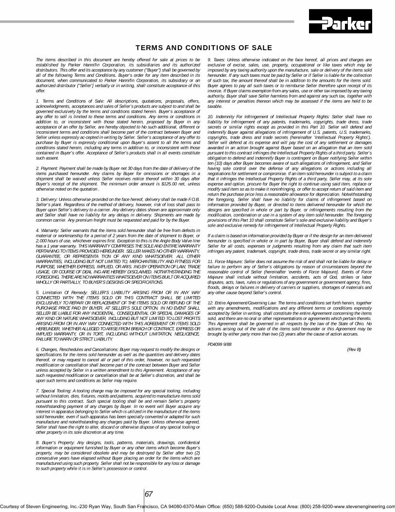
67
The items described in this document are hereby offered for sale at prices to beestablished by Parker Hannifin Corporation, its subsidiaries and its authorizeddistributors. This offer and its acceptance by any customer ("Buyer") shall be governed byall of the following Terms and Conditions. Buyer's order for any item described in itsdocument, when communicated to Parker Hannifin Corporation, its subsidiary or anauthorized distributor ("Seller'] verbally or in writing, shall constitute acceptance of thisoffer.
1. Terms and Conditions of Sale: All descriptions, quotations, proposals, offers,acknowledgments, acceptances and sales of Seller's products are subject to and shall begoverned exclusively by the terms and conditions stated herein. Buyer's acceptance ofany offer to sell is limited to these terms and conditions. Any terms or conditions inaddition to, or inconsistent with those stated herein, proposed by Buyer in anyacceptance of an offer by Seller, are hereby objected to No such additional, different orinconsistent terms and conditions shall become part of the contract between Buyer andSeller unless expressly ac-cepted in writing by Seller. Seller's acceptance of any offer topurchase by Buyer is expressly conditional upon Buyer's assent to all the terms andconditions stated herein, including any terms in addition to, or inconsistent with thosecontained in Buyer's offer. Acceptance of Seller's products shall in all events constitutesuch assent.
2. Payment: Payment shall be made by Buyer net 30 days from the date of delivery of theitems purchased hereunder. Any claims by Buyer for omissions or shortages in ashipment shall be waived unless Seller receives notice thereof within 30 days afterBuyer's receipt of the shipment. The minimum order amount is $125.00 net, unlessotherwise noted on the quotation .
3. Delivery: Unless otherwise provided on the face hereof, delivery shall be made F.O.B.Seller's plant. Regardless of the method of delivery, however, risk of loss shall pass toBuyer upon Seller's delivery to a carrier. Any delivery dates shown are approximate onlyand Seller shall have no liability for any delays in delivery. Shipments are made bycommon carrier. Any premium freight must be requested and paid for by the Buyer.
4. Warranty: Seller warrants that the items sold hereunder shall be free from defects inmaterial or workmanship for a period of 2 years from the date of shipment to Buyer, or2,000 hours of use, whichever expires first. Exception to this is the Angle Body Valve linehas a 1 year warranty. THIS WARRANTY COMPRISES THE SOLE AND ENTIRE WARRANTYPERTAINING TO ITEMS PROVIDED HEREUNDER. SELLER MAKES NO OTHER WARRANTY,GUARANTEE, OR REPRESENTA TION OF ANY KIND WHATSOEVER. ALL OTHERWARRANTIES, INCLUDING BUT NOT LIMITED TO, MERCHANTIBILITY AND FITNESS FORPURPOSE, WHETHER EXPRESS, IMPLIED, OR ARIS. ING BY OPERATION OF LAW, TRADEUSAGE, OR COURSE OF DEAL ING ARE HEREBY DISCLAIMED. NOTWITHSTANDING THEFOREGOING, THERE ARE NO WARRANTIES WHATSOEVER ON ITEMS BUILT OR ACQUIREDWHOLLY OR PARTIALLY, TO BUYER'S DESIGNS OR SPECIFICATIONS.
5. Limitation Of Remedy: SELLER'S LIABILITY ARISING FROM OR IN ANY WAYCONNECTED WITH THE ITEMS SOLD OR THIS CONTRACT SHALL BE LIMITEDEXCLUSIVELY TO REPAIR OR REPLACEMENT OF THE ITEMS SOLD OR REFUND OF THEPURCHASE PRICE PAID BY BUYER, AT SELLER'S SOLE OPTION. IN NO EVENT SHALLSELLER BE LIABLE FOR ANY INCIDENTAL, CONSEQUENTIAL OR SPECIAL DAMAGES OFANY KIND OR NATURE WHATSOEVER, INCLUDING BUT NOT LIMITED TO LOST PROFITSARISING FROM OR IN ANY WAY CONNECTED WITH THIS AGREEMENT OR ITEMS SOLDHEREUNDER, WHETHER ALLEGED TO ARISE FROM BREACH OF CONTRACT, EXPRESS ORIMPLIED WARRANTY, OR IN TORT, INCLUDING WITHOUT LIMITATION, NEGLIGENCE,FAILURE TO WARN OR STRICT LIABILITY.
6. Changes, Reschedules and Cancellations: Buyer may request to modify the designs orspecifications for the items sold hereunder as well as the quantities and delivery datesthereof, or may request to cancel all or part of this order, however, no such requestedmodification or cancellation shall become part of the contract between Buyer and Sellerunless accepted by Seller in a written amendment to this Agreement. Acceptance of anysuch requested modification or cancellation shall be at Seller's discretion, and shall beupon such terms and conditions as Seller may require.
7. Special Tooling: A tooling charge may be imposed for any special tooling, includingwithout limitation, dies, fixtures, molds and patterns, acquired to manufacture items soldpursuant to this contract. Such special tooling shall be and remain Seller's propertynotwithstanding payment of any charges by Buyer. In no event will Buyer acquire anyinterest in apparatus belonging to Seller which is utilized in the manufacture of the itemssold hereunder, even if such apparatus has been specially converted or adapted for suchmanufacture and notwithstanding any charges paid by Buyer. Unless otherwise agreed,Seller shall have the right to alter, discard or otherwise dispose of any special tooling orother property in its sole discretion at any time.
8. Buyer's Property: Any designs, tools, patterns, materials, drawings, confidentialinformation or equipment furnished by Buyer or any other items which become Buyer'sproperty, may be considered obsolete and may be destroyed by Seller after two (2)consecutive years have elapsed without Buyer placing an order for the items which aremanufactured using such property. Seller shall not be responsible for any loss or damageto such property while it is in Seller's possession or control.
9. Taxes: Unless otherwise indicated on the face hereof, all prices and charges areexclusive of excise, sales, use, property, occupational or like taxes which may beimposed by any taxing authority upon the manufacture, sale or delivery of the items soldhereunder. If any such taxes must be paid by Seller or if Seller is liable for the collectionof such tax, the amount thereof shall be in addition to the amounts for the items sold.Buyer agrees to pay all such taxes or to reimburse Seller therefore upon receipt of itsinvoice. If Buyer claims exemption from any sales, use or other tax imposed by any taxingauthority, Buyer shall save Seller harmless from and against any such tax, together withany interest or penalties thereon which may be assessed if the items are held to betaxable.
10. Indemnity For Infringement of Intellectual Property Rights: Seller shall have noliability for infringement of any patents, trademarks, copyrights, trade dress, tradesecrets or similar rights except as provided in this Part 10. Seller will defend andindemnify Buyer against allegations of infringement of U.S. patents, U.S. trademarks,copyrights, trade dress and trade secrets (hereinafter 'Intellectual Property Rights').Seller will defend at its expense and will pay the cost of any settlement or damagesawarded in an action brought against Buyer based on an allegation that an item soldpursuant to this contract infringes the Intellectual Property Rights of a third party. Seller'sobligation to defend and indemnify Buyer is contingent on Buyer notifying Seller withinten (10) days after Buyer becomes aware of such allegations of infringement, and Sellerhaving sole control over the defense of any allegations or actions including allnegotiations for settlement or compromise. If an item sold hereunder is subject to a claimthat it infringes the Intellectual Property Rights of a third party, Seller may, at its soleexpense and option, procure for Buyer the right to continue using said item, replace ormodify said item so as to make it noninfringing, or offer to accept return of said item andreturn the purchase price less a reasonable allowance for depreciation. Notwithstandingthe foregoing, Seller shall have no liability for claims of infringement based oninformation provided by Buyer, or directed to items delivered hereunder for which thedesigns are specified in whole or part by Buyer, or infringements resulting from themodification, combination or use in a system of any item sold hereunder. The foregoingprovisions of this Part 10 shall constitute Seller's sole and exclusive liability and Buyer'ssole and exclusive remedy for infringement of Intellectual Property Rights.
If a claim is based on information provided by Buyer or if the design for an item deliveredhereunder is specified in whole or in part by Buyer, Buyer shall defend and indemnifySeller for all costs, expenses or judgments resulting from any claim that such iteminfringes any patent, trademark, copyright, trade dress, trade secret or any similar right.
11. Force Majeure: Seller does not assume the risk of and shall not be liable for delay orfailure to perform any of Seller's obligations by reason of circumstances beyond thereasonable control of Seller (hereinafter 'events of Force Majeure]. Events of ForceMajeure shall include without limitation, accidents, acts of God, strikes or labordisputes, acts, laws, rules or regulations of any government or government agency, fires,floods, delays or failures in delivery of carriers or suppliers, shortages of materials andany other cause beyond Seller's control.
12. Entire Agreement/Governing Law: The terms and conditions set forth herein, togetherwith any amendments, modifications and any different terms or conditions expresslyaccepted by Seller in writing, shall constitute the entire Agreement concerning the itemssold, and there are no oral or other representations or agreements which pertain thereto.This Agreement shall be governed in all respects by the law of the State of Ohio. Noactions arising out of the sale of the items sold hereunder or this Agreement may bebrought by either party more than two (2) years after the cause of action accrues.
PD4099 9/88(Rev B)
TERMS AND CONDITIONS OF SALE
Courtesy of Steven Engineering, Inc.-230 Ryan Way, South San Francisco, CA 94080-6370-Main Office: (650) 588-9200-Outside Local Area: (800) 258-9200-www.stevenengineering.com

UNIT SOLENOID1. Pole Piece2. Coil3. Spring4. Plunger6. Shading Ring7. Magnetic Frame Assembly8. Unit Solenoid
UNIT VALVE5. Gold Ring9. Bonnet
10. Diaphragm11. Valve Body12. Disc.13. Pilot Orifice14. Main Orifice15. Bleed Orifice16. Diaphragm Cup17. Diaphragm Support Washer18. Diaphragm Return Assist Spring19. O-ring Seal20. Plunger Tube21. Inlet22. Outlet23. Unit Valve
Courtesy of Steven Engineering, Inc.-230 Ryan Way, South San Francisco, CA 94080-6370-Main Office: (650) 588-9200-Outside Local Area: (800) 258-9200-www.stevenengineering.com

Courtesy of Steven Engineering, Inc.-230 Ryan Way, South San Francisco, CA 94080-6370-Main Office: (650) 588-9200-Outside Local Area: (800) 258-9200-www.stevenengineering.com

Courtesy of Steven Engineering, Inc.-230 Ryan Way, South San Francisco, CA 94080-6370-Main Office: (650) 588-9200-Outside Local Area: (800) 258-9200-www.stevenengineering.com

Voltage
01 24/60
02 24/50
05 120/60110/50
10 208/60
15 240/60220/50
20 480/60440/50
51 120-240/60
53 240-480/60
Voltages for Long Life-Quiet Operating Valves
41 24/60
42 120/60
44 240/60
Coil Termination
K Screw
S Spade
H D.I.N.
Leads:C* 18”
* Only coil terminationavailable for Long Life-Quiet Operating valves.
Enclosure
4 Gold Ring IITotallyEncapsulated
E Explosion ProofWatertight
G General Purpose
M 316 SSExplosion ProofWatertight
O Open Frame
P D.I.N.
S Splice Box
U 316 SSSubmersible
W SubmersibleSplice Box
Y Explosion ProofWatertightWith GroundLead
Z M, WithGround Lead
AC Solenoid SpecificationsSelect One Code From Each Column
Voltage
6 70
12 75
24 80
120 90
125 95
Coil Termination
K Screw
S Spade
H D.I.N.
Leads:C 18”
Enclosure
4 Gold Ring IITotallyEncapsulated
E Explosion ProofWatertight
G General Purpose
M 316 SSExplosion ProofWatertight
O Open Frame
P D.I.N.
S Splice Box
U 316 SSSubmersible
W SubmersibleSplice Box
Y Explosion ProofWatertightWith GroundLead
Z M, WithGround Lead CAT. 7300A 0707
Online: www.parker.com/fcd
Gold Ring™Two-Way, Three-Way and Four-WaySolenoid Valves
Catalog 7300A 0707
DC Solenoid SpecificationsSelect One Code From Each Column
Courtesy of Steven Engineering, Inc.-230 Ryan Way, South San Francisco, CA 94080-6370-Main Office: (650) 588-9200-Outside Local Area: (800) 258-9200-www.stevenengineering.com

Courtesy of Steven Engineering, Inc.-230 Ryan Way, South San Francisco, CA 94080-6370-Main Office: (650) 588-9200-Outside Local Area: (800) 258-9200-www.stevenengineering.com


![Ball Valve Catalogue [4.73Mb] - asia-valve.comasia-valve.com/pdf/ball-valve.pdf · ZHEJIANG SEDELON VALVE CO., Fig.6 Ball Valve LTD. 6. Full or reduced diameter The valve flow aperture](https://img.pdfslide.us/doc/110x75/5a8075f97f8b9a0c748c646f/ball-valve-catalogue-473mb-asia-valvecomasia-valvecompdfball-valvepdfzhejiang.jpg)