Embed Size (px)
Citation preview
6/7/2019 Valve Body, Removing and Installing (Valve Body) - ALLDATA Repair
https://my.alldata.com/repair/#/repair/article/49846/component/1991/itype/401/nonstandard/690436/selfRefLink/false 1/18
2005 Volkswagen New Beetle (1C1) L4-2.0L (BEV)Vehicle > Transmission and Drivetrain > Automatic Transmission/Transaxle > Valve Body > Service and Repair >Removal and Replacement > 09G, 6 Speed A/T
VALVE BODY, REMOVING AND INSTALLING
, removing and installing, 09G, 6 Spd. A/TValve body
Special tools, testers and auxiliary items required
Angle wrench V.A.G 1756
Torque wrench V.A.G 1331
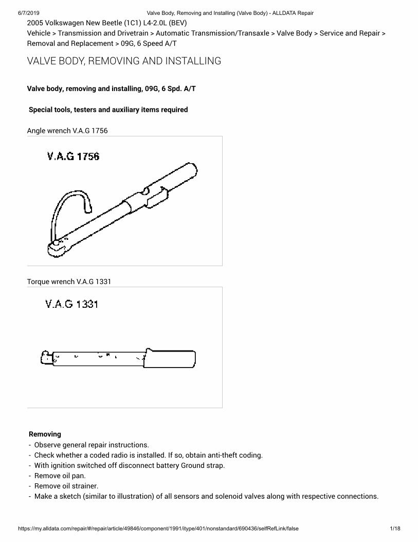
Removing - Observe general repair instructions. - Check whether a coded radio is installed. If so, obtain anti-theft coding. - With ignition switched off disconnect battery Ground strap. - Remove oil pan. - Remove oil strainer. - Make a sketch (similar to illustration) of all sensors and solenoid valves along with respective connections.
6/7/2019 Valve Body, Removing and Installing (Valve Body) - ALLDATA Repair
https://my.alldata.com/repair/#/repair/article/49846/component/1991/itype/401/nonstandard/690436/selfRefLink/false 2/18
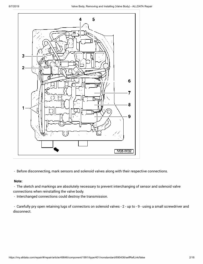
- Before disconnecting, mark sensors and solenoid valves along with their respective connections.
Note: - The sketch and markings are absolutely necessary to prevent interchanging of sensor and solenoid valveconnections when reinstalling the valve body. - Interchanged connections could destroy the transmission.
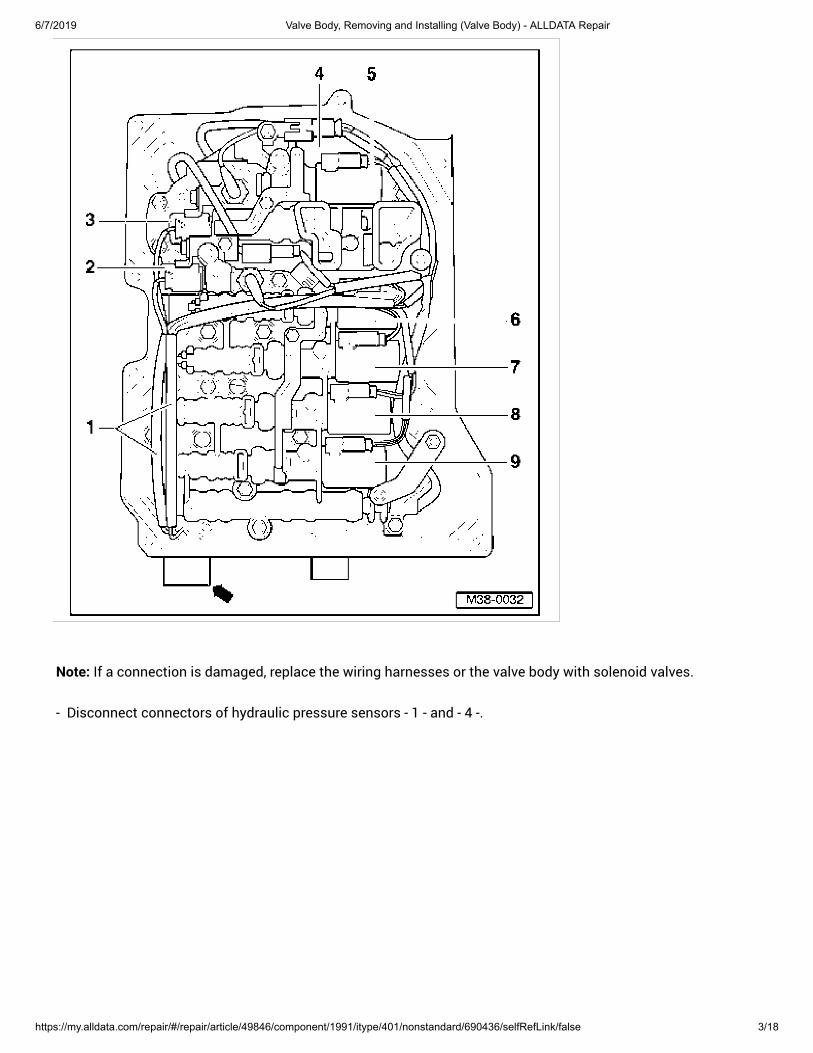
- Carefully pry open retaining lugs of connectors on solenoid valves - 2 - up to - 9 - using a small screwdriver anddisconnect.
6/7/2019 Valve Body, Removing and Installing (Valve Body) - ALLDATA Repair
https://my.alldata.com/repair/#/repair/article/49846/component/1991/itype/401/nonstandard/690436/selfRefLink/false 3/18
Note: If a connection is damaged, replace the wiring harnesses or the valve body with solenoid valves.
- Disconnect connectors of hydraulic pressure sensors - 1 - and - 4 -.
6/7/2019 Valve Body, Removing and Installing (Valve Body) - ALLDATA Repair
https://my.alldata.com/repair/#/repair/article/49846/component/1991/itype/401/nonstandard/690436/selfRefLink/false 4/18
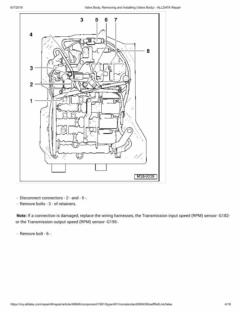
- Disconnect connectors - 2 - and - 5 -. - Remove bolts - 3 - of retainers.
Note: If a connection is damaged, replace the wiring harnesses, the Transmission input speed (RPM) sensor -G182-
or the Transmission output speed (RPM) sensor -G195-.
- Remove bolt - 6 -.
6/7/2019 Valve Body, Removing and Installing (Valve Body) - ALLDATA Repair
https://my.alldata.com/repair/#/repair/article/49846/component/1991/itype/401/nonstandard/690436/selfRefLink/false 5/18
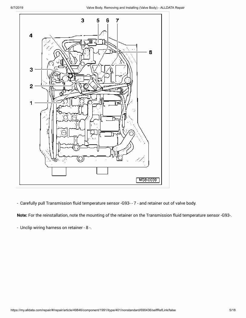
- Carefully pull Transmission fluid temperature sensor -G93- - 7 - and retainer out of valve body.
Note: For the reinstallation, note the mounting of the retainer on the Transmission fluid temperature sensor -G93-.
- Unclip wiring harness on retainer - 8 -.
6/7/2019 Valve Body, Removing and Installing (Valve Body) - ALLDATA Repair
https://my.alldata.com/repair/#/repair/article/49846/component/1991/itype/401/nonstandard/690436/selfRefLink/false 6/18
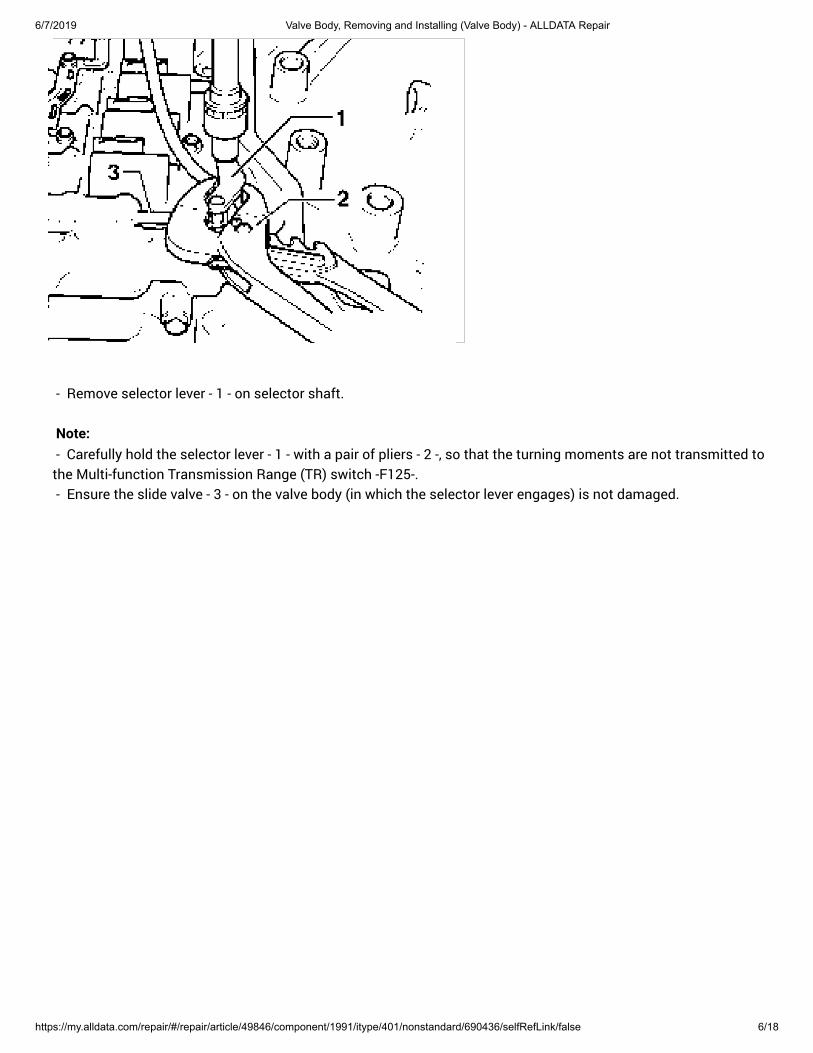
- Remove selector lever - 1 - on selector shaft.
Note: - Carefully hold the selector lever - 1 - with a pair of pliers - 2 -, so that the turning moments are not transmitted tothe Multi-function Transmission Range (TR) switch -F125-. - Ensure the slide valve - 3 - on the valve body (in which the selector lever engages) is not damaged.
6/7/2019 Valve Body, Removing and Installing (Valve Body) - ALLDATA Repair
https://my.alldata.com/repair/#/repair/article/49846/component/1991/itype/401/nonstandard/690436/selfRefLink/false 7/18
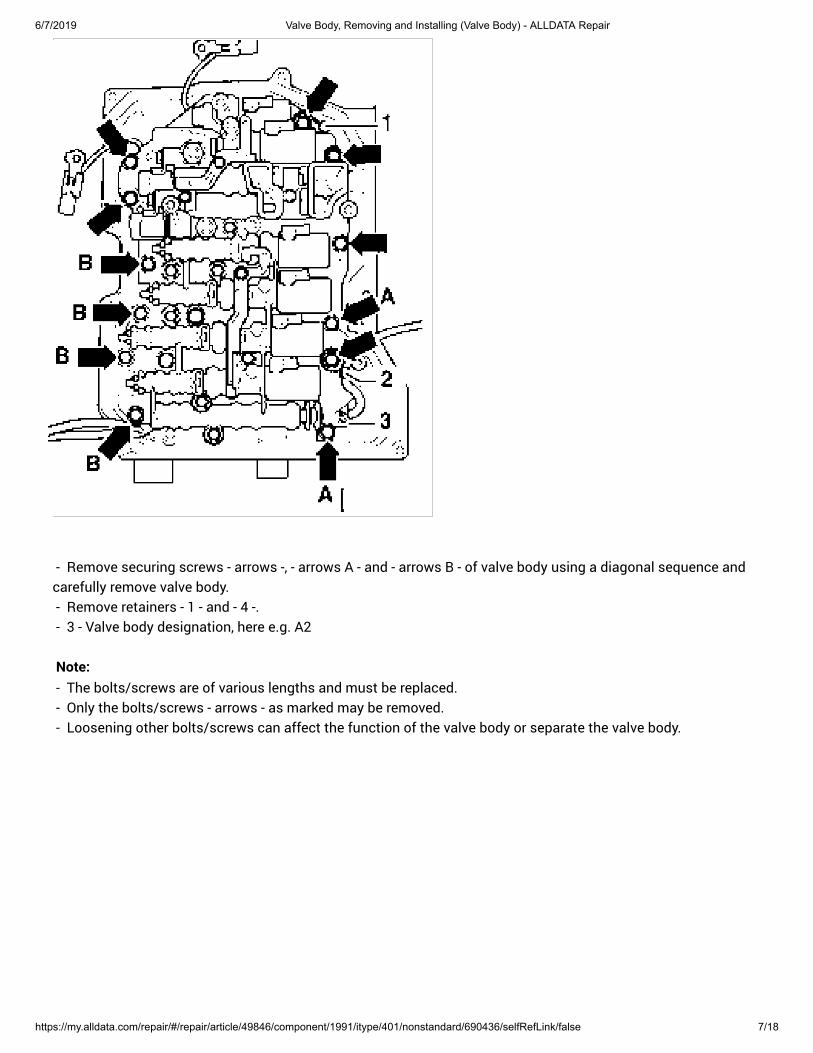
- Remove securing screws - arrows -, - arrows A - and - arrows B - of valve body using a diagonal sequence andcarefully remove valve body. - Remove retainers - 1 - and - 4 -. - 3 - Valve body designation, here e.g. A2
Note: - The bolts/screws are of various lengths and must be replaced. - Only the bolts/screws - arrows - as marked may be removed. - Loosening other bolts/screws can affect the function of the valve body or separate the valve body.
6/7/2019 Valve Body, Removing and Installing (Valve Body) - ALLDATA Repair
https://my.alldata.com/repair/#/repair/article/49846/component/1991/itype/401/nonstandard/690436/selfRefLink/false 8/18
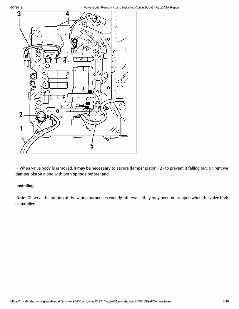
- When valve body is removed, it may be necessary to secure damper piston - 2 - to prevent it falling out. Or, removedamper piston along with both springs beforehand.
Installing
Note: Observe the routing of the wiring harnesses exactly, otherwise they may become trapped when the valve body
is installed.
6/7/2019 Valve Body, Removing and Installing (Valve Body) - ALLDATA Repair
https://my.alldata.com/repair/#/repair/article/49846/component/1991/itype/401/nonstandard/690436/selfRefLink/false 9/18
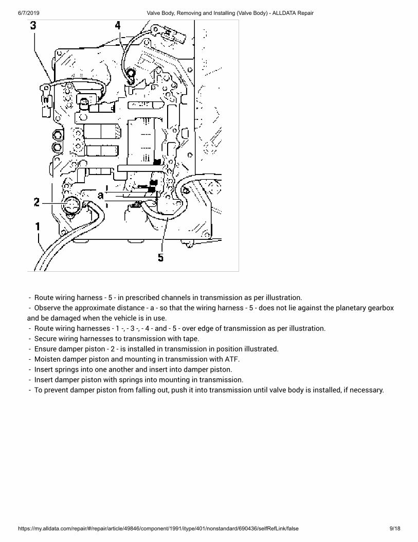
- Route wiring harness - 5 - in prescribed channels in transmission as per illustration. - Observe the approximate distance - a - so that the wiring harness - 5 - does not lie against the planetary gearboxand be damaged when the vehicle is in use. - Route wiring harnesses - 1 -, - 3 -, - 4 - and - 5 - over edge of transmission as per illustration. - Secure wiring harnesses to transmission with tape. - Ensure damper piston - 2 - is installed in transmission in position illustrated. - Moisten damper piston and mounting in transmission with ATF. - Insert springs into one another and insert into damper piston. - Insert damper piston with springs into mounting in transmission. - To prevent damper piston from falling out, push it into transmission until valve body is installed, if necessary.
6/7/2019 Valve Body, Removing and Installing (Valve Body) - ALLDATA Repair
https://my.alldata.com/repair/#/repair/article/49846/component/1991/itype/401/nonstandard/690436/selfRefLink/false 10/18
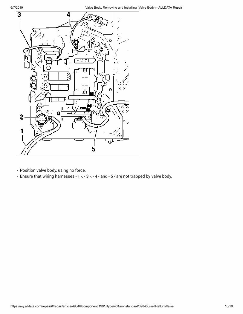
- Position valve body, using no force. - Ensure that wiring harnesses - 1 -, - 3 -, - 4 - and - 5 - are not trapped by valve body.
6/7/2019 Valve Body, Removing and Installing (Valve Body) - ALLDATA Repair
https://my.alldata.com/repair/#/repair/article/49846/component/1991/itype/401/nonstandard/690436/selfRefLink/false 11/18
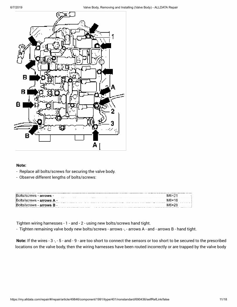
Note: - Replace all bolts/screws for securing the valve body. - Observe different lengths of bolts/screws:
Tighten wiring harnesses - 1 - and - 2 - using new bolts/screws hand tight. - Tighten remaining valve body new bolts/screws - arrows -, - arrows A - and - arrows B - hand tight.
Note: If the wires - 3 -, - 5 - and - 9 - are too short to connect the sensors or too short to be secured to the prescribed
locations on the valve body, then the wiring harnesses have been routed incorrectly or are trapped by the valve body.
6/7/2019 Valve Body, Removing and Installing (Valve Body) - ALLDATA Repair
https://my.alldata.com/repair/#/repair/article/49846/component/1991/itype/401/nonstandard/690436/selfRefLink/false 12/18
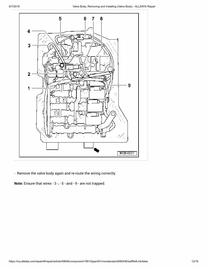
- Remove the valve body again and re-route the wiring correctly.
Note: Ensure that wires - 3 -, - 5 - and - 9 - are not trapped.
6/7/2019 Valve Body, Removing and Installing (Valve Body) - ALLDATA Repair
https://my.alldata.com/repair/#/repair/article/49846/component/1991/itype/401/nonstandard/690436/selfRefLink/false 13/18
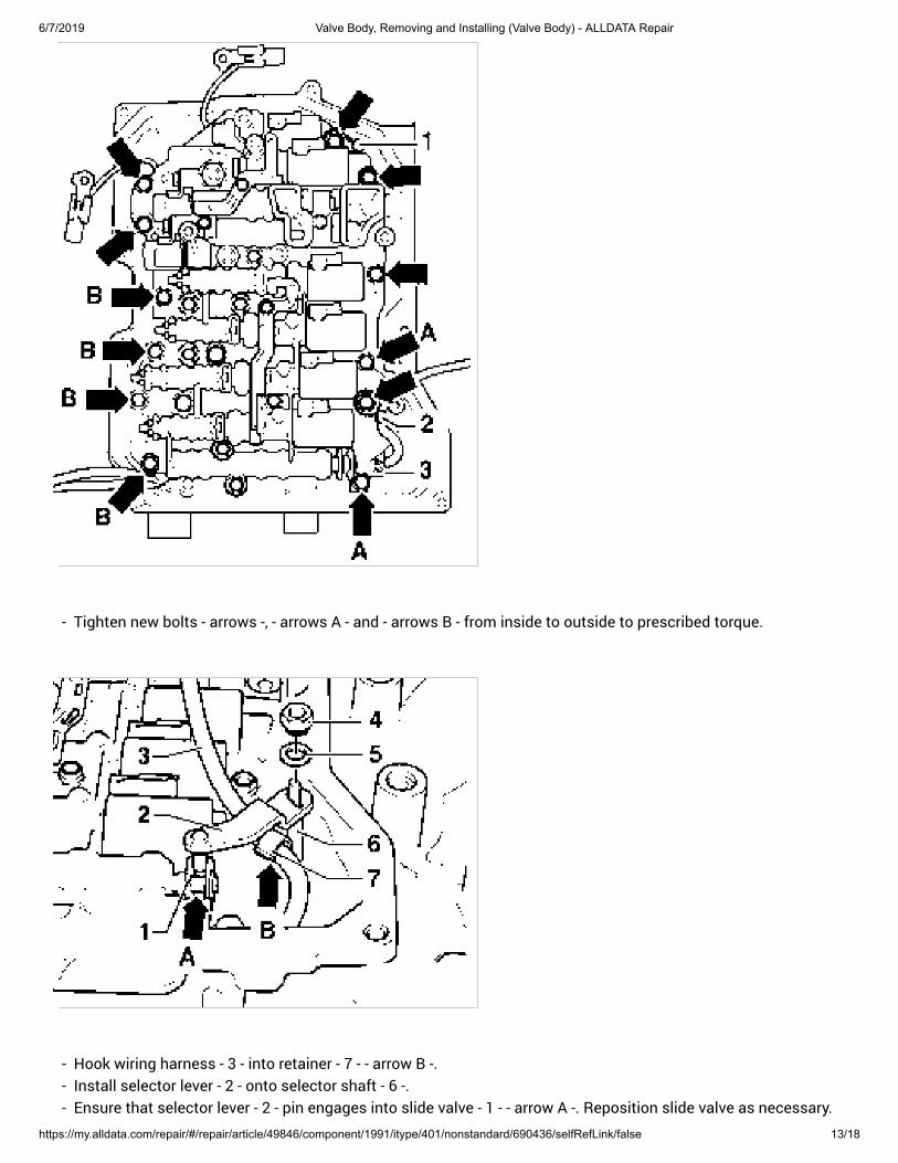
- Tighten new bolts - arrows -, - arrows A - and - arrows B - from inside to outside to prescribed torque.
- Hook wiring harness - 3 - into retainer - 7 - - arrow B -. - Install selector lever - 2 - onto selector shaft - 6 -. - Ensure that selector lever - 2 - pin engages into slide valve - 1 - - arrow A -. Reposition slide valve as necessary.
6/7/2019 Valve Body, Removing and Installing (Valve Body) - ALLDATA Repair
https://my.alldata.com/repair/#/repair/article/49846/component/1991/itype/401/nonstandard/690436/selfRefLink/false 14/18
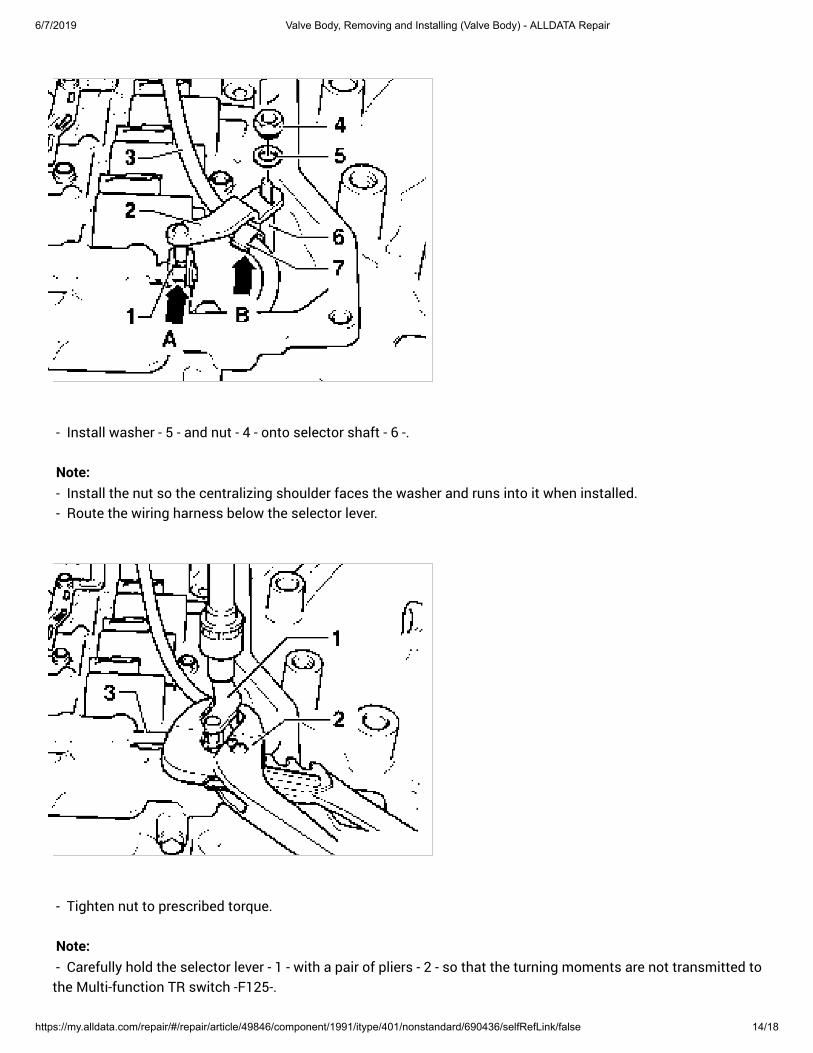
- Install washer - 5 - and nut - 4 - onto selector shaft - 6 -.
Note: - Install the nut so the centralizing shoulder faces the washer and runs into it when installed. - Route the wiring harness below the selector lever.
- Tighten nut to prescribed torque.
Note: - Carefully hold the selector lever - 1 - with a pair of pliers - 2 - so that the turning moments are not transmitted tothe Multi-function TR switch -F125-.
6/7/2019 Valve Body, Removing and Installing (Valve Body) - ALLDATA Repair
https://my.alldata.com/repair/#/repair/article/49846/component/1991/itype/401/nonstandard/690436/selfRefLink/false 15/18
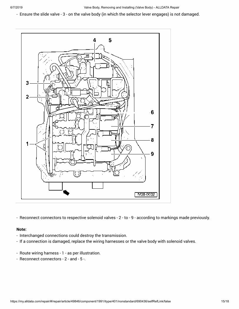
- Ensure the slide valve - 3 - on the valve body (in which the selector lever engages) is not damaged.
- Reconnect connectors to respective solenoid valves - 2 - to - 9 - according to markings made previously.
Note: - Interchanged connections could destroy the transmission. - If a connection is damaged, replace the wiring harnesses or the valve body with solenoid valves.
- Route wiring harness - 1 - as per illustration. - Reconnect connectors - 2 - and - 5 -.
6/7/2019 Valve Body, Removing and Installing (Valve Body) - ALLDATA Repair
https://my.alldata.com/repair/#/repair/article/49846/component/1991/itype/401/nonstandard/690436/selfRefLink/false 16/18
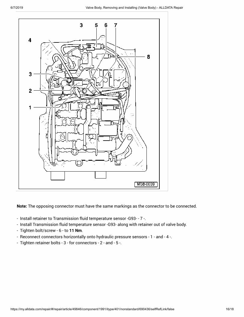
Note: The opposing connector must have the same markings as the connector to be connected.
- Install retainer to Transmission fluid temperature sensor -G93- - 7 -. - Install Transmission fluid temperature sensor -G93- along with retainer out of valve body. - Tighten bolt/screw - 6 - to 11 Nm.
- Reconnect connectors horizontally onto hydraulic pressure sensors - 1 - and - 4 -. - Tighten retainer bolts - 3 - for connectors - 2 - and - 5 -.
6/7/2019 Valve Body, Removing and Installing (Valve Body) - ALLDATA Repair
https://my.alldata.com/repair/#/repair/article/49846/component/1991/itype/401/nonstandard/690436/selfRefLink/false 17/18
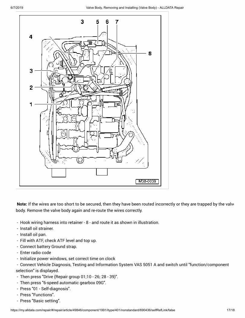
Note: If the wires are too short to be secured, then they have been routed incorrectly or they are trapped by the valve
body. Remove the valve body again and re-route the wires correctly.
- Hook wiring harness into retainer - 8 - and route it as shown in illustration. - Install oil strainer. - Install oil pan. - Fill with ATF, check ATF level and top up. - Connect battery Ground strap. - Enter radio code - Initialize power windows, set correct time on clock - Connect Vehicle Diagnosis, Testing and Information System VAS 5051 A and switch until "function/componentselection" is displayed. - Then press "Drive (Repair group 01;10 - 26; 28 - 39)". - Then press "6-speed automatic gearbox 09G". - Press "01 - Self-diagnosis". - Press "Functions". - Press "Basic setting".
6/7/2019 Valve Body, Removing and Installing (Valve Body) - ALLDATA Repair
https://my.alldata.com/repair/#/repair/article/49846/component/1991/itype/401/nonstandard/690436/selfRefLink/false 18/18