Embed Size (px)
Citation preview

Manual No. BV-OM1-6
Val-Matic® Rubber-Seated Ball Valve
Operation, Maintenance and Installation Manual
INTRODUCTION ....................................... 2 RECEIVING AND STORAGE .................... 2 DESCRIPTION OF OPERATION .............. 2 VALVE CONSTRUCTION ......................... 3 INSTALLATION REQUIREMENTS ........... 4 MAINTENANCE ......................................... 8 TROUBLESHOOTING ............................. 10 DISASSEMBLY ....................................... 10 REASSEMBLY ........................................ 11 PARTS & SERVICE ................................. 12 WARRANTY ............................................ 12
VALVE AND MANUFACTURING CORP.
905 Rivers ide Dr. ● Elmhurst , IL 60126 Phone (630) 941-7600 ● Fax (630) 941-8042 www.valmatic.com
2
CAUTION Do not use valve for line testing at pressures higher than nameplate rating or leakage and damage to valve may occur.
VAL-MATIC'S 4"-54" SERIES 4000 BALL VALVE OPERATION, MAINTENANCE AND INSTALLATION INTRODUCTION The Series 4000 Ball Valve has been designed to provide long trouble-free operation. This manual will provide you with the information to properly install and maintain the valve to ensure a long service life. The valve is a resilient seated, quarter-turn valve capable of handling water and wastewater. The Size, Cold Working Pressure (CWP), and Model No. are stamped on the nameplate for reference.
The "Cold Working Pressure" is the non-shock pressure rating of the valve at 150oF. On pump discharge service, the valve is intended for flow toward the seat end of the valve. The “Seat End” is marked on the nameplate for single-seated valves. This allows seat adjustment while the valve is holding system pressure. Double seated valves can be installed with flow and pressure in either direction. RECEIVING AND STORAGE Inspect valves upon receipt for damage in shipment. Unload all valves carefully to the ground without dropping. Do not lift valves with slings or chains around the actuator or through the seat area. Lift valve with straps or hooks in the lifting eyes integrally cast on the body flanges. Extra care must be taken when handling electric motor and cylinder actuated valves. Valves should remain crated, clean and dry until installed to prevent weather related damage. The valve is shipped slightly open to maintain the resilient seat in the un-loaded condition. For long-term storage greater than six months, indoor storage is recommended. The valve flange covers must remain in place, the valve must remain slightly open (3-5 degrees), and the rubber surfaces of the ball should be coated with a thin film of FDA approved grease such as Dow Corning # 7. Do not expose the resilient seat to sunlight or ozone for any extended period.
DESCRIPTION OF OPERATION
As shown in Figure 1, the valve consists of a two-piece body, cast ball, and shafts that rotate in shaft bearings. The ball is centered in the body with a thrust bearing assembly. The resilient seats provide drop-tight shutoff.
FIGURE 1. RESILIENT-SEATED BALL VALVE The ball is rigidly attached to the shaft with taper pins. The actuator rotates the valve shaft and ball through 90 degrees of operation. The ball can rotate through the seat, but is factory set to stop in the center of the seat to provide tight shut off. Additional torque on the actuator when against the closed stop of the actuator will not provide tighter shut off. The valve seat is easily adjustable or replaceable should wear or damage occur over time. The valve is operated with a traveling nut manual actuator; see Figure 3, which requires multi-turn input on a handwheel or nut. The valve can also be automated with power actuators such as an electric motor or hydraulic cylinder.
3
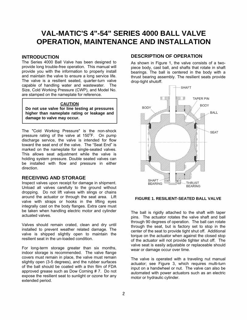
Table 1. Standard Valve Parts List Item Description Material 1 Body Gray or Ductile Iron 2 Body Seat Stainless Steel 3 Ball Gray or Ductile Iron 4 Shaft Stainless Steel 5 Sleeve Bearing* Teflon/Fiberglass 6 Resilient Seat* Resilient 7 Seat Retaining Ring Stainless Steel 8 Ret. Ring Screws* Stainless Steel 9 Taper Pin Stainless Steel 10 Grit Seal * Molythane 11 Taper Pin Bolt Stainless Steel 12 Taper Pin Washer Stainless Steel 13 Packing* Buna-N 14 Key Carbon Steel 15 Thrust Bearing Cap Ductile Iron 16 Cap Screws Carbon Steel, Plated 17 Thrust Brg. Shims Brass 18 Thrust Bearing Bronze 19 Body Bolts Carbon Steel, Plated 20 Cap O-ring Resilient 24 Body O-ring Resilient
*Recommended Spare Part
VALVE CONSTRUCTION The standard Series 4000 Ball Valve is constructed of rugged cast iron with stainless steel shafts and resilient seat. See the specific Materials List submitted for the order if other than standard cast iron construction. The details of construction are illustrated in Figure 2. The body (1) is available with Class 150# or Class 300# flanged ends for connection to the pipeline. The body is equipped with a stainless steel seat (2). The 1/4 turn ball (3) is guided by a stainless steel shaft (4) which rotates in non-metallic bearings (5) fixed in the body. Leak-tight closure is made when the resilient seat (6) located on the ball. If the valve is labeled as a “Single” seat valve, the seat will be on the right end and this is the end that is installed toward the pump.
FIGURE 2. BALL VALVE PARTS LIST
FIGURE 3. VALVE WITH MANUAL ACTUATOR

4
INSTALLATION REQUIREMENTS Ball valves are a significant component of any water pumping system or wastewater system. Valve failure caused by faulty installation, improper operation, or maintenance in these systems could result in damage, down time, and costly repairs. In buried or underground installations, problems or malfunctions can result in extensive, costly excavation to correct or eliminate the problem. Many problems with ball valves can be traced to improper installation, operation, or maintenance procedures. OPERATING PARAMETERS: The valve nameplate lists the maximum pressures and flow rates within which the valve is intended to operate. If the system parameters exceed these values, contact the factory for assistance. VALVE TYPE: The nameplate will indicate whether the valve is a “Single” or “Double” seated valve. Flow direction as discussed below, is important for single seat valves. SHAFT ORIENTATION: It is common to install the valve with the shaft horizontal. This places the actuator on the side of the pipeline providing good access to the handwheel, nut, or cylinder actuator controls. However, the standard valve is designed to be installed with the shaft in any orientation. BURIED SERVICE: The valve should be installed with the shaft horizontal and the actuator nut directed upwards. The valve box or extension pipe should be installed so that the actuator nut and extension stem turn freely. SEAT ORIENTATION FOR PIPELINE SERVICE: If the valve is furnished with a single seat, the normal flow direction is towards the seat end of the valve. When the flow stops, the return pressure will be held by the closed ball and the seat bolts (8) can be adjusted to provide tight shut off should the seat be worn or damaged. The nameplate is located on the seat end valve flange. If the valve is furnished with double seats, flow direction is not important. SEAT ORIENTATION FOR PUMP DISCHARGE SERVICE: On all horizontal pump discharge applications (Figure 4), the seat end should be towards the pump to allow seat adjustment with system pressure against the ball (Figure 4). If the valve is furnished with double seats, flow direction is not important.
VALVE SUPPORT: The valve is designed with integrally cast pads for lifting and supporting the weight of the valve on a suitable hanger, support, or concrete pier. The support system should be designed to support the weight of the valve and not the axial motion of the piping system, see Figure 5. FLANGED ENDS: AWWA Class 150 flanged valves should be mated to ANSI Class 125# flat-faced flanges equipped with resilient gaskets. When ring gaskets are used, the bolt material shall be ASTM A307 Grade B or SAE Grade 2 Carbon Steel. Higher strength bolts may only be used with full-face gaskets.
FIGURE 4. Flow Direction for Pump Discharge
FIGURE 5. Support Valve Weight
FIELD TESTING When rubber-seated ball valves are used to isolate sections of a line for testing, it is important to realize that these valves are designed or factory adjusted to hold rated pressure only. If single seated, they hold pressure in one direction only. Also, test pressures
NOTE: Adjust and test valve prior to backfill.

5
above valve rated pressure may cause leakage past the rubber seat and damage to the valve. In order to prevent time lost searching for leaks, where feasible, it is recommended that excavations for buried valves not be backfilled until after pressure tests have been made. Seat leakage can occur from foreign material in the line. If this occurs, open the valve 5°–10° to obtain high-velocity flushing action, and then close. Repeat several times to clear the seats for tight shutoff. Seat leakage can result from a rotational shift in position of the ball with relation to the body seat. Readjust the closed end stop in accordance with these instructions. OPERATION Do not permit the use or operation of any valve at pressures above the rated pressure of the valve. Do not exceed 300 ft-lb input torque on worm gears or 450 ft-lb input torque on traveling-nut actuators with wrench nuts. Do not exceed 200 lb rim pull for handwheels or chainwheels. If portable auxiliary actuators are used, size the actuator or use a torque-limiting device to prevent application of excessive torque. If an oversize actuator with no means of limiting torque is used, stop the actuator before the valve is fully opened or closed against stops and complete the operation manually. Be sure to check the actuator directional switch against the direction indicated on wrench nut, handwheel, or records before applying opening or closing torque. If a valve is stuck in some intermediate position between open and closed, check first for jamming in the actuator. If nothing is found, the interference is inside the valve. In this case, do not attempt to force the valve open or closed, because excessive torque in this position can severely damage internal parts. Operation of the valve rapidly may cause pressure surges and damage to the valve and the pipeline, especially on long pipelines. Do not bypass power actuator speed control devices. When using a power tool to operate a manual actuator, maintain an input shaft speed typical of manual operation. INSPECTION PRIOR TO INSTALLATION Make sure flange faces, joint sealing surfaces, body seats, and ball resilient seats are clean. Check the bolting attaching the actuator to the valve for loosening in transit and handling. If loose, tighten firmly. Open and close the valve to make sure it operates properly and that stops or limit switches are correctly set so that the valve seats fully. Close valve before installing to prevent damage to seating surfaces.
INSTALLING 1. Handle valves carefully using lifting lugs provided
when positioning, avoiding contact or impact with other equipment, vault walls, or trench walls.
2. Valves are to be installed in accordance with
these instructions. To maintain the integrity of the valve, it is important to avoid subjecting the valve to pipe loads that could drive the valve out of round. The valve is designed for vertical support from a concrete support or similar structure, see Figure 5. The valve support pads should not be anchored to the concrete support but instead rest on a slide plate to avoid axial pipe loads. Piping to and from the valve should be adequately supported and controlled. Piping design requirements should include allowable flange loadings, thermal expansion and contraction, and differential settlement.
3. Foreign material in a ball valve can damage the
rubber seat when valves are operated. Be sure valve interiors and adjacent piping are cleaned of foreign material prior to making up valve to pipe joint connection.
4. Where practical, valves in buried installations
should be located in vaults. Buried valves installed with valve boxes shall be installed so that the valve box does not transmit shock or stress to the valve actuator as a result of shifting soil or traffic load.
5. Prepare pipe ends and install valves in
accordance with the pipe manufacturer’s instructions for the joint used. Do not deflect pipe-valve joint. Do not use a valve as a jack to pull pipe into alignment. The installation procedure should minimize the bending of the valve/pipe connection with pipe loading.
6. For horizontal pipelines, the valve and adjacent
piping must be supported and aligned to prevent cantilevered stress on the valve. Lower valve into line using slings or hooks in the integrally cast body lifting lugs. Lubricate the flange bolts or studs and insert them around the flange. Lightly turn bolts until gaps are eliminated.
7. The torquing of the bolts should then be done in
graduated steps using the cross-over tightening method. Recommended lubricated torques for use with resilient gaskets (75 durometer) is given in Tables 2 and 3. Do not exceed bolt rating or crush gasket more than 50 percent of its thickness.

6
8. Make sure the valve ball, when opened, will not
contact adjacent valves. 9. Buried valves installed with valve boxes shall be
installed so that the valve box does not transmit shock or stress to the valve actuator as a result of shifting soil or traffic load.
10. When valves are installed in vaults; the vault
design shall provide space for removal of the valve-actuator assembly for purposes of repair and for access to adjust the thrust bearing assembly. The possibility of groundwater or surface water entering the valve and the disposal of the water should be considered. The valve-operating nut should be accessible from the top opening of the vault with a tee wrench.
11. Ball valves are self-contained devices that may
not function properly or remain tight if subjected to external forces. If a valve is rigidly installed in a pipeline using flanged joints, the whole assembly of pipe and valves can be stressed by temperature changes, settlement, and exceptional surface loads.
12. When buried, the valve should be bolted to
flanges of the adjacent piping with no other rigid support provided under or around the valve body. In no case shall the valve body be supported directly by a rigid saddle or other structure. In this condition, the valve becomes an anchor or a support for the piping system and must transmit piping loads.
Table 2. 150# Flange Bolt Torques
Valve Bolt Recom Max Size Dia Torque Torque (in) (in) (ft-lbs) (ft-lbs) 4 5/8 30 150 6 3/4 30 150 8 3/4 40 150 10 7/8 45 200 12 7/8 65 200 14 1 80 300 16 1 90 300 18 1 1/8 100 425 20 1 1/8 120 425 24 1 1/4 150 600 30 1 1/4 175 600 36 1 1/2 175 1000 42 1 1/2 200 1000 48 1 1/2 250 1000 54 1-3/4 300 1500
CAUTION The use of raised-face flanges or excessive bolt torque may damage valve flanges.
Table 3. 300# Flange Bolt Torques
Valve Bolt Recom Max Size Dia Torque Torque (in) (in) (ft-lbs) (ft-lbs) 4 3/4 30 150 6 3/4 30 150 8 7/8 50 200 10 1 75 300 12 1 1/8 100 425 14 1 1/8 100 425 16 1 1/4 150 600 18 1 1/4 150 600 20 1 1/4 200 600 24 1 1/2 300 1000 30 1 3/4 400 1500 36 2 500 2000 42 2 600 2000 48 2 700 2000 54 1-3/4 750 1500
CAUTION The use of raised-face flanges or excessive bolt torque may damage valve flanges.
7
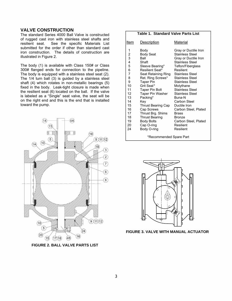
INSTALLATION (Cont'd) GEAR OPERATED VALVES: Ball Valves are provided with traveling-nut actuators. A traveling nut actuator (Figure 6) has a threaded rod (14) that drives a nut (12) from one end of the housing (1) to another. The traveling nut in turn drives a slotted lever through 90 degrees of rotation. Traveling nut actuators provide slower rotation and greater torque multiplication at the ends of travel. A bevel gear mounted on the input side of the actuator provides additional torque on larger units (Figure 7).
FIGURE 6. LS1A-LS4A ACTUATOR
These actuators are self-locking and multiply the turning force on the handwheel or nut so that valves can be operated with ease. A clamp-on chainwheel kit can also be used for installations high above the floor. An indicator on the top of the actuator housing indicates the position of the valve ball. The handwheel or nut must be rotated through 15-579 turns (depending on model) to open or close the ball valve. The direction of rotation to open the valve is indicated on the 2" square actuator nut and handwheel. The standard direction of rotation is open left or counter-clockwise to open. Nuts with opposite rotation (open right) will be painted red to indicate their special rotation. GEAR ACTUATOR ADJUSTMENT: The standard actuator is provided with factory-set open and closed position stops to properly center the closed ball seal in the body seat. No field adjustment is necessary.
FIGURE 7. LS5A-LS7A ACTUATOR
CAUTION Fill LSA Actuators with grease prior to mounting electric motor actuators.

8
VALVE SEAT ADJUSTMENT: If the valve is found to leak in service, the rubber seat can be adjusted. With the valve in the closed position, tighten the three seat bolts in the area of the leak 1/4 turn at a time until the leak stops. The factory settings for the seat bolts are given in Table 4 for reference in case the valve can not be tested while under pressure. These torques are for use with the ball in the closed position. Torques greater than 150% of these will make the valve difficult to operate. MAINTENANCE The Series 4000 Rubber-Seated Ball Valve requires no scheduled lubrication or maintenance other than regular exercising. The exercising is achieved by fully opening and closing the valve to verify smooth operation. If operation is difficult, it may be necessary to flush sediment from the valve by opening and closing the valve several times under flowing conditions or checking the lubricant in the gear actuator. The recommended interval for exercising is every six
months or annually if the valve is regularly operated. Over the life of the valve, inspection and some regular adjustments may be needed as given below. PACKING ADJUSTMENT: The shaft is equipped with a set of V-shaped packing which is factory-set for drop-tight service. The packing is pressure assisted and does not normally require adjustment. Should leakage occur, the packing can be replaced. PACKING REPLACEMENT: To replace the packing, it is recommended that the line be drained and the actuator removed. The valve can remain in the line. 1. To replace the packing, first open the valve and
drain the line.
2. Close the valve to hold the ball in position. For power actuators, turn off and lock out electrical and hydraulic supplies before proceeding.
3. Remove small round cover on actuator to expose
shaft and key. 4. Remove actuator mounting bolts and adapter
plate or packing retainer plate. 5. Lift actuator and plates from valve taking care not
to lose square key. 6. Remove old packing (13) with packing hook. 7. Lubricate new packing with FDA grease and set
in place one ring at a time taking care not to bend over the lips of the packing rings.
8. Reinstall actuator mounting plates. Clean off all
grease from the surfaces of the actuator mounting surfaces.
9. With valve in the closed position, place actuator
over valve and reinsert key (14). 10. Finally, with valve closed, install cover on
actuator indicating “Closed". TRAVELING NUT ACTUATOR MAINTENANCE: A typical traveling nut actuator is shown in Figures 5 and 6 and consists of a threaded nut (12) which travels back and forth on a threaded stem (14). The stem is lubricated with EP2 grease in a cast iron housing (1). The nut, in turn, drives a slotted lever (4) through 90 degrees of travel. The lever (4) drives the valve shaft with a square key. The rotation of the shaft is displayed by the top indicator (19). The full open and closed positions are controlled by the stop bolts (7). The stop bolts can be adjusted by loosening the lock nut and rotating the stop bolt ½ turn. The gear box is factory lubricated and sealed. No regular maintenance is required. If difficult operation is observed, the cover can be removed and the unit inspected for wear. All moving parts should be coated with grease. The grease should have an even and smooth consistency. If needed, coat all moving parts with an EP-2 grease such as Mobil Mobilux EP2. Buried units should be packed 90% with grease.
WARNING Drain Line and close valve before removing actuator or valve may rotate suddenly causing bodily injury or damage to property.
Table 4. Seat Bolt Torques
Sizes Class 150 Class 300 4”-24” 5-10 10-15 ft-lbs 30”-54” 5-10 10-15 ft-lbs
9
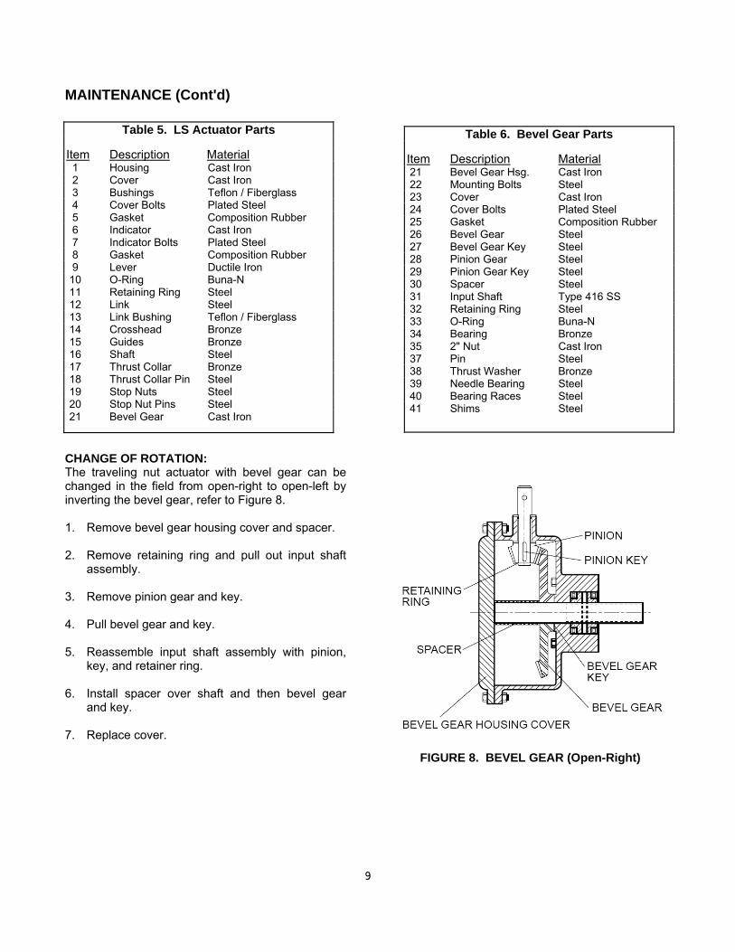
Table 6. Bevel Gear Parts Item Description Material 21 Bevel Gear Hsg. Cast Iron 22 Mounting Bolts Steel 23 Cover Cast Iron 24 Cover Bolts Plated Steel 25 Gasket Composition Rubber 26 Bevel Gear Steel 27 Bevel Gear Key Steel 28 Pinion Gear Steel 29 Pinion Gear Key Steel 30 Spacer Steel 31 Input Shaft Type 416 SS 32 Retaining Ring Steel 33 O-Ring Buna-N 34 Bearing Bronze 35 2" Nut Cast Iron 37 Pin Steel 38 Thrust Washer Bronze 39 Needle Bearing Steel 40 Bearing Races Steel 41 Shims Steel
MAINTENANCE (Cont'd) CHANGE OF ROTATION: The traveling nut actuator with bevel gear can be changed in the field from open-right to open-left by inverting the bevel gear, refer to Figure 8. 1. Remove bevel gear housing cover and spacer. 2. Remove retaining ring and pull out input shaft
assembly. 3. Remove pinion gear and key. 4. Pull bevel gear and key. 5. Reassemble input shaft assembly with pinion,
key, and retainer ring. 6. Install spacer over shaft and then bevel gear
and key. 7. Replace cover.
FIGURE 8. BEVEL GEAR (Open-Right)
Table 5. LS Actuator Parts Item Description Material 1 Housing Cast Iron 2 Cover Cast Iron 3 Bushings Teflon / Fiberglass 4 Cover Bolts Plated Steel 5 Gasket Composition Rubber 6 Indicator Cast Iron 7 Indicator Bolts Plated Steel 8 Gasket Composition Rubber 9 Lever Ductile Iron 10 O-Ring Buna-N 11 Retaining Ring Steel 12 Link Steel 13 Link Bushing Teflon / Fiberglass 14 Crosshead Bronze 15 Guides Bronze 16 Shaft Steel 17 Thrust Collar Bronze 18 Thrust Collar Pin Steel 19 Stop Nuts Steel 20 Stop Nut Pins Steel 21 Bevel Gear Cast Iron

10
TROUBLESHOOTING Several problems and solutions are presented below to assist you in troubleshooting the valve assembly in an efficient manner. Leakage at Valve Shaft: Replace packing. Leakage at Flanges: Tighten flange bolts, replace
gasket. Valve Leaks when Closed: Flush debris from seat
by cycling valve. Adjust actuator closed stop. Inspect seat for damage and adjust seat bolts 1/4 turn at a time.
If the valve continues to leak after adjustment, check for the following items and make the corrections. 1. Verify that there is no damage to the rubber
seat. Replace if torn or damaged. 2. Check that the metal seat in the body is clean
and free of scale and scratches. 3. Check that the actuator is fully closed and the
seal is centered in the body seat. Adjustment to the actuator stop nuts or bolts may be necessary.
4. Verify that the test pressure is less than the cold
working pressure (CWP) shown on the valve nameplate.
Hard to Open: Flush line of debris. Check grease
in actuator. Check interior of valve for deposits or debris. On buried valves, check alignment of operating stem and nut.
Leaking Oil: Tighten actuator cover bolts. If leak
persists, remove actuator cover, inspect grease, and replace actuator gasket with liquid gasket material such as Permatex Ultra-Blue RTV..
Noisy Operation: Flow noise is normal. Loud flow
noise similar to hammering may be cavitation from dropping high pressures across valve; review application of valve. For gear actuator noise, inspect grease; add new grease if there are uncoated moving parts or grease has broken down into oil.
DISASSEMBLY Disassembly may be required to repair the valve. Work on the valve should be performed by a skilled mechanic with proper tools and a power hoist for large valves. The valve must be removed from the pipeline for disassembly. The actuator can be removed with the valve in the line (the line must be drained) or after the valve is removed from the line. Refer to Figure 2 for valve construction and parts.
1. Open valve slightly and drain the pipeline.
Close valve until disc edge just touches the seat. Valve and actuator can be removed as a unit from the pipeline.
2. Lay the longer half of the body on the floor or
saw horses. Remove the body bolts (19) and lift the short body half (1B) from the valve.
3. Remove the small cover on the actuator to
expose the shaft key. Remove the actuator mounting bolts and lift actuator from valve taking care not to lose key (24). Access to the traveling nut actuator will be under the actuator cover.
4. Remove cap (20) and thrust bearing (18), and thrust bearing shims (17). Remove the seat bolts (8) and seat retaining ring (7).
5. Remove the taper pin bolts (11) and taper pins
(9). Pull out the shaft (4). The bearings (5) should not be removed unless the teflon liner is severely worn. To remove bearings, grind a slot along its length and hammer out with a sharp chisel.
6. Remove grit seats (10) if damaged or worn. 7. Clean and inspect parts. Replace worn parts as
necessary and lubricate parts with FDA grease.
WARNING Open valve and drain line before removing actuator or the valve may suddenly open causing injury or fluid loss. Place valve in closed or slightly open position to remove from the line or damage to the disc edge may occur.
11
REASSEMBLY All parts must be cleaned and gasket surfaces should be cleaned with a stiff wire brush in the direction of the serrations or machine marks. Worn parts, gaskets and seals should be replaced during reassembly. Valve and actuator mounting bolts should be lubricated and torqued per Table 7 during reassembly. 1. Place the long body half (1A) on the floor or
bench. Insert the grit seals (10) in the bores. 2. Apply a bead of Loctite 680 on new sleeve
bearings (5) and insert into both ends of the valve body (1A) until flush with grit seal. Insert the shafts (4) through the body and grit seals (10).
3. Lower the ball (3) into place with a nylon strap
and lower the taper pins (9) into their bores so that the flat portion is toward the shaft.
4. Push the shafts until their flat portions are
aligned with the taper pin flats. Lift the taper pins with threaded rod. Apply food-grade anti-seize compound to the threads and secure with the taper pin bolts (11) and washers (12).
5. Install new seat (6), retaining ring (7) and seat
bolts (8) into ball. Apply thin film of food-grade grease such as Dow Corning #7 to rubber surface. Lightly tighten seat bolts until bolt heads touch body ring.
6. Install thrust bearing cap (15), thrust bearing
(18) and, thrust shims (17) with the o-ring seal (20).
7. Lubricate ID and OD of packing set with food-
grade grease and install in packing bore one ring at a time taking care to keep lips pointing down toward valve.
8. Install body o-ring (24) and short body half (1B)
with body bolts (19).
9. With valve fully closed, torque seat bolts in a
cross-over pattern to torque given in Table 4. 10. Insert key (24) into shaft and place actuator over
valve. Reinstall actuator mounting bolts and torque per Table 7. Install cover on actuator. Cycle valve. Apply pressure to valve and check for seat leakage. Tighten seat bolts ½ turn at a time as necessary.
11. If valve does not shut off tight, adjust the closed
position stops as described on page 6 under "Closed Position Adjustment". so that ball face is parallel to body flange within 1/8 in.
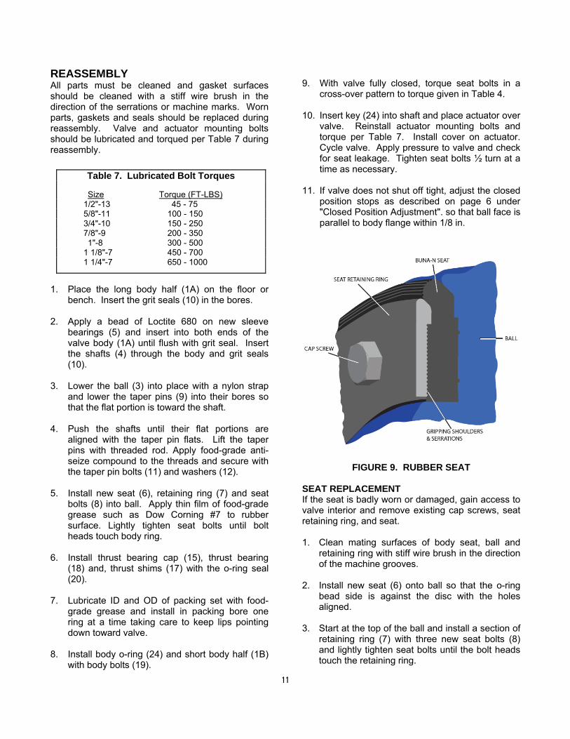
FIGURE 9. RUBBER SEAT SEAT REPLACEMENT If the seat is badly worn or damaged, gain access to valve interior and remove existing cap screws, seat retaining ring, and seat. 1. Clean mating surfaces of body seat, ball and
retaining ring with stiff wire brush in the direction of the machine grooves.
2. Install new seat (6) onto ball so that the o-ring bead side is against the disc with the holes aligned.
3. Start at the top of the ball and install a section of retaining ring (7) with three new seat bolts (8) and lightly tighten seat bolts until the bolt heads touch the retaining ring.
Table 7. Lubricated Bolt Torques
Size Torque (FT-LBS) 1/2"-13 45 - 75 5/8"-11 100 - 150 3/4"-10 150 - 250 7/8"-9 200 - 350 1"-8 300 - 500 1 1/8"-7 450 - 700 1 1/4"-7 650 - 1000

12
4. Apply a thin film of FDA silicone grease such as Dow Corning #7 to the exposed rubber surface and close the valve so that the ball is parallel with the valve flange face with in +/- 1/8 in.
5. Tighten the seat bolts in a cross-over pattern to the torque given in Table 4 using a torque wrench.
6. Cycle valve open and closed and verify that ball closes within +/- ¼ in of center. Conduct a pressure test. If necessary, tighten screws ½ turn to stop any leakage.
PARTS AND SERVICE Parts and service are available from your local representative or the factory. Make note of the valve Model No. and Working Pressure located on the valve nameplate and contact:
Val-Matic Valve and Mfg. Corp. 905 Riverside Drive Elmhurst, IL 60126 Phone: (630) 941-7600 Fax: (630) 941-8042
www.valmatic.com A sales representative will quote prices for parts or arrange for service as needed.
VALVE AND MANUFACTURING CORP.
905 Rivers ide Dr. ● Elmhurst , IL 60126 Phone (630) 941-7600 ● Fax (630) 941-8042 www.valmatic.com
LIMITED WARRANTY All products are warranted to be free of defects in material and workmanship for a period of one year from the date of shipment, subject to the limitations below. If the purchaser believes a product is defective, the purchaser shall: (a) Notify the manufacturer, state the alleged defect and request permission to return the product; (b) if permission is given, return the product with transportation prepaid. If the product is accepted for return and found to be defective, the manufacturer will, at his discretion, either repair or replace the product, f.o.b. factory, within 60 days of receipt, or refund the purchase price. Other than to repair, replace or refund as described above, purchaser agrees that manufacturer shall not be liable for any loss, costs, expenses or damages of any kind arising out of the product, its use, installation or replacement, labeling, instructions, information or technical data of any kind, description of product use, sample or model, warnings or lack of any of the foregoing. NO OTHER WARRANTIES, WRITTEN OR ORAL, EXPRESS OR IMPLIED, INCLUDING THE WARRANTIES OF FITNESS FOR A PARTICULAR PURPOSE AND MERCHANTABILITY, ARE MADE OR AUTHORIZED. NO AFFIRMATION OF FACT, PROMISE, DESCRIPTION OF PRODUCT OF USE OR SAMPLE OR MODEL SHALL CREATE ANY WARRANTY FROM MANUFACTURER, UNLESS SIGNED BY THE PRESIDENT OF THE MANUFACTURER. These products are not manufactured, sold or intended for personal, family or household purposes.


![Part Count: Omicron [OR-K-OM1]imavex.vo.llnwd.net/o18/clients/thompsonkerr/files/... · Part Count: Omicron [OR-K-OM1] Note: MDF fi nishes may vary. *-S *-B *-WD *-DWD OR-J-3 OR-J-DBL](https://img.pdfslide.us/doc/110x75/603b533251e9bb4b3a19caab/part-count-omicron-or-k-om1-part-count-omicron-or-k-om1-note-mdf-i-nishes.jpg)
![OM1 (offset management) plan [SAMPLE] · Web viewOM1 (offset management) plan [SAMPLE] Use the How to complete a OM1 (offset management) plan instruction, available on Council’s](https://img.pdfslide.us/doc/110x75/5e73692b0649395ef92d651b/om1-offset-management-plan-sample-web-view-om1-offset-management-plan-sample.jpg)


![!;]bv|u- om1 |7 u -m7 | ; ou;b]mo m|ub0 omP!;] t- omQ1 |7 uu;m; ;7 r|oequitabletourism.org/sites/default/files/2020-10/ar2018... · 2020. 10. 6. · Swadesh Darshan Scheme. Among](https://img.pdfslide.us/doc/110x75/60f966ec3ce1e940070b9c15/bvu-om1-7-u-m7-oubmo-mub0-omp-t-omq1-7-uum-7-r-2020-10.jpg)