Embed Size (px)
Citation preview
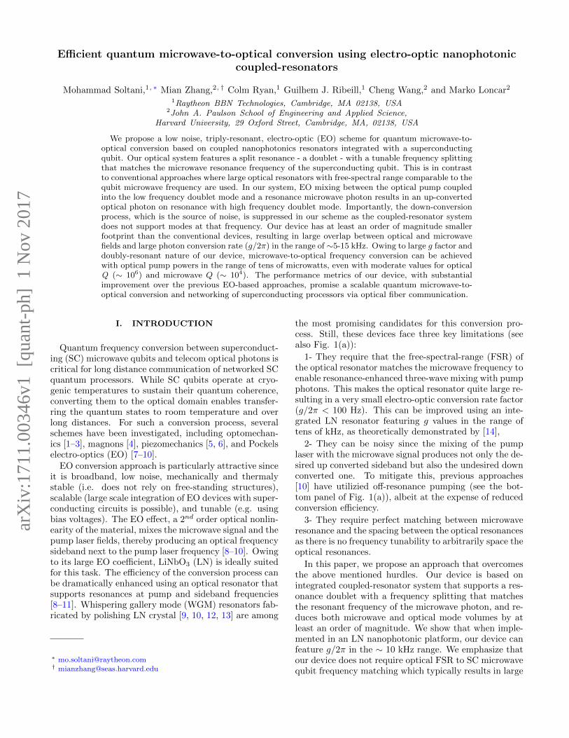
Efficient quantum microwave-to-optical conversion using electro-optic nanophotoniccoupled-resonators
Mohammad Soltani,1, ∗ Mian Zhang,2, † Colm Ryan,1 Guilhem J. Ribeill,1 Cheng Wang,2 and Marko Loncar2
1Raytheon BBN Technologies, Cambridge, MA 02138, USA2John A. Paulson School of Engineering and Applied Science,
Harvard University, 29 Oxford Street, Cambridge, MA, 02138, USA
We propose a low noise, triply-resonant, electro-optic (EO) scheme for quantum microwave-to-optical conversion based on coupled nanophotonics resonators integrated with a superconductingqubit. Our optical system features a split resonance - a doublet - with a tunable frequency splittingthat matches the microwave resonance frequency of the superconducting qubit. This is in contrastto conventional approaches where large optical resonators with free-spectral range comparable to thequbit microwave frequency are used. In our system, EO mixing between the optical pump coupledinto the low frequency doublet mode and a resonance microwave photon results in an up-convertedoptical photon on resonance with high frequency doublet mode. Importantly, the down-conversionprocess, which is the source of noise, is suppressed in our scheme as the coupled-resonator systemdoes not support modes at that frequency. Our device has at least an order of magnitude smallerfootprint than the conventional devices, resulting in large overlap between optical and microwavefields and large photon conversion rate (g/2π) in the range of ∼5-15 kHz. Owing to large g factor anddoubly-resonant nature of our device, microwave-to-optical frequency conversion can be achievedwith optical pump powers in the range of tens of microwatts, even with moderate values for opticalQ (∼ 106) and microwave Q (∼ 104). The performance metrics of our device, with substantialimprovement over the previous EO-based approaches, promise a scalable quantum microwave-to-optical conversion and networking of superconducting processors via optical fiber communication.
I. INTRODUCTION
Quantum frequency conversion between superconduct-ing (SC) microwave qubits and telecom optical photons iscritical for long distance communication of networked SCquantum processors. While SC qubits operate at cryo-genic temperatures to sustain their quantum coherence,converting them to the optical domain enables transfer-ring the quantum states to room temperature and overlong distances. For such a conversion process, severalschemes have been investigated, including optomechan-ics [1–3], magnons [4], piezomechanics [5, 6], and Pockelselectro-optics (EO) [7–10].
EO conversion approach is particularly attractive sinceit is broadband, low noise, mechanically and thermalystable (i.e. does not rely on free-standing structures),scalable (large scale integration of EO devices with super-conducting circuits is possible), and tunable (e.g. usingbias voltages). The EO effect, a 2nd order optical nonlin-earity of the material, mixes the microwave signal and thepump laser fields, thereby producing an optical frequencysideband next to the pump laser frequency [8–10]. Owingto its large EO coefficient, LiNbO3 (LN) is ideally suitedfor this task. The efficiency of the conversion process canbe dramatically enhanced using an optical resonator thatsupports resonances at pump and sideband frequencies[8–11]. Whispering gallery mode (WGM) resonators fab-ricated by polishing LN crystal [9, 10, 12, 13] are among
∗ [email protected]† [email protected]
the most promising candidates for this conversion pro-cess. Still, these devices face three key limitations (seealso Fig. 1(a)):
1- They require that the free-spectral-range (FSR) ofthe optical resonator matches the microwave frequency toenable resonance-enhanced three-wave mixing with pumpphotons. This makes the optical resonator quite large re-sulting in a very small electro-optic conversion rate factor(g/2π < 100 Hz). This can be improved using an inte-grated LN resonator featuring g values in the range oftens of kHz, as theoretically demonstrated by [14],
2- They can be noisy since the mixing of the pumplaser with the microwave signal produces not only the de-sired up converted sideband but also the undesired downconverted one. To mitigate this, previous approaches[10] have utilizied off-resonance pumping (see the bot-tom panel of Fig. 1(a)), albeit at the expense of reducedconversion efficiency.
3- They require perfect matching between microwaveresonance and the spacing between the optical resonancesas there is no frequency tunability to arbitrarily space theoptical resonances.
In this paper, we propose an approach that overcomesthe above mentioned hurdles. Our device is based onintegrated coupled-resonator system that supports a res-onance doublet with a frequency splitting that matchesthe resonant frequency of the microwave photon, and re-duces both microwave and optical mode volumes by atleast an order of magnitude. We show that when imple-mented in an LN nanophotonic platform, our device canfeature g/2π in the ∼ 10 kHz range. We emphasize thatour device does not require optical FSR to SC microwavequbit frequency matching which typically results in large
arX
iv:1
711.
0034
6v1
[qu
ant-
ph]
1 N
ov 2
017
2
devices and low g, and consequently require off-resonancepumping to suppress unwanted down conversion process(Fig. 1(a)). In contrast, our approach (Fig. 1(b)) isbased on fully resonant process where the pump and up-converted photons are resonant with lower and higherfrequency of the doublet, respectively. Importantly, thedown converted photon is far detuned from any resonanceof the system, and therefore this process is strongly sup-pressed (Fig. 1(b)). Finally, we show that optical reso-nance doublet frequency splitting can be controlled andtuned by applying a bias voltage which allows for perfectmatching with the microwave resonance frequency.
The paper is organized as follows: Section II discussesthe coupled-resonator EO device. Section III shows thenumerical simulations of the g factor for this device us-ing LN integrated photonic resonators. Section IV dis-cusses the quantum mechanical analysis of microwave-to-optical conversion with this proposed device and finds op-timal condition for maximum conversion process as wellas the relations between the optical and the microwaveresonator parameters to the optical pump power. Sec-tion V has a discussion on other considerations relevantto this platform, and we conclude in section VI.
II. THE PROPOSED MICROWAVE TOOPTICAL CONVERSION DEVICE
Figure 1(b) shows the general structure of our pro-posed device which consists of two identical optical ringEO resonators coupled to each other by a coupling factorµ. In this coupled system, µ can be made tunable as dis-cussed later. This coupled-resonator supports symmetricand anti-symmetric supermodes with resonance frequen-cies of ω =ω0±µ, where ω0 is the resonance frequency ofthe individual resonators when uncoupled. These eigen-frequencies can be found starting from the coupled-modeequations, and assuming mode amplitudes of a1 and a2for each resonator:
da1dt
= −iω0a1 + iµa2 (1)
da2dt
= −iω0a2 + iµa1 (2)
From the sum and the difference of the above twoequations we find the following equations for the normalmodes of the coupled resonators:
d(a1 ± a2)
dt= −i(ω0 ∓ µ)(a1 ± a2) (3)
where a1 + a2 and a1 − a2 are the symmetric (as) andantisymmetric (aas) mode of the coupled resonator withresonance frequencies ωs = ω0 − µ and ωas = ω0 + µ,respectively.
The three-wave electro-optic mixing process occurs be-tween the super-modes of the coupled resonator system
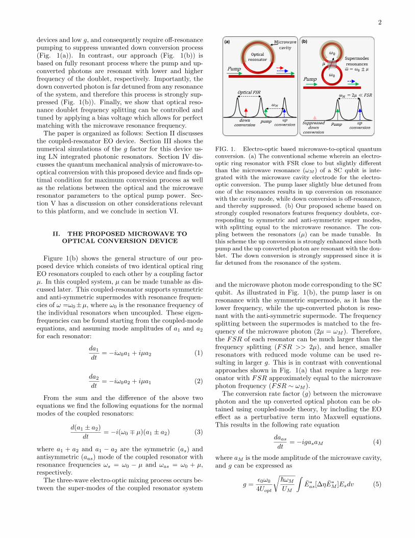
FIG. 1. Electro-optic based microwave-to-optical quantumconversion. (a) The conventional scheme wherein an electro-optic ring resonator with FSR close to but slightly differentthan the microwave resonance (ωM ) of a SC qubit is inte-grated with the microwave cavity electrode for the electro-optic conversion. The pump laser slightly blue detuned fromone of the resonances results in up conversion on resonancewith the cavity mode, while down conversion is off-resonance,and thereby suppressed. (b) Our proposed scheme based onstrongly coupled resonators features frequency doublets, cor-responding to symmetric and anti-symmetric super modes,with splitting equal to the microwave resonance. The cou-pling between the resonators (µ) can be made tunable. Inthis scheme the up conversion is strongly enhanced since bothpump and the up converted photon are resonant with the dou-blet. The down conversion is strongly suppressed since it isfar detuned from the resonance of the system.
and the microwave photon mode corresponding to the SCqubit. As illustrated in Fig. 1(b), the pump laser is onresonance with the symmetric supermode, as it has thelower frequency, while the up-converted photon is reso-nant with the anti-symmetric supermode. The frequencysplitting between the supermodes is matched to the fre-quency of the microwave photon (2µ = ωM ). Therefore,the FSR of each resonator can be much larger than thefrequency splitting (FSR >> 2µ), and hence, smallerresonators with reduced mode volume can be used re-sulting in larger g. This is in contrast with conventionalapproaches shown in Fig. 1(a) that require a large res-onator with FSR approximately equal to the microwavephoton frequency (FSR ∼ ωM ).
The conversion rate factor (g) between the microwavephoton and the up converted optical photon can be ob-tained using coupled-mode theory, by including the EOeffect as a perturbative term into Maxwell equations.This results in the following rate equation
daasdt
= −igasaM (4)
where aM is the mode amplitude of the microwave cavity,and g can be expressed as
g =ε0ω0
4Uopt
√~ωMUM
∫E∗as[∆ηE
∗M ]Esdv (5)
3
In the above expression, the integral is calculated overthe volume of the LN resonator, Es and Eas are the elec-tric fields of the symmetric and anti-symmetric modes ofthe coupled-resonator, EM is the field of the microwavecavity, and ∆η is the electro-optic tensor of the opticalresonator material. UM = CV 2/2 is the microwave res-onator energy, where C and V are the capacitance andthe voltage of the microwave electrode, and Uopt is the op-tical energy of the symmetric and anti-symmetric modesthat have closely similar values. Equation (5) showsthat non-zero g can be achieved only if microwave fieldis not symmetric. This can be accomplished by havingmicrowave field interact with only one optical resonator(e.g. the upper one as shown in Fig. 1(b)) or with bothresonators using a push-pull configuration. In the latter,different voltage polarity is used for each resonator toprovide a non-zero electro-optic mixing.
In order to achieve tripple-resonance condition be-tween optical and microwave fields, it is essential to allowfor dynamical tunability of the coupling factor µ. Sucha tuning knob would allow for any fabrication-inducedchanges to the resonant frequencies to be compensatedfor. To achieve this, we propose the configuration shownin Fig. 2(a): the resonators are coupled at two pointswith 100% coupling, and each resonator has a built-inphase-shifter for the tuning purpose. Using a transfermatrix analysis the symmetric and anti-symmetric eigen-resonances of this coupled resonator can be found as:
ωs,as = ω0 +ngFSR
neff(π ∓ φ) (6)
where neff , ng, and FSR = c/(nglR) are the effectiveindex, group index and the free-spectral-range of the in-dividual resonators, respectively, and c and lR are thespeed of light and the resonator length, respectively. Thephase tuning can be achieved using the same EO effectby applying DC voltage to the electrodes of the phaseshifter, without any power dissipation. Our recent workshows that a nanophotonic LN modulator similar to theones considered here, has Vπ ·L ≈ 2 V.cm. That is 2 V ap-plied across an electrode length of L = 1 cm is sufficientto provide a π phase shift [15]. Using this number, weevaluate the resonance splitting achiavable with DC biasapplied to the phase shifter assuming the FSR = 100GHz for each resonator (Fig. 3). As seen from this fig-ure, a large resonance splitting tuning range is achievablewith a reasonable bias voltage.
III. NUMERICAL ANALYSIS OF g FACTOR
We consider a Z-cut LN as the photonic resonator ma-terial, and two possible configurations for placing the mi-crowave electrodes with respect to the optical resonatoras illustrated in Figs. 4(a) and 4(b). The microwaveelectrodes are interacting only with one of the optical res-onators in the coupled-resonator schemes discussed here.In both cases, optical modes are in telecom wavelength
OutIn
Resonator1
Resonator2
1.5
φ
-φ
Tunablecoupling(µ)
(a) (b)
FIG. 2. (a) Schematic of a coupled-resonator with a tunablecoupling strength that can be used to dynamically control theresonance splitting. The resonators are coupled at two pointsusing directional couplers with 100% coupling (with the cou-pling matrix as shown in the figure), and each has an inte-grated phase-shifter that imparts the phase with the oppositesign. (b) The resonance splitting can expand or contract bycontrolling the phase φ.
0 10 20 300
20
40
60100 μm200 μm300 μm
Phase shifter voltage (V)
Phase shifterlength
Resonancesplitting
(GHz)
FIG. 3. Calculated resonance splitting vs. electrostatic volt-age applied to the phase-shifter for the LN coupled-resonatorwith the structure shown in Fig. 2(a) and for three phase-shifter lengths of 100, 200, and 300 microns as specified inthe figure. For this calculation we assume a phase shift of πis obtained with a 2 V.cm, and use Eq. 6. We also assumethe resonator has an FSR of 100 GHz, ng = 2.39, neff = 2.
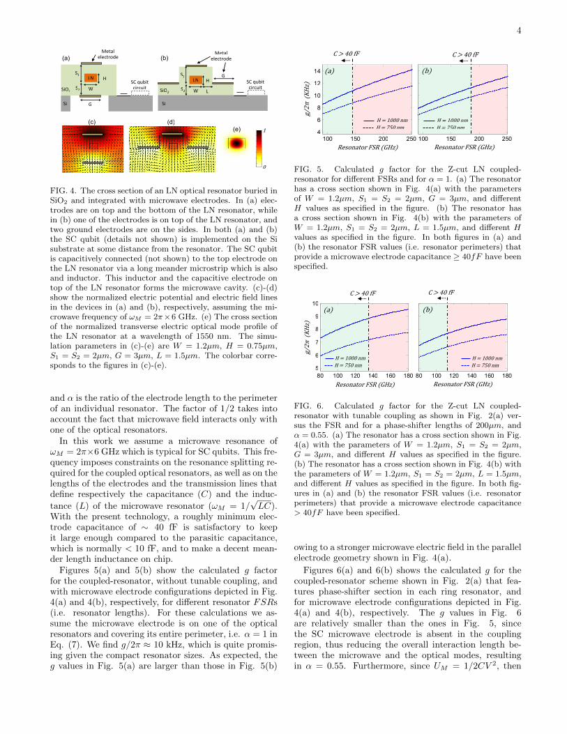
range (∼ 1550 nm). The parallel electrode configurationshown in Fig. 4(a) results in larger g, due to strongervertical electric field, but is somewhat more challengingto fabricate. The SC qubit is made on the silicon layerat some distance from the SiO2 layer to avoid the mi-crowave loss of SiO2 [16]. Figures 4(c) and 4(d) show themicrowave field distributions for the structures in Figs.4(a) and 4(b), respectively. It can be seen that the elec-tric field lines inside the LN resonator are vertical, whichmaximizes the EO effect for the Z-cut LN, and are nearlyuniform across the optical mode profile (Fig. 4(e)). Thisuniformity of the microwave field can be used to simplifyEq. (5) to:
g ≈ n2er33ω0
√~ωMUM
α
2E∗Mz (7)
where ne and r33 are the extraordinary refractive opticalindex (2.138) and the electro-optic coefficient (30 pm/V)of LN, respectively, EMz is the z component of the mi-crowave electric field at the center of the LN resonator,
4
LN
SiO2
Si
Metal electrode (a)
W
HS1
S2
G
LN
(b)
W
HS1
L
GSC qubit circuit
SC qubit circuit S2
Metal electrode
SiO2
Si
(c) (d)
0
1(e)
1
10
20
30
40
50
60
FIG. 4. The cross section of an LN optical resonator buried inSiO2 and integrated with microwave electrodes. In (a) elec-trodes are on top and the bottom of the LN resonator, whilein (b) one of the electrodes is on top of the LN resonator, andtwo ground electrodes are on the sides. In both (a) and (b)the SC qubit (details not shown) is implemented on the Sisubstrate at some distance from the resonator. The SC qubitis capacitively connected (not shown) to the top electrode onthe LN resonator via a long meander microstrip which is alsoand inductor. This inductor and the capacitive electrode ontop of the LN resonator forms the microwave cavity. (c)-(d)show the normalized electric potential and electric field linesin the devices in (a) and (b), respectively, assuming the mi-crowave frequency of ωM = 2π×6 GHz. (e) The cross sectionof the normalized transverse electric optical mode profile ofthe LN resonator at a wavelength of 1550 nm. The simu-lation parameters in (c)-(e) are W = 1.2µm, H = 0.75µm,S1 = S2 = 2µm, G = 3µm, L = 1.5µm. The colorbar corre-sponds to the figures in (c)-(e).
and α is the ratio of the electrode length to the perimeterof an individual resonator. The factor of 1/2 takes intoaccount the fact that microwave field interacts only withone of the optical resonators.
In this work we assume a microwave resonance ofωM = 2π×6 GHz which is typical for SC qubits. This fre-quency imposes constraints on the resonance splitting re-quired for the coupled optical resonators, as well as on thelengths of the electrodes and the transmission lines thatdefine respectively the capacitance (C) and the induc-
tance (L) of the microwave resonator (ωM = 1/√LC).
With the present technology, a roughly minimum elec-trode capacitance of ∼ 40 fF is satisfactory to keepit large enough compared to the parasitic capacitance,which is normally < 10 fF, and to make a decent mean-der length inductance on chip.
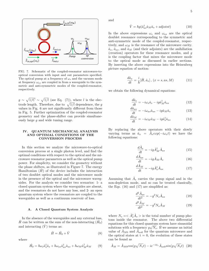
Figures 5(a) and 5(b) show the calculated g factorfor the coupled-resonator, without tunable coupling, andwith microwave electrode configurations depicted in Fig.4(a) and 4(b), respectively, for different resonator FSRs(i.e. resonator lengths). For these calculations we as-sume the microwave electrode is on one of the opticalresonators and covering its entire perimeter, i.e. α = 1 inEq. (7). We find g/2π ≈ 10 kHz, which is quite promis-ing given the compact resonator sizes. As expected, theg values in Fig. 5(a) are larger than those in Fig. 5(b)
100 150 200 2504
6
8
10
12
14
100 150 200 250
6
8
ResonatorFSR(GHz) ResonatorFSR(GHz)
g/2π
(KHz)
(a)
C>40fF
(b)
C>40fF
H=1000nmH=750nm
H=1000nmH=750nm
FIG. 5. Calculated g factor for the Z-cut LN coupled-resonator for different FSRs and for α = 1. (a) The resonatorhas a cross section shown in Fig. 4(a) with the parametersof W = 1.2µm, S1 = S2 = 2µm, G = 3µm, and differentH values as specified in the figure. (b) The resonator hasa cross section shown in Fig. 4(b) with the parameters ofW = 1.2µm, S1 = S2 = 2µm, L = 1.5µm, and different Hvalues as specified in the figure. In both figures in (a) and(b) the resonator FSR values (i.e. resonator perimeters) thatprovide a microwave electrode capacitance ≥ 40fF have beenspecified.
80 100 120 140 160 1805
6
7
8
9
10
80 100 120 140 160 1805
6
7
8
9
10
ResonatorFSR(GHz) ResonatorFSR(GHz)
(a)
C>40fF
(b)
C>40fF
H=1000nmH=750nm
H=1000nmH=750nm
g/2π
(KHz)
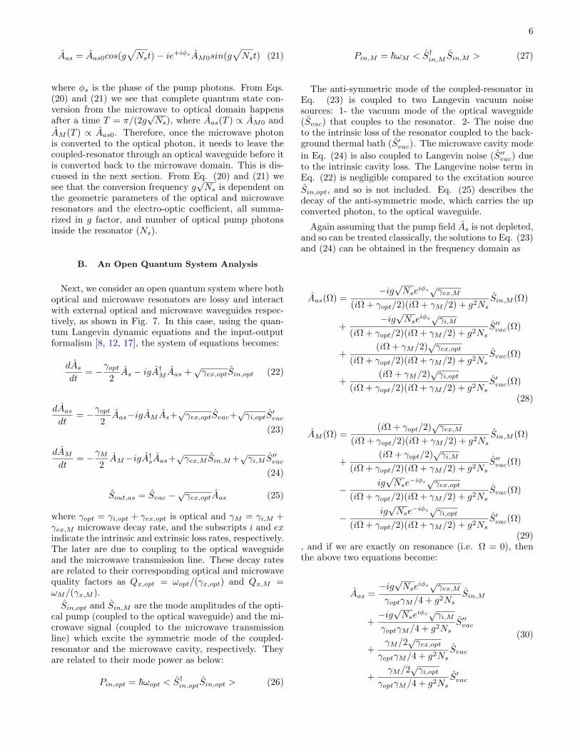
FIG. 6. Calculated g factor for the Z-cut LN coupled-resonator with tunable coupling as shown in Fig. 2(a) ver-sus the FSR and for a phase-shifter lengths of 200µm, andα = 0.55. (a) The resonator has a cross section shown in Fig.4(a) with the parameters of W = 1.2µm, S1 = S2 = 2µm,G = 3µm, and different H values as specified in the figure.(b) The resonator has a cross section shown in Fig. 4(b) withthe parameters of W = 1.2µm, S1 = S2 = 2µm, L = 1.5µm,and different H values as specified in the figure. In both fig-ures in (a) and (b) the resonator FSR values (i.e. resonatorperimeters) that provide a microwave electrode capacitance> 40fF have been specified.
owing to a stronger microwave electric field in the parallelelectrode geometry shown in Fig. 4(a).
Figures 6(a) and 6(b) shows the calculated g for thecoupled-resonator scheme shown in Fig. 2(a) that fea-tures phase-shifter section in each ring resonator, andfor microwave electrode configurations depicted in Fig.4(a) and 4(b), respectively. The g values in Fig. 6are relatively smaller than the ones in Fig. 5, sincethe SC microwave electrode is absent in the couplingregion, thus reducing the overall interaction length be-tween the microwave and the optical modes, resultingin α = 0.55. Furthermore, since UM = 1/2CV 2, then
5
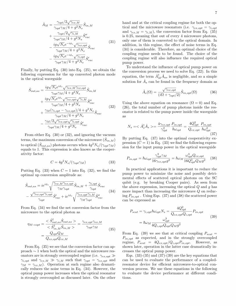
FIG. 7. Schematic of the coupled-resonator microwave-to-optical conversion with input and out parameters specified.The optical pump at a frequency of ωs and the vacuum modeat frequency ωas are coupled in from a waveguide to the sym-metric and anti-symmetric modes of the coupled-resonator,respectively.
g ∼√
1/C ∼√
1/l (see Eq. (7)), where l is the elec-
trode length. Therefore, due to√
1/l dependence, the gvalues in Fig. 6 are not significantly different from thosein Fig. 5. Further optimization of the coupled-resonatorgeometry and the phase-shifter can provide simultane-ously large g and wide tuning range.
IV. QUANTUM MECHANICAL ANALYSISAND OPTIMAL CONDITIONS OF THE
CONVERSION PROCESS
In this section we analyze the microwave-to-opticalconversion process at a single photon level, and find theoptimal conditions with respect to the optical and the mi-crowave resonator parameters as well as the optical pumppower. For simplicity, we consider the geometry withoutthe phase shifters, as illustrated in Figure 7. The energyHamiltonian (H) of the device includes the interactionof two doublet optical modes and the microwave modein the presence of the optical and the microwave waveg-uides. For the analysis we consider two scenarios: 1- aclosed quantum system where the waveguides are absent,and the resonators do not have any loss, and 2- an openquantum system where the resonators are coupled to thewaveguides as well as a continuum reservoir of loss.
A. A Closed Quantum System Analysis
In the absence of the waveguides and any external loss,H can be written as the sum of the non-interacting (H0)
and interacting (V ) terms as:
H = H0 + V (8)
where
H0 = ~ωsa†sas + ~ωasa†asaas + ~ωM a†M aM (9)
and
V = ~g(a†asaM as + adjoint) (10)
In the above expressions ωs and ωas are the opticaldoublet resonance corresponding to the symmetric andanti-symmetric mode of the coupled-resonator, respec-tively, and ωM is the resonance of the microwave cavity.as, aas, and aM (and their adjoints) are the anihiliation(creation) operators for these resonance modes, and gis the coupling factor that mixes the microwave modeto the optical mode as discussed in earlier sections.By inserting the above expressions into the Heisenbergpicture equation of motion:
daxdt
=i
~[H, ax] , (x = s, as,M) (11)
we obtain the following dynamical equations:
dasdt
= −iωsas − iga†M aas (12)
daasdt
= −iωasaas − igaM as (13)
daMdt
= −iωM aM − iga†saas (14)
By replacing the above operators with their slowlyvarying terms as ax = Axexp(−iωxt) we have thefollowing equations:
dAsdt
= −igA†M Aas (15)
dAasdt
= −igAM As (16)
dAMdt
= −igA†sAas (17)
Assuming that As carries the pump signal and in thenon-depletion mode, and so can be treated classically,the Eqs. (16) and (17) are simplified as:
d2Aasdt2
= −g2NsAas (18)
d2AMdt2
= −g2NsAM (19)
where Ns =< A†sAs > is the total number of pump pho-tons inside the resonator. The above two differentialequations for this closed quantum system have sinusoidalsolutions with a frequency g
√Ns. If we assume an initial
value of AM0 and Aas0 for the quantum microwave andthe optical states at t = 0, the evolution of these statescan be found as
AM = AM0cos(g√Nst)− ie−iφsAas0sin(g
√Nst) (20)
6
Aas = Aas0cos(g√Nst)− ie+iφsAM0sin(g
√Nst) (21)
where φs is the phase of the pump photons. From Eqs.(20) and (21) we see that complete quantum state con-version from the microwave to optical domain happensafter a time T = π/(2g
√Ns), where Aas(T ) ∝ AM0 and
AM (T ) ∝ Aas0. Therefore, once the microwave photonis converted to the optical photon, it needs to leave thecoupled-resonator through an optical waveguide before itis converted back to the microwave domain. This is dis-cussed in the next section. From Eq. (20) and (21) wesee that the conversion frequency g
√Ns is dependent on
the geometric parameters of the optical and microwaveresonators and the electro-optic coefficient, all summa-rized in g factor, and number of optical pump photonsinside the resonator (Ns).
B. An Open Quantum System Analysis
Next, we consider an open quantum system where bothoptical and microwave resonators are lossy and interactwith external optical and microwave waveguides respec-tively, as shown in Fig. 7. In this case, using the quan-tum Langevin dynamic equations and the input-outputformalism [8, 12, 17], the system of equations becomes:
dAsdt
= −γopt2As − igA†M Aas +
√γex,optSin,opt (22)
dAasdt
= −γopt2Aas−igAM As+
√γex,optSvac+
√γi,optS
′vac
(23)
dAMdt
= −γM2AM−igA†sAas+
√γex,M Sin,M+
√γi,M S
′′vac
(24)
Sout,as = Svac −√γex,optAas (25)
where γopt = γi,opt + γex,opt is optical and γM = γi,M +γex,M microwave decay rate, and the subscripts i and exindicate the intrinsic and extrinsic loss rates, respectively.The later are due to coupling to the optical waveguideand the microwave transmission line. These decay ratesare related to their corresponding optical and microwavequality factors as Qx,opt = ωopt/(γx,opt) and Qx,M =ωM/(γx,M ).
Sin,opt and Sin,M are the mode amplitudes of the opti-cal pump (coupled to the optical waveguide) and the mi-crowave signal (coupled to the microwave transmissionline) which excite the symmetric mode of the coupled-resonator and the microwave cavity, respectively. Theyare related to their mode power as below:
Pin,opt = ~ωopt < S†in,optSin,opt > (26)
Pin,M = ~ωM < S†in,M Sin,M > (27)
The anti-symmetric mode of the coupled-resonator inEq. (23) is coupled to two Langevin vacuum noisesources: 1- the vacuum mode of the optical waveguide(Svac) that couples to the resonator. 2- The noise dueto the intrinsic loss of the resonator coupled to the back-ground thermal bath (S′vac). The microwave cavity mode
in Eq. (24) is also coupled to Langevin noise (S′′vac) dueto the intrinsic cavity loss. The Langevine noise term inEq. (22) is negligible compared to the excitation source
Sin,opt, and so is not included. Eq. (25) describes thedecay of the anti-symmetric mode, which carries the upconverted photon, to the optical waveguide.
Again assuming that the pump field As is not depleted,and so can be treated classically, the solutions to Eq. (23)and (24) can be obtained in the frequency domain as
Aas(Ω) =−ig√Nse
iφs√γex,M
(iΩ + γopt/2)(iΩ + γM/2) + g2NsSin,M (Ω)
+−ig√Nse
iφs√γi,M
(iΩ + γopt/2)(iΩ + γM/2) + g2NsS′′vac(Ω)
+(iΩ + γM/2)
√γex,opt
(iΩ + γopt/2)(iΩ + γM/2) + g2NsSvac(Ω)
+(iΩ + γM/2)
√γi,opt
(iΩ + γopt/2)(iΩ + γM/2) + g2NsS′vac(Ω)
(28)
AM (Ω) =(iΩ + γopt/2)
√γex,M
(iΩ + γopt/2)(iΩ + γM/2) + g2NsSin,M (Ω)
+(iΩ + γopt/2)
√γi,M
(iΩ + γopt/2)(iΩ + γM/2) + g2NsS′′vac(Ω)
−ig√Nse
−iφs√γex,opt
(iΩ + γopt/2)(iΩ + γM/2) + g2NsSvac(Ω)
−ig√Nse
−iφs√γi,opt
(iΩ + γopt/2)(iΩ + γM/2) + g2NsS′vac(Ω)
(29), and if we are exactly on resonance (i.e. Ω = 0), thenthe above two equations become:
Aas =−ig√Nse
iφs√γex,M
γoptγM/4 + g2NsSin,M
+−ig√Nse
iφs√γi,M
γoptγM/4 + g2NsS′′vac
+γM/2
√γex,opt
γoptγM/4 + g2NsSvac
+γM/2
√γi,opt
γoptγM/4 + g2NsS′vac
(30)
7
AM =γopt/2
√γex,M
γoptγM/4 + g2NsSin,M
+γopt/2
√γi,M
γoptγM/4 + g2NsS′′vac
−ig√Nse
−iφs√γex,opt
γoptγM/4 + g2NsSvac
−ig√Nse
−iφs√γi,opt
γoptγM/4 + g2NsS′vac
(31)
Finally, by putting Eq. (30) into Eq. (25), we obtain thefollowing expression for the up converted photon modein the optical waveguide
Sout,as =ig√Nse
iφs√γex,Mγex,opt
γoptγM/4 + g2NsSin,M
+ig√Nse
iφs√γex,opt
√γi,M
γoptγM/4 + g2NsS′′vac
+γM (γi,opt − γex,opt)/4 + g2Ns
γoptγM/4 + g2NsSvac
−γM/2
√γex,opt
√γi,opt
γoptγM/4 + g2NsS′vac
(32)
From either Eq. (30) or (32), and ignoring the vacuum
terms, the maximum conversion of the microwave (Sin,M )
to optical (Sout,as) photons occurs when 4g2Ns/(γoptγM )equals to 1. This expression is also knows as the cooper-ativity factor:
C = 4g2Ns/(γoptγM ) (33)
Putting Eq. (33) when C = 1 into Eq. (32), we find theoptimal up conversion amplitude as:
Sout,as = ieiφs
√γex,Mγex,optγMγopt
Sin,M +γi,optγopt
Svac
−√γex,optγi,opt
γoptS′vac + ieiφs
√γex,optγi,MγMγopt
S′′vac
(34)
From Eq. (34) we find the net conversion factor from themicrowave to the optical photon as
ηM→opt =< S†out,asSout,as >
< S†in,M Sin,M >=γex,optγex,MγoptγM
=QoptQM
Qex,optQex,M
(35)
From Eq. (35) we see that the conversion factor can ap-proach ∼ 1 when both the optical and the microwave res-onators are in strongly overcoupled regime (i.e. γex,opt γi,opt and γex,M γi,M such that γopt = γex,opt andγM = γex,M ). Operation at such regime also dramati-cally reduces the noise terms in Eq. (34). However, theoptical pump power increases when the optical resonatoris strongly overcoupled as discussed later. On the other
hand and at the critical coupling regime for both the op-tical and the microwave resonators (i.e. γex,opt = γi,optand γex,M = γi,M ), the conversion factor from Eq. (35)is 0.25, meaning that out of every 4 microwave photons,only one of them is converted to the optical domain. Inaddition, in this regime, the effect of noise terms in Eq.(34) is considerable. Therefore, an optimal choice of thecoupling regime needs to be found. The choice of thecoupling regime will also influence the required opticalpump power.
To understand the influence of optical pump power onthe conversion process we need to solve Eq. (22). In this
equation, the term A†M Aas is negligible, and so a simple
solution for As can be found in the frequency domain as
As(Ω) =
√γex,opt
(iΩ + γopt/2)Sin,opt(Ω) (36)
Using the above equation on resonance (Ω = 0) and Eq.(26), the total number of pump photons inside the res-onator is related to the pump power inside the waveguideas
Ns =< A†sAs >=4γex,optγ2opt
Pin,opt~ωopt
=4Q2
opt
Qex,opt
Pin,opt~ω2
opt
(37)By putting Eq. (37) into the optimal cooperativity ex-pression (C = 1) in Eq. (33) we find the following expres-sion for the input pump power in the optical waveguide
Pin,opt = ~ωoptγ3optγM
16γex,optg2= ~ωM
ω3optQex,opt
16Q3optQMg
2(38)
In practical applications it is important to reduce thepump power to minimize the noise and possibly detri-mental effects of scattered optical photons on the SCqubit (e.g. by breaking Cooper pairs). As seen fromthe above expression, increasing the optical Q and g hasmore impact than increasing the microwave Q on reduc-ing Pin,opt . Using Eqs. (37) and (38) the scattered powercan be expressed as
Pscat = γi,opt~ωoptNs =4Q2
opt
Qex,optQi,optPin,opt
= ~ωMω3opt
4Qi,optQoptQMg2
(39)
From Eq. (39) we see that at critical coupling Pscat =Pin,opt as expected, and in the strongly overcoupledregime, Pscat = 4Qex,opt/Qi,optPin,opt. However, asshown later, operation in the latter case dramatically in-creases the optical pump power.
Eqs. (33)-(35) and (37)-(39) are the key equations thatcan be used to evaluate the performance of a coupled-resonator device for efficient microwave-to-optical con-version process. We use these equations in the followingto evaluate the device performance at different condi-tions.
8
1 1010
0
101
102
103
104
105
106
1 1010
4
105
106
107
108
109
P in,opt(μW)
Ns
(a) (b)
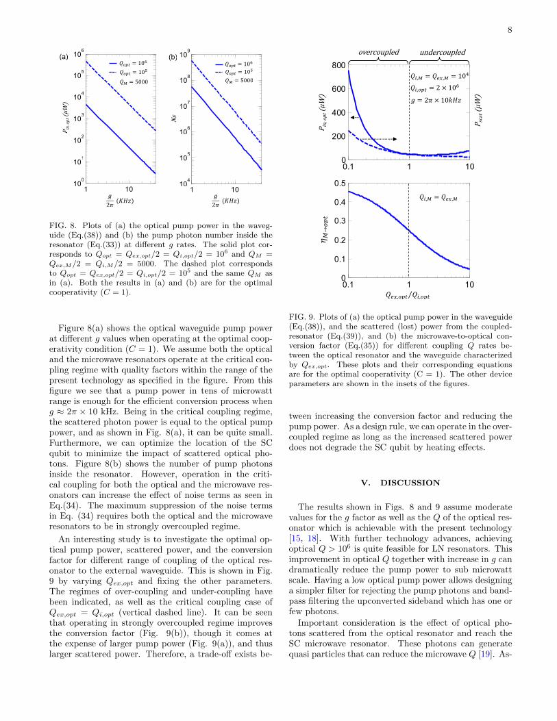
FIG. 8. Plots of (a) the optical pump power in the waveg-uide (Eq.(38)) and (b) the pump photon number inside theresonator (Eq.(33)) at different g rates. The solid plot cor-responds to Qopt = Qex,opt/2 = Qi,opt/2 = 106 and QM =Qex,M/2 = Qi,M/2 = 5000. The dashed plot correspondsto Qopt = Qex,opt/2 = Qi,opt/2 = 105 and the same QM asin (a). Both the results in (a) and (b) are for the optimalcooperativity (C = 1).
Figure 8(a) shows the optical waveguide pump powerat different g values when operating at the optimal coop-erativity condition (C = 1). We assume both the opticaland the microwave resonators operate at the critical cou-pling regime with quality factors within the range of thepresent technology as specified in the figure. From thisfigure we see that a pump power in tens of microwattrange is enough for the efficient conversion process wheng ≈ 2π × 10 kHz. Being in the critical coupling regime,the scattered photon power is equal to the optical pumppower, and as shown in Fig. 8(a), it can be quite small.Furthermore, we can optimize the location of the SCqubit to minimize the impact of scattered optical pho-tons. Figure 8(b) shows the number of pump photonsinside the resonator. However, operation in the criti-cal coupling for both the optical and the microwave res-onators can increase the effect of noise terms as seen inEq.(34). The maximum suppression of the noise termsin Eq. (34) requires both the optical and the microwaveresonators to be in strongly overcoupled regime.
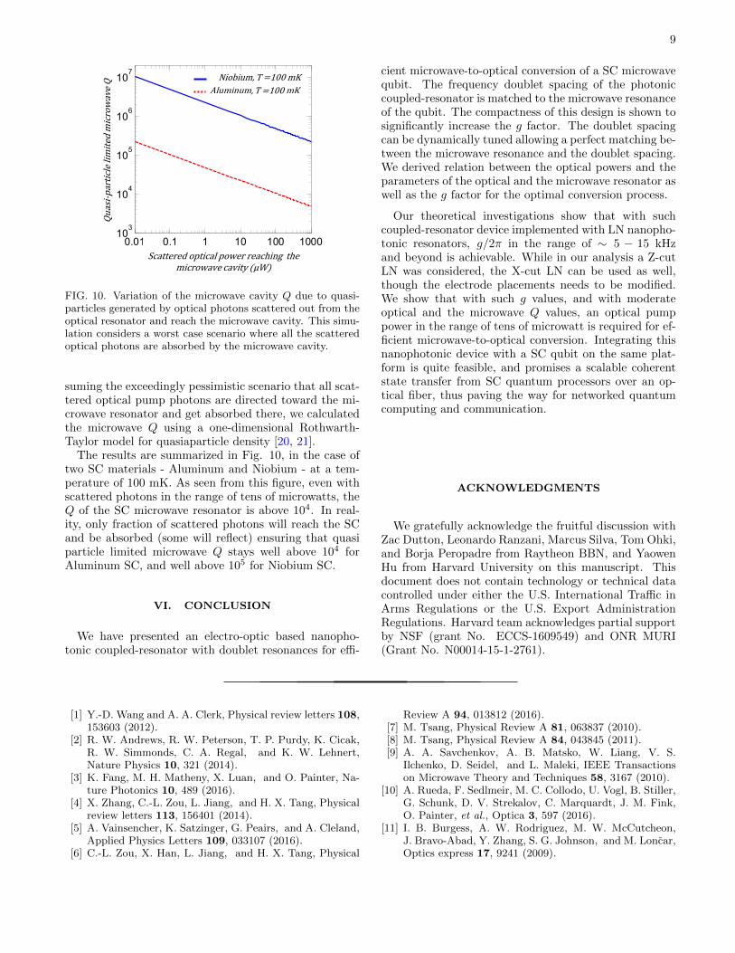
An interesting study is to investigate the optimal op-tical pump power, scattered power, and the conversionfactor for different range of coupling of the optical res-onator to the external waveguide. This is shown in Fig.9 by varying Qex,opt and fixing the other parameters.The regimes of over-coupling and under-coupling havebeen indicated, as well as the critical coupling case ofQex,opt = Qi,opt (vertical dashed line). It can be seenthat operating in strongly overcoupled regime improvesthe conversion factor (Fig. 9(b)), though it comes atthe expense of larger pump power (Fig. 9(a)), and thuslarger scattered power. Therefore, a trade-off exists be-
0.1 1 100
0.1
0.2
0.3
0.4
0.5
0.1 1 100
200
400
600
800
overcoupled undercoupled
P scat(μW)
P in,opt(μW)
FIG. 9. Plots of (a) the optical pump power in the waveguide(Eq.(38)), and the scattered (lost) power from the coupled-resonator (Eq.(39)), and (b) the microwave-to-optical con-version factor (Eq.(35)) for different coupling Q rates be-tween the optical resonator and the waveguide characterizedby Qex,opt. These plots and their corresponding equationsare for the optimal cooperativity (C = 1). The other deviceparameters are shown in the insets of the figures.
tween increasing the conversion factor and reducing thepump power. As a design rule, we can operate in the over-coupled regime as long as the increased scattered powerdoes not degrade the SC qubit by heating effects.
V. DISCUSSION
The results shown in Figs. 8 and 9 assume moderatevalues for the g factor as well as the Q of the optical res-onator which is achievable with the present technology[15, 18]. With further technology advances, achievingoptical Q > 106 is quite feasible for LN resonators. Thisimprovement in optical Q together with increase in g candramatically reduce the pump power to sub microwattscale. Having a low optical pump power allows designinga simpler filter for rejecting the pump photons and band-pass filtering the upconverted sideband which has one orfew photons.
Important consideration is the effect of optical pho-tons scattered from the optical resonator and reach theSC microwave resonator. These photons can generatequasi particles that can reduce the microwave Q [19]. As-
9
0.01 0.1 1 10 100 100010
3
104
105
106
107
Scatteredopticalpowerreaching themicrowavecavity(μW)
Quasi-particlelim
itedmicrowaveQ Niobium,T=100mK
Aluminum,T=100mK
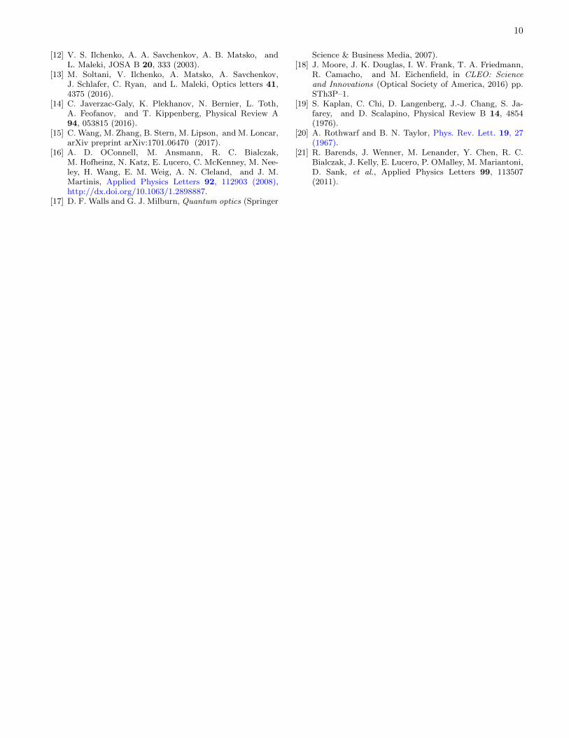
FIG. 10. Variation of the microwave cavity Q due to quasi-particles generated by optical photons scattered out from theoptical resonator and reach the microwave cavity. This simu-lation considers a worst case scenario where all the scatteredoptical photons are absorbed by the microwave cavity.
suming the exceedingly pessimistic scenario that all scat-tered optical pump photons are directed toward the mi-crowave resonator and get absorbed there, we calculatedthe microwave Q using a one-dimensional Rothwarth-Taylor model for quasiaparticle density [20, 21].
The results are summarized in Fig. 10, in the case oftwo SC materials - Aluminum and Niobium - at a tem-perature of 100 mK. As seen from this figure, even withscattered photons in the range of tens of microwatts, theQ of the SC microwave resonator is above 104. In real-ity, only fraction of scattered photons will reach the SCand be absorbed (some will reflect) ensuring that quasiparticle limited microwave Q stays well above 104 forAluminum SC, and well above 105 for Niobium SC.
VI. CONCLUSION
We have presented an electro-optic based nanopho-tonic coupled-resonator with doublet resonances for effi-
cient microwave-to-optical conversion of a SC microwavequbit. The frequency doublet spacing of the photoniccoupled-resonator is matched to the microwave resonanceof the qubit. The compactness of this design is shown tosignificantly increase the g factor. The doublet spacingcan be dynamically tuned allowing a perfect matching be-tween the microwave resonance and the doublet spacing.We derived relation between the optical powers and theparameters of the optical and the microwave resonator aswell as the g factor for the optimal conversion process.
Our theoretical investigations show that with suchcoupled-resonator device implemented with LN nanopho-tonic resonators, g/2π in the range of ∼ 5 − 15 kHzand beyond is achievable. While in our analysis a Z-cutLN was considered, the X-cut LN can be used as well,though the electrode placements needs to be modified.We show that with such g values, and with moderateoptical and the microwave Q values, an optical pumppower in the range of tens of microwatt is required for ef-ficient microwave-to-optical conversion. Integrating thisnanophotonic device with a SC qubit on the same plat-form is quite feasible, and promises a scalable coherentstate transfer from SC quantum processors over an op-tical fiber, thus paving the way for networked quantumcomputing and communication.
ACKNOWLEDGMENTS
We gratefully acknowledge the fruitful discussion withZac Dutton, Leonardo Ranzani, Marcus Silva, Tom Ohki,and Borja Peropadre from Raytheon BBN, and YaowenHu from Harvard University on this manuscript. Thisdocument does not contain technology or technical datacontrolled under either the U.S. International Traffic inArms Regulations or the U.S. Export AdministrationRegulations. Harvard team acknowledges partial supportby NSF (grant No. ECCS-1609549) and ONR MURI(Grant No. N00014-15-1-2761).
[1] Y.-D. Wang and A. A. Clerk, Physical review letters 108,153603 (2012).
[2] R. W. Andrews, R. W. Peterson, T. P. Purdy, K. Cicak,R. W. Simmonds, C. A. Regal, and K. W. Lehnert,Nature Physics 10, 321 (2014).
[3] K. Fang, M. H. Matheny, X. Luan, and O. Painter, Na-ture Photonics 10, 489 (2016).
[4] X. Zhang, C.-L. Zou, L. Jiang, and H. X. Tang, Physicalreview letters 113, 156401 (2014).
[5] A. Vainsencher, K. Satzinger, G. Peairs, and A. Cleland,Applied Physics Letters 109, 033107 (2016).
[6] C.-L. Zou, X. Han, L. Jiang, and H. X. Tang, Physical
Review A 94, 013812 (2016).[7] M. Tsang, Physical Review A 81, 063837 (2010).[8] M. Tsang, Physical Review A 84, 043845 (2011).[9] A. A. Savchenkov, A. B. Matsko, W. Liang, V. S.
Ilchenko, D. Seidel, and L. Maleki, IEEE Transactionson Microwave Theory and Techniques 58, 3167 (2010).
[10] A. Rueda, F. Sedlmeir, M. C. Collodo, U. Vogl, B. Stiller,G. Schunk, D. V. Strekalov, C. Marquardt, J. M. Fink,O. Painter, et al., Optica 3, 597 (2016).
[11] I. B. Burgess, A. W. Rodriguez, M. W. McCutcheon,J. Bravo-Abad, Y. Zhang, S. G. Johnson, and M. Loncar,Optics express 17, 9241 (2009).
10
[12] V. S. Ilchenko, A. A. Savchenkov, A. B. Matsko, andL. Maleki, JOSA B 20, 333 (2003).
[13] M. Soltani, V. Ilchenko, A. Matsko, A. Savchenkov,J. Schlafer, C. Ryan, and L. Maleki, Optics letters 41,4375 (2016).
[14] C. Javerzac-Galy, K. Plekhanov, N. Bernier, L. Toth,A. Feofanov, and T. Kippenberg, Physical Review A94, 053815 (2016).
[15] C. Wang, M. Zhang, B. Stern, M. Lipson, and M. Loncar,arXiv preprint arXiv:1701.06470 (2017).
[16] A. D. OConnell, M. Ansmann, R. C. Bialczak,M. Hofheinz, N. Katz, E. Lucero, C. McKenney, M. Nee-ley, H. Wang, E. M. Weig, A. N. Cleland, and J. M.Martinis, Applied Physics Letters 92, 112903 (2008),http://dx.doi.org/10.1063/1.2898887.
[17] D. F. Walls and G. J. Milburn, Quantum optics (Springer
Science & Business Media, 2007).[18] J. Moore, J. K. Douglas, I. W. Frank, T. A. Friedmann,
R. Camacho, and M. Eichenfield, in CLEO: Scienceand Innovations (Optical Society of America, 2016) pp.STh3P–1.
[19] S. Kaplan, C. Chi, D. Langenberg, J.-J. Chang, S. Ja-farey, and D. Scalapino, Physical Review B 14, 4854(1976).
[20] A. Rothwarf and B. N. Taylor, Phys. Rev. Lett. 19, 27(1967).
[21] R. Barends, J. Wenner, M. Lenander, Y. Chen, R. C.Bialczak, J. Kelly, E. Lucero, P. OMalley, M. Mariantoni,D. Sank, et al., Applied Physics Letters 99, 113507(2011).


![Erbium-implanted high-Q silica toroidal microcavity laser ... · The analysis is based on the coupled-mode formalism for the resonator coupled to an external waveguide [19–23] with](https://img.pdfslide.us/doc/110x75/606e74385f62b048806806b4/erbium-implanted-high-q-silica-toroidal-microcavity-laser-the-analysis-is-based.jpg)