Embed Size (px)
Citation preview

Simplified Aircraft Design Spreadsheet for HomebuildersVersion 1.0 Copyright C 2003 by Daniel P. Raymer. All Rights Reserved. See legal notice for further restrictions.
LEGAL NOTICE ! Better to save this spreadsheet as a renamed copy before changing it for your airplane, in case it gets messed up!
Inputs Calculated ValuesStall speed (kts) 8 Stall speed (ft/sec) 13.5Takeoff air density (slugs/ft^3) 0.00238 Dynamic pressure (psf) 0.2Wing CLmax 1 Wing loading (W/S) (psf) 0.22
power loading (lb/hp) 0.14
Engine Power (hp -each) 1.65 Wo (lb) 0.2Number of Engines 1 Wing Area (sq ft) 1.1
Swet/Sref 4.2Cfe 0.0053 Cdo 0.0223Aspect ratio (A) 6.3 K (=1/piAe) 0.0674Cruise air density (slugs/ft^3) 0.00176 W/S cruise 0.2Cruise velocity (kts) 24 Cruise velocity (ft/sec) 40.5
Dynamic pressure (psf) 1.4L/D cruise 6.21
Engine SFC 0.45 Engine SFC 0.000125Prop Efficiency (cruise) 0.75Range (nmi) 800 Range (ft) 4860800
Breguet Exponent 0.2373Wf/Wo 0.2310
Fuel allowance (%) 6 Wf/Wo with allow. 0.2448Empty Weight constant "a" 11.86Weight - crew (lbs) 0Weight - Passengers (lbs) 0Weight - payload (lbs) 0 See Sizing Graph sheet for Wo Results
Wing taper ratio 0 Wing Span (ft) 2.59Root Chord (ft) 0.82Tip Chord (ft) 0.00Mean Chord (ft) 0.55
Horizontal tail arm (ft) 10 Tail areas:Cht (volume coeff) 0.6 Sht (horizontal) (sq ft) 0.03Vertical tail arm (ft) 10Cvt (volume coeff) 0.04 Svt (vertical) (sq ft) 0.01
Shar
e -
war
e !
Win
g Lo
adin
gW
o -k
now
n en
gine
If sizing to a range requirement, ignore this input for now but enter it later when Wo is calculated and engine is selected
You cannot enter Wo! Engine power and power loading are multiplied to calculate Wo. If sizing to a range requirement, do calculation below, read Wo from graph, and select an engine that gives the desired Wo=P*P/W
Wo
Sizi
ng to
a ra
nge
requ
irem
ent (
engi
ne is
no
t yet
sel
ecte
d)
(lb/hour /bhp)
(lb/sec /bhp)
Win
g G
eom
etry
Tail
Sizi
ng

Simplified Aircraft Design Spreadsheet for HomebuildersVersion 1.0 Copyright C 2003 by Daniel P. Raymer. All Rights Reserved. See legal notice for further restrictions.
Better to save this spreadsheet as a renamed copy before changing it for your airplane, in case it gets messed up! Send problems & questions to [email protected]
Other Factors Used Equations (from book) Misc Useful Calcs
e (Oswald) 0.75Wcruise/Wo 0.98
CL-cruise 0.1472
Non-cruise weight allowance 0.975
Empty Weight exponent -0.09 Fuel Weight 0.1 (lbs)Fuel Vol 0.0 (gal)
Enter items in blue and purple. Come back and re-enter purple items after the drawing is analyzed.
(OK to change these if you know what you are doing)
Preliminary tail sizing using these methods does not guarantee that the aircraft will be stable, controllable, or safe. You must perform stability calculations after doing your design layout!
LD
=1
qCD 0
W /S+(W /S ) K
q
q= 12ρV
Stall2
WS
=qC L
CD0=C fe
Swet
Sref
K=1
0 .75 π A=0 .424A
W f /W 0=1−0 .975 e
−R c bhp500 ηp L /D
W 0=W people+W payload
1−W E /W 0−W F /W 0
W E /W 0=aW0−0 . 09

Send problems & questions to [email protected]

Sizing Calculations
Wo guess We/Wo We Wo calculated1000 6.3692 6369.2 0.01500 6.1410 9211.4 0.02000 5.9840 11968.0 0.02500 5.8650 14662.6 0.0
Enter Wo from graph (lbs) 2000Pick engine with horsepower of at least: 14286
Power of Selected Engine: 120Calculated Power Loading: 16.67
Pick Wo from graph, where the two lines cross. Enter this value below to find the minimum horsepower engine for your power loading.
If sizing graph lines do not cross, change Wo-guess values above.
Now find a suitable engine of at least this horsepower and enter its power below:
Now go to sheet 1 and enter the power of your selected engine and the power loading calculated above in the
boxes this color. 800 1000 1200 1400 1600 1800 2000 2200 2400 26000
500
1000
1500
2000
2500
3000Sizing Graph
Wo Guess
Wo
Cal
cula
ted

800 1000 1200 1400 1600 1800 2000 2200 2400 26000
500
1000
1500
2000
2500
3000Sizing Graph
Wo Guess
Wo
Cal
cula
ted

As-Drawn Performance Calculations for Simplified Aircraft Design for HomebuildersUse this sheet for performance calculations after you have drawn your design and measured its geometry.
Calculated ValuesWo (lb) 0 wing loading (W/S) (psf) 0.22Engine Power (hp) 2 stall speed (ft/sec) 13.51Number of Engines 1 stall speed (kts) 8.00Engine SFC (lb/hour /bhp) 0.45 power loading (lb/hp) 0.14Wing Area (sq ft) 1.1 Takeoff Parameter 0.0Cdo 0.0223 Takeoff Groundroll (ft) -49.7K (=1/piAe) 0.0674 Takeoff to 50 ft (ft) 50.3Wing CLmax 1Takeoff air density (slugs/ft^3) 0.00238e (Oswald) 0.75Wcruise/Wo 0.98 Cruise Weight (lb) 0.22638Non-cruise weight allowance 0.975Fuel allowance (%) 6Weight - crew (lbs) 0Weight - passengers (lbs) 0Weight - payload (lbs) 0Empty Weight (lbs) 3.1
Other InputsPropeller Diameter (ft) 5Engine RPM (rev/min) 2700Cooling Power Loss (%) 6Cruise Power Setting (% of SL hp) 62Cruise air density (slug/ft^3) 0.00176 Power Coefficient Cp 0.0018
Go to next sheet for climb, cruise, and maximum speed calculations then return here
Cruise speed (kts) 180 Cruise speed (ft/sec) 304.02Cruise Advance Ratio J 1.3512
Cruise Prop efficiency 0.85 Cruise q (psf) 81.3Cruise W/S (psf) 0.2Cruise L/D 0.1Wfuel (total) (lbs) -3Wfuel (usable) (lbs) -3Wfuel (cruise) (lbs) -3log term 0.0760378Range (ft) -1133175Range (nmi) -187
Values from Sheet 1 - OK to change these here, but then link from Sheet 1 is lost

As-Drawn Performance Calculations for Simplified Aircraft Design for HomebuildersUse this sheet for performance calculations after you have drawn your design and measured its geometry.
Equations (from book)
T .O .P .=1.21
WS
Whp
C Lmax
LD
=1
qCD 0
W /S+(W /S ) K
q
R=550 ηp
Cbhp
LDln [ 0 .975W 0
W 0−W f (usable ) ]

Climb, Cruise, & Max Speed Calculations for Simplified Aircraft Design for HomebuildersUse this sheet for performance calculations after you have drawn your design and measured its geometry.
V kts V ft/sec CL CD Drag lbs50 84.45 0.375333 0.59 5.959734 3.695035 6.2759862 0.034618 0.022341 0.149075
100 168.9 0.750667 0.8 4.040497 2.505108 25.1039448 0.008655 0.022265 0.59428150 253.35 1.126 0.85 2.862019 1.774452 56.4838758 0.003846 0.022261 1.336887200 337.8 1.501333 0.82 2.070755 1.283868 100.415779 0.002164 0.02226 2.376616220 371.58 1.651467 0.8 1.83659 1.138686 121.503093 0.001788 0.02226 2.875692
Input adjusted values
Advance Ratio J
Propeller Efficiency
Total Thrust lbs
Cruise Thrust lbs
Dynamic pressure q
Read Cruise speed where cruise thrust line crosses drag line and enter in cruise speed box (this color) on previous sheet
40 60 80 100 120 140 160 180 200 220 2400
200Maximum & Cruise Speed
Total ThrustCruise ThrustDrag
Velocity - kts
Thru
st o
r Dra
g -lb
s
40 60 80 100 120 140 160 180 200 220 2400
9500190002850038000475005700066500760008550095000
104500114000123500133000142500152000
Rate of Climb - Sea Level
Velocity - kts
Clim
b - f
pm

Climb, Cruise, & Max Speed Calculations for Simplified Aircraft Design for HomebuildersUse this sheet for performance calculations after you have drawn your design and measured its geometry.
Equations (from book)
Climb (fps)130058.34154271.42102409.77-27384.02
-102335Read Cruise speed where cruise thrust line crosses drag line and enter in cruise speed box (this color) on previous
40 60 80 100 120 140 160 180 200 220 2400
9500190002850038000475005700066500760008550095000
104500114000123500133000142500152000
Rate of Climb - Sea Level
Velocity - kts
Clim
b - f
pm
D=qS(CD 0+KC L2)
CL−cruise=
WS
qq= 12ρV 2
Vv=V [ TW −1
L/D ]

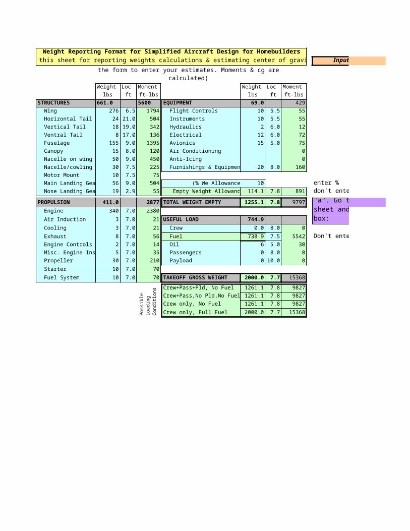
Weight Reporting Format for Simplified Aircraft Design for HomebuildersUse this sheet for reporting weights calculations & estimating center of gravity. Input only items in blue
Weight Loc Moment Weight Loc Momentlbs ft ft-lbs lbs ft ft-lbs
STRUCTURES 661.0 5600 EQUIPMENT 69.0 429 Wing 276 6.5 1794 Flight Controls 10 5.5 55 Horizontal Tail 24 21.0 504 Instruments 10 5.5 55 Vertical Tail 18 19.0 342 Hydraulics 2 6.0 12 Ventral Tail 8 17.0 136 Electrical 12 6.0 72 Fuselage 155 9.0 1395 Avionics 15 5.0 75 Canopy 15 8.0 120 Air Conditioning 0 Nacelle on wing 50 9.0 450 Anti-Icing 0 Nacelle/cowling 30 7.5 225 Furnishings & Equipment 20 8.0 160 Motor Mount 10 7.5 75 Main Landing Gear 56 9.0 504 (% We Allowance) 10 enter % Nose Landing Gear 19 2.9 55 Empty Weight Allowance 114.1 7.8 891 don’t enter these
PROPULSION 411.0 2877 TOTAL WEIGHT EMPTY 1255.1 7.8 9797 Engine 340 7.0 2380 Air Induction 3 7.0 21 USEFUL LOAD 744.9 Cooling 3 7.0 21 Crew 0.0 8.0 0 Exhaust 8 7.0 56 Fuel 738.9 7.5 5542 Don't enter this! It is calculated from Wo, We, and other Useful Load Group items Engine Controls 2 7.0 14 Oil 6 5.0 30 Misc. Engine Inst 5 7.0 35 Passengers 0 8.0 0 Propeller 30 7.0 210 Payload 0 10.0 0 Starter 10 7.0 70 Fuel System 10 7.0 70 TAKEOFF GROSS WEIGHT 2000.0 7.7 15368
Crew+Pass+Pld, No Fuel 1261.1 7.8 9827Crew+Pass,No Pld,No Fuel 1261.1 7.8 9827Crew only, No Fuel 1261.1 7.8 9827Crew only, Full Fuel 2000.0 7.7 15368
(Sorry, no weights estimation methods here, just the form to enter your estimates. Moments & cg are calculated)
Calculated Empty Weight constant "a". Go to Initial Sizing Inputs sheet and revise value in purple box:
Pos
sibl
e Lo
adin
g C
ondi
tions
Input only items in blue
1.2438
Don't enter this! It is calculated from Wo, We, and other Useful Load Group items
Calculated Empty Weight constant "a". Go to Initial Sizing Inputs sheet and revise value in purple box:

ASPECT RATIO OPTIMIZATION: DR-4
A-baseline 6.3Wo 0.2Wwing-base 276We-base 1255.1 Read performance results and enter here
A A/Abase Delta We We-new Range ROC6 0.95 0.97 -8 1247 1165 212 175 2200
6.3 1.00 1.00 0 1255 964 220 180 240014 2.22 1.61 170 1425 760 221 181 2500
Wwing/ Ww-base
Max Speed
Cruise Speed
Enter delta on Weight sheet (I stuck it in the unused Anti-Ice entry), and change aspect ratio and empty weight "a" factor on Initial Sizing Sheet
6 8 10 12 140
500
1000
1500
2000
2500Aspect Ratio Trade Study
RangeMax Speed *10Cruise Speed *10Rate of Climb
Aspect Ratio
nmi,
kts,
or f
pm

max*10 cruise*102120 17502200 18002210 1810
6 8 10 12 140
500
1000
1500
2000
2500Aspect Ratio Trade Study
RangeMax Speed *10Cruise Speed *10Rate of Climb
Aspect Ratio
nmi,
kts,
or f
pm