Embed Size (px)
Citation preview
7/27/2019 Cooper - Recloser - Type NOVA Brochure 2.pdf
http://slidepdf.com/reader/full/cooper-recloser-type-nova-brochure-2pdf 1/8
The NOVA-TS
Triple-Single
Recloser System
Kyle Distribution Switchgear introduces...
Coordinated, Dependable, and PreciseAutomation
7/27/2019 Cooper - Recloser - Type NOVA Brochure 2.pdf
http://slidepdf.com/reader/full/cooper-recloser-type-nova-brochure-2pdf 2/8
Kyle Revolutionizes Protection
Coordinated, Dependable, and Precise Automation ...Ourapproach towards skilled manufacturing and exemplary
service is identical to the superior teamwork integral toprecision flying...Individual components orchestrated togetheras a harmonious system.
New reliability practices allow the replacement of old,single-phase, substation, hydraulic reclosers with newmethods for standardization of equipment in one recloserdesign. The new Kyle® Triple-Single NOVA-TS reclosersystem revolutionizes protection practices.
The NOVA-TS recloser provides a complete line of pro-tection for 15 kV and 29.2 kV voltage classes. In addition,utilities may choose from two protection options.
Features
Three Single-Phase NOVA Mechanisms
Resilient Cycloaliphatic-Epoxy Insulation
Axial-Magnetic Vacuum Interruption with Non-
Eroding Contacts
Low-Energy Magnetic Actuator Mechanisms
Data Acquisition Metering including Power
Quality Metering
Form 5 Microprocessor-Based Control
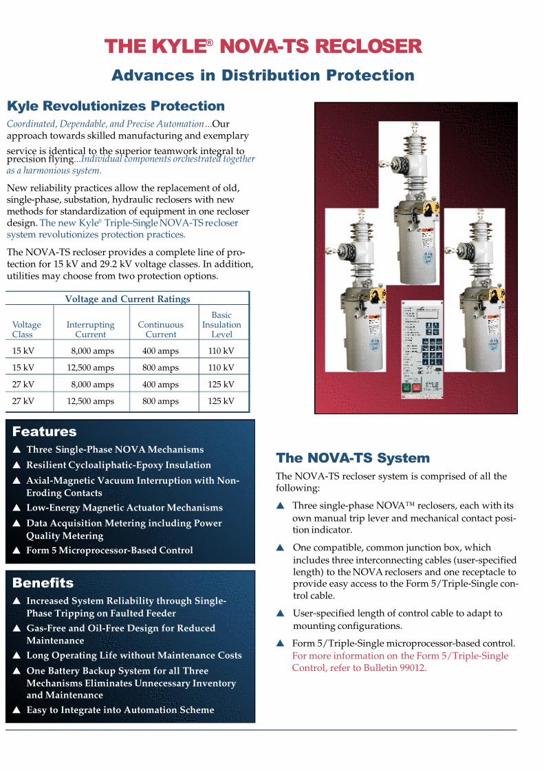
The NOVA-TS System
The NOVA-TS recloser system is comprised of all thefollowing:
Three single-phase NOVA™ reclosers, each with its
own manual trip lever and mechanical contact posi-tion indicator.
One compatible, common junction box, which
includes three interconnecting cables (user-specifiedlength) to the NOVA reclosers and one receptacle toprovide easy access to the Form 5/Triple-Single con-trol cable.
User-specified length of control cable to adapt to
mounting configurations.
Form 5/Triple-Single microprocessor-based control.
For more information on the Form 5/Triple-SingleControl, refer to Bulletin 99012.
Benefits
Increased System Reliability through Single-
Phase Tripping on Faulted Feeder
Gas-Free and Oil-Free Design for Reduced
Maintenance
Long Operating Life without Maintenance Costs
One Battery Backup System for all Three
Mechanisms Eliminates Unnecessary Inventoryand Maintenance
Easy to Integrate into Automation Scheme
Voltage and Current Ratings
BasicVoltage Interrupting Continuous InsulationClass Current Current Level
15 kV 8,000 amps 400 amps 110 kV
15 kV 12,500 amps 800 amps 110 kV
27 kV 8,000 amps 400 amps 125 kV
27 kV 12,500 amps 800 amps 125 kV
THE KYLE® NOVA-TS RECLOSER
Advances in Distribution Protection
7/27/2019 Cooper - Recloser - Type NOVA Brochure 2.pdf
http://slidepdf.com/reader/full/cooper-recloser-type-nova-brochure-2pdf 3/8
Multi-Mode Configuration
The NOVA-TS recloser has the versatility of three modesof operation. Activation is easily configured using theForm 5 interface software via a personal computer.
Three-Phase Trip, Three-Phase Lockout (MODE A)
All three phases simultaneously trip on an overcurrent,reclose, and sequence together.
Single-Phase Trip, Three-Phase Lockout (MODE B)Each individual phase will sense line current and only thephase corresponding to the faulted phase will trip. If anyone phase sequences to lockout, the other two phases alsoopen, eliminating permanent single phasing of three-phaseloads.
Single-Phase Trip, Single-Phase Lockout (MODE C)
Each individual phase trips and sequences to lockout inde-pendent of each other. This is primarily for residentialloads and/or where single-phasing of three-phase loads isprotected by other means.
Selectable Phase Operation
The front panel allows the user to manually open and closany phase independently without menu navigation.Included are direct LED’s to include the mode of operationplus open, close, and lockout LED’s on a per-phase basis.
The operator phase select keys are now convenientlydesigned to agree with the trip mode selected, eliminatingconfusion or special operations. For example, if three-phase lockout is set, select-phase keypads will be activated
simultaneously causing all three phases to trip or closewith the manual trip and close pushbuttons. In single-phase lockout, manual closing or tripping is achieved byselecting the desired phase to close or trip.
Overcurrent ProtectionPhase Operation
In MODE A, all three phases trip simultaneously with aphase overcurrent.
In MODES B and C, each phase is allowed to operate on apre-programmed sequence to lockout up to four times,
with the protection parameters (minimum trip values,time current curves, reclose intervals, reset times, andsequence of operation) the same for all three phases.
Ground Operation
In MODE A, all three phases trip simultaneously with aground overcurrent.
In MODES B and C, all faults above ground minimum tripand below phase minimum trip will result in three-phasetripping. Phase and ground also share the same sequenceposition. As the sequence position advances, the phaseand ground TCC’s advance.
For faults above phase minimum trip, the Form 5/Triple-Single control only trips on the phase(s) above minimumtrip operating on the phase or ground TCC, whichever isfaster. Each ground sequence and TCC timing willadvance with the appropriate phase sequence for faultsabove phase trip.
Dynamic Phase Tripping
A new configurable option for Mode C operation is avaiable to trip and lockout all three phases in the event of aphase-to-phase or three-phase fault. Normal operationoccurs per the programmed sequence, but protection is
enhanced by interrupting all three phases, even non-faulted phases. Should a phase-to-phase or three-phasefault be detected on the system, all three reclosers willtrip and lockout whenever any one phase sequences tolockout. Three-phase lockout occurs if a multiple phasefault is present as the recloser advances to lockout. Forexample, when there is a phase-to-phase fault, the controwill trip and lock out all three reclosers when any onephase sequences to lockout; thus avoiding any multi-phase energization from one phase.
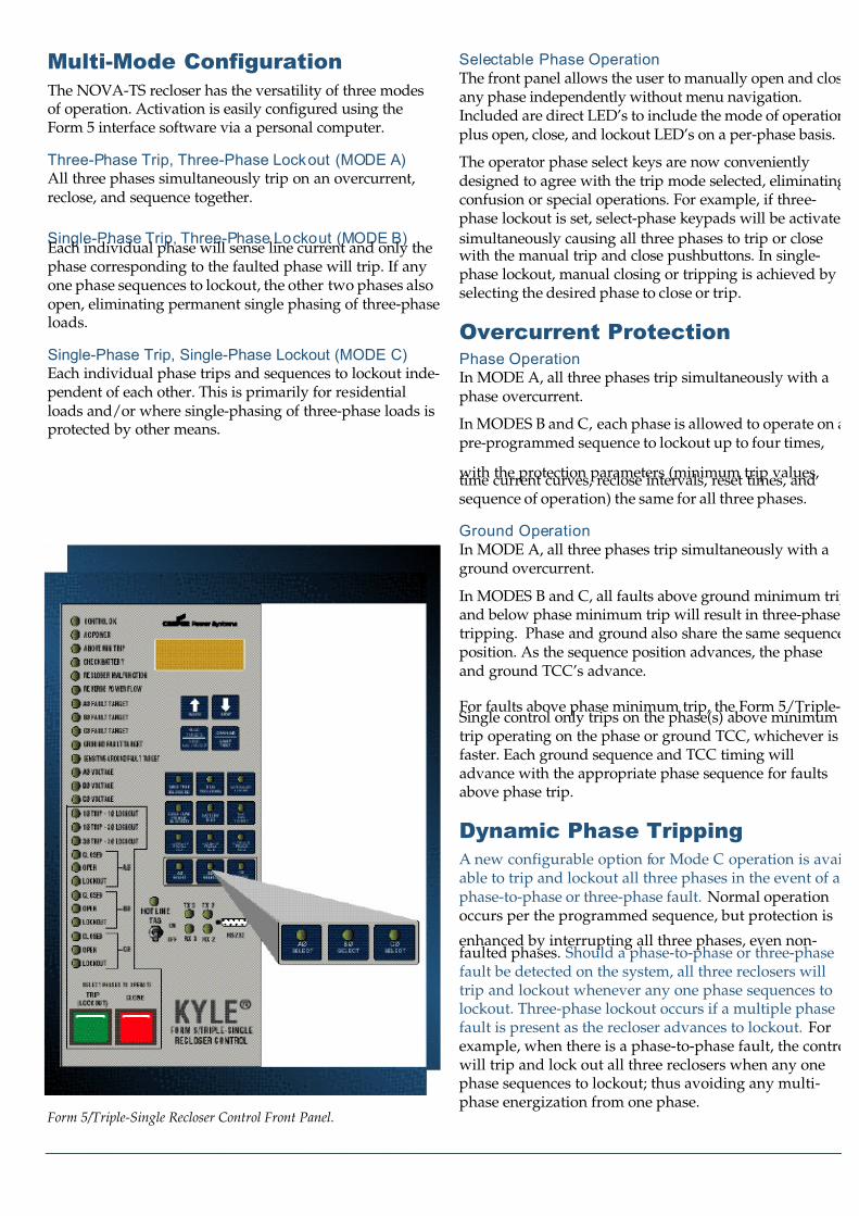
Form 5/Triple-Single Recloser Control Front Panel.
7/27/2019 Cooper - Recloser - Type NOVA Brochure 2.pdf
http://slidepdf.com/reader/full/cooper-recloser-type-nova-brochure-2pdf 4/8
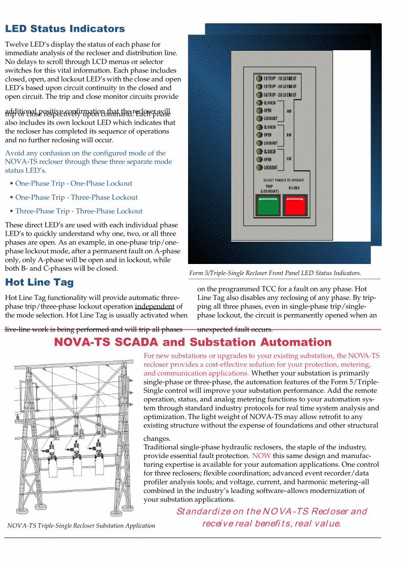
LED Status Indicators
Twelve LED’s display the status of each phase forimmediate analysis of the recloser and distribution line.No delays to scroll through LCD menus or selectorswitches for this vital information. Each phase includesclosed, open, and lockout LED’s with the close and openLED’s based upon circuit continuity in the closed andopen circuit. The trip and close monitor circuits provide
additional positive confirmation that the recloser willtrip or close respectively upon command. Each phasealso includes its own lockout LED which indicates thatthe recloser has completed its sequence of operationsand no further reclosing will occur.
Avoid any confusion on the configured mode of theNOVA-TS recloser through these three separate modestatus LED’s.
• One-Phase Trip - One-Phase Lockout
• One-Phase Trip - Three-Phase Lockout
• Three-Phase Trip - Three-Phase Lockout
These direct LED’s are used with each individual phaseLED’s to quickly understand why one, two, or all threephases are open. As an example, in one-phase trip/one-phase lockout mode, after a permanent fault on A-phaseonly, only A-phase will be open and in lockout, while both B- and C-phases will be closed.
Hot Line Tag
Hot Line Tag functionality will provide automatic three-phase trip/three-phase lockout operation independent of the mode selection. Hot Line Tag is usually activated when
live-line work is being performed and will trip all phases
on the programmed TCC for a fault on any phase. HotLine Tag also disables any reclosing of any phase. By trip-ping all three phases, even in single-phase trip/single-phase lockout, the circuit is permanently opened when an
unexpected fault occurs.
Form 5/Triple-Single Recloser Front Panel LED Status Indicators.
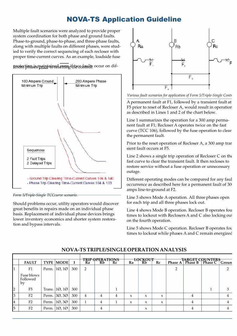
NOVA-TS SCADA and Substation Automation
NOVA-TS Triple-Single Recloser Substation Application
For new substations or upgrades to your existing substation, the NOVA-TSrecloser provides a cost-effective solution for your protection, metering,and communication applications. Whether your substation is primarilysingle-phase or three-phase, the automation features of the Form 5/Triple-Single control will improve your substation performance. Add the remoteoperation, status, and analog metering functions to your automation sys-tem through standard industry protocols for real time system analysis andoptimization. The light weight of NOVA-TS may allow retrofit to anyexisting structure without the expense of foundations and other structural
changes.Traditional single-phase hydraulic reclosers, the staple of the industry,provide essential fault protection. NOW this same design and manufac-turing expertise is available for your automation applications. One controlfor three reclosers; flexible coordination; advanced event recorder/dataprofiler analysis tools; and voltage, current, and harmonic metering–allcombined in the industry’s leading software–allows modernization of your substation applications.
Standardi ze on t he NOVA-TS Recl oser and
recei ve real benefi t s, real val ue.
7/27/2019 Cooper - Recloser - Type NOVA Brochure 2.pdf
http://slidepdf.com/reader/full/cooper-recloser-type-nova-brochure-2pdf 5/8
Multiple fault scenarios were analyzed to provide propersystem coordination for both phase and ground faults.Phase-to-ground, phase-to-phase, and three-phase faults,along with multiple faults on different phases, were stud-ied to verify the correct sequencing of each recloser withproper time-current curves. As an example, loadside fuse
protection is maintained even if two faults occur on dif-ferent phases prior to resetting the control.
Should problems occur, utility operators would discovergreat benefits in repairs made on an individual phase basis. Replacement of individual phase devices bringslower inventory economics and shorter system restora-tion and bypass intervals.
A permanent fault at F1, followed by a transient fault atF5 prior to reset of Recloser A, would result in operationas described in Lines 1 and 2 of the chart below.
Line 1 summarizes the operation for a 300 amp perma-nent fault at F1; Recloser A operates twice on the fast
curve (TCC 106), followed by the fuse operation to clearthe permanent fault.
Prior to the reset operation of Recloser A, a 300 amp transient fault occurs at F5.
Line 2 shows a single trip operation of Recloser C on thefast curve to clear the transient fault. It then recloses torestore service without a fuse operation or unnecessaryoutage.
Different operating modes can be compared for any fauloccurrence as described here for a permanent fault of 300amps line-to-ground at F2.
Line 3 shows Mode A operation. All three phases openfor each trip and all three phases lock out.
Line 4 shows Mode B operation. Recloser B operates foutimes to lockout with Reclosers A and C also locking outon the fourth operation.
Line 5 shows Mode C operation. Recloser B operates foutimes to lockout while phases A and C remain energized
NOVA-TS Application Guideline
Various fault scenarios for application of Form 5/Triple-Single Contr
Form 5/Triple-Single TCCcurve scenario.
TRIP OPERATIONS LOCKOUT TARGET COUNTERSFAULT TYPE MODE I Ra Rb Rc Ra Rb Rc Phase A Phase B Phase C Groun
1 F1 Perm. 1Ø, 1Ø 300 2 2 2
Fuse blowsFollowed by
2 F5 Trans. 1Ø, 1Ø 300 1 1 3
3 F2 Perm. 3Ø, 3Ø 300 4 4 4 x x x 4 4
4 F2 Perm. 1Ø, 3Ø 300 1 4 1 x x x 4 4
5 F2 Perm. 1Ø, 1Ø 300 4 x 4 4
NOVA-TS TRIPLE/SINGLE OPERATION ANALYSIS
7/27/2019 Cooper - Recloser - Type NOVA Brochure 2.pdf
http://slidepdf.com/reader/full/cooper-recloser-type-nova-brochure-2pdf 6/8
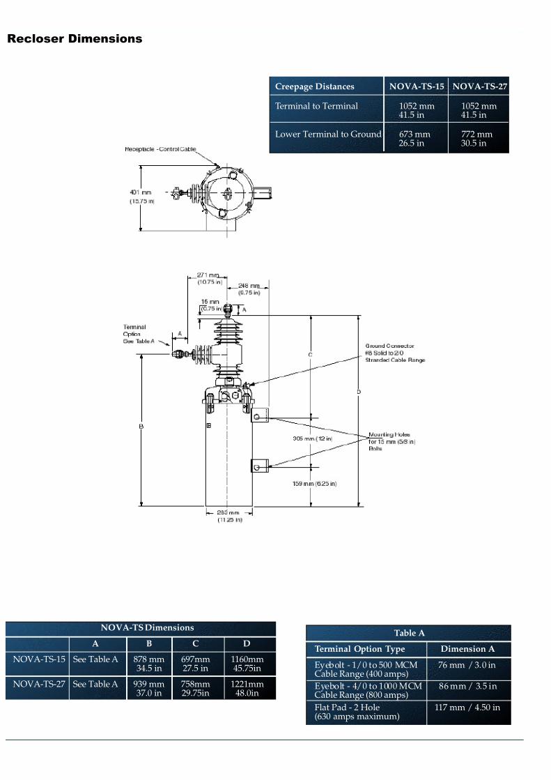
Recloser Dimensions
NOVA-TS Dimensions
A B C D
NOVA-TS-15 See Table A 878 mm 697mm 1160mm34.5 in 27.5 in 45.75in
NOVA-TS-27 See Table A 939 mm 758mm 1221mm37.0 in 29.75in 48.0in
Table A
Terminal Option Type Dimension A
Eyebolt - 1/0 to 500 MCM 76 mm / 3.0 inCable Range (400 amps)
Eyebolt - 4/0 to 1000 MCM 86 mm / 3.5 inCable Range (800 amps)
Flat Pad - 2 Hole 117 mm / 4.50 in(630 amps maximum)
Creepage Distances NOVA-TS-15 NOVA-TS-27
Terminal to Terminal 1052 mm 1052 mm41.5 in 41.5 in
Lower Terminal to Ground 673 mm 772 mm26.5 in 30.5 in
7/27/2019 Cooper - Recloser - Type NOVA Brochure 2.pdf
http://slidepdf.com/reader/full/cooper-recloser-type-nova-brochure-2pdf 7/8
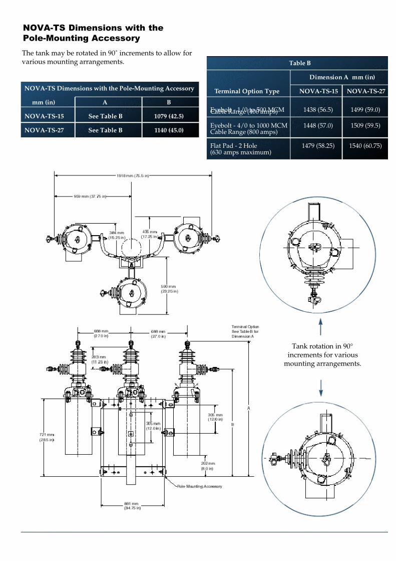
NOVA-TS Dimensions with the
Pole-Mounting Accessory
NOVA-TS Dimensions with the Pole-Mounting Accessory
mm (in) A B
NOVA-TS-15 See Table B 1079 (42.5)
NOVA-TS-27 See Table B 1140 (45.0)
The tank may be rotated in 90˚ increments to allow forvarious mounting arrangements.
mm (in)
Tank rotation in 90°increments for various
mounting arrangements.
Table B
Dimension A mm (in)
Terminal Option Type NOVA-TS-15 NOVA-TS-27
Eyebolt - 1/0 to 500 MCM 1438 (56.5) 1499 (59.0)Cable Range (400 amps)
Eyebolt - 4/0 to 1000 MCM 1448 (57.0) 1509 (59.5)Cable Range (800 amps)
Flat Pad - 2 Hole 1479 (58.25) 1540 (60.75)(630 amps maximum)
7/27/2019 Cooper - Recloser - Type NOVA Brochure 2.pdf
http://slidepdf.com/reader/full/cooper-recloser-type-nova-brochure-2pdf 8/8
Kxx
P.O. Box 1640Waukesha, WI 53187www.cooperpower.com
2001 Cooper Industries, Inc.
Kyle ® is a registered trademark of Cooper Industries, Inc.NOVA™ is a trademark of Cooper Industries, Inc.
Bulletin 99015 • January 2001 • Supersedes 5/00
The Quality System atCooper Power Systems,
Kyle Distribution Switchgear isISO 9001 certified.
NOVA-TS Recloser Accessories•2-Hole Flat Pad Terminal - 630 Amp maximum
•Aluminized Steel Tank
•3-Stage Auxiliary Switch
•Auxiliary Switch Junction Box/Cable
•Crossarm-Mounting Hanger
•Pole-Mounting Hanger•Arrester-Mounting Brackets
•Substation-Mounting Bracket
•Wildlife Restraint Equipment
Form 5/Triple-Single Electronic
Recloser Control Accessories•Automation System Packages
•Input Power Receptacles
•Protocol 2179
•Protocol DNP3.0
•Fiber-Optic/RS-232 Interface Board
•Fused, 120 Vac, 3-Wire Polarized GFI ConvenienceOutlet
•Stainless Steel Cabinet
•Universal Device Protection including Switch Mode
Division Headquarters2300 Badger DriveWaukesha, Wisconsin 53188 USA
Phone: 1-262-524-3300Fax: 1-262-524-3319
International OfficesMiami, Florida USAPhone: 1-305-477-9400
Fax: 1-305-477-9414
Athens, GreecePhone: 011-30-1-964-6332Fax: 011-30-1-964-6336
Sydney, AustraliaPhone: 011-61-2-9683-1122Fax: 011-61-2-9683-6840
Taipei, TaiwanPhone: 011-886-2-2758-4530Fax: 011-886-2-2758-4535
SingaporePhone: 011-65-298-3191Fax: 011-65-298-0559