Embed Size (px)
Citation preview
CONVENTIONAL MACHINING PROCESSES AND MACHINE TOOLS
Module-IV
Turning
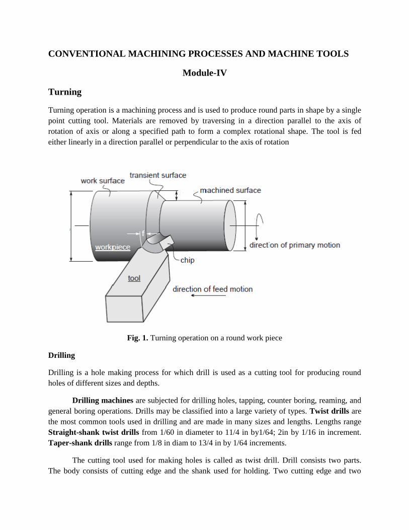
Turning operation is a machining process and is used to produce round parts in shape by a single
point cutting tool. Materials are removed by traversing in a direction parallel to the axis of
rotation of axis or along a specified path to form a complex rotational shape. The tool is fed
either linearly in a direction parallel or perpendicular to the axis of rotation
Fig. 1. Turning operation on a round work piece
Drilling
Drilling is a hole making process for which drill is used as a cutting tool for producing round
holes of different sizes and depths.
Drilling machines are subjected for drilling holes, tapping, counter boring, reaming, and
general boring operations. Drills may be classified into a large variety of types. Twist drills are
the most common tools used in drilling and are made in many sizes and lengths. Lengths range
Straight-shank twist drills from 1/60 in diameter to 11/4 in by1/64; 2in by 1/16 in increment.
Taper-shank drills range from 1/8 in diam to 13/4 in by 1/64 increments.
The cutting tool used for making holes is called as twist drill. Drill consists two parts.
The body consists of cutting edge and the shank used for holding. Two cutting edge and two
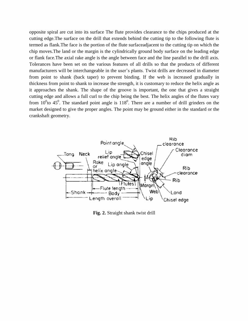
opposite spiral are cut into its surface The flute provides clearance to the chips produced at the
cutting edge.The surface on the drill that extends behind the cutting tip to the following flute is
termed as flank.The face is the portion of the flute surfaceadjacent to the cutting tip on which the
chip moves.The land or the margin is the cylindrically ground body surface on the leading edge
or flank face.The axial rake angle is the angle between face and the line parallel to the drill axis.
Tolerances have been set on the various features of all drills so that the products of different
manufacturers will be interchangeable in the user’s plants. Twist drills are decreased in diameter
from point to shank (back taper) to prevent binding. If the web is increased gradually in
thickness from point to shank to increase the strength, it is customary to reduce the helix angle as
it approaches the shank. The shape of the groove is important, the one that gives a straight
cutting edge and allows a full curl to the chip being the best. The helix angles of the flutes vary
from 100to 45
0. The standard point angle is 118
0. There are a number of drill grinders on the
market designed to give the proper angles. The point may be ground either in the standard or the
crankshaft geometry.
Fig. 2. Straight shank twist drill
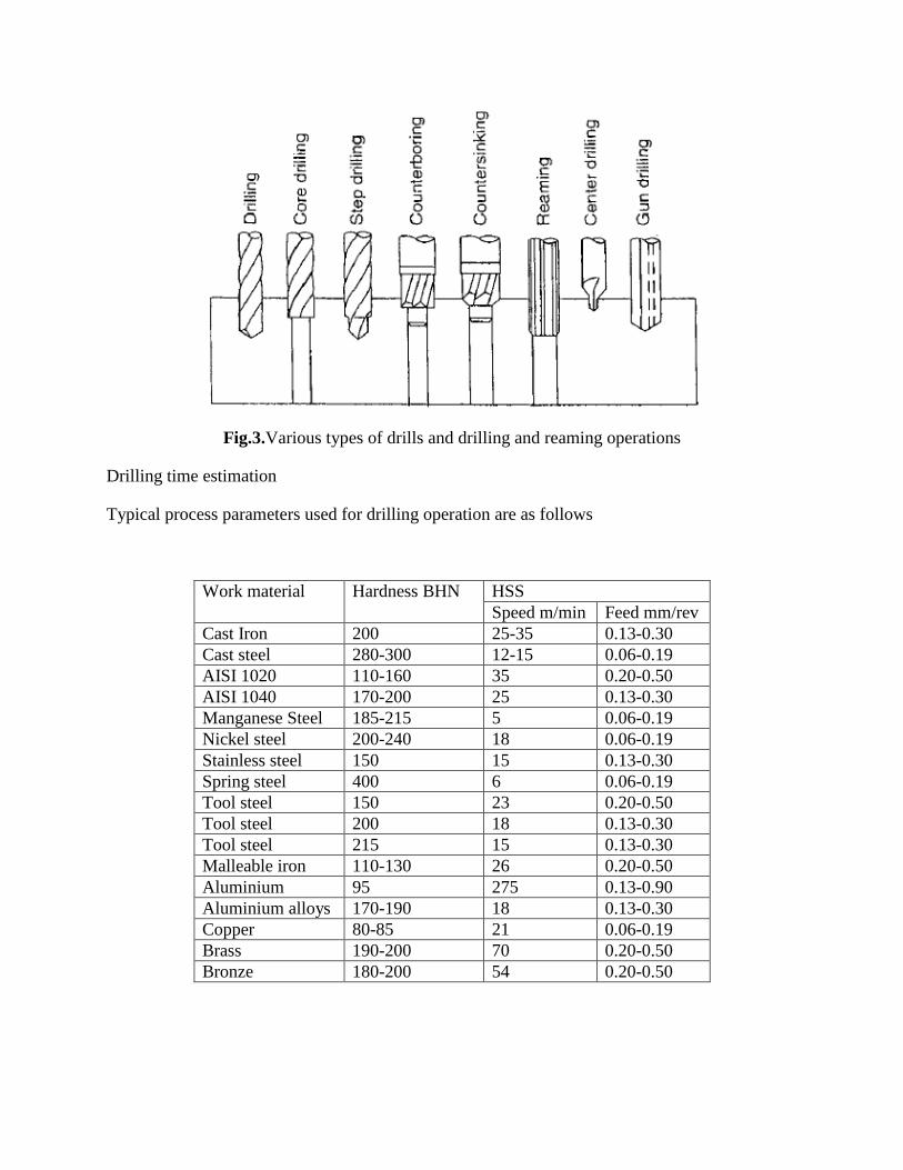
Fig.3.Various types of drills and drilling and reaming operations
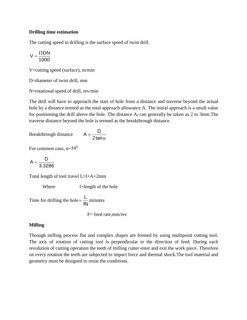
Drilling time estimation
Typical process parameters used for drilling operation are as follows
Work material Hardness BHN HSS
Speed m/min Feed mm/rev
Cast Iron 200 25-35 0.13-0.30
Cast steel 280-300 12-15 0.06-0.19
AISI 1020 110-160 35 0.20-0.50
AISI 1040 170-200 25 0.13-0.30
Manganese Steel 185-215 5 0.06-0.19
Nickel steel 200-240 18 0.06-0.19
Stainless steel 150 15 0.13-0.30
Spring steel 400 6 0.06-0.19
Tool steel 150 23 0.20-0.50
Tool steel 200 18 0.13-0.30
Tool steel 215 15 0.13-0.30
Malleable iron 110-130 26 0.20-0.50
Aluminium 95 275 0.13-0.90
Aluminium alloys 170-190 18 0.13-0.30
Copper 80-85 21 0.06-0.19
Brass 190-200 70 0.20-0.50
Bronze 180-200 54 0.20-0.50
Drilling time estimation
The cutting speed in drilling is the surface speed of twist drill.
1000
DNV
V=cutting speed (surface), m/min
D=diameter of twist drill, mm
N=rotational speed of drill, rev/min
The drill will have to approach the start of hole from a distance and traverse beyond the actual
hole by a distance termed as the total approach allowance A. The initial approach is a small value
for positioning the drill above the hole. The distance AI can generally be taken as 2 to 3mm.The
traverse distance beyond the hole is termed as the breakthrough distance.
Breakthrough distance
tan2
DA
For common case, α=590
3286.3
DA
Total length of tool travel L=l+A+2mm
Where l=length of the hole
Time for drilling the holefN
L minutes
F= feed rate,mm/rev
Milling
Through milling process flat and complex shapes are formed by using multipoint cutting tool.
The axis of rotation of cutting tool is perpendicular to the direction of feed. During each
revolution of cutting operation the teeth of milling cutter enter and exit the work piece. Therefore
on every rotation the teeth are subjected to impact force and thermal shock.The tool material and
geometry must be designed to resist the conditions.
TYPES OF MILLING MACHINE
To satisfy the variety of requirement, milling machine comes in a number of ways, sizes and
varieties.
a) Knee and column type
b) Horizontal
c) Vertical
d) Universal
e) Turret type
These are the general purpose milling machine, which have a high degree of flexibility and
employed for all types of works, including batch manufacturing.
f) Production (bed) type
g) Simplex
h) Duplex
Triplex these machines are generally meant for regular production involving large batch sizes.
The flexibility is relatively less in these machines than suitable for productivity enhancement.
i) Plano millers- these machines are used only for very large work-piece involving table
travels in metres.
j) Special type
Rotary table
Drum type
Copy milling (die sinking machine)
Keyway milling machines
Spline milling machine
These machines are of a special facilities to suit specific applications that catered by the other
classes of milling machines.
KNEE AND COLUMN MILLING MACHINE
The knee and column type milling machine is the most commonly used machine in view of its
flexibility and easier setup. The knee houses the feed mechanism and mounts the saddle and
table. The table basically has the t-slots running along the x-axis for the purpose of work holding.
The table moves along the x-axis on the saddle while the saddle moves along the y-axis on the
guideways provided on the knee. The feed is provided either manually by hand wheel or
connected for automatic by the lead screw, which in turn is coupled to the main spindle drive.
The knee can move up and down in a dovetail provided on the column.
Milling machines are generally specified based on the following features.
Size of the table, which specifies the actual working area on the table and relates to the
maximum size of the work-piece that can be accommodated.
Amount of table travel which gives the maximum axis movement that is possible.
Horse power of the spindle, which actually specifies the power of the spindle motor used.
Smaller machines may come with 1 to 3 hp while the production machines may go from
10 to 50 hp.
Another type of knee and column milling machine possible is the vertical-axis type. Most of the
construction is very is very similar to the horizontal-axis type except the spindle type and
location. The spindle is located in the vertical direction and is suitable for using the shank-
mounted milling cutter such as end mills. In view of the location of the tool, the setting up of the
work-piece and observing the machining operation is more convenient.
The universal machine is suitable for milling spur and helical gears, as well as worm gears and
cam as it can be swivelled in a horizontal plane about 45 degree to either left or right.
BED-TYPE MILLING MACHINE
These are made more rugged and consequently are capable of removing more material without
any chatter. Here the table is directly mounted on the bed and is provided with only the
longitudinal motion. The spindle will be moving along with the column to provide the cutting
action.
Simplex machines are the ones with only one spindle head while duplex machines have two
spindles.
Milling operations are of two types
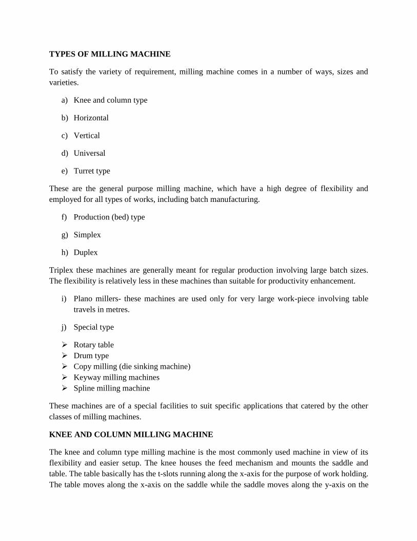
Down milling
Here the cutter direction is same direction as the motion of the work piece being fed.
Up milling
Here work piece is moving towards the cutter, opposing the cutter direction of
rotation.Surface finish is better in case of down milling,but the stress load on the teeth is
abrupt that may damage the cutter.
Fig.4. Schematic depiction of down milling (a) and up milling (b) operations
Advantages
1. Suited to machine-thin and hard to hold parts
2. Work need not be clamped tightly
3. Consistent parallelism and size may be maintained particularly on the thin parts
4. Used where break out of the edge of the work piece could not be tolerated.
5. Requires up to 20% less power to cut.
6. Used when cutting off stock or when milling deep, thin slots.
Disadvantages
1. Cannot be used unless the machine has a backlash eliminator and the table jibs have been
tightened
2. Cannot be used for machining castings or hot rolled steel, since hard outer scale will
damage the cutter.
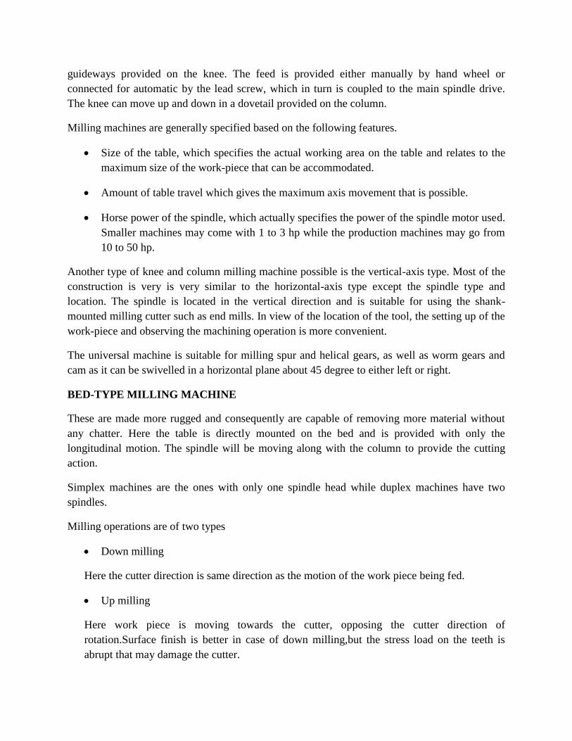
Grinding
Grinding is the most common form of abrasive machining. It is a material cutting process that
engages an abrasive tool whose cutting elements are grains of abrasive material known as grit.
These grits are characterized by sharp cutting points, high hot hardness, chemical stability and
wear resistance. The grits are held together by a suitable bonding material to give shape of an
abrasive tool. Grinding machine is employed to obtain high accuracy along with very high class
of surface finish on the work piece. However, advent of new generation of grinding wheels and
grinding machines, characterized by their rigidity, power and speed enables one to go for high
efficiency deep grinding (often called as abrasive milling) of not only hardened material but also
ductile materials.
Grain size
Compared to the normal cutting tool, the abrasive used in grinding wheels are relatively small.
The size of an abrasive grain or more generally called grit is identified by a number which is
based on the sieve size used. This would vary from a very coarse size of 6 to 8 to a super fine
size of 500 or 600. Sieve number is specified in terms of the number of opening per square inch.
The surface finish generated would depend upon grain size used. The fine grain will take a very
small depth of cut and hence a better surface finish is produced. Fine grains generate less heat are
good for faster material removal. Fine grains are used for making the form grinding wheels.
Coarse grains are good for higher material removal rates. These have better friability and as a
result are not good for intermittent where they are likely to chip easily.
Bonded Abrasives
• A composite of the abrasive powder and a matrix
• Bonding material can be glass, resin, rubber.
• Can be solid discs (grinding wheel) or bonded to paper/cloth which is then stuck to a backing
disc.
The most commonly used bond materials are
Vitrified
Silicate
Synthetic resin
Rubber
Shellac
Metal
CENTRE-LESS GRINDING
It is used to grind cylindrical work-piece without actually fixing the work-piece using centres or
a chuck, due to which the work rotation is not provided separately.
Its process consists of wheel, one large grinding wheel and another smaller regulating wheel. The
work-piece is supported by the rest blade and held against the regulating wheel by the grinding
force which is mounted at an angle to the plane of grinding wheel. The regulating wheel is
generally a rubber or resinoid bonded wheel with wide face. The axial feed of the work-piece is
controlled by the angle of tilt of the regulating wheel. Typical work speeds are about 10 to 50
m/mm.
There are three types of centre-less grinding operations possible. They are:
a) Through feed centre-less grinding.
b) In feed centre-less, the grinding is done by plunge feeding so that any form surface can
be produced. This is useful if the work-piece has an obstruction which will not allow it to
be traversed past the grinding wheel. The obstruction could be a shoulder, head, round
form, etc.
c) End feed centre-less grinding, where tapered work-piece can be machined.
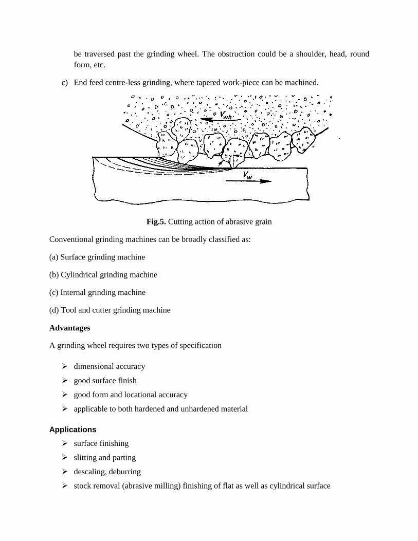
Fig.5. Cutting action of abrasive grain
Conventional grinding machines can be broadly classified as:
(a) Surface grinding machine
(b) Cylindrical grinding machine
(c) Internal grinding machine
(d) Tool and cutter grinding machine
Advantages
A grinding wheel requires two types of specification
dimensional accuracy
good surface finish
good form and locational accuracy
applicable to both hardened and unhardened material
Applications
surface finishing
slitting and parting
descaling, deburring
stock removal (abrasive milling) finishing of flat as well as cylindrical surface
grinding of tools and cutters and re sharpening of the same.
Conventionally grinding is characterized as low material removal process capable of providing
both high accuracy and high finish. However, advent of advanced grinding machines and
grinding wheels has elevated the status of grinding to abrasive machining where high accuracy
and surface finishas well as high material removal rate can be achieved even on an unhardened
material
Broaching
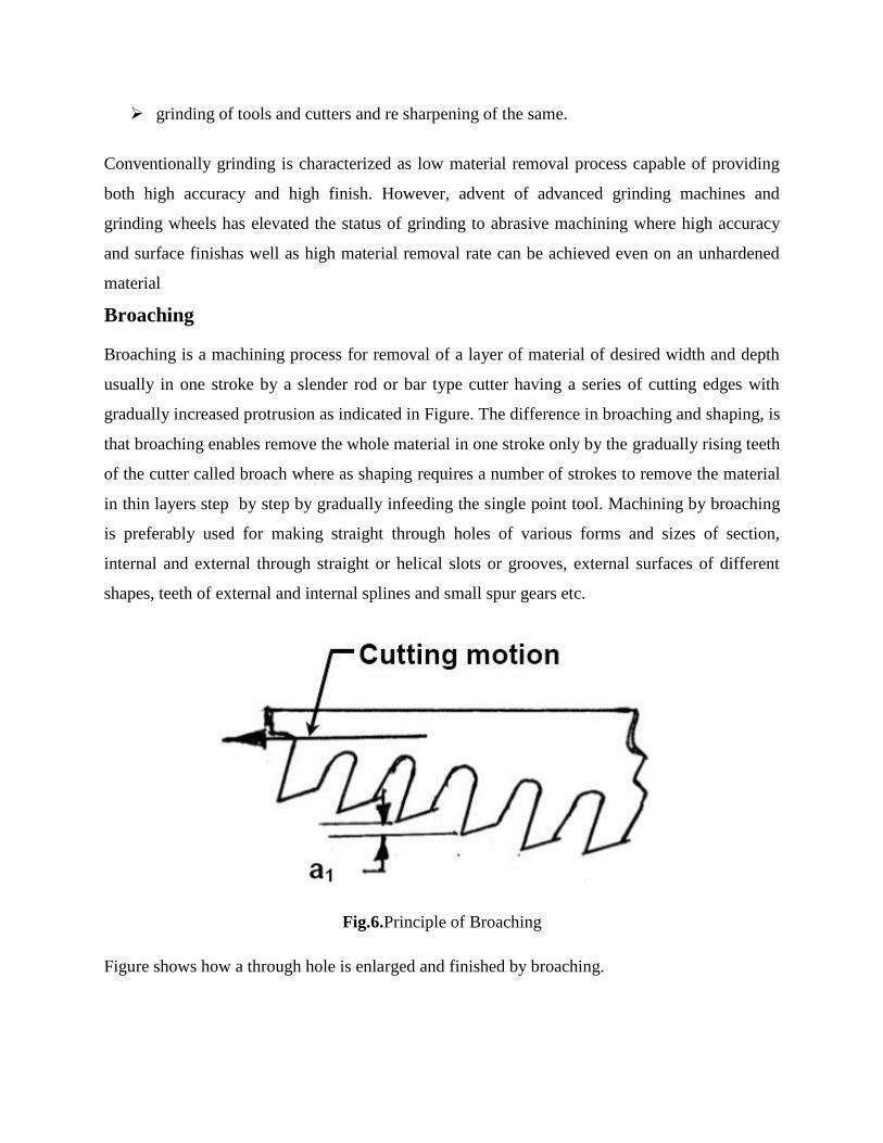
Broaching is a machining process for removal of a layer of material of desired width and depth
usually in one stroke by a slender rod or bar type cutter having a series of cutting edges with
gradually increased protrusion as indicated in Figure. The difference in broaching and shaping, is
that broaching enables remove the whole material in one stroke only by the gradually rising teeth
of the cutter called broach where as shaping requires a number of strokes to remove the material
in thin layers step by step by gradually infeeding the single point tool. Machining by broaching
is preferably used for making straight through holes of various forms and sizes of section,
internal and external through straight or helical slots or grooves, external surfaces of different
shapes, teeth of external and internal splines and small spur gears etc.
Fig.6.Principle of Broaching
Figure shows how a through hole is enlarged and finished by broaching.
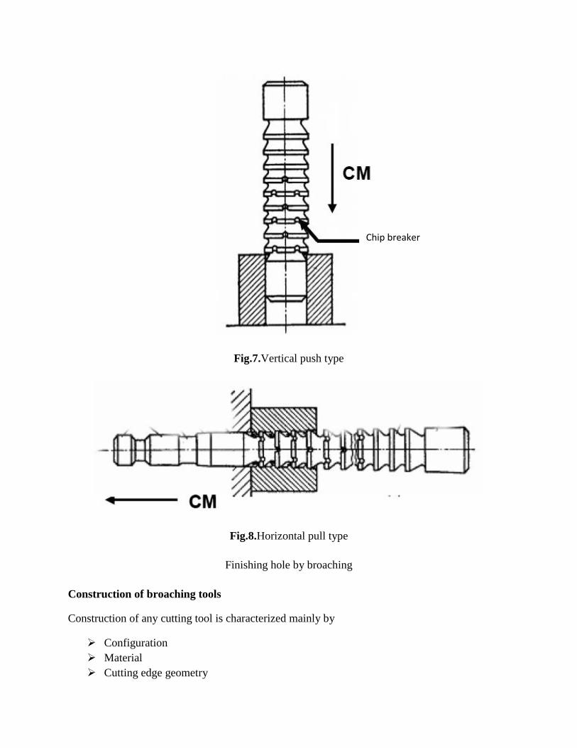
Fig.7.Vertical push type
Fig.8.Horizontal pull type
Finishing hole by broaching
Construction of broaching tools
Construction of any cutting tool is characterized mainly by
Configuration
Material
Cutting edge geometry
Chip breaker
Both pull and push type broaches are made in the form of slender rods or bars of varying
section having along its length one or more rows of cutting teeth with increasing height (and
width occasionally). Push type broaches are subjected to compressive load and hence are
made shorter in length to avoid buckling.
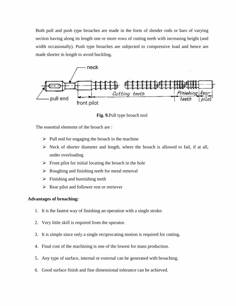
Fig. 9.Pull type broach tool
The essential elements of the broach are :
Pull end for engaging the broach in the machine
Neck of shorter diameter and length, where the broach is allowed to fail, if at all,
under overloading
Front pilot for initial locating the broach in the hole
Roughing and finishing teeth for metal removal
Finishing and burnishing teeth
Rear pilot and follower rest or retriever
Advantages of broaching:
1. It is the fastest way of finishing an operation with a single stroke.
2. Very little skill is required from the operator.
3. It is simple since only a single reciprocating motion is required for cutting.
4. Final cost of the machining is one of the lowest for mass production.
5. Any type of surface, internal or external can be generated with broaching.
6. Good surface finish and fine dimensional tolerance can be achieved.
Limitations of broaching:
1. Custom made broaches are very expensive and hence generally used for very large
volume production.
2. The lead time for manufacturing is more for custom designed broaches.
3. A broach can be designed and used for a specific application.
4. As it is a very heavy metal removal operation, it requires that work-piece is rigid and
capable of withstanding the large forces.
It can only be carried out on the work-piece whose geometry is such that there is no inference for
broach movement for the cutting
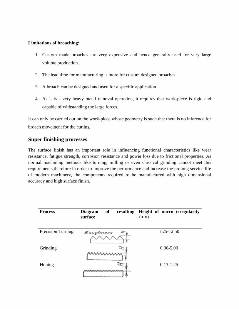
Super finishing processes
The surface finish has an important role in influencing functional characteristics like wear
resistance, fatigue strength, corrosion resistance and power loss due to frictional properties. As
normal machining methods like turning, milling or even classical grinding cannot meet this
requirements,therefore in order to improve the performance and increase the prolong service life
of modern machinery, the components required to be manufactured with high dimensional
accuracy and high surface finish.
Process Diagram of resulting
surface
Height of micro irregularity
)m(
Precision Turning
1.25-12.50
Grinding
0.90-5.00
Honing
0.13-1.25
Lapping
0.08-0.25
Superfinishing
0.01-0.25
Lapping, honing, polishing, burnishing are some of the super finishing processes that are
employed to achieve above properties.
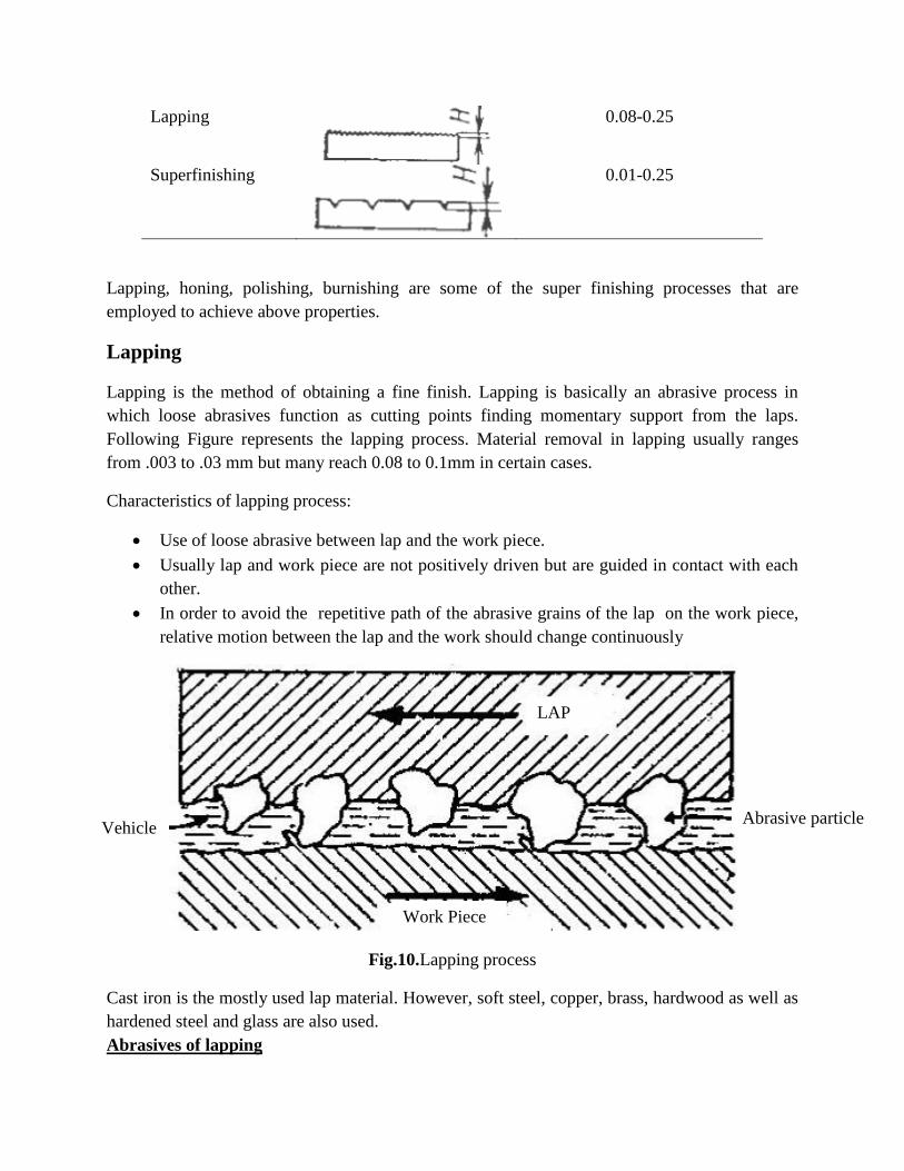
Lapping
Lapping is the method of obtaining a fine finish. Lapping is basically an abrasive process in
which loose abrasives function as cutting points finding momentary support from the laps.
Following Figure represents the lapping process. Material removal in lapping usually ranges
from .003 to .03 mm but many reach 0.08 to 0.1mm in certain cases.
Characteristics of lapping process:
Use of loose abrasive between lap and the work piece.
Usually lap and work piece are not positively driven but are guided in contact with each
other.
In order to avoid the repetitive path of the abrasive grains of the lap on the work piece,
relative motion between the lap and the work should change continuously
Fig.10.Lapping process
Cast iron is the mostly used lap material. However, soft steel, copper, brass, hardwood as well as
hardened steel and glass are also used.
Abrasives of lapping
LAP
Work Piece
Abrasive particle Vehicle
Al2O
3 and SiC, grain size 5~100μm
Cr2O
3, grain size 1~2 μm
B4C
3, grain size 5-60 μm
Diamond, grain size 0.5~5 V
Vehicle materials for lapping
Machine oil
Rape oil
grease
Technical parameters affecting lapping processes
unit pressure
grain size of abrasive
concentration of abrasive in the vehicle
lapping speed
Honing
Honing is a finishing process, in which a tool called hone carries out a combined rotary and
reciprocating motion while the work piece does not perform any working motion. The honing
stones are held against the work piece with controlled light pressure. Honing is generally done on
internal cylindrical surface, such as automobile cylindrical walls.
Following assumptions are considered during honing processes.
Honing stones should not leave the work surface.
Stroke length must cover the entire work length.
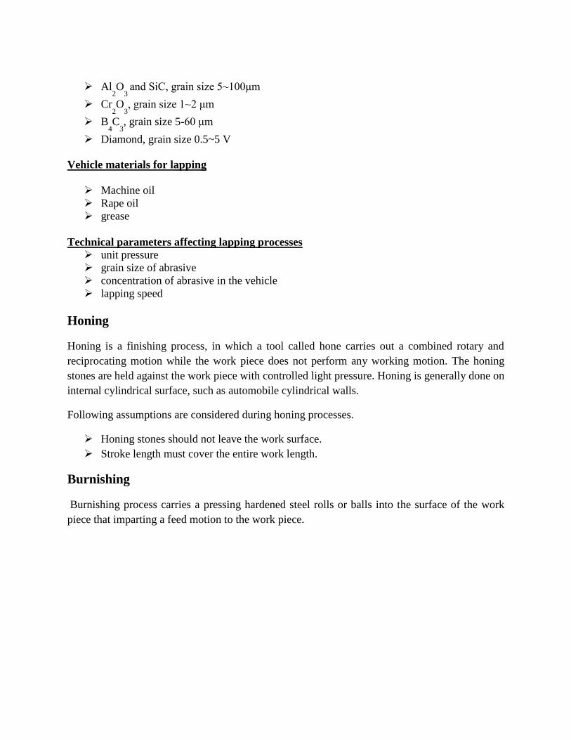
Burnishing
Burnishing process carries a pressing hardened steel rolls or balls into the surface of the work
piece that imparting a feed motion to the work piece.
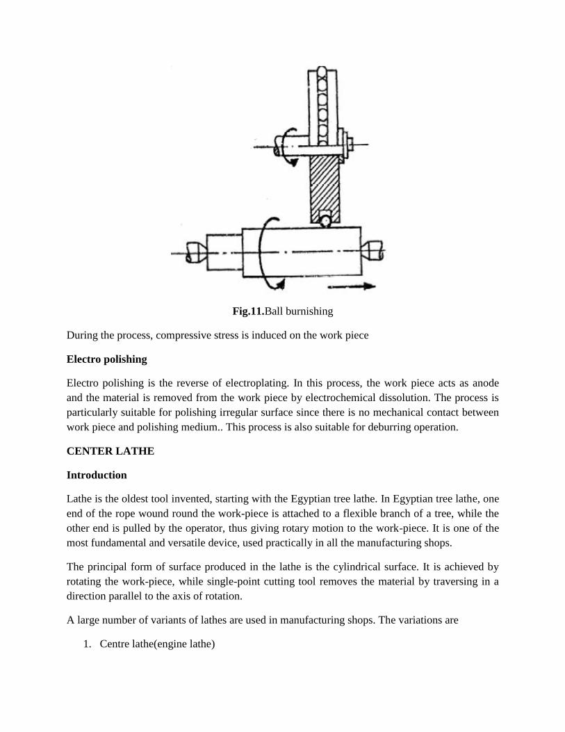
Fig.11.Ball burnishing
During the process, compressive stress is induced on the work piece
Electro polishing
Electro polishing is the reverse of electroplating. In this process, the work piece acts as anode
and the material is removed from the work piece by electrochemical dissolution. The process is
particularly suitable for polishing irregular surface since there is no mechanical contact between
work piece and polishing medium.. This process is also suitable for deburring operation.
CENTER LATHE
Introduction
Lathe is the oldest tool invented, starting with the Egyptian tree lathe. In Egyptian tree lathe, one
end of the rope wound round the work-piece is attached to a flexible branch of a tree, while the
other end is pulled by the operator, thus giving rotary motion to the work-piece. It is one of the
most fundamental and versatile device, used practically in all the manufacturing shops.
The principal form of surface produced in the lathe is the cylindrical surface. It is achieved by
rotating the work-piece, while single-point cutting tool removes the material by traversing in a
direction parallel to the axis of rotation.
A large number of variants of lathes are used in manufacturing shops. The variations are
1. Centre lathe(engine lathe)
Bench lathe
2. Tool room lathe
3. Special purpose lathes
Copying lathe
Gap bed lathe
Hollow spindle lathe
4. Capstan and turret lathe
5. Automatic lathe
The centre lathe (commonly used), which derives its name from the way a work-piece is clamped
by centre in a lathe, though this is not the only way in which the job is mounted.
The tool room lathe is generally meant for tool making where accuracy is of higher priority.
Thus, the machine would have a higher range of speeds and feeds along with greater rigidity
with a larger range of accessories and attachments.
The special purpose lathes are developed from the centre lathe to crater to special forms of
application, which cannot be handled by the conventional centre lathe.
Capstan and turret lathes are used for very special application as they have high rate of
production.
CONTRUCTIONAL FEATURES OF A CENTRE LATHE
The major elements present in the lathe are:
1. The headstock - fixed towards the left end of the bed and houses the power source, power
transmission, gear box, and spindle)
2. The main gear box – provides the necessary spindle speed as per the range of materials to
be turned. The feed gear box provides the various feed rates and thread cutting ranges.
3. The tailstock – fixed towards the right end of the bed. It has a tailstock spindle to locate
the long components by the use of centres. It moves on inner guideways to accommodate
the different lengths of work-piece. Its also serves the purpose of holding tools, for
making and finishing holes in the components that are located in the line with the axis of
rotation.
4. The carriage – it provides the necessary longitudinal motion to the cutting tool to
generate the necessary surface. This also houses the cross slide (to provide cross feed to
cutting tool) and compound slide (to provide auxiliary motion to cutting tool).
5. Lead screw – it communicates the motion from the spindle motor to the carriage. It
engages with the carriage through a half nut. It can also be used for feeding the cutting
tool in a direction parallel to the axis of rotation, but it is sparingly used for thread
cutting, such that it maintains its accuracy.
6. Feed rod – it is used for routine feeding of cutting tools.
LATHE SPECIFICATION
There are a number of factors that should be specified to fully describes a lathe machine. They
are:
Distance between centres - specifies the maximum length of the job that can be turned.
Swing over the bed- specifies the maximum diameter of the job that can be turned.
Swing over the cross-slide – specifies the maximum diameter of the job that can be turn
with the job across the cross-slide.
Horse Power of motor.
Cutting speed range
Feed range.
Screw cutting capacity
Spindle nose diameter and hole size
AIDS FOR SUPPORT AND LOCATION
The work holding devices normally used should have the following provisions:
Suitable location
Effective clamping
Support
CHUCK is the most common form of work holding device used in lathe. It is available with
varying number of jaws. Three jaw chuck or self-centring chuck is the most common one of all.
Its main advantage is the quick way in which the typical round job is centred. All the three jaws
would be meshing with the flat scroll plate. Rotating the scroll plate through a bevel pinion
would move all the three jaws radially, inward or outward, the same amount. Thus, the jaws
would be able to centre any job whose external locating surface is cylindrical or symmetrical. It
has limitation in terms of gripping force and accuracy.
The independent jaw chuck has four jaws, which can be moved in their slots independent of each
other. Hence better accuracy can be maintained. But fixturing of a component is more time
consuming. Its jaws can be reversed to clamp larger diameter work-piece.
The three-jaw and four-jaw chucks are suitable for short components. However, in case of long
components support at one end is not sufficient, as is done in case of chucks, would make it to
deflect under the influence of the cutting force. In such cases, the long work-piece is held in
between the centres. The work-piece is provided with a centre hole. Through this centre hole, the
centres mounted in the spindle and the tailstock would rigidly locate the axis of work-piece. To
transmit motion to the work-piece from the spindle a carrier plate and a dog is used. The centre
located in the spindle is termed as live centre, while that in the tailstock is termed as dead centre.
The shank of the centre is generally finished with a more taper which fits into the tapered hole of
the spindle or tailstock.
There is a relative motion between the work-piece and the dead centre (live centre only rotates
with the work-piece). As a result a large amount of heat is generated. For this, a revolving centre
is used, that is mounted in roller bearing and thus rotates freely.
Some precautions to be observed during the use of centres are:
The centre hole in the work must be clean and smooth and have an angle of 60 degree
bearing surface, large enough to be consistent with the diameter of the work. For heavier
work, this may be made 75 degree or 90 degrees.
The bearing must take place on the counter sunk surface, and not at the bottom of the
drilled hole.
For odd shaped components, a faceplate is more widely used, where the locating and clamping
surface need not be circular. There are radial slots on the plate, for the purpose of locating the
component and clamping by means of any standard clamps. There is the possibility of mass
unbalance. A balancing mass would therefore be provided. Sometimes angle plates along with
the faceplate may have to be used for typical components, where the locating surface is
perpendicular to the plane of the faceplate.
Collet provides good clamping accuracy with very little time required for clamping and
unclamping. It has the holding part, which is slit along the length at a number of points along the
circumference. When the uniform pressure is applied along the circumference of the sleeve,
these segments would elastically deflect and clamp the component located inside. Tis clamping
method is very accurate.
OPERATION PERFORMED IN A CENTRE LATHE
Based on the various settings that are possible, following are the types of operations performed
of centre lathe:
TURNING- Here cylindrical surfaces are generated. In this case, the work held in the
spindle is rotated while the tool is fed past the work-piece in a direction parallel to the
axis of rotation.
FACING- It is an operation generating flat surfaces. The feed given here is perpendicular
to the axis of revolution and the radius of work-piece at the contact point varies
continuously as the tool approaches the centre and hence varies the resulting cutting
speed.
KNURLING OPERATION- It is a metal operating operation. In this, a knurling tool
having the requisite serration is forced on to the work-piece thus deforming the top layer.
PARTING OPERATION- parting and grooving are similar operations. In this a flat
nosed tool would plunge cut the work-piece with a feeding a direction perpendicular to
the axis of revolution. It is used for cutting off the part from the parent material or to get a
rectangular groove.
DRILLING- It is the operation of making cylindrical holes into the solid material. A
twist drill is held in the quill of the tailstock, and is fed into the rotating work-piece by
feeding the tailstock quill. This operation is limited to holes through the axis of rotation
of the work-piece.
BORING- It is the operation for enlarging the holes already made by a single point
boring tool termed as boring bar.
5- SPECIAL- PURPOSE LATHES
The main limitations of centre lathe are:
The setting time for the job in terms of holding the job is large.
Only one tool can be used in the normal course. Sometimes the conventional tool post
can be replaced by a square tool post with four tools.
The idle times involved in the setting and movement of tools between the cut is large.
Precise movement of the tool to destined places is difficult to achieve without proper
care exercised by the operator.
The centre lathe is modified to improve the production rate. The various modified lathes are:
Turret and capstan lathe,
Semi-automatics , and
Automatics.
The improvements are achieved basically in the following areas:
Wok holding methods
Multiple tool availability
Automatic feeding of the tools
Automatic stopping of tools at precise locations
Automatic control of the proper sequence of operations.
CAPSTAN AND TURRET LATHE
The main characteristic features of capstan and turret lathes are:
These are semiautomatic.
Possess an axially movable indexable turret (mostly hexagonal) in place of tailstock.
Holds large number of cutting tools; up to four in indexable tool post on the front slide,
one in the rear slide and up to six in the turret (if hexagonal). Thus, the total carrying
capacity is a maximum of 14 tools when only one tool is mounted in each of the
locations.
Are more productive for quick engagement and overlapped functioning of the tools in
addition to faster mounting and feeding of the job and rapid speed change.
Enable repetitive production of same job requiring less involvement, effort and attention
of the operator for pre-setting of work-speed and feed rate and length of travel of the
cutting tools.
Are relatively costlier than centre lathe.
Are suitable and economically viable for batch production or small lot production.
DIFFERENCE BETWEEN CAPSTAN AND TURRET LATHE:
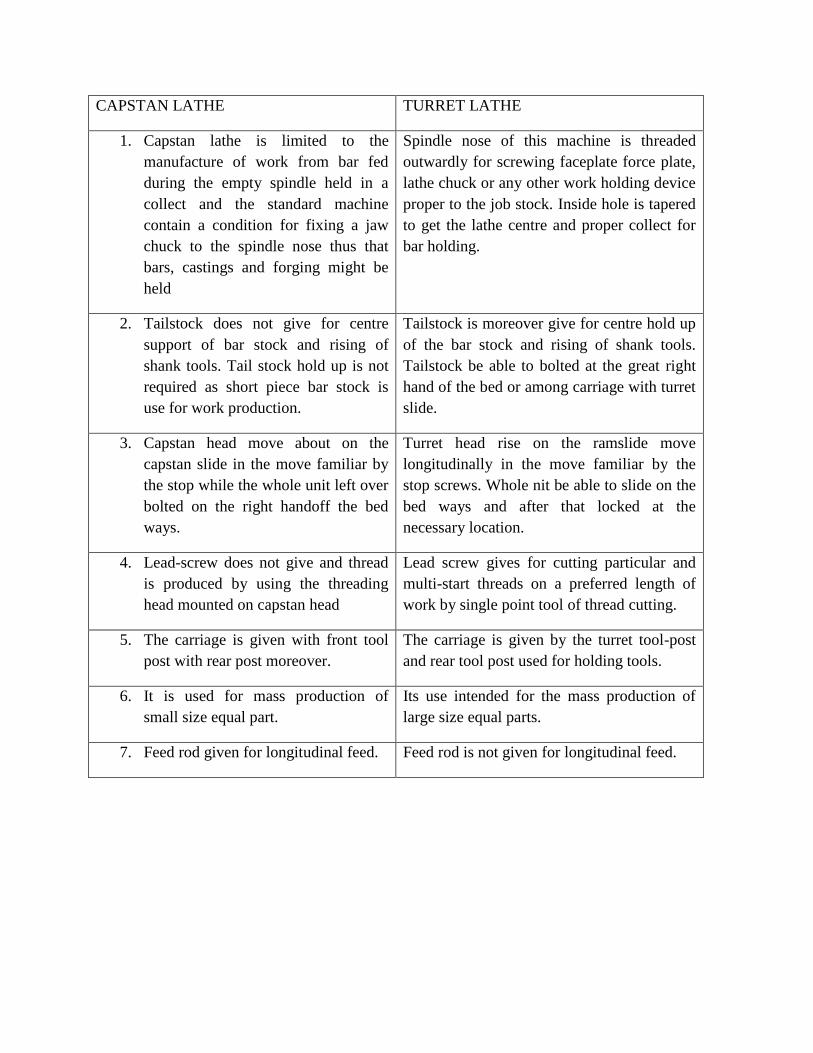
CAPSTAN LATHE TURRET LATHE
1. Capstan lathe is limited to the
manufacture of work from bar fed
during the empty spindle held in a
collect and the standard machine
contain a condition for fixing a jaw
chuck to the spindle nose thus that
bars, castings and forging might be
held
Spindle nose of this machine is threaded
outwardly for screwing faceplate force plate,
lathe chuck or any other work holding device
proper to the job stock. Inside hole is tapered
to get the lathe centre and proper collect for
bar holding.
2. Tailstock does not give for centre
support of bar stock and rising of
shank tools. Tail stock hold up is not
required as short piece bar stock is
use for work production.
Tailstock is moreover give for centre hold up
of the bar stock and rising of shank tools.
Tailstock be able to bolted at the great right
hand of the bed or among carriage with turret
slide.
3. Capstan head move about on the
capstan slide in the move familiar by
the stop while the whole unit left over
bolted on the right handoff the bed
ways.
Turret head rise on the ramslide move
longitudinally in the move familiar by the
stop screws. Whole nit be able to slide on the
bed ways and after that locked at the
necessary location.
4. Lead-screw does not give and thread
is produced by using the threading
head mounted on capstan head
Lead screw gives for cutting particular and
multi-start threads on a preferred length of
work by single point tool of thread cutting.
5. The carriage is given with front tool
post with rear post moreover.
The carriage is given by the turret tool-post
and rear tool post used for holding tools.
6. It is used for mass production of
small size equal part.
Its use intended for the mass production of
large size equal parts.
7. Feed rod given for longitudinal feed. Feed rod is not given for longitudinal feed.