Embed Size (px)
Citation preview
Non-ConventionalMachining ProcessesMANUFACTURING PROCESSES
Non-Conventional MachiningManufacturing processes can be broadly divided into two groups:
Primary manufacturing processes : Provide basic shape and size
Secondary manufacturing processes : Provide final shape and size with tighter control on dimension, surface characteristics
Non-Conventional MachiningMaterial removal processes once again can be divided into two groups
Conventional Machining Processes
Non-Traditional Manufacturing Processes or non-conventional Manufacturing processes
Non-Conventional MachiningConventional Machining Processes mostly remove material in the form of chips by applying forces on the work material with a wedge shaped cutting tool that is harder than the work material under machining condition.
The major characteristics of conventional machining are: ◦ Generally macroscopic chip formation by shear deformation
◦ Material removal takes place due to application of cutting forces – energy domain can be classified as mechanical
◦ Cutting tool is harder than work piece at room temperature as well as under machining conditions
Non-Conventional MachiningNon-conventional manufacturing processes is defined as a group of processes that remove excess material by various techniques involving mechanical, thermal, electrical or chemical energy or combinations of these energies but do not use a sharp cutting tools as it needs to be used for traditional manufacturing processes
The major characteristics of Non-conventional machining are material removal may occur with chip formation or even no chip formation may take place. For example in AJM, chips are of microscopic size and in case of Electrochemical machining material removal occurs due to electrochemical dissolution at atomic level.
Non-Conventional MachiningThe major characteristics of Non-conventional machining:
In NCM, there may not be a physical tool present. For example in laser jet machining, machining is carried out by laser beam. However in Electrochemical Machining there is a physical tool that is very much required for machining
In NCM, the tool need not be harder than the work piece material. For example, in EDM, copper is used as the tool material to machine hardened steels.
Non-Conventional MachiningMostly NCM processes do not necessarily use mechanical energy to provide material removal. They use different energy domains to provide machining. For example, in USM, AJM, WJM mechanical energy is used to machine material, whereas in ECM electrochemical dissolution constitutes material removal.
Classification of Non-Conventional MachiningThe nature of energy used for material removal.
1. Mechanical Processes
Abrasive Jet Machining (AJM)
Ultrasonic Machining (USM)
Water Jet Machining (WJM)
Abrasive Water Jet Machining (AWJM)
2. Electrochemical Processes
Electrochemical Machining (ECM)
Electro Chemical Grinding (ECG)
Electro Jet Drilling (EJD)
Continued3. Electro-Thermal Processes
Electro-discharge machining (EDM)
Laser Jet Machining (LJM)
Electron Beam Machining (EBM)
4. Chemical Processes
Chemical Milling (CHM)
Photochemical Milling (PCM)
Needs for Non-Conventional MachiningExtremely hard and brittle materials or Difficult to machine materials
When the workpiece is too flexible or slender to support the cutting or grinding forces.
When the shape of the part is too complex.
Intricate shaped blind hole – e.g. square hole of 15 mmx15 mm with a depth of 30 mm
ContinuedDeep hole with small hole diameter – e.g. φ 1.5 mm hole with l/d = 20
Machining of composites.
Abrasive Jet Machining
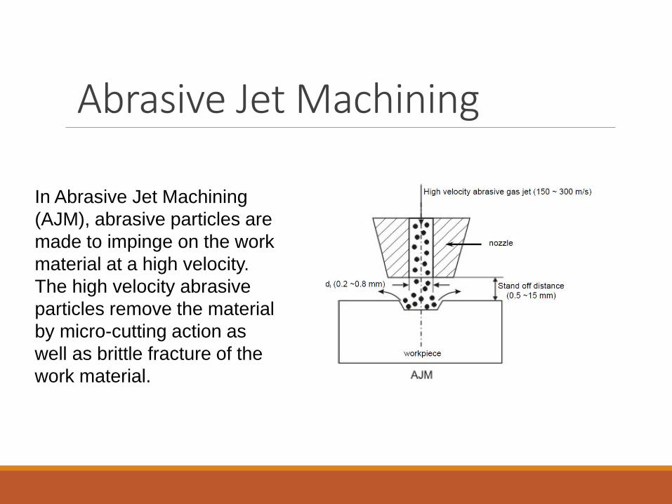
In Abrasive Jet Machining
(AJM), abrasive particles are
made to impinge on the work
material at a high velocity.
The high velocity abrasive
particles remove the material
by micro-cutting action as
well as brittle fracture of the
work material.
Abrasive Jet Machining In AJM, generally, the abrasive particles of around 50 μm grit size would impinge on the work material at velocity of 200 m/s from a nozzle of I.D. of 0.5 mm with a stand off distance of around 2 mm. The kinetic energy of the abrasive particles would be sufficient to provide material removal due to brittle fracture of the work piece or even micro cutting by the abrasives.
Abrasive Jet Machining
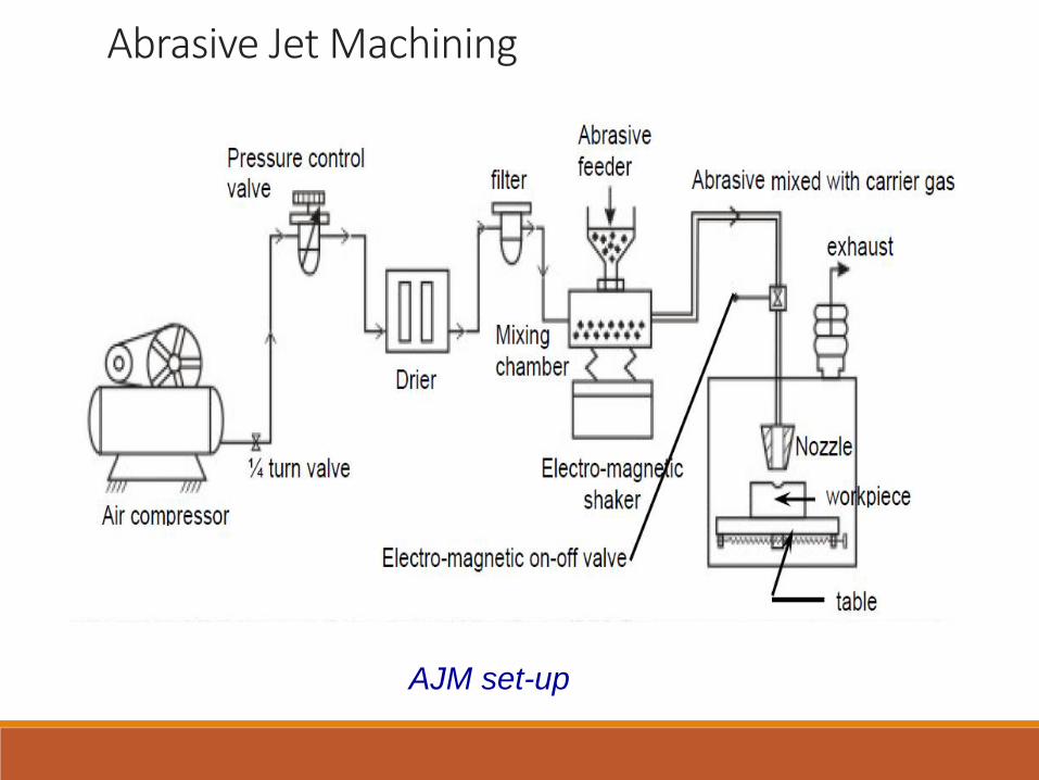
AJM set-up
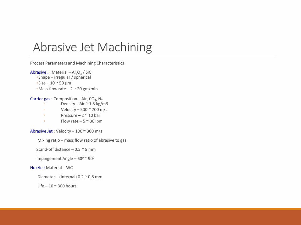
Abrasive Jet MachiningProcess Parameters and Machining Characteristics
Abrasive : Material – Al2O3 / SiC◦Shape – irregular / spherical
◦Size – 10 ~ 50 μm
◦Mass flow rate – 2 ~ 20 gm/min
Carrier gas : Composition – Air, CO2, N2
◦ Density – Air ~ 1.3 kg/m3
◦ Velocity – 500 ~ 700 m/s
◦ Pressure – 2 ~ 10 bar
◦ Flow rate – 5 ~ 30 lpm
Abrasive Jet : Velocity – 100 ~ 300 m/s
Mixing ratio – mass flow ratio of abrasive to gas
Stand-off distance – 0.5 ~ 5 mm
Impingement Angle – 600 ~ 900
Nozzle : Material – WC
Diameter – (Internal) 0.2 ~ 0.8 mm
Life – 10 ~ 300 hours
Abrasive Jet Machining
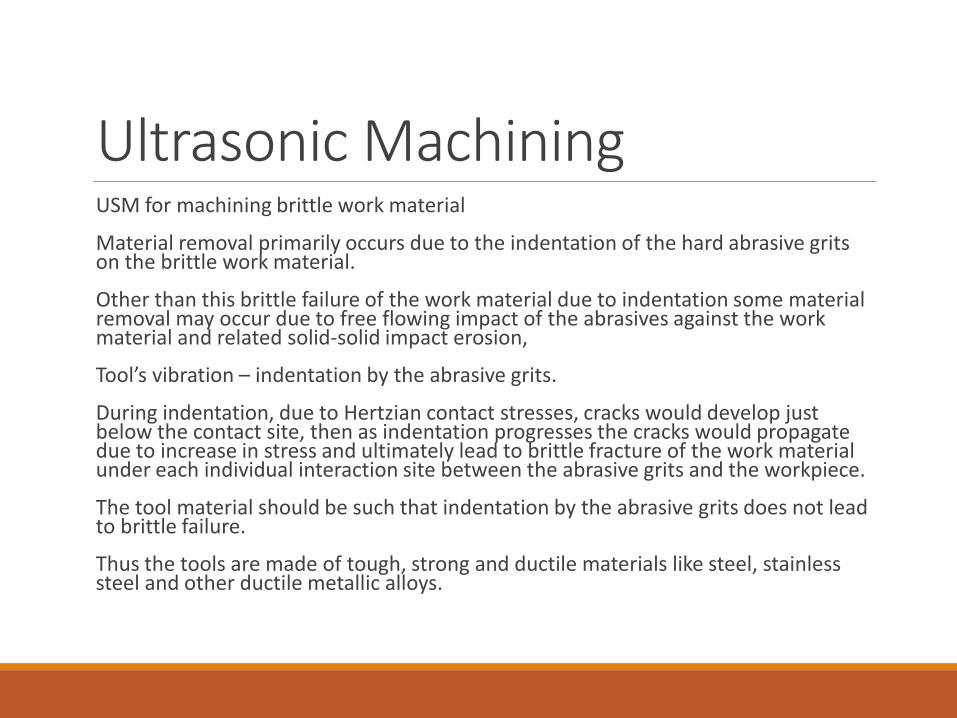
Ultrasonic MachiningUSM for machining brittle work material
Material removal primarily occurs due to the indentation of the hard abrasive grits on the brittle work material.
Other than this brittle failure of the work material due to indentation some material removal may occur due to free flowing impact of the abrasives against the work material and related solid-solid impact erosion,
Tool’s vibration – indentation by the abrasive grits.
During indentation, due to Hertzian contact stresses, cracks would develop just below the contact site, then as indentation progresses the cracks would propagate due to increase in stress and ultimately lead to brittle fracture of the work material under each individual interaction site between the abrasive grits and the workpiece.
The tool material should be such that indentation by the abrasive grits does not lead to brittle failure.
Thus the tools are made of tough, strong and ductile materials like steel, stainless steel and other ductile metallic alloys.
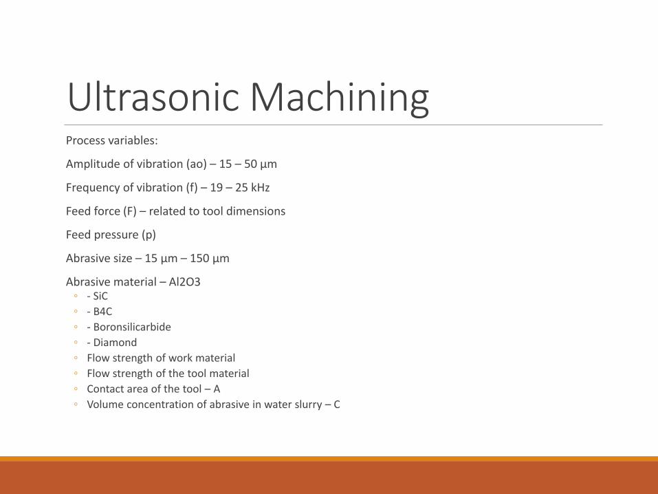
Ultrasonic MachiningProcess variables:
Amplitude of vibration (ao) – 15 – 50 μm
Frequency of vibration (f) – 19 – 25 kHz
Feed force (F) – related to tool dimensions
Feed pressure (p)
Abrasive size – 15 μm – 150 μm
Abrasive material – Al2O3 ◦ - SiC
◦ - B4C
◦ - Boronsilicarbide
◦ - Diamond
◦ Flow strength of work material
◦ Flow strength of the tool material
◦ Contact area of the tool – A
◦ Volume concentration of abrasive in water slurry – C
Ultrasonic Machining
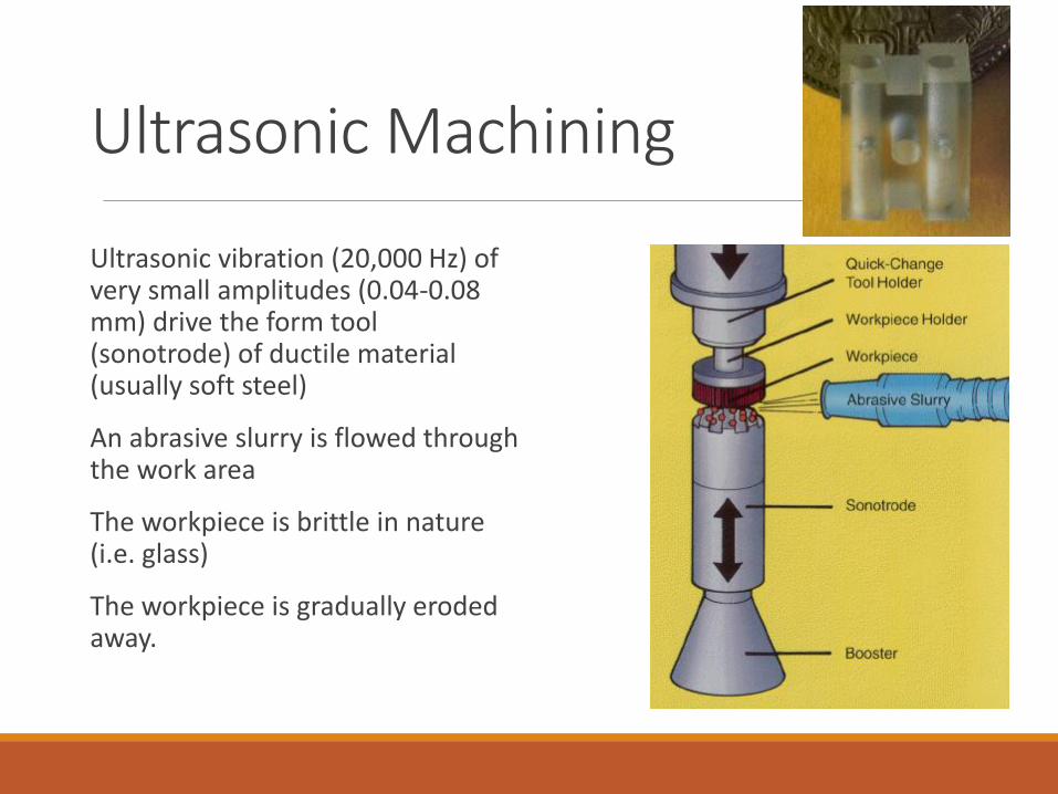
Ultrasonic vibration (20,000 Hz) of very small amplitudes (0.04-0.08 mm) drive the form tool (sonotrode) of ductile material (usually soft steel)
An abrasive slurry is flowed through the work area
The workpiece is brittle in nature (i.e. glass)
The workpiece is gradually eroded away.
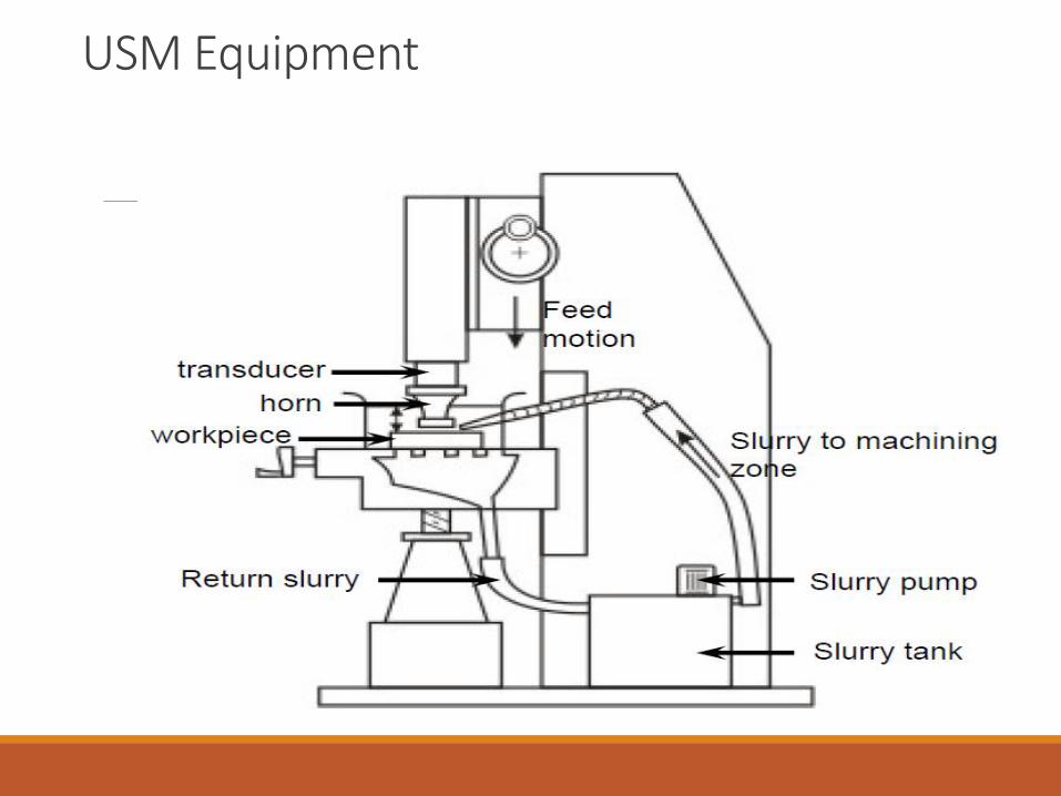
USM Equipment
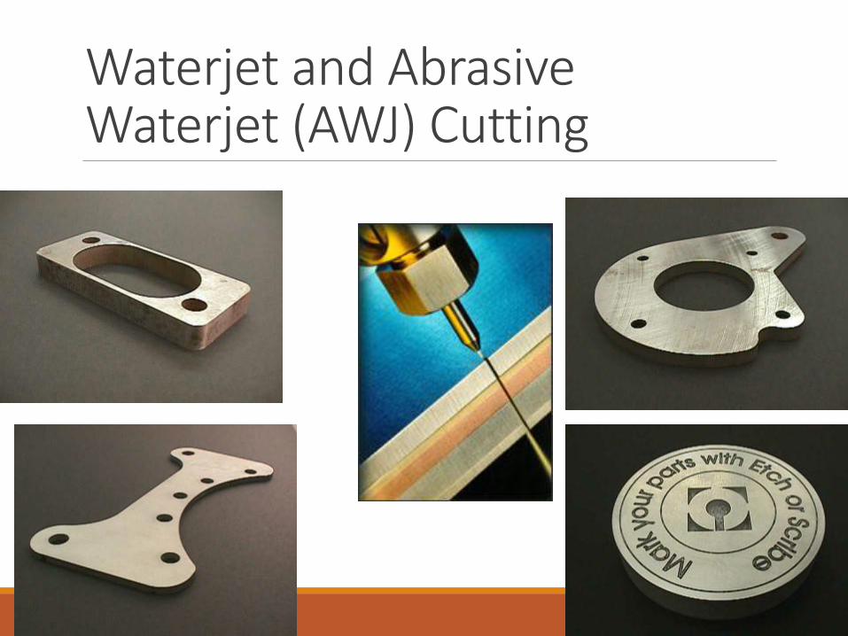
Waterjet and Abrasive Waterjet (AWJ) Cutting
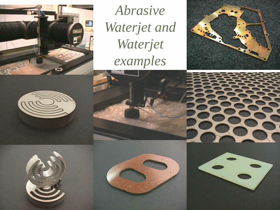
Abrasive
Waterjet and
Waterjet
examples
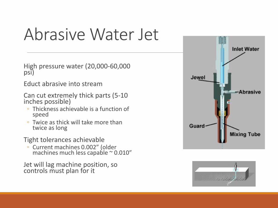
Abrasive Water Jet
High pressure water (20,000-60,000 psi)
Educt abrasive into stream
Can cut extremely thick parts (5-10 inches possible)
◦ Thickness achievable is a function of speed
◦ Twice as thick will take more than twice as long
Tight tolerances achievable ◦ Current machines 0.002” (older
machines much less capable ~ 0.010”
Jet will lag machine position, so controls must plan for it
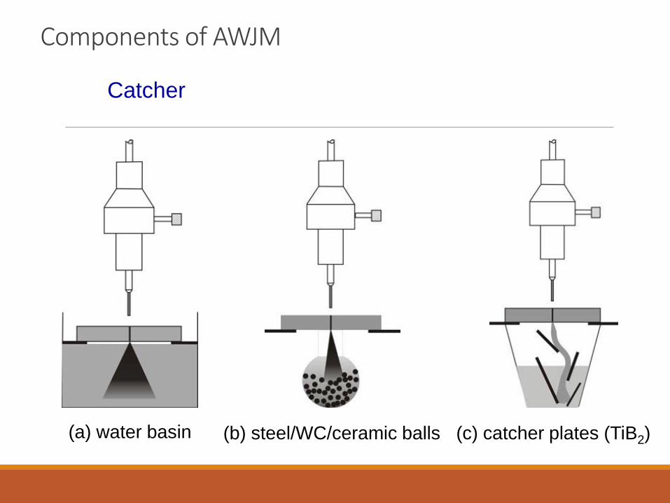
Components of AWJM
Catcher
(c) catcher plates (TiB2) (b) steel/WC/ceramic balls(a) water basin
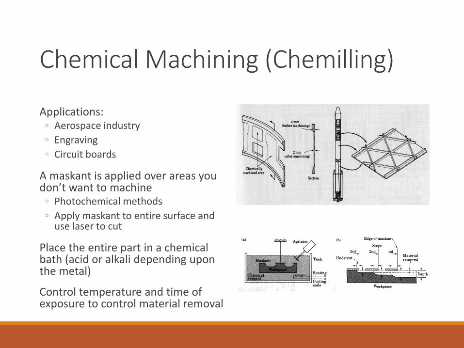
Chemical Machining (Chemilling)
Applications:◦ Aerospace industry
◦ Engraving
◦ Circuit boards
A maskant is applied over areas you don’t want to machine
◦ Photochemical methods
◦ Apply maskant to entire surface and use laser to cut
Place the entire part in a chemical bath (acid or alkali depending upon the metal)
Control temperature and time of exposure to control material removal
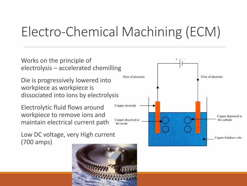
Electro-Chemical Machining (ECM)
Works on the principle of electrolysis – accelerated chemilling
Die is progressively lowered into workpiece as workpiece is dissociated into ions by electrolysis
Electrolytic fluid flows around workpiece to remove ions and maintain electrical current path
Low DC voltage, very High current (700 amps)
Electrochemical grindingCombines electrochemical machining with conventional grinding
◦ Grinding wheel is the cathode
◦ Metal bonded wheel with diamond or Al2O3 abrasive
◦ Majority of material removal from electrolytic action (95%) therefore very low wheel wear
◦ Much faster than conventional grinding
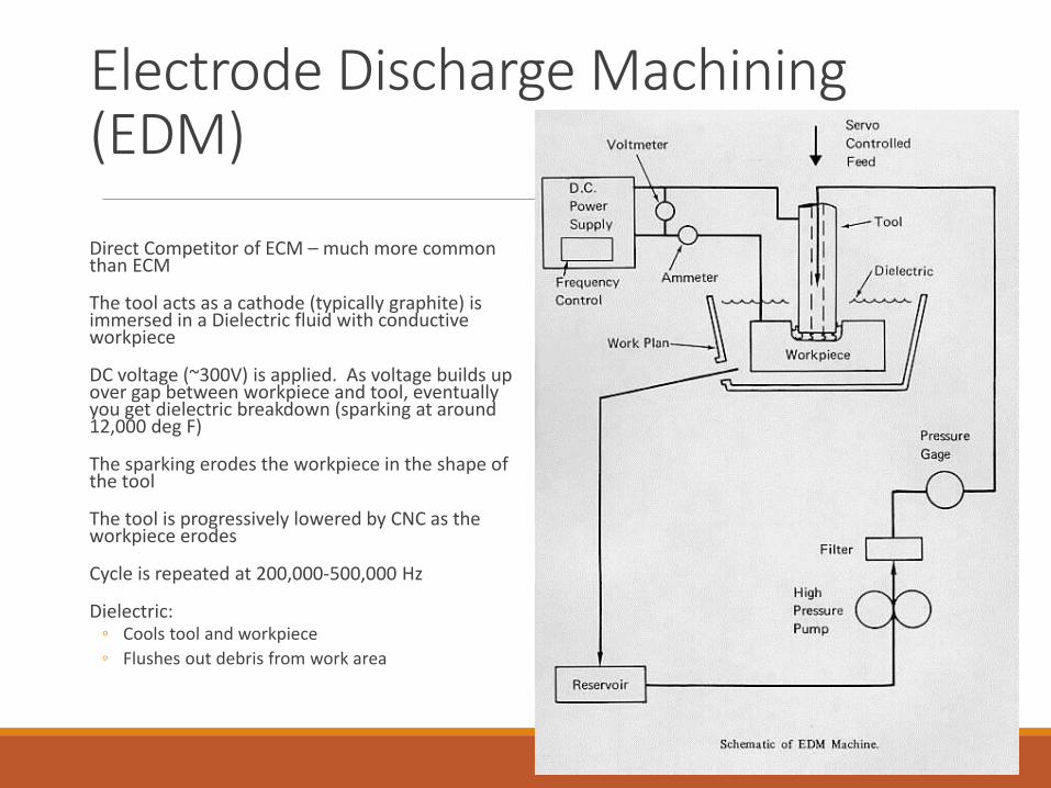
Electrode Discharge Machining (EDM)
Direct Competitor of ECM – much more common than ECM
The tool acts as a cathode (typically graphite) is immersed in a Dielectric fluid with conductive workpiece
DC voltage (~300V) is applied. As voltage builds up over gap between workpiece and tool, eventually you get dielectric breakdown (sparking at around 12,000 deg F)
The sparking erodes the workpiece in the shape of the tool
The tool is progressively lowered by CNC as the workpiece erodes
Cycle is repeated at 200,000-500,000 Hz
Dielectric:◦ Cools tool and workpiece
◦ Flushes out debris from work area
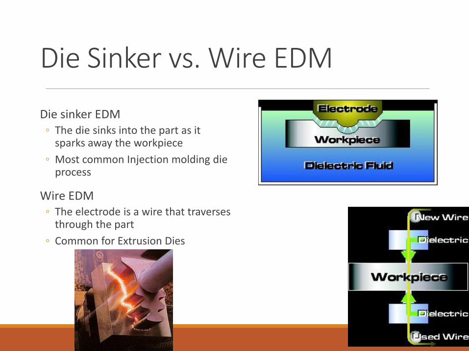
Die Sinker vs. Wire EDM
Die sinker EDM◦ The die sinks into the part as it
sparks away the workpiece
◦ Most common Injection molding die process
Wire EDM◦ The electrode is a wire that traverses
through the part
◦ Common for Extrusion Dies
Laser Beam MachiningLasers are high intensity focused light sources
◦ CO2◦ Most widely used
◦ Generally more powerful that YAG lasers
◦ Cutting operations commonly
◦ Nd:YAG (Neodymium ions in an Yttrium Aluminum Garnet)◦ Less powerful
◦ Etching/marking type operations more commonly
Limited in depth of cut (focus of light)
Would limit workpiece to less than 1 inch (< ½” typically)
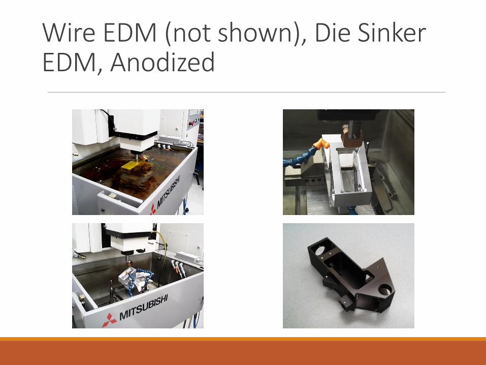
Wire EDM (not shown), Die Sinker EDM, Anodized
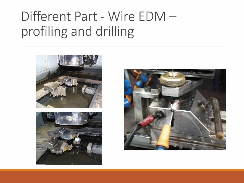
Different Part - Wire EDM –profiling and drilling
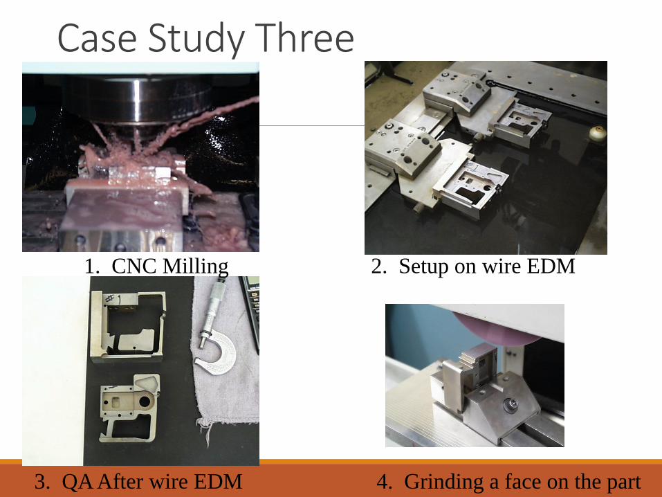
Case Study Three
1. CNC Milling 2. Setup on wire EDM
3. QA After wire EDM 4. Grinding a face on the part
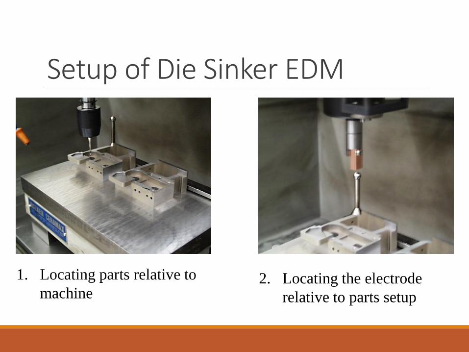
Setup of Die Sinker EDM
1. Locating parts relative to
machine2. Locating the electrode
relative to parts setup
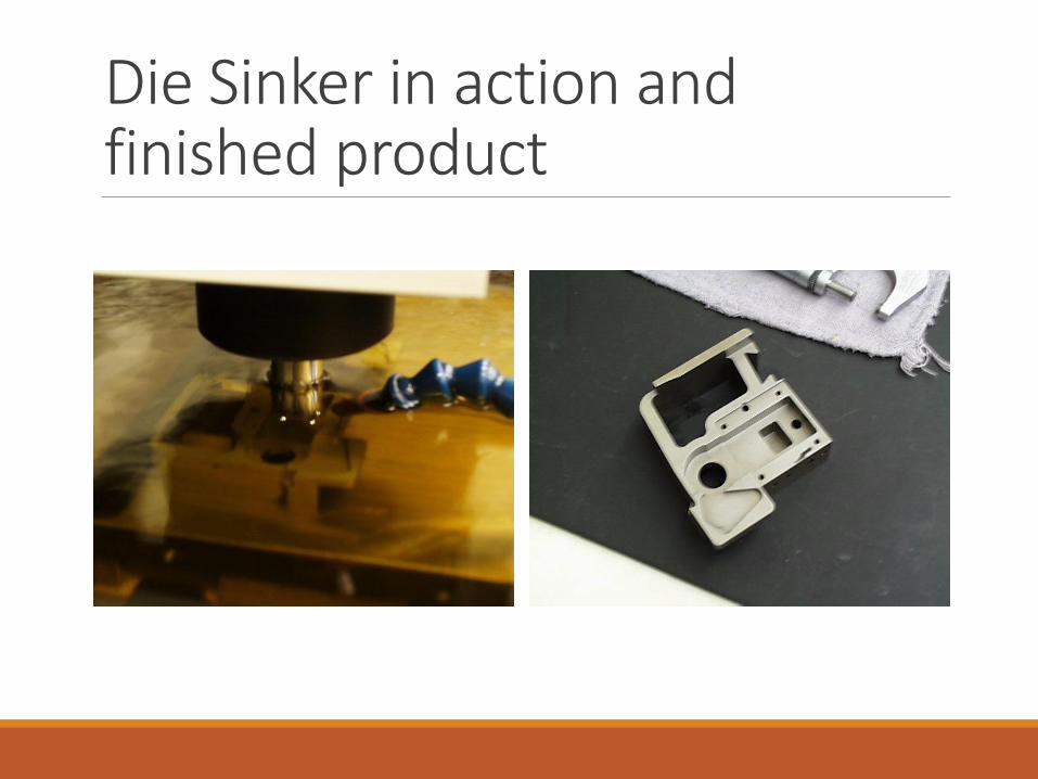
Die Sinker in action and finished product
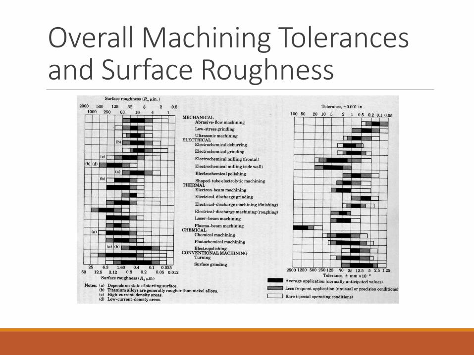
Overall Machining Tolerances and Surface Roughness