Embed Size (px)
Citation preview
Ccd
HLa
b
c
d
ARRAA
KMCNH
1
fdoddr
fdmhao
c
(A
0h
Applied Catalysis A: General 464– 465 (2013) 156– 164
Contents lists available at SciVerse ScienceDirect
Applied Catalysis A: General
j ourna l h omepa ge: www.elsev ier .com/ locate /apcata
ontrolling Co-support interaction in Co/MWCNTs catalysts andatalytic performance for hydrogen production via NH3
ecomposition
ui Zhanga, Yahia A. Alhameda,b, Wei Chuc, Zhongbin Yed, Abdulrahim AlZahrania,b,achezar Petrova,∗
SABIC Chair in Catalysis, King Abdulaziz University, P.O. Box 80204, Jeddah 21589, Saudi ArabiaChemical and Materials Engineering Department, Faculty of Engineering, King Abdulaziz University, PO Box 80204, Jeddah 21589, Saudi ArabiaSABIC Technology Center, Saudi Basic Industries Corporation, P.O. Box 42503, Riyadh 11551, Saudi ArabiaSchool of Chemistry and Chemical Engineering, Southwest Petroleum University, Chengdu 610500, China
a r t i c l e i n f o
rticle history:eceived 6 March 2013eceived in revised form 28 May 2013ccepted 30 May 2013
a b s t r a c t
The influence of thermal treatment in hydrogen and nitrogen atmosphere of Co precursors in Co/MWCNTssystem on the catalyst structure and catalytic activities in NH3 decomposition were studied. The cobalt-support interaction in cobalt supported on MWCNTs was controlled by varying the temperature ofthermal treatment of Co precursor and reaction media. Due to the interaction of cobalt species with multi
vailable online 10 June 2013
eywords:WCNTs-supported cobalt catalyst
obalt-support interactionH3 decompositionydrogen
wall carbon nanotubes (MWCNTs), the Co/MWCNTs catalysts after pretreatment in nitrogen exhibitedhigher catalytic activity for NH3 decomposition comparing to that observed after hydrogen pretreatmentof the sample. Cobalt dispersion in MWCNTs-supported catalysts was found to be a function of thermalpretreatment temperatures. The studied samples were characterized by X-ray diffraction, HRTEM, thermogravimetric analysis, temperature programmed reduction and temperature programmed desorption
© 2013 Elsevier B.V. All rights reserved.
. Introduction
Hydrogen is one of the most important clean energy carriers foruture energy systems [1–3]. At this moment, about 96% of pro-uced hydrogen in the world still comes from fossil (natural gas,il and coal) feedstocks. Alternative routes for clean hydrogen pro-uction mainly from renewable feedstocks have been intensivelyeveloped in recent years taking into account the environmentalestrictions and economic factors [4,5].
One possible option for hydrogen production from alternativeeedstocks is the decomposition of NH3. Liquid NH3 has high energyensity and high hydrogen storage capacity of 17.6 mass%, whichakes NH3 a suitable feedstock for the on-site production of clean
ydrogen [6,7]. Production of hydrogen via NH3 decomposition isttracting much attention due to many technological advantages it
ffers.Catalytic NH3 synthesis and decomposition proceed on metalatalysts. Among the different catalysts tested in the process of NH3
∗ Corresponding author. Tel.: +966 507589382; fax: +966 2 6952257.E-mail addresses: [email protected] (H. Zhang), [email protected]
Y.A. Alhamed), [email protected] (W. Chu), [email protected] (Z. Ye),[email protected] (A. AlZahrani), [email protected] (L. Petrov).
926-860X/$ – see front matter © 2013 Elsevier B.V. All rights reserved.ttp://dx.doi.org/10.1016/j.apcata.2013.05.046
decomposition, supported Ru catalysts have exhibited the high-est catalytic activity [8–12]. However, Ru is very expensive and itsreplacement by inexpensive metal catalysts is very attractive frompoint of view of future extensive practical applications.
Catalysts based on transition metals Fe, Co and Ni are the mostfeasible candidates for potential replacement of Ru catalysts forNH3 decomposition [13–17]. However, the conversion of NH3 overthose catalysts at working temperatures of PEM and alkaline fuelcells is very low. The development of highly active catalyst, whichcould increase the conversion of NH3 at low temperatures, is oneof hot topics of catalysis.
Recently, Zhang et al. [13] reported that Co catalyst supportedon commercial multi wall carbon nano tubes (MWCNTs) was moreeffective than catalyst based on Fe-containing MWCNTs. They alsohave found that the addition of Co to Fe/MWCNTs catalyst couldgreatly enhance the catalyst performance [18].
MWCNTs due to their excellent mechanical stability and elec-tronic properties find many different applications including theiruse as a catalysts support [19–22]. The major disadvantage of car-bon surfaces as a catalyst carrier is the relatively weak interaction
with the supported metal particles. This disadvantage of MWC-NTs can be overcome using different methods: (i) by attachmentof functional groups like carboxyl, carbonyl and hydroxyl to theMWCNTs surface [23–26]; (ii) by incorporation alumina on carbon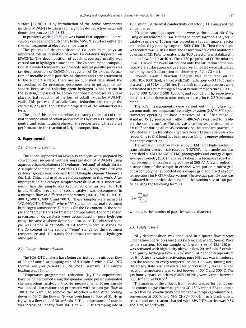
: Gene
sid
ct
iMctittpstpwcl
mnp
2
2
caAcCiuia4“ippuptta
2
otl
hcw1dNw
gas hourly space velocities (GHSV) of NH3 were varied between6000 h−1and 24,000 h−1.
The analysis of the effluent from reactor was performed by on-line connected gas chromatograph (GC-450 Varian, USA) equipped
H. Zhang et al. / Applied Catalysis A
urface [27,28]; (iii) by introduction of the active componentsnside of MWCNTs by using capillary force during active metal salteposition process [26–28,33].
In previous works [29,30], it was found that supported Co pre-ursors can be anchored strongly to the MWCNTs surface only afterhermal treatment at elevated temperatures.
The process of decomposition of Co precursors plays anmportant role in formation of active Co catalysts supported on
WCNTs. The decomposition of cobalt precursors usually wasarried out in hydrogen atmosphere. The Co precursor decomposi-ion at elevated temperatures proceeds several parallel processes.e. decomposition of Co(NO3)2, reduction of Co oxides, forma-ion of metallic cobalt particles or clusters and their attachmento the support surface. There are no published data about theroceeding of Co precursor decomposition in nitrogen atmo-phere. Because the reducing agent hydrogen is not present inhe system, in parallel to above-mentioned processes can takelace partial reduction of the formed cobalt oxides by MWCNTsalls. This process of so-called auto-reduction can change the
hemical, physical and catalytic properties of the obtained cata-ysts.
The aim of this paper, therefore, is to study the impact of ther-al decomposition of cobalt precursors in Co/MWCNTs catalysts in
eutral and reducing atmosphere on the properties and the catalysterformance in the reaction of NH3 decomposition.
. Experimental
.1. Catalyst preparation
The cobalt supported on MWCNTs catalysts were prepared byonventional incipient wetness impregnation of MWCNTs usingqueous ethanol solutions (20% volume of ethanol) of cobalt nitrate.
sample of commercial MWCNTs (O.D. = 8–15 nm) with 2.56 wt%arboxyl groups was obtained from Chengdu Organic Chemicalso., Ltd., China and used as a catalyst support in this work. After
mpregnation, the catalyst samples were dried at 70 ◦C under vac-um. Then the sample was kept at 90 ◦C in an oven for 10 h
n air. Finally, precursor of cobalt catalyst was decomposed in nitrogen flow at different temperatures (100 ◦C, 230 ◦C, 300 ◦C,00 ◦C, 500 ◦C, 600 ◦C and 700 ◦C). These samples were named asXCoMWCNTs-NTemp”, where “N” stands for thermal treatmentn nitrogen atmosphere, X’ stands for the Co content in the sam-le and “Temp” stands for treatment temperature. For comparison,recursors of Co catalysts were decomposed in pure hydrogensing the same as above-described procedure. The obtained sam-le was named as “XCoMWCNTs-HTemp”, where X’ stands forhe Co content in the sample, “Temp” stands for the treatmentemperature and “H” stands for thermal treatment in hydrogentmosphere.
.2. Catalyst characterization
The TGA–DTG analysis have being carried out in a nitrogen flowf 20 cm3 min−1 at ramping rate of 5 ◦C min−1 with a TGA–DTGhermal analyzer (STA-449 F3, NETZSCH, Germany). The sampleoading was 15 mg.
Temperature-programmed reduction (H2-TPR) experimentsave being performed using the quantachrome pulsar automatedhemisorptions analyzer. Prior to measurement, 50 mg sampleas loaded into reactor and pretreated with helium gas flow at
00 ◦C for 60 min to remove the adsorbed water. After coolingown to 50 ◦C, the flow of N2 was switching to flow of 5% H2 in2 with a flow rate of 30 cm3 min−1. The temperature of reactoras increasing linearly from 100 ◦C to 700 ◦C at a ramping rate of
ral 464– 465 (2013) 156– 164 157
10 ◦C min−1. A thermal conductivity detector (TCD) analyzed theeffluent stream.
CO chemisorption experiments were performed at 40 ◦C byusing quantachrome pulsar automatic chemisorption analyzer. Acatalyst sample of 100 mg was placed in a tubular quartz reactorand reduced by pure hydrogen at 500 ◦C for 2 h. Then the samplewas cooled to 40 ◦C in He flow. The adsorption of Co was monitoredby using a TCD. Prior to analysis, the TCD detector was stabilized inhelium flow for 1 h at 40 ◦C. Then, 250 �L pulses of CO/He mixture(15% CO in volume) were introduced until the saturation of the sur-face. Metal surface area and average crystallite size were calculatedassuming the CO adsorption stoichiometry of Co: CO = 1:1.
Powder X-ray diffraction analysis was conducted on anEQUINOX 1000 (Inel, France) with CuK� radiation (�=0.154056 nm)at a setting of 30 kV and 30 mA. The cobalt catalysts precursors werepretreated in a pure nitrogen flow at various temperatures (100 ◦C,230 ◦C, 300 ◦C,400 ◦C, 500 ◦C, 600 ◦C and 700 ◦C) for 5 h, respectivelyand then cooled down to room temperature prior to XRD measure-ment.
The XPS measurements were carried out in an ultra-highvacuum multi-technique surface analysis system (XSAM 800 spec-trometer) operating at base pressures of 10−10 bar range. Astandard X-ray source with AlK� (1486.6 eV) was used to irradi-ate the sample surface. The analysis chamber was maintained at5 x 10−9 bar during all measurements. As the standard practice inXPS studies, the adventitious hydrocarbon C 1s line (284.6 eV) cor-responding to C–C bond has been used as binding energy referencefor charge correction.
Transmission electron microscopy (TEM) and high-resolutiontransmission electron microscope (HRTEM), high angle annulardark field STEM (HAADF-STEM) photographs and energy disper-sive spectrometry (EDS) maps were taken on a Tecnai G2F20S-Twinmicroscope at an accelerating voltage of 200 kV. A few droplets ofa suspension of the sample in ethanol were put on a micro gridof carbon polymer supported on a copper grid and dried at roomtemperature for HRTEM observations. The average particle size wasevaluated from particle size based on the random size of 100 par-ticles using the following formula:
dn =∑
nidi∑ni
where ni is the number of particles with di diameter.
2.3. Catalytic tests
NH3 decomposition was conducted in a quartz flow reactorunder atmospheric pressure (PID system, Eng &Tech, Spain). Priorto the reaction, 100 mg sample with grain size of 125–180 �mwas activated with high purity nitrogen flow 20 cm3 min−1 or withhigh purity hydrogen flow 20 cm3 min−1 at defined temperaturefor 6 h. After the catalyst activation, pure NH3 gas was introducedinto the reactor. At every temperature, reaction was running untilthe steady state was achieved. This period usually takes 1 h. Thereaction temperature was varied between 400 ◦C and 500 ◦C. The
with a thermal conductivity detector and a Poropak Q column. NH3conversion at 500 ◦C and NH3 GHSV = 6000 h−1 in a blank quartzreactor and over reactor charged with MWCNTs carrier was 0.5%and 1.2%, respectively.
158 H. Zhang et al. / Applied Catalysis A: General 464– 465 (2013) 156– 164
3
3a
pspT
cri6fTF2ecco
ci
Fig. 2. CO and CO2 emissions during thermal treatment of MWCNTs support (a) and
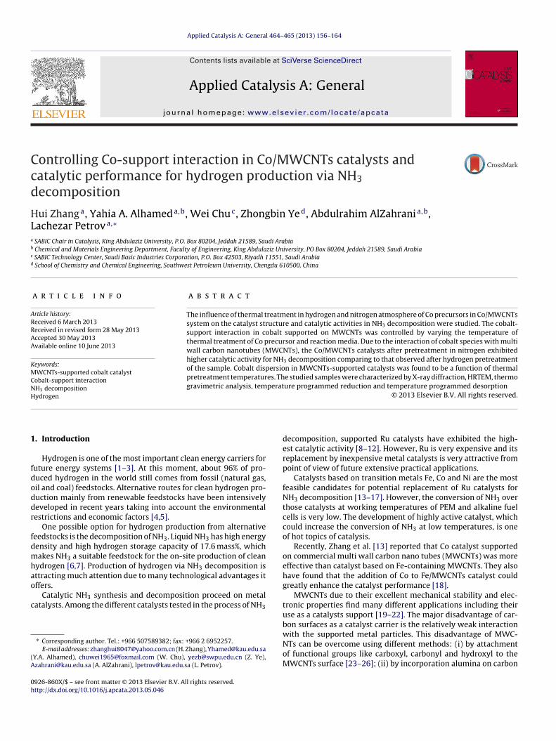
Fig. 1. TGA–DTG curves of (a) MWCNTs and (b) 10CoMWCNTs-N100.. Results and discussion
.1. Thermal decomposition of cobalt precursor in nitrogentmosphere
Decomposition of cobalt precursor is a crucial stage in catalystreparation process, which directly affects the structure of cobaltpecies in the final catalyst. The decomposition behavior of therecursors of Co/MWCNTs catalysts in nitrogen was studied byGA–DTG analysis.
The TGA–DTG curves of carbon nanotubes and of 10CoMWCNTsatalyst in nitrogen flow were depicted in Fig. 1(a) and Fig. 1(b),espectively. Over MWCNTs support, a distinct peak correspond-ng to about 10.8% weight loss was detected at temperature above52 ◦C. This peak was attributed to the decomposition of sur-ace oxygen containing groups interacted strongly with MWCNTs.GA–DTG curves of 10CoMWCNTs-N100 sample was shown inig. 1(b). Three weight loss inflections were detected at 133.9 ◦C,09.7 ◦C and 547.0 ◦C, respectively. These peaks correspond to thendothermic loss of absorbed water and water molecules in theobalt hydrate shell at 133.9 ◦C [31,32], to the decomposition of theobalt nitrate at 209.7 ◦C [29,30,33], and to the reduction of cobaltxide species at 547.0 ◦C [33–35], respectively.
The decomposition behavior of the precursors of Co/MWCNTsatalysts were also studied in quantachrome pulsar unit by record-ng CO and CO2 emissions during temperature treatment in
10CoMWCNTs-N230 catalyst (b) in nitrogen flow.
nitrogen flow. The composition of emitted gases was recorded bya mass spectrometer.
A sample from MWCNTs support dried at 120 ◦C was chargedin a quartz reactor. The temperature was increased from 100 ◦C to750 ◦C at a ramping rate of 10 ◦C min−1. There are no CO desorptionpeaks in all temperature interval as shown by Fig. 2(a). A very broaddesorption CO2 peak from MWCNTs with maximum at 230 ◦C wasobserved. It was attributed to the decomposition of carboxyl groupsexisting on the surface of MWCNTs [35].
For the study of the decomposition of Co precursors shown inFig. 2(b), the 10CoMWCNTs-N230 sample treated thermally afterpreparation at 230 ◦C in nitrogen flow have been used. The catalystsample was dried at 120 ◦C for 1 h. The temperature was increasedfrom 100 ◦C to 750 ◦C at a ramping rate of 10 ◦C min−1. Two COpeaks at 373 ◦C and 574 ◦C were registered at the reactor outlet.Probably, the weak peak at 373 ◦C could be attributed to the partialreduction of cobalt oxide species supported mainly on the surfaceinside MWCNTs. A second intensive CO peak appeared at 574 ◦C.This peak is probably a result of the reduction of Co oxides locatedon the outer surface of MWCNTs. However, no CO2 desorption peakwas observed for 10CoMWCNTs-N230 sample shown in Fig. 2(b).Probably during the procedures used for catalyst preparation, oxy-
gen containing groups has been decomposed and formed CO2 wasdesorbed.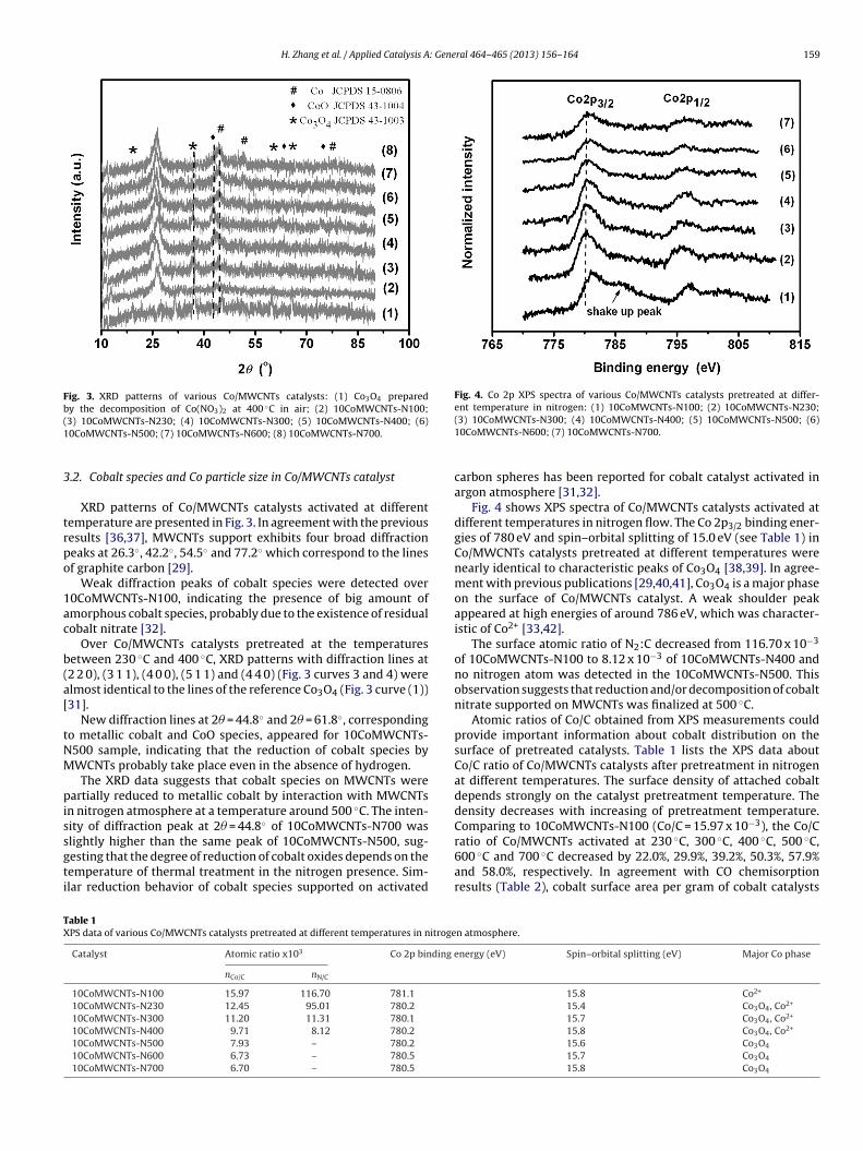
H. Zhang et al. / Applied Catalysis A: General 464– 465 (2013) 156– 164 159
Fig. 3. XRD patterns of various Co/MWCNTs catalysts: (1) Co3O4 preparedby the decomposition of Co(NO3)2 at 400 ◦C in air; (2) 10CoMWCNTs-N100;(1
3
trpo
1ac
b(a[
tNM
pissgti
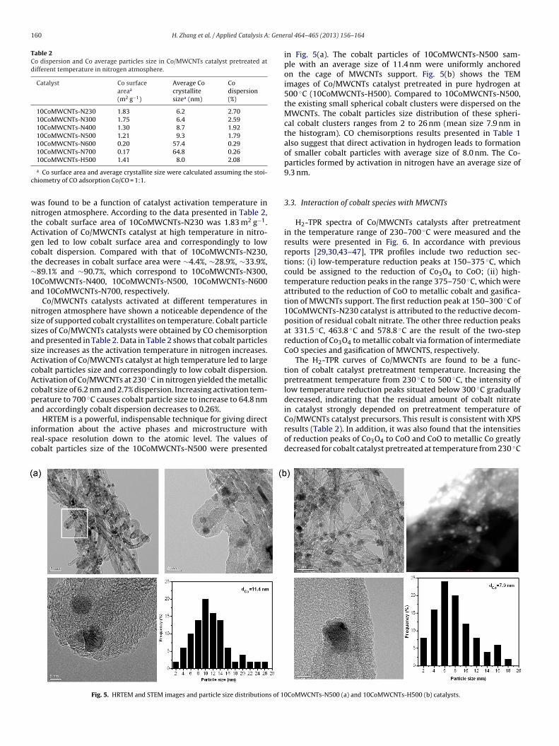
Fig. 4. Co 2p XPS spectra of various Co/MWCNTs catalysts pretreated at differ-ent temperature in nitrogen: (1) 10CoMWCNTs-N100; (2) 10CoMWCNTs-N230;
TX
3) 10CoMWCNTs-N230; (4) 10CoMWCNTs-N300; (5) 10CoMWCNTs-N400; (6)0CoMWCNTs-N500; (7) 10CoMWCNTs-N600; (8) 10CoMWCNTs-N700.
.2. Cobalt species and Co particle size in Co/MWCNTs catalyst
XRD patterns of Co/MWCNTs catalysts activated at differentemperature are presented in Fig. 3. In agreement with the previousesults [36,37], MWCNTs support exhibits four broad diffractioneaks at 26.3◦, 42.2◦, 54.5◦ and 77.2◦ which correspond to the linesf graphite carbon [29].
Weak diffraction peaks of cobalt species were detected over0CoMWCNTs-N100, indicating the presence of big amount ofmorphous cobalt species, probably due to the existence of residualobalt nitrate [32].
Over Co/MWCNTs catalysts pretreated at the temperaturesetween 230 ◦C and 400 ◦C, XRD patterns with diffraction lines at2 2 0), (3 1 1), (4 0 0), (5 1 1) and (4 4 0) (Fig. 3 curves 3 and 4) werelmost identical to the lines of the reference Co3O4 (Fig. 3 curve (1))31].
New diffraction lines at 2� = 44.8◦ and 2� = 61.8◦, correspondingo metallic cobalt and CoO species, appeared for 10CoMWCNTs-500 sample, indicating that the reduction of cobalt species byWCNTs probably take place even in the absence of hydrogen.The XRD data suggests that cobalt species on MWCNTs were
artially reduced to metallic cobalt by interaction with MWCNTsn nitrogen atmosphere at a temperature around 500 ◦C. The inten-ity of diffraction peak at 2� = 44.8◦ of 10CoMWCNTs-N700 waslightly higher than the same peak of 10CoMWCNTs-N500, sug-
esting that the degree of reduction of cobalt oxides depends on theemperature of thermal treatment in the nitrogen presence. Sim-lar reduction behavior of cobalt species supported on activatedable 1PS data of various Co/MWCNTs catalysts pretreated at different temperatures in nitroge
Catalyst Atomic ratio x103 Co 2p binding e
nCo/C nN/C
10CoMWCNTs-N100 15.97 116.70 781.1
10CoMWCNTs-N230 12.45 95.01 780.2
10CoMWCNTs-N300 11.20 11.31 780.1
10CoMWCNTs-N400 9.71 8.12 780.2
10CoMWCNTs-N500 7.93 – 780.2
10CoMWCNTs-N600 6.73 – 780.5
10CoMWCNTs-N700 6.70 – 780.5
(3) 10CoMWCNTs-N300; (4) 10CoMWCNTs-N400; (5) 10CoMWCNTs-N500; (6)10CoMWCNTs-N600; (7) 10CoMWCNTs-N700.
carbon spheres has been reported for cobalt catalyst activated inargon atmosphere [31,32].
Fig. 4 shows XPS spectra of Co/MWCNTs catalysts activated atdifferent temperatures in nitrogen flow. The Co 2p3/2 binding ener-gies of 780 eV and spin–orbital splitting of 15.0 eV (see Table 1) inCo/MWCNTs catalysts pretreated at different temperatures werenearly identical to characteristic peaks of Co3O4 [38,39]. In agree-ment with previous publications [29,40,41], Co3O4 is a major phaseon the surface of Co/MWCNTs catalyst. A weak shoulder peakappeared at high energies of around 786 eV, which was character-istic of Co2+ [33,42].
The surface atomic ratio of N2:C decreased from 116.70 x 10⁻³
of 10CoMWCNTs-N100 to 8.12 x 10⁻³ of 10CoMWCNTs-N400 andno nitrogen atom was detected in the 10CoMWCNTs-N500. Thisobservation suggests that reduction and/or decomposition of cobaltnitrate supported on MWCNTs was finalized at 500 ◦C.
Atomic ratios of Co/C obtained from XPS measurements couldprovide important information about cobalt distribution on thesurface of pretreated catalysts. Table 1 lists the XPS data aboutCo/C ratio of Co/MWCNTs catalysts after pretreatment in nitrogenat different temperatures. The surface density of attached cobaltdepends strongly on the catalyst pretreatment temperature. Thedensity decreases with increasing of pretreatment temperature.Comparing to 10CoMWCNTs-N100 (Co/C = 15.97 x 10⁻³), the Co/Cratio of Co/MWCNTs activated at 230 ◦C, 300 ◦C, 400 ◦C, 500 ◦C,
600 ◦C and 700 ◦C decreased by 22.0%, 29.9%, 39.2%, 50.3%, 57.9%and 58.0%, respectively. In agreement with CO chemisorptionresults (Table 2), cobalt surface area per gram of cobalt catalystsn atmosphere.
nergy (eV) Spin–orbital splitting (eV) Major Co phase
15.8 Co2+
15.4 Co3O4, Co2+
15.7 Co3O4, Co2+
15.8 Co3O4, Co2+
15.6 Co3O4
15.7 Co3O4
15.8 Co3O4
160 H. Zhang et al. / Applied Catalysis A: Gene
Table 2Co dispersion and Co average particles size in Co/MWCNTs catalyst pretreated atdifferent temperature in nitrogen atmosphere.
Catalyst Co surfaceareaa
(m2 g−1)
Average Cocrystallitesizea (nm)
Codispersion(%)
10CoMWCNTs-N230 1.83 6.2 2.7010CoMWCNTs-N300 1.75 6.4 2.5910CoMWCNTs-N400 1.30 8.7 1.9210CoMWCNTs-N500 1.21 9.3 1.7910CoMWCNTs-N600 0.20 57.4 0.2910CoMWCNTs-N700 0.17 64.8 0.2610CoMWCNTs-H500 1.41 8.0 2.08
c
wntAgct∼1a
nssasAcAcpa
irc
a Co surface area and average crystallite size were calculated assuming the stoi-hiometry of CO adsorption Co/CO = 1:1.
as found to be a function of catalyst activation temperature initrogen atmosphere. According to the data presented in Table 2,he cobalt surface area of 10CoMWCNTs-N230 was 1.83 m2 g−1.ctivation of Co/MWCNTs catalyst at high temperature in nitro-en led to low cobalt surface area and correspondingly to lowobalt dispersion. Compared with that of 10CoMWCNTs-N230,he decreases in cobalt surface area were ∼4.4%, ∼28.9%, ∼33.9%,89.1% and ∼90.7%, which correspond to 10CoMWCNTs-N300,0CoMWCNTs-N400, 10CoMWCNTs-N500, 10CoMWCNTs-N600nd 10CoMWCNTs-N700, respectively.
Co/MWCNTs catalysts activated at different temperatures initrogen atmosphere have shown a noticeable dependence of theize of supported cobalt crystallites on temperature. Cobalt particleizes of Co/MWCNTs catalysts were obtained by CO chemisorptionnd presented in Table 2. Data in Table 2 shows that cobalt particlesize increases as the activation temperature in nitrogen increases.ctivation of Co/MWCNTs catalyst at high temperature led to largeobalt particles size and correspondingly to low cobalt dispersion.ctivation of Co/MWCNTs at 230 ◦C in nitrogen yielded the metallicobalt size of 6.2 nm and 2.7% dispersion. Increasing activation tem-erature to 700 ◦C causes cobalt particle size to increase to 64.8 nmnd accordingly cobalt dispersion decreases to 0.26%.
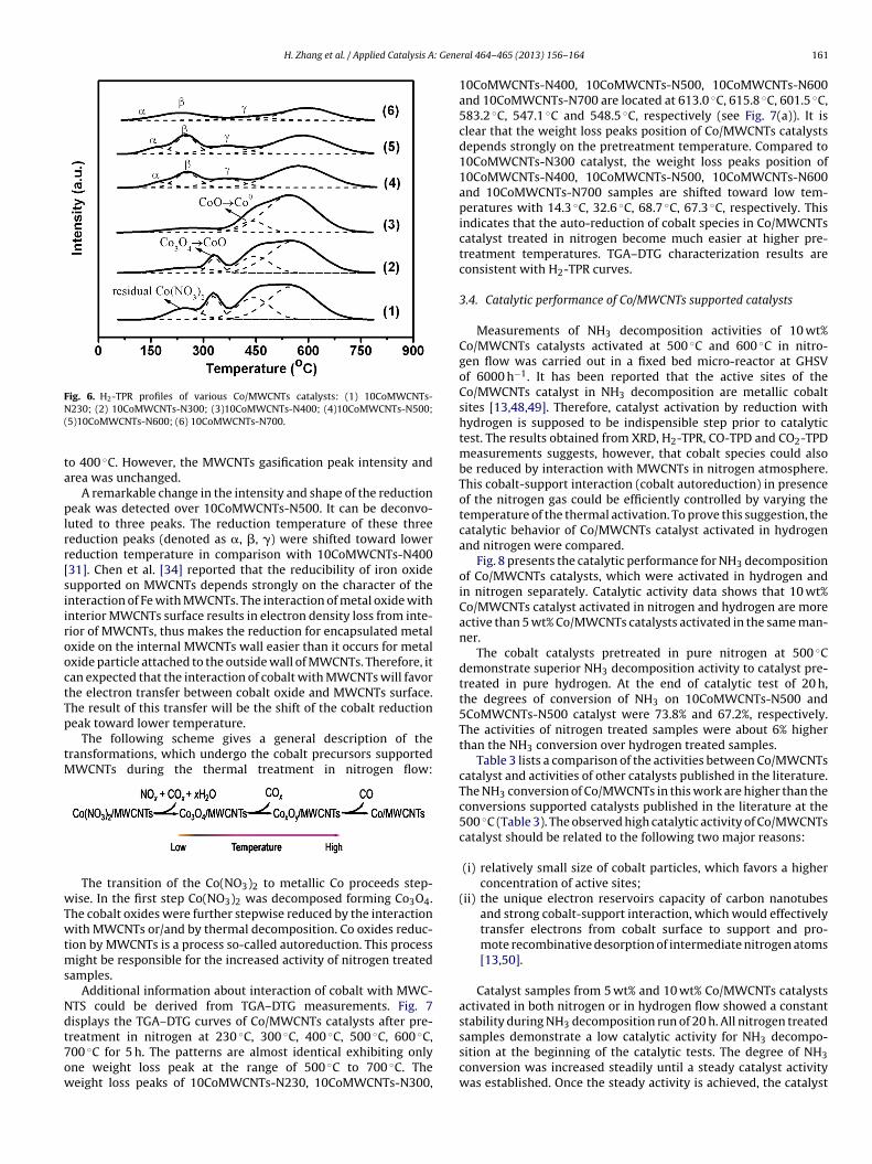
HRTEM is a powerful, indispensable technique for giving directnformation about the active phases and microstructure witheal-space resolution down to the atomic level. The values ofobalt particles size of the 10CoMWCNTs-N500 were presented
Fig. 5. HRTEM and STEM images and particle size distributions of 1
ral 464– 465 (2013) 156– 164
in Fig. 5(a). The cobalt particles of 10CoMWCNTs-N500 sam-ple with an average size of 11.4 nm were uniformly anchoredon the cage of MWCNTs support. Fig. 5(b) shows the TEMimages of Co/MWCNTs catalyst pretreated in pure hydrogen at500 ◦C (10CoMWCNTs-H500). Compared to 10CoMWCNTs-N500,the existing small spherical cobalt clusters were dispersed on theMWCNTs. The cobalt particles size distribution of these spheri-cal cobalt clusters ranges from 2 to 26 nm (mean size 7.9 nm inthe histogram). CO chemisorptions results presented in Table 1also suggest that direct activation in hydrogen leads to formationof smaller cobalt particles with average size of 8.0 nm. The Co-particles formed by activation in nitrogen have an average size of9.3 nm.
3.3. Interaction of cobalt species with MWCNTs
H2-TPR spectra of Co/MWCNTs catalysts after pretreatmentin the temperature range of 230–700 ◦C were measured and theresults were presented in Fig. 6. In accordance with previousreports [29,30,43–47], TPR profiles include two reduction sec-tions: (i) low-temperature reduction peaks at 150–375 ◦C, whichcould be assigned to the reduction of Co3O4 to CoO; (ii) high-temperature reduction peaks in the range 375–750 ◦C, which wereattributed to the reduction of CoO to metallic cobalt and gasifica-tion of MWCNTs support. The first reduction peak at 150–300 ◦C of10CoMWCNTs-N230 catalyst is attributed to the reductive decom-position of residual cobalt nitrate. The other three reduction peaksat 331.5 ◦C, 463.8 ◦C and 578.8 ◦C are the result of the two-stepreduction of Co3O4 to metallic cobalt via formation of intermediateCoO species and gasification of MWCNTS, respectively.
The H2-TPR curves of Co/MWCNTs are found to be a func-tion of cobalt catalyst pretreatment temperature. Increasing thepretreatment temperature from 230 ◦C to 500 ◦C, the intensity oflow temperature reduction peaks situated below 300 ◦C graduallydecreased, indicating that the residual amount of cobalt nitratein catalyst strongly depended on pretreatment temperature of
Co/MWCNTs catalyst precursors. This result is consistent with XPSresults (Table 2). In addition, it was also found that the intensitiesof reduction peaks of Co3O4 to CoO and CoO to metallic Co greatlydecreased for cobalt catalyst pretreated at temperature from 230 ◦C0CoMWCNTs-N500 (a) and 10CoMWCNTs-H500 (b) catalysts.
H. Zhang et al. / Applied Catalysis A: Gene
Fig. 6. H2-TPR profiles of various Co/MWCNTs catalysts: (1) 10CoMWCNTs-N(
ta
plrr[siirooctTp
tM
wTwtms
Ndt7ow
230; (2) 10CoMWCNTs-N300; (3)10CoMWCNTs-N400; (4)10CoMWCNTs-N500;5)10CoMWCNTs-N600; (6) 10CoMWCNTs-N700.
o 400 ◦C. However, the MWCNTs gasification peak intensity andrea was unchanged.
A remarkable change in the intensity and shape of the reductioneak was detected over 10CoMWCNTs-N500. It can be deconvo-
uted to three peaks. The reduction temperature of these threeeduction peaks (denoted as �, �, �) were shifted toward lowereduction temperature in comparison with 10CoMWCNTs-N40031]. Chen et al. [34] reported that the reducibility of iron oxideupported on MWCNTs depends strongly on the character of thenteraction of Fe with MWCNTs. The interaction of metal oxide withnterior MWCNTs surface results in electron density loss from inte-ior of MWCNTs, thus makes the reduction for encapsulated metalxide on the internal MWCNTs wall easier than it occurs for metalxide particle attached to the outside wall of MWCNTs. Therefore, itan expected that the interaction of cobalt with MWCNTs will favorhe electron transfer between cobalt oxide and MWCNTs surface.he result of this transfer will be the shift of the cobalt reductioneak toward lower temperature.
The following scheme gives a general description of theransformations, which undergo the cobalt precursors supported
WCNTs during the thermal treatment in nitrogen flow:
The transition of the Co(NO3)2 to metallic Co proceeds step-ise. In the first step Co(NO3)2 was decomposed forming Co3O4.
he cobalt oxides were further stepwise reduced by the interactionith MWCNTs or/and by thermal decomposition. Co oxides reduc-
ion by MWCNTs is a process so-called autoreduction. This processight be responsible for the increased activity of nitrogen treated
amples.Additional information about interaction of cobalt with MWC-
TS could be derived from TGA–DTG measurements. Fig. 7isplays the TGA–DTG curves of Co/MWCNTs catalysts after pre-
◦ ◦ ◦ ◦ ◦
reatment in nitrogen at 230 C, 300 C, 400 C, 500 C, 600 C,00 ◦C for 5 h. The patterns are almost identical exhibiting onlyne weight loss peak at the range of 500 ◦C to 700 ◦C. Theeight loss peaks of 10CoMWCNTs-N230, 10CoMWCNTs-N300,ral 464– 465 (2013) 156– 164 161
10CoMWCNTs-N400, 10CoMWCNTs-N500, 10CoMWCNTs-N600and 10CoMWCNTs-N700 are located at 613.0 ◦C, 615.8 ◦C, 601.5 ◦C,583.2 ◦C, 547.1 ◦C and 548.5 ◦C, respectively (see Fig. 7(a)). It isclear that the weight loss peaks position of Co/MWCNTs catalystsdepends strongly on the pretreatment temperature. Compared to10CoMWCNTs-N300 catalyst, the weight loss peaks position of10CoMWCNTs-N400, 10CoMWCNTs-N500, 10CoMWCNTs-N600and 10CoMWCNTs-N700 samples are shifted toward low tem-peratures with 14.3 ◦C, 32.6 ◦C, 68.7 ◦C, 67.3 ◦C, respectively. Thisindicates that the auto-reduction of cobalt species in Co/MWCNTscatalyst treated in nitrogen become much easier at higher pre-treatment temperatures. TGA–DTG characterization results areconsistent with H2-TPR curves.
3.4. Catalytic performance of Co/MWCNTs supported catalysts
Measurements of NH3 decomposition activities of 10 wt%Co/MWCNTs catalysts activated at 500 ◦C and 600 ◦C in nitro-gen flow was carried out in a fixed bed micro-reactor at GHSVof 6000 h−1. It has been reported that the active sites of theCo/MWCNTs catalyst in NH3 decomposition are metallic cobaltsites [13,48,49]. Therefore, catalyst activation by reduction withhydrogen is supposed to be indispensible step prior to catalytictest. The results obtained from XRD, H2-TPR, CO-TPD and CO2-TPDmeasurements suggests, however, that cobalt species could alsobe reduced by interaction with MWCNTs in nitrogen atmosphere.This cobalt-support interaction (cobalt autoreduction) in presenceof the nitrogen gas could be efficiently controlled by varying thetemperature of the thermal activation. To prove this suggestion, thecatalytic behavior of Co/MWCNTs catalyst activated in hydrogenand nitrogen were compared.
Fig. 8 presents the catalytic performance for NH3 decompositionof Co/MWCNTs catalysts, which were activated in hydrogen andin nitrogen separately. Catalytic activity data shows that 10 wt%Co/MWCNTs catalyst activated in nitrogen and hydrogen are moreactive than 5 wt% Co/MWCNTs catalysts activated in the same man-ner.
The cobalt catalysts pretreated in pure nitrogen at 500 ◦Cdemonstrate superior NH3 decomposition activity to catalyst pre-treated in pure hydrogen. At the end of catalytic test of 20 h,the degrees of conversion of NH3 on 10CoMWCNTs-N500 and5CoMWCNTs-N500 catalyst were 73.8% and 67.2%, respectively.The activities of nitrogen treated samples were about 6% higherthan the NH3 conversion over hydrogen treated samples.
Table 3 lists a comparison of the activities between Co/MWCNTscatalyst and activities of other catalysts published in the literature.The NH3 conversion of Co/MWCNTs in this work are higher than theconversions supported catalysts published in the literature at the500 ◦C (Table 3). The observed high catalytic activity of Co/MWCNTscatalyst should be related to the following two major reasons:
(i) relatively small size of cobalt particles, which favors a higherconcentration of active sites;
(ii) the unique electron reservoirs capacity of carbon nanotubesand strong cobalt-support interaction, which would effectivelytransfer electrons from cobalt surface to support and pro-mote recombinative desorption of intermediate nitrogen atoms[13,50].
Catalyst samples from 5 wt% and 10 wt% Co/MWCNTs catalystsactivated in both nitrogen or in hydrogen flow showed a constantstability during NH3 decomposition run of 20 h. All nitrogen treated
samples demonstrate a low catalytic activity for NH3 decompo-sition at the beginning of the catalytic tests. The degree of NH3conversion was increased steadily until a steady catalyst activitywas established. Once the steady activity is achieved, the catalyst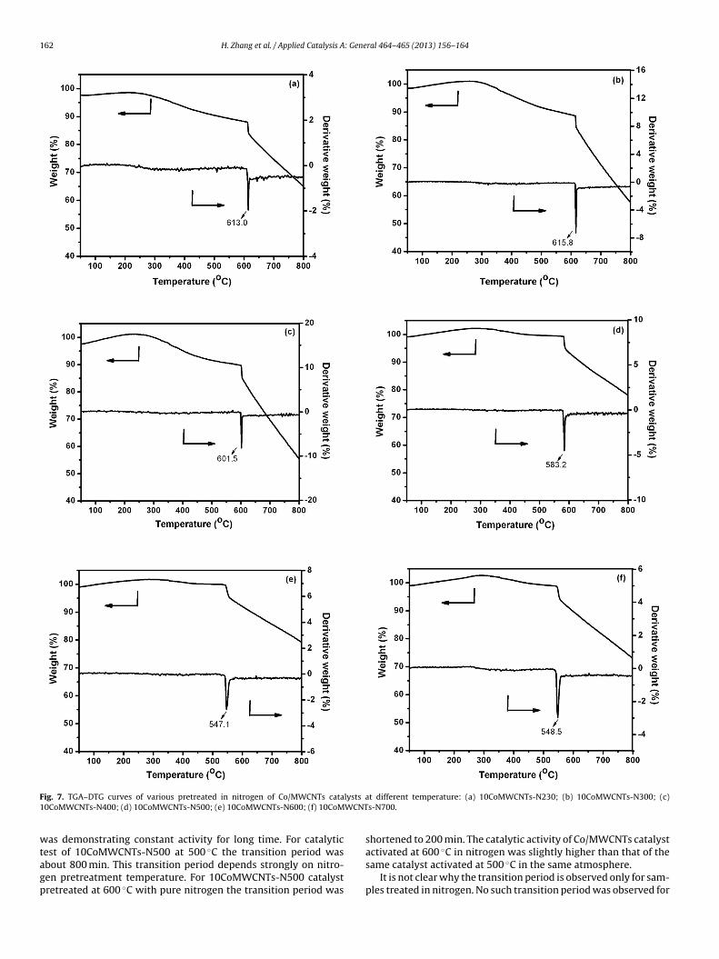
162 H. Zhang et al. / Applied Catalysis A: General 464– 465 (2013) 156– 164
F lysts a1 WCNT
wtagp
ig. 7. TGA–DTG curves of various pretreated in nitrogen of Co/MWCNTs cata0CoMWCNTs-N400; (d) 10CoMWCNTs-N500; (e) 10CoMWCNTs-N600; (f) 10CoM
as demonstrating constant activity for long time. For catalytic
est of 10CoMWCNTs-N500 at 500 ◦C the transition period wasbout 800 min. This transition period depends strongly on nitro-en pretreatment temperature. For 10CoMWCNTs-N500 catalystretreated at 600 ◦C with pure nitrogen the transition period wast different temperature: (a) 10CoMWCNTs-N230; (b) 10CoMWCNTs-N300; (c)s-N700.
shortened to 200 min. The catalytic activity of Co/MWCNTs catalyst
activated at 600 ◦C in nitrogen was slightly higher than that of thesame catalyst activated at 500 ◦C in the same atmosphere.It is not clear why the transition period is observed only for sam-ples treated in nitrogen. No such transition period was observed for
H. Zhang et al. / Applied Catalysis A: General 464– 465 (2013) 156– 164 163
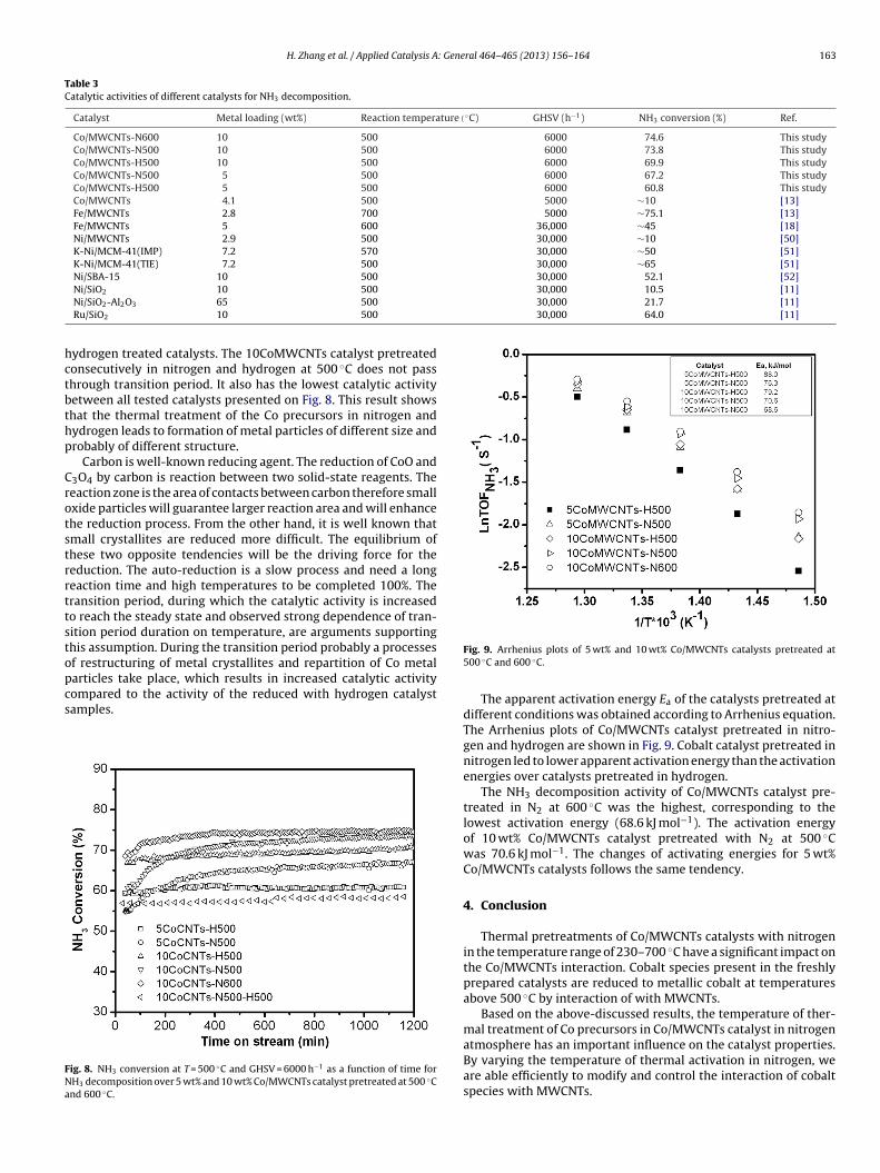
Table 3Catalytic activities of different catalysts for NH3 decomposition.
Catalyst Metal loading (wt%) Reaction temperature(◦C) GHSV (h−1) NH3 conversion (%) Ref.
Co/MWCNTs-N600 10 500 6000 74.6 This studyCo/MWCNTs-N500 10 500 6000 73.8 This studyCo/MWCNTs-H500 10 500 6000 69.9 This studyCo/MWCNTs-N500 5 500 6000 67.2 This studyCo/MWCNTs-H500 5 500 6000 60.8 This studyCo/MWCNTs 4.1 500 5000 ∼10 [13]Fe/MWCNTs 2.8 700 5000 ∼75.1 [13]Fe/MWCNTs 5 600 36,000 ∼45 [18]Ni/MWCNTs 2.9 500 30,000 ∼10 [50]K-Ni/MCM-41(IMP) 7.2 570 30,000 ∼50 [51]K-Ni/MCM-41(TIE) 7.2 500 30,000 ∼65 [51]Ni/SBA-15 10 500 30,000 52.1 [52]
30,000 10.5 [11]30,000 21.7 [11]30,000 64.0 [11]
hctbthp
Crotstrrttstopcs
FNa
Ni/SiO2 10 500
Ni/SiO2-Al2O3 65 500
Ru/SiO2 10 500
ydrogen treated catalysts. The 10CoMWCNTs catalyst pretreatedonsecutively in nitrogen and hydrogen at 500 ◦C does not passhrough transition period. It also has the lowest catalytic activityetween all tested catalysts presented on Fig. 8. This result showshat the thermal treatment of the Co precursors in nitrogen andydrogen leads to formation of metal particles of different size androbably of different structure.
Carbon is well-known reducing agent. The reduction of CoO and3O4 by carbon is reaction between two solid-state reagents. Theeaction zone is the area of contacts between carbon therefore smallxide particles will guarantee larger reaction area and will enhancehe reduction process. From the other hand, it is well known thatmall crystallites are reduced more difficult. The equilibrium ofhese two opposite tendencies will be the driving force for theeduction. The auto-reduction is a slow process and need a longeaction time and high temperatures to be completed 100%. Theransition period, during which the catalytic activity is increasedo reach the steady state and observed strong dependence of tran-ition period duration on temperature, are arguments supportinghis assumption. During the transition period probably a processesf restructuring of metal crystallites and repartition of Co metal
articles take place, which results in increased catalytic activityompared to the activity of the reduced with hydrogen catalystamples.ig. 8. NH3 conversion at T = 500 ◦C and GHSV = 6000 h−1 as a function of time forH3 decomposition over 5 wt% and 10 wt% Co/MWCNTs catalyst pretreated at 500 ◦Cnd 600 ◦C.
Fig. 9. Arrhenius plots of 5 wt% and 10 wt% Co/MWCNTs catalysts pretreated at500 ◦C and 600 ◦C.
The apparent activation energy Ea of the catalysts pretreated atdifferent conditions was obtained according to Arrhenius equation.The Arrhenius plots of Co/MWCNTs catalyst pretreated in nitro-gen and hydrogen are shown in Fig. 9. Cobalt catalyst pretreated innitrogen led to lower apparent activation energy than the activationenergies over catalysts pretreated in hydrogen.
The NH3 decomposition activity of Co/MWCNTs catalyst pre-treated in N2 at 600 ◦C was the highest, corresponding to thelowest activation energy (68.6 kJ mol−1). The activation energyof 10 wt% Co/MWCNTs catalyst pretreated with N2 at 500 ◦Cwas 70.6 kJ mol−1. The changes of activating energies for 5 wt%Co/MWCNTs catalysts follows the same tendency.
4. Conclusion
Thermal pretreatments of Co/MWCNTs catalysts with nitrogenin the temperature range of 230–700 ◦C have a significant impact onthe Co/MWCNTs interaction. Cobalt species present in the freshlyprepared catalysts are reduced to metallic cobalt at temperaturesabove 500 ◦C by interaction of with MWCNTs.
Based on the above-discussed results, the temperature of ther-mal treatment of Co precursors in Co/MWCNTs catalyst in nitrogen
atmosphere has an important influence on the catalyst properties.By varying the temperature of thermal activation in nitrogen, weare able efficiently to modify and control the interaction of cobaltspecies with MWCNTs.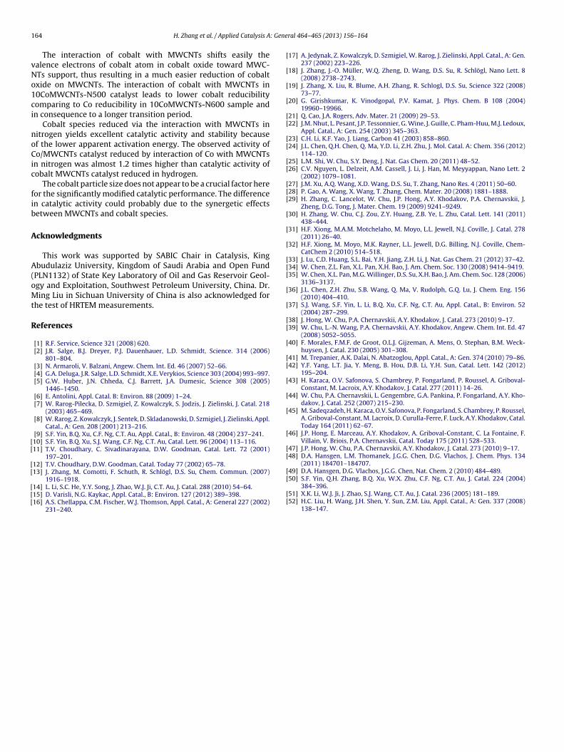
1 : Gene
vNo1ci
noCic
fib
A
A(oMt
R
[[
[[
[[[
[
[
[
[
[[
[[
[[
[[[
[
[
[
[[[
[
[
[[
[
[[
[
[
[
[
[[
[
64 H. Zhang et al. / Applied Catalysis A
The interaction of cobalt with MWCNTs shifts easily thealence electrons of cobalt atom in cobalt oxide toward MWC-Ts support, thus resulting in a much easier reduction of cobaltxide on MWCNTs. The interaction of cobalt with MWCNTs in0CoMWCNTs-N500 catalyst leads to lower cobalt reducibilityomparing to Co reducibility in 10CoMWCNTs-N600 sample andn consequence to a longer transition period.
Cobalt species reduced via the interaction with MWCNTs initrogen yields excellent catalytic activity and stability becausef the lower apparent activation energy. The observed activity ofo/MWCNTs catalyst reduced by interaction of Co with MWCNTs
n nitrogen was almost 1.2 times higher than catalytic activity ofobalt MWCNTs catalyst reduced in hydrogen.
The cobalt particle size does not appear to be a crucial factor hereor the significantly modified catalytic performance. The differencen catalytic activity could probably due to the synergetic effectsetween MWCNTs and cobalt species.
cknowledgments
This work was supported by SABIC Chair in Catalysis, Kingbudulaziz University, Kingdom of Saudi Arabia and Open Fund
PLN1132) of State Key Laboratory of Oil and Gas Reservoir Geol-gy and Exploitation, Southwest Petroleum University, China. Dr.ing Liu in Sichuan University of China is also acknowledged for
he test of HRTEM measurements.
eferences
[1] R.F. Service, Science 321 (2008) 620.[2] J.R. Salge, B.J. Dreyer, P.J. Dauenhauer, L.D. Schmidt, Science. 314 (2006)
801–804.[3] N. Armaroli, V. Balzani, Angew. Chem. Int. Ed. 46 (2007) 52–66.[4] G.A. Deluga, J.R. Salge, L.D. Schmidt, X.E. Verykios, Science 303 (2004) 993–997.[5] G.W. Huber, J.N. Chheda, C.J. Barrett, J.A. Dumesic, Science 308 (2005)
1446–1450.[6] E. Antolini, Appl. Catal. B: Environ. 88 (2009) 1–24.[7] W. Rarog-Pilecka, D. Szmigiel, Z. Kowalczyk, S. Jodzis, J. Zielinski, J. Catal. 218
(2003) 465–469.[8] W. Rarog, Z. Kowalczyk, J. Sentek, D. Skladanowski, D. Szmigiel, J. Zielinski, Appl.
Catal., A: Gen. 208 (2001) 213–216.[9] S.F. Yin, B.Q. Xu, C.F. Ng, C.T. Au, Appl. Catal., B: Environ. 48 (2004) 237–241.10] S.F. Yin, B.Q. Xu, S.J. Wang, C.F. Ng, C.T. Au, Catal. Lett. 96 (2004) 113–116.11] T.V. Choudhary, C. Sivadinarayana, D.W. Goodman, Catal. Lett. 72 (2001)
197–201.12] T.V. Choudhary, D.W. Goodman, Catal. Today 77 (2002) 65–78.13] J. Zhang, M. Comotti, F. Schuth, R. Schlögl, D.S. Su, Chem. Commun. (2007)
1916–1918.14] L. Li, S.C. He, Y.Y. Song, J. Zhao, W.J. Ji, C.T. Au, J. Catal. 288 (2010) 54–64.15] D. Varisli, N.G. Kaykac, Appl. Catal., B: Environ. 127 (2012) 389–398.16] A.S. Chellappa, C.M. Fischer, W.J. Thomson, Appl. Catal., A: General 227 (2002)
231–240.
[
[[
ral 464– 465 (2013) 156– 164
17] A. Jedynak, Z. Kowalczyk, D. Szmigiel, W. Rarog, J. Zielinski, Appl. Catal., A: Gen.237 (2002) 223–226.
18] J. Zhang, J.-O. Müller, W.Q. Zheng, D. Wang, D.S. Su, R. Schlögl, Nano Lett. 8(2008) 2738–2743.
19] J. Zhang, X. Liu, R. Blume, A.H. Zhang, R. Schlogl, D.S. Su, Science 322 (2008)73–77.
20] G. Girishkumar, K. Vinodgopal, P.V. Kamat, J. Phys. Chem. B 108 (2004)19960–19966.
21] Q. Cao, J.A. Rogers, Adv. Mater. 21 (2009) 29–53.22] J.M. Nhut, L. Pesant, J.P. Tessonnier, G. Wine, J. Guille, C. Pham-Huu, M.J. Ledoux,
Appl. Catal., A: Gen. 254 (2003) 345–363.23] C.H. Li, K.F. Yao, J. Liang, Carbon 41 (2003) 858–860.24] J.L. Chen, Q.H. Chen, Q. Ma, Y.D. Li, Z.H. Zhu, J. Mol. Catal. A: Chem. 356 (2012)
114–120.25] L.M. Shi, W. Chu, S.Y. Deng, J. Nat. Gas Chem. 20 (2011) 48–52.26] C.V. Nguyen, L. Delzeit, A.M. Cassell, J. Li, J. Han, M. Meyyappan, Nano Lett. 2
(2002) 1079–1081.27] J.M. Xu, A.Q. Wang, X.D. Wang, D.S. Su, T. Zhang, Nano Res. 4 (2011) 50–60.28] P. Gao, A. Wang, X. Wang, T. Zhang, Chem. Mater. 20 (2008) 1881–1888.29] H. Zhang, C. Lancelot, W. Chu, J.P. Hong, A.Y. Khodakov, P.A. Chernavskii, J.
Zheng, D.G. Tong, J. Mater. Chem. 19 (2009) 9241–9249.30] H. Zhang, W. Chu, C.J. Zou, Z.Y. Huang, Z.B. Ye, L. Zhu, Catal. Lett. 141 (2011)
438–444.31] H.F. Xiong, M.A.M. Motchelaho, M. Moyo, L.L. Jewell, N.J. Coville, J. Catal. 278
(2011) 26–40.32] H.F. Xiong, M. Moyo, M.K. Rayner, L.L. Jewell, D.G. Billing, N.J. Coville, Chem-
CatChem 2 (2010) 514–518.33] J. Lu, C.D. Huang, S.L. Bai, Y.H. Jiang, Z.H. Li, J. Nat. Gas Chem. 21 (2012) 37–42.34] W. Chen, Z.L. Fan, X.L. Pan, X.H. Bao, J. Am. Chem. Soc. 130 (2008) 9414–9419.35] W. Chen, X.L. Pan, M.G. Willinger, D.S. Su, X.H. Bao, J. Am. Chem. Soc. 128 (2006)
3136–3137.36] J.L. Chen, Z.H. Zhu, S.B. Wang, Q. Ma, V. Rudolph, G.Q. Lu, J. Chem. Eng. 156
(2010) 404–410.37] S.J. Wang, S.F. Yin, L. Li, B.Q. Xu, C.F. Ng, C.T. Au, Appl. Catal., B: Environ. 52
(2004) 287–299.38] J. Hong, W. Chu, P.A. Chernavskii, A.Y. Khodakov, J. Catal. 273 (2010) 9–17.39] W. Chu, L.-N. Wang, P.A. Chernavskii, A.Y. Khodakov, Angew. Chem. Int. Ed. 47
(2008) 5052–5055.40] F. Morales, F.M.F. de Groot, O.L.J. Gijzeman, A. Mens, O. Stephan, B.M. Weck-
huysen, J. Catal. 230 (2005) 301–308.41] M. Trepanier, A.K. Dalai, N. Abatzoglou, Appl. Catal., A: Gen. 374 (2010) 79–86.42] Y.F. Yang, L.T. Jia, Y. Meng, B. Hou, D.B. Li, Y.H. Sun, Catal. Lett. 142 (2012)
195–204.43] H. Karaca, O.V. Safonova, S. Chambrey, P. Fongarland, P. Roussel, A. Griboval-
Constant, M. Lacroix, A.Y. Khodakov, J. Catal. 277 (2011) 14–26.44] W. Chu, P.A. Chernavskii, L. Gengembre, G.A. Pankina, P. Fongarland, A.Y. Kho-
dakov, J. Catal. 252 (2007) 215–230.45] M. Sadeqzadeh, H. Karaca, O.V. Safonova, P. Fongarland, S. Chambrey, P. Roussel,
A. Griboval-Constant, M. Lacroix, D. Curulla-Ferre, F. Luck, A.Y. Khodakov, Catal.Today 164 (2011) 62–67.
46] J.P. Hong, E. Marceau, A.Y. Khodakov, A. Griboval-Constant, C. La Fontaine, F.Villain, V. Briois, P.A. Chernavskii, Catal. Today 175 (2011) 528–533.
47] J.P. Hong, W. Chu, P.A. Chernavskii, A.Y. Khodakov, J. Catal. 273 (2010) 9–17.48] D.A. Hansgen, L.M. Thomanek, J.G.G. Chen, D.G. Vlachos, J. Chem. Phys. 134
(2011) 184701–184707.49] D.A. Hansgen, D.G. Vlachos, J.G.G. Chen, Nat. Chem. 2 (2010) 484–489.
50] S.F. Yin, Q.H. Zhang, B.Q. Xu, W.X. Zhu, C.F. Ng, C.T. Au, J. Catal. 224 (2004)384–396.51] X.K. Li, W.J. Ji, J. Zhao, S.J. Wang, C.T. Au, J. Catal. 236 (2005) 181–189.52] H.C. Liu, H. Wang, J.H. Shen, Y. Sun, Z.M. Liu, Appl. Catal., A: Gen. 337 (2008)
138–147.


![CHEMISTRY 112 WORKSHEET - Texas A&M University 1... · Web view[Co(NH3)5Cl]Br2 pentaamminechlorocobalt(III) ... 4Cl2]Cl tetraaquadichlorochromium(III) chloride [Pt(NH3)2]Cl2 diammineplatinum](https://img.pdfslide.us/doc/110x75/5a9e9e6e7f8b9a0d158b9d29/docchemistry-112-worksheet-texas-am-1web-viewconh35clbr2-pentaamminechlorocobaltiii.jpg)


![Title The electrical conductivity of [Co(NH3)5NO2]SO4 in ... The electrical conductivity of [Co(NH3)5NO2]SO4 in aqueous solution under high pressure Author(s) Ueno, Masakatsu; Shimizu,](https://img.pdfslide.us/doc/110x75/5ab9de217f8b9ab62f8e624b/title-the-electrical-conductivity-of-conh35no2so4-in-the-electrical-conductivity.jpg)


![[Co(NH3 6]Cl3](https://img.pdfslide.us/doc/110x75/62c22d2ed6734555b0515e2f/conh3-6cl3.jpg)