Embed Size (px)
Citation preview
Int. J. Electrochem. Sci., 10 (2015) 7771 - 7782
International Journal of ELECTROCHEMICAL
SCIENCE
www.electrochemsci.org
Electron Beam Irradiated ZnO Nanoparticles / Oxidized
MWCNTs Modified GCE as a Supercapacitor
Deepu Thomas1,2,*
, Tony Thomas3,*
, Jithin Prakash P A4, Tomlal Jose E
5 and Simon Augustine
2
1Research and Development Centre, Bharathiar University, Coimbatore 641046, India.
2Research and Post-Graduate Department of Physics, St.Thomas College, Pala, Kottayam 686574,
India.
3Department of Chemistry, Deva Matha College, Kuravilangad, Kottayam 686633, India.
4Research and Post-Graduate Department of Chemistry, St.Thomas College, Pala, Kottayam 686574,
India.
5Research and Post-Graduate Department of Chemistry, St. Berchmans College, Changanassery,
Kottayam, 686 101, India.
*E-mail: [email protected]; [email protected]
Received: 2 June 2015 / Accepted: 11 July 2015 / Published: 28 July 2015
A supercapacitor with promising features has been developed by modifying glassy carbon electrode
(GCE) with electron beam irradiated ZnO nanoparticles (NPs) and oxidized MWCNTs (MWCNTsOX).
ZnO NPs of spherical shape was synthesized by sonochemical method. Various quantities of oxidized
MWCNTs have been added to improve the specific capacitance of ZnO NPs modified GCE. 1:5 ratio
of ZnO NPs and oxidized MWCNTs provides the maximum specific capacitance. The proposed
method of electrode fabrication enables us to get the desired specific capacitance values by carefully
controlling the ratios of ZnO NPs and oxidized MWCNTs. Surface morphologies of the electrodes
have been analyzed by SEM and found that electrode surfaces are uniformly coated with ZnO NPs and
oxidized MWCNTs. A specific capacitance of 372 Fg–1
was obtained for present electrode which is
highest among similar electrodes. Synergetic effect of irradiated ZnO NPs and oxidized MWCNTs is
responsible for unusual enhancement in capacitance. The proposed electrode is found to be easy to
prepare, environmentally benign, stable and economic.
Keywords: ZnO NPs, oxidized MWCNTs, Synergism, Supercapacitor, Environmentally benign
1. INTRODUCTION
The growing energy demands of modern society forced human beings to develop some
excellent energy systems for storage and conversion. Thus, the designing of simple electrochemical
Int. J. Electrochem. Sci., Vol. 10, 2015
7772
capacitors has attracted many [1-4]. Electrochemical capacitors find the gap between batteries and
conventional capacitors such as electrolytic capacitors or metalized film capacitors in terms of specific
energy and specific power which raised the attraction for the development of supercapacitors [5-11].
Moreover, electrochemical capacitors are promising materials for energy storage because of high
power capability, fast charge/discharge rates, long cycle life, and low maintenance cost [5].
Construction of electrochemical capacitors using carbonaceous materials such as carbon
nanotubes (CNTs), activated carbon, carbon onions, carbon fibers and graphene is well reported [12-
18]. CNTs are proved to be worth materials in various fields of science and technology, since their
discovery in 1991 by Iijima. CNTs have excellent electronic conductivity, thermal and chemical
stability, ultra-light weight and high surface area [19]. CNTs can be mainly divided into single-walled
carbon nanotubes (SWCNTs) and multi-walled carbon nanotubes (MWCNTs) [20-22]. CNTs based
composite electrodes have been extensively used in the fabrication of electrochemical capacitors.
CNTs play as perfect super capacitors in combination with conducting polymers and metal oxides [22].
Small quantities of MWCNTs are large enough to improve the performance of the electrode.
Among the various metal oxide nanoparticles(NPs), ZnO as an important semi conducting
material has a lot of applications in optics, optoelectronics and sensors [23-36]. Selvakumar et al.
reported that ZnO is a well-known battery active material having high energy density of 650 A/g [27].
ZnO NPs are good materials for vast applications in various fields because of low cost as a raw
material, good electrochemical activity and environmentally friendliness compared with other metal
oxides. However, low rate of power capability and poor recyclable capability during cycling make
ZnO NPs inappropriate for supercapacitor applications. Substantial efforts have been devoted to
surmount these problems by fabricating composites with materials such as MWCNTs. Moreover,
conductance of ZnO NPs could be improved by irradiating it with electron beams. Pseudo capacitance
of ZnO NPs and double layer capacitance of MWCNTs offers an elevation in specific capacitance.
MWCNTs act as good supporting material for ZnO NPs and together form a supercapacitor of
enhanced performance.
Considerable amount of research has been devoted to fabricate supercapacitors of high power
capability for various energy needs. In the present work, our objective was to develop simple, efficient
and cost effective super capacitor by combining the properties of electron beam irradiated ZnO NPs
and oxidized MWCNTs. It was successfully demonstrated in the present study that addition of
MWCNTsOX to ZnO NPs generates greater specific capacitance at an optimized ratio and which has
not yet been reported elsewhere unto the best knowledge of authors.
2. EXPERIMENTAL
2.1 Reagents
Zinc sulfate heptahydrate (ZnSO4.7H2O), Acetic acid (CH3COOH), Sodium dodecyl sulfate
(SDS), Sodium hydroxide(NaOH) pellets, ethanol (C2H5OH), Nitric acid (HNO3) and Potassium
hydroxide(KOH) were purchased from Merck. MWNTs (6–20 nm diameter and 1–5 mm length) and
Nafion were purchased from Aldrich. The chemicals employed in this experiment were of AR grade
Int. J. Electrochem. Sci., Vol. 10, 2015
7773
quality and they were used without further purification and all the aqueous solutions were prepared
with ultra pure water (<18.2MΩ cm) from Milli-Q-Plus system (Millipore).
2.2 Instrumentation
The optical absorption of the ZnO NPs was recorded with a Perkin–Elmer Lambda 35 UV–
Visible spectrometer. The surface morphology and structure of the samples were characterized by
scanning electron microscopy (SEM, Philips XL 30), transmission electron microscope (TEM, JEM
3010) operated at 200 kV, and X-ray diffraction spectroscopy (XRD, PTS 3003 ) with Cu Kα radiation
(λ = 1.5418 Å).
An electron beam of 8 MeV energy is obtained from the Microtron, Department of Studies in
Physics, Mangalore University, Mangalagangotri was used for irradiation of ZnO particles.
Specifications of electron beam used for irradiation are as follows: beam energy: 8 MeV, beam
current: 25–30 mA, beam size: 5 mm × 5 mm, pulse repetition. Rate: 50 Hz, pulse width: 2.5 μs, dose
rate: 8 kGy/min (Fricke dosimetry). The sample was kept at a distance of 30 cm from the target.
Cyclic voltametric studies were carried out with an electrochemical analyzer (BAS Epsilon
Bioanalytical System, USA) coupled to a PC. The voltammetry was performed using a glassy carbon
and modified glassy carbon electrodes were used as working electrode, Ag/AgCl as reference electrode
and Pt wire as auxiliary electrode. All cyclic voltammetric measurements were performed with a scan
rate of 100 mV s–1
.
2.3 Preparation of ZnO nanoparticles and its electron irradiation
The ZnO nanoparticles were prepared by the modification of method reported elsewhere [37,
38]. In a typical experiment, first solution was prepared by dissolving 8.636 g ZnSO4. 3.603 ml
CH3COOH and 40 mg SDS as surfactant in 1 dm3 of water. The second solution was prepared by 3.6 g
NaOH pellets and 25 ml 70% of ethanol. Then the first solution was slowly added to the second
solution with continuous stirring. The mixture was sonicated (20 kHz, 350 W) and then microwave
irradiated (20% power for 20 minutes, 700watts) to avoid agglomeration. The obtained precipitate was
filtered using a Whatmann filter (grade-41) and the sample was air dried. The white solid product was
then washed with ethanol and water to remove impurities. The dried precipitate was calcinated at 5500
C for one hour to form ZnO nanoparticles. The prepared ZnO nanoparticles were irradiated with
electrons at a dose of 8 kGy at room temperature.
2.4 Acid treatment of pristine MWCNTs (pMWCNTs)
Acid treatment of pMWCNTs was carried out as reported elsewhere [39]. pMWCNTs were
refluxed in 100 ml 6 M HNO3 for 10 h. The resulting suspension was then diluted with 200 ml of
water, filtered and washed with double distilled water. The washed nanotubes were collected and
dried. The acid treated pMWCNTs were designated as oxidized MWCNTs (MWCNTsOX). The acid
Int. J. Electrochem. Sci., Vol. 10, 2015
7774
treatment eliminates the metal oxide impurities in pMWCNTs and introduces oxygen functionalities at
the ends of pMWCNTs and along the tube. The acid treatment also results in shortening of pMWCNTs
which in turn helps in better dispersion.
2.5. Preparation of ZnO-MWCNTsOX-modified GCE.
The GCE was mechanically polished with alumina slurry down to 0.05 mm on a polishing
cloth, prior to modification. GCE was then sonicated in methanol, water, HNO3 solution and acetone,
respectively. 5.012 mg of MWCNTsOX was dispersed in 2 ml of 0.5 % Nafion–water solution with the
aid of ultrasonic agitation to form a black homogeneous suspension. 4 μL of dark suspension was drop
cast onto the surface of GCE. The electrode was then allowed to dry in air to obtain the MWCNTsOX-
modified GCE (GCE/ MWCNTsOX).
5.031 mg of ZnO was dispersed in 2.0 ml of 0.5 % Nafion-water solution under ultrasonication.
Various quantities (1.0 ─ 3.0 μL) of this solution was cast on a clean GCE and dried. The prepared
electrode was abbreviated as GCE/ZnO. A mixture containing 1:1, 1:3 and 1:5 compositions of ZnO
and MWCNTsOX were cast on the surface of GCE. The prepared electrodes are termed as
GCE/ZnO/MWCNTsOX.
3. RESULTS AND DISCUSSION
3.1 XRD studies
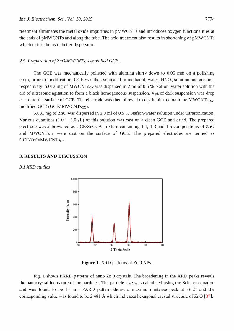
Figure 1. XRD patterns of ZnO NPs.
Fig. 1 shows PXRD patterns of nano ZnO crystals. The broadening in the XRD peaks reveals
the nanocrystalline nature of the particles. The particle size was calculated using the Scherer equation
and was found to be 44 nm. PXRD pattern shows a maximum intense peak at 36.2° and the
corresponding value was found to be 2.481 Å which indicates hexagonal crystal structure of ZnO [37].
Int. J. Electrochem. Sci., Vol. 10, 2015
7775
3.2 UV-Visible Spectroscopy
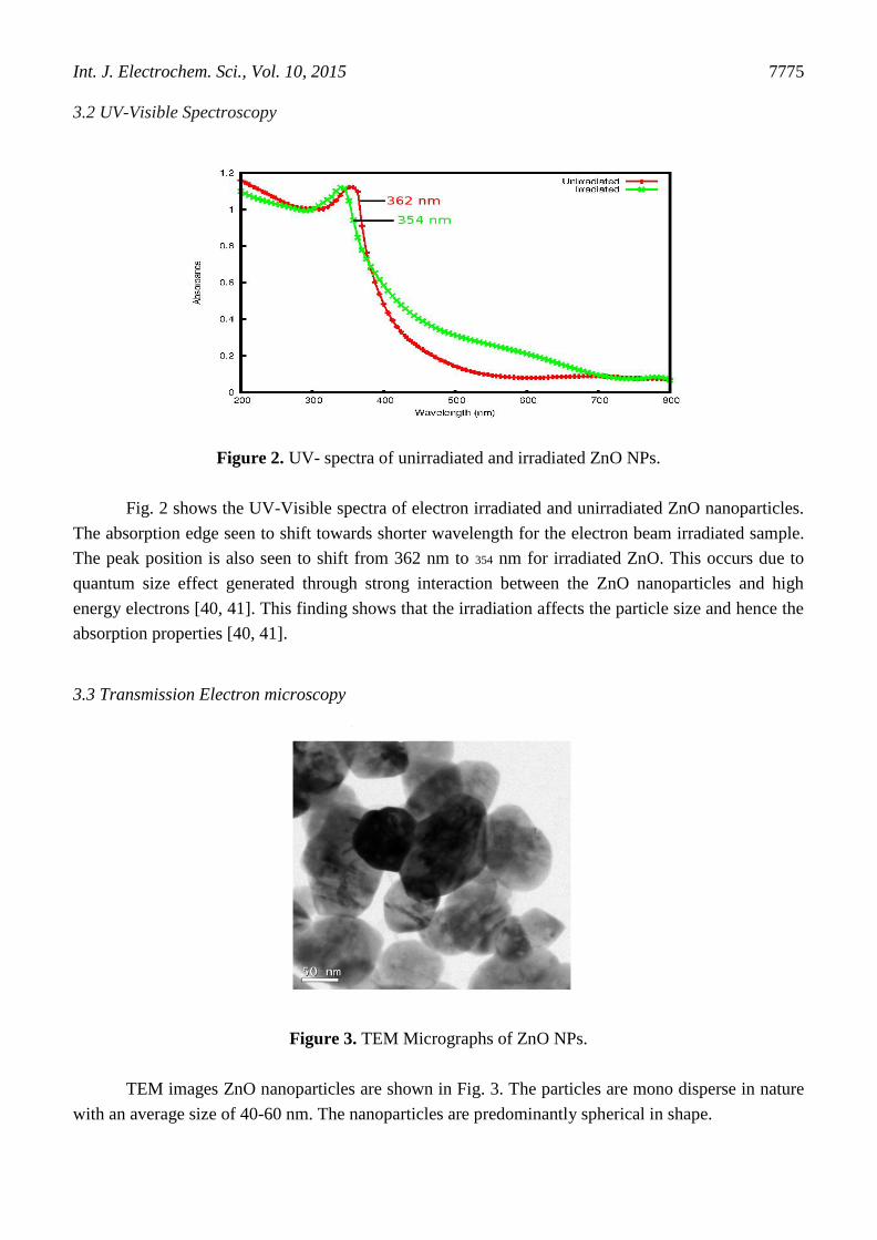
Figure 2. UV- spectra of unirradiated and irradiated ZnO NPs.
Fig. 2 shows the UV-Visible spectra of electron irradiated and unirradiated ZnO nanoparticles.
The absorption edge seen to shift towards shorter wavelength for the electron beam irradiated sample.
The peak position is also seen to shift from 362 nm to 354 nm for irradiated ZnO. This occurs due to
quantum size effect generated through strong interaction between the ZnO nanoparticles and high
energy electrons [40, 41]. This finding shows that the irradiation affects the particle size and hence the
absorption properties [40, 41].
3.3 Transmission Electron microscopy
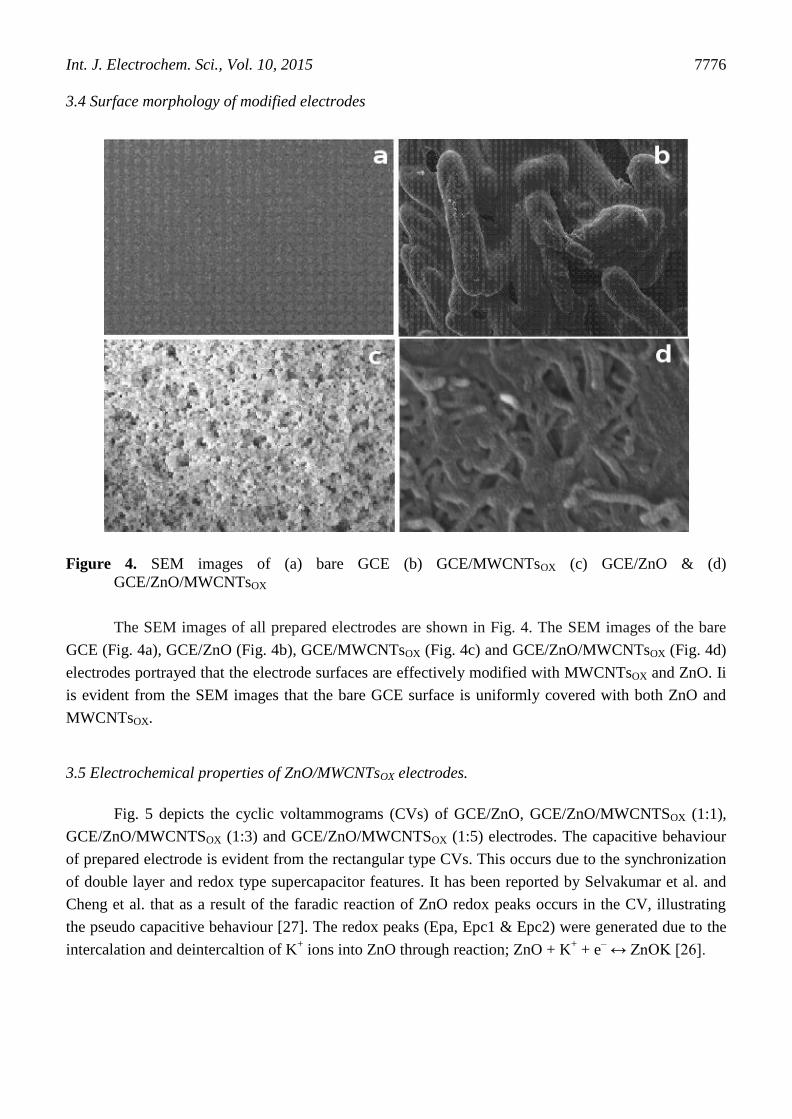
Figure 3. TEM Micrographs of ZnO NPs.
TEM images ZnO nanoparticles are shown in Fig. 3. The particles are mono disperse in nature
with an average size of 40-60 nm. The nanoparticles are predominantly spherical in shape.
Int. J. Electrochem. Sci., Vol. 10, 2015
7776
3.4 Surface morphology of modified electrodes
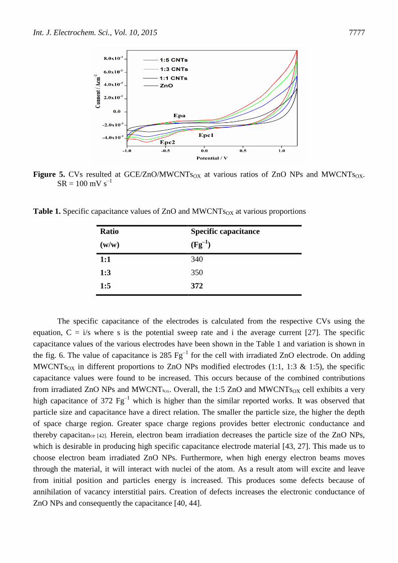
Figure 4. SEM images of (a) bare GCE (b) GCE/MWCNTsOX (c) GCE/ZnO & (d)
GCE/ZnO/MWCNTsOX
The SEM images of all prepared electrodes are shown in Fig. 4. The SEM images of the bare
GCE (Fig. 4a), GCE/ZnO (Fig. 4b), GCE/MWCNTsOX (Fig. 4c) and GCE/ZnO/MWCNTsOX (Fig. 4d)
electrodes portrayed that the electrode surfaces are effectively modified with MWCNTsOX and ZnO. Ii
is evident from the SEM images that the bare GCE surface is uniformly covered with both ZnO and
MWCNTsOX.
3.5 Electrochemical properties of ZnO/MWCNTsOX electrodes.
Fig. 5 depicts the cyclic voltammograms (CVs) of GCE/ZnO, GCE/ZnO/MWCNTSOX (1:1),
GCE/ZnO/MWCNTSOX (1:3) and GCE/ZnO/MWCNTSOX (1:5) electrodes. The capacitive behaviour
of prepared electrode is evident from the rectangular type CVs. This occurs due to the synchronization
of double layer and redox type supercapacitor features. It has been reported by Selvakumar et al. and
Cheng et al. that as a result of the faradic reaction of ZnO redox peaks occurs in the CV, illustrating
the pseudo capacitive behaviour [27]. The redox peaks (Epa, Epc1 & Epc2) were generated due to the
intercalation and deintercaltion of K+ ions into ZnO through reaction; ZnO + K
+ + e
– ↔ ZnOK [26].
Int. J. Electrochem. Sci., Vol. 10, 2015
7777
Figure 5. CVs resulted at GCE/ZnO/MWCNTsOX at various ratios of ZnO NPs and MWCNTsOX.
SR = 100 mV s–1
Table 1. Specific capacitance values of ZnO and MWCNTsOX at various proportions
Ratio
(w/w)
Specific capacitance
(Fg–1
)
1:1 340
1:3 350
1:5 372
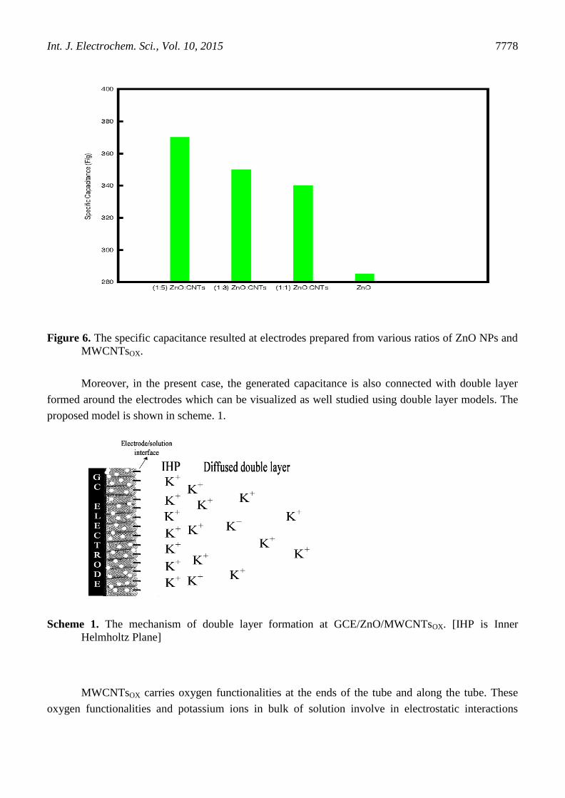
The specific capacitance of the electrodes is calculated from the respective CVs using the
equation, C = i/s where s is the potential sweep rate and i the average current [27]. The specific
capacitance values of the various electrodes have been shown in the Table 1 and variation is shown in
the fig. 6. The value of capacitance is 285 Fg–1
for the cell with irradiated ZnO electrode. On adding
MWCNTsOX in different proportions to ZnO NPs modified electrodes (1:1, 1:3 & 1:5), the specific
capacitance values were found to be increased. This occurs because of the combined contributions
from irradiated ZnO NPs and MWCNTsOX. Overall, the 1:5 ZnO and MWCNTsOX cell exhibits a very
high capacitance of 372 Fg–1
which is higher than the similar reported works. It was observed that
particle size and capacitance have a direct relation. The smaller the particle size, the higher the depth
of space charge region. Greater space charge regions provides better electronic conductance and
thereby capacitance [42]. Herein, electron beam irradiation decreases the particle size of the ZnO NPs,
which is desirable in producing high specific capacitance electrode material [43, 27]. This made us to
choose electron beam irradiated ZnO NPs. Furthermore, when high energy electron beams moves
through the material, it will interact with nuclei of the atom. As a result atom will excite and leave
from initial position and particles energy is increased. This produces some defects because of
annihilation of vacancy interstitial pairs. Creation of defects increases the electronic conductance of
ZnO NPs and consequently the capacitance [40, 44].
Int. J. Electrochem. Sci., Vol. 10, 2015
7778
Figure 6. The specific capacitance resulted at electrodes prepared from various ratios of ZnO NPs and
MWCNTsOX.
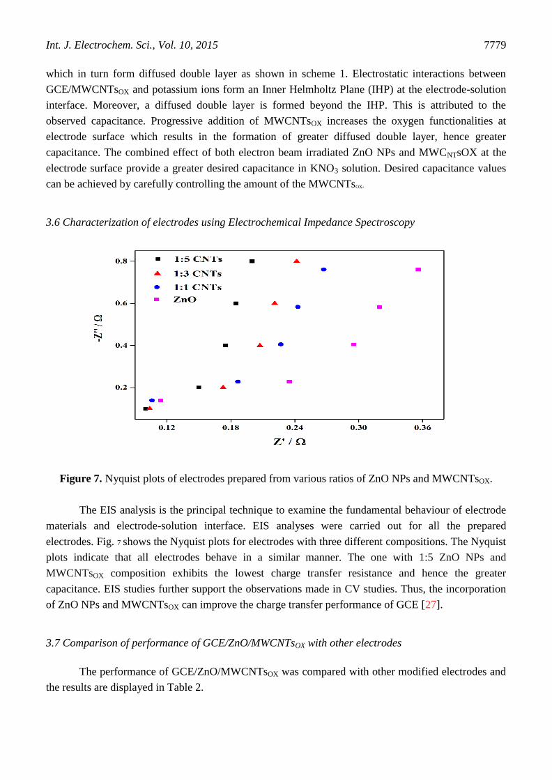
Moreover, in the present case, the generated capacitance is also connected with double layer
formed around the electrodes which can be visualized as well studied using double layer models. The
proposed model is shown in scheme. 1.
Scheme 1. The mechanism of double layer formation at GCE/ZnO/MWCNTsOX. [IHP is Inner
Helmholtz Plane]
MWCNTsOX carries oxygen functionalities at the ends of the tube and along the tube. These
oxygen functionalities and potassium ions in bulk of solution involve in electrostatic interactions
Int. J. Electrochem. Sci., Vol. 10, 2015
7779
which in turn form diffused double layer as shown in scheme 1. Electrostatic interactions between
GCE/MWCNTsOX and potassium ions form an Inner Helmholtz Plane (IHP) at the electrode-solution
interface. Moreover, a diffused double layer is formed beyond the IHP. This is attributed to the
observed capacitance. Progressive addition of MWCNTsOX increases the oxygen functionalities at
electrode surface which results in the formation of greater diffused double layer, hence greater
capacitance. The combined effect of both electron beam irradiated ZnO NPs and MWCNTsOX at the
electrode surface provide a greater desired capacitance in KNO3 solution. Desired capacitance values
can be achieved by carefully controlling the amount of the MWCNTsOX.
3.6 Characterization of electrodes using Electrochemical Impedance Spectroscopy
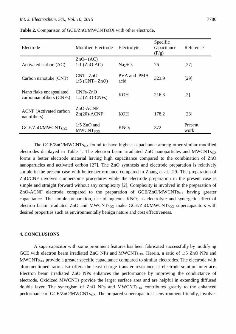
Figure 7. Nyquist plots of electrodes prepared from various ratios of ZnO NPs and MWCNTsOX.
The EIS analysis is the principal technique to examine the fundamental behaviour of electrode
materials and electrode-solution interface. EIS analyses were carried out for all the prepared
electrodes. Fig. 7 shows the Nyquist plots for electrodes with three different compositions. The Nyquist
plots indicate that all electrodes behave in a similar manner. The one with 1:5 ZnO NPs and
MWCNTsOX composition exhibits the lowest charge transfer resistance and hence the greater
capacitance. EIS studies further support the observations made in CV studies. Thus, the incorporation
of ZnO NPs and MWCNTsOX can improve the charge transfer performance of GCE [27].
3.7 Comparison of performance of GCE/ZnO/MWCNTsOX with other electrodes
The performance of GCE/ZnO/MWCNTsOX was compared with other modified electrodes and
the results are displayed in Table 2.
Int. J. Electrochem. Sci., Vol. 10, 2015
7780
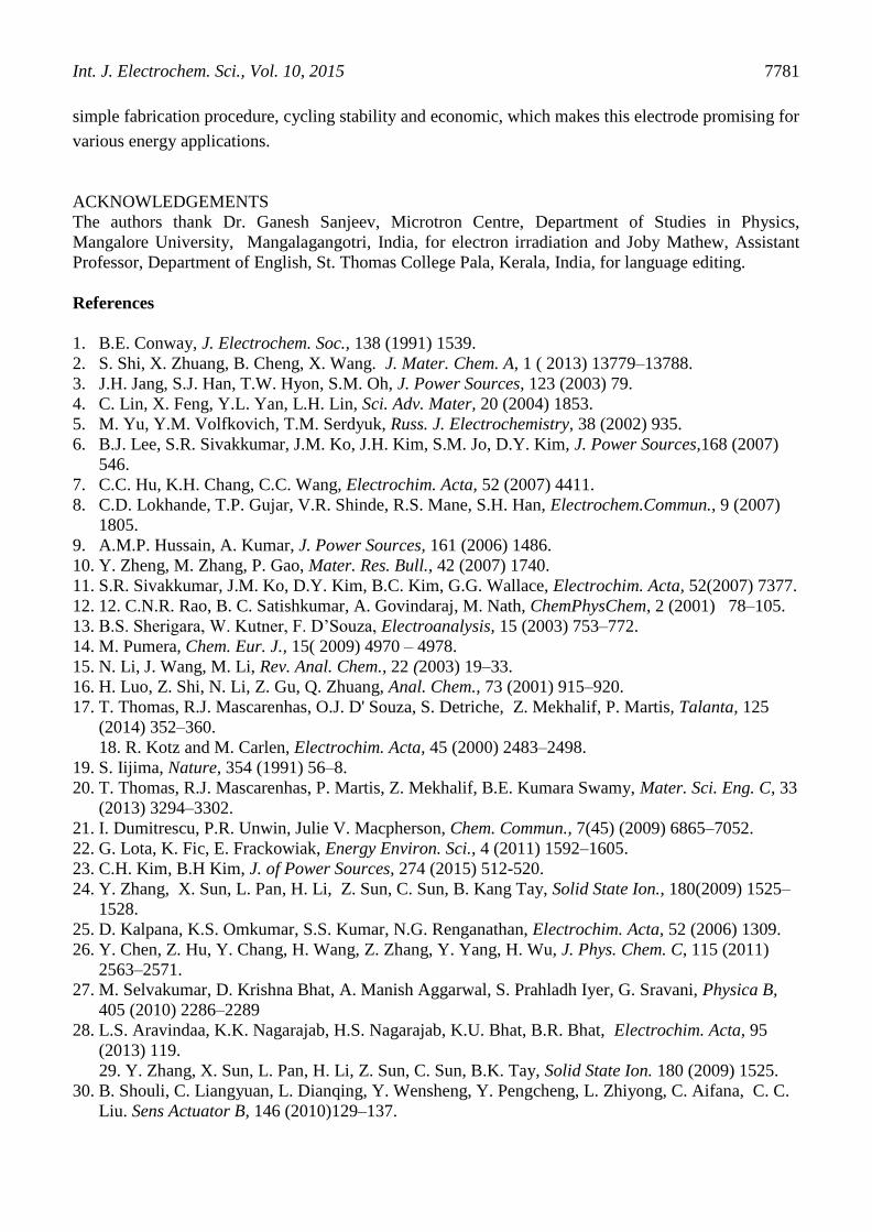
Table 2. Comparison of GCE/ZnO/MWCNTsOX with other electrode.
Electrode Modified Electrode Electrolyte
Specific
capacitance
(F/g)
Reference
Activated carbon (AC)
ZnO– (AC)
1:1 (ZnO:AC)
Na2SO4 76 [27]
Carbon nanotube (CNT) CNT– ZnO
1:5 (CNT– ZnO)
PVA and PMA
acid 323.9 [29]
Nano flake encapsulated
carbonnanofibers (CNFs)
CNFs-ZnO
1:2 (ZnO-CNFs) KOH 216.3 [2]
ACNF (Activated carbon
nanofibers)
ZnO-ACNF
Zn(20)-ACNF
KOH 178.2 [23]
GCE/ZnO/MWCNTSOX 1:5 ZnO and
MWCNTSOX KNO3 372
Present
work
The GCE/ZnO/MWCNTsOX found to have highest capacitance among other similar modified
electrodes displayed in Table 1. The electron beam irradiated ZnO nanoparticles and MWCNTsOX
forms a better electrode material having high capacitance compared to the combination of ZnO
nanoparticles and activated carbon [27]. The ZnO synthesis and electrode preparation is relatively
simple in the present case with better performance compared to Zhang et al. [29] The preparation of
ZnO/CNF involves cumbersome procedures while the electrode preparation in the present case is
simple and straight forward without any complexity [2]. Complexity is involved in the preparation of
ZnO-ACNF electrode compared to the preparation of GCE/ZnO/MWCNTsOX having greater
capacitance. The simple preparation, use of aqueous KNO3 as electrolyte and synergetic effect of
electron beam irradiated ZnO and MWCNTsOX make GCE/ZnO/MWCNTsOX supercapacitors with
desired properties such as environmentally benign nature and cost effectiveness.
4. CONCLUSIONS
A supercapacitor with some prominent features has been fabricated successfully by modifying
GCE with electron beam irradiated ZnO NPs and MWCNTsOX. Herein, a ratio of 1:5 ZnO NPs and
MWCNTsOX provide a greater specific capacitance compared to similar electrodes. The electrode with
aforementioned ratio also offers the least charge transfer resistance at electrode-solution interface.
Electron beam irradiated ZnO NPs enhances the performance by improving the conductance of
electrode. Oxidized MWCNTs provide the larger surface area and are helpful in extending diffused
double layer. The synergism of ZnO NPs and MWCNTsOX contributes greatly to the enhanced
performance of GCE/ZnO/MWCNTsOX. The prepared supercapacitor is environment friendly, involves
Int. J. Electrochem. Sci., Vol. 10, 2015
7781
simple fabrication procedure, cycling stability and economic, which makes this electrode promising for
various energy applications.
ACKNOWLEDGEMENTS
The authors thank Dr. Ganesh Sanjeev, Microtron Centre, Department of Studies in Physics,
Mangalore University, Mangalagangotri, India, for electron irradiation and Joby Mathew, Assistant
Professor, Department of English, St. Thomas College Pala, Kerala, India, for language editing.
References
1. B.E. Conway, J. Electrochem. Soc., 138 (1991) 1539.
2. S. Shi, X. Zhuang, B. Cheng, X. Wang. J. Mater. Chem. A, 1 ( 2013) 13779–13788.
3. J.H. Jang, S.J. Han, T.W. Hyon, S.M. Oh, J. Power Sources, 123 (2003) 79.
4. C. Lin, X. Feng, Y.L. Yan, L.H. Lin, Sci. Adv. Mater, 20 (2004) 1853.
5. M. Yu, Y.M. Volfkovich, T.M. Serdyuk, Russ. J. Electrochemistry, 38 (2002) 935.
6. B.J. Lee, S.R. Sivakkumar, J.M. Ko, J.H. Kim, S.M. Jo, D.Y. Kim, J. Power Sources,168 (2007)
546.
7. C.C. Hu, K.H. Chang, C.C. Wang, Electrochim. Acta, 52 (2007) 4411.
8. C.D. Lokhande, T.P. Gujar, V.R. Shinde, R.S. Mane, S.H. Han, Electrochem.Commun., 9 (2007)
1805.
9. A.M.P. Hussain, A. Kumar, J. Power Sources, 161 (2006) 1486.
10. Y. Zheng, M. Zhang, P. Gao, Mater. Res. Bull., 42 (2007) 1740.
11. S.R. Sivakkumar, J.M. Ko, D.Y. Kim, B.C. Kim, G.G. Wallace, Electrochim. Acta, 52(2007) 7377.
12. 12. C.N.R. Rao, B. C. Satishkumar, A. Govindaraj, M. Nath, ChemPhysChem, 2 (2001) 78–105.
13. B.S. Sherigara, W. Kutner, F. D’Souza, Electroanalysis, 15 (2003) 753–772.
14. M. Pumera, Chem. Eur. J., 15( 2009) 4970 – 4978.
15. N. Li, J. Wang, M. Li, Rev. Anal. Chem., 22 (2003) 19–33.
16. H. Luo, Z. Shi, N. Li, Z. Gu, Q. Zhuang, Anal. Chem., 73 (2001) 915–920.
17. T. Thomas, R.J. Mascarenhas, O.J. D' Souza, S. Detriche, Z. Mekhalif, P. Martis, Talanta, 125
(2014) 352–360.
18. R. Kotz and M. Carlen, Electrochim. Acta, 45 (2000) 2483–2498.
19. S. Iijima, Nature, 354 (1991) 56–8.
20. T. Thomas, R.J. Mascarenhas, P. Martis, Z. Mekhalif, B.E. Kumara Swamy, Mater. Sci. Eng. C, 33
(2013) 3294–3302.
21. I. Dumitrescu, P.R. Unwin, Julie V. Macpherson, Chem. Commun., 7(45) (2009) 6865–7052.
22. G. Lota, K. Fic, E. Frackowiak, Energy Environ. Sci., 4 (2011) 1592–1605.
23. C.H. Kim, B.H Kim, J. of Power Sources, 274 (2015) 512-520.
24. Y. Zhang, X. Sun, L. Pan, H. Li, Z. Sun, C. Sun, B. Kang Tay, Solid State Ion., 180(2009) 1525–
1528.
25. D. Kalpana, K.S. Omkumar, S.S. Kumar, N.G. Renganathan, Electrochim. Acta, 52 (2006) 1309.
26. Y. Chen, Z. Hu, Y. Chang, H. Wang, Z. Zhang, Y. Yang, H. Wu, J. Phys. Chem. C, 115 (2011)
2563–2571.
27. M. Selvakumar, D. Krishna Bhat, A. Manish Aggarwal, S. Prahladh Iyer, G. Sravani, Physica B,
405 (2010) 2286–2289
28. L.S. Aravindaa, K.K. Nagarajab, H.S. Nagarajab, K.U. Bhat, B.R. Bhat, Electrochim. Acta, 95
(2013) 119.
29. Y. Zhang, X. Sun, L. Pan, H. Li, Z. Sun, C. Sun, B.K. Tay, Solid State Ion. 180 (2009) 1525.
30. B. Shouli, C. Liangyuan, L. Dianqing, Y. Wensheng, Y. Pengcheng, L. Zhiyong, C. Aifana, C. C.
Liu. Sens Actuator B, 146 (2010)129–137.
Int. J. Electrochem. Sci., Vol. 10, 2015
7782
31. H. Cao, Y.G. Zhao, S.T. Ho, E.W. Seelig, Q.H. Wang, R.P.H. Chang, Phys. Rev. Lett.,82 (1999)
2278–2281.
32. S. Stassinopoulos, R.N. Das, S.H. Anastasiadis, E.P. Giannelis, D. Anglos. J. Opt.,12 (2010)
024006-14 .
33. Z.L. Wang, J. Phys.: Condens. Matter., 16 (2004) R829–R858.
34. C.C. Chang, J.H. Chang, J. Mar. Sci. Technol., 4 (1996) 223–232.
35. S. Chu, M. Olmedo, Z. Yang, J. Kong, J. Liu, Appl. Phys. Lett., 93 (2008) 181106-9 .
36. J.C. Johnson, H. Yan, R.D. Schaller, L.H. Haber, R.J. Saykally, P. Yang, J. Phys. Chem. B, 105
(2001) 11387–11390.
37. D. Thomas, S. Augustine, J. Prakash, J. Optoelectronics and Biomedical Materials, 6(4) (2014)
101 – 110.
38. Sathish Reddy, B.E. Kumara Swamy, Umesh Chandra, B.S.Sherigara, H. Jayadevappa, Int. J.
Electrochem. Sci., 5 (2010) 10 - 17
39. S.C Tsang, Y.K Chen, P.J.E. Harris, M.L.H Green, Nature, 372 (1994) 159–162.
40. A.V. Krasheninnikov, F. Banhart, Nat. Mater., 6 (2007) 723-733.
41. K.B Sapnar, V.N Bhoraskar, S.D Dhole, Proceedings of 2011 Particle Accelerator Conference,
New York, NY, USA, THP020 (2011) 2166-2168.
42. M. Jayalakshmi, M. Mohan Rao, Kwang-Bum Kim, Int. J. Electrochem. Sci., 1 (2006) 324-333.
43. K. Siraj, Kashif Javaid, J.D. Pedarnig, M.A. Bodea, S. Naseem, J Alloy Compd., 563 (2013) 280–
284.
44. F. Banhart, Rep. Prog. Phys., 62 (1999) 1181–1221.
© 2015 The Authors. Published by ESG (www.electrochemsci.org). This article is an open access
article distributed under the terms and conditions of the Creative Commons Attribution license
(http://creativecommons.org/licenses/by/4.0/).