Embed Size (px)
Citation preview
USER MANUAL
Controller Extension Box
November 18, 2015 D-UM-CTLEX
Visit our website at www.dpstele.com for the latest PDF manual and FAQs.
© 2015 DPS Telecom
This document contains proprietary information which is protected by copyright. All rights are reserved. No part of thisdocument may be photocopied without prior written consent of DPS Telecom.
All software and manuals are copyrighted by DPS Telecom. Said software and manuals may not be reproduced, copied,transmitted or used to make a derivative work, by either mechanical, electronic or any other means in whole or in part, withoutprior written consent from DPS Telecom, except as required by United States copyright laws.
The material in this manual is for information purposes and is subject to change without notice. DPS Telecom shall not beliable for errors contained herein or consequential damages in connection with the furnishing, performance, or use of thismanual.
Notice
Revision History
November 18, 2015
November 21, 2012
Specs update
Initial Release
1
Controller Extension Box Overview1
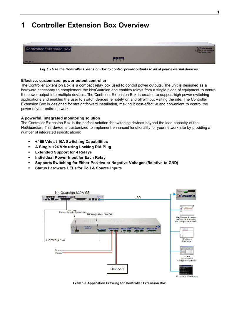
Fig. 1 - Use the Controller Extension Box to control power outputs to all of your external devices.
Effective, customized, power output controllerThe Controller Extension Box is a compact relay box used to control power outputs. The unit is designed as ahardware accessory to complement the NetGuardian and enables relays from a single piece of equipment to controlthe power output into multiple devices. The Controller Extension Box is created to support high power-switchingapplications and enables the user to switch devices remotely on and off without visiting the site. The ControllerExtension Box is designed for straightforward installation, making it cost-effective and convenient to control thepower of your entire network.
A powerful, integrated monitoring solutionThe Controller Extension Box is the perfect solution for switching devices beyond the load capacity of theNetGuardian. This device is customized to implement enhanced functionality for your network site by providing anumber of integrated specifications:
+/-60 Vdc at 10A Switching Capabilities
A Single +24 Vdc using Locking RIA Plug
Extended Support for 4 Relays
Individual Power Input for Each Relay
Supports Switching for Either Positive or Negative Voltages (Relative to GND)
Status Hardware LEDs for Coil & Source Inputs
Example Application Drawing for Controller Extension Box
2
Shipping List2
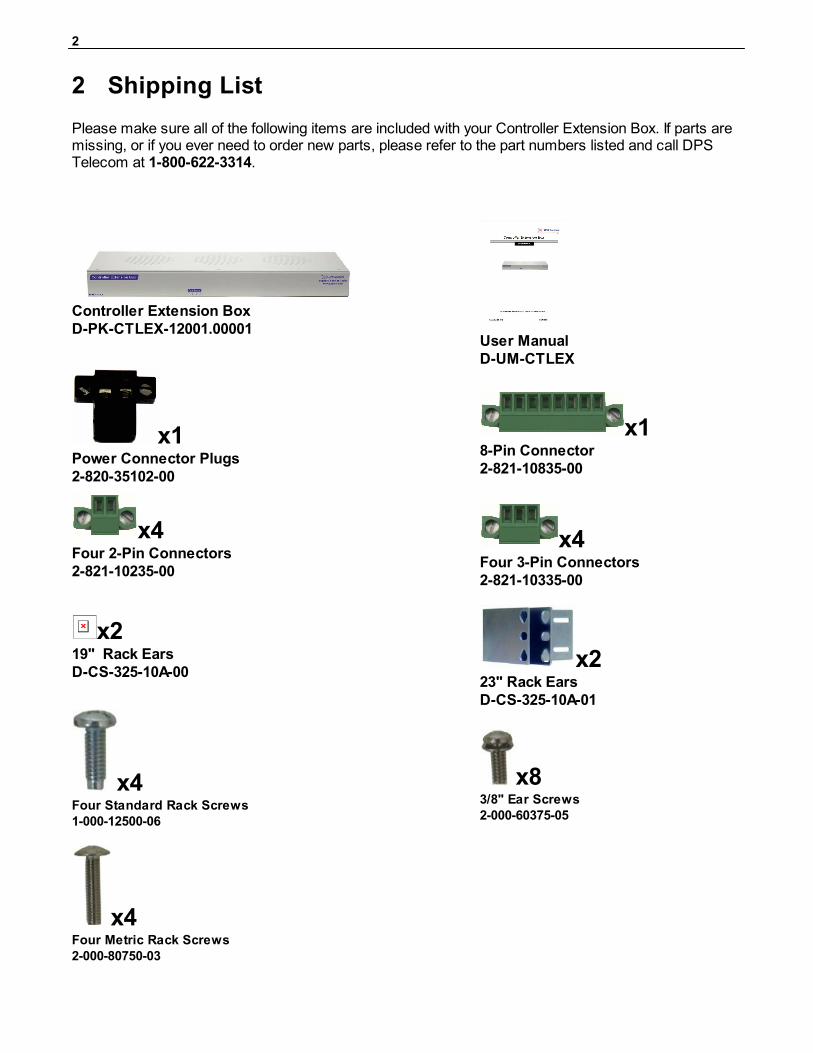
Please make sure all of the following items are included with your Controller Extension Box. If parts aremissing, or if you ever need to order new parts, please refer to the part numbers listed and call DPSTelecom at 1-800-622-3314.
Controller Extension BoxD-PK-CTLEX-12001.00001
User ManualD-UM-CTLEX
x1Power Connector Plugs2-820-35102-00
x18-Pin Connector2-821-10835-00
x4Four 2-Pin Connectors2-821-10235-00
x4Four 3-Pin Connectors2-821-10335-00
x219" Rack EarsD-CS-325-10A-00
x223" Rack EarsD-CS-325-10A-01
x4Four Standard Rack Screws1-000-12500-06
x83/8" Ear Screws2-000-60375-05
x4Four Metric Rack Screws2-000-80750-03
3
Specifications3
Dimensions: 1.7" H x 17.0" W x 4.34" D
Weight: 2.6 lbs.
Mounting: 19" or 23" rack or wall mount
Power Input: +24VDC (18 to 30VDC)
Output Relays: 2.5A max @ 50V continuous
Current Draw: 80mA @ +24VDC
Fuses: 1/2 Amp Resettable Fuse (Internal)
Visual Interface: 4 Front Panel LEDs
5 Back Panel LEDs
Operating Temperature: 32°–140° F (0°–60° C)
Operating Humidity: 0%–95% non-condensing
RoHS: 5/6
MTBF: 60 years
4
Installation4
Tools Needed4.1
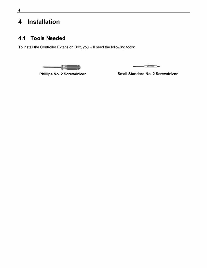
To install the Controller Extension Box, you will need the following tools:
Phillips No. 2 Screwdriver Small Standard No. 2 Screwdriver
5
Mounting4.2
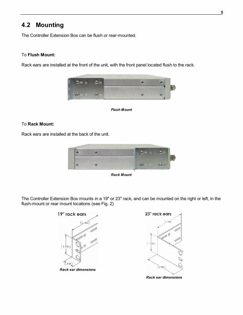
The Controller Extension Box can be flush or rear-mounted.
To Flush Mount:
Rack ears are installed at the front of the unit, with the front panel located flush to the rack.
Flush Mount
To Rack Mount:
Rack ears are installed at the back of the unit.
Rack Mount
The Controller Extension Box mounts in a 19" or 23" rack, and can be mounted on the right or left, in theflush-mount or rear mount locations (see Fig. 2)
Rack ear dimensions
Rack ear dimensions
6
Controller Extension Box Panels5
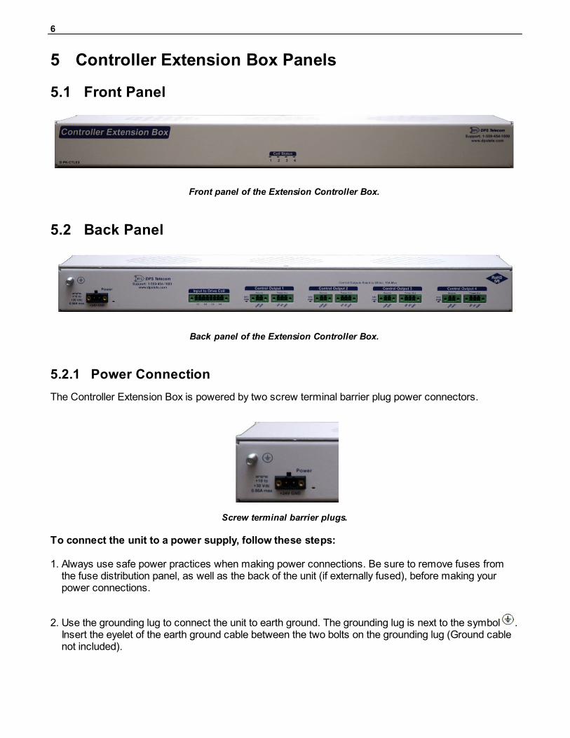
Front Panel5.1
Front panel of the Extension Controller Box.
Back Panel5.2
Back panel of the Extension Controller Box.
5.2.1 Power Connection
The Controller Extension Box is powered by two screw terminal barrier plug power connectors.
Screw terminal barrier plugs.
To connect the unit to a power supply, follow these steps:
1. Always use safe power practices when making power connections. Be sure to remove fuses fromthe fuse distribution panel, as well as the back of the unit (if externally fused), before making yourpower connections.
2. Use the grounding lug to connect the unit to earth ground. The grounding lug is next to the symbol .Insert the eyelet of the earth ground cable between the two bolts on the grounding lug (Ground cablenot included).
7
3. Insert a battery ground into the power connector plug's right terminal and tighten the screw; theninsert a battery line to the plug's left terminal and tighten its screw.
4. Insert a fuse into the fuse distribution panel and measure voltage. The voltmeter should read between+18 and +30VDC.
5. The power plug should be correctly inserted into the power connector to ensure the precise polarity.Note that the positive voltage terminal is on the left and the GND terminal is on the right.
6. Insert fuse into the Power A fuse slot (if externally fused). The power LED should be lit green.
7. Repeat steps 1 -6 for Power B connector (if dual power option).
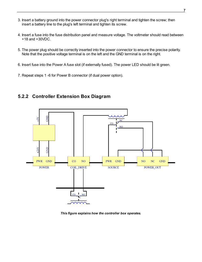
5.2.2 Controller Extension Box Diagram
This figure explains how the controller box operates.
8
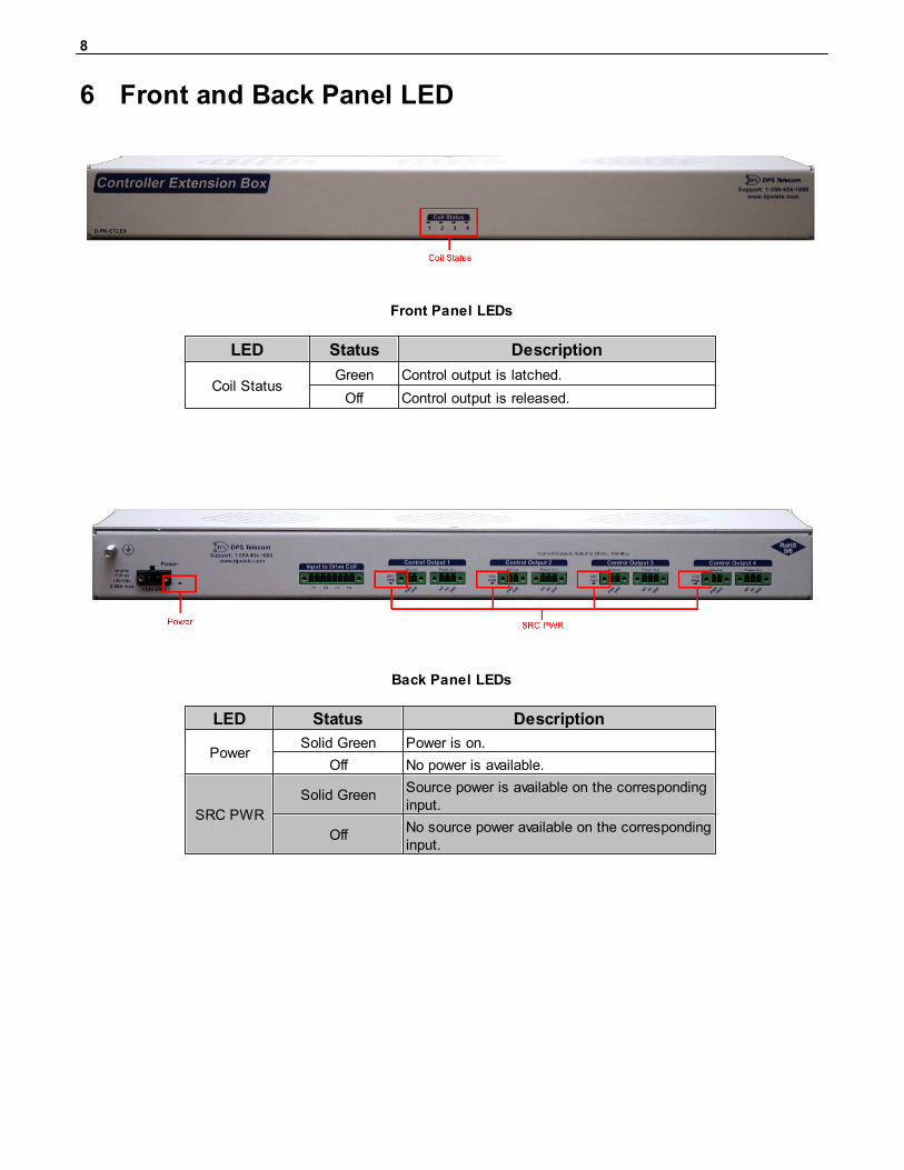
Front and Back Panel LED6
Front Panel LEDs
LED Status Description
Coil StatusGreen Control output is latched.
Off Control output is released.
Back Panel LEDs
LED Status Description
PowerSolid Green Power is on.
Off No power is available.
SRC PWR
Solid GreenSource power is available on the correspondinginput.
OffNo source power available on the correspondinginput.
9
Technical Support7
DPS Telecom products are backed by our courteous, friendly Technical Support representatives, whowill give you the best in fast and accurate customer service. To help us help you better, please take thefollowing steps before calling Technical Support:
1. Check the DPS Telecom website.
You will find answers to many common questions on the DPS Telecom website, at http://www.dpstele.com/support/. Look here first for a fast solution to your problem.
2. Prepare relevant information.
Having important information about your DPS Telecom product in hand when you call will greatlyreduce the time it takes to answer your questions. If you do not have all of the information when youcall, our Technical Support representatives can assist you in gathering it. Please write the informationdown for easy access. Please have your user manual and hardware serial number ready.
3. Have access to troubled equipment.Please be at or near your equipment when you call DPS Telecom Technical Support. This will help ussolve your problem more efficiently.
4. Call during Customer Support hours.Customer support hours are Monday through Friday, from 7 A.M. to 6 P.M., Pacific time. The DPSTelecom Technical Support phone number is (559) 454-1600.
Emergency Assistance: Emergency assistance is available 24 hours a day, 7 days a week. Foremergency assistance after hours, allow the phone to ring until it is answered with a paging message.You will be asked to enter your phone number. An on-call technical support representative will returnyour call as soon as possible.
10
End User License Agreement8
All Software and firmware used in, for, or in connection with the Product, parts, subsystems, or derivatives thereof,in whatever form, including, without limitation, source code, object code and microcode, including any computerprograms and any documentation relating to or describing such Software is furnished to the End User only under anon-exclusive perpetual license solely for End User's use with the Product.
The Software may not be copied or modified, in whole or in part, for any purpose whatsoever. The Software may notbe reverse engineered, compiled, or disassembled. No title to or ownership of the Software or any of its parts istransferred to the End User. Title to all patents, copyrights, trade secrets, and any other applicable rights shallremain with the DPS Telecom.
DPS Telecom's warranty and limitation on its liability for the Software is as described in the warranty informationprovided to End User in the Product Manual.
End User shall indemnify DPS Telecom and hold it harmless for and against any and all claims, damages, losses,costs, expenses, obligations, liabilities, fees and costs and all amounts paid in settlement of any claim, action orsuit which may be asserted against DPS Telecom which arise out of or are related to the non-fulfillment of anycovenant or obligation of End User in connection with this Agreement.
This Agreement shall be construed and enforced in accordance with the laws of the State of California, withoutregard to choice of law principles and excluding the provisions of the UN Convention on Contracts for theInternational Sale of Goods. Any dispute arising out of the Agreement shall be commenced and maintained only inFresno County, California. In the event suit is brought or an attorney is retained by any party to this Agreement toseek interpretation or construction of any term or provision of this Agreement, to enforce the terms of thisAgreement, to collect any money due, or to obtain any money damages or equitable relief for breach, the prevailingparty shall be entitled to recover, in addition to any other available remedy, reimbursement for reasonable attorneys'fees, court costs, costs of investigation, and other related expenses.

11
Notes9

12

“Your Part ners in Network Alarm Management ”
“Dependable, Powerful Solutionsthat allow users to monitor larger,more complicated networks with a
smaller, less trained staff”
www.dpstelecom.com4955 E Yale • Fresno, CA 93727
559-454-1600 • 800-622-3314 • 559-454-1688 fax