Embed Size (px)
Citation preview
WARNINGS AND CAUTIONS:• TO AVOID FIRE, SHOCK, OR DEATH; TURN OFF POWER AT CIRCUIT BREAKER OR FUSE AND TEST THAT THE POWER IS OFF BEFORE WIRING!• Tobeinstalledand/orusedinaccordancewithelectricalcodesandregulations.• Toavoidoverheatingandpossibledamagetothisdeviceandotherequipment,DO NOTinstalltocontrolareceptacle,amotor,oratransformer-operatedappliance
otherthanapplicablespecifiedlightingload:IncandescentandLED.• Whenusingina3-wayapplicationuseonesensorandonestandard3-wayswitch.Cannotbeusedwithanothersensor,orina4-wayapplication.
WARNINGS AND CAUTIONS:• Ifyouarenotsureaboutanypartoftheseinstructions,consultanelectrician.• Cleanoutersurfacegentlywithdampclothonly.DO NOT usesoapsorcleaningliquids.• Nouserserviceablecomponents.DO NOT attempttoserviceorrepair.• UsethisdeviceWITH COPPER OR COPPER CLAD WIRE ONLY.
RESETRESET
TESTTEST
1 2
0 3
Push down tabs per diagram, one at a time and rotate forward to release
1 2
0 3
1 2
0 3
Attach new face by inserting bottom hinge tabs, then pivot and snap the color kit to attach
TOOLS NEEDED TO INSTALL YOUR DEVICE
Slotted/PhillipsScrewdriver ElectricalTape PliersPencil Cutters Ruler
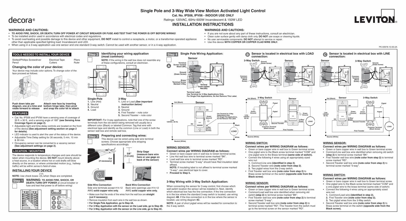
Changing the color of your device:Yourdevicemayincludecoloroptions.Tochangecolorofthefaceproceedasfollows:
BK
RD3-Way
TerminalScrew marked
Red (RD)
2
TerminalScrew marked
Black (BK)
BrassTerminal Screw
Marked 3-Way
Terminal Label:Use Terminal for 3-Way Applications Only.For Single Pole Applications, Do Not Remove This Label.
4
1
3
Ground(Green Screw)
Sensor
Single Pole and 3-Way Wide View Motion Activated Light ControlCat. No. IPS06, IPV06 - INDOOR USE ONLY
Ratings:120VAC,60Hz600WIncandescent&150WLED
INSTALLATION INSTRUCTIONS
PK-93978-10-00-2A
FEATURES• Cat.No.IPS06andIPV06haveasensingareaofcoverageof
30ft.x30ft.,andasensingangleof180O (see Sensing Area Coverage figure on page 2).
• Adjustablelightandtime-delaycontrolsarelocatedonthefrontofthedevice(See adjustment setting section on page 2 for details).
• LEDindicatorisusedtoalerttheuserofthestatusofthedevice.• AdjustableTimeDelaysettingfor30seconds,5min,15min
&30min.• Occupancysensorcanbeconvertedtoavacancysensor
(See adjustment settings on page 2).
LOCATION / MOUNTINGThedevicerespondstotemperaturechangesandcareshouldbetakenwhenmountingthedevice.DO NOTmountdirectlyaboveaheatsource,inalocationwherehotorcolddraftswillblowdirectlyonthesensor,orwhereunintendedmotion(e.g.,hallwaytraffic)willbewithinsensor’sfield-of-view.
Sensor is located in electrical box with LINE connection:C
Hot (Black)
Neutral (White)
BK
LOAD
Line120VAC60 Hz
Sensor
GreenGround
3-Way/Brass
3-Way Switch
Common Terminal(Black Screw)
Pigtail
PigtailGreenGround
RD
First Traveler
Second Traveler
Hot (Black)
Neutral (White)
BK
LOAD
Line120VAC60 Hz
Sensor
GreenGround
GreenGround
3-Way/Brass
3-Way Switch
Common Terminal(Black Screw)
Pigtail
Pigtail
First Traveler
Second TravelerRD
BK
RD3-Way
2
3-Way Switch
2
Sensor
1
3
5
CommonTerminal
(BlackScrew)
Ground(Green Screw)
1
4
43
5
CommonTerminal
(BlackScrew)
Ground(Green Screw)
BK
RD3-Way
2
Sensor
3
5
1
4
3-Way Switch
21
5
4
3
B Sensor is located in electrical box with LOAD connection:
WIRING SWITCH:Connect wires per WIRING DIAGRAM as follows:• GreenorbarecopperwireinwallboxtoGreenterminalscrew.• OnepigtailwiretotheBlackscrewterminalmarked"COM"and
onepigtailwiretotheBrassterminal(same side of switch).• Connectthefollowing4wiresusinganappropriatelysized
wirenut: 1. Common/Linewire(identified in step 2). 2. SecondTravelerwire(note color from step 2). 3. Twopigtailwiresfromthe3-wayswitch.• FirstTravelerwallboxwire(note color from step 2)to
Brassscrewterminalontheswitch(opposite side from the Black screw).
WIRING SENSOR:Connect wires per WIRING DIAGRAM as follows:• GreenorbarecopperwireinwallboxtoGreenterminalscrew.• Common/Loadwallboxwireidentifiedwhenremovingold
switch(step 2)toterminalscrewmarked"BK".• FirstTravelerwallboxwire(note color from step 2)toterminal
screwmarked"3-way".• SecondTravelerwallboxwire(note color from step 2)to
terminalscrewmarked"RD".ThisTravelerfromtheswitchmustgototheterminalscrewonthesensormarked"RD".
WIRING SENSOR:Connect wires per WIRING DIAGRAM as follows:• GreenorbarecopperwireinwallboxtoGreenterminalscrew.• Common/Linewallboxwireidentifiedwhenremovingoldswitch
(step 2)toterminalscrewmarked"BK".• FirstTravelerwallboxwire(note color from step 2)toterminal
screwmarked"RD".• SecondTravelerwallboxwire(note color from step 2)to
terminalscrewmarked"3-way".
WIRING SWITCH:Connect wires per WIRING DIAGRAM as follows:• GreenorbarecopperwireinwallboxtoGreenterminalscrew.• OnepigtailwiretotheBlackscrewterminalmarked"COM"and
aonepigtailwiretothebrassterminal(samesideofswitch)• Connectthefollowing4wiresusinganappropriatelysized
wirenut: 1. Common/Loadwire(identified in step 2). 2. FirstTravelerwire(note color from step 2). 3. Twopigtailwiresfromthe3-Wayswitch.• SecondTravelerwallboxwire(note color from step 2)to
Brassscrewterminalontheswitch(opposite side from the Black screw).
IMPORTANT:For3-wayapplications,notethatoneofthescrewterminalsfromtheoldswitchbeingremovedwillusuallybeadifferentcolor(Black)orlabeledCommon.Tagthatwirewithelectricaltapeandidentifyasthecommon(LineorLoad)inboththesensorwallboxandremotewallbox.
3-Way1. LineorLoad (See important
instruction below)2. Neutral3. Ground4. FirstTraveler–notecolor5. SecondTraveler–notecolor
2
4
3
1
Single-Pole1. Line(Hot)2. Neutral3. Ground4. Load
Step 2 Identifying your wiring application (most common):NOTE:Ifthewiringinthewallboxdoesnotresembleanyoftheseconfigurations,consultanelectrician.
Preparing and connecting wires:Thisdevicecanbewiredusingsidewireterminalscrews.Chooseappropriatewirestrippingspecificationsaccordingly.
• Makesurethattheendsofthewiresfromthewallboxarestraight (cut if necessary).
• Removeinsulationfromeachwireinthewallboxasshown.• For Single Pole Application, go to Step 4A.• For 3-Way Application with the sensor on the Load side, go to Step 4B.• For 3-Way Application with the sensor on the Line side, go to Step 4C.
Strip Gage (measure bare wire here or use gage on back of the sensor)
5/8”(1.6 cm)
Cut(if necessary)
Side Wire ConnectionSidewireterminalsaccept#14-12AWGsolid copper wire only.
Step 3
Back Wire Connection Backwireopeningsuse#14-12AWGsolid copper wire only.
BK
RDYL 3-Way
2
4
1
5
3
√INSTALLING YOUR DEVICE
NOTE: UsecheckboxeswhenStepsarecompleted.
ONOFF
ONOFF
ONOFF
ONOFF
ONOFF
ONOFF
ONOFFONOFF
ONOFF
ONOFF
ONOFF
ONOFF
Step 1 WARNING:TO AVOID FIRE, SHOCK, OR DEATH; TURN OFF POWERatcircuitbreakerorfuseandtestthatpowerisoffbeforewiring!
WIRING SENSOR:Connect wires per WIRING DIAGRAM as follows:• GreenorbarecopperwireinwallboxtoGreenterminalscrew.• LineHotwallboxwiretoterminalscrewmarked"BK".• Loadwallboxwiretoterminalscrewmarked"RD".• Terminalscrewmarked"3-way"shouldhaveRedinsulationlabel
affixed.NOTE: Ifinsulatinglabelisnotaffixedtoterminalscrewmarked"3-way",useelectricaltapetocover.
• ProceedtoStep5.
Use Terminal for 3-WayApplications Only.For Single Pole Applications,Do Not Remove This Label.
Hot (Black)
Neutral (White)
RDBlack
BK
White
LOAD
Line120VAC, 60 Hz
Sensor
GreenGround
3-Way(BrassScrew)
Step 4 Single Pole Wiring Application:
A
3-Way Wiring with 3-Way Switch Application:
Whenconnectingthesensorfor3-waycontrol,firstchoosewhichwallswitchlocationthesensorwillbeinstalledin.Next,identifywhichelectricalboxhasthelineconnection.Ifthelineconnectionisintheboxwherethestandard3-wayswitchislocated,usewiringdiagram4B.Ifthelineconnectionisintheboxwherethesensorislocated,usewiringdiagram4C.NOTE: Apairofshortpigtailwireswillbeneededforconnectiontothe3-wayswitch.
LIMITED 5 YEAR WARRANTY AND EXCLUSIONSLevitonwarrants to theoriginalconsumerpurchaserandnot for thebenefitofanyoneelse that thisproductat the timeof itssalebyLeviton is freeofdefects inmaterialsandworkmanshipundernormalandproperuse forfiveyears fromthepurchasedate.Leviton’sonlyobligation is tocorrectsuchdefectsby repairor replacement,at itsoption, ifwithinsuchfiveyearperiod theproduct is returnedprepaid,withproofofpurchasedate,andadescriptionof theproblemtoLeviton Manufacturing Co., Inc., Att: Quality Assurance Department, 201 North Service Road, Melville, New York 11747.Thiswarrantyexcludesand there isdisclaimed liability for labor for removalof thisproductor reinstallation.Thiswarranty isvoid if thisproduct is installed improperlyor inan improperenvironment,overloaded,misused,opened,abused,oraltered inanymanner,or isnotusedundernormaloperatingconditionsornot inaccordancewithany labelsor instructions.There are no other or implied warranties of any kind, including merchantability and fitness for a particular purpose, but if any impliedwarranty is requiredby theapplicable jurisdiction, thedurationofanysuch impliedwarranty, includingmerchantabilityandfitness foraparticularpurpose, is limited tofiveyears.Leviton is not liable for incidental, indirect, special, or consequential damages, including without limitation, damage to, or loss of use of, any equipment, lost sales or profits or delay or failure to perform this warranty obligation.The remediesprovidedhereinare theexclusive remediesunder thiswarranty,whetherbasedoncontract, tortorotherwise.
PK-93978-10-00-2A©2012LevitonMfg.Co.,Inc.
• Positionallwirestoprovideroominoutletwallboxfordevice.• Ensurethattheword"TOP"isfacingupondevicestrap.• Partiallyscrewinmountingscrewsinwallboxmountingholes.
• Restorepoweratcircuitbreakerorfuse.• ForIPS06lightswillautomaticallyturnON
afterpowerisapplied.• ForIPV06pressamdreleasepushpadto
turnthelightsON. See Locator Light Status chart to
confirm the operational state of the device.
If lights still do not turn ON, refer to the TROUBLESHOOTING section.
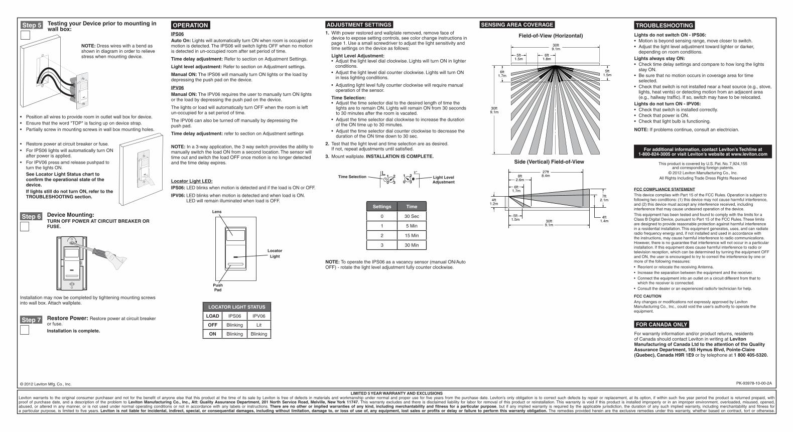
Testing your Device prior to mounting in wall box:
Step 5
Restore Power:Restorepoweratcircuitbreakerorfuse.
Installation is complete.
Step 7
Device Mounting:TURN OFF POWER AT CIRCUIT BREAKER OR FUSE.
Step 6
Installationmaynowbecompletedbytighteningmountingscrewsintowallbox.Attachwallplate.
OPERATION
Locator Light LED:IPS06:LEDblinkswhenmotionisdetectedandiftheloadisONorOFF.
IPV06: LEDblinkswhenmotionisdetectedandwhenloadisON.LEDwillremainilluminatedwhenloadisOFF.
NOTE: Dresswireswithabendasshownindiagraminordertorelievestresswhenmountingdevice.
For additional information, contact Leviton’s Techline at 1-800-824-3005 or visit Leviton’s website at www.leviton.com
ThisproductiscoveredbyU.S.Pat.No.7,924,155andcorrespondingforeignpatents.
©2012LevitonManufacturingCo.,Inc.AllRightsIncludingTradeDressRightsReserved
TROUBLESHOOTING
Lights do not switch ON - IPS06:• Motionisbeyondsensingrange,moveclosertoswitch.• Adjustthelightleveladjustmenttowardlighterordarker,
dependingonroomconditions.Lights always stay ON:• Checktimedelaysettingsandcomparetohowlongthelights
stayON.• Besurethatnomotionoccursincoverageareafortime
selected.• Checkthatswitchisnotinstallednearaheatsource(e.g.,stove,
lights,heatvents)ordetectingmotionfromanadjacentarea(e.g.,hallwaytraffic).Ifso,switchmayhavetoberelocated.
Lights do not turn ON - IPV06:• Checkthatswitchisinstalledcorrectly.• CheckthatpowerisON.• Checkthatlightbulbisfunctioning.
NOTE:Ifproblemscontinue,consultanelectrician.
ADJUSTMENT SETTINGS1. Withpowerrestoredandwallplateremoved,removefaceof
devicetoexposesettingcontrols,seecolorchangeinstructionsinpage1.Useasmallscrewdrivertoadjustthelightsensitivityandtimesettingsonthedeviceasfollows:
Light Level Adjustment: •Adjustthelightleveldialclockwise.LightswillturnONinlighter
conditions.•Adjustthelightleveldialcounterclockwise.LightswillturnON
inlesslightingconditions.
•Adjustinglightlevelfullycounterclockwisewillrequiremanualoperationofthesensor.
Time Selection:• Adjustthetimeselectordialtothedesiredlengthoftimethe
lightsaretoremainON.LightswillremainONfrom30secondsto30minutesaftertheroomisvacated.
• AdjustthetimeselectordialclockwisetoincreasethedurationoftheONtimeupto30minutes.
• AdjustthetimeselectordialcounterclockwisetodecreasethedurationoftheONtimedownto30sec.
2. Testthatthelightlevelandtimeselectionareasdesired.Ifnot,repeatadjustmentsuntilsatisfied.
3. Mountwallplate.INSTALLATION IS COMPLETE.
IPS06Auto On: LightswillautomaticallyturnONwhenroomisoccupiedormotionisdetected.TheIPS06willswitchlightsOFFwhennomotionisdetectedinun-occupiedroomaftersetperiodoftime.
Time delay adjustment:RefertosectiononAdjustmentSettings.
Light level adjustment:RefertosectiononAdjustmentsettings.
Manual ON: TheIPS06willmanuallyturnONlightsortheloadbydepressingthepushpadonthedevice.
IPV06Manual ON:TheIPV06requirestheusertomanuallyturnONlightsortheloadbydepressingthepushpadonthedevice.
ThelightsorloadwillautomaticallyturnOFFwhentheroomisleftun-occupiedforasetperiodoftime.
TheIPV06canalsobeturnedoffmanuallybydepressingthepushpad.
Time delay adjustment:refertosectiononAdjustmentsettings
Light Level Adjustment
Time Selection 1 2
0 3
1 2
0 3
Settings Time
0 30Sec
1 5Min
2 15Min
3 30Min
Push Pad
LOCATOR LIGHT STATUS
LOAD IPS06 IPV06
OFF Blinking Lit
ON Blinking Blinking
NOTE:Ina3-wayapplication,the3wayswitchprovidestheabilitytomanuallyswitchtheloadONfromasecondlocation.ThesensorwilltimeoutandswitchtheloadOFFoncemotionisnolongerdetectedandthetimedelayexpires.
SENSING AREA COVERAGE
Field-of-View (Horizontal)
Side (Vertical) Field-of-View
1.5m5ft
30ft9.1m
30ft9.1m
6ft1.7m
1.8m6ft
5ft1.5m
30ft9.1m
1.4m4ft
8.4m27ft
2.1m7ft
1.5m5ft
1.2m4ft
1.7m6ft
2.6m8ft
LocatorLight
Lens
FCC COMPLIANCE STATEMENTThisdevicecomplieswithPart15oftheFCCRules.Operationissubjecttofollowingtwoconditions:(1)thisdevicemaynotcauseharmfulinterference,and(2)thisdevicemustacceptanyinterferencereceived,includinginterferencethatmaycauseundesiredoperationofthedevice.ThisequipmenthasbeentestedandfoundtocomplywiththelimitsforaClassBDigitalDevice,pursuanttoPart15oftheFCCRules.Theselimitsaredesignedtoprovidereasonableprotectionagainstharmfulinterferenceinaresidentialinstallation.Thisequipmentgenerates,uses,andcanradiateradiofrequencyenergyand,ifnotinstalledandusedinaccordancewiththeinstructions,maycauseharmfulinterferencetoradiocommunications.However,thereisnoguaranteethatinterferencewillnotoccurinaparticularinstallation.Ifthisequipmentdoescauseharmfulinterferencetoradioortelevisionreception,whichcanbedeterminedbyturningtheequipmentOFFandON,theuserisencouragedtotrytocorrecttheinterferencebyoneormoreofthefollowingmeasures:•ReorientorrelocatethereceivingAntenna.•Increasetheseparationbetweentheequipmentandthereceiver.•Connecttheequipmentintoanoutletonacircuitdifferentfromthatto
whichthereceiverisconnected.•Consultthedealeroranexperiencedradio/tvtechnicianforhelp.
FCC CAUTIONAnychangesormodificationsnotexpresslyapprovedbyLevitonManufacturingCo.,Inc.,couldvoidtheuser'sauthoritytooperatetheequipment.
NOTE: TooperatetheIPS06asavacancysensor(manualON/AutoOFF)-rotatethelightleveladjustmentfullycounterclockwise.
FOR CANADA ONLY
Forwarrantyinformationand/orproductreturns,residentsofCanadashouldcontactLevitoninwritingatLeviton Manufacturing of Canada Ltd to the attention of the Quality Assurance Department, 165 Hymus Blvd, Pointe-Claire (Quebec), Canada H9R 1E9orbytelephoneat1 800 405-5320.