Embed Size (px)
Citation preview

1
New Product
DIN Track Terminal Blocks with Screw TerminalsXW5T
Global-standard DIN Terminal Blocks for Control Panels• Wires held with screws.• Compatible with a wide range of wire sizes with a nominal cross
section from 2.5 to 150 mm2.• Terminal Blocks with Fuses and Disconnect Terminal
Blocks are available.
Model Number Legend
Refer to Safety Precautions on page 20.
Refer to your OMRON website for the most recent information on models that are certified for standards.
XW5T - S@-@-@@ XW5G - S@-@-@Feed Through Terminal Blocks Grounding Terminal Blocks
(1) (2) (3) (1) (2) (3)(4)
(2) Wiring1.1:1:1
1.2:1:2
2.2:2:2
(3) Number of Tiers1: 1 tier2: 2 tiers
(1) Nominal Cross Section2.5: 2.5mm2
4.0: 4.0mm2
6.0: 6.0mm2
10: 10mm2
16: 16mm2
35: 35mm2
70: 70mm2
150: 150mm2
(4) ColorBlank: Dark grayBL: BlueV: Black (Vertical Connection)

XW5T
2
Ordering Information
Classification Product Type Nominal Cross Section (mm2)
Number of levels
Number of cramp position
per levelColer Insulating
material
Flammability Rating according
to UL94Model Pack
(pcs.)Weight(gram)
Feed ThroughTerminal blocks
Standard terminals
2.5 1 2 Dark gray PA V0 XW5T-S2.5-1.1-1 100 8
2.5 1 2 Blue PA V0 XW5T-S2.5-1.1-1BL 100 8
4.0 1 2 Dark gray PA V0 XW5T-S4.0-1.1-1 100 9
4.0 1 2 Blue PA V0 XW5T-S4.0-1.1-1BL 100 9
6.0 1 2 Dark gray PA V0 XW5T-S6.0-1.1-1 100 14
6.0 1 2 Blue PA V0 XW5T-S6.0-1.1-1BL 100 14
10.0 1 2 Dark gray PA V0 XW5T-S10-1.1-1 50 17
10.0 1 2 Blue PA V0 XW5T-S10-1.1-1BL 50 17
16.0 1 2 Dark gray PA V0 XW5T-S16-1.1-1 50 37
16.0 1 2 Blue PA V0 XW5T-S16-1.1-1BL 50 37
35.0 1 2 Dark gray PA V0 XW5T-S35-1.1-1 20 74
35.0 1 2 Blue PA V0 XW5T-S35-1.1-1BL 20 74
70.0 1 2 Dark gray PA V0 XW5T-S70-1.1-1 20 177
70.0 1 2 Blue PA V0 XW5T-S70-1.1-1BL 20 177
150.0 1 2 Dark gray PA V0 XW5T-S150-1.1-1 10 281
150.0 1 2 Blue PA V0 XW5T-S150-1.1-1BL 10 282
Multi tiers terminal
2.5 2 2 Dark gray PA V0 XW5T-S2.5-1.1-2 100 13
2.5 2 2 Black PA V0 XW5T-S2.5-1.1-2V 100 15
4.0 2 2 Dark gray PA V0 XW5T-S4.0-1.1-2 100 19
4.0 2 2 Black PA V0 XW5T-S4.0-1.1-2V 100 20
Multi conductor terminals
4.0 1 3Dark gray
PA V0 XW5T-S4.0-1.2-1 100 13
4.0 1 4 PA V0 XW5T-S4.0-2.2-1 100 17
4.0 1 3Blue
PA V0 XW5T-S4.0-1.2-1BL 100 13
4.0 1 4 PA V0 XW5T-S4.0-2.2-1BL 100 17
Grounding Terminal blocks
Standard terminals
2.5 1 2
Green/yellow
PA V0 XW5G-S2.5-1.1-1 100 10
4.0 1 2 PA V0 XW5G-S4.0-1.1-1 100 12
6.0 1 2 PA V0 XW5G-S6.0-1.1-1 100 20
10.0 1 2 PA V0 XW5G-S10-1.1-1 50 23
16.0 1 2 PA V0 XW5G-S16-1.1-1 50 47
35.0 1 2 PA V0 XW5G-S35-1.1-1 20 123
70.0 1 2 PA V0 XW5G-S70-1.1-1 20 240
Multi tiers terminal 4.0 2 2 PA V0 XW5G-S4.0-1.1-2 100 23
Multi conductor terminals
4.0 1 3 PA V0 XW5G-S4.0-1.2-1 100 16
4.0 1 4 PA V0 XW5G-S4.0-2.2-1 100 20
Special terminalsFuse terminal
4.0 1 2
Dark gray
PA V0 XW5T-S4.0-FU5 50 19
4.0 1 2 PA V0 XW5T-S4.0-FU6 50 22
Knife edge disconnect block 4.0 1 2 PA V0 XW5T-S4.0-KD 100 12

XW5T
3
AccessoriesShort BarsFor XW5-S2.5-
For XW5-S4.0-
For XW5-S6.0-
For XW5-S10-
For XW5-S16-
Cross Connector with ScrewFor XW5-S2.5-1.1-2
End Covers
Separator Plates
Labels
* Box including 250 pcs.
No. of poles Color Model Pack(pcs.)
2
Yellow (YL)
XW5S-S2.5-2 10
3 XW5S-S2.5-3 10
4 XW5S-S2.5-4 10
5 XW5S-S2.5-5 10
10 XW5S-S2.5-10 20
No. of poles Color Model Pack(pcs.)
2
Yellow (YL)
XW5S-S4.0-2 10
3 XW5S-S4.0-3 10
4 XW5S-S4.0-4 10
5 XW5S-S4.0-5 10
10 XW5S-S4.0-10 20
No. of poles Color Model Pack(pcs.)
2
Yellow (YL)
XW5S-S6.0-2 10
3 XW5S-S6.0-3 10
4 XW5S-S6.0-4 10
5 XW5S-S6.0-5 10
No. of poles Color Model Pack(pcs.)
2 Yellow (YL) XW5S-S10-2 10
No. of poles Color Model Pack(pcs.)
2 Yellow (YL) XW5S-S16-2 10
No. of poles Color Model Pack(pcs.)
2
Yellow (YL)
XW5S-S2.5-2N 10
3 XW5S-S2.5-3N 10
4 XW5S-S2.5-4N 10
5 XW5S-S2.5-5N 10
10 XW5S-S2.5-10N 10
Applicable Terminal Blocks Model Pack(pcs.)
XW5-S2.5-1.1-XW5-S4.0-1.1-XW5-S6.0-1.1-XW5-S10-1.1-
XW5E-S2.5 10
XW5T-S16-1.1- XW5E-S16 10
XW5T-S4.0-KDXW5-S4.0-1.2-1 XW5E-S4.0-1.2-1 10
XW5-S4.0-2.2-1 XW5E-S4.0-2.2-1 10
XW5-S4.0-1.1-2 XW5E-S4.0-1.1-2 10
XW5T-S2.5-1.1-2 XW5E-S2.5N 10
Applicable Terminal Blocks Model Pack(pcs.)
XW5-S2.5-1.1-XW5-S4.0-1.1-XW5-S6.0-1.1-XW5-S10-1.1-
XW5Z-S2.5PT 10
Applicable Terminal Blocks
Marking Model Pack(pcs.)
XW5-S2.5-
None XW5Z-S2.5LB 25
1-10 XW5Z-S2.5LB-1-10 25
11-20 XW5Z-S2.5LB-11-20 25
21-30 XW5Z-S2.5LB-21-30 25
31-40 XW5Z-S2.5LB-31-40 25
41-50 XW5Z-S2.5LB-41-50 25
51-60 XW5Z-S2.5LB-51-60 25
61-70 XW5Z-S2.5LB-61-70 25
71-80 XW5Z-S2.5LB-71-80 25
81-90 XW5Z-S2.5LB-81-90 25
91-100 XW5Z-S2.5LB-91-100 25
1-100 XW5Z-S2.5LB-1-100 1 *
XW5-S4.0-
None XW5Z-S4.0LB 25
1-10 XW5Z-S4.0LB-1-10 25
11-20 XW5Z-S4.0LB-11-20 25
21-30 XW5Z-S4.0LB-21-30 25
31-40 XW5Z-S4.0LB-31-40 25
41-50 XW5Z-S4.0LB-41-50 25
51-60 XW5Z-S4.0LB-51-60 25
61-70 XW5Z-S4.0LB-61-70 25
71-80 XW5Z-S4.0LB-71-80 25
81-90 XW5Z-S4.0LB-81-90 25
91-100 XW5Z-S4.0LB-91-100 25
1-100 XW5Z-S4.0LB-1-100 1 *
XW5-S6.0-
None XW5Z-S6.0LB 25
1-10 XW5Z-S6.0LB-1-10 25
11-20 XW5Z-S6.0LB-11-20 25
21-30 XW5Z-S6.0LB-21-30 25
31-40 XW5Z-S6.0LB-31-40 25
41-50 XW5Z-S6.0LB-41-50 25
51-60 XW5Z-S6.0LB-51-60 25
61-70 XW5Z-S6.0LB-61-70 25
71-80 XW5Z-S6.0LB-71-80 25
81-90 XW5Z-S6.0LB-81-90 25
91-100 XW5Z-S6.0LB-91-100 25
1-100 XW5Z-S6.0LB-1-100 1 *
XW5T
4
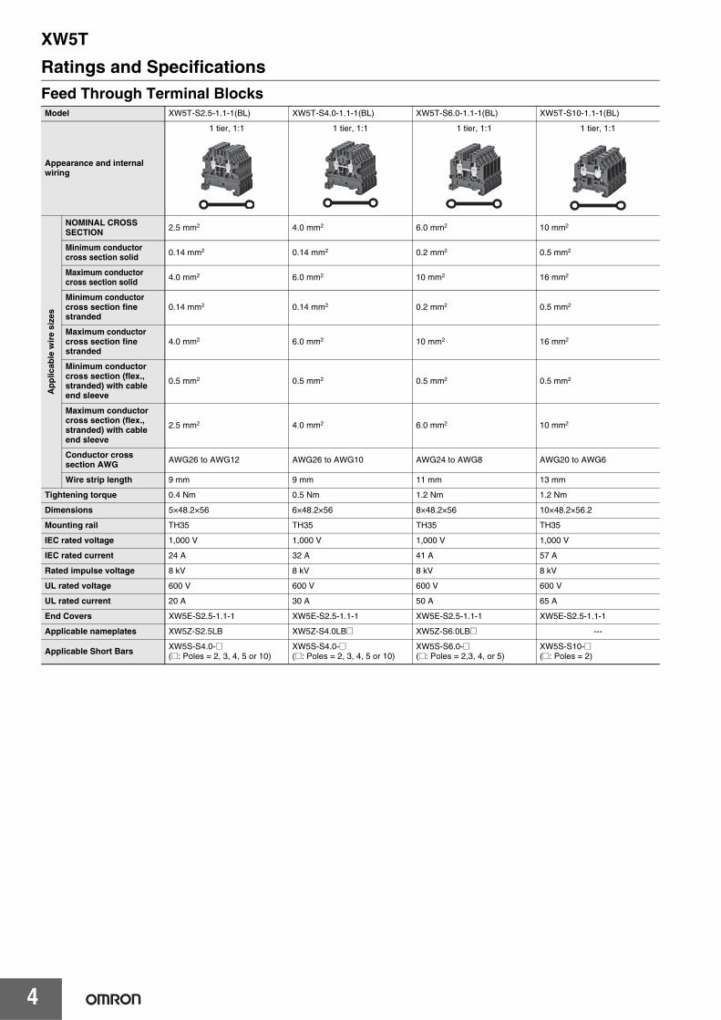
Ratings and SpecificationsFeed Through Terminal BlocksModel XW5T-S2.5-1.1-1(BL) XW5T-S4.0-1.1-1(BL) XW5T-S6.0-1.1-1(BL) XW5T-S10-1.1-1(BL)
Appearance and internal wiring
1 tier, 1:1 1 tier, 1:1 1 tier, 1:1 1 tier, 1:1
Ap
plic
able
wir
e si
zes
NOMINAL CROSS SECTION 2.5 mm2 4.0 mm2 6.0 mm2 10 mm2
Minimum conductor cross section solid 0.14 mm2 0.14 mm2 0.2 mm2 0.5 mm2
Maximum conductor cross section solid 4.0 mm2 6.0 mm2 10 mm2 16 mm2
Minimum conductor cross section fine stranded
0.14 mm2 0.14 mm2 0.2 mm2 0.5 mm2
Maximum conductor cross section fine stranded
4.0 mm2 6.0 mm2 10 mm2 16 mm2
Minimum conductor cross section (flex., stranded) with cable end sleeve
0.5 mm2 0.5 mm2 0.5 mm2 0.5 mm2
Maximum conductor cross section (flex., stranded) with cable end sleeve
2.5 mm2 4.0 mm2 6.0 mm2 10 mm2
Conductor cross section AWG AWG26 to AWG12 AWG26 to AWG10 AWG24 to AWG8 AWG20 to AWG6
Wire strip length 9 mm 9 mm 11 mm 13 mm
Tightening torque 0.4 Nm 0.5 Nm 1.2 Nm 1.2 Nm
Dimensions 5×48.2×56 6×48.2×56 8×48.2×56 10×48.2×56.2
Mounting rail TH35 TH35 TH35 TH35
IEC rated voltage 1,000 V 1,000 V 1,000 V 1,000 V
IEC rated current 24 A 32 A 41 A 57 A
Rated impulse voltage 8 kV 8 kV 8 kV 8 kV
UL rated voltage 600 V 600 V 600 V 600 V
UL rated current 20 A 30 A 50 A 65 A
End Covers XW5E-S2.5-1.1-1 XW5E-S2.5-1.1-1 XW5E-S2.5-1.1-1 XW5E-S2.5-1.1-1
Applicable nameplates XW5Z-S2.5LB XW5Z-S4.0LB@ XW5Z-S6.0LB@ ---
Applicable Short Bars XW5S-S4.0-@(@: Poles = 2, 3, 4, 5 or 10)
XW5S-S4.0-@ (@: Poles = 2, 3, 4, 5 or 10)
XW5S-S6.0-@ (@: Poles = 2,3, 4, or 5)
XW5S-S10-@ (@: Poles = 2)

XW5T
5
Feed Through Terminal BlocksModel XW5T-S16-1.1-1(BL) XW5T-S35-1.1-1(BL) XW5T-S70-1.1-1(BL) XW5T-S150-1.1-1(BL)
Appearance and internal wiring
1 tier, 1:1 1 tier, 1:1 1 tier, 1:1 1 tier, 1:1
Ap
plic
able
wir
e si
zes
NOMINAL CROSS SECTION 16 mm2 35 mm2 70 mm2 150 mm2
Minimum conductor cross section solid 1.5 mm2 10 mm2 --- ---
Maximum conductor cross section solid 16 mm2 10 mm2 --- ---
Minimum conductor cross section fine stranded
4.0 mm2 10 mm2 10 mm2 35 mm2
Maximum conductor cross section fine stranded
25 mm2 35 mm2 70 mm2 150 mm2
Minimum conductor cross section (flex., stranded) with cable end sleeve
1.5 mm2 --- --- ---
Maximum conductor cross section (flex., stranded) with cable end sleeve
16 mm2 --- --- ---
Conductor cross section AWG AWG14 to AWG4 AWG10 to AWG 1/0 AWG6 to AWG 2/0 AWG 2/0 to 350 kcmil
Wire strip length 15 mm 18 mm 24 mm 30 mm
Tightening torque 2 Nm 3 Nm 6 Nm 10 Nm
Dimensions 12×58.5×62 16×63×75.1 24×75.2×88.7 28×96×106.1
Mounting rail TH35 TH35 TH35 TH35
IEC rated voltage 1,000 V 800 V 800 V 1,000 V
IEC rated current 76 A 124 A 179 A 309 A
Rated impulse voltage 8 kV 8 kV 8 kV 8 kV
UL rated voltage 600 V 600 V 600 V 600 V
UL rated current 85 A 150 A 175 A 335 A
End Covers XW5E-S16
Applicable nameplates --- --- --- ---
Applicable Short Bars XW5S-S16-@ (@: Poles = 2) --- --- ---

XW5T
6
Feed Through Terminal BlocksModel XW5T-S2.5-1.1-2 XW5T-S2.5-1.1-2V XW5T-S4.0-1.2-1(BL)
Appearance and internal wiring
2 tiers, 2:2 2 tiers, 2:2 1 tier, 1:2
Ap
plic
able
wir
e si
zes
NOMINAL CROSS SECTION 2.5 mm2 2.5 mm2 4.0 mm2
Minimum conductor cross section solid 0.2 mm2 0.2 mm2 0.14 mm2
Maximum conductor cross section solid 4.0 mm2 4.0 mm2 6.0 mm2
Minimum conductor cross section fine stranded 0.14 mm2 0.14 mm2 0.14 mm2
Maximum conductor cross section fine stranded 2.5 mm2 2.5 mm2 6.0 mm2
Minimum conductor cross section (flex., stranded) with cable end sleeve --- --- 0.5 mm2
Maximum conductor cross section (flex., stranded) with cable end sleeve --- --- 4.0 mm2
Conductor cross section AWG AWG22 to AWG12 AWG22 to AWG12 AWG26 to AWG10
Wire strip length 8 mm 8 mm 9 mm
Tightening torque 0.4 Nm 0.4 Nm 0.5 Nm
Dimensions 5×65.8×71.4 5×65.8×71.4 6×58×56
Mounting rail TH35 TH35 TH35
IEC rated voltage 500 V 500 V 500 V
IEC rated current 24 A 24 A 32 A
Rated impulse voltage 6 kV 6 kV 6 kV
UL rated voltage 600 V 600 V 300 V
UL rated current 20 A 20 A 30 A
End Covers XW5E-S2.5N XW5E-S2.5N XW5E-S4.0-1.2-1
Applicable nameplates XW5Z-2.5LB@ XW5Z-2.5LB@ XW5Z-4.0LB@
Applicable Short Bars XW5S-S2.5-@N (@: Poles = 2, 3, 4, 5, or 10)
XW5S-S2.5-@N (@: Poles = 2, 3, 4, 5, or 10)
XW5S-S4.0-@ (@: Poles = 2, 3, 4, 5, or 10)

XW5T
7
Feed Through Terminal BlocksModel XW5T-S4.0-2.2-1(BL) XW5T-S4.0-1.1-2 XW5T-S4.0-1.1-2V
Appearance and internal wiring
1 tier, 2:2 2 tiers, 1:1 2 tiers, 1:1
Ap
plic
able
wir
e si
zes
NOMINAL CROSS SECTION 4.0 mm2 4.0 mm2 4.0 mm2
Minimum conductor cross section solid 0.14 mm2 0.14 mm2 0.14 mm2
Maximum conductor cross section solid 6.0 mm2 6.0 mm2 6.0 mm2
Minimum conductor cross section fine stranded 0.14 mm2 0.14 mm2 0.14 mm2
Maximum conductor cross section fine stranded 6.0 mm2 6.0 mm2 6.0 mm2
Minimum conductor cross section (flex., stranded) with cable end sleeve 0.5 mm2 0.5 mm2 0.5 mm2
Maximum conductor cross section (flex., stranded) with cable end sleeve 4.0 mm2 4.0 mm2 4.0 mm2
Conductor cross section AWG AWG26 to AWG10 AWG26 to AWG10 AWG26 to AWG10
Wire strip length 9 mm 9 mm 9 mm
Tightening torque 0.5 Nm 0.5 Nm 0.5 Nm
Dimensions 6×69×58 6×73×75 6×73×75
Mounting rail TH35 TH35 TH35
IEC rated voltage 500 V 800 V 800 V
IEC rated current 32 A 32 A 32 A
Rated impulse voltage 6 kV 8 kV 8 kV
UL rated voltage 300 V 300 V 300 V
UL rated current 30 A 30 A 30 A
End Covers XW5E-S4.0-2.2-1 XW5E-S4.0-1.1-2 XW5E-S4.0-1.1-2
Applicable nameplates XW5Z-4.0LB@ XW5Z-4.0LB@ XW5Z-4.0LB@
Applicable Short Bars XW5S-S4.0-@ (@: Poles = 2, 3, 4, 5, or 10)
XW5S-S4.0-@ (@: Poles = 2, 3, 4, 5, or 10)
XW5S-S4.0-@ (@: Poles = 2, 3, 4, 5, or 10)

XW5T
8
Grounding Terminal BlocksModel XW5G-S2.5-1.1-1 XW5G-S4.0-1.1-1 XW5G-S6.0-1.1-1 XW5G-S10-1.1-1
Appearance and internal wiring
1 tier, 1:1 1 tier, 1:1 1 tier, 1:1 1 tier, 1:1
App
licab
le w
ire
size
s
NOMINAL CROSS SECTION 2.5 mm2 4.0 mm2 6.0 mm2 10 mm2
Minimum conductor cross section solid 0.14 mm2 0.14 mm2 0.2 mm2 0.5 mm2
Maximum conductor cross section solid 4.0 mm2 6.0 mm2 10 mm2 16 mm2
Minimum conductor cross section fine stranded 0.14 mm2 0.14 mm2 0.2 mm2 0.5 mm2
Maximum conductor cross section fine stranded 4.0 mm2 6.0 mm2 10 mm2 16 mm2
Minimum conductor cross section (flex., stranded) with cable end sleeve 0.5 mm2 0.5 mm2 0.5 mm2 0.5 mm2
Maximum conductor cross section (flex., stranded) with cable end sleeve 2.5 mm2 4.0 mm2 6.0 mm2 10 mm2
Conductor cross section AWG AWG26 to AWG12 AWG26 to AWG10 AWG24 to AWG8 AWG20 to AWG6
Wire strip length 9 mm 9 mm 11 mm 13 mm
Tightening torque 0.4 Nm 0.5 Nm 1.2 Nm 1.2 Nm
Dimensions 5×48.2×56 6×48.2×56 8×48.2×56 10×48.2×56.2
Mounting rail TH35 TH35 TH35 TH35
IEC rated voltage 1,000 V 1,000 V 1,000 V 1,000 V
IEC rated current --- --- --- ---
Rated impulse voltage 8 kV 8 kV 8 kV 8 kV
UL rated voltage 600 V 600 V 600 V 600 V
UL rated current --- --- --- ---
End Covers XW5E-S2.5 XW5E-S2.5 XW5E-S2.5 XW5E-S2.5
Applicable nameplates XW5Z-S2.5LB@ XW5Z-S4.0LB@ XW5Z-S6.0LB@ ---
Applicable Short Bars --- --- --- ---

XW5T
9
Grounding Terminal BlocksModel XW5G-S16-1.1-1 XW5G-S35-1.1-1 XW5G-S70-1.1-1
Appearance and internal wiring
1 tier, 1:1 1 tier, 1:1 1 tier, 1:1
App
licab
le w
ire
size
s
NOMINAL CROSS SECTION 16 mm2 35 mm2 70 mm2
Minimum conductor cross section solid 1.5 mm2 10 mm2 ---
Maximum conductor cross section solid 16 mm2 35 mm2 ---
Minimum conductor cross section fine stranded 4.0 mm2 10 mm2 10 mm2
Maximum conductor cross section fine stranded 25 mm2 35 mm2 70 mm2
Minimum conductor cross section (flex., stranded) with cable end sleeve 1.5 mm2 --- ---
Maximum conductor cross section (flex., stranded) with cable end sleeve 16 mm2 --- ---
Conductor cross section AWG AWG14 to AWG4 AWG10 to AWG2 AWG6 to AWG 2/0
Wire strip length 15 mm 20 mm 24 mm
Tightening torque 2 Nm 3 Nm 6 Nm
Dimensions 12×58.5×62 16×63×75.1 24×75.2×88.7
Mounting rail TH35 TH35 TH35
IEC rated voltage 1000 V 800 V 800 V
IEC rated current --- --- ---
Rated impulse voltage 8 kV 8 kV 8 kV
UL rated voltage 600 V 600 V 600 V
UL rated current --- --- ---
End Covers XW5E-S16 --- ---
Applicable nameplates --- --- ---
Applicable Short Bars --- --- ---
XW5T
10
Grounding Terminal BlocksModel XW5G-S4.0-1.2-1 XW5G-S4.0-2.2-1 XW5G-S4.0-1.1-2
Appearance and internal wiring
1 tier, 1:2 1 tier, 2:2 2 tiers, 1:1
App
licab
le w
ire
size
s
NOMINAL CROSS SECTION 4.0 mm2 4.0 mm2 4.0 mm2
Minimum conductor cross section solid 0.14 mm2 0.14 mm2 0.14 mm2
Maximum conductor cross section solid 6 mm2 6 mm2 6 mm2
Minimum conductor cross section fine stranded 0.14 mm2 0.14 mm2 0.14 mm2
Maximum conductor cross section fine stranded 6 mm2 6 mm2 6 mm2
Minimum conductor cross section (flex., stranded) with cable end sleeve 0.5 mm2 0.5 mm2 0.5 mm2
Maximum conductor cross section (flex., stranded) with cable end sleeve 4 mm2 4 mm2 4 mm2
Conductor cross section AWG AWG26 to AWG10 AWG26 to AWG10 AWG26 to AWG10
Wire strip length 9 mm 9 mm 9 mm
Tightening torque 0.5 Nm 0.5 Nm 0.5 Nm
Dimensions 6×58×56 6×69×58 6×73×75
Mounting rail TH35 TH35 TH35
IEC rated voltage 500 V 500 V 800 V
IEC rated current --- --- ---
Rated impulse voltage 6 kV 6 kV 8 kV
UL rated voltage 300 V 300 V 300 V
UL rated current --- --- ---
End Covers XW5E-S4.0-1.2-1 XW5E-S4.0-2.2-1 XW5E-S4.0-1.1-2
Applicable nameplates XW5Z-4.0LB@ XW5Z-4.0LB@ XW5Z-4.0LB@
Applicable Short Bars --- --- ---
XW5T
11
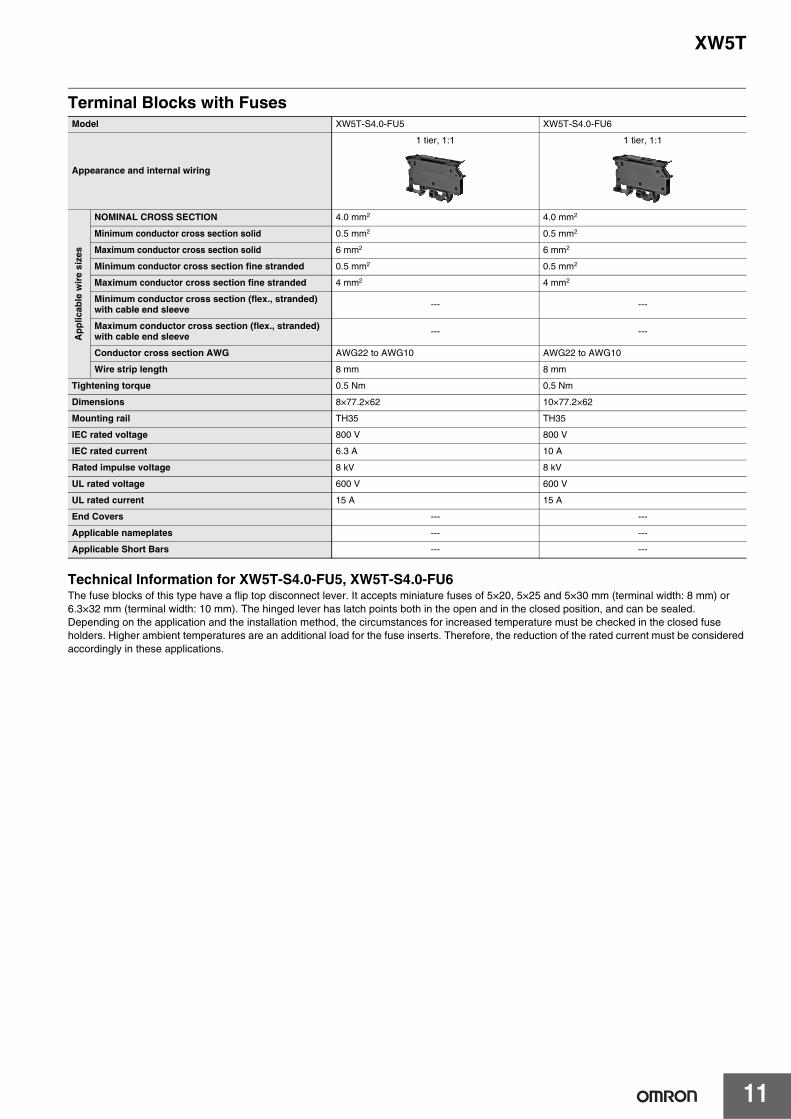
Terminal Blocks with Fuses
Technical Information for XW5T-S4.0-FU5, XW5T-S4.0-FU6The fuse blocks of this type have a flip top disconnect lever. It accepts miniature fuses of 5×20, 5×25 and 5×30 mm (terminal width: 8 mm) or 6.3×32 mm (terminal width: 10 mm). The hinged lever has latch points both in the open and in the closed position, and can be sealed. Depending on the application and the installation method, the circumstances for increased temperature must be checked in the closed fuse holders. Higher ambient temperatures are an additional load for the fuse inserts. Therefore, the reduction of the rated current must be considered accordingly in these applications.
Model XW5T-S4.0-FU5 XW5T-S4.0-FU6
Appearance and internal wiring
1 tier, 1:1 1 tier, 1:1
Ap
plic
able
wir
e si
zes
NOMINAL CROSS SECTION 4.0 mm2 4.0 mm2
Minimum conductor cross section solid 0.5 mm2 0.5 mm2
Maximum conductor cross section solid 6 mm2 6 mm2
Minimum conductor cross section fine stranded 0.5 mm2 0.5 mm2
Maximum conductor cross section fine stranded 4 mm2 4 mm2
Minimum conductor cross section (flex., stranded) with cable end sleeve --- ---
Maximum conductor cross section (flex., stranded) with cable end sleeve --- ---
Conductor cross section AWG AWG22 to AWG10 AWG22 to AWG10
Wire strip length 8 mm 8 mm
Tightening torque 0.5 Nm 0.5 Nm
Dimensions 8×77.2×62 10×77.2×62
Mounting rail TH35 TH35
IEC rated voltage 800 V 800 V
IEC rated current 6.3 A 10 A
Rated impulse voltage 8 kV 8 kV
UL rated voltage 600 V 600 V
UL rated current 15 A 15 A
End Covers --- ---
Applicable nameplates --- ---
Applicable Short Bars --- ---

XW5T
12
Disconnect Terminal Blocks
Short Bar
Characteristics
Model XW5T-S4.0-KD
Appearance and internal wiring
1 tier, 1:1
Ap
plic
able
wir
e si
zes
NOMINAL CROSS SECTION 4.0 mm2
Minimum conductor cross section solid 0.14 mm2
Maximum conductor cross section solid 6 mm2
Minimum conductor cross section fine stranded 0.14 mm2
Maximum conductor cross section fine stranded 6 mm2
Minimum conductor cross section (flex., stranded) with cable end sleeve 0.5 mm2
Maximum conductor cross section (flex., stranded) with cable end sleeve 4 mm2
Conductor cross section AWG AWG26 to AWG10
Wire strip length 9 mm
Tightening torque 0.5 Nm
Dimensions 6×58×58
Mounting rail TH35
IEC rated voltage 500 V
IEC rated current 20 A
Rated impulse voltage 6 kV
UL rated voltage 300 V
UL rated current 16 A
End Covers XW5E-S4.0-1.2-1
Applicable nameplates XW5Z-S4.0LB@
Applicable Short Bars XW5S-S4.0-@
Model XW5S-S2.5- XW5S-S4.0- XW5S-S6.0- XW5S-S10- XW5S-S16-
IEC rated voltage 600 V 1,000 V
IEC rated current 20 A 30 A 50 A 57 A 76 A
UL rated voltage 600 V
UL rated current 20 A 30 A 50 A 65 A 85 A
Compliant standardsUL
IEC60947-7-1
Operating temperature range -40 to 60°C (with no condensation or icing)
Insulating material PA
Flammability rating according to UL 94 V0
Operating humidity range 5% to 95%
Compliant standards cULus (UL 1059), IEC 60947-7-1 and IEC 60947-7-2
Vibration resistance 5 to 150 Hz 0.964 (m/s2)2/Hz
Shock resistance 50 m/s2 30 ms according EN 61373

XW5T
13
Dimensions (Unit: mm)
Feed Through Terminal Blocks
47.8
46.8
48.2
44
4156
48.6
42.2
5
Mounting rail EN 60715-35x15
Mounting rail EN 60715-35x7.5
XW5T-S2.5-1.1-1
48.2
44
48.647.8
5641
46.8
42.2
6
Mounting rail EN 60715-35x7.5
Mounting rail EN 60715-35x15
XW5T-S4.0-1.1-1
5648.6
47.8
42.2
46.8
41
48.2
8
44
Mounting railEN 60715-35x7.5
Mounting rail EN 60715-35x15
XW5T-S6.0-1.1-1
48.6
56.2
44
48.2
47.848.6
56.2
42.2
10
Mounting rail EN 60715-35x7.5
Mounting rail EN 60715-35x15
XW5T-S10-1.1-1
52.8
47
47.25
6254.5
53.7
58.5
57.5
12
Mounting rail EN 60715-35x7.5
Mounting rail EN 60715-35x15
XW5T-S16-1.1-1
13.85
63
27.9
29.335.4
67.669
75.1
16
Mounting rail EN 60715-35x7.5
Mounting rail EN 60715-35x15G-rail EN 60715-G32
XW5T-S35-1.1-1

XW5T
14
75.2
81.282.7
88.7
16.4
19.95
29.631.1
37.1
24
Mounting rail EN 60715-35x15G-rail EN 60715-G32
XW5T-S70-1.1-1
28
28.25
91.796
98.6100.1
27.3
33.3
25.8
106.1
Mouting rail EN 60715-35x7.5
Mounting rail EN 60715-35x15
G-rail EN 60715-G32
XW5T-S150-1.1-1
34
65.8
71.468.4
63.9
5
Mounting rail EN 60715-35x7.5
Mounting rail EN 60715-35x15
G-rail EN 60715-G32
XW5T-S2.5-1.1-2
42.2
4856
5658
47.8
43
48.8
6
Mounting rail EN 60715-35x7.5Mounting rail EN 60715-35x15
XW5T-S4.0-1.2-1
6
68
69
52.4
58
50
Mounting rail EN 60715-35x15
Mounting rail EN 60715-35x7.5
XW5T-S4.0-2.2-1
73
67
75
37.7
72
54.5
6
Mounting rail EN 60715-35x7.5
Mounting rail EN 60715-35x15
XW5T-S4.0-1.1-2

XW5T
15
Grounding Terminal Blocks
77.2
6259
54.5
56.6
8
G-rail EN 60715-G 32
Mounting rail EN 60715-35x15Mounting railEN 60715-35x7.5
XW5T-S4.0-FU5
6259
54.5
56.6
77.2
10
Mounting rail EN 60715-35x7.5Mounting rail EN 60715-35x15 G-rail EN 60715-G 32
XW5T-S4.0-FU6
56
58
42.2
5058
6
Mounting rail EN 60715-35x7.5
Mounting rail EN 60715-35x15
XW5T-S4.0-KD
47.8
46.8
48.2
44
4156
48.6
42.2
5
Mounting rail EN 60715-35x15
Mounting rail EN 60715-35x7.5
XW5G-S2.5-1.1-1
48.2
44
48.647.8
5641
46.8
42.2
6
Mounting rail EN 60715-35x7.5
Mounting rail EN 60715-35x15
XW5G-S4.0-1.1-1
5648.6
47.8
42.2
46.8
41
48.2
8
44
Mounting railEN 60715-35x7.5
Mounting rail EN 60715-35x15
XW5G-S6.0-1.1-110
5648.6
47.8
42.2
46.8
41
48.2
44
Mounting railEN 60715-35x7.5
Mounting rail EN 60715-35x15
XW5G-S10-1.1-1

XW5T
16
52.8
47
47.25
6254.5
53.7
58.5
57.5
12
Mounting rail EN 60715-35x7.5
Mounting rail EN 60715-35x15
XW5G-S16-1.1-1
13.85
63
27.9
29.335.4
67.669
75.1
16
Mounting rail EN 60715-35x7.5
Mounting rail EN 60715-35x15G-rail EN 60715-G32
XW5G-S35-1.1-1
75.2
81.282.7
88.7
16.4
19.95
29.631.1
37.1
24
Mounting rail EN 60715-35x15G-rail EN 60715-G32
XW5G-S70-1.1-1
42.2
48.656
56
58.6
47.8
43
48.8
6
Mounting rail EN 60715-35x7.5Mounting rail EN 60715-35x15
XW5G-S4.0-1.2-1
6
68
69
52.4
58
50
Mounting rail EN 60715-35x15
Mounting rail EN 60715-35x7.5
XW5G-S4.0-2.2-1
73
67
75
37.7
72
54.5
6
Mounting rail EN 60715-35x7.5
Mounting rail EN 60715-35x15
XW5G-S4.0-1.1-2

XW5T
17
Short Bars
Cross Connector with Screw
L
l
(2.1)
(14)
(23.9)
(1.65)
(5)
XW5S-S2.5-For XW5 -S2.5-
Model I (mm) L (mm)
XW5S-S2.5-2 5 10
XW5S-S2.5-3 10 15
XW5S-S2.5-4 15 20
XW5S-S2.5-5 20 25
XW5S-S2.5-10 45 50
L
l
6
23.9
1.75
14
2.4
XW5S-S4.0-For XW5 -S4.0-
Model I (mm) L (mm)
XW5S-S4.0-2 6 12
XW5S-S4.0-3 12 18
XW5S-S4.0-4 18 24
XW5S-S4.0-5 24 30
XW5S-S4.0-10 54 60
L
l
29.6
9
3
1.6
XW5S-S6.0-For XW5 -S6.0-
Model I (mm) L (mm)
XW5S-S6.0-2 8.2 14.7
XW5S-S6.0-3 16.4 22.9
XW5S-S6.0-4 24.6 31.1
XW5S-S6.0-5 32.8 39.3
15.2
17.8
35
10.2
4
2.4
XW5S-S10-2
12.2
18.5
35.8
20.55.4
3.6
XW5S-S16-2
9.1
0.8
5L
l5
M2.5
XW5S-S2.5- N For XW5 -S2.5-1.1-2Model I (mm) L (mm)
XW5S-S2.5-2N 5 8.9
XW5S-S2.5-3N 10 13.9
XW5S-S2.5-4N 15 18.9
XW5S-S2.5-5N 20 23.9
XW5S-S2.5-10N 45 48.9

XW5T
18
End Covers
Separator Plates
47
40.6
44
XW5E-S2.5
46.6
57.5
XW5E-S16
57.4
55.9
42.74240.7
XW5E-S4.0-1.2-1
67.8
40.642.6
XW5E-S4.0-2.2-1
59.5
35.4
72
37.7
XW5E-S4.0-1.1-2
62.5
33.8
32.1 33.7
53.2
XW5E-S2.5N
49
52.7
50.5
46.1
XW5Z-S2.5PT
XW5T
19
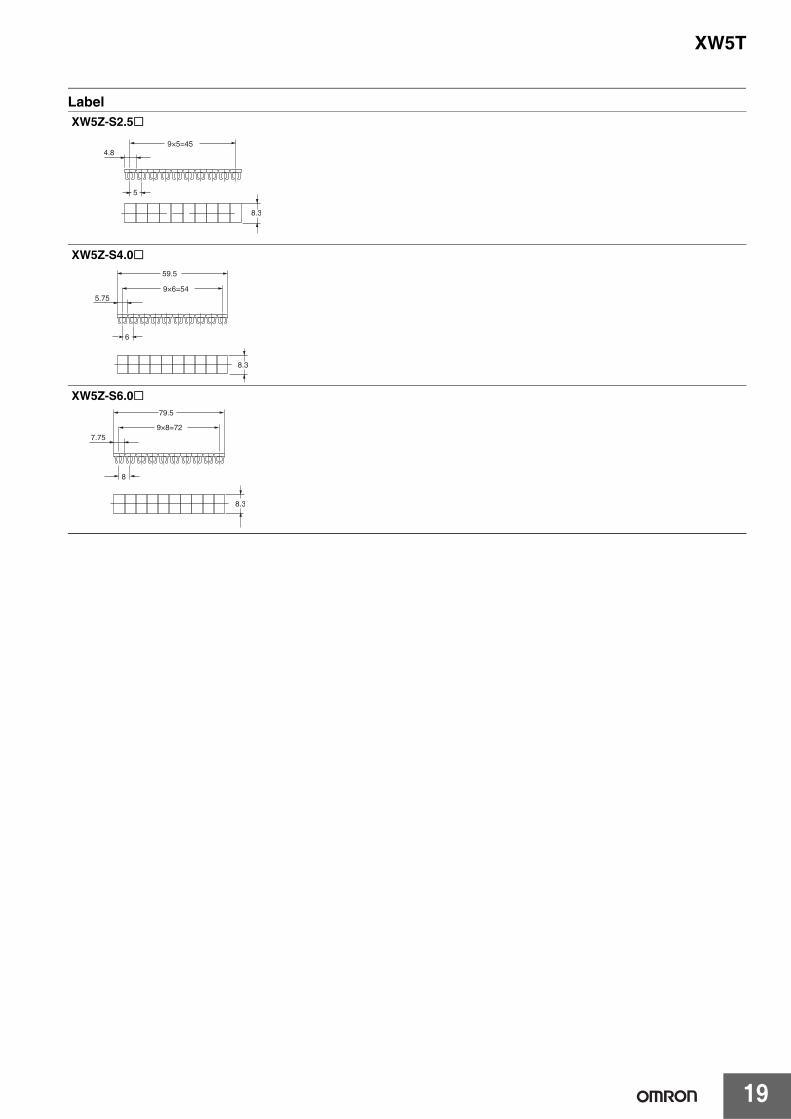
Label
4.8
5
8.3
9×5=45
XW5Z-S2.5
59.5
5.75
6
9×6=54
8.3
XW5Z-S4.0
79.5
7.75
8
9×8=72
8.3
XW5Z-S6.0

XW5T
20
Safety PrecautionsBe sure to read the precautions for all models in the website at the following URL: http://www.ia.omron.com/.Signal Word Definitions
• Do not bend a wire past its natural bending radius or pull on it with excessive force.Doing so may cause the wire disconnection.
• Do not insert more than one wire into each terminal insertion hole.• Before you start wiring, make sure that the Terminal Block is
securely attached and mounted to a DIN Track.If the Terminal Block is not stable, it may fall and possibly injure a worker.
• Do not install the Terminal Block upside down when mounting multiple Terminal Blocks.Doing so may cause short circuits with the adjacent Terminal Block.
1. Precautions for Correct Use• Do not drop the Terminal Block. Terminal Block functionality may
be inhibited.• Always attach End Cover. Not doing so may cause electrical
shock.• When you wire the Terminal Block, do not subject it or the wires to
stress. Secure the wires so that they do not resonate with vibrations from the facilities in installation conditions.
• Always turn OFF the power supply before wiring. Electrical shock may occur.
2. Connecting Wires to the Terminal Block
Wiring• Double-check all wiring before turning ON the power supply.• After wiring, route the cable so that force is not applied directly to
the connections.
Wires for Terminal Blocks• Do not damage the cores when stripping the insulation from them.• Always twist stranded wires together before connecting them.• Do not presolder wires. It may not be possible to connect them or
remove them.
Screw Tightening Torque and Applicable WiresWhen you connect wires to a Terminal Block, use the applicable wires and tightening torque given in the following table.
Wire Stripping LengthsIf you connect wires directly to the terminals, use the following stripping lengths.
3. Mounting to and Removing from DIN Track
Precautions for Safe Use
Supplementary comments on what to do or avoid doing, to use the product safely.
Precautions for Correct
Use
Supplementary comments on what to do or avoid doing, to prevent failure to operate, malfunction, or undesirable effects on product performance.
Precautions for Safe Use
Precautions for Correct Use
Model Wiring method
Tightening torque [N·m] (Use a flat-
blade screwdriver.)
Applicable wire sizes
Applicable wire sizes with ferrules attached
[email protected] M2.5 0.4 AWG26-AWG12 AWG20-AWG14
[email protected] M3 0.5 AWG26-AWG10 AWG20-AWG12
[email protected] M4 1.2 AWG24-AWG8 AWG20-AWG10
XW5@-S10 M4 1.2 AWG20-AWG6 AWG20-AWG8
XW5@-S16 M5 2 AWG12-AWG4 AWG12-AWG6
XW5@-S35 M6 2.5 AWG10-AWG1/0 AWG10-AWG2
XW5@-S70 M8 3.5 AWG6-AWG2/0 AWG6-AWG2/0
XW5@-S150 M10 4 AWG2/0-350kcmil AWG2/0-300kcmil
Model Stripping length [mm]
XW5@-S10 13
XW5@-S16 15
XW5@-S35 18
XW5@-S70 24
XW5@-S150 30
Mounting Procedure Removal Procedure
(1) Hook.
(2) Press.
1. Hook the Unit on the DIN Track.2. Press the Unit onto the DIN Track to
secure it.
1. Insert a flat-blade screwdriver into the DIN Track lock.
2. Move the screwdriver like a lever to free the lock.

Terms and Conditions AgreementRead and understand this catalog.
Please read and understand this catalog before purchasing the products. Please consult your OMRON representative if you have any questions or comments.
Warranties.(a) Exclusive Warranty. Omron’s exclusive warranty is that the Products will be free from defects in materials and workmanship
for a period of twelve months from the date of sale by Omron (or such other period expressed in writing by Omron). Omron disclaims all other warranties, express or implied.
(b) Limitations. OMRON MAKES NO WARRANTY OR REPRESENTATION, EXPRESS OR IMPLIED, ABOUT NON-INFRINGEMENT, MERCHANTABILITY OR FITNESS FOR A PARTICULAR PURPOSE OF THE PRODUCTS. BUYER ACKNOWLEDGES THAT IT ALONE HAS DETERMINED THAT THE PRODUCTS WILL SUITABLY MEET THE REQUIREMENTS OF THEIR INTENDED USE.
Omron further disclaims all warranties and responsibility of any type for claims or expenses based on infringement by the Products or otherwise of any intellectual property right. (c) Buyer Remedy. Omron’s sole obligation hereunder shall be, at Omron’s election, to (i) replace (in the form originally shipped with Buyer responsible for labor charges for removal or replacement thereof) the non-complying Product, (ii) repair the non-complying Product, or (iii) repay or credit Buyer an amount equal to the purchase price of the non-complying Product; provided that in no event shall Omron be responsible for warranty, repair, indemnity or any other claims or expenses regarding the Products unless Omron’s analysis confirms that the Products were properly handled, stored, installed and maintained and not subject to contamination, abuse, misuse or inappropriate modification. Return of any Products by Buyer must be approved in writing by Omron before shipment. Omron Companies shall not be liable for the suitability or unsuitability or the results from the use of Products in combination with any electrical or electronic components, circuits, system assemblies or any other materials or substances or environments. Any advice, recommendations or information given orally or in writing, are not to be construed as an amendment or addition to the above warranty.
See http://www.omron.com/global/ or contact your Omron representative for published information.
Limitation on Liability; Etc.OMRON COMPANIES SHALL NOT BE LIABLE FOR SPECIAL, INDIRECT, INCIDENTAL, OR CONSEQUENTIAL DAMAGES, LOSS OF PROFITS OR PRODUCTION OR COMMERCIAL LOSS IN ANY WAY CONNECTED WITH THE PRODUCTS, WHETHER SUCH CLAIM IS BASED IN CONTRACT, WARRANTY, NEGLIGENCE OR STRICT LIABILITY.
Further, in no event shall liability of Omron Companies exceed the individual price of the Product on which liability is asserted.
Suitability of Use.Omron Companies shall not be responsible for conformity with any standards, codes or regulations which apply to the combination of the Product in the Buyer’s application or use of the Product. At Buyer’s request, Omron will provide applicable third party certification documents identifying ratings and limitations of use which apply to the Product. This information by itself is not sufficient for a complete determination of the suitability of the Product in combination with the end product, machine, system, or other application or use. Buyer shall be solely responsible for determining appropriateness of the particular Product with respect to Buyer’s application, product or system. Buyer shall take application responsibility in all cases.
NEVER USE THE PRODUCT FOR AN APPLICATION INVOLVING SERIOUS RISK TO LIFE OR PROPERTY OR IN LARGE QUANTITIES WITHOUT ENSURING THAT THE SYSTEM AS A WHOLE HAS BEEN DESIGNED TO ADDRESS THE RISKS, AND THAT THE OMRON PRODUCT(S) IS PROPERLY RATED AND INSTALLED FOR THE INTENDED USE WITHIN THE OVERALL EQUIPMENT OR SYSTEM.
Programmable Products.Omron Companies shall not be responsible for the user’s programming of a programmable Product, or any consequence thereof.
Performance Data.Data presented in Omron Company websites, catalogs and other materials is provided as a guide for the user in determining suitability and does not constitute a warranty. It may represent the result of Omron’s test conditions, and the user must correlate it to actual application requirements. Actual performance is subject to the Omron’s Warranty and Limitations of Liability.
Change in Specifications.Product specifications and accessories may be changed at any time based on improvements and other reasons. It is our practice to change part numbers when published ratings or features are changed, or when significant construction changes are made. However, some specifications of the Product may be changed without any notice. When in doubt, special part numbers may be assigned to fix or establish key specifications for your application. Please consult with your Omron’s representative at any time to confirm actual specifications of purchased Product.
Errors and Omissions.Information presented by Omron Companies has been checked and is believed to be accurate; however, no responsibility is assumed for clerical, typographical or proofreading errors or omissions.

Authorized Distributor:
In the interest of product improvement, specifications are subject to change without notice.
Cat. No. G125-E1-02 0916 (0316)
© OMRON Corporation 2016 All Rights Reserved.
OMRON Corporation Industrial Automation Company
OMRON ELECTRONICS LLC2895 Greenspoint Parkway, Suite 200 Hoffman Estates, IL 60169 U.S.A.Tel: (1) 847-843-7900/Fax: (1) 847-843-7787
Regional HeadquartersOMRON EUROPE B.V.Wegalaan 67-69, 2132 JD HoofddorpThe NetherlandsTel: (31)2356-81-300/Fax: (31)2356-81-388
Contact: www.ia.omron.comKyoto, JAPAN
OMRON ASIA PACIFIC PTE. LTD.No. 438A Alexandra Road # 05-05/08 (Lobby 2), Alexandra Technopark, Singapore 119967Tel: (65) 6835-3011/Fax: (65) 6835-2711
OMRON (CHINA) CO., LTD.Room 2211, Bank of China Tower, 200 Yin Cheng Zhong Road, PuDong New Area, Shanghai, 200120, China CSM_1_4_1217Tel: (86) 21-5037-2222/Fax: (86) 21-5037-2200