Embed Size (px)
Citation preview

Connect® & Mµ Connect
MANUALDK 6.0X CONNECT/Mµ CONNECT MANUAL 1304
CONTROLLER AND RTU

MANUALGB CONNECT 1303
2
Table of contents Introduction 5
................................................................................................................................... 6Declaration of Conformity
Specifications & Order Numbers 8................................................................................................................................... 10Order Numbers ................................................................................................................................... 11Accessories ................................................................................................................................... 12Dimensions
Electric And Mechanical Connecting And Mounting 14................................................................................................................................... 15Physical Mounting ................................................................................................................................... 17I/O Expansion Modules ................................................................................................................................... 18Power Supply ................................................................................................................................... 20Back-up Battery ................................................................................................................................... 21I/O Signals Input-Output ................................................................................................................................... 22Digital Input (DI) ................................................................................................................................... 25Digital Output (DO) ................................................................................................................................... 28Analogue Input (AI) ................................................................................................................................... 31Analogue Output (AO) ................................................................................................................................... 33RS485 CNET & INET
................................................................................................................................................................... 34MJK Instrument Connected To INET
................................................................................................................................................................... 35Combined Connection - example
................................................................................................................................................................... 36Danfoss VLT FC202 Connection To INET
................................................................................................................................................................... 37Schneider Altivar 61/71 Connected To INET
................................................................................................................................................................... 38Two Connected Connect Units ................................................................................................................................... 39CONNECT Display Unit
................................................................................................................................................................... 40WiFi And Display ................................................................................................................................... 41USB ................................................................................................................................... 42GSM/GPRS modem
................................................................................................................................................................... 43SIM-card Mounting
................................................................................................................................................................... 44Connecting Antenna ................................................................................................................................... 45PSTN modem ................................................................................................................................... 46RS 232 Communications Module
................................................................................................................................................................... 47RS 232 - Datatransmitter 795
................................................................................................................................................................... 48RS 232 - Dataradio TP 6000 ................................................................................................................................... 49RS 485 Communications Module ................................................................................................................................... 50WIFI Module ................................................................................................................................... 51Connecting Ethernet TCP/IP ................................................................................................................................... 52Front Panel Cut-out Template
Daily Usage 53................................................................................................................................... 54LED signals ................................................................................................................................... 55Display Screen ................................................................................................................................... 56Function Keys ................................................................................................................................... 59Basic Configuration; Pump Control 1 ................................................................................................................................... 63Pump Operating
................................................................................................................................................................... 65Start / Stop Level
................................................................................................................................................................... 66Manual Operation
................................................................................................................................................................... 68Pump Data
................................................................................................................................................................... 69Reset Control Word
Menus and Operation 70................................................................................................................................... 72Functions menus

MANUALGB CONNECT 1303
3
................................................................................................................................................................... 73Pump Control 1 ........................................................................................................................................................... 75Pump Setup........................................................................................................................................................... 77Control Word
..................................................................................................................................................... 78 Control Word Build-up
..................................................................................................................................................... 79 Control Word Activation
..................................................................................................................................................... 79 Control Word Set Up Parameters
..................................................................................................................................................... 81 Operation Examples........................................................................................................................................................... 82Additional Functions
..................................................................................................................................................... 82 Calculating The Pump Flow................................................................................................................................................ 84Flow Calculation Parameters
..................................................................................................................................................... 84 Set Point Displacement
..................................................................................................................................................... 86 Depth Pumping................................................................................................................................................................... 87Pump Control 2
........................................................................................................................................................... 88Pump Set Up................................................................................................................................................................... 89Energy Optimized Pump Control
........................................................................................................................................................... 90Energy Optm. Pump Control Standard Set Up
........................................................................................................................................................... 91Energy Optimized Pump Control - Level Parameters
........................................................................................................................................................... 92Control Word
........................................................................................................................................................... 93Frequency Converter
........................................................................................................................................................... 94Flow Input
........................................................................................................................................................... 95Adaptive Energy Optimizing
........................................................................................................................................................... 96Wash Out Function
........................................................................................................................................................... 97Pump Setup
........................................................................................................................................................... 98Additional Functions
........................................................................................................................................................... 99SCADA Parameters........................................................................................................................................................... 100Display Read-Outs
................................................................................................................................................................... 101Interlock
................................................................................................................................................................... 104Storm Flow Calculation
................................................................................................................................................................... 107Logical Functions
................................................................................................................................................................... 110Datalogger ........................................................................................................................................................... 111Display datalogger........................................................................................................................................................... 112Comli standard RTU datalogger........................................................................................................................................................... 113Comli Extended RTU Datalogger........................................................................................................................................................... 115Comli Time Difference Data Logger........................................................................................................................................................... 116Modbus Standard RTU Data Logger........................................................................................................................................................... 117Modbus Event Based RTU Data Logger
................................................................................................................................... 118I/O Signals ................................................................................................................................................................... 119Digital Input ................................................................................................................................................................... 120Digital Output ................................................................................................................................................................... 121Analogue Input ................................................................................................................................................................... 123Analogue Output ................................................................................................................................................................... 125Virtual Analogue Input
................................................................................................................................... 126Alarm Call ................................................................................................................................................................... 127Call List ................................................................................................................................................................... 129SMS Group
................................................................................................................................... 130System Settings ................................................................................................................................................................... 131Communication
........................................................................................................................................................... 132Mµ Connect / Connect as Client................................................................................................................................................................... 133Overview Screens ................................................................................................................................................................... 135Set-up Day Shift Moment ................................................................................................................................................................... 136SCADA Configuration ................................................................................................................................................................... 137Set-up Wireless ................................................................................................................................................................... 138Device Settings ................................................................................................................................................................... 139Access Code (login)
................................................................................................................................... 140SMS Commandos
................................................................................................................................... 143State Machine, Sequence Control ................................................................................................................................................................... 144Overview Of State Functions
Software 147................................................................................................................................... 148MJK Instrument Link

MANUALGB CONNECT 1303
4
................................................................................................................................... 149MJK Smartphone App ................................................................................................................................................................... 152Smartphone App - User Interface
................................................................................................................................... 154MJK Field Link ................................................................................................................................................................... 155Data logger ................................................................................................................................................................... 158Bluetooth ................................................................................................................................................................... 165Update Language
................................................................................................................................... 166MJK State Machine Software
Register List 167................................................................................................................................... 169General Description Of Comli Protocol ................................................................................................................................... 170General Description Of Modbus RTU Protocol ................................................................................................................................... 171General Set-up Parameters ................................................................................................................................... 173Digital Input, Operating And Set-up Parameters ................................................................................................................................... 175Digital Input, data logger ................................................................................................................................... 176Digital Output, Operating And Set Up Parameters ................................................................................................................................... 177Analogue Input, Operating And Set Up Parameters ................................................................................................................................... 180Analogue Input, Data Logger ................................................................................................................................... 181Analogue Output, Operating and Set Up Parameters ................................................................................................................................... 182Internal Flag, Operating and Set Up Parameters ................................................................................................................................... 185Pump Control 1, Operating And Set Up Parameters ................................................................................................................................... 189Pump Control 2, Operating And Set Up Parameters ................................................................................................................................... 190Energy Optimized Pump Control, Operating And Set Up Parameters ................................................................................................................................... 194Storm Flow Calculation ................................................................................................................................... 195Logical Functions ................................................................................................................................... 197Alarm Handling ................................................................................................................................... 198Process Value For Connected Devices ................................................................................................................................... 206Customized Register ................................................................................................................................... 207State Machine
Display menus, Flowcharts 208................................................................................................................................... 209Functions menu - units general
................................................................................................................................................................... 210Pump Control 1
................................................................................................................................................................... 213Pump Control 2
................................................................................................................................................................... 214Energy optimized Pumpcontrol
................................................................................................................................................................... 217Interlock
................................................................................................................................................................... 218Storm Flow Calculation
................................................................................................................................................................... 219Logical Functions
................................................................................................................................................................... 220Data Logger
................................................................................................................................................................... 221Display Data Logger ................................................................................................................................... 222I/O Signals
................................................................................................................................................................... 223Digital Input & Output
................................................................................................................................................................... 224Analog input
................................................................................................................................................................... 225Analog Output
................................................................................................................................................................... 226Virtual Analog Input ................................................................................................................................... 227Alarm Setup ................................................................................................................................... 228System Setup
................................................................................................................................................................... 229Overview Screen
................................................................................................................................................................... 230Access code, Day Shift, Unit Tag Name
................................................................................................................................................................... 231Technical Set-up ................................................................................................................................... 232Network Setup
Display pop-up alarms and notifications 233
MANUALGB CONNECT 1303
5
IntroductionThank you for choosing the MJK Connect® or Mµ Connect® Controller and RTU unit. MJK Connect® and Mµ Connect®are easy to install, claibrate and put into service, to get the most of Connect® and Mµ Connect®, MJK recommends,reading this manual to get familiar with the details regarding Connect® and Mµ Connect®. The instruments must betreated and used according to the guidelines provided by MJK Automation ApS, this will ensure a stable operation andaccurate measurements.
LiabilityMJK Automation ApS is liable according to the national regulations of Danish law on product liability. However, theliability is reduced to coverage of MJK Automation ApS public liability insurance of products. Unless specificallymentioned, MJK Automation ApS is not liable for loss of profits and working deficits or other indirect losses caused bythe product.
ChangesAs our products are developed continuously, we reserve the right to make any alterations without prior notice.
Trademarks & acknowledgementsMµ Connect®, Connect®, MagFlux, Chatter, SuSix, Oxix, pHix and Shuttle are ® registered trademarks for MJK
registered trademark for Danfoss A/S. Other trademarks are property of their respective owners.
MJK Automation ApS is a Xylem brand.
Complete manual for Connect® inclusive all menus and functions, technical specifications etc. are available fordownload the website in pdf format. http://www.mjk.dk/downloads/downloads-products/downloads-rtu/downloads-connect/
Complete manual for Mµ Connect® inclusive all menus and functions, technical specifications etc. are available fordownload the website in pdf format. http://www.mjk.dk/downloads/downloads-products/downloads-rtu/downloads-my-connect/
Complete manual for Instrument Link inclusive all menus and functions, technical specifications etc. are available fordownload the website in pdf format http://www.mjk.dk/downloads/downloads-products/downloads-accessories/downloads-rtusoftware/

MANUALGB CONNECT 1303
6
Declaration of Conformity

MANUALGB CONNECT 1303
7

MANUALGB CONNECT 1303
8
Specifications & Order NumbersSpecifications
Mµ Connect®
Power supply 11-30 V DC / 24 V AC ± 15% (Class II, UL 1310 approved for UL classified mounting)
Power consumption 8-40 VA, Depending on construction
Battery backup Built-in battery charger includes supervising an external battery, (2 - 30 Ah)
Clock Real-time clock incl. built-in lithium battery (expected lifetime 10 years at 20ºC)
Memory 32 Mb Flash-memory, 10 X 36.000 logs depending on chosen protocol
InternalCommunication
Modbus® RTU-mode
ExternalCommunication
Modbus® RTU-mode or COMLI®
Communication /Interface
1 pcs. Modem (Quad-Band EGSM 850/900/1800/1900 MHz) (205243) or1 pcs. RS-232/485 galvanically separated (205240)1 pcs. built-in WIFI, 802.11b/g (2,4 GHz), Max 25Mbps (64/128 bit WPA2(AES))1 pcs. RS-485 Din bus for I/O modules1 pcs. RS-485 galvanically separated for INET (instrument net)1 pcs. RS-485 galvanically separated for CNET (Connect net)1 pcs. USB 1,1 type mini B, female1 pcs. MMCX, female, for antenna (205343)
Enclosure IP 20
Cabinet Material PC (Polycarbonate)
Operating Conditions - 20 … 60 °C / -4...140°F
Weight 0,55 kg
CE Approval EN 61000-6-4:2007, EN 61000-6-2:2005
Input & Output (I/O) RTU unit (3AI/6DI/2DO) incl. expansionmodules, Max. 32 DI, 32 DO, 16 AI og 16 AO
Digital input 6 pcs. 10 - 30 V DC
Digital output 2 pcs. Elektronic relays (max. 28 V AC / 28 V DC / 300 mA)
Analogue input 3 pcs. galvanically separated, 16 bit resolution, 4-20 mA
Analogue output Through optional Mµ Connect® I/O module, 4-20 mA, galvanically separated
Acurracy AI: Better than ± 0,25 % of FS
Resolution AI/AO: 16 bit
Powersupplyfor I/O
1 pcs. 15 V DC, 150 mA
When using Mµ Connect® expansion modules the maximum number of input and outputs will be: 32 DI, 32 DO, 16 AIand 16 AO (32 digital input, 32 digital output, 16 analogue input and 16 analogue outputudgange) Expansion modules aremounted using a DIN-rail bus system. At operating condition of 0-50°C / 32-122°F Min 15 VDC to charge the backup battery; battery is charged by either AC or DC supply.

MANUALGB CONNECT 1303
9
Connect® Base
Power supply 230/115 VAC 50 / 60 Hz, ±10 %. or 12 V DC accumulator
Power consumption App. 25 VA
Battery backup Built-in battery charger includes supervising an external battery, (2 - 30 Ah)
Clock Real-time clock incl. built-in lithium battery (expected lifetime 10 years at 20ºC)
Memory 32 Mb Flash-memory, 10 X 36.000 logs depending on chosen protocol
InternalCommunication
Modbus® RTU-mode
ExternalCommunication
Modbus® RTU-mode orr COMLI®
Communication /Interface
1 pcs. RS-485 galvanically separated for INET (Instrument Net, MagFlux® / SuSix® e.g.)1 pcs. RS-485 galvanically separated for CNET (Connect net) 1 pcs. communication module for security installations and other Connect units.1 pcs. USB 1,1 type mini B, female
Enclosure IP 67
Cabinet Material Glass-reinforced polycarbonate
Operating Conditions - 20 … + 60 °C
Weight 1,5 kg
CE approval EN 61000-6-4:2001, EN 61000-6-2:2001.
Connect® I/O module max. 16 DI, 8 DO, 6 AI og 1 AO
Digital input 16 pcs. 10 - 30 VDC
Digital output 8 pcs. with electronic relays (max. 28 V AC / 28 V DC / 300 mA)
Analogue input 6 pcs. galvanically separated, hi-res, 4 - 20 mA
Analogue output 1 pcs. galvanically separated, 4 - 20 mA
Accuracy AI: Better than ± 0,25 % of FS
Resolution 16 bit
Powersupply for I/O 3 pcs. 15 VDC, 150 mA
at operating condition of 0-50°C.
Connect® Display
Display Background lit LCD-display (64 x 128 pixels) with softkeys
Keypad 4 softkeys and one keypad for typing
Indication Indication of measurements, operating data, functions, configuration and graphs
Power supply From Connect base
Clock Real-time clock with integrated lithium battery (lifetime 10 year@20ºC)
Communication RS-485 Modbus® RTU-mode for communication between 1 - 4 Connect® units
Interface 1 RS-485
Interface 2 USB 1,1 type mini B, female
Interface 3 Communications module
Memory 32 Mb Flash-memory, 30.000 loggings including date, time and measured values
Enclosure IP 67
Cabinet material Glass-reinforced polycarbonate
Protective cap Transparent polycarbonate
Temperature range - 20 … 60 °C
Weight 0,5 kg
All specs is provided "all other equal" based on tests primarily by MJK R&D according to the Declaration of Conformity.

MANUALGB CONNECT 1303
10
Order Numbers
Mµ Connect®
205240 Mµ Connect® with RS485/RS232 and WIFI, 6DI/2DO/3AI
205243 Mµ Connect® with GSM/GPRS modem and WIFI 6DI/2DO/3AI
I/O expansion modules ( maximum 16AI/16AO/32DI/32DO)
205260 Mµ Connect® I/O module 12DI
205261 Mµ Connect® I/O module 12DO
205262 Mµ Connect® I/O module 6DI/6DO
205270 Mµ Connect® I/O module 6AI
205271 Mµ Connect® I/O module 6AO
205272 Mµ Connect® I/O module 3AI/3AO
205280 Mµ Connect® I/O module 6DI/3AI
205281 Mµ Connect® I/O module 6DI/3AO
205282 Mµ Connect® I/O module 6DO/3AI
205283 Mµ Connect® I/O module 6DO/3AO
Connect®
205301 Connect® base W/O display I/O module 16-8-6-1
205321 Connect® base w. display I/O module 16-8-6-1
205341 Connect® base w. display and PSTN I/O module 16-8-6-1
205342 Connect® base w. display and GSM I/O module 16-8-6-1
205343 Connect® base w. display and GPRS I/O module 16-8-6-1
205501 Connect® base No I/O module
205505 Connect® display unit -
205511 Connect® I/O module I/O module 16-8-6-1

MANUALGB CONNECT 1303
11
Accessories
Mµ Connect® Accessories
500311 DIN bus (3DIV.) for montage af 1 stk. I/O modul
500312 DIN bus (6DIV.) for montage af det første I/O modul
691095 PC kabel mini USB/USB
840150
205205 Spændingsforsyning 100-240V AC til 24V DC/1.75 A
205505 Connect® Display enhed
205509 Monteringssæt for display i tavle front til Mµ Connect®
Connect Internal Communications modules
205541 PSTN modem module PSTN
205543 GSM/GPRS modem Quad band module GPRS
205544 RS-232 galvanically separated module RS-232
205545 RS-485 galvanically separated repeatermodule
RS-485
205546 Modbus® og RS-485 Communicationsmodule
RS-485
205547 Profibus® PA Communications module Profibus
Connect Accessories
205508 Kit for mounting of Connect® display at panel front
207936 Panel Mounting Bracket for wide Field Cabinet
691095 PC Mini USB/USB Cable
200115 Field mounting kit with rainroof/sun shield
Antennas Device
205116-xxx Antenna, small profile GSM
205175-xxx Antenna, large profile GSM
205119-xxx Antenna, Pole GSM
205185-xxx Antenna, Wall GSM
Accumulator Device
550244 Accumulator 12V/1,2Ah
550240 Accumulator 12V/2Ah
550241 Accumulator 12V/7,0Ah
550242 Accumulator 12V/12Ah

MANUALGB CONNECT 1303
12
DimensionsCPU Unit
I/O module

MANUALGB CONNECT 1303
13

MANUALGB CONNECT 1303
14
Electric And Mechanical Connecting And MountingMµ Connect Connect Loosen the 4 screws shownwith arrows and remove thedisplay to gain access to thesignal and power connectionterminals.
NEVER connect more than one unit to the individual input/output terminal.ALWAYS disconnect the powersupply before connecting any units to the Connect / Mµ Connect®, Only re-connect the power supply when all mounting is completed.
Connect® / Mµ Connect® controller and RTU is using the same communications protocol as MagFlux®electromagnetic flow meter, SuSix® turbidity and suspended solids transmitter, Oxix and mA/Bus converter.

MANUALGB CONNECT 1303
15
Physical MountingOnly professionally trained personel should install and connect Mµ Connect..If the equipment is mounted or connected to power incorrectly, the warranty will no longer be valid..Please read the chapter regarding mounting and connecting power before doing so.
Mounting step-by-step1. Ensure that the content matches the agreed delivery2. Mount the Modbus connector on the backside of the Mµ Connect unit if several units are going to beconnected.3. Click Mµ Connect onto the DIN-rail, use a screwdriver in the orange lock as illustrated below.4. Click one side on first – then the other (For example The top first and then the bottom)5. Keep at least ½ inch free space on the top and bottom of Mµ Connect6. Ensure that Mµ Connect is mounted firmly.7. Connect all cables for input/output8. Connect power cables9. Start power supply10. Start setup, using MJK Display or Instrument Link
Dismantling:Before dismantling, please ensure that all Mµ Connect controlled processes has been stopped.1. Turn off the power supply2. Disconnect power cables3. Disconnect cables from input/output4. Use a screwdriver or similar on the orange lock until the unit is released from the DIN rail.5. Lift Mµ Connect off the rail.Note: Only one Mµ Connect RTU unit for maximum 8 I/O expansion modules.
Mounting the Connect unit.1. Ensure that the content matches the agreed delivery.2. Remove the blind lid or display from the Connect unit.3. If the MJK bracket(not included) is used as backplate, mount the Connect unit on this, using the holes in the 4
corners.4. Mount Connect (with or without backplate) keeping space for cables from the bottom of the unit and at least 10mm
above the unit.5. Mount all cables from external units as well as all communication cables.6. Mount SIM-card if needed.7. Mount Display unit or blind lid.8. Start power supply 9. Start programming the unit
Dismantling the Connect unit:Before dismantling, please ensure that all Connect controlled processes has been stopped.1. Turn off the power supply 2. Dismount blind lid or Display unit3. Disconnect all cables

MANUALGB CONNECT 1303
16
4. Dismount the Connect unit from the bracket
Correct mounting of the lid or Display unitPlace the Display unit or blind lid on topof the the Connect base. Ensure the 4 holes are aligned perfectlybetween top and baseTighten the 4 screws in 3 stages in thesame order as the numbers
Firstly tighten approx. 0,2 Nm (1.8lbf)Then tighten to approx 0,8 Nm (7lbf)Finally tighten to 1,5 Nm (13lbf)
If the screws are not tighten in the rightorder and providing the given torque theenclosure cannot be guaranteed.

MANUALGB CONNECT 1303
17
I/O Expansion ModulesMultiple I/O modules can be connected to the RTU unit. For connection, use the Modbus network in the Din system. This way, the amount of inputs and outputs can be up to16AI, 16AO, 32DI, 32DO.
ALWAYS disconnect the power supply before mounting extra I/O modules.First mount the DIN bus (6 DIV.) on Mµ Connect, then mount the DIN bus (3 DIV.) on the selected I/O expansionmodules. Now click-on the units to the DIN-rail and push the expansion modules to connect them to Mµ Connect,ensuring the contacts in the DIN-bus adaptors is well connected.REMEMBER: Setup the expansion module ID-number on the front of the individual expansion module. The expansionmodules cannot hold the same ID-number (1-8)Then connect the external units to the expansion modules, similar to the units connected to the Mµ Connect RTU unit.The power can now safely be reconnected to the Mµ Connect RTU unit, which is now powering the expansion modules.The configuration of these can now be done by using the MJK Display unit or simply a laptop PC and Instrument Link.
Skub skinnerne sammen for at forb inde Mµ med I/O modul
Husk at sætte nummer indstillingen på de valgte I/O ekspansionsmoduler, ingen moduler kan have det sammeidentifikationsnummer (1-8).
I f e.g the num ber of m ax . DI (32) is pas t, the rem aining DI 33 and higher will not be available
Read more on I/O expansion modules

MANUALGB CONNECT 1303
18
Power SupplyMµ Connect® must be supplied from either 10-24 VAC, 8-40 VA OR 11-30 VDC, 8-40VA.Fuse must be UL-listed. 12V, 3A OR 24V 2A.
Power Supply - 11-30 VDCTerminal Name/function
- 11-30 VDC minus
+ 11-30 VDC plus
Power Supply - 10-24 VACTerminal Name/function
N 10-24 VAC Nul
L 10-24 VAC Live
Power supply Effect Fuse
10-24 VAC 8-40 VA 12V, 3A or 24V 2A.
11-30 VDC 8-40 VA. 12V, 3A or 24V 2A.
Connect® must be supplied from avoltage group providing 230 VAC ”B” or from a 12 VDC constant-voltagepower supply/battery ”A”. The internal fuse is located at ”C”.
A. Power Supply - 12 VDCTerminal Name/function
- 12 VDC minus
+ 12 VDC plus

MANUALGB CONNECT 1303
19
B. Strømforsyning - 230/115 VACTerminal Name/function
PE Ground
N 230/115 VAC nul
L 230/115 VAC live
C1. Internal fusesVoltage Value Order no. Size
230 VAC 0,125 AT 550035 5 x 20 mm
115 VAC 0,315 AT 550045 5 x 20 mm
C2. Internal fusesVoltage Value Order no. Size
12 VDC 3,15 AT 550065 5 x 20 mm
NOTE! Mµ Connect® / Connect® RTU and control MUST NOT be connected to a power supply before allsignal and power cables have been connected and secured.
Warning! Connect® / Mµ Connect® RTU and control unit /display MUST NOT be installed in explosionhazardous environments
MANUALGB CONNECT 1303
20
Back-up Battery
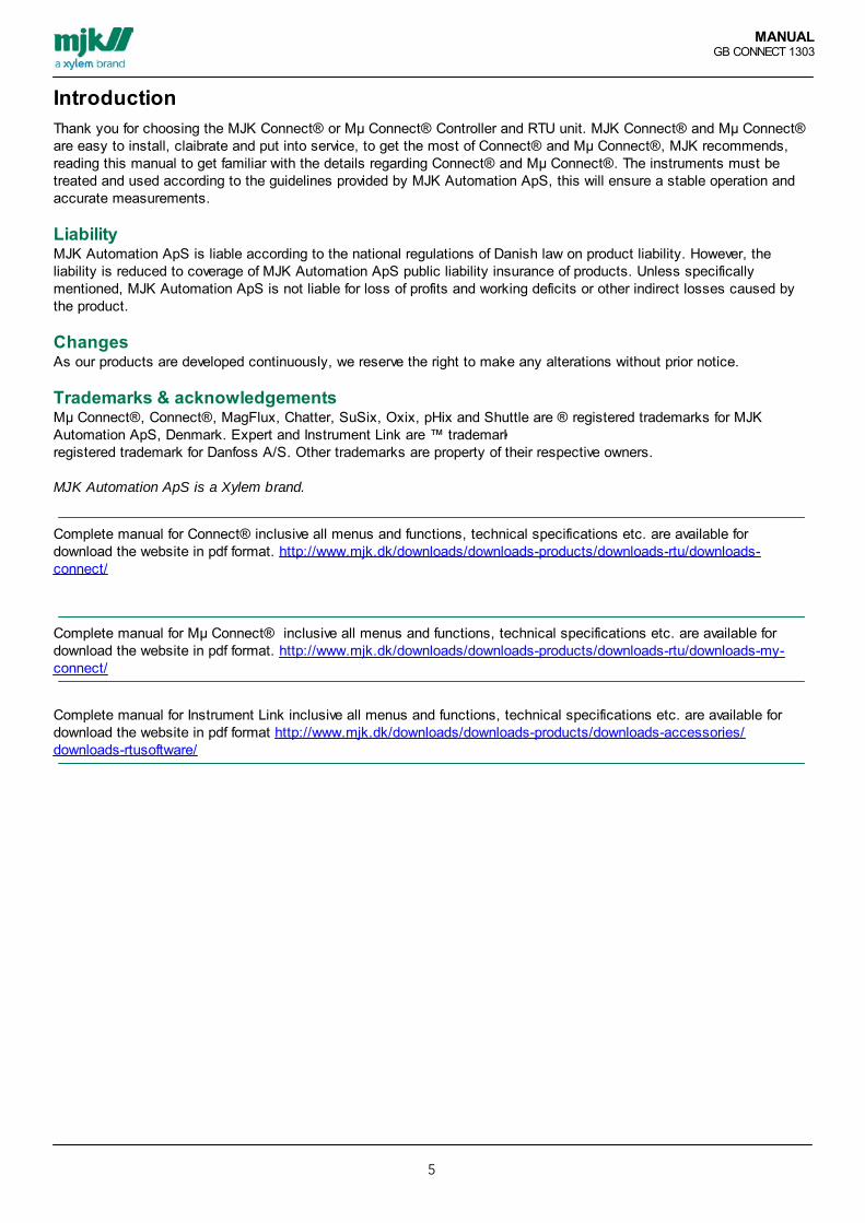
For Mµ Connect® a backup battery of 12VDC, 1,2Ah - 12Ah isrecommended.The backup battery is charged by AC as well as DC supplyabove 14,5 VDC.
The table shows examples of backup battery capacities 2, 7 and 12 Ah.Mµ Connect® Battery capacity@ 12VDC ved 500mA load
70% possible Backup time
2Ah 1,4Ah 1,4Ah/0,5A = 2,8 hours
7Ah 4,9Ah 4,9Ah/0,5A = 9,8 hours
12Ah 8,4Ah 8,4Ah/0,5A = 16,8 hours
Display connected, powersupply = 750mA
For Connect® a backup battery of12VDC, 2-30Ah is recommended."A"
The backup battery willautomatically be charged when theunit is connected to a AC supply"B".
The table shows examples of backup battery capacities 2, 7 and 12 Ah.Connect® Battery capacity@ 12VDC ved 750mA load
70% possible Backup time
2Ah 1,4Ah 1,4Ah/0,75A= 1,87 hours
7Ah 4,9Ah 4,9Ah/0,75A= 6,53 hours
12Ah 8,4Ah 8,4Ah/0,75A= 11,2 hours
MANUALGB CONNECT 1303
21
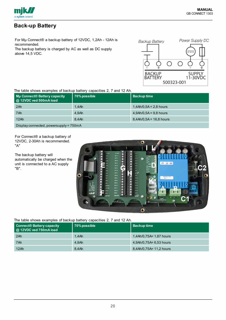
I/O Signals Input-OutputMµ Connect® RTU provides a variety of analog inputs and 2 digital output, making it suitable for most small sizedinstallations.
I/O Amount Voltage
Digital Input (DI) 6 10-30 VDC Passive
Digital Output (DO) 2 20 VAC/28VDC/300 mA Electronic potential free relay
Analogue Input 3 4-20 mA +/- 0,25% of FS Galvanically separated
Mµ Connect connection examples

MANUALGB CONNECT 1303
22
Digital Input (DI)Connecting digital inputMµ Connect® RTU provides 6digital, passive input terminals,activated by a voltage higher than10 VDC and de-activated butvoltage lower than 5 VDC.
Connect® isequipped with 16digital, passive inputswhich can beactivated by a voltagehigher than 10 VDCand deactivated by avoltage lower than 5VDC
The digital inputs ismarked with "H",here shown with I/Omodule 16-8-6-1installed.
Connect® Digital Input
Terminal Name/function
DI 1 10 - 30 VDC
DI 2 10 - 30 VDC
DI 3 10 - 30 VDC
DI 4 10 - 30 VDC
DI 5 10 - 30 VDC
DI 6 10 - 30 VDC
DI 7 10 - 30 VDC
DI 8 10 - 30 VDC
COM DI 1-8 Common ÷ Terminal for DI 1 to DI 8
DI 9 10 - 30 VDC
DI 10 10 - 30 VDC
DI 11 10 - 30 VDC
DI 12 10 - 30 VDC
DI 13 10 - 30 VDC
DI 14 10 - 30 VDC
DI 15 10 - 30 VDC
DI 16 10 - 30 VDC

MANUALGB CONNECT 1303
23
COM DI 9-16 Common ÷ terminal for DI 9 to DI 16The digital inputs (DI 1 - DI 16) can for example be programmed for operation or alarm signals.

MANUALGB CONNECT 1303
24
Connection examples.
The example shows connection of a NC and NOContact for DI1 and DI2 (Note the commonminusterminal with a jumper between ”GND EXT”and ”(-) COM DI 1-8”).
Connecting the NO contact:1. Connect terminal ”15V EXT” to: NO terminal”1”2. Connect terminal ”DI 1” to: NO terminal ”2”3. Connect terminal ”GND EXT” and ”(-) COM DI1-8”.
Connecting the NC contact:1. Connect terminal ”15V EXT” to: NC terminal”1”2. Connect terminal ”DI 2” to: NC terminal ”2”3. Connect terminals ”GND EXT” and ”(-) COMDI 1-8”.
The digital inputs are passive, which causes thevoltage to be supplied from an external voltagesource or from terminal “15V EXT".
Important!A commonly occurring installation error is inputs not connected to the correct, common minus terminal !
Note that inputs share minus in groups of 8 inputs, and that inputs can be individually configured to benormally open (NO) or normally closed (NC).

MANUALGB CONNECT 1303
25
Digital Output (DO)Connection for digital outputsThe outputs can individually be configured to be either NO (Normally Open) or NC (Normally Closed).Mµ Connect® RTU is equippedwith 2 digital outputs (DO1 -DO2), these are electronicpotential free relays.
Connect® is equipped with 8digital outputs (DO1 - DO8) withelectronic potential-free relays (seeposition “G” with an MJK I/OModule 16-8-6-1 installed).
Digital outputs
Terminal Name/function
15V EXT +15 VDC (pull-up for passive signals)
DO 1+ Max. 48 VAC/VDC / 120 mA
DO 1- Ground
DO 2+ Max. 48 VAC/VDC / 120 mA
DO 2- Ground
DO 3+ Max. 48 VAC/VDC / 120 mA
DO 3- Ground
DO 4+ Max. 48 VAC/VDC / 120 mA
DO 4- Ground
DO 5+ Max. 48 VAC/VDC / 120 mA
DO 5- Ground
DO 6+ Max. 48 VAC/VDC / 120 mA
DO 6- Ground
DO 7+ Max. 48 VAC/VDC / 120 mA
DO 7- Ground

MANUALGB CONNECT 1303
26
DO 8+ Max. 48 VAC/VDC / 120 mA
DO 8- Ground
GND EXT Ground for 15V EXTThe digital outputs (DO 1 - DO 8) can for example be programmed for pump operation.

MANUALGB CONNECT 1303
27
Connection example.
The example shows connection of an externaltransfer relay (max. 120 mA), internally orexternally voltage supplied.
Connecting of external transfer relay -internal voltage supply:1. Connect terminal ”15V EXT” to: transfer relaycoil terminal ”+”2. Connect terminal ”DO 1+” to: transfer relaycoil terminal ”-”3. Connect terminals ”DO 1-” and ”GND EXT”.
Connecting of external transfer relay -external voltage supply:1. Connect terminal ”DO 2+” to: voltage supplyterminal ”l” (24 VAC terminal, plus, live)2. Connect terminal ”DO 2-” to: relay terminal ”+”.3. Connect relay terminal ”-” to 24 VAC (n).'
The digital outputs are equipped with electronicpotential relays that canbe loaded with max. 48 VAC / DC / 120 mAresistive load.
Outputs can be individually configured to benormally open (NO, NormallyOpen) or normally closed (NC, Normally Closed).

MANUALGB CONNECT 1303
28
Analogue Input (AI)Connecting for analogue input
Position ”E” on the image, with a I/O module 16-8-6-1 installed.
Analoge Indgange
Terminal Name/Function
15V EXT +15 VDC (pull-up for passive signaler)
AI 1+ 4 - 20 mA, +15 VDC
AI 1- Ground
AI 2+ 4 - 20 mA, +15 VDC
AI 2- Ground
AI 3+ 4 - 20 mA, +15 VDC
AI 3- Ground
AI 4+ 4 - 20 mA, +15 VDC
AI 4- Ground
AI 5+ 4 - 20 mA, +15 VDC
AI 5- Ground
AI 6+ 4 - 20 mA, +15 VDC
AI 6- Ground
GND AI Ground for 15V EXT

MANUALGB CONNECT 1303
29

MANUALGB CONNECT 1303
30
Connection Example.
There is one device in the example on theprevious page (here: Shuttle) with an activeoutput connected to an analog input 1 (AI1) andone pressure transmitter (here: Expert) with apassive output connected to the analog input 2(AI2).
”Passive” connection:1. Connect terminal ”15V AI” to: Expert cable”1” (red cable, +)2. Connect terminal ”AI2+” to: Expert cable”2” (brown conductor, return)3. Connect terminal ”AI2-” to: Connect terminal”GND AI”
”Active” connection:1. Connect terminal ”AI1+” to: Shuttle terminal”11”2. Connect terminal ”AI1-” to: Shuttle terminal”10”
The analogue inputs are passive and galvanicseparated. This means thatvoltage must be supplied from an externalvoltage source or from theterminal marked “15V AI”.
Note that the terminals “AI2” and “GND AI” mustbe interconnected, andthat the inputs only can be configured for 4-20mA.The black cable of the Expert cable set is ashield which must only be connected in case ofsevere noise problems.
Important!Galvanic separation of analog inputs is important! Therefore apply separate power supplies for passive,analog input signals. Otherwise the electrical circuit would not be separated due to the common supply.The inputs each have their own plus and minus terminals. Many installation errors occur, when an input isnot connected to the correct minus terminal

MANUALGB CONNECT 1303
31
Analogue Output (AO) Connecting to an active or passive analogue output
Connecting to active, analogue outputThe analogue, passive output mustreceive no higher than 600Ù.
See position ”F” on the imagewhich includes an I/O module 16-8-6-1
Analogue Output
Terminal Name/Function
15V AO +15 VDC (pull-up for passive signals)
AO 1+ +4 - 20 mA, +15 VDC
AO 1- GND for AO1+
GND AO GND for 15 V AO
The analogue output can be programmed to indicate primary units.

MANUALGB CONNECT 1303
32
Connection Example.The example shows the connection of anexternal control unit, aPLC or similar with an active, analogue input.
”Active” connection:1. Connect terminal ”AO1+” to: PLC terminal”+24 VDC”2. Connect terminal ”AO1-” to: PLC terminal”+mA”3. Connect PLC terminal to ”GND”.
The analogue output (AO1) is passive. For anactive output, the internal voltagesupply from terminal “15V AO” must be used.
The analogue output can only be configured for4-20 mA, and the maximumload of the analogue output is 600Ù.
Connecting to Passive, analogue outputThe example above shows the connection of anexternal control unit, aPLC, or similar with a passive, analog input.
”Passive” connection:1. Connect terminal ”AO1-” to: PLC terminal”+mA”2. Connect terminal ”GND AO” to: PLC terminal”GND”3. Connect terminals ”15V AO” and ”AO1+”.
The analog output (AO1) is passive. For anactive output, the internal voltagesupply from terminals “AO 15V and GND AO”must be used.
Note the jumper between “15V AO” and “AO1 +”,and that the analog output onlycan be configured for 4-20 mA. Max. load of theanalogue output is 600Ù.

MANUALGB CONNECT 1303
33
RS485 CNET & INETConnect® and Mµ Connect® are equipped with serial ports (RS-485) Connect Net(CNET) and Instrument Net (INET), theprotocol is Modbus.The serial communication is used for connection to various MJK Units or Modbus compatible equipment such as e.g.frequency transformers.
CNET is short for CONNECT-NET, and is used to connect to the MJK Display unit or e.g. a WIFI-module (foundinternally in Mµ Connect®).
INET is short for INSTRUMENT-NET and is used when Connect® / Mµ Connect® needs to retrieve data from externalModbus equipment such as flow meters, VFD’s and pressure transmitters.
The Diagram shows the terminals on Mµ Connect.
The Diagram shows the terminalson Connect "D"
Connect® / Mµ Connect®Connect Net (CNET) RS-485 Terminal
Name/Function Cable for Display unit
GND Ground for Connect Net Black
A Data A White
B Data B Grey
15V +15 VDC Red
Connect® / Mµ Connect®Instrument Net (INET) RS-485 Terminal
Name/Function MJK instrument Terminal
GND Ground for Instrument Net -
A Data A A
B Data B B
MANUALGB CONNECT 1303
34
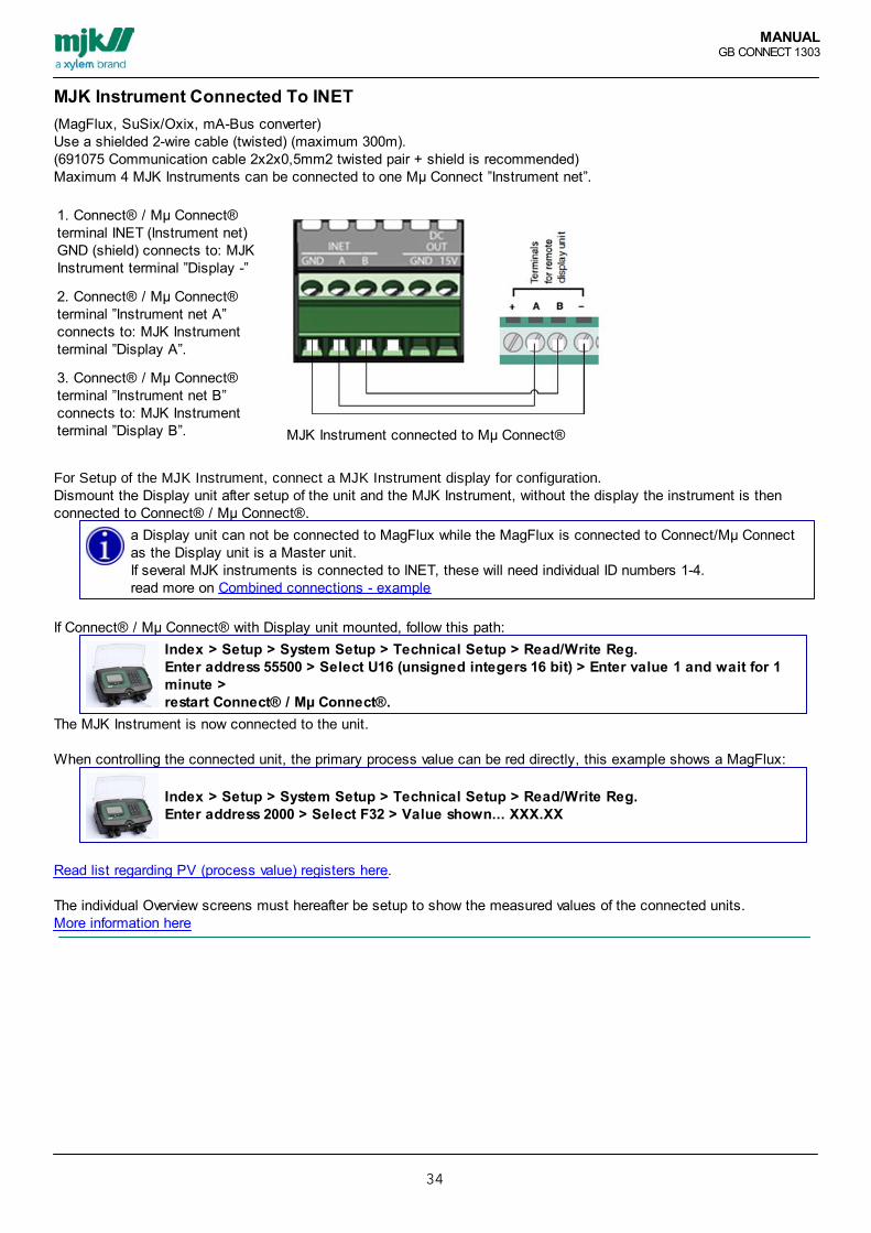
MJK Instrument Connected To INET(MagFlux, SuSix/Oxix, mA-Bus converter)Use a shielded 2-wire cable (twisted) (maximum 300m).(691075 Communication cable 2x2x0,5mm2 twisted pair + shield is recommended)Maximum 4 MJK Instruments can be connected to one Mµ Connect ”Instrument net”.
1. Connect® / Mµ Connect®terminal INET (Instrument net)GND (shield) connects to: MJKInstrument terminal ”Display -”
2. Connect® / Mµ Connect®terminal ”Instrument net A”connects to: MJK Instrumentterminal ”Display A”.
3. Connect® / Mµ Connect®terminal ”Instrument net B”connects to: MJK Instrumentterminal ”Display B”. MJK Instrument connected to Mµ Connect®
For Setup of the MJK Instrument, connect a MJK Instrument display for configuration. Dismount the Display unit after setup of the unit and the MJK Instrument, without the display the instrument is thenconnected to Connect® / Mµ Connect®.
a Display unit can not be connected to MagFlux while the MagFlux is connected to Connect/Mµ Connectas the Display unit is a Master unit.If several MJK instruments is connected to INET, these will need individual ID numbers 1-4. read more on Combined connections - example
If Connect® / Mµ Connect® with Display unit mounted, follow this path:Index > Setup > System Setup > Technical Setup > Read/Write Reg.Enter address 55500 > Select U16 (unsigned integers 16 bit) > Enter value 1 and wait for 1minute > restart Connect® / Mµ Connect®.
The MJK Instrument is now connected to the unit.
When controlling the connected unit, the primary process value can be red directly, this example shows a MagFlux:
Index > Setup > System Setup > Technical Setup > Read/Write Reg.Enter address 2000 > Select F32 > Value shown... XXX.XX
Read list regarding PV (process value) registers here.
The individual Overview screens must hereafter be setup to show the measured values of the connected units. More information here

MANUALGB CONNECT 1303
35
Combined Connection - example
When one Connect, one SuSixand one MagFlux enhed isconnected in network, ”Instrumentnet” on Connect unit is conectedto ”Terminals for remote displayunit” on SuSix and for ”Terminalsfor remote display unit on MagFluxas illustrated.
1. Connect terminal ”Instrumentnet GND” (shield) to: SuSixterminal ”Display -” and MagFluxterminal ”Display -”.
2. Connect terminal ”Instrumentnet A” to : SuSix terminal”Display A” and MagFlux terminal”Display A”.
3. Connect terminal ”Instrumentnet B” terminal: SuSix terminal”Display B” and MagFlux terminal”Display B”.
4. Connect unit must beconfigured with an unique IDnumber, so does SuSix andMagFlux .
A 2-wire cable with shield(maximum 300m ) must be used.No more than 4 SuSix and/orMagFlux units can be connectedto one Connect units ”Instrumentnet”.
Ordernumbers for this configuration
20534x Connect base, with Display, incl. I/O module, with modem communications module by choice
2063xx SuSix converter with or without Display
2079xx MagFlux converter with or without Display

MANUALGB CONNECT 1303
36
Danfoss VLT FC202 Connection To INETMµ Connect - Danfoss VLT FC202:
I NET (Instrument NET):Terminal A on INET on MµConnect for terminal 68 onDanfoss VLTTerminal B on INET on MµConnect for terminal 69 onDanfoss VLT shield for GND.
Danfoss VLT FC202:jumper between the following terminals:
from terminal 13 to terminal 27from terminal 18 to terminal 29
Danfoss VLT FC202 setupParameter Option Danfoss VLT, description
8-30 2 (MODBUS) Danfoss VLT / Main menu / Parameter 8 / 8-3x FC port settings / 8-30 =[2] MODBUS RTU
8-31 ID nr. Pumpe 1 VLT =100,Pumpe 2 = 101
Danfoss VLT / Main menu / Parameter 8 / 8-3x FC port settings / 8-31Pump 1 [100], pump 2 [101]
8-32 BAUD rate = 2 (9600 baud) Danfoss VLT / Main menu / Parameter 8 / 8-3x FC port settings / 8-32= [2] 9600 baud
8-33 Parity = 0, (equal parity) Danfoss VLT / Main menu / Parameter 8 / 8-3x FC port settings / 8-33 =[0] equal parity
Control signalParameter Option Danfoss VLT, description
5-02 (klemme 29 condition) = 1(output)
Danfoss VLT / Main menu / Parameter 5 / 5-0x FC port settings / 5-02 =[1] Output

MANUALGB CONNECT 1303
37
Schneider Altivar 61/71 Connected To INETMµ Connect - Schneider Altivar 61/71
I NET (Instrument NET):Terminal A on 'INET in MµConnect for Terminal B at instrument net inMµ Connect Shield for GND.
Schneider Altivar 61/71 Setup.Communication parameters
Menu item Select Description
1. Drive menu OK
1.9Communication
MODBUS NETWORK
MODBUS ADDRESS Set Modbus id-nr to the needed value ( 100 – 107) to finish, pressOK. Pump 1, ID nr. =100, Pump 2 = 101
MODBUSBaudrate
9.6 Kbps (9600 baud) Set baud rate for 9.6 Kbps- OK
MODBUSFormat
8-E-1 Set format 8-E-1 – OK
Modbus Timeout 10.0 s Set value 10.0 s – OK. Restart the Device to implement thechange.
Control signalMenu item Select Description
1. Drive menu OK
1.6 Command OK
Ref.1 channel OK
MODBUS OK
Profile OK
Cmd Channel 1 OK, select ”I/O profile” – OK
Cmd Channel 1 Select ”TERMINALS” – OK Pres ESC
Error signalMenu item Select Description
1. Drive menu OK
1.8 FAULTMANAGEMENT
OK,
AUTOMATICRESTART
Select ”Yes” – OK Press ESC and select
COM. FAULTMANAGEMENT
Modbus Faultmgt
Select ”ignore”-OK Tryk 4 * ESC to return to main screen
MANUALGB CONNECT 1303
38
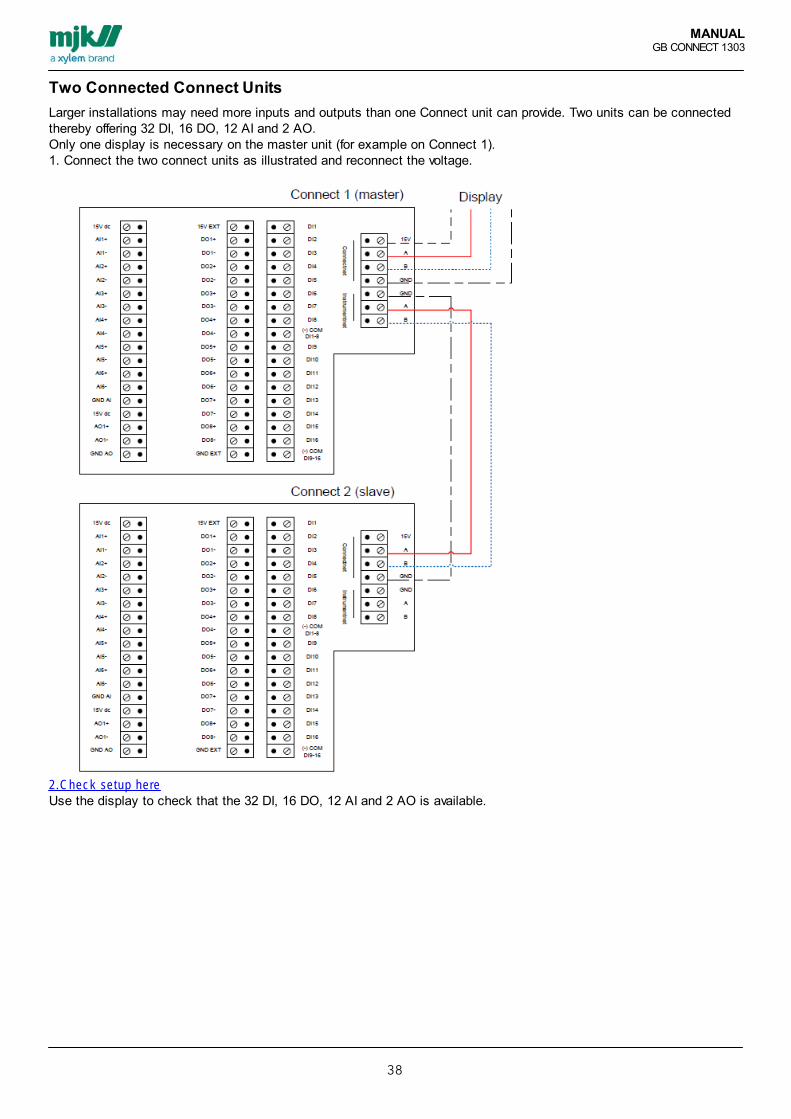
Two Connected Connect UnitsLarger installations may need more inputs and outputs than one Connect unit can provide. Two units can be connectedthereby offering 32 DI, 16 DO, 12 AI and 2 AO. Only one display is necessary on the master unit (for example on Connect 1).1. Connect the two connect units as illustrated and reconnect the voltage.
2.Check setup hereUse the display to check that the 32 DI, 16 DO, 12 AI and 2 AO is available.

MANUALGB CONNECT 1303
39
CONNECT Display UnitConnecting the Display.Disconnect the power supply for Mµ Connect.Connect cables from the MJK Display unit to CNET terminal as illustrated; ensure the connection is establishedcorrectly.Restart the power supply for Mµ Connect®, so that the Display unit is is now powered via the terminal.
Remove the 4 screw securing thefront cover, mount the plug fromMJK Display unit in the femalesocket marked with the text"DISPLAY". The plug can only bemounted "properly", the release-pinmust face the mini-USB.
See position ”L” on the imagewhich includes an I/O module 16-8-6-1
Order numbers for this configuration:205505 Connect® Display Unit
205508 Kit for mounting of Connect display at panel front
205509 MµConnect® Display mounting kit for 205505

MANUALGB CONNECT 1303
40
WiFi And DisplayIf WiFi and Display is to be used at the same time, connect the display to ID 2 and the amount of Displays for 2.
Change Display ID number for ID 2 and the amount of Displays for 2.
On Connect® / Mµ Connect® with Display mounted follow this path:
Index > Setup > Network Setup > Connect network > Change Display ID No. > 2 > OKNumber of Displays > 2 > OK

MANUALGB CONNECT 1303
41
USBAttach the mini-USB cable to the mini-USB socket on the front of Mµ Connect. As soon as the connection isestablished the Mµ Connect can be configured using Instrument Link installed on a laptop PC.The connection is established when the disc-drive named ”MYCONNECT” is visible i ”My Computer” additional ”MJKConnect” units cannot be connected to Instrument Link similarly.
To avoid communication gaps between the Laptop PC and Mµ Connect it is recommended to finish all configuration, andshutting down Instrument Link before disconnecting the USB.
USB on Connect UnitAttach the mini-USB cable in themini-USB socket marked with "I"on the image. As soon as theconnection is established theConnect unit can be configureredusing Instrument Link installed ona laptop PC.
The connection is establishedwhen the disc-drive named”CONNECT” is visible i ”MyComputer” additional ”MJKConnect” units cannot beconnected to Instrument Linksimilarly.
To avoid communication gapsbetween the Laptop PC and MµConnect it is recommended tofinish all configuration, andshutting down Instrument Linkbefore disconnecting the USB.

MANUALGB CONNECT 1303
42
GSM/GPRS modemMounting and connecting GSM/GPRS modem on ConnectAn antenna needs to be mounted for theConnect unit to be able to deliversurveillance and alarm data using thetelephone and or data grid.
This example shows mounting andconnecting a Connect GSM/GPRSmodem, as well as connection of MJKGSM or GPRS antenna: 205116/18 or205120
Mounting and connecting
1. Remove the front panel Connect(release the 4 screws).
2. Remove the Connect I/O module(release the4 screws).
3. Mount the GSM/GPRS modem (incl.SIM-card) in the internal S4 interface forcommunication unit and tighten thescrews delivered with the modem(4 pcs.M3x6).
4. Connect the GSM/GPRS modem "K"to the needed antenna using the cableMMCX male-plug. The antenna isautomatically active.
5. Reinstall Connect I/O module.
6. Reinstall Connect front panel.
Note: Please ensure that the plugs on theI/O module is mounted correct in themainboard, before locking the moduleusing the 4 screws. Mounted incorrectlycan cause the entire unit to not restart orthat some functions will be out of order.
Connect order numbers for this configuration
205343 Connect® base w/ display GSM/GPRS I/Omodule 16-8-6-1
I/O modul 16-8-6-1
OR
205321 Connect® base w/ display I/O modul 16-8-6-1 I/O modul 16-8-6-1
and
205543 GSM/GPRS modem Quad band module

MANUALGB CONNECT 1303
43
SIM-card Mounting For optimal usage of Mµ Connect’s surveillance and alarm options a phone or data SIM-card must be mounted.
The communication is configured using Instrument Link.
Connection via the SIM card(the GSM/GPRS signal) issecured using an externalantenna (not included).
To mount the SIM-card in aConnect unit
1. Remove the Connect front panel(display unit, 4 screws).
2. Dismount the Connect I/Omodule (4 screws).
3. Mount the GSM module in theinternal S4 interface forcommunication units and lockusing the supplied screws (4pcs. M3x6).
4. Pull back the lockingmechanism and tilt it upwardsinsert the SIM-card in thelocking mechanism, it shouldenter easily
5. Push the locking mechanismdown and push forward to lockit.
6. Reninstall the Connect frontpanel.

MANUALGB CONNECT 1303
44
Connecting Antenna
Mµ Connect needs an antenna todeliver surveillance and alarm datausing the phone or data network.
Mount the antenna on top of theMµ Connect unit.
The antenna should be mountedexternally on steel panels. Theantenna does not need furtherconfiguration, but will instantlyimprove the GSM/GPRS signal,depending on the mounting andshielding conditions.
Read Datasheet GB 6.26 GSM-GPRS Antennas Datasheet fordetails.
There are several different antennas for the GSM/GPRS signal. Antennas are delivered with or without signalamplification. See the specification datasheet and ask a technician if necessary to ensure the best antenna solution foryour setup.

MANUALGB CONNECT 1303
45
PSTN modemMounting and connecting a PSTN modem in ConnectMounting and Connecting
1. Remove the Connect front panel(display unit, 4 screws).
2. Remove Connect I/O module (4screws).
3. Mount the PSTN modem in theinternal S4 interface forcommunication units and attachit with the supplied screws (4pcs. M3x6).
4. Connect the PSTN modem withthe supplied RJ11 cable. If themodem is to be connected to aterminal, the cable must bestripped at one end, and the redand blue conductor connectedto the terminal block. Do notconnect the black and yellowconductors.
5. Reinstall the Connect I/Omodule..
6. Remount the front panel.
OBS: Ensure that the connectorsof the I/O module aremounted correctly to themotherboard, before the module issecured with 4 screws. Incorrectinstallation may cause that theConnect unit fails to start or thatcertain functions do not executeproperly.
Connect order numbers for this configuration
205341 Connect® base w/ display PSTN I/O module 16-8-6-1 I/O module 16-8-6-1
OR
205321 Connect® base w/ display I/O module 16-8-6-1 I/O module 16-8-6-1
And
205541 PSTN modem module

MANUALGB CONNECT 1303
46
RS 232 Communications Module
RS-232 module is placed inposition ”K” on the image. On theimage it is however a GSMmodem that are installed.
1. Remove Connect front panel(display unit, 4 screws).
2. Remove Connect I/O module (4scews).
3. Mount RS-232 module in theinternal S4 interface forcommunication units and attchusing the supplied screws (4pcs. M3x6).
4. Reinstall Connect I/O module.5. Reinstall Connect front panel.

MANUALGB CONNECT 1303
47
RS 232 - Datatransmitter 795Example showing mounting and connecting MJK 795 Data Transmitter to RS-232 com-module.Mounting and connecting
1. Stop all running processes.2. Remove Display or blind lid3. Disconnect power supply4. Connect RS-232 module for MJK 795
Data Transmitter using a 2-wire-shielded cable:
Connect terminal ”TxD” to 795 terminal”RS232/A”Connect terminal ”RxD” to 795 terminal”RS232/B”Connect terminal ”GND” to 795 terminal”RS232/GND”
5. Reinstall Connect front panel.6. Restart power supply
Note: Ensure that the connectors of the I/O module aremounted correctly to the motherboard,before the module is secured with 4screws. Incorrect installation may causethat the Connect unit fails to start or thatcertain functions do not execute properly.
the shown example is Datatransmitter 795Master/Gateway for RS-232 module.
Connect order numbers for this configurationdenne konfiguration
205321 Connect® base w/ display I/O modul 16-8-6-1 I/O modul 16-8-6-1
205544 RS 232 galvanic insulated module

MANUALGB CONNECT 1303
48
RS 232 - Dataradio TP 6000Example shows mounting and connecting of Dataradio TP 6000 for RS-232 com-modul.Mounting and Connecting
1. Remove Connect front panel (displayunit, 4 screws).
2. Stop power supply3. Remove Connect I/O module (4
screws).4. Mount RS-232 module in the internal S4
interface for communication units andattach using the supplied (4 pcs.M3x6). if it is not already mounted.
5. Connect RS-232 module to the dataradio using MJK 3-conductor DB25-cable:
Connect terminal ”TxD” to DB25-wire bluewireConnect terminal ”RxD” to DB25-wirebrown wireConnect terminal ”GND” to DB25-wireblack wire6. Reinstall Connect I/O module.7. Connect the external battery negative-
terminal for ”-12 VDC Accumulator” andthe positive terminal for ”+12 VDCAccumulator”.
8. Geninstallér Connect frontpanelet.9. Connect the extrenal battery negative
terminal to the MJK 2-conductor DB9-cables black conductor, and thepositive terminal to the DB9-cables redconductor.
10. Connect the DB9-plug and the antennato the data radio.
Note: Ensure that the connectors of the I/O module aremounted correctly to the motherboard,before the module is secured with 4screws. Incorrect installation may causethat the Connect unit fails to start or thatcertain functions do not execute properly.
Connect order numbers for this configuration
205321 Connect® base w/ display I/O modul 16-8-6-1 I/O modul 16-8-6-1
205544 RS 232 galvanic insulated module
550242 Accumulator 12V/12Ah

MANUALGB CONNECT 1303
49
RS 485 Communications Module
An external antenna need to bemounted for Connect to becapable to deliver surveillance andalarm data using the phone or datanetwork.
Mounting and connecting
Remove the Connect front panel(display unit, 4 screws).
1. Disconnect power supply
2. Remove the Connect I/Omodule (4 screws).
3. Mount the RS 485 module onthe internal S4 interface forcommunications units onposition "K" and attach usingthe supplied screws (4 pcs.M3x6). (on the illustrationalimage a GSM module ismounted, see detail-image forthe design of the RS-485module)
4. Reinstall Connect I/O module.
5. Reinstall Connect front panel.
Note: Ensure that the connectorsof the I/O module are mountedcorrectly to the motherboard,before the module is secured with4 screws. Incorrect installationmay cause that the Connect unitfails to start or that certainfunctions do not execute properly.

MANUALGB CONNECT 1303
50
WIFI ModuleSee WiFi and Display

MANUALGB CONNECT 1303
51
Connecting Ethernet TCP/IP To communicate using the Ethernet, an external ethernet module such as Moxa Nport is connected to Connect® / MµConnect®.Electrical connection
Port pin 9 Pin D-Sub Female
1 GND
3 B
4 A
Serial Moxa Nport setup:
Baud Rate: 9600 Parity: Even
Data Bits: 8 Stop Bits: 1
Flow control: None FIFO: Deactivated
Interface: RS-485 2 kabel For detailed setup read: GB Applications note RS 485 to TCP IP using Moxa Nport unit.

MANUALGB CONNECT 1303
52
Front Panel Cut-out TemplateConnect® Front panel template.the outer lines illustrates Connect® cabinet, the grey area indicates the hole that are to be cut out of the board.
The shown template is not in 1:1. It merely illustrates how a 1:1 ratio template can be made on for example a size A3piece of paper.

MANUALGB CONNECT 1303
53
Daily UsageThis is a quick guide to get started using the Connect.The following examples in this chapter will show and explain how a Connect unit is configured for pump control of 2pumps on a waste water pump station.In Connect, use the function "Pump Control 1" which controls the pumps based on the level in the pump sump.
The complete manual for Connect® and Mµ Connect® is always available on www.mjk.dk
This guide covers Connect® in the following firmware versions:Firmware versionsProduct Number Revision
Connect® Base unit 844003 007-017
Connect® Display 841021 003

MANUALGB CONNECT 1303
54
LED signalsLED Light on the front of Mµ Connect is used for generalcommunication, this way a laptop computer is not necessary ifthe Mµ Connect is already configured.
The individual LEDs will blink/light up in different frequenciesthereby indicating which process is active in the the Mµ Connectunit e.g. Communication or warnings.
Power up:All LEDS are lit followed by runninglight oncedown and once up.
Status:Mµ Connect® control unit is ready.
Communication:Modem is resetting, or the signalfor the GSM modem is too low.(Modem is reset once per hour)
Modem is reset and Mµ Connect®is ready to receive incomingsignals.
The unit is being called and awaitscommunication.
The unit is connected and data canbe transferred via modem andWiFi.
ALARM:There is an active alarm signal
All LEDS are turned on shortly when the USB isconnected and in a 10 minute interval.
A more detailed table overview of the LED signals:LED Signal Description
All LEDS are lit followed by running light once down andonce up.
Power-up sequence, every time the power is restored
STATUS
LED blinks showing an interval of 3 sec. Mµ Connect RTU unit is ready
Communication
LED lit permanently Modem is resetting, or the signal for the GSM modem istoo low.(Modem is reset once per hour)
LED blinks showing an interval of 3 sec. Modem is reset and Mµ Connect® is ready to receiveincoming signals.
LED blinks showing an interval of 1 sec. The unit is being called and awaits communication
LED blinks showing an interval of ½ sec. The unit is connected and data can be transferred viamodem and WiFi
Alarm
LED blinks showing an interval of ½ sec. There is an active alarm signal.
All LEDS are activated briefly with a 10 minute interval when the USB is connected

MANUALGB CONNECT 1303
55
Display ScreenThe Connect® Display unit can work no as well Connect® as MµConnect®.For daily usage, use the 4 soft keys beneath the display tonavigate the menus.
Display KeysNumeric keys and soft keys (soft keys: the function is determined by the installed display firmware) are used for start-upand normal operation of the Connect unit. The function of the 4 soft keys is shown at the bottom of the display (here:Select and Set up). The numeric keypad on the right is used for direct menu selection and alpha-numeric entry ofnames and texts.
Symbols and actual functions are described in details in the sections regarding the individual menus. The numeric keyscan be used as short-cuts through the menu system and/or alfa-numeric programming of names, values and texts.
Key Function Description
Outer Left Key The outer left key will normally switch between Menu and Index (Toggle function)
Arrow keys The center-arrow keys is used to browse up/down in the menus.
Outer Right Key the Outer Right Key is mostly used for confirmation of choice and/or access to the nextmenu item
Contrast SettingAdjust the contrast setting by pressing the 2 outer display keys(the keys in the red circles) simultaneously then adjustcontrast, using the up/down keys until the desired contrast isachieved.
Save the new contrast setting by pressing the 2 outer displaykeys simultaneously once more.
Reset the SystemIt is possible to reset and refresh all system readings and key combinations by pressing all four buttons simultaneously.This feature is especially useful, when the device is being serviced, and the display language is not understood by theservice personnel. A reset of the system changes the language into English.
Bemærk: A system reset must not be confused with the very comprehensive “Restore factory settings”,which erases all local configurations and preferences, and replaces them with the original factory settings.

MANUALGB CONNECT 1303
56
Function KeysThe daily operation of Connect® and Mµ Connect® is programmed using the functions keys.The function keys (numeric keys) is also used as shortcuts and as fore entering names and texts (alfa-key function).
Each function key predefined functions andcan be adapted depending on individualneeds.
When select Index function, an overview of the defined oversigtsskærme is created.
select the desired screen, by moving the marker up/down using the arrow keys and
pressing OK
Function key 1 - 3 provides the following functions:
Pump Control 1. When arriving to the Connect® unit, the oversigtsskærm will show this screen.
Informations in the screen covers; current level, pump 1 operating condition and start/stop levels.
Pump Control 2. When arriving to the Connect® unit, the oversigtsskærm will show this screen..
Informations in the screen covers; current level, pump 1 operating condition and start/stop levels.
Function key 1 to 3 is only active when "create oversigtsskærm" is selected in the functions menu

MANUALGB CONNECT 1303
57
Function key 4 to 9 provides the following functions:Function key 4. Digital input
Informations in this screen shows the status of all Digital input terminals.
Function key 5. Digital Output
Informations in this screen shows the status of all Digital Output terminals.
Function key 6. Analogue Input
Informations in this screen shows the status of all Analogue Input terminals.
Function key 7.Communication Module Status
Shows status on Communication. Content depends on the communication module.

MANUALGB CONNECT 1303
58
Function key 8. Alarm List
Informations regarding status on all alarms.
Active alarms is illustrated when the box is marked with "X". Choose the line showing the active alarm
and press "OK" for further information regarding start and stop time of finished alarms .
When an alarm is active the dial-up function can be active and the alarm will be called to phone numbers
in the defined in the call-list the installed communications module is automatically detected. The alarm-
list is only available when a PSTN/GSM communications module is installed.
Function key 9. I/O Status
Status on all input and output as well as analogue limits, Virtual analogue input and Logical Functions
(LF).
Scroll down using the arrow keys to see all menu items

MANUALGB CONNECT 1303
59
Basic Configuration; Pump Control 1This part explains how to configure the Connect unit for pumpcontrol of waste water pump station with 2 pumps.I Connect benyttes funktionen ”Pumpestyring 1” som styrerpumperne via niveauet i pumpesumpen.
This illustration shows a pump station with 2 submergedpumps.
Signal list.First step is creating a signal list, thereby creating a complete overview of the signals between pump control of thepumps and from the pumps to the pump control.The following tables shows examples from a standard equipped pump station. The list shows signals to the digital input in this example.
Digital input Signal Name Relay function Delay Alarm/Operation
Alternation
DI 1 Operation P1 NO 0 sec. In use In use
DI 2 Operation P2 NO 5 sec. In use In use
DI 3
DI 4 Thermoalarm P1 NO 15 sec. Alarm
DI 5 Thermoalarm P2 NO 15 sec. Alarm
DI 6
DI 7 Klixon P1 NO 0 sec. Alarm
DI 8 Klixon P2 NO 0 sec. Alarm
DI 9
DI 10 MAN-0-AUT P1 NO Alarm
DI 11 MAN-0-AUT P2 NO Alarm
DI 12
DI 13
DI 14
DI 15
DI 16 High LevelSwitch
NO Alarm

MANUALGB CONNECT 1303
60
The list shows the signals connected to the digital outputs in the example.
Digital Output Signal Name Relay function Closing time(sec. on-time)
Delay
DO 1 Start / stop P1 NO- constant 0 sec. 0 sec.
DO 2 Start / stop P2 NO- constant 0 sec. 0 sec.
DO 3
DO 4
DO 5
DO 6
DO 7
DO 8 Joint reset ofthermo error
NO- timecontrolled
1 sec. 0 sec.
The list shows signals to the analogue input in this example.
Analogue Input Signal Name Scaling 4mA Scaling 20mA Unit Unit Midling
AI 1 Level 0 300 Level cm 0 sec.
AI 2 Power P1 0 10 Other Units A 0 sec.
AI 3 Power P2 0 10 Other Units A 0 sec.
AI 4
AI 5
AI 6
Analogue limits In Use / Not In Use
Signalnavn Setpoint Delay (seconds) Call
AI 1 High In Use High LevelAlarm
XX 5 In Use
AI 1 Low Not In Use AI 1 LA 0 0 Not In Use
AI 2 High In Use High Levelalarm P1
0 0 Not In Use
AI 2 Low Not In Use AI 2 LA 0 0 Not In Use
AI 3 High In Use High Level alarmP2
0 0 Not In Use
AI 3 Low Not In Use AI 3 LA 0 0 Not In Use
AI 4 High Not In Use AI 4 HA 0 0 Not In Use
AI 4 Low Not In Use AI 4 LA 0 0 Not In Use
AI 5 High Not In Use AI 5 HA 0 0 Not In Use
AI 5 Low Not In Use AI 5 LA 0 0 Not In Use
AI 6 High Not In Use AI 6 HA 0 0 Not In Use
AI 6 Low Not In Use AI 6 LA 0 0 Not In Use
ConfigurationNext step is to configure the Connect according to the shown signal list.In Functions menu choose Pump Control 1. configure the individual menu items according to the signal list.
Functions menu > Pump Control 1 contains the following items:Number of pumps: Number of pumps used in the configurationMeasurement: What analogue input is attached to the level measurement incl. scaling and signal namePumps: Configuration of the digital output for the pumps

MANUALGB CONNECT 1303
61
Start-stop Levels: start-stop levels on the selected amount of pumpsControl Word: 16-bit Control Word for intelligent pump control Additional Functions:o Flow Calculationo Set point displacemento Depth pumpingCreate Overview Screen: will create the overview screen 1 as configured with the selected information

MANUALGB CONNECT 1303
62
Step by step:the setup will look approximately like this in the display
Select Functions Menu
Select Pump Control 1
Select In Use
Enter 2 select "OK"Enter 2 and select "OK"

MANUALGB CONNECT 1303
63
Pump OperatingThis section is based on ”Pump Control 1” which is the most commonly used Pump Control function.
Function key 1 will provide access to the Pump Control, and will normally bethe active screen on the Connect unit when working on the station. Please note the pre-defined read-outs that are shown here, can be adaptedtowards the individual needs.The Daily usage of pumpestyring 1 is accessed withfunktionstast 1. oversigtsskærm 1 is standard and created in the function pumpestyring 1.The most important informations in regards to the pump operation, currentLevel, Pump operational state and start/stop levels is shown in this screen.
If Connect® is left in this screen, this is the first screen shown at the next visit on the pump station.
Overview Screen Pump Control 1.
by pressing the outer right button beneath the display, P2, the screen will switch to Pump 2 (control), and the"P2" (on the outer right will change to P3 or P4, depending on how many pumps is entered in the function pumpestyring1.
Choose what line to enter, by using the arrow-keys and press Select.
The actual screen may look differently depending on the individual setup.
Information and overview screen options:Text line Description
Pump Control 1 This is the name of the Function, change this for e.g. the name of the pumpstation in Pump .
Level The actual level of the pump sump
P1 Operation The operating conditions of the Pump is shown with text and icons, see the listbelow
P1 Start Change the Start Level for the pump by marking the line and simply entering thenew value using the numeric keys, then press "OK".
P1 Stop Change the Stop Level for the pump by marking the line and simply entering thenew value using the numeric keys, then press "OK".
Index Switch between Overview screen and Functions Menu.
Select Up/Down arrow is used to scroll the screen and to mark up a line or function.
P2 Ved at taste på højre taste under displayet, P2 skiftes der til et tilsvarende billedefor pumpe 2 og denne tast skifter nu navn til P3 - P4 , afhængigt af hvor mangepumper der er oprettet under funktionen pumpestyring 1.
Operating state of the Pump Icon
Description
P1 Operating Digital output for the pump is operating and the return signal is OK.

MANUALGB CONNECT 1303
64
P1 Stop Digital output the pump is stopped
P1 Failure Digital output for the pump is operating, the return signal is missing
P1 Blocked Digital output for the pump is blocked

MANUALGB CONNECT 1303
65
Start / Stop LevelTo adjust start / Stop level do the following:
Press numeric key "1" to show Overview screen for Pump Control 1.
Use the arrow keys and select the P1Start line
The last digit in the Start level ismarked, now enter the new level usingthe numeric keys.
When the desired value is entered,select "OK" to save the value in theConnect®
Now scroll to the Stop Level line, using the arrow keys.
Use the arrow keys and selectthe P1 Stop line
The last digit in the Stop level is marked,now enter the new level using thenumeric keys.
When the desired value is entered, select"OK" to save the value in the Connect®
To change the start/stop level on the additional pumps, press arrow down from "stop level" P1.P1 in the bottom-right corner will now change to P2 when the outer right display key is pressed. Press the outer right display key again, and the screen switches to Pump 2.Repeat the above described procedure.Press the outer-right display key continuously to switch between the pumps that are configured in Pump Control 1.
It is a prerequisite that Pump Control 1 is set-up and he Create Overview Screen is executed.
If a stop level higher than the start level is selected, the function is changed from emptying to filling.
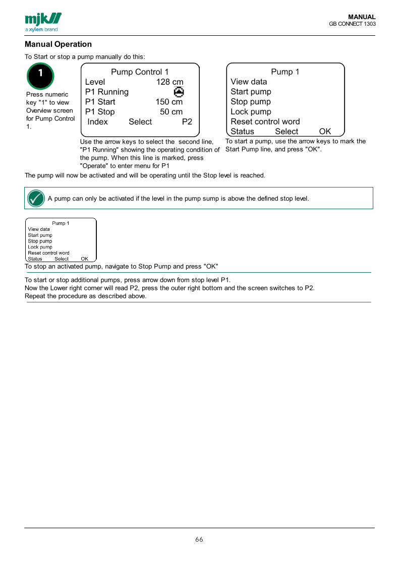
MANUALGB CONNECT 1303
66
Manual OperationTo Start or stop a pump manually do this:
Press numerickey "1" to viewOverview screenfor Pump Control1.
Use the arrow keys to select the second line,"P1 Running" showing the operating condition ofthe pump. When this line is marked, press"Operate" to enter menu for P1
To start a pump, use the arrow keys to mark theStart Pump line, and press "OK".
The pump will now be activated and will be operating until the Stop level is reached.
A pump can only be activated if the level in the pump sump is above the defined stop level.
To stop an activated pump, navigate to Stop Pump and press "OK"
To start or stop additional pumps, press arrow down from stop level P1.Now the Lower right corner will read P2, press the outer right bottom and the screen switches to P2.Repeat the procedure as described above.

MANUALGB CONNECT 1303
67
4 different icon referrinf to the operating conditions of the pump:Pump Operating Condition Ico
nDescription
P1 Running Digital output when the pump is running and the feedback signal is ok.
P1 Stopped Digital output when the pump has stopped and the feedback signal ismissing
P1 Error Digital output when the pump is in use and the feedback signal is missing.
P1 Blocked Digital output for the pump is not in operation/stopped
Switch between the pumps selected for Pump Control 1 by pressing the outer right key "P1".
It is a prerequisite that Pump Control 1 is fully set-up and that Overview Screen is created.
Use arrow key to scroll for eventual more lines.

MANUALGB CONNECT 1303
68
Pump Data
in this menu "View Data" will create overview screen for data fromthe the selected pump.
Der kan vælges imellem 3 forskellige data skærme:
Totals Today
Yesterday
Tekst line Description
Pump 1 This is the name of the function. You can change it to e.g. the pump number or any individualname.
P1 Total/Today/ Yesterday Cnt. Count values (number of starts) for the selected pumps. The counter is connected to theselected DO for the pump. The counter is shown as totals, today values (since midnight)and as yesterday values. See register here
P1 Total/Today/ Yesterday tim. Time values (on-time) for the selected pumps. The counter is connected to the selected DOfor the pump. The counter is shown as totals, today values (since midnight) and asyesterday values.. See register here
P1 Volume/Total/ Today/Yesterday
Volume values (number of units) for the selected pump. The counter is connected to theselected pump.The counter is shown as totals, today values (since midnight) and as yesterday values . Seeregister here
P1 Capacity, Today Capacity shows the total volume for all devices. The counters is shown as totals, todayvalues, since midnight values and yesterday values. See register here
Status Back to Main screen regarding pumpestyring1.
Select Up/down arrows are used to scroll up and down in the current screen and select a line orfunction.
Next Change to next pump data screen.
It is a prerequisite that Pump Control 1 is set-up an that Overview Screen is createdt.

MANUALGB CONNECT 1303
69
Reset Control Word
Creating Overview Screen prerequisites that Pump Control 1 is set-up.

MANUALGB CONNECT 1303
70
Menus and OperationThis chapter describes the simple menus and operating functions for Mµ Connect®.Mµ Connect® is controlled using a MJK Display Unit, or Instrument Link which makes configuration and operation evenmore simple and easy.The functions of Mµ Connect can be divided in 5 main areas, each providing the necessary configuration and functions.These menus and function options provides the opportunity of configuring various parameters such as pump control,signal definitions, general configuration and alarms. Besides this, the service menu will provide additional options. The five main areas are:• Function menus
• Signals (I/O)
• Alarm Signals
• System and Network setup
A Graphic view of the menu system is shown,below. The menu system illustrates when a MJK Display Unit isconnected to the Mµ Connect.
Similar menu items are seen in the Instrument Link menus.In Instrument Link, the system and network menus are merged into one menu.An overview of the menus and functions in Connect® and Mµ Connect® is here shown from Instrument Link.

MANUALGB CONNECT 1303
71
1. Functions menu 2. Signals (I/O) 4. System Setup
1. Functions menu 1.1 Pump Control 1 1.1.1 Number of pumps 1.1.2 Measurement 1.1.3 Pumps Setup 1.1.4 Start/Stop level 1.1.5 Control Word 1.1.6 Additional Functions 1.1.7 Create Overview Screen 1.2 Pump Control 2 1.2.1 Number of pumps 1.2.2 Measurement 1.3.3 Pumps Setup 1.4.4 Start/Stop level 1.5.5 Control Word 1.6.6 Additional Functions 1.7.7 Create Overview Screen 1.3 Optm. Pump Control 3 1.3.1 Number of pumps 1.3.2 Measurement 1.3.3 Pumps Setup 1.3.4 Frequency Converter Type 1.3.5 Flow Input 1.3.6 Level Parameters 1.3.7 Functions Setup 1.3.8 Adaptive Optimizing 1.3.9 Control Word 1.3.10 Additional Functions 1.3.11 Create Overview Screen 1.4 Optm. Raw Water Control 1.4.1 Pumps 1.4.2 Frequency Converter Type 1.4.3 Flow Input 1.4.4 Frequency States 1.4.5 Functions Setup 1.4.6 Adaptive Optimizing 1.4.7 Additional Functions 1.4.8 Create Overview Screen 1.5 Interlock 1.5.1 Receiver 1.5.2 Transmitter 1.6 Storm Flow Calculation 1.7 Logical Function 1.8 Data Logger 1.8.1 Standard Data Logger 1.8.2 Extended Data Logger 1.8.3 Event Data Logger 1.8.4 Display Data Logger
2.1 Digital Inputs 2.2 Digital Outputs 2.3 Analog Inputs 2.4 Analog Outputs 2.4.1 AO 1 2.5 Virtuel Analog inputs
4.1 Status 4.2 Overview Screen Setup 4.3 Language 4.4 Set Time/Date 4.4.1 Set Time/Date 4.4.2 Time Format 4.4.3 Daylight saving 4.5 Communication 4.5.1 Communications ID nr. 4.6 Login Function 4.6.2 Activate / Deactivate 4.7 Dayshift Time 4.8 Unit Tag Name 4.9 Technical Setup 4.9.1 Read/Write Reg. 4.9.2 FW Version 4.9.3 Factory Settings 4.9.4 Calibration
3. Alarm Setup 3.1 Call List 3.1.1 Call List 1 3.1.2 Call List 2 3.1.3 Call List 3 3.1.4 Call List 4 3.1.5 Call List 5 3.1.6 Call List 6 3.1.7 Call List 7 3.1.8 Call List 8 3.1.9 Call List 9 3.2 Call at Alarm Off 3.3 Call at Voltage Drop 3.4 Call at Low Battery 3.5 Automatic Alarm Off
5. Network Setup 5.1 Network Setup 5.1.1 Add Device 5.1.2 Change Device ID No. 5.1.3 Remove Device 5.1.4 Change Display ID No. 5.1.5 Set no of retries

MANUALGB CONNECT 1303
72
Functions menusThe Functions Menus is allows adjustment of all fundamental parameters of the daily operations. Several sub-menuscan be adjusted to optimize operations, at strat-up and after reset, Pump Control 1 will guide the user through acomplete set-up routine via the menu system.
Besides the daily operations of pump control and energy optimized operation, the functions menus will provides accessto intelligent programming such as logical functions which will set up variable parameters for the operation.

MANUALGB CONNECT 1303
73
Pump Control 1”Pump Control 1” allows choosing between set-up parameters for up to 8 pumps or valves depending on the numbers ofavailable DO. The Mµ Connect RTU unit provides 2 DO as standard and it is possible to use up to 32 expansion units intotal.Pump control 1 is based on level measurement.The control is using the on/off principle from the selected start-stop levels which among other things includes constantor time based function and alternation of the pumps to allocate the total running time between the individual pumps.The maximum number of simultaneously running pumps can be decided. The maximum capacity in Pump Control 1 is 8pumps or valves.
“Control Word” is an advanced feature providing a more detailed pump control
Parameters for Pump Control 1Menu Item Option Default Description
In use Yes/No Activate/Deactivate Pump Control 1.
General Select the basic settings for Pump Control 1:
Using Instrument Link: AI # specifications: Units, decimals, scaling and average is set in I/O Signals>Analogue Input
Analogue input AI1-3 Select the desired analogue input for Pump Control 1Mµ Connect RTU unit provides 3 AI and can be expanded with up to 16 AI.
Number ofpumps
0-2 (8) Select number of pumps for Pump Control 1.Mµ Connect RTU unit provides 2 DO and can be expanded with up to 32 DO.The maximum amount of pumps is 8 pumps (8 DO) (8). This needs DO I/Oexpansion module.
Number ofsimultaneouslyworking pumps
0-2 (8) Select the maximum amount of simultaneously working pumps for Pump control 1.The maximum amount of pumps is 8 (8 DO).
Control Word. Yes/No No This function is descrbed in details in the section regarding Control Word.

MANUALGB CONNECT 1303
74
Display Set-up using Display unit
Pump Control 1 > Number of pumps
Set-up of pump control 1 is done easily by following the guided set-up in the Display Unit. When starting up the firsttime, or after restart on top of "reset to factory settings" the guide will automatically be activated when choosing the pathPump Control > Number of pumps. when the Pump Control 1 guide is finished, adjust the individual parameters byentering the individual sub-menus.
The set-up guide is equivalent to Instrument Link sections Pump Control 1, Pump Setup and Control Word.
adjustment can be done individually from the Pump Control 1 main menu>Sub Menus.
Display Flowchart of Pump Control 1 here.

MANUALGB CONNECT 1303
75
Pump SetupThe configuration parameters for Pump Control without choosing Control Words:
Menu Item Choice Default Description
Pump Setup Choose the basic settings for the individual pump in Pump Control 1.The amount of controllable pumps is set in Number of Pumps.
Control Output(DO)
1-2 (8) Select which DO relay to control the pumpUsing Instrument Link: DO# specifications: Working(relay function), function, Delayis set in I/O Signals> Digital Output
Start Level Activation level of the pumps or valves.If the start level is set higher than the stop level the pump controller is configured forpumping out (emptying).If the start level is set lower than the stop level, the pump controller is configured forpumping in (filling).
Stop Level Level for stopping the pumps or valves.
Delay (sec.) 0-59999 0 To avoid short term failure modes or level exceedances activating the relays, adelay can be set. If the assigned pumps should not start simultaneously due tostrain load, the delay can be set differently for each relay.
PumpAlternation
In Use/ Not inUse
In use When choosing alternation, the alternation will be between all DO outputs selectedin Pump Control 1.The output relays can be set for not in use or in use.If “not in use” is selected, the start and stop level values entered for the individualrelay are the ones that activates the DO relay – andonly that specific relay.When using alternation the alternating pumps are activated in a cycle, so that whena start level is passed, the next relay in the cycle is activated. If several start levelsare passed, several pumps will be activated.
If a limited runtime interval of the pumps is needed, choose Time Operated in Functions setup>PumpControl > Additional functions – for the selected DO for the pump. This will make the selected DO stop thepump according to the chosen interval and the next pump in the alternation is activated as long as the stoplevel has not been reached.
None alternating pumps DO must be added after those who are alternating.

MANUALGB CONNECT 1303
76
Pump set-up using Display unit
Pump Control 1 > Number of Pumps
Set-up of pump control 1 is done easily by following the guided set-up in the Display Unit. When starting up the firsttime, or after restart on top of "reset to factory settings" the guide will automatically be activated when choosing the pathPump Control > Number of pumps. when the Pump Control 1 guide is finished, adjust the individual parameters byentering the individual sub-menus.
The set-up guide is equivalent to Instrument Link sections Pump Control 1, Pump Setup and Control Word.
Adjustments can be done individually from the Pump Control 1 main menu>Sub Menus.
Display Flowchart of Pump Control 1 here.

MANUALGB CONNECT 1303
77
Control Word
Idea and functionThe Control Word function is to combine operation and stop/start alarm signals in one telegram (word).The idea is to simplify the panel build by minimizing the need for components and monitoring the pump.In short, then if a pump experiences errors, the remaining pump(s) automatically take over the control and the panel willtry to correct the pump error.
The following example is based on the default setup for MJK 2 Pump App..
Separate set-up or adjustment using Control Word can also be made using the Display Unit.
Index > Setup > Functions menu > Pump Control 1 > Control Word
The guide will ensure a complete set-up, or check the flowchart for Pump Control 1 including sub menus.
See flowchart here.

MANUALGB CONNECT 1303
78
Control Word Build-up
The function of the Control word is to collect operation, stop and alarm-signals into one Word =16bit.).Pumpe runningNormal operationNo Error.
0 1 2 3 4 5 6 7 8 9 10 11 12 13 14 15
No Pump operation signalThermal errorPump blocked
0 1 2 3 4 5 6 7 8 9 10 11 12 13 14 15
Status information for the control word is built up like this:BIT Function
0 Stop / Alarm signal 1
1 Stop / Alarm signal 2
2 Stop / Alarm signal 3
3 Stop / Alarm signal 4
4 Stop / Alarm signal 5
5 Stop / Alarm signal 6
6 Stop / Alarm signal 7
7 Stop / Alarm signal 8
8 Stop / Alarm signal 9
9 Stop / Alarm signal 10
10 Internal use
11 Critical Pump Error (Pump is suspended) Is only set after retries have been exceeded.
12 Internal use
13 Blocked (0=released, 1=blocked)
14 Error on operation indication (0= OK, 1 = Error) Is only set after retries have been exceeded
15 Operation indication (0=pump is not running, 1=pump is running)
Commands sent information for the control word is built up like this:BIT Funktion
0 Start/Stop pump (0=stop, 1=start), reset control word, activate reset signal and remove blocking.
1 Stop pump and reset control word and remove blocking.
2 Not in use
3 Not in use
4 Not in use
5 Not in use
6 Not in use
7 Not in use
8 Not in use
9 Not in use
10 Not in use
11 Not in use
12 Not in use

MANUALGB CONNECT 1303
79
13 Block pump. (Pump is suspended as long as this bit is activatet. Resettes med ”0” i bit 0.
14 Not in use
15 Not in use
Control Word Activation
Menu Item Option Default Description
In Use No / Yes No Choose whether the function should be used
Number ofretries
0-9 0 Enter the number of Retries when a pump error is detected.Max 3 retries is recommended, usually is 1 enough.
Control Word Set Up Parameters
Menu Item Option Default Description
Operating signal Not in Use,DI, DO,AI.h.gr.AI.l.gr, IF.
Not inuseIn Use
The signal for the normal operation of the pump.Select type of I/O signal and signal No.
Delay 0-9999 Sec. 2 Delay on operation feedback in seconds before the pump is taken out ofoperation. Interval for active-signal. Typical 2-3 seconds.
Call In Use / Not inUse
Choose whether an alarm should be sent, when an alarm or missingfeedback is registered.
Alarmsignals/stopsignals:
0-10 0 Select the number of alarm signals to be used. The value must be between 0and 10 and defines how many alarm signals are to be used in the controlword.If you choose X number alarms, the rest (10 minus X) can be used as stopsignals.
Alarm signals Not in UseDI, DO
Signal type and number of alarms
Stop signals Not in UseDI, DO
0 Signal type and number of stop signals
Alarm resetsignal
Not in UseDI
Signal type and signal numberChoose which DI that can reset the control word and reactivate apump. - Also activates DO for reset.Note: DO will normally be set for time-controlled, 1 sec. for e.g. thermal alarm
Reset of ControlWord
Not in UseDO,
Signal type and signal numberChoose which DO to be activated when a pump is stopped due to alarm ormissing operation feedback signal.
Number ofAlarm signals
0-10

MANUALGB CONNECT 1303
80

MANUALGB CONNECT 1303
81
Operation Examples
Example 1: Normal operation.1. Level rises to start level 12. Check that DI 2, 3 are on “ON”. If not, start P1.3. Wait for up to 5 seconds for an operation signal on DI1.4. The operation signal can be read on bit 15 in the control word.5. Pump to start level while DI 1,2,3 are monitored6. At normal operation, DI1 will be “ON” until P1 stops. DI 2,3 are “OFF”
Example 2: Missing operation message.1. Level rises to start level 12. Check that DI 2, 3 are on “ON”. If not, start P13. Wait for up to 5 seconds for an operation signal on DI1.4. Operation signal on DI 1 is missing. Stop P1. The Error status can be read in control word bit 14 after the number ofretries has been exceeded. Then bit 11 in the control word is set, indicating that the pump did not start.5. Check if another alternating pump is available and without errors. The control finds P2 and activates P2. It will pumpto stop level and stop P2.6. Level rises to start level 1.7. Check that DI 2, 3 are on “ON”. If not, start P1.8. Since P1 is inactive, P2 will take over again. When this cycle has run the defined number of retries is exited andbecomes a critical alarm, read on bit 11 in the control word, and it is registered in the alarm list with the following text:<signal name for DO1> - <signal name for DI 1> and a call is made to example the Scada system.
S ince P 1 has a c rit ical alarm , P 1 is deac tivated and P 2 will hereafter s tart every t im e. This continues until the controlword for P 1 is reset either from the S CA DA or by ac tivating DO1.
Example 3:Thermo error on P1, DI 2.1. Level rises to start level 12. Check that DI 2,3 are on “ON”. If not, start P13. Wait for up to 5 seconds for an operation signal on DI1.4. When DI 2 goes on “ON” due to a thermo error, P1 is stopped. This error can be read in the pump control word on bit0.5. When the level rises to start level 1 and DI 2 still is “ON”, an alternative pump without errors is found (in this exampleP2), which starts and pump down to stop level.6. Next time the level rises to start level 1 and DI 2 still is “ON”, P2 will start and pump down to stop level.This cycle will repeat until number of reconnection times has been reached. Hereafter, this alarm will be registered as acritical error and the pump will be inactivated (bit 11 = 1).
If the level rises to start level 2, an alarm will immediately activate, since the control wish to run with 2 pumps, but onlyP2 has been running since P1 has errors. In this situation, the number of retries will be ignored and the text in the alarmlist will be the following: <signal name for DO1 > - <signal name for DI 1> and a call is made to for example the Scadasystem.
If the thermo error on DI 2 disappears, retries on connecting P1 will happen automatically. If P1 after x number of retriesdon’t reactivate, a critical alarm will be made with the following text in the alarm list: <signal name for DO1 > - <signalname for DI 1> and a call is made to for example the Scada system.
Example 4:Stop signal on DI 3.1. When DI 3 is active, P1 is stopped.2. Status can be read in the control world on bit 2.3. This id not an alarm, but a stop signal, so no registration or alarm call will be made.
0 1 2 3 4 5 6 7 8 9 10 11 12 13 14 15
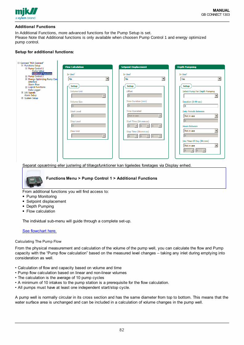
MANUALGB CONNECT 1303
82
Additional FunctionsIn Additional Functions, more advanced functions for the Pump Setup is set.Please Note that Additional functions is only available when choosen Pump Control 1 and energy optimizedpump control.
Setup for additional functions:
Separat opsætning eller justering af tillægsfunktioner kan ligeledes foretages via Display enhed.
Functions Menu > Pump Control 1 > Additional Functions
From additional functions you will find access to:Pump MonitoringSetpoint displacementDepth PumpingFlow calculation
The individual sub-menu will guide through a complete set-up.
See flowchart here.
Calculating The Pump Flow
From the physical measurement and calculation of the volume of the pump well, you can calculate the flow and Pumpcapacity with the “Pump flow calculation” based on the measured level changes – taking any inlet during emptying intoconsideration as well.
• Calculation of flow and capacity based on volume and time• Pump flow calculation based on linear and non-linear volumes• The calculation is the average of 10 pump cycles• A minimum of 10 intakes to the pump station is a prerequisite for the flow calculation.• All pumps must have at least one independent start/stop cycle.
A pump well is normally circular in its cross section and has the same diameter from top to bottom. This means that thewater surface area is unchanged and can be included in a calculation of volume changes in the pump well.

MANUALGB CONNECT 1303
83
As Mµ Connect measures the water surface level in the pump well, then a single calculation based on changes in level(dl) over time (dt) together with a fixed value for the pump well cross-section will give a pretty precise picture of thevolume change – and thereby the flow in the pump well.For the flow measuring, a known volume between two levels is entered. This way, the pump controller is capable ofmeasuring the flow based on the measured level changes. In the flow calculation, the possibility of intake duringemptying is taken into consideration.
To measure the flow, the following prerequisites must be fulfilled:1. All start and stop levels must be outside the area of the flowcalculation. Meaning, the flowcalculation can only be done between the lowest start level entryand the highest stop level entry.The connected pumps must run alone regularly in order to get areliable flow measuring.
2. The drawing shows a pump well with markings of the start andstop levels for 2 pumps, and a marking of the flow measuringarea.
200 cm High level alarm, (set) 150 cm, Start level for pump 2 120 cm, Start level for pump 1 80 cm, Start of the flow measuring level area for volumemeasurement35 cm, Stop of flow measuring30 cm, Joint stop level for all pumps
To make sure the calculation is precise, it is important that the water surface area remains unchanged in the flowcalculation area. Therefore, the flow calculation area must be chosen between two levels in the pump well that do notcontain intake pipes or other components that influence the surface area.Furthermore, the calculation area needs to be within the start and stop limits of the pump. This way the pump is eitherstopped or started to achieve a constant flow during the flow calculation.

MANUALGB CONNECT 1303
84
Flow Calculation Parameters
Menu Item Choice Default Description
In use Yes/No No Choose if the function pump flow calculation should be activated
Volume unit Chose preferred units
Volume size Enter known volume. Must be a value between start and stoplevels.
Start level Start level of known volume.If the control is set for intake, the start level is the lowest accepted level.If the control is set for emptying, the start level is the highest accepted level.
Stop level Stop level of known volume.If the control is set for intake, the stop level is the highest accepted level.If the control is set for emptying, the stop level is the lowest accepted level.
Flow Unit Choose the preferred unit for the flow.
Set Point Displacement
The function is used to increase the amount of waste water in the sewer system during e.g. heavy rain. Therebyoptimizing the flow for the waste water plant.If this function is activated all start and stop levels will be displaced to a level set in Offset for the period of time set inTime Duration. This function is typically activated by a SCADA plant e.g. via data-net communication. A predefined period of time can also be selected for start and stop.

MANUALGB CONNECT 1303
85
Menu Item Choice Default Description
In Use Yes/No Activate the setpoint function.
Offset
Time Duration(min)
0- 59999 Set time for Offset. Will stop when duration is reached.
Time Operated In use/Not inuse
Displacement activation setting – using 24-hour clock, setstart/stop time
Start time(hh:mm:ss)
hh:mm:ss
Time for activating the function.
Stop tidspunkt hh:mm:ss
Time for de-activating the function.

MANUALGB CONNECT 1303
86
Depth Pumping
The function is used to order the pumping well emptied to a point below the normal stop point in order to be capable ofe.g. removing sediments after a pre-decided number of starts, a pre-set time or clock.
Menu Item Choice Default Descrption
In Use Yes/No Activate the Depth pumping.
Select Pump forDepth Pumping
0-2 (8) Choose the output (which pump) to perform the depth pumping.Only 1 pump can be chosen at the time.
Duration (0-99sec.)
0-99sek.
Choose the duration of the depth pumping in seconds after the normal stop level isreached; the depth pumping will start on the selected pump.
Duty periodsbetween
0-9999 Choose the number of starts between depth pumping on theselected pump. Counted on the select DO
Hours Between 0-9999 t Choose the interval between depth pumping in hours.
Use Time OfDay(hh:mm)
Yes/nohh:mm
Clock-timing for activating the function

MANUALGB CONNECT 1303
87
Pump Control 2This function is a simple pump control based on level measurement and start-stop levels.Can be used simultaneously with Pump Control 1. No more than 8 pumps or valves can be controlled in Pump Control 2.
Menu Item Choice Default Description
In Use Yes/No Activate Pump Control 2
General AI 1-6 Noneselected
Select the used AI for Pump Control 2Mµ Connect RTU unit provides 3 AI and can be expanded with further I/Omodules to provide up to 16 AI.
Using Instrument Link: AI # specifications: Unit, decimal, and average is set in I/O Signals>Analogue input
Number ofpumps
1-8 0 Select number of pumps for Pump Control 2Mµ Connect RTU unit provides 2 DO and can be expanded with further I/Omodules to provide up to 32 DO 8 pumps are the maximum selectable amount(8DO)
Number ofsimultaneouslyworking pumps.
1-8 Select the maximum number of pumps to be activated simultaneously for Pump Control 28 pumps are the maximum selectable amount (8DO) I/O Expansion moduleproviding DO is needed for this function.
Display Opsætning Pumpestyring 2
Functions menu > Pump Control 2
Set-up of Pump Control 2 is done in the Display units functions menu. Use the sub-menus to set-up the full function the menu items is similar to the menu items in Instrument Link.
Adjustments can be done individually from Pump Control 2 main menu and is saved automaticallyltvis fra Pumpestyring2 hovedmenu og gemmes automatisk.
Display Flowchart of Pump Control 2 here

MANUALGB CONNECT 1303
88
Pump Set UpOpsætningsparametre for Pumpeopsætning:
Menu Item Choice Default Description
Pump setup Choose the basic settings for the individual pump in Pump Control 2.The amount of controllable pumps is set in Number of Pumps.
Control Output(DO)
1-2(8)
Select the relay to control the pump.Set-up the chosen relay in I/O Signals>Digital Outputs(8) Needs I/O expansionmodule providinDO.
Start Level Activation level of the pumps or valves.If the start level is set higher than the stop level, the pump controller is configuredfor emptying.If the start level is set lower than the stop level, the pump controller is configured forfilling.
Stop Level 0 Level for stopping the pumps or valves..
Delay (sec.) 0- 59999 0 To avoid short term failure modes or level exceedances activating the relays, adelay can be set. If the assigned pumps should not start simultaneously due tostrain load, the delay can be set differently for each relay.
PumpAlternation
In use /Not inuse
In Use When choosing alternation, the alternation will be between all DO outputs selectedin Pump Control 1.The output relays can be set for not in use or in use.If “not in use” is selected, the start and stop level values entered for the individualrelay are the ones that activates the DO relay – and only that specific relay.When using alternation the alternating pumps are activated in a cycle, so that whena start level is passed, the next relay in the cycle is activated. If several start levelsare passed, several pumps will be activated.
Connect Pump set-up using Display
pump control 2 > Pumps Setup
Pump set-up is a part of the menu item Pump Control 2 in the Display unit.Adjustments can be done individually from the Pump Control 2 menu. Complete the set-up set-up and create OverviewScreen.
Display Flowchart of Pump control 2 see here.

MANUALGB CONNECT 1303
89
Energy Optimized Pump ControlIs a way of controlling the waste water pumping and at the same time saving energy.Make the perfect operating conditions to control the frequency converters in an energy saving way.Energy optimized waste water pumping is controlling the well emptying process.There are certain prerequisites to achieve the energy optimization; there must be a frequency converter on each pump,an electromagnetic flowmeter on the exit pipe from the pumping station and an exact and correct level meter.
Principle of energy optimizingThe Function Energy optimized wastewater pumping is chosen to move more water for less money, meaning a similarratio between KW consumption and ft³ and pumped water.The actual values are constantly gathered using the MODBUS connection, connecting the Mµ Connect, MagFlux andthe frequency converter. This way the Mµ Connect will Be capable of adjusting the usage of the frequency convertersconstantly according to the actual conditions (considering too large inlet flow, worn out pump impellers, etc.)The graph shows theproportions between thefrequency and the KW/m³.
Using the MJK MagFlux electromagnetic flowmeter will create a further advantage when used with the built-in MODBUScommunication. This communication is standard in Mµ Connect and MagFlux. Several other frequency converters on themarket are delivered including the MODBUS communications module.
The shown example is based onthe following hardware setup:• Mµ Connect• MagFlux without display• Expert pressure transmitter 7060• Danfoss VLT FC202 Aqua DriveThe MODBUS signals aretransferred using a 2-wire shieldedcable. This decreases the cost ofthe installation, and the size of thebreaker panel.Read more on Danfoss VLTFC202 INET connection

MANUALGB CONNECT 1303
90
Energy Optm. Pump Control Standard Set UpConnect® / Mµ Connect® is measuring the level in the pump well. When the level is above the start level the unit willstart one pump using the MODBUS communication to the frequency converter. The frequency converter starts running atfull speed (50Hz) to set the water in motion. After the ”start up time” the unit ramps the VFD down to the referencfrekvens. Energy optimization is now in progress. Connect/Mµ Connect is keeping the pumps operating until theminimum level is reached. Hereafter the Mµ Connect lowers the speed of the VFD down to the min. frekvens and pumpsto stop level. This is to avoid too many starts.
When using energy optimization in Mµ Connect the following parameters should be entered ahead of start-up.
When using Energy Optimizing, the following parameters is needed.Parameters for Energy optimized waste water pumping.
Menu Item Choice Default Description
In use? Yes/No Activate the function Energy Optimized Waterwater Pump Control
Analog input AI1-3 (6) AI1 Setup the level measurement.In “Analog Input” the individual analogue 4-20 input can be configured.“Scaling” provides an option of changing the units from e.g. m to cm.
Antal pumper 1-8 Number of pumps used with frequency converter to achieve energy optimizedoperation.
Note: For ON - OFF control of VLT, choose DO in additional functions> Control Signals
Energy optimized pump control using the Display device
Functions menu > Optm. Pump Control 3
The Set-up procedure on Display is similar to Instrument Link, flowchart over selve menuen ses her.

MANUALGB CONNECT 1303
91
Energy Optimized Pump Control - Level Parameters
When reaching ”Max level” all pumps will start at maximum frequency (normally 50 Hz)Menu Item Choice Default Description
Maximum Level Max level at normal operation (levels above the entered value will stop energyoptimized operation)At “Max Level” all pumps will start on maximum frequency (normally 50Hz)
Start Level “Start level” will start the pump at 50Hz for x seconds, after this operation thefrequency will be lowered to the reference frequency.Please note that there must be an adequate difference between start and stoplevels to avoid damages to the pumps and relays.
Preferred Level Preferred level is the reference level that should be the “desired level” during pumpoperation.
Minimum Level Minimum Level is regulating down to the minimum frequency. (Hz. Lowest, chosenrotation/capacity for the pumps)
Stop Level “Stop Level” will stop the pumps to avoid running dry. Note that there must be anadequate difference between start and stop levels to avoid damages to the pumpsor relays, and that the stop level cannot be lower than allowed by the producer ofthe used pumps.
Functions menu > Optm. Pump Control 3 > Level Parameters
The Level settings in the Display unit is similar to Instrument Link.flowchart of Display menu here.

MANUALGB CONNECT 1303
92
Control Word
Activation of Control Word will open a new window in the Menu Optm. Pump Control 3 > Pumps setup, this window issimilar to the standard control word window. See specific details here.
Menu Item Choice Default Description
In Use Yes/No No Activate Control Word menu
Number of retries 0-9 0-9 0 Number of retries accepted before the Control Word function willautomatically be activated
When using the Display unit follow this path:
Functions menu > Optm. Pump Control 3 > Control Word
When using the Display unit, set-up of Control Word is done in a guided procedure, in Instrument Link it is made in 2separate steps. The Set-up is similar to Instrument Link, flowchart of Display menu here.

MANUALGB CONNECT 1303
93
Frequency ConverterFor energy optimizing a selection of frequency converter can be used.The selected VFD must be equipped with MODBUS RTU communication interface.
Example: The selected frequency converter is Danfoss VLT FC202; Mµ Connect already holds the necessary register,making communication between the units straightforward. If the VFD doesent appear in the list, select “other”Control signals – start/stop signals for the frequency converter can be chosen in the chpt. Additional Functions – Controlsignal – either via MODBUS or as a DO.All VFD’s have individual parameters that need to be set on the converter itself. For example motor data, Ramp up time,ID-number and communication.
Read more: MODBUS network. electric connectionMenu Item Choice Default Description
Type Danfoss FC202Omron V1000ABB ACS550SCHNEIDER ATV71FLYGT PS200Other Units
Danfoss FC202 Danfoss FC202 frequency converterOmron V1000 frequency converterABB ACS550 frequency converterSCHNEIDER ATV71 frequency converterFLYGT PS200 frequency converter“Others” referring to a generic driver for frequency converterwithout MODBUS communication.
Call onalarm
In Use Not In Use
In Use Choose whether you wish an alarm message (For example anSMS when an error at VLT or the connection occurs).
Alarm Delay hh:mm:ss:m:s 0:0:0 To avoid short term failure alarms, setup a delay for the alarm
Alarm Name VFD Alarm Name the alarm for the SMS message. The name should be adefining name for example “frequency converter failure”
Frequency Converter Using the Display unit
Functions menu > Optm. Pump Control 3 > Frequency Converter Type
The set-up is similar to set-up using Instrument Link, flowchart over Display menuen ses her.

MANUALGB CONNECT 1303
94
Flow InputAnother parameter is the flow measurement from the pumping well, use e.g. a MJK MagFlux connected using RS-485for Mµ Connect. A different flow meter can be connected using I/O.
Menu Item Choice Default Description
Type MJK MagFluxOther UnitsNot in Use
MJK MagFlux When selecting MJK MagFlux flowmeter, note the flow direction.When selecting Others, AO and DO must be defined
Call on Alarm Not in UseIn Use
Not in Use Select “In use” to receive an alarm call when activated.
Alarm Delay T:m:s 0:0:0 To avoid short term failure alarms, set-up a delay for the alarm
Alarm Name Flow Alarm Enter Alarm Name here; this will be stated in “Alarm Cause” on theSMS and when attaching the Connect Display unit.
On the Display unit the Flow input is set-up this way.
Functions menu > Optm. Pump Control 3 > Flow input
Choose between MJK Converter or "Other Units", the guide from these two choices will vary as Connect unit providesextended communications options working with MJK units, hence fewer settings is necessary at a pure MJK set-up.The set-up is similar to Instrument Link, flowchart of Display menu.

MANUALGB CONNECT 1303
95
Adaptive Energy OptimizingAccording to a variable the frequency will be increased or decreased (Normally app. 1Hz) compared to the referencelevel. The operation will continue using the new frequence for app. 1 minute. New measurements will be made duringthis time and the new ratio will be held up to ratio of the reference frequency. If the new frequency is better than thereference frequency the new frequency will automatically be used as new reference frequency.Example:Start 33 Hz (referencefrequency) – trim activeControl at 34 Hz – not goodControl at 32 Hz – betterControl at 31 Hz – betterControl at 30 Hz – not good
Mµ Connect hereafter chooses 32Hz as new reference frequency.
Menu Item Choice Default Description
In Use Yes/No Yes will activate Adaptive energy optimizing
Time betweenoptimizing
0-999timer
0 Number of hours between the automatic optimizing routine.0= continiusly optimizing
Hysteresis 1-9 Hz 0 Amount of HZ for each step during automatic optimizing.Typical 1Hz.
Adaptive energy optimizing using the Displayenheden is setup by following this path:
Functions menu > Optm. Pump Control 3 > Adaptive Optimizing
Hysteresis can only be set-up using Instrument Link.The rest of the set-up is similar to Instrument Link, flowchart of Display menu.

MANUALGB CONNECT 1303
96
Wash Out FunctionWash out function is used with great advantage when using frequency control of pumps, as sediment in the pipes canappear due to e.g. slow flow. The wash out function will help keeping the pipes clean.The wash out routine will start on a defined time of day, and will run once daily. If a pump is already in use on thedefined time, this pump will be stopped and the level will increase until the start level. After this the pump will beactivated on the maximum frequency and operate on this until the routine is completed. At the same time the kWconsumption will be measured for later energy calculations.
Menu Item Options Default Description
Wash Out starttime
hh:mm:ss 0:0:0 Time of day for starting the wash out function (24 hour clock)
Wash outduration
0-99 sec. 0 Duration of Wash Out operation
Startup time(0-99 sec)
0-99 sec. 0 Startup time for operation at max speed (operating at 50 Hz – max111 sec.)
Max flow Limit 0- 9,9991E+37 0 When the max level is reached pump 2 will start if max flow is notexceeded
Minimum FlowLimit
0-50 (60) Hz 0 Lowest frequency the pump(s) may opperate at, Consult the pumpmanufacture.
Wash Out function using Display unit and Connect is found using this path:
Functions menu > Optm. Pump Control 3 > Additional Functions > Wash out
Firstly set the starting time, then duration of the wash out.The set-up is similar to Instrument Link, flowchart of Display menu.

MANUALGB CONNECT 1303
97
Pump SetupSet the frequency Hz for the selected pump. (If in doubt consult the manufacturer of the pump for information of Min andMax. frequency)
Menu Item Options Default Description
Preferredfrequency [Hz]
0-59999Hz
0 Reference, optimal frequency.Set this frequency manually based on test operations.
Minimum Frequency
0-59999Hz
0 Lowest frequency (speed) for pump(s)
Maximum frequency [Hz]
0-59999Hz
0 Higest frequency (speed) for pump(s)
Adaptive energy optimizing using the Display unit is set-up by following this path:
Funktions menu > Optm. Pump Control 3 > Pumps Setup
The Pump set-up offers Frequency controlled pumping, the Display unit provides fewer options compared to InstrumentLink, which provides additional Control Word function, the individual DO and Instrument Net can however be set to 0-AUT-MAN.The set-up is in general similar to Instrument Link, flowchart of Display menu.

MANUALGB CONNECT 1303
98
Additional Functions
Depth PumpingThis function is used is the pumping well should be emptied to a point below the normal stop level to removesediment after a predefined amount of starts, operating time or hours.This depth pumping provides the same options as depth pumping in Pump control 1.Control signal
Menu Item Choice Default Description
Control Signal Used to indicate switches of”O-MAN-AUT” in the panel.Will report if the operating conditions are turned off, if there is manual control orautomatic control of e.g. pump 1.
0-MAN-AUT Not inuse/Inuse
Not inuse
In use will activate this function
DI for MAN-switch
1-6 Set the DI to register manual.
DI for AUTO-switch
1-6 Set DI to register automatic operation..IMPORTANT! Same output used for start-stop of VLT
DO for Start -Stopsignal
1-2 Set the DO that can force a shut down of the pump in position 0OR force a start of the pump in position MAN
Reference AO Set the AO for controlling the VFD without MODBUScommunication. This requires I/O expansion module that provideAO.
Depth pumping using Display unit and Connect
Functions menu > Optm. Pump Control 3 > Additional Functions > Depth pumping
Set the individual parameters - the set-up is similar to Instrument Link, flowchart of Display menu.

MANUALGB CONNECT 1303
99
SCADA ParametersAll parameters referred to here can be read via a SCADA system. Parameters can be adjusted from the SCADAsystem. Registerlist
Registerlist (Modbus) in Mµ Connect:Register regarding flow meter [2000 – 2028]Register regarding VFD setup [3000 – 3159]Additional parameters [50000 – 50600]
SCADA systems that support MODBUS RTU can show parameters for Mµ Connect is:IGSS (via 60/61 commandos),BV-system 2000IFix.
Illustrated below using IGSS.

MANUALGB CONNECT 1303
100
Display Read-OutsWhen connecting a MJK Connect display unit using INET it is possible to receive a read-out on the savedenergy. This calculation is based on measurement at 50Hz and at the reference frequency.
m3/Kwh This illustration is created using custom display lines,setup: 3159 as float, 3 decimals, unit -
Finalize the set-up procedure by setting up the Overview Screen on the Display unit connected to the Connect unit, Thiswill provide an overview of the operations and power savings.
Functions menu > Optm. Pump Control 3 > Create Overview Screen
Flowchart of Display menu.

MANUALGB CONNECT 1303
101
Interlock“Interlock” can set-up exchange of commands between two Mµ Connect units. This way one Mµ Connect can takecontrol remotely of e.g. a DO on another Mµ Connect.An example could be waste water regulation in the sewer system when experiencing heavy rain; you may experience apump stopping earlier, to use the pipes as a regular buffer for the system. Note that both of the Mµ Connects is stillworking independently. Another scenario could be raw water well in a water work; Mµ Connect will register the level inthe clean water tank. When the need of water occurs Mµ Connect will send a signal for the drilling, making another MµConnect start the pump.
When using Interlock the Mµ Connect must be configured for transmitting interlock or receiving interlock.
Menu Item Options Default Description
TransmitInterlock
Not inUseIn Use
Not inUse
Select if the Mµ Connect unit should send interlock commandos forother Mµ Connect units
ReceiverInterlock
Not inUseIn Use
Not inUse
Select if the Mµ Connect unit should receive interlock commandos forother Mµ Connect units
ReceivingIntervalTime out [s]
0- 9999sec.
"Time out" is used if a Mµ Connect has not received a “keep the signal” commandfrom another Mµ Connect, to releasing the signal after time out is reached. If a newsignal is received before the time out is reached, the time out will be reset and starta new countdown. Note that the time out must be higher than the sending intervalon the transmitting Mµ Connect unit.

MANUALGB CONNECT 1303
102
Signal Set Up For InterlockInterlock 1-9 opens the configuration of up to 9 individual interlocks
Menu Item Options Default Description
Start InterLockSignal
DI DOAI High AI Low InternalFlagVAI HighVAI Low
DI Select input or function on the transmitter unit, that will activate“InterLock X”
Stop InterLockSignal
DI DOAI High AI LowInternalFlagVAI HighVAI Low
DI Select input or function on the transmitter unit, that will deactivate “InterLock x”. The“Stop InterLock”signal will, when low, will have one unit calling the other unit andsetting an output low. When the receiver receives the stop signal, the receiver willreturn to “normal mode” When the signal is high As long as the signal is high, thecall will happen with the chosen transmission interval. If the interval is set to 10minutes or more, the remote output should therefore be configured as timecontrolled with an on-time of more than 10 minutes (e.g. 15 minutes), so that theoutput is not constantly high if an error should occur such as a broken phone cable.In this way you ensure that the output goes low by itself if the communication fails.With flawless communication the on-time on the remote unit will be initialised ateach call, and the remote output will therefore be high, as long as the controlledsignal is active.
Receiver OutputSignal Type
DO Othersignal
The Receiver Output Signal Type decides which DO or other signal will be activatedon the receiver.Other Signal provides the option of creating set point displacement or temporarilystop pump control 1 or pump control 2 on the receiving unit.
Note: If the same start and stop signal is chosen, the receiver will adjust to the chosen signal. If different start-stopsignals is chosen, the receiver will start on "START" and will stay "ON" until the stop signal is activated.

MANUALGB CONNECT 1303
103
Interlock Transmission Setup
Menu Item Options Default Description
Send Interval 0-9999 min. 0 "Send interval" determines which interval the transmitter unit is using tosend the command to the receiver unit to keep the state of the interlockoutput. Note that time out on the receiver unit must be higher than thesending interval.
Local orRemote
RemoteLocal
Remote Receiver type can either be this unit (local this device) or a remote unit(Remote device).
Send type Dial Up(PSTN/GSM) / Network(RS232/485)
Dial Up Transmitter type determines how often a call is necessary. As an example, itwill be costly to call every five minutes to exchange feedback commandsbetween two units, when talking aboutstopping a waster water pump with overflow, if the communication is doneby Dial-up (PSTN/GSM).
ReceiverPhoneNumber
If the unit is capable of being called through phone or GSM modem, thenumber of the unit is entered here. If the receiver is a slave unit in a group ofunit, the phone number on the group's master and then the slave unit's IDare entered. Please note that only one master Connect unit can remotecontrol other units in other slave groups directly.
Local ID Unique ID number for the Unit
Remote ID If the receiver is connected using network (RS232/485) data radio, thereceivers ID number is written here.
Interlock, Set-up using the Display unit
Functions menu > Interlock
to setup as well transmitter as receiver.
Flowchart of Interlock.

MANUALGB CONNECT 1303
104
Storm Flow Calculation
Mµ Connect can calculate Storm flow by using a digitalinput and an analogue input.
A MJK Level transmitter is in this example providing the levelsignal Mµ Connect®, and a MJK level electrode 501 withlevel relay is mounted exactly where the Storm flowstarts. When this happens, the level measurement is setto zero and flow is measured from the rest of the levelsignal.
Note: Mµ Connect is most often connected to a MJK level meter with a measuring range designed for thepump control. The measuring range is normally higher than necessary for a flow measuring: typical 10meters for the pump control and 10-20 centimeters for the flow calculation.The accuracy on the pump control level measurement is therefore as the entire flow measuring area.

MANUALGB CONNECT 1303
105
Storm Flow Calculation
Menu Item Options Default Description
In Use No / Yes No Select Yes to activate Storm Flow calculation
Activatecalculation (I/O)
DIDOAI highAI lowLogical function
Select the Input connected to the Level Electrode.The Input will activate and reset the level measurement.
Analogueinput
Select the AI, that provides the level signal to the flow calculation.
Flow Unit m3/sm3/hl/sl/minl/hfeet3/hMGallons/dGallons/min
Select Flow unit
Volume Unit lhlklm3feet3gallonsMgallons
Select Volume unit
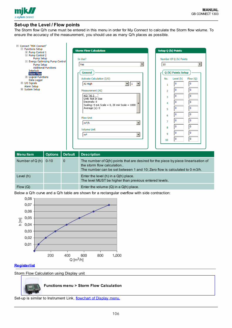
MANUALGB CONNECT 1303
106
Set-up the Level / Flow pointsThe Storm flow Q/h curve must be entered in this menu in order for Mµ Connect to calculate the Storm flow volume. Toensure the accuracy of the measurement, you should use as many Q/h places as possible.
Menu Item Options Default Description
Number of Q (h) 0-10 0 The number of Q(h) points that are desired for the piece by piece linearisation ofthe storm flow calculation..The number can be set between 1 and 10; Zero flow is calculated to 0 m3/h.
Level (h) Enter the level (h) in a Q(h) place.The level MUST be higher than previous entered levels.
Flow (Q) Enter the volume (Q) in a Q(h) place.
Below a Q/h curve and a Q/h table are shown for a rectangular overflow with side contraction:
Registerlist
Storm Flow Calculation using Display unit
Functions menu > Storm Flow Calculation
Set-up is similar to Instrument Link, flowchart of Display menu.

MANUALGB CONNECT 1303
107
Logical FunctionsLogical (PLC) functions provides the Mµ Connect the abilityto solve control functions.
In this menu, simple logical functions such as AND, NAND,OR, NOR, SET/RESET, presets or clock based on differentdigital signals in Mµ Connect is found.
The ability to set internal flags, allows programmingcombinations of more logical functions to achieve a PLClogic functions in Mµ Connect.
The result of the logical function is sent to one of the internalflags, which can be used in other functions or directly to adigital output.
Example: Combined Alarm.A typical use of the logical function is the wish to combine several alarms/statuses so that an alarm is onlysent in critical situations such asthe pump being active, but only uses very little power – a classic example of the pump possibly having lostthe impel.
Menu Item Default Description
In Use No
ActivateCalculation (I/O)
Select the input connected to the level electrode.Input will activate the flow calculation and reset the level measurement.
Analogue Input Select AI, providing the level signal for the flow calculation.
Flow Unit Select Flow unitInternal flag 1 = Logic 1 Signal name = Combi alarm 1

MANUALGB CONNECT 1303
108
Menu Item Options Default Description
Signal name
Output type Not inuse / DO/ logicalfunction
Not inuse
Choose whether the logical function should activate a DOor an internal flag.
Internal flag To improve the possibilities of conducting logicalfunctions, up to16 internal flags can be set. An internal flag is a logicalfunctionwhere the flag is set when a certain combination ofsignals hasbeen achieved – and then these flags are used togetherwith othersignals to conduct the final function. Internal flags can bedescribed as a software relay with memory.
Logic type Choose the PLC function desired to be used betweenlogic signalA and B.See below for explanations of the logical functions
Choose Logical signal 1. (A)
1. Operand
Choose Logical signal 2. (B)
2. Operand.
Delay 0-59999 sec. Set the time interval in which both logical signals mustbe active toset the chosen output type.
AND The output is only high when both A and B are high.Otherwise it islow.
NAND The output is only high when both A and B are high.Otherwise it islow.
OR The output is only low when both A and B are low.Otherwise it ishigh.
NOR The output is only high when both A and B are low.

MANUALGB CONNECT 1303
109
Set -Reset. A simple flip / flop function, Operand 1 sets the function,Operand 2 resets function. Reset holds 1.st priority.Is used for simple on/off control of pumps with flowswitches.
Number of PresetCounts
When the number of presets is reached, a e.g. DigitalOutput will operate in the Close Time. After this, thecount-down will restart.
Number of Presets 0- 59999 Enter number of restarts
Close Time 0- 59999 On-time for the output chosen for the preset counterfunction.
Clock 0- 59999 sek. The built-in clock is a 24-hour clock.When the desired time has been reach, the chosenoutput go onhigh – nomatter the output status.
Start time hh:mm:ss 0:0:0 Time of the day for start of the function.
Stop time hh:mm:ss 0:0:0 Time of the day for stop of the function.
Call on alarm. Not in UseIn Use
Not in Use Chose if an alarm call should be activated if the logicfunction isactived, used for e.g. Combi alarms.
Registerlist (Modbus)• Register Logical functions I/O Status reg.[188–190] [1796–1954]• Register Setup parameters [63498–64208]
Logical functions using the Display unit:
Functions menu > Logical Function
The Menu is created to automatically guide through set-up of up to 9 individual logical functions.Parameters are similar to Instrument Link, flowchart of Display menu.

MANUALGB CONNECT 1303
110
DataloggerMµ Connect and Connect provides 3 individual dataloggers.
Display datalogger.Comli standard RTU loggerModbus standard and event based datalogger

MANUALGB CONNECT 1303
111
Display datalogger
The Display provides a data logger with a capacity of app.160.000 loggings. The Data logger is working following a FIFO principle (first in,first out). If the data logger is full, and more data is entered, thefirst recorded data will be deleted to make space.
Inputs for data logging: Logging interval is set between 10 seconds to 9999 seconds.
The Data log contains:DateTimeAnalogue Value
In case of electrical cut the logger will stop, and continue assoon as the power is reconnected.If additional units is connected to a Display unit, all units willhold individual logging interval which can work for sorting. All units is sharing the memory space of 160.000 loggings.
Log data can be shown directly on the display unit or exported inan external CSV (comma separated) file. MJK – Field Linksoftware is needed to transfer for CSV file, using a USB port inthe display unit.After export the format can be viewed in e.g. Microsoft Excel(MJK Field Link details).
Display data logger.Example of logging capacity at selected intervals
Interval Capacity
Seconds Minutes Hours Days Years
10 19 0,06
30 444 56 0,16
1 1333 111 0,31
5 2667 556 1,54
10 13333 1111 3,09
15 40000 1667 4,63
30 80000 3333 9,26
60 160000 6667 18,52
Functions menu > Data Logger
Flowchart of Display menu.

MANUALGB CONNECT 1303
112
Comli standard RTU datalogger
Input for data logging: AI 1-6Standard data logger operates with fixed intervals and a log of 5minutes.
Log interval, 5 minutes on AI 1-6 analogue input288 registers per AI 1-624 hours capacity
Data log contains:Analogue value
Registerlist (Comli)

MANUALGB CONNECT 1303
113
Comli Extended RTU Datalogger
Extended data logger The extended data logger lets you log witha common variable time interval.Input for extended data logging: AI 1-6
Log interval, 30 sec, 1,5,10,30 or 60 min. on all 6 analoginputs.Runs simultaneously with the 5 min. logger.2880 registers per analog input
Datalog contains:Date (Via MJK Link)Time (Via MJK Link)Analogue value
Registerlist, Comli extended data loggerThese addresses can only be used in connection to IGSS andthe processor type ”MJK-EXTENDED”

MANUALGB CONNECT 1303
114
Comli extended RTU data logger example on log capacity at selected log interval.
Interval Capacity
Seconds Minutes Hours Days
10 8 0,33
30 24 1
60 1 48 2
120 2 96 4
180 3 144 6
240 4 192 8
300 5 240 10
360 6 288 12
420 7 336 14
480 8 384 16
540 9 432 18
600 10 480 20
660 11 528 22
720 12 576 24
780 13 624 26
840 14 672 28
900 15 720 30
960 16 768 32
1020 17 816 34
1080 18 864 36
1140 19 912 38
1200 20 960 40
1260 21 1008 42
1320 22 1056 44
1380 23 1104 46
1440 24 1152 48
1500 25 1200 50
1560 26 1248 52
1620 27 1296 54
1680 28 1344 56
1740 29 1392 58
1800 30 1440 60

MANUALGB CONNECT 1303
115
Comli Time Difference Data Logger
Register list (MODBUS)Extended data logger[xxxx–yyyy]Time difference data loggerLogs countrers and timecounters24 registers per counter24 hours capacity
Data log contains:Date (Via MJK Link)Time (Via MJK Link)Counting and time value
Registerlist, Comli Extended Data LoggerThese addresses can only be used in connection toIGSS and the processor type ”MJK-EXTENDED”

MANUALGB CONNECT 1303
116
Modbus Standard RTU Data LoggerThis extended data logger (currently merely supported by MODBUS driver 76 for IGSS) is providing the option ofoperating with 16 variable signals and time intervals.Choose between fixed time interval and/or event logger in which the time interval depends on an even to occure e.g. adigital signal at storm flow.
This logger is configured from a connected Display.Logging into 20.000 registers sharing he selected amount of signals (1-16)The logged data is date and time in local time from the Mµ Connect.
The shown examples is from IGSS:

MANUALGB CONNECT 1303
117
Modbus Event Based RTU Data Logger

MANUALGB CONNECT 1303
118
I/O SignalsSet-up the functions of the individual digital and analogue input and output. The individual input or output is easilyrenamed, making the set-up more intuitive during normal operations.

MANUALGB CONNECT 1303
119
Digital Input
Menu Item Options Default Description
Signal name DI x Enter the signal name here. It will be shown in Alarm cause on the SMS andwhen connecting a Connect display.
NO/NC NO/NC NO Select relays function for output, as operation current (Normally Open) or(Normally Closed).
Delay (sec.) 0-19999 0 To avoid that short error statuses or level overflows activate the relays, a delaycan be set.
Call on alarm Not in UseIn Use
Not inUse
Choose whether an alarm call should be made on activation.
Digital input I/O signals is configured on the Display unit using this path:
Signals (I/O) > Digital Input
This is similar to Instrument Link, flowchart of Display menu.

MANUALGB CONNECT 1303
120
Digital Output
Menu Item Options Default Description
Signal name DO 1-2 DO x Enter the signal name. Is shown when connecting the Connect display.
NO/NC NO/NC NO Choose the relay function for the output as work voltage (Normally Open) orrest voltage (Normally Closed).
Function Constant/ Timecontrolled
Constant If Constant is selected, DO will be controlled by the connected function inthe main functions.When time controlled is selected, DO will shut down when the time runsout.
Close Time(s.)
0-59999 0 Select time for On time on DO
Delay (s.) 0-59999 0 To avoid short term failure or short term exceeding of levels will activate therelays, a delay can be set.
Digital Output I/O signals is configured using this path:
Signals (I/O) > Digital Output
The set-up is similar to Instrument Link, flowchart of Display menu.
Note that the expression Close Time in Instrument Link and Closed time in Connect

MANUALGB CONNECT 1303
121
Analogue Input
ScalingMenu Item Options Default Description
Signal name AI 1-6 AI x Enter the signal name. Is shown when connecting a Connect display.
Unit type LevelFlowVolumeOtherunits
Select units
Unit Select unit for the chosen type
Decimal Point 0-8 Select number of decimals
4 mA Scaling Value of 4 mA of the chosen unit in Unit type
20 mA Scaling Value of 20 mA of the chosen unit in Unit type
Average (s.) 0- 59999 To avoid that short error statuses or level overflows activate the relays, a delay canbe set.
High / Low alarm Exceeding the analogue level is registered.Menu Item Options Default Description
In Use? Yes / No No
Signal name AI x H. /L.
Enter the signal name, this will be shown in "Cause of alarm" on SMS and whenconnecting the Display to the Connect unit.
Set point
Delay(s.)
0- 59999 0 To avoid that short error statuses or level overflows activate the relays, a delay canbe set
Opkald Not inUsein use
Not inuse
Choose whether an alarm call should be made on activation.
Set Point Limitations Is used to limit the set-up of start/stop levels and analogue limitsMenu Item Options Default Description
Low 0
High 1000
Analogue input I/O signals is configured using the Display unit via this path:

MANUALGB CONNECT 1303
122
Signals (I/O) > Analog inputs
From this menu choose set-up of scaling, high alarm, low alarm and set point limitation. The procedure is similar to Instrument Link, flowchart of Display menu.

MANUALGB CONNECT 1303
123
Analogue OutputExample on activation of proportional AO according to AIif a proportional analogue output according to e.g. Level is needed use the State MachineAI 1 (Level) is read on register 264.This value is written to AO1 (analogue Output 1) in register 628
Data Signal No. Function
0 SM 1 state( 0) reg: 40000 END NOT USED 0
0 SM 1 data( 0) reg: 40002
301989888 SM 1 state( 1) reg: 40004 READ ADR->F32REG NOT USED 0 264
264 SM 1 data( 1) reg: 40006
318767104 SM 1 state( 2) reg: 40008 WRITE F32REG->ADR NOT USED 0 628
628 SM 1 data( 2) reg: 40010
0 SM 1 state( 3) reg: 40012 END NOT USED 0 0
0 SM 1 data( 3) reg: 40014
AO 1 is scaled and min/max limits for AO is set.If AI 1 is scaled 0 to 1000 the chosen AO must be set accordingly.If the AO is used as amplifier, 20 mA can be scaled to 500. This way AO will provide 20 mA when AI is 12 mA.

MANUALGB CONNECT 1303
124
Analogue OutputMenu Item Option Default Description
Signal name Depending onconfiguration
AO X Enter the signal name. Is shown when connecting a Connect display.
Unit type LevelFlowVolumeOther units
Select units
Unit Choose unit for the selected type
Decimal Point 0-8 Scaled value is rounded to the selected number of digits.
4 mA Scaling 4 mA value for the selected unit in unit type.
20 mA Scaling 20 mA value for the selected unit in unit type.Måleområde begrænsning
Menu Item Option Default Description
Low 0
High 0
Configuration of analogue output I/O signals using Display unit
Signals (I/O) > Analog Outputs
From this menu choose set-up of scaling and set point limitation. The set-up is similar to Instrument Link, Ramp time is set using the Display Unit. flowchart of Display menu.

MANUALGB CONNECT 1303
125
Virtual Analogue InputConfiguration.Display navigation for the Connect unit provides the option of setting up to 16 different virtual inputs. The Virtual Analogue inputs is providing a significant expansion of the capacity, and can be used for various individualpurposes including high/low alarm, these are similar to the ordinary analogue inputs, but besides that Function Type canbe selected.
ScalingMenu Item Option Default Description
Function type Not inUseAIdifferenceRegisterAddress
Not inUse
AI difference, is based on the difference between two AI.
Scaling
Signal name VAI 1-6 VAI x Enter the signal name, this will be shown in "Cause of alarm" on SMS and whenconnecting the Display to the Connect unit.
Unit type LevelFlowVolumeOtherunits
Select units
Unit Select unit for the chosen type
Decimal Point 0-8 Scaled value is rounded to the selected number of digits.
Dividing factor
High / Low alarm logging of analogue limit.Menu Item Option Default Description
In Use Yes / No No
Signal name VAI xH. / L.
Enter the signal name, this will be shown in "Cause of alarm" on SMS and whenconnecting the Display to the Connect unit.
Value
Delay(s.)
0- 59999 0 To avoid that short error statuses or level overflows activate the relays, a delay canbe set
Call Not inUseIn Use
Not inUse
Choose whether an alarm call should be made on activation.
Note: it is now possible to do data logging VAI from Display data logger. Flowchart for VAI

MANUALGB CONNECT 1303
126
Alarm CallWhen an alarm is activated, an alarm flag is set. This alarm flag stays high until the alarm is signed. Although the alarmstatus is cleared, the alarm flag stays high until a confirmation has taken place.For both types of signals the following is true; number of active statuses and the amount of time the signal has beenactive, are both registered. During an alarm status, the unit (if an alarm call is chosen) will call the first number in thecall list, then the second, etc.By calling a modem, it is the task of the Scada System to clear the alarm and stop the call routine. When calling SRO/PC (SRO= Scada) or phone number, the routine is stopped by calling back to the control and monitor unit. This doesnot clear the alarm, but only stops the call routine.
If an alarm is activated while the call routine is taking place, the calls will continue as planned. This means that the newalarm will not be reported by call until the next number in the call list.
Menu Item Options Default Description
Call at Alarm Off Call when the alarm status is normal again. Call at alarm off can be turned on oroff.
Call at VoltageDrop
If the net voltage AC or DC is lost, a call can be initiated. This requires aconnected backup battery.
Call at LowBattery
If the connected backup battery voltage falls below 11.5 VDC, acall can be initiated.
Call at AutomaticAlarm Reset
If an alarm has not been reset and 9 more alarms are activated, meaning a totalof 10 non-reset alarms and the 10th alarm therefore can’t be viewed in the alarmlist, the alarm is reset automatically if the function ”Automatic Alarm Reset” hasbeen activated.The function can also be used if no signing is used for alarms.
Alarm call via the Display unit
Connect Configuration > Alarm Setup
From this menu item, configure the Call List using the guided menu From Alarm Call menu it is also possible to activate different types of call alarms.the set-up is similar to Instrument Link, flowchart of Display menu.
Register for alarm handling

MANUALGB CONNECT 1303
127
Call ListAt alarm calls, the defined numbers in the call lists are called in the order they are set in.The communication module connected to the unit is auto detected.The menu “Call type” is only available when a GSM/GPRS communication module is available.
Menu Item Options Default Description
Call Type Four different call types are available. Please see below.
PC (SCADA) Chosen for calls to Scada systems.
Phone Number Number of the receiver.
SMS Enter the SMS text up to 18 characters.The SMS message will be shown on the cell phone on 4 lines:Tag name (entered in General/Name)Alarm cause (entered under Signal name)Mµ Connect (Unit type)Start: hh:mm - dd:mm:yyyy (time and date for sending the message).If the SMS messages are not being sent, then check the SIM card in a cell phone.When sending SMS messages, the messages are delivered to an external server,which means that the unit does not have the ability to test that an SMS messagehas been received by the recipient.
Group SMS Is chosen for up to 16 simultaneous SMS messages with the same text asdescribed under ”SMS”.
Call Is chosen for calls to a land line phone. The subscription should have show-number functionality enabled.
Call interval(min.)
0-9999min.
Enter a delay between calls. Typically 5 minutes

MANUALGB CONNECT 1303
128
SMS text exampleThe screendump shows a SMS for iPhone.
The shown phone number is the SIM-card in the Mµ Connect /Connect. If the number is saved in the phones "contact-list" aname will be shown e.g. the place of the provider of the alarm.
Line 1: Unit Name
Line 2: Signal Name
Line 3: SMS text (as provided on the previous configuration)
Line 4: Start time and date for alarm
Line 5: Stop time and date for alarm

MANUALGB CONNECT 1303
129
SMS Group
Menu Item Options Default Description
Number of calls 1-16 0 Choose number of SMS recipients
SMS Enter the SMS text up to 18 characters.The SMS message will be shown on the cell phone on 4 lines:Tag name (entered in General/Name)Alarm cause (entered under Signal name)Mµ Connect (Unit type)Start: hh:mm - dd:mm:yyyy (time and date for sending the message).If the SMS messages are not being sent, then check the SIM cardin a cell phone.When sending SMS messages, the messages are delivered to anexternal server, which means that the unit does not have the abilityto test that an SMS message has been received by the receipient
Telephonenumber
1-16 Numbers of up to 16 individual receipients of SMS

MANUALGB CONNECT 1303
130
System SettingsIs used for basic configuration of the unit itself. The menu should only be used by trained staff, or by a MJK/Xylemtechnician.

MANUALGB CONNECT 1303
131
Communication
Menu Item Options Default Description
Communicationsetup
General setup for communication
Connect ID 1-247 1 Connect ID number is used when having more unitson the same SRO system or BUS connection toidentify the individual unit.
ID sensitive No/Yes No If set to”Yes”, a unique Connect ID must be used.
Master or Slave Choose whether this unit should be Master (the unit that sends outalarms) or a Slave unit connected to another Master via the CNET or INETport.
GSM/GPRS Specific settings for GSM/GPRS communication.
APN navn 0-32 characters,aA-zZ, 0-9
APN = Access Point Name.A unique name given by the GPRS operator for identification on a GPRSnetwork. (only capital letters)
Init string at+cfun=1
Different modems are not necessarily able to talk to each with the defaultsetup. Modems use many different settings and protocols. In order for twomodems to communicate, they must agree on a number of things suchas speed, error correction, compression algorithms, etc. By sending amodem an init string, you can control some of these parameters.
Baudrate 240048009600192003840057600115200
9600 The baud rate or speed at which the serial data is transmitted or received.
Connect timeout 65 S. 0-59999 If GSM/GPRS connection is online, and the communication is stopped formore then the time out period, the modem is reset..
Communication on Display Unit
System Setup > Communication
This configuration is different from Instrument Link as the menu guide also covers SCADA set-up.Flowchart of Display menu.

MANUALGB CONNECT 1303
132
Mµ Connect / Connect as ClientTo connect a Mµ Connect / Connect unit to a fixed IP-adress and TCP-port, (GPRS) :
Including MPLSComplete APN settings.If communications is within a MPLS-net the APN must be the APN provided by the phone distributor.
Without MPLSRuning wihtout MPLS, the APN will typically be named INTERNET.
GeneralThe fixed IP address, which Mµ Connect / Connect should be connected to, is entered as INIT-string, an example couldbe: @10.20.30.40 ”@” is used to indicate to Mµ Connect / Connect, that there must be connected to the following IPaddress.
TCP port is provided as follows:
FW before 844008: is tcp-port = 2000 + ID-number on Connect
FW after 844008. enter the selected TCP-port in register 64370 as an U16.

MANUALGB CONNECT 1303
133
Overview ScreensPredefined overview screens Connect® / Mµ Connect®. Besides this, it is possible to define individual overview screens providing individual content. The following examples iscreated based on a MJK Instrument connected using RS 485 INET.
MagFlux connected to Mµ Connect® / Connect®The MagFlux display connected to MagFlux the ID number should be set to Modbus ID “1 - 4”. After this, the MagFluxcan be configured with the necessary values for AO and DO Disconnect and remove the Display Unit from the MagFlux.
Read the MagFlux manual to learn more on changing the settings.
Process value PV registers for MagFlux, Oxix, SuSix:Primary measured values from the connected units via INET is written to PV registers that can be logged in the displaydata logger.
Adress No. ID number Description Data type Description
2000 202920582087
1234
Device 1 PV 1 ValueDevice 2 PV 1 ValueDevice 3 PV 1 ValueDevice 4 PV 1 Value
F32F32F32F32
Primary value Current flow register[unit is settingdependent]
2014204320722101
1234
Device 1 PV 2 ValueDevice 2 PV 2 ValueDevice 3 PV 2 ValueDevice 4 PV 2 Value
F32F32F32F32
Secondary valueVolume register[unit is settingdependent]
Following examples shows MJK Instruments, MagFlux, shown with current flow and volume.Read-out of current MagFlux flow, as PV.
First select:Index > Setup > System Setup > Overview Screen Setup > Analog signals > Select LineContent > Line 8 > Display > Custom 1Then change to the current screen 6 line 8:Index > Analog signals > Custom > OK > Name (enter e.g. flow, finish by ”Ok” x2) > Enhed > Flow unit > m3/tModbus ID > ID 1-4Register address > 2000 (enter ”2000” finish by ”ok” x2) > Register data type > F32 (integer numbers 32 bit) Decimal Point > 2
Push ”Back” until overview screens is visible. The current flow is now readable on overview screen 6 line 8.To set-up this value in display logger
Red-out of MagFlux counter, as PV.First select:Index > Setup > System Setup > Overview Screen Setup > Digital inputs > Select LineContent > Line 3 > Display > Custom 2Then change to the current screen 4 line 3:Index > Digital inputs > Custom > OK > Navn (enter e.g. flow counter, finish by ”Ok” x2) > Unit Type > Volume unit > m3Modbus ID > ID 1-4Register address > 2014 (Enter ”2014” finish by ”ok” x2) > Register data type > U16 (integer numbers 16 bit) Decimal Point > 0
Push ”Back” until overview screens is visible. The current flow is now readable on overview screen 4 line 3.

MANUALGB CONNECT 1303
134
To set-up this value in the Display Logger
Read-out of current MagFlux flow, as VAI. By choosing current MagFlux flow, as VAI, the value can be used in other menus and functions as well as for defininglimits etc.
If the Display is mounted, an overview screen is selected, here no. 6, add an optional line (8) using VAI 1First select:Index > Setup > System Setup > Overview Screen Setup > Analog signals >Select LineContent > Line 8 > Connect base1 > Virtuel analog input > VAI 1Then change to:Connect Configuration > Signals (I/O) > Virtuel analog input > VAI 1Function type > Register address > 2000 (enter ”2000” finish by ”ok” x2)Register data type > F32 (decimal numbers 32 bit) Scaling > Signal name > (enter e.g. Flow, finish by ”Ok” x2) > Unit Type > Flow unit > m3/tDecimal Point > 2
now the current flow is readable in line 8 on screen 6.
Overview screens Generally configuration via
System Setup > Overview Screen Setup
Overview screens is a guided menu, depending on individual selection, which will ensure step-by-step configuration.

MANUALGB CONNECT 1303
135
Set-up Day Shift Moment
Menu Item Option Default Description
Day ShiftMoment
The default day shift happens at midnight, but can be changed so a day runs from forexample 07:00 to 07:00. Set the delay from midnight in this option
Day shift Moment set-up using the Display unit
System Setup > Dayshift Time
Set-up the time for the individual day-registers to reset and restart.Flowchart of Display menu.

MANUALGB CONNECT 1303
136
SCADA Configuration
Menu Item Options Default Description
SRO System(SCADA system)
StandardSystem 2000IGSS driver13/75IGSSDriver54CITECTSYSTEM2000 60COMMANDUNIVIEWVA ING
StandardSystem2000IGSS driver13/75
A specific register setup for specific Scada systems arechosen here.For example register ID number placement, etc.When choosing Default (System 2000/IGSS driver13/75) no change is made in relation to the standardregister plan.
Number of StatusTelegrams
2 0-7 Number of status telegrams decides how many registers is mailedto the scada-systemet.1 = send register 0 - 31 ind til Scada2 = send register 0 – 63 ind til Scada3 = send register 0 - 95 ind til Scada
Use CustomRegister
No / Yes No For adaptation to specific SCADA Systems, an edit of the register listcan be made.Typically when GPRS transmission is used, the amount of data arereduced.This register is moved to lie in succession, therefore only a fewtelegrams are sent.Is entered manually using Connect® display > technical setup >read/write reg. The specific register list is defined from register 57000 and 287registers ahead. The User specific register list merely covers COMLI.
SCADA Communications configuration on the Display Unit:
System Setup > Communication
The configuration of SCADA is the finalizing part of the communications set-up, the configuration is different fromInstrument Link as Instrument Link besides SCADA system and user specified register and can choose to receivebetween 1-7 status telegrams.Flowchart of Display menu.

MANUALGB CONNECT 1303
137
Set-up Wireless
Menu Item Options Default Description
Wireless SSID aA-zZ, 0-9 MyConnect
For indication of SSID broadcasting (name)
Password 8-18 characters(digits/letters)
Wi-Fi Protected Access II. WPA2(AES)Enter unique code for Mµ Connect. Must be at least 8 characters.
Set-up or adjustments of the configuration will automatically be included in the internal update cyclus after maximum 3minutes, after this the new configuration of the wireless signal is completed.

MANUALGB CONNECT 1303
138
Device Settings
Menu Item Options Default Description
Factory ResetDevice
This function will delete all data and setups and will set the unit todefault factory setup.
Device ModemReset
This function resets the built-in modem..
Scan IOModules
This function scans the I/O BUS for added I/O modules.If you connect I/O modules, these will first be shown in InstrumentLink after restart and transfer of the unit.
Restart Device This restarts the unit.Note: ”Restart Device” will cause all factory settings including adjustment aswell as any other added information to be deleted!

MANUALGB CONNECT 1303
139
Access Code (login)Creation of access codes using the display unit:
From Overview screen select following path:
Index > Setup > 4 > 6 this will access configuration of access codes
Activate > Login enter ”2045”
Change Password Enter the amount of needed access codes. Enter the new accesscodes.
Decide if the device should call a given SCADA when login is performed.
Decide eventual timeout for login.
To log out select login and enter 0000 as code.
To de-activate all pumps during login, choose "activate/deactivate pumps". This will deactivate all pumpsfrom Pump Control 1 will automatically be stopped when login is performed.
Creation of login on overview screen:From Overview screen select following path:
Index > Menu > 4 > 2 To define overview screen
Select Lin content
Select which line the login should be placed on
Select Connect base 1
Other Units > Log in
Now Login is an option directly from the Overview screen
See Flowchart.

MANUALGB CONNECT 1303
140
SMS CommandosOnline data and status from the Connect device can be sent directly as a SMSRequire a SMS status for the devices GSM number showing the text from the "SMS to Connect"-column to receive thereply providing the relevant content from the Connect device.
A SMS showing the text:STATUS DI1 STATUS DI2 STATUS DI3
Will provide 3 reply SMS, one for each selected DI.
SMS commando and replyAction SMS for Connect Reply from Connect (example)
Send online data from Connect ONLINE DATAor"Connect ID-no."
Connect ID xDI 1-8: 00000000DI 9-16: 00000000DO 1-8: 00000000AI1 = 139.53AI2 = 560.55AI3 = 32.43AI4 = 1078.31AI5 = -0.42AI6 = 142.10
Status and operating data from theselected digital input (DI)
STATUS DI# MJK ConnectLABEL: DI xDI x STATUS: OFFCOUNTER:TOTAL: 0TODAY: 0YESTERDAY: 0TIME:TOTAL: 0 hTODAY: 0 min.YESTERDAY: 0min.
Status and operation data for theselected Digital Output (DO)
STATUS DO# MJK ConnectLABEL: DO xDO x STATUS: OFFCOUNTER:TOTAL: 0TODAY: 0YESTERDAY: 0TIME:TOTAL: 0 hTODAY: 0 min.YESTERDAY: 0min.
Action SMS for Connect Reply from Connect (example)
Status and operation data for theselected Analogue Input (AI)
STATUS AI# MJK ConnectLABEL: AI xAI x VALUE: 32.48MAX. VALUE TOTAL: 32.51MAX. VALUE TODAY: 32.51MAX. VALUE YESTERDAY: 32.51
Status and operation data for theselected Analogue high level
STATUS HL AI# MJK ConnectLABEL: AI x H.AI HL x STATUS: OFFCOUNTER:TOTAL: 0TODAY: 0YESTERDAY: 0
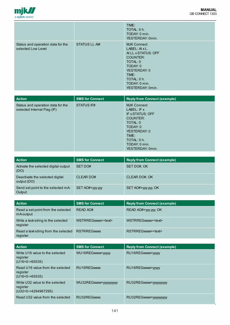
MANUALGB CONNECT 1303
141
TIME: TOTAL: 0 h.TODAY: 0 min.YESTERDAY: 0min.
Status and operation data for theselected Low Level
STATUS LL AI# MJK ConnectLABEL: AI x L.AI LL x STATUS: OFFCOUNTER:TOTAL: 0TODAY: 0YESTERDAY: 0TIME: TOTAL: 0 h.TODAY: 0 min.YESTERDAY: 0min.
Action SMS for Connect Reply from Connect (example)
Status and operation data for theselected Internal Flag (IF)
STATUS IF# MJK ConnectLABEL: IF xIF x STATUS: OFFCOUNTER:TOTAL: 0TODAY: 0YESTERDAY: 0TIME: TOTAL: 0 h.TODAY: 0 min.YESTERDAY: 0min.
Action SMS for Connect Reply from Connect (example)
Activate the selected digital output(DO)
SET DO# SET DO#, OK
Deactivate the selected digitaloutput (DO)
CLEAR DO# CLEAR DO#, OK
Send set point to the selected mA-Output
SET AO#=yyy.yyy SET AO#=yyy.yyy, OK
Action SMS for Connect Reply from Connect (example)
Read a set point from the selectedmA-output
READ AO# READ AO#=yyy.yyy, OK
Write a text-string to the selectedregister
WSTRREGxxxxx=<text> WSTRREGxxxxx=<text>
Read a text-string from the selectedregister
RSTRREGxxxxx RSTRREGxxxxx=<text>
Action SMS for Connect Reply from Connect (example)
Write U16 value to the selectedregister(U16=0->65535)
WU16REGxxxxx=yyyyy RU16REGxxxxx=yyyyy
Read U16 value from the selectedregister(U16=0->65535)
RU16REGxxxxx RU16REGxxxxx=yyyyy
Write U32 value to the selectedregister (U32=0->4294967295)
WU32REGxxxxx=yyyyyyyyyy RU32REGxxxxx=yyyyyyyyyy
Read U32 value from the selected RU32REGxxxxx RU32REGxxxxx=yyyyyyyyyy

MANUALGB CONNECT 1303
142
register (U32=0->4294967295)
Write F32 value to the selectedregister (F32=decimal point)
WF32REGxxxxx=yyy.yyy RF32REGxxxxx=yyy.yyy
Read F32 value from the selectedregister (F32=decimal point)
RF32REGxxxxx RF32REGxxxxx=yyy.yyy

MANUALGB CONNECT 1303
143
State Machine, Sequence ControlThis function allows the possibility of creating sequences (statements) for special controls.
By importing the set-up from a unit, for example state machine programming can be downloaded and saved togetherwith the set-upTo program the up to 10 state machines MJK State Machine Software must be used:
1. Select which State Machine to configure2. Then choose what signal must conduct a resetfunction of the State Machine. If the reset signal is activated state machine willgoto state <data>- Reset signal should be on state0.3. Finally select the states that must be performed.when function, signal type, signal no. and data isentered, select ”Add state”. the programmed states is seen in the example.
Example:In this example a reset state is not set
This state machine will perform the following:1) Wait for DI1 to be activated2) Wait for 10 seconds3) Pull DO 44) Wait for DI5 to be activated or goto next stepafter 30 seconds5) Reset DO 46) Final state. (goto state 1)up to 10 state machines can be programmed.
Readout/set of timer-delays in State Machine First Select:Index > Setup > System Setup > Overview Screen Setup > Overview Screen 2 > SelectLine Content > Line 1 > Display > Custom 1
Then, goto Overview Screen 2 linje 1:Index > Overview screen 2 > Custom > OK > Name (write. Timer1 , Sec. , enter ”Ok” x2) > Unit (Other units, select “None”)Modbus ID (Enter ID no 1, enter “OK” x2)Register address > 4XXXX > Register datatype > U32 Number of decimals > 0Word Swap > No
Enter “Back” to the overview screen is shown. The Timer value can now be read and set by the Overview screen 2 line1. Registerliste

MANUALGB CONNECT 1303
144
Overview Of State FunctionsEach state machine can hold up to 100 states. The total of 16 U16 registers, 16 U32 registers and 16 float registers,these are used when reading/writing to the registerlist.
Function SignalType
SignalNo.
Data Description
ENDSTATE notused
0 0 Any state machine MUST be finalizedwith and END-STATE, as this indicatesthat state machine must goto State 1.
I/O STATUS ON DIDOINTFLAIHAIL
1-xx x The function awaits the activation of the chosen signal.If data = 0 wait for signal to be activated.If data > 0 the <data>state will be activated
I/O STATUSOFF
DIDOINTFLAIHAIL
1-xx x The function awaits the chosen signal tobe de-activated.If data = 0 wait for de-activation.If data > 0 go to state <data>.
SET DO DO 1-xx 0 The function sends activation signal tothe selected DO.
RESET DO DO 1-xx 0 The function sends de-activation signalfor the selected DO.
DELAY WAITON
DIDOINTFLAIHAIL
1-xx seconds
The function awaits <data> seconds for activation of signal.If signal does not appear within set time goto next state.
DELAY WAITOFF
DIDOINTFLAIHAIL
1-xx seconds
The function waits for <data> seconds for signal de-activation.If signal does not appear within set time goto next state.
TIME OF DAY notused
0 seconds fromkl 00:00
The function waits for the selected time of day, then goto next state.
PRESETCOUNTER
DIDOINTFLAIHAIL
1-xx x The function waits for <data> amount of impulses on the selected signalthen goto next state..
PRESET TIME DIDOINTFLAIHAIL
1-xx x The function waits for the selected signal to be active for <data> seconds,then goto next state.
HIGH LIMIT AI1-x 1-6 LimitValue
The function waits for the selected AI to surpass the value of <data>
LOW LIMIT AI1-x 1-6 LimitValue
The function waits for the selected AI to decline to a value set in <data>
GOTO STATE notused
0 state no The function changes to the state set in <data>
SEND ALARM notused
0 0 The function activates an alarm call as configured in the alarm list.
READ ADR ->U16REG
notused
0-15 ModbusAdr
The function stores content of modbus register address <data> inU16REG[signal nr.]
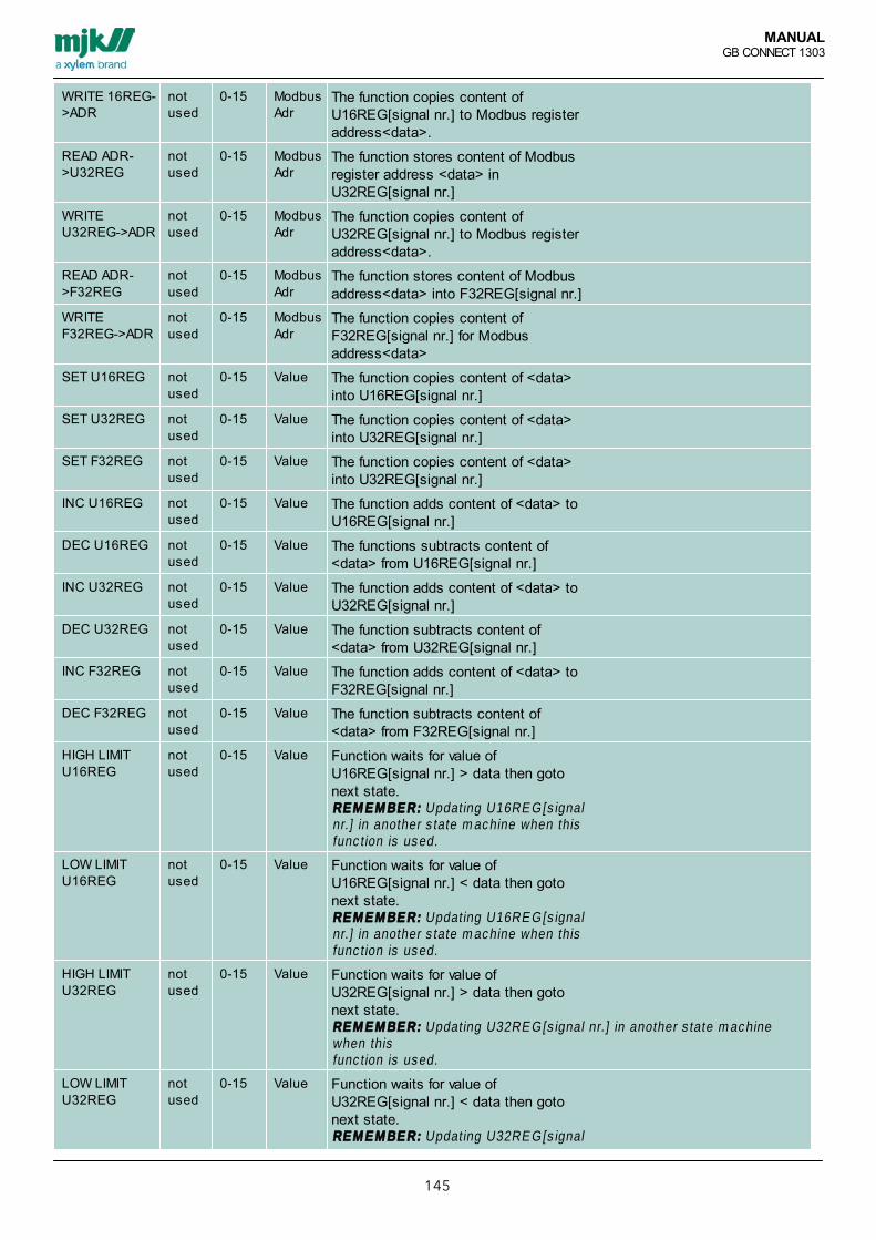
MANUALGB CONNECT 1303
145
WRITE 16REG->ADR
notused
0-15 ModbusAdr
The function copies content ofU16REG[signal nr.] to Modbus registeraddress<data>.
READ ADR->U32REG
notused
0-15 ModbusAdr
The function stores content of Modbusregister address <data> inU32REG[signal nr.]
WRITEU32REG->ADR
notused
0-15 ModbusAdr
The function copies content ofU32REG[signal nr.] to Modbus registeraddress<data>.
READ ADR->F32REG
notused
0-15 ModbusAdr
The function stores content of Modbusaddress<data> into F32REG[signal nr.]
WRITEF32REG->ADR
notused
0-15 ModbusAdr
The function copies content ofF32REG[signal nr.] for Modbusaddress<data>
SET U16REG notused
0-15 Value The function copies content of <data>into U16REG[signal nr.]
SET U32REG notused
0-15 Value The function copies content of <data>into U32REG[signal nr.]
SET F32REG notused
0-15 Value The function copies content of <data>into U32REG[signal nr.]
INC U16REG notused
0-15 Value The function adds content of <data> toU16REG[signal nr.]
DEC U16REG notused
0-15 Value The functions subtracts content of<data> from U16REG[signal nr.]
INC U32REG notused
0-15 Value The function adds content of <data> toU32REG[signal nr.]
DEC U32REG notused
0-15 Value The function subtracts content of<data> from U32REG[signal nr.]
INC F32REG notused
0-15 Value The function adds content of <data> toF32REG[signal nr.]
DEC F32REG notused
0-15 Value The function subtracts content of<data> from F32REG[signal nr.]
HIGH LIMITU16REG
notused
0-15 Value Function waits for value ofU16REG[signal nr.] > data then gotonext state.RE M E M BE R: Updating U16RE G[s ignalnr.] in another s tate m achine when thisfunc tion is used.
LOW LIMITU16REG
notused
0-15 Value Function waits for value ofU16REG[signal nr.] < data then gotonext state.RE M E M BE R: Updating U16RE G[s ignalnr.] in another s tate m achine when thisfunc tion is used.
HIGH LIMITU32REG
notused
0-15 Value Function waits for value ofU32REG[signal nr.] > data then gotonext state.RE M E M BE R: Updating U32RE G[s ignal nr.] in another s tate m achinewhen thisfunc tion is used.
LOW LIMITU32REG
notused
0-15 Value Function waits for value ofU32REG[signal nr.] < data then gotonext state.RE M E M BE R: Updating U32RE G[s ignal

MANUALGB CONNECT 1303
146
nr.] in another s tate m achine when thisfunc tion is used.
HIGH LIMITF32REG
notused
0-15 Value Function waits for value ofF32REG[signal nr.] > data then gotonext state.RE M E M BE R: Updating F32RE G[s ignalnr.] in another s tate m achine when thisfunc tion is used.
LOW LIMITF32REG
notused
0-15 Value Function waits for value ofF32REG[signal nr.] < data then gotonext state.RE M E M BE R: Updating F32RE G[s ignalnr.] in another s tate m achine when thisfunc tion is used.
ADD U16REG notused
0-15 Value Function U16REG[signal nr] =U16REG[signal nr] + U16REG[data]
SUB U16REG notused
0-15 Value Function U16REG[signal nr] =U16REG[signal nr] - U16REG[data]
ADD U32REG notused
0-15 Value Function U32REG[signal nr] =U32REG[signal nr] + U32REG[data]
SUB U32REG notused
0-15 Value Function U32REG[signal nr] =U32REG[signal nr] - U32REG[data]
ADD F32REG notused
0-15 Value Function F32REG[signal nr] =F32REG[signal nr] + F32REG[data]
SUB F32REG notused
0-15 Value Function F32REG[signal nr] =F32REG[signal nr] - F32REG[data]
SET F32REG->V-AI
notused
0-15 Value Function VAI[signal nr] = F32REG[data]RE M E M BE R: S et F32RE G[data] for theneeded value before ac tivating S E TF32RE G-> V -A I.
CONV U16->U32
notused
0-15 Value Function U32REG[signal nr] =U16REG[data]
CONV U32->U16
notused
0-15 Value Function U16REG[signal nr] =U32REG[data]
CONV U16->F32
notused
0-15 Value Function F32REG[signal nr] =U16REG[data]
CONV F32->U16
notused
0-15 Value Function U16REG[signal nr] =F32REG[data], integral number
CONV U32->F32
notused
0-15 Value Function F32REG[signal nr] =U32REG[data]
CONV F32->U32
notused
0-15 Value Function U32REG[signal nr] =F32REG[data], integral numbers.
MULTIPLYF32REG
notused
0-15 Value Function F32REG[signal nr] =F32REG[signal nr] *

MANUALGB CONNECT 1303
147
SoftwareMJK Instrument Link is used for communication between Connect® or Mµ Connect® and a PC using standard USBcable, Wi-Fi and/or PSTN/GSM/GPRS modem.
MJK Smart phone App, provides the option of viewing and editing the configuration as well as viewing online data frompump control Connect® and Mµ Connect® devices.
is used for communication between your MJK instrument to a PC by use of a standard USB cable.
MJK State Machine software provides the option of creating sequences (statements) for special control.

MANUALGB CONNECT 1303
148
MJK Instrument LinkFor general operation of Instrument Link please read the manual DK 6.28 Instrument Link Quick Guide downloadable from:www.mjk.dk/downloads/downloads-products/downloads-accessories/downloads-rtusoftware.html
SpecificationsMinimum system requirements
PC: USB 2.0Microsoft Windows XP sp2/ Vista /Win 7, 32bitMicrosoft .net 3,5 framework, screen resolution 1280x800
Instrument Link including updates is free, the latest releasedversion is at any time downloadable from the address above.

MANUALGB CONNECT 1303
149
MJK Smartphone AppDiagramme for usage of Smartphone App
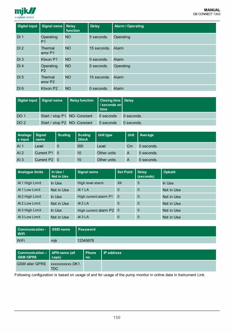
MANUALGB CONNECT 1303
150
Digital input Signal name Relayfunction
Delay Alarm / Operating
DI 1 OperatingP1
NO 5 seconds. Operating
DI 2 Thermalerror P1
NO 15 seconds. Alarm
DI 3 Klixon P1 NO 0 seconds. Alarm
DI 4 OperatingP2
NO 5 seconds. Operating
DI 5 Thermalerror P2
NO 15 seconds. Alarm
DI 6 Klixon P2 NO 0 seconds. Alarm
Digital input Signal name Relay function Closing time/ seconds ontime
Delay
DO 1 Start / stop P1 NO- Constant 0 seconds 0 seconds.
DO 2 Start / stop P2 NO- Constant 0 seconds 0 seconds.
Analogue input
Signalname
Scaling Scaling20mA
Unit type Unit Average
AI 1 Level 0 300 Level Cm 0 seconds.
AI 2 Current P1 0 10 Other units A 0 seconds.
AI 3 Current P2 0 10 Other units A 0 seconds.
Analogue limits In Use / Not in Use
Signal name Set Point Delay(seconds)
Opkald
AI 1 High Limit In Use High level alarm XX 5 In Use
AI 1 Low Limit Not in Use AI 1 LA 0 0 Not in Use
AI 2 High Limit In Use High current alarm P1 0 0 Not in Use
AI 2 Low Limit Not in Use AI 2 LA 0 0 Not in Use
AI 3 High Limit In Use High current alarm P2 0 0 Not in Use
AI 3 Low Limit Not in Use AI 3 LA 0 0 Not in Use
Communication -WiFi
SSID name Password
WiFi mjk 12345678
Communication –GSM /GPRS
APN name (allcaps)
Phoneno.
IP address
GSM eller GPRS xxxxxxxxxx.DK1.TDC
Following configuration is based on usage of and for usage of the pump monitor in online data in Instrument Link.

MANUALGB CONNECT 1303
151

MANUALGB CONNECT 1303
152
Smartphone App - User Interface
Main screen in the Mµ Connect App provides an overview ofthe current operations in the set-up as well as simple navigationfor sub-sides containing detailed information.
The coloured dots on the pumps shows eventual alarms orcurrent power on the connected pumps. A high level alarm will bemarked with a colour and be featured on a list.
1. Select a pump to check and/or adjust the settings for thepump by pressing "i" on the graphic.
2. Alarm History.
3. System Information.
1. The individual pump windowProvides information on operating hours, number of starts on thetop. below this, the conditions for pump activation/deactivationcan be adjusted.
Press the white box, and enter the needed value for high levelalarm, start level and stop level.
Activate or deactivate Alternation
In the bottom manual start/stop/block buttons allows overrulingthe already set configuration.
2. Alarm History Provides an overview of the latest alarms both actual and closedalarms are visible.
The blocks is providing type of alarm, start and eventually stoptime.
The individual alarm is besides that marked with a colour, thecolours will help categorizing the importance of the individualalarm quickly.

MANUALGB CONNECT 1303
153
3. System Information Is providing an overview of the data connection.
Beneath the data overview an overview of the voltage on theindividual inputs is found.
No connection to device"Run Demo-mode" is providing a virtual mode allowingconfiguration which can be changed, thereby used for trainingactions i coherence with alarms.
This mode will of course have no influence on the ordinary controlof Mµ Connect at all.

MANUALGB CONNECT 1303
154
MJK Field Link
Communication software for MagFlux, SuSix, Oxix, mA/BusConverter, Connect and Mµ Connect. Functions
instrument and a PC using standard USB cabel.
Log DataImport and show Log Data an export as CSV file.
Firmware
converters
Specifications Minimum system krav
Microsoft Windows XP sp2/ Vista /Win 7, 32bit Java USB 2.0, MJK USB cable 691095 PC recommended
Download Field Link www.mjk.dkdirect link for the download center
MJK-Field Link does not need installation, the .exe file works as an applicationMJK-Field Link is used for updating firmware on Connect® base, Display as well as language file. download and savingscreen configuration from Connect Display ® display.
Update functionsMJK-Field Link Software contains more update functions which will be described in details on the following pages.Connect base, display device and language file can be updated individually, but on top of a Display device update, thelanguage file must be re-installed.A. Connect PC to Connect base deviceB. Update Connect® base firmwareC. Connect PC to Connect display deviceD. Save log dataE. Update display firmwareF. Update Language firmware
Important ! All screen resolutions is reset when installing new firmware! See procedure A, step 8 on page 183,how to save the current display screen resolution.Existing log data can/must be saved before installing new firmware! Wait for all transfer and programming functions to be completely finished before disconnecting the USBcable. If an update process is running (especially Flash programming) is interrupted it may result in thesystem will block and a MJK technician must be called! To run MJK-Field Link the PC must have Java installed.

MANUALGB CONNECT 1303
155
Data loggerEnter “logData” and “read Log”Data logger in Connect display will be transferredto PC. Wait…Now, you can save data logger as a CSV file.The CSV file can be opened with Microsoft Excel.
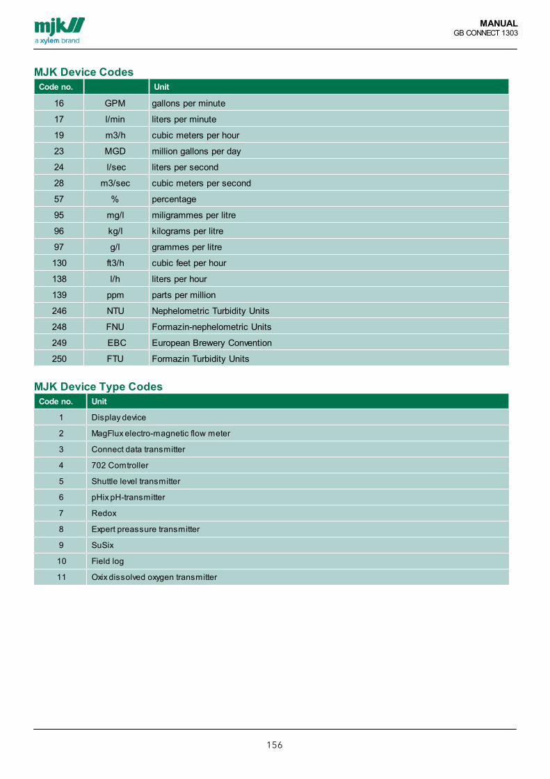
MANUALGB CONNECT 1303
156
MJK Device CodesCode no. Unit
16 GPM gallons per minute
17 l/min liters per minute
19 m3/h cubic meters per hour
23 MGD million gallons per day
24 l/sec liters per second
28 m3/sec cubic meters per second
57 % percentage
95 mg/l miligrammes per litre
96 kg/l kilograms per litre
97 g/l grammes per litre
130 ft3/h cubic feet per hour
138 l/h liters per hour
139 ppm parts per million
246 NTU Nephelometric Turbidity Units
248 FNU Formazin-nephelometric Units
249 EBC European Brewery Convention
250 FTU Formazin Turbidity Units
MJK Device Type CodesCode no. Unit
1 Display device
2 MagFlux electro-magnetic flow meter
3 Connect data transmitter
4 702 Comtroller
5 Shuttle level transmitter
6 pHix pH-transmitter
7 Redox
8 Expert preassure transmitter
9 SuSix
10 Field log
11 Oxix dissolved oxygen transmitter

MANUALGB CONNECT 1303
157
Frequency Log interval in seconds (here: 10 seconds)
Range Max Maximum value for graph
Range Min Minimum value for graph
Precision The accuracy of the SI value
Column J Sensor name as entered by the user
Time Date and time in Central European Standard Time (CEST)
UTime Time in UNIX format. Number of seconds elapsed sinde 00:00:00 d. 1 January 1970
SI Value The value in SI units (Système International d’Unités)

MANUALGB CONNECT 1303
158
BluetoothOpen ”This computer”
Open ”Bluetooth places”
Select ”Show bluetooth units”

MANUALGB CONNECT 1303
159

MANUALGB CONNECT 1303
160
Bluetooth units:
Connect to the desired unit (right-click)

MANUALGB CONNECT 1303
161
Type code (default = 1000)
Double-click (left) on the desired unit to open the services:

MANUALGB CONNECT 1303
162
Double-click (left) COM1 service to connect to service:
(remember to disconnect COM1 service before connecting to a new unit)
Remember the new COM-port (COM9)

MANUALGB CONNECT 1303
163
Start MJK-Field-Link and choose “Mount Serial/Bluetooth”

MANUALGB CONNECT 1303
164
Select the new COM-port (COM9 in this example):
(it is possible to use "Auto").
MJK-Field Link is now connected:
MANUALGB CONNECT 1303
165
Update LanguageAll languages will be deleted during a display firmware update. As a consequence the required languages needreinstalling via the service programme Field Link.
1. Select ”File” and click ”Languages”2. A dialog box appears showing the status of the installed languages (there are no installed languages after a firmwareupdate).3. Click ”Add”, locate the desired language text file or language pack on the CD (for example ”84151-003 Text file) andclick ”Open”.4. Select a language or a language pack (Connect) from the dialog box and click OK.5. The selected languages are then transferred and installed. If required, it is possible to remove languages from the listwith ”Delete” and ”Close”.6. Select ”Dismount USB” followed by ”Exit” to finish the Connect firmware update.
Please note: If requested an updated language text file will be sent from MJK

MANUALGB CONNECT 1303
166
MJK State Machine SoftwareSpecifications
Minimum system requirementsPC: USB 2.0 connectionMicrosoft Windows XP sp2/ Vista /Win 7,32bit
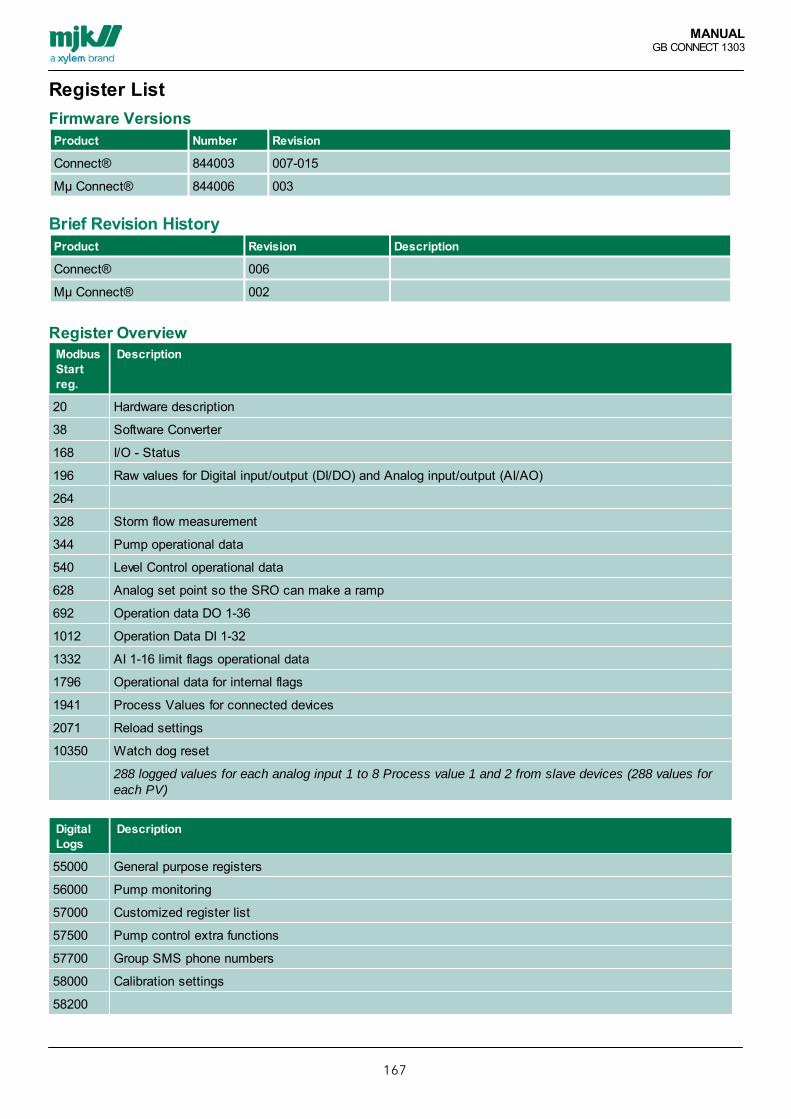
MANUALGB CONNECT 1303
167
Register ListFirmware VersionsProduct Number Revision
Connect® 844003 007-015
Mµ Connect® 844006 003
Brief Revision HistoryProduct Revision Description
Connect® 006
Mµ Connect® 002
Register OverviewModbusStartreg.
Description
20 Hardware description
38 Software Converter
168 I/O - Status
196 Raw values for Digital input/output (DI/DO) and Analog input/output (AI/AO)
264
328 Storm flow measurement
344 Pump operational data
540 Level Control operational data
628 Analog set point so the SRO can make a ramp
692 Operation data DO 1-36
1012 Operation Data DI 1-32
1332 AI 1-16 limit flags operational data
1796 Operational data for internal flags
1941 Process Values for connected devices
2071 Reload settings
10350 Watch dog reset
288 logged values for each analog input 1 to 8 Process value 1 and 2 from slave devices (288 values foreach PV)
DigitalLogs
Description
55000 General purpose registers
56000 Pump monitoring
57000 Customized register list
57500 Pump control extra functions
57700 Group SMS phone numbers
58000 Calibration settings
58200

MANUALGB CONNECT 1303
168
Set upParametre
Description
58500 Setup Parametre Extended Data logger
59000 Analog input setup parameters
60408 Digital input Setup parameters
60888 Digital output setup parameters
61528 Analog output setup parameters
62200 STD. Pump control setup parameters
62587 Level Control
62902 Alarm Control
63215 Data logger Standard
63219 Interlock
63498 Logical functions (1-16)
64218 Storm flow calculation
64356 System parameters
65449 Texts
For a complete register, please see separate document
DK 844003
Connect Rev.007-015
Mµ Connect 844006 Rev. 003 Register list
Can be found on the following link:
www.mjk.dk/downloads/downloads-products/downloads-rtu/downloads-connect.html

MANUALGB CONNECT 1303
169
General Description Of Comli ProtocolComli Description
Standard Baudrate 9600
Standard Formatfor Serial:
1-Startbit, 8-Databits, 1-Parity (Even), 1-Stopbit
Password By default OFF
CommandsName Description
48 - Write registers Used for write/reset operation data and logs as unsigned word (16 bit)
50 - Read registers Used for read operation data and logs as unsigned word (16 bit)
51 - Write bit Used for set/reset of a I/O signal. For example DO and alarm status
52 - Read bit Used for read status on I/O for example DI, DO, AI high/low limit and IF (internal flags)
60 - Read RAM Used for read operation data and setup of parameters as unsigned word (16 bit), unsigneddouble word (32 bit) or Float (32 bit) depends on register type.
61 - Write RAM Used for write operation data and setup of parameters as unsigned word (16 bit), unsigneddouble word (32 bit) or Float (32 bit) depends on register type.
73 - Read time/date
Read time and date for Connect
74 - Write time/date
Write time and date for Connect
Data TypesName Description
U16 Unsigned word (16 bit)
U32 Unsigned double word (32 bit)
F32 Float (32 bit)
STR20 String with 20 chars

MANUALGB CONNECT 1303
170
General Description Of Modbus RTU ProtocolModbus RTU Desciption
Standard Baudrate 9600
Standard Formatfor Serial:
1-Startbit, 8-Databits, 1-Parity (Even), 1-Stopbit
Password By default OFF
CommandsName Description
Holding Register3/16
Modbus register 3 reads the entire register, and 16 writes to the entire register.
Data TypesName Description
U16 Unsigned word (16 bit)
U32 Unsigned double word (32 bit)
F32 Float (32 bit)
STR20 String with 20 chars

MANUALGB CONNECT 1303
171
General Set-up ParametersGeneral parameters Comli
commandsModbuscommands
Datatype
Adr Description
Device Type R Ram - 60 R 3 U16 0 0=Not in use, 3=Connect (0-65535)
Modbus Connect ID R/W Ram -60/61
R/W 3/16 U16 1 Connect net id (1-4)
FW version R Ram - 60 R 3 U32 2 Connect FW version
FW revision R Ram - 60 R 3 U16 40 Connect FW revision
Connect name R/W Ram -60/61
R/W 3/16 STR20 10 Enheds navn
Number of DI R Ram - 60 R 3 U16 20
Number of DO R Ram - 60 R 3 U16 21
Number of AI R Ram - 60 R 3 U16 22
Number of AO R Ram - 60 R 3 U16 23
Communication board R Ram - 60 R 3 U16 24 0=PSTN, 1=GSM, 2=GPRS,3=RS232, 4=RS485, 5=Bluetooth,6=No interface, 7=Profibus
Control signals R Ram - 60 R 3 U16 43 Bit 0=E(error) , Bit 1=Active alarm,Bit 2= , Bit 3= , Bit 4=Low battery,Bit 5=Test call/alarms, Bit 6=Alarmcall, Bit 7=Voltage failure, Bit8=Interlock
Time and date parameters Comlicommands
Modbuscommands
Datatype
Adr Description
Time/date in Connect R Ram - 60 R 3 U32 51
Build time/date R Ram - 60 R 3 U32 53 (in seconds since 1 January 1970)
Seconds R/W Ram -60/61
R/W 3/16 U16 55
Minutes R/W Ram -60/61
R/W 3/16 U16 56
Hours R/W Ram -60/61
R/W 3/16 U16 57
Days R/W Ram -60/61
R/W 3/16 U16 58
Months R/W Ram -60/61
R/W 3/16 U16 59
Years R/W Ram -60/61
R/W 3/16 U16 60
Reset time R Ram - 60 R 3 U32 62 Time for latest reset (in secondssince 1 January 1970)
Shift between daylightsaving time/standard time
R/W Ram -60/61
R/W 3/16 U16 64363 0=no, 1= yes
Time of day shift (dayreport)
R/W Ram -60/61
R/W 3/16 U32 64373 Stated in seconds (0-86399)

MANUALGB CONNECT 1303
172
Communication moduleparameters
Comlicommands
Modbuscommands
Datatype
Adr Description
RX-status R Ram - 60 R 3 U16 120 0=no traffic, 1=Comm.
TX-status R Ram - 60 R 3 U16 121 0=no traffic, 1=Comm.
Modem status R Ram - 60 R 3 U16 122 0=idle,1=reset, 2=connected,3=connecting, 4=master, 5=interlockwire, 6=alarm call
Connection status R Ram - 60 R 3 U16 123 0=idle,1=ready, 2=waiting,3=connected
IP address R Ram - 60 R 3 STR16 124
GSM signal volume R Ram - 60 R 3 U16 132 0-31 (99=measurement performed)
Interface-type (if radio) R/W Ram -60/61
R/W 3/16 U16 64385 0=transparent, 1= TP6000
Flow control R/W Ram -60/61
R/W 3/16 U16 64394 0=none, 1=hardware, 2=software
Connection timeout R/W Ram -60/61
R/W 3/16 U16 64397 Only for GPRS: reset of modem if nocommunication during timeout.
ID sensitive R/W Ram -60/61
R/W 3/16 U16 64400 0=No, 1= Yes
Master/slave R/W Ram -60/61
R/W 3/16 U16 64401 0=master, 1=slave
APN-name R/W Ram -60/61
R/W 3/16 STR32 64406 CAPS only
Connect ID no. R/W Ram -60/61
R/W 3/16 U16 64426 (1-247)
Connect ID no. R/W reg. -50/48
U16 20 (1-247)
SRO type R/W Ram -60/61
R/W 3/16 U16 64429 0=IGSS(driver13/75)/IFIX/System2000, 1=IGSS(driver54),3=CITECT, 4=System2000(Hreg),5=VA-ingeniören, 6=Uniview
Init string for modem R/W Ram -60/61
R/W 3/16 STR20 64430 lowercase start with @småbogstaver, skal starte med 'at'
Reset commandos Comlicommands
Modbuscommands
Datatype
Adr Description
Reload Settings R/W Ram -60/61
R/W 3/16 U16 5120 0=No, 1= Yes
WD Reset R/W Ram -60/61
R/W 3/16 U16 10350 0=No, 1= Yes

MANUALGB CONNECT 1303
173
Digital Input, Operating And Set-up ParametersOperatingParameters
ComliCommands
ModbusCommands
DataType
DI1
DI2
DI3
DI4
DI5
DI6
DI7
DI8
DI9
DI10
DI11
DI12
DI13
DI14
DI15
DI16
Description
IOStatus(OCT)
R bit -52
bit 10 11 12 13 14 15 16 17 20 21 22 23 24 25 26 27
IOAlarm(OCT)
R/W bit- 52/51
bit 30 31 32 33 34 35 36 37 40 41 42 43 44 45 46 47
IOStatusreg.
R reg. -50
U16:bitoffset
1:0 1:1 1:2 1:3 1:4 1:5 1:6 1:7 2:0 2:1 2:2 2:3 2:4 2:5 2:6 2:7
IOStatusreg.
R Ram- 60
R 3/16 U16:bitoffset
172:0
172:2
172:4
172:6
172:8
172:10
172:12
172:14
173:0
173:2
173:4
173:6
173:8
173:10
173:12
173:14
IOStatusdelayreg.
R Ram- 60
R 3/16 U16:bitoffset
172:1
172:3
172:5
172:7
172:9
172:11
172:13
172:15
173:1
173:3
173:5
173:7
173:9
173:11
173:13
173:15
IOAlarmreg.
R/Wreg. -50/48
U16:bitoffset
3:0 3:1 3:2 3:3 3:4 3:5 3:6 3:7 4:0 4:1 4:2 4:3 4:4 4:5 4:6 4:7
IOAlarmreg.
R/WRam -60/61
R/W3/16
U16:bitoffset
176:0
176:2
176:4
176:6
176:8
176:10
176:12
176:14
177:0
177:2
177:4
177:6
177:8
177:10
177:12
177:14
Pulsestotal
R/Wreg. -50/48
U16 48 49 50 51 52 53 54 55 56 57 58 59 60 61 62 63
Pulsestoday
R/Wreg. -50/48
U16 128
129
130
131
132
133
134
135
136
137
138
139
140
141
142
143
PulsesYesterday
R/Wreg. -50/48
U16 208
209
210
211
212
213
214
215
216
217
218
219
220
221
222
223
TimeTotal(hours)
R/Wreg. -50/48
U16 64 65 66 67 68 69 70 71 72 73 74 75 76 77 78 79
TimeToday(min)
R/Wreg. -50/48
U16 144
145
146
147
148
149
150
151
152
153
154
155
156
157
158
159
TimeYesterday (min)
R/Wreg. -50/48
U16 224
225
226
227
228
229
230
231
232
233
234
235
236
237
238
239
Pulsestotal
R/WRam -60/61
R/W3/16
U32 1012
1022
1032
1042
1052
1062
1072
1082
1092
1102
1112
1122
1132
1142
1152
1162
PulsesToday
R/WRam -60/61
R/W3/16
U16 1014
1024
1034
1044
1054
1064
1074
1084
1094
1104
1114
1124
1134
1144
1154
1164
PulsesYesterday
R/WRam -60/61
R/W3/16
U16 1015
1025
1035
1045
1055
1065
1075
1085
1095
1105
1115
1125
1135
1145
1155
1165
Timetotal(sec)
R/WRam -60/61
R/W3/16
U32 1016
1026
1036
1046
1056
1066
1076
1086
1096
1106
1116
1126
1136
1146
1156
1166
TimeToday(sec)
R/WRam -60/61
R/W3/16
U32 1018
1028
1038
1048
1058
1068
1078
1088
1098
1108
1118
1128
1138
1148
1158
1168
TimeYesterday (sec)
R/WRam -60/61
R/W3/16
U32 1020
1030
1040
1050
1060
1070
1080
1090
1100
1110
1120
1130
1140
1150
1160
1170

MANUALGB CONNECT 1303
174
Set upparameters
ComliCommands
ModbusCommands
DataType
DI1
DI2
DI3
DI4
DI5
DI6
DI7
DI8
DI9
DI10
DI11
DI12
DI13
DI14
DI15
DI16
Description
NO/NC R/WRam -60/61
R/W3/16
U16 60408
60423
60438
60453
60468
60483
60498
60513
60528
60543
60558
60573
60588
60603
60618
60633
0=NO,1=NC
Delay R/WRam -60/61
R/W3/16
U16 60409
60424
60439
60454
60469
60484
60499
60514
60529
60544
60559
60574
60589
60604
60619
60634
(0-9999seconds)
Call OnAlarm
R/WRam -60/61
R/W3/16
U16 60412
60427
60442
60457
60472
60487
60502
60517
60532
60547
60562
60577
60592
60607
60622
60637
0=No,1=Yes
SignalName
R/WRam -60/61
R/W3/16
STR20
60413
60428
60443
60458
60473
60488
60503
60518
60533
60548
60563
60578
60593
60608
60623
60638
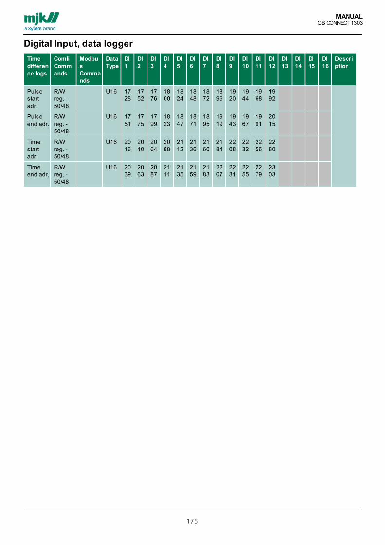
MANUALGB CONNECT 1303
175
Digital Input, data loggerTimedifference logs
ComliCommands
ModbusCommands
DataType
DI1
DI2
DI3
DI4
DI5
DI6
DI7
DI8
DI9
DI10
DI11
DI12
DI13
DI14
DI15
DI16
Description
Pulsestartadr.
R/Wreg. -50/48
U16 1728
1752
1776
1800
1824
1848
1872
1896
1920
1944
1968
1992
Pulseend adr.
R/Wreg. -50/48
U16 1751
1775
1799
1823
1847
1871
1895
1919
1943
1967
1991
2015
Timestartadr.
R/Wreg. -50/48
U16 2016
2040
2064
2088
2112
2136
2160
2184
2208
2232
2256
2280
Timeend adr.
R/Wreg. -50/48
U16 2039
2063
2087
2111
2135
2159
2183
2207
2231
2255
2279
2303
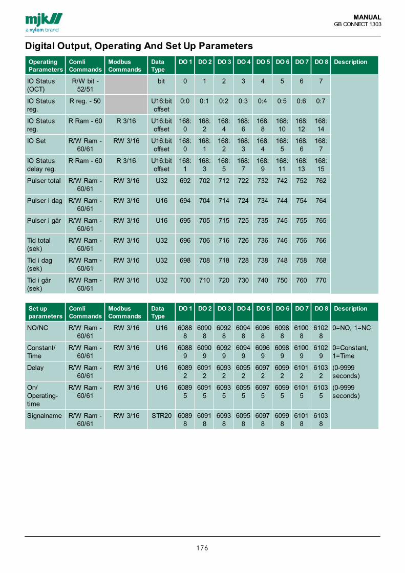
MANUALGB CONNECT 1303
176
Digital Output, Operating And Set Up ParametersOperatingParameters
ComliCommands
ModbusCommands
DataType
DO 1 DO 2 DO 3 DO 4 DO 5 DO 6 DO 7 DO 8 Description
IO Status(OCT)
R/W bit -52/51
bit 0 1 2 3 4 5 6 7
IO Statusreg.
R reg. - 50 U16:bitoffset
0:0 0:1 0:2 0:3 0:4 0:5 0:6 0:7
IO Statusreg.
R Ram - 60 R 3/16 U16:bitoffset
168:0
168:2
168:4
168:6
168:8
168:10
168:12
168:14
IO Set R/W Ram -60/61
RW 3/16 U16:bitoffset
168:0
168:1
168:2
168:3
168:4
168:5
168:6
168:7
IO Statusdelay reg.
R Ram - 60 R 3/16 U16:bitoffset
168:1
168:3
168:5
168:7
168:9
168:11
168:13
168:15
Pulser total
R/W Ram -60/61
RW 3/16 U32 692 702 712 722 732 742 752 762
Pulser i dag R/W Ram -60/61
RW 3/16 U16 694 704 714 724 734 744 754 764
Pulser i går R/W Ram -60/61
RW 3/16 U16 695 705 715 725 735 745 755 765
Tid total(sek)
R/W Ram -60/61
RW 3/16 U32 696 706 716 726 736 746 756 766
Tid i dag(sek)
R/W Ram -60/61
RW 3/16 U32 698 708 718 728 738 748 758 768
Tid i går(sek)
R/W Ram -60/61
RW 3/16 U32 700 710 720 730 740 750 760 770
Set upparameters
ComliCommands
ModbusCommands
DataType
DO 1 DO 2 DO 3 DO 4 DO 5 DO 6 DO 7 DO 8 Description
NO/NC R/W Ram -60/61
RW 3/16 U16 60888
60908
60928
60948
60968
60988
61008
61028
0=NO, 1=NC
Constant/Time
R/W Ram -60/61
RW 3/16 U16 60889
60909
60929
60949
60969
60989
61009
61029
0=Constant,1=Time
Delay R/W Ram -60/61
RW 3/16 U16 60892
60912
60932
60952
60972
60992
61012
61032
(0-9999seconds)
On/Operating-time
R/W Ram -60/61
RW 3/16 U16 60895
60915
60935
60955
60975
60995
61015
61035
(0-9999seconds)
Signalname R/W Ram -60/61
RW 3/16 STR20 60898
60918
60938
60958
60978
60998
61018
61038

MANUALGB CONNECT 1303
177
Analogue Input, Operating And Set Up ParametersOperatingParameters
ComliCommands
ModbusCommands
DataType
AI 1 AI 2 AI3
AI 4 AI 5 AI 6 Description
Status High Limit R bit - 52 bit 50 51 52 53 0=off, 1=on
Status High Limitreg.
R reg. - 50 U16:bitoffset
5:0 5:1 5:2 5:3 0=off, 1=on
Status High Limitreg.
R Ram - 60 R 3/16 U16:bitoffset
180:0
180:2
180:4
180:6
180:8
180:10
0=off, 1=on
Status High Limitdelay reg.
R Ram - 60 R 3/16 U16:bitoffset
180:1
180:3
180:5
180:7
180:9
180:11
0=No, 1=going on
Alarm High Limit R/W bit -52/51
bit 60 61 62 63 0=off, 1=on
Alarm High Limit reg. R reg. - 50 U16:bitoffset
6:0 6:1 6:2 6:3 0=off, 1=on
Alarm High Limit reg. R Ram - 60 R 3/16 U16:bitoffset
182:0
182:2
182:4
182:6
182:8
182:10
0=off, 1=on
Status Low Limit R bit - 52 bit 54 55 56 57 0=off, 1=on
Alarm Low Limit R/W bit -52/51
bit 64 65 66 67 0=off, 1=on
Status Low Limitreg.
R Ram - 60 R 3/16 U16:bitoffset
184:0
184:2
184:4
184:6
184:08
184:10
0=off, 1=on
Status Low Limitdelay reg.
R Ram - 60 R 3/16 U16:bitoffset
184:1
184:3
184:5
184:7
184:9
184:11
0=No, 1=going on
Alarm Low Limit R/W bit -52/51
bit 64 65 66 67 0=off, 1=on
Alarm Low Limit reg. R reg. - 50 U16:bitoffset
6:4 6:5 6:6 6:7 0=off, 1=on
Alarm Low Limit reg. R Ram - 60 R 3/16 U16:bitoffset
186:0
186:2
186:4
186:6
186:8
186:10
0=off, 1=on
Scaled value R reg. - 50 U16 16 17 18 19 21 15
Scaled value R Ram - 60 R 3/16 F32 264 268 272 276 280 284
High Limit pulse total R/W reg. -50/48
U16 80 81 82 83
High Limit pulsetoday
R/W reg. -50/48
U16 160 161 162 163
High Limit pulseyesterday
R/W reg. -50/48
U16 240 241 242 243
High Limit time total(hours)
R/W reg. -50/48
U16 88 89 90 91
High Limit timetoday (minutes)
R/W reg. -50/48
U16 168 169 170 171
High Limit timeyesterday (minutes)
R/W reg. -50/48
U16 248 249 250 251
High Limit pulse total R/W Ram -60/61
RW 3/16 U32 1332
1351
1370
1389
1408
1427
High Limit pulse R/W Ram - RW 3/16 U16 133 135 137 139 141 142
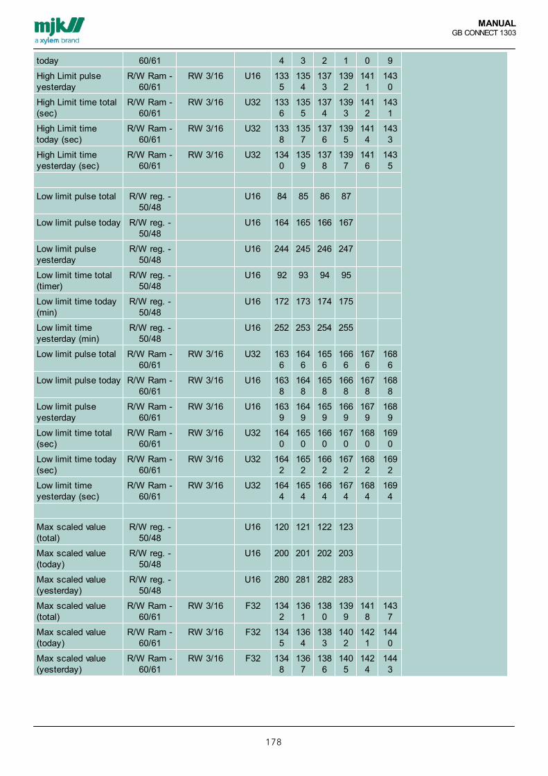
MANUALGB CONNECT 1303
178
today 60/61 4 3 2 1 0 9
High Limit pulseyesterday
R/W Ram -60/61
RW 3/16 U16 1335
1354
1373
1392
1411
1430
High Limit time total(sec)
R/W Ram -60/61
RW 3/16 U32 1336
1355
1374
1393
1412
1431
High Limit timetoday (sec)
R/W Ram -60/61
RW 3/16 U32 1338
1357
1376
1395
1414
1433
High Limit timeyesterday (sec)
R/W Ram -60/61
RW 3/16 U32 1340
1359
1378
1397
1416
1435
Low limit pulse total R/W reg. -50/48
U16 84 85 86 87
Low limit pulse today R/W reg. -50/48
U16 164 165 166 167
Low limit pulseyesterday
R/W reg. -50/48
U16 244 245 246 247
Low limit time total(timer)
R/W reg. -50/48
U16 92 93 94 95
Low limit time today(min)
R/W reg. -50/48
U16 172 173 174 175
Low limit timeyesterday (min)
R/W reg. -50/48
U16 252 253 254 255
Low limit pulse total R/W Ram -60/61
RW 3/16 U32 1636
1646
1656
1666
1676
1686
Low limit pulse today R/W Ram -60/61
RW 3/16 U16 1638
1648
1658
1668
1678
1688
Low limit pulseyesterday
R/W Ram -60/61
RW 3/16 U16 1639
1649
1659
1669
1679
1689
Low limit time total(sec)
R/W Ram -60/61
RW 3/16 U32 1640
1650
1660
1670
1680
1690
Low limit time today(sec)
R/W Ram -60/61
RW 3/16 U32 1642
1652
1662
1672
1682
1692
Low limit timeyesterday (sec)
R/W Ram -60/61
RW 3/16 U32 1644
1654
1664
1674
1684
1694
Max scaled value (total)
R/W reg. -50/48
U16 120 121 122 123
Max scaled value (today)
R/W reg. -50/48
U16 200 201 202 203
Max scaled value (yesterday)
R/W reg. -50/48
U16 280 281 282 283
Max scaled value (total)
R/W Ram -60/61
RW 3/16 F32 1342
1361
1380
1399
1418
1437
Max scaled value (today)
R/W Ram -60/61
RW 3/16 F32 1345
1364
1383
1402
1421
1440
Max scaled value (yesterday)
R/W Ram -60/61
RW 3/16 F32 1348
1367
1386
1405
1424
1443

MANUALGB CONNECT 1303
179
Set up parameters ComliCommands
ModbusCommands
DataType
AI 1 AI 2 AI3
AI 4 AI 5 AI 6 Description
4 mA scaling R/W Ram -60/61
RW 3/16 F32 59002
59090
59178
59266
59354
59442
20 mA scaling R/W Ram -60/61
RW 3/16 F32 59008
59096
59184
59272
59360
59448
Low Limit R/W Ram -60/61
RW 3/16 F32 59017
59105
59193
59281
59369
59457
High Limit R/W Ram -60/61
RW 3/16 F32 59023
59111
59199
59287
59375
59463
Average R/W Ram -60/61
RW 3/16 U16 59029
59117
59205
59293
59381
59469
(0-60 seconds)
High Limit in Use R/W Ram -60/61
RW 3/16 U16 59032
59120
59208
59296
59384
59472
0=No, 1=Yes
High Limit R/W Ram -60/61
RW 3/16 F32 59033
59121
59209
59297
59385
59473
High Limit Delay R/W Ram -60/61
RW 3/16 U16 59039
59127
59215
59303
59391
59479
(0-64800 seconds)
Call on High Limit R/W Ram -60/61
RW 3/16 U16 59042
59130
59218
59306
59394
59482
0=No, 1=Yes
Low Limit in use R/W Ram -60/61
RW 3/16 U16 59043
59131
59219
59307
59395
59483
0=No, 1=Yes
Low Limit alarm R/W Ram -60/61
RW 3/16 F32 59044
59132
59220
59308
59396
59484
Low Limit alarmdelay
R/W Ram -60/61
RW 3/16 F16 59050
59138
59226
59314
59402
59490
(0-64800 seconds)
Call on Low Limitalarm
R/W Ram -60/61
RW 3/16 U16 59053
59141
59229
59317
59405
59493
0=No, 1=Yes
Signal name for AI R/W Ram -60/61
RW 3/16 STR20 59058
59146
59234
59322
59410
59498
Signal name for HighLimit alarm
R/W Ram -60/61
RW 3/16 STR20 59068
59156
59244
59332
59420
59508
Signal name for LowLimit alarm
R/W Ram -60/61
RW 3/16 STR20 59078
59166
59254
59342
59430
59518

MANUALGB CONNECT 1303
180
Analogue Input, Data Logger5 Min. logs Comli
CommandsModbusCommands
DataType
AI 1 AI 2 AI3
AI 4 AI 5 AI 6 Description
5 min. log start adr.scaled value
R/W reg. -50/48
U16 288 576 864 1152
1440
5 min. log slut adr.scaled value
R/W reg. -50/48
U16 575 863 1151
1439
1727
5 min. log start adr.scaled value
R Datalog -75
U16 1000
1288
1576
1864
2152
2440
5 min. log slut adr.scaled value
R Datalog -75
U16 1287
1575
1863
2151
2439
2727
Extended log ComliCommands
ModbusCommands
DataType
AI 1 AI 2 AI3
AI 4 AI 5 AI 6 Description
Extended log startadr.scaled value
R/W reg. -50/48
U16 13312
17408
21504
25600
29696
33792
(for IGSS)
Extended log Endadr.scaled value
R/W reg. -50/48
U16 16191
20287
24383
28479
32575
36671
(for IGSS)
Time Difference logs ComliCommands
ModbusCommands
DataType
AI 1 AI 2 AI3
AI 4 AI 5 AI 6 Description
Pulse High Limitstart adr.
R/W reg. -50/48
U16 2304
2328
2352
2376
Pulse High Limit slutadr.
R/W reg. -50/48
U16 2327
2351
2375
2399
Time High Limit startadr.
R/W reg. -50/48
U16 2496
2520
2544
2568
Time High Limit slutadr.
R/W reg. -50/48
U16 2519
2543
2567
2591
Pulse Low Limit startadr.
R/W reg. -50/48
U16 2400
2424
2448
2472
Pulse Low Limit endadr.
R/W reg. -50/48
U16 2423
2447
2471
2495
Time Low Limit startadr.
R/W reg. -50/48
U16 2592
2616
2640
2664
Time Low Limit endadr.
R/W reg. -50/48
U16 2615
2639
2663
2687

MANUALGB CONNECT 1303
181
Analogue Output, Operating and Set Up ParametersOperatingparameters
Comli Commandos Modbus Commandos Modbus Commandos AO 1 Description
AO set point R/W Ram - 60/61 RW 3/16 F32 628
Set up parameters Comli Commandos Modbus Commandos Modbus Commandos AO 1 Description
4 mA scaling R/W Ram - 60/61 RW 3/16 F32 61530
20 mA scaling R/W Ram - 60/61 RW 3/16 F32 61536
Low Limit R/W Ram - 60/61 RW 3/16 F32 61545
High Limit R/W Ram - 60/61 RW 3/16 F32 61551
Signal name R/W Ram - 60/61 RW 3/16 STR20 61560

MANUALGB CONNECT 1303
182
Internal Flag, Operating and Set Up ParametersDriftparameters
ComliCommandos
ModbusCommandos
DataType
IF1
IF2
IF3
IF4
IF5
IF6
IF7
IF8
IF9
IF10
IF11
IF12
IF13
IF14
IF15
IF16
Description
IO Status(OCT)
R bit - 52 bit 130
131
132
133
134
135
136
137
IO Alarm(OCT)
R/W bit -52/51
bit 140
141
142
143
144
145
146
147
IO Statusreg.
R Ram -60
R 3/16 U16:bit
offset
188:0
188:2
188:4
188:6
188:8
188:10
188:12
188:14
189:0
189:2
189:4
189:6
189:8
189:10
189:12
189:14
IO Alarmreg.
R/WRam -60/61
R/W 3/16 U16:bit
offset
190:0
190:2
190:4
190:6
190:8
190:10
190:12
190:14
191:0
191:2
191:4
191:6
191:8
191:10
191:12
191:14
Pulsestotal
R/WRam -60/61
RW 3/16 U32 1796
1806
1816
1826
1836
1846
1856
1866
1876
1886
1896
1906
1916
1926
1936
1946
PulsesTotal
R/WRam -60/61
RW 3/16 U16 1798
1808
1818
1828
1838
1848
1858
1868
1878
1888
1898
1908
1918
1928
1938
1948
PulsesYesterday
R/WRam -60/61
RW 3/16 U16 1799
1809
1819
1829
1839
1849
1859
1869
1879
1889
1899
1909
1919
1929
1939
1949
Timetotal(secs.)
R/WRam -60/61
RW 3/16 U32 1800
1810
1820
1830
1840
1850
1860
1870
1880
1890
1900
1910
1920
1930
1940
1950
Timetoday(secs.)
R/WRam -60/61
RW 3/16 U32 1802
1812
1822
1832
1842
1852
1862
1872
1882
1892
1902
1912
1922
1932
1942
1952
TimeYesterday (secs.)
R/WRam -60/61
RW 3/16 U32 1804
1814
1824
1834
1844
1854
1864
1874
1884
1894
1904
1914
1924
1934
1944
1954
Set upparameters
ComliCommandos
ModbusCommandos
DataType
IF1
IF2
IF3
IF4
IF5
IF6
IF7
IF8
IF9
IF10
IF11
IF12
IF13
IF14
IF15
IF16
Description
OutputType
R/WRam -60/61
RW 3/16 U16 63498
63543
63588
63633
63678
63723
63768
63813
63858
63903
63948
63993
64038
64083
64128
64173
0=Not InUse,1=DO,2=IF
Outputno.
R/WRam -60/61
RW 3/16 U16 63499
63544
63589
63634
63679
63724
63769
63814
63859
63904
63949
63994
64039
64084
64129
64174
DO=1-8,IF=1-16
Function R/WRam -60/61
RW 3/16 U16 63502
63547
63592
63637
63682
63727
63772
63817
63862
63907
63952
63997
64042
64087
64132
64177

MANUALGB CONNECT 1303
183
0=AND, 1=NAND, 2=OR, 3=NOR, 4=Set/reset, 5=Preset cnt, 6=time, 7=Reset cnt, 8= Integrator
Operand1 type
R/WRam -60/61
RW 3/16 U16 63503
63548
63593
63638
63683
63728
63773
63818
63863
63908
63953
63998
64043
64088
64133
64178
NOT USED = 0, DI = 1, DO = 2, AI_HIGH = 3, AI_LOW = 4, INTERNAL_FLAG = 5, DI_PULSES = 6, DI_TIME = 7,DO_PULSES = 8, DO_TIME = 9, AI_VALUE = 10, AI_HIGH_PULSES = 11, AI_HIGH_TIME = 12, AI_LOW_PULSES= 13, AI_LOW_TIME = 14, INTERNAL_FLAG_PULSES = 15, INTERNAL_FLAG_TIME = 16, AO_VALUE = 17,INSTRUMENTNET_PROCESS_VALUE = 18, AUTO_RESET=19, VAI_HIGH = 20, VAI_LOW = 21, VAI_VALUE =22, VAI_HIGH_PULSES = 23, VAI_HIGH_TIME = 24, VAI_LOW_PULSES = 25, VAI_LOW_TIME = 26,TYPE_OTHER = 27, KONTROLORD = 28.
Operand1 no
R/WRam -60/61
RW 3/16 U16 63504
63549
63594
63639
63684
63729
63774
63819
63864
63909
63954
63999
64044
64089
64134
64179
DI=1-16,DO=1-8,AIH=1-6,AIL=1-6,IF=1-16
Operand2 type
R/WRam -60/61
RW 3/16 U16 63507
63552
63597
63642
63687
63732
63777
63822
63867
63912
63957
64002
64047
64092
64137
64182
NOT USED = 0, DI = 1, DO = 2, AI_HIGH = 3, AI_LOW = 4, INTERNAL_FLAG = 5, DI_PULSES = 6, DI_TIME = 7,DO_PULSES = 8, DO_TIME = 9, AI_VALUE = 10, AI_HIGH_PULSES = 11, AI_HIGH_TIME = 12, AI_LOW_PULSES= 13, AI_LOW_TIME = 14, INTERNAL_FLAG_PULSES = 15, INTERNAL_FLAG_TIME = 16, AO_VALUE = 17,INSTRUMENTNET_PROCESS_VALUE = 18, AUTO_RESET=19, VAI_HIGH = 20, VAI_LOW = 21, VAI_VALUE =22, VAI_HIGH_PULSES = 23, VAI_HIGH_TIME = 24, VAI_LOW_PULSES = 25, VAI_LOW_TIME = 26,TYPE_OTHER = 27, KONTROLORD = 28.
Operand2 nr
R/WRam -60/61
RW 3/16 U16 63508
63553
63598
63643
63688
63733
63778
63823
63868
63913
63958
64003
64048
64093
64138
64183
DI=1-16, DO=1-8, AIH=1-6, AIL=1-6, IF=1-16
Delay R/WRam -60/61
RW 3/16 U16 63511
63556
63601
63646
63691
63736
63781
63826
63871
63916
63961
64006
64051
64096
64141
64186
(0-64800seconds)
ForvalgstællerValue
R/WRam -60/61
RW 3/16 U16 63514
63559
63604
63649
63694
63739
63784
63829
63874
63919
63964
64009
64054
64099
64144
64189
(0-60000)
Forvalgstæller On-time
R/WRam -60/61
RW 3/16 U16 63517
63562
63607
63652
63697
63742
63787
63832
63877
63922
63967
64012
64057
64102
64147
64192
(0-64800seconds)
Starttime(sec.)
R/WRam -60/61
RW 3/16 U32 63520
63565
63610
63655
63700
63745
63790
63835
63880
63925
63970
64015
64060
64105
64150
64195
(86399seconds)
Stop time(sec.)
R/WRam -60/61
RW 3/16 U32 63526
63571
63616
63661
63706
63751
63796
63841
63886
63931
63976
64021
64066
64111
64156
64201
(86399seconds)

MANUALGB CONNECT 1303
184
AlarmCall
R/WRam -60/61
RW 3/16 U16 63532
63577
63622
63667
63712
63757
63802
63847
63892
63937
63982
64027
64072
64117
64162
64207
0=No,1=Yes
Signalname
R/WRam -60/61
RW 3/16 U16 63533
63578
63623
63668
63713
63758
63803
63848
63893
63938
63983
64028
64073
64118
64163
64208

MANUALGB CONNECT 1303
185
Pump Control 1, Operating And Set Up ParametersOperating parameters Comli
CommandsModbusCommands
DataType
P1 P2 P3 P4 P5 P6 P7 P8 Description
IO status R bit - 52 bit 70 71 72 73 74 75 76 77
Starts Total R/W reg. -50/48
U16 96 97 98 99
Starts today R/W reg. -50/48
U16 176 177 178 179
Starts Yesterday R/W reg. -50/48
U16 256 257 258 259
Total Operating Time R/W reg. -50/48
U16 100 101 102 103
Operating Time Today R/W reg. -50/48
U16 180 181 182 183
Operating TimeYesterday
R/W reg. -50/48
U16 260 261 262 263
Total Pumped Volume R/W reg. -50/48
U16 105 106 107 108
Pumped VolumeToday
R/W reg. -50/48
U16 185 186 187 188
Pumped VolumeYesterday
R/W reg. -50/48
U16 265 266 267 268
Pumping Capacity R/W reg. -50/48
U16 112 113 114 115
Status-Word for Pump R/W reg. -50/48
U16 3048
3049
3050
3051
IO status register R Ram - 60 R 3/16 U16:bitoffset
192:0
192:1
192:2
192:3
192:4
192:5
192:6
192:7
Starts Total R/W Ram -60/61
RW 3/16 U32 344 367 390 413 436 459 482 505
Starts Today R/W Ram -60/61
RW 3/16 U16 346 369 392 415 438 461 484 507
Starts Yesterday R/W Ram -60/61
RW 3/16 U16 347 370 393 416 439 462 485 508
Operating Time Total R/W Ram -60/61
RW 3/16 U32 348 371 394 417 440 463 486 509
Operating Time Today R/W Ram -60/61
RW 3/16 U32 350 373 396 419 442 465 488 511
Operating TimeYesterday
R/W Ram -60/61
RW 3/16 U32 352 375 398 421 444 467 490 513
Pumped Volume Total R/W Ram -60/61
RW 3/16 F32 354 377 400 423 446 469 492 515
Pumped VolumeToday
R/W Ram -60/61
RW 3/16 F32 358 381 404 427 450 473 496 519
Pumped VolumeYesterday
R/W Ram -60/61
RW 3/16 F32 360 383 406 429 452 475 498 521
Pumped Volume Totalsum
R/W Ram -60/61
RW 3/16 F32 528
Pumped Volume sumToday
R/W Ram -60/61
RW 3/16 F32 532

MANUALGB CONNECT 1303
186
Pumped Volume sumYesterday
R/W Ram -60/61
RW 3/16 F32 534
Current flow R/W Ram -60/61
RW 3/16 F32 536
Pump Capacity R/W Ram -60/61
RW 3/16 F32 362 385 408 431 454 477 500 523
Control Word for pump R/W Ram -60/61
RW 3/16 U16 366 389 412 435 458 481 504 527
Status register forControl Word
R Ram - 60 R 3/16 U16:bitoffset
167:0
167:1
167:2
167:3
167:4
167:5
167:6
167:7
Forced Start of pump R/W Ram -60/61
RW 3/16 U16 140 143 146 149 152 155 158 161
Forced stop of pump R/W Ram -60/61
RW 3/16 U16 141 144 147 150 153 156 159 162
Block Pump R/W Ram -60/61
RW 3/16 U16 142 145 148 151 154 157 160 163
Set up parameters ComliCommands
ModbusCommands
Datatype
P1 P2 P3 P4 P5 P6 P7 P8 Description
Pump Control In Use/Not In Use
R/W Ram -60/61
RW 3/16 U16 62505
0=No, 1=Yes
Pump Controlmaximum pumps
R/W Ram -60/61
RW 3/16 U16
DO for Pumps R/W Ram -60/61
RW 3/16 U16 62241
62274
62307
62340
62373
62406
62439
62472
Alternation in Use R/W Ram -60/61
RW 3/16 U16 62244
62277
62310
62343
62376
62409
62442
62475
0=No, 1=Yes
Start Level R/W reg. -50/48
U16 24 25 26 27
Stop Level R/W reg. -50/48
U16 28 29 30 31
Start Level R/W Ram -60/61
RW 3/16 F32 62245
62278
62311
62344
62377
62410
62443
62476
Stop Level R/W Ram -60/61
RW 3/16 F32 62251
62284
62317
62350
62383
62416
62449
62482
Delay R/W Ram -60/61
RW 3/16 F16 62257
62290
62323
62356
62389
62422
62455
62488

MANUALGB CONNECT 1303
187
Control Wordparameters
ComliCommands
ModbusCommands
Datatype
P1 P2 P3 P4 P5 P6 P7 P8 Description
Control Word In Use/Not in Use
R/W Ram -60/61
RW 3/16 U16 56001
Control Word re-entries
R/W Ram -60/61
RW 3/16 U16 56000
Operating signal type R/W Ram -60/61
RW 3/16 U16 56005
56041
56077
56113
56149
56185
56221
56257
Operation Sign no. R/W Ram -60/61
RW 3/16 U16 56006
56042
56078
56114
56150
56186
56222
56258
Operation Signal Delay R/W Ram -60/61
RW 3/16 U16 56007
56043
56079
56115
56151
56187
56223
56259
Amount of Alarm-indicators
R/W Ram -60/61
RW 3/16 U16 56002
56038
56074
56110
56146
56182
56218
56254
Alarm indicator 1signal type
R/W Ram -60/61
RW 3/16 U16 56010
56046
56082
56118
56154
56190
56226
56262
Alarm indicator 1signal no.
R/W Ram -60/61
RW 3/16 U16 56011
56047
56083
56119
56155
56191
56227
56263
Alarm indicator 2signal type
R/W Ram -60/61
RW 3/16 U16 56012
56048
56084
56120
56156
56192
56228
56264
Alarm indicator 2signal no.
R/W Ram -60/61
RW 3/16 U16 56013
56049
56085
56121
56157
56193
56229
56265
Alarm indicator 3signal type
R/W Ram -60/61
RW 3/16 U16 56014
56050
56086
56122
56158
56194
56230
56266
Alarm indicator 3signal no.
R/W Ram -60/61
RW 3/16 U16 56015
56051
56087
56123
56159
56195
56231
56267
Alarm indicator 4signal type
R/W Ram -60/61
RW 3/16 U16 56016
56052
56088
56124
56160
56196
56232
56268
Alarm indicator 4signal no.
R/W Ram -60/61
RW 3/16 U16 56017
56053
56089
56125
56161
56197
56233
56269
Alarm indicator 5signal type
R/W Ram -60/61
RW 3/16 U16 56018
56054
56090
56126
56162
56198
56234
56270
Alarm indicator 5signal no.
R/W Ram -60/61
RW 3/16 U16 56019
56055
56091
56127
56163
56199
56235
56271
Alarm indicator 6signal type
R/W Ram -60/61
RW 3/16 U16 56020
56056
56092
56128
56164
56200
56236
56272
Alarm indicator 6signal no.
R/W Ram -60/61
RW 3/16 U16 56021
56057
56093
56129
56165
56201
56237
56273
Alarm indicator 7signal type
R/W Ram -60/61
RW 3/16 U16 56022
56058
56094
56130
56166
56202
56238
56274
Alarm indicator 7signal no.
R/W Ram -60/61
RW 3/16 U16 56023
56059
56095
56131
56167
56203
56239
56275
Alarm indicator 8signal type
R/W Ram -60/61
RW 3/16 U16 56024
56060
56096
56132
56168
56204
56240
56276
Alarm indicator 8signal no.
R/W Ram -60/61
RW 3/16 U16 56025
56061
56097
56133
56169
56205
56241
56277
Alarm indicator 9signal type
R/W Ram -60/61
RW 3/16 U16 56026
56062
56098
56134
56170
56206
56242
56278
Alarm indicator 9signal no.
R/W Ram -60/61
RW 3/16 U16 56027
56063
56099
56135
56171
56207
56243
56279
Alarm indicator 10signal type
R/W Ram -60/61
RW 3/16 U16 56028
56064
56100
56136
56172
56208
56244
56280
Alarm indicator 10signal no.
R/W Ram -60/61
RW 3/16 U16 56029
56065
56101
56137
56173
56209
56245
56281
Digital Output for resetsignal
R/W Ram -60/61
RW 3/16 U16 56031
56067
56103
56139
56175
56211
56247
56283
Digital Input for reset ofControl Word
R/W Ram -60/61
RW 3/16 U16 56033
56069
56105
56141
56177
56213
56249
56285
Alarm Call Yes/No R/W Ram -60/61
RW 3/16 U16 56034
56070
56106
56142
56178
56214
56250
56286

MANUALGB CONNECT 1303
188
Set point displacementset up
ComliCommands
ModbusCommands
Datatype
P1 P2 P3 P4 P5 P6 P7 P8 Description
Set PointDisplacement in Use
R/W Ram -60/61
RW 3/16 U16 57502
0=No, 1=Yes
Activate Set PointDisplacement
R/W Ram -60/61
RW 3/16 U16 57501
0=No, 1=Yes
Set PointDisplacement (offsetcm)
R/W Ram -60/61
RW 3/16 F32 57503
Duration (minutes) R/W Ram -60/61
RW 3/16 U16 57509
"Displacement onTime" In Use
R/W Ram -60/61
RW 3/16 U16 57512
0=No, 1=Yes
Start Time R/W Ram -60/61
RW 3/16 U32 57513
Stop time R/W Ram -60/61
RW 3/16 U32 57519
Depth Pumping set up ComliCommands
ModbusCommands
Datatype
P1 P2 P3 P4 P5 P6 P7 P8 Description
Depth Pumping In Use R/W Ram -60/61
RW 3/16 U16 57525
0=No, 1=Yes
Pump for DepthPumping
R/W Ram -60/61
RW 3/16 U16 57526
Starts between DepthPumping
R/W Ram -60/61
RW 3/16 U16 57527
(0-9999)
Time between DepthPumping
R/W Ram -60/61
RW 3/16 U16 57530
(0-999)
Time between DepthPumping in Use
R/W Ram -60/61
RW 3/16 U32 57533
Duration of depthPumping (sec)
R/W Ram -60/61
RW 3/16 U32 57540
(0-300 sec)
Depthpumping time R/W Ram -60/61
RW 3/16 U32 57534
Flow calculation set up ComliCommands
ModbusCommands
Datatype
P1 P2 P3 P4 P5 P6 P7 P8 Description
Calculation in use R/W Ram -60/61
RW 3/16 U16 57546
0=No, 1=Yes
Start Level for Volume R/W Ram -60/61
RW 3/16 U32 57549
Stop Level for Volume R/W Ram -60/61
RW 3/16 U32 57555
Volume Size R/W Ram -60/61
RW 3/16 U32 57561

MANUALGB CONNECT 1303
189
Pump Control 2, Operating And Set Up ParametersDriftparameters
Comlicommandos
Modbuscommandos
Datatype
P1 P2 P3 P4 P5 P6 P7 P8 Description
Status R/W Ram -60/61
RW 3/16 U16 550 561 572 583 594 605 616 627 0=stopped,1=Operating
Starts Total R/W Ram -60/61
RW 3/16 U32 540 551 562 573 584 595 606 617
Starts Today R/W Ram -60/61
RW 3/16 U16 542 553 564 575 586 597 608 619
StarterYesterday
R/W Ram -60/61
RW 3/16 U16 543 554 565 576 587 598 609 620
Operatingtime Total
R/W Ram -60/61
RW 3/16 U32 544 555 566 577 588 599 610 621
Operatingtime Today
R/W Ram -60/61
RW 3/16 U32 546 557 568 579 590 601 612 623
OperatingtimeYesterday
R/W Ram -60/61
RW 3/16 U32 548 559 570 581 592 603 614 625
Set upparameters
Comlicommandos
Modbuscommandos
Datatype
P1 P2 P3 P4 P5 P6 P7 P8 Description
DO for Pump R/W Ram -60/61
RW 3/16 U16 62638
62671
62704
62737
62770
62803
62836
62869
Alternation inuse
R/W Ram -60/61
RW 3/16 U16 62641
62674
62707
62740
62773
62806
62839
62872
0=No, 1=Yes
Start Level R/W Ram -60/61
RW 3/16 F32 62642
62675
62708
62741
62774
62807
62840
62873
Stop Level R/W Ram -60/61
RW 3/16 F32 62648
62681
62714
62747
62780
62813
62846
62879
Amount ofpumps
R/W Ram -60/61
RW 3/16 U16 62587
(1-8)
No ofsimultaneously runningpumps
R/W Ram -60/61
RW 3/16 U16 62590
(1-8)
AI for Level R/W Ram -60/61
RW 3/16 U16 62593

MANUALGB CONNECT 1303
190
Energy Optimized Pump Control, Operating And Set Up ParametersDrift parameters Comli
commandos
Modbuscommandos
Datatype
P1 P2 P3 P4 P5 P6 P7 P8 Description
Reference R/W Ram -60/61
RW 3/16 U16 3000
3019
3038
3057
3076
3095
3114
3133
0=0.00%,10000=100.00%
Effect R Ram - 60 R 3/16 U32 3001
3020
3039
3058
3077
3096
3115
3134
Voltage R Ram - 60 R 3/16 U16 3003
3022
3041
3060
3079
3098
3117
3136
(0-1000 VAC)
Frequency R Ram - 60 R 3/16 U16 3004
3023
3042
3061
3080
3099
3118
3137
0-100 Hz
Current R Ram - 60 R 3/16 U32 3005
3024
3043
3062
3081
3100
3119
3138
0.00-1000000.00A
Alarm-Word R Ram - 60 R 3/16 U16 3007
3026
3045
3064
3083
3102
3121
3140
Total number of starts R Ram - 60 R 3/16 U32 3008
3027
3046
3065
3084
3103
3122
3141
DC-voltage R Ram - 60 R 3/16 U16 3014
3033
3052
3071
3090
3109
3128
3147
(0-1000 VDC)
Total Operating Time R Ram - 60 R 3/16 U32 3015
3034
3053
3072
3091
3110
3129
3148
kWh-counter R Ram - 60 R 3/16 U32 3017
3036
3055
3074
3093
3112
3131
3150
(0-99999999kWh)
Status-word for pump R/W Ram -60/61
RW 3/16 U16 3161
3162
3163
3164
3165
3166
3167
3168
Energ Saving % R Ram - 60 R 3/16 F32 3156
(0-100 %)
Flow dataparameters
Comlicommandos
Modbuscommandos
Datatype
P1 P2 P3 P4 P5 P6 P7 P8 Description
Flow R Ram - 60 R 3/16 F32 2000
Pumped VolumeTotal
R Ram - 60 R 3/16 F32 2014
Set up parameters Comlicommandos
Modbuscommandos
Datatype
P1 P2 P3 P4 P5 P6 P7 P8 Description
Energy optimizedpump control : Inuse / not in use
R/W Ram -60/61
RW 3/16 U16 29 0=No, 1=Yes
Ramp up time R/W Ram -60/61
RW 3/16 U32 3010
3029
3048
3067
3086
3105
3124
3143
(0.00-999999.00seconds)
Ramp down time R/W Ram -60/61
RW 3/16 U32 3012
3031
3050
3069
3088
3107
3126
3145
(0.00-999999.00seconds)
Optimizing frequency R/W Ram -60/61
RW 3/16 U16 50121
50182
50243
50304
50365
50426
50487
50548
(0-50 Hz)

MANUALGB CONNECT 1303
191
Maximum frequency R/W Ram -60/61
RW 3/16 U16 50124
50185
50246
50307
50368
50429
50490
50551
(0-50 Hz)
Minimum frequency R/W Ram -60/61
RW 3/16 U16 50127
50188
50249
50310
50371
50432
50493
50554
(0-50 Hz)
AI for Level R/W Ram -60/61
RW 3/16 U16 50003
(1-6)
Number of pumps R/W Ram -60/61
RW 3/16 U16 50000
(1-8)
Frequencytransformer type
R/W Ram -60/61
RW 3/16 U16 50006
0=VLT 1=I/O
Frequencytransformer alarmYes/No
R/W Ram -60/61
RW 3/16 U16 50013
Frequencytransformer alarmdelay
R/W Ram -60/61
RW 3/16 U32 50007
Frequencytransformer alarmname
R/W Ram -60/61
RW 3/16 STR20
50014
Flowmeter type R/W Ram -60/61
RW 3/16 U16 50031
0=MagFlux 1=AI
Flowmeter AI number R/W Ram -60/61
RW 3/16 U16 50032
Flowmeter alarmYes/No
R/W Ram -60/61
RW 3/16 U16 50039
Flowmeter alarmdelay
R/W Ram -60/61
RW 3/16 U16 50033
Flowmeter alarmname
R/W Ram -60/61
RW 3/16 STR20
50040
Maximum Level R/W Ram -60/61
RW 3/16 F32 50068
Start pump Level R/W Ram -60/61
RW 3/16 F32 50050
Optimizing Level R/W Ram -60/61
RW 3/16 F32 50062
Minimum Level R/W Ram -60/61
RW 3/16 F32 50074
Stop Level R/W Ram -60/61
RW 3/16 F32 50056
Time for wash-out R/W Ram -60/61
RW 3/16 U32 50080
Duration of wash-out R/W Ram -60/61
RW 3/16 U16 50082
start time (at 50 Hz) R/W Ram -60/61
RW 3/16 U16 50085

MANUALGB CONNECT 1303
192
Maximum flow limit R/W Ram -60/61
RW 3/16 F32 50088
Minimum flow limit R/W Ram -60/61
RW 3/16 F32 50090
Autotuning set up Comlicommandos
Modbuscommandos
Datatype
P1 P2 P3 P4 P5 P6 P7 P8 Description
Autotuning i brug R/W Ram -60/61
RW 3/16 U16 50092
0=No, 1=Yes
Antal timer mellemautotuning
R/W Ram -60/61
RW 3/16 U16 50093
(0- timer)
Depth Pumping setup
Comlicommandos
Modbuscommandos
Datatype
P1 P2 P3 P4 P5 P6 P7 P8 Description
Depth Pumping inuse
R/W Ram -60/61
RW 3/16 U16 50099
0=No, 1=Yes
Pump for DepthPumping
R/W Ram -60/61
RW 3/16 U16 50100
Starts between DepthPumping
R/W Ram -60/61
RW 3/16 U16 50101
Hours between DepthPumping
R/W Ram -60/61
RW 3/16 U16 50104
Time for DepthPumping in use
R/W Ram -60/61
RW 3/16 U16 50107
Time for DepthPumping
R/W Ram -60/61
RW 3/16 U32 50108
Duration of DepthPumping
R/W Ram -60/61
RW 3/16 U32 50114
Control WordParameters
Comlicommandos
Modbuscommandos
Datatype
P1 P2 P3 P4 P5 P6 P7 P8 Description
Control Word in use R/W Ram -60/61
RW 3/16 U16 50120
0=No, 1=Yes
Operating SignalType
R/W Ram -60/61
RW 3/16 U16 50130
50191
50252
50313
50374
50435
50496
50557
Operating Signal no. R/W Ram -60/61
RW 3/16 U16 50131
50192
50253
50314
50375
50436
50497
50558
Operating signalDelay
R/W Ram -60/61
RW 3/16 U16 50132
50193
50254
50315
50376
50437
50498
50559
Number of alarm-indicators
R/W Ram -60/61
RW 3/16 U16 50133
50194
50255
50316
50377
50438
50499
50560
Alarm indicator 1signal type
R/W Ram -60/61
RW 3/16 U16 50134
50195
50256
50317
50378
50439
50500
50561
Alarm indicator 1signal no.
R/W Ram -60/61
RW 3/16 U16 50135
50196
50257
50318
50379
50440
50501
50562
Alarm indicator 2signal type
R/W Ram -60/61
RW 3/16 U16 50136
50197
50258
50319
50380
50441
50502
50563
Alarm indicator 2 R/W Ram - RW 3/16 U16 501 501 502 503 503 504 505 505

MANUALGB CONNECT 1303
193
signal no. 60/61 37 98 59 20 81 42 03 64
Alarm indicator 3signal type
R/W Ram -60/61
RW 3/16 U16 50138
50199
50260
50321
50382
50443
50504
50565
Alarm indicator 3signal no.
R/W Ram -60/61
RW 3/16 U16 50139
50200
50261
50322
50383
50444
50505
50566
Alarm indicator 4signal type
R/W Ram -60/61
RW 3/16 U16 50140
50201
50262
50323
50384
50445
50506
50567
Alarm indicator 4signal no.
R/W Ram -60/61
RW 3/16 U16 50141
50202
50263
50324
50385
50446
50507
50568
Alarm indicator 5signal type
R/W Ram -60/61
RW 3/16 U16 50142
50203
50264
50325
50386
50447
50508
50569
Alarm indicator 5signal no.
R/W Ram -60/61
RW 3/16 U16 50143
50204
50265
50326
50387
50448
50509
50570
Alarm indicator 6signal type
R/W Ram -60/61
RW 3/16 U16 50144
50205
50266
50327
50388
50449
50510
50571
Alarm indicator 6signal no.
R/W Ram -60/61
RW 3/16 U16 50145
50206
50267
50328
50389
50450
50511
50572
Alarm indicator 7signal type
R/W Ram -60/61
RW 3/16 U16 50146
50207
50268
50329
50390
50451
50512
50573
Alarm indicator 7signal no.
R/W Ram -60/61
RW 3/16 U16 50147
50208
50269
50330
50391
50452
50513
50574
Alarm indicator 8signal type
R/W Ram -60/61
RW 3/16 U16 50148
50209
50270
50331
50392
50453
50514
50575
Alarm indicator 8signal no.
R/W Ram -60/61
RW 3/16 U16 50149
50210
50271
50332
50393
50454
50515
50576
Alarm indicator 9signal type
R/W Ram -60/61
RW 3/16 U16 50150
50211
50272
50333
50394
50455
50516
50577
Alarm indicator 9signal no.
R/W Ram -60/61
RW 3/16 U16 50151
50212
50273
50334
50395
50456
50517
50578
Alarm indicator 10signal type
R/W Ram -60/61
RW 3/16 U16 50152
50213
50274
50335
50396
50457
50518
50579
Alarm indicator 10signal no.
R/W Ram -60/61
RW 3/16 U16 50153
50214
50275
50336
50397
50458
50519
50580
Alarm indicator 11signal type
R/W Ram -60/61
RW 3/16 U16 50154
50215
50276
50337
50398
50459
50520
50581
Alarm indicator 11signal no.
R/W Ram -60/61
RW 3/16 U16 50155
50216
50277
50338
50399
50460
50521
50582
Alarm indicator 12signal type
R/W Ram -60/61
RW 3/16 U16 50156
50217
50278
50339
50400
50461
50522
50583
Alarm indicator 12signal no.
R/W Ram -60/61
RW 3/16 U16 50157
50218
50279
50340
50401
50462
50523
50584
DO start/stop signal R/W Ram -60/61
RW 3/16 U16 50163
50224
50285
50346
50407
50468
50529
50590
MAN.-AUTO Switchin use
R/W Ram -60/61
RW 3/16 U16 50165
50226
50287
50348
50409
50470
50531
50592
DI no. for MAN. R/W Ram -60/61
RW 3/16 U16 50166
50227
50288
50349
50410
50471
50532
50593
DI no. for AUTO R/W Ram -60/61
RW 3/16 U16 50169
50230
50291
50352
50413
50474
50535
50596

MANUALGB CONNECT 1303
194
Storm Flow CalculationDrift parameters Comli commandos Modbus commandos Data type Addres
sDescription
Stormflow flow m3/h R/W reg. - 50/48 U16 22
Stormflow volume Total m3 R/W reg. - 50/48 U16 104
Stormflow volume today m3 R/W reg. - 50/48 U16 184
Stormflow volume yesterdaym3
R/W reg. - 50/48 U16 264
Stormflow flow Actual R Ram - 60 R 3/16 F32 328
Stormflow volume Total R/W Ram - 60/61 R/W 3/16 F32 332
Stormflow volume today R/W Ram - 60/61 R/W 3/16 F32 336
Stormflow volume yesterday R/W Ram - 60/61 R/W 3/16 F32 338
Stormflow Level R Ram - 60 R 3/16 F32 340 Niveau for beregning afoverløb, Niveau minus…
Timedif-logs
Stormflow volume m3 startadr.
R/W reg. - 50/48 u16 2880
Stormflow volume m3 stopadr.
R/W reg. - 50/48 u16 2903
Setup parameters Comli commando Modbus commando Data type Address
Stormflow No/Yes R/W Ram - 60/61 R/W 3/16 U16 64218
Stormflow zero signal type R Ram - 60 R 3/16 U16 64221
Stormflow zero signal no R/W Ram - 60/61 R/W 3/16 U16 64224
Stormflow level signal type R/W Ram - 60/61 R/W 3/16 U16 64227
Stormflow level signal no R/W Ram - 60/61 R/W 3/16 U16 64230 AI-RS485
Stomflow no of Q(H) points R/W Ram - 60/61 R/W 3/16 U16 64233
Flow Q Level H
Stormflow Q(H) 1 R/W Ram - 60/61 R/W 3/16 F32 64242 64236
Stormflow Q(H) 2 R/W Ram - 60/61 R/W 3/16 F32 64254 64248
Stormflow Q(H) 3 R/W Ram - 60/61 R/W 3/16 F32 64266 64260
Stormflow Q(H) 4 R/W Ram - 60/61 R/W 3/16 F32 64278 64272
Stormflow Q(H) 5 R/W Ram - 60/61 R/W 3/16 F32 64290 64284
Stormflow Q(H) 6 R/W Ram - 60/61 R/W 3/16 F32 64302 64296
Stormflow Q(H) 7 R/W Ram - 60/61 R/W 3/16 F32 64314 64308
Stormflow Q(H) 8 R/W Ram - 60/61 R/W 3/16 F32 64326 64320
Stormflow Q(H) 9 R/W Ram - 60/61 R/W 3/16 F32 64338 64332
Stormflow Q(H) 10 R/W Ram - 60/61 R/W 3/16 F32 64350 64344

MANUALGB CONNECT 1303
195
Logical Functions
188 IF 8-1 status U16 none ReadOnly
Internal flag 1-16 status
189 IF 16-9 status U16 none ReadOnly
Internal flag 1-16 status
190 IF 8-1 alarm status U16 none Reset/Read
Internal flag 1-16 alarm status
191 IF 16-9 alarm status U16 none Reset/Read
Internal flag 1-16 alarm status
Operating data for internal flag.
1796 IF 1 no of pulses total U32{Low}
1797 U32 {High]
1798 IF 1 no of pulses today U16
1799 IF 1 no of pulses yesterday U16
1800 IF 1 time total U32{Low}
1801 U32 {High]
1802 IF 1 time today U32{Low}
1803 U32 {High]
1804 IF 1 time yesterday U32{Low}
Logic-function (1)
63498
Logical expression 1 Output Signaltype
U16 R/W Logical expression 1
63499
Logical expression 1 Output number U16 R/W
63500
Logical expression 1 Output numberMin
U16 ReadOnly
63501
Logical expression 1 Output numberMax
U16 ReadOnly
63502
Logical expression 1 Operator type U16 R/W
63503
Logical expression 1 Operand 1Signal type
U16 R/W
63504
Logical expression 1 Operand 1number
U16 R/W
63505
Logical expression 1 Operand 1number Min
U16 ReadOnly
63506
Logical expression 1 Operand 1number Max
U16 ReadOnly
63507
Logical expression 1 Operand 2Signal type
U16 R/W
63508
Logical expression 1 Operand 2number
U16 R/W
63509
Logical expression 1 Operand 2number Min
U16 ReadOnly

MANUALGB CONNECT 1303
196
63510
Logical expression 1 Operand 2number Max
U16 ReadOnly
63511
Logical expression 1 Delay U16 R/W
63512
Logical expression 1 Delay Min U16 ReadOnly
63513
Logical expression 1 Delay Max U16 ReadOnly
63514
Logical expression 1 Preset countervalue
U16 R/W
63515
Logical expression 1 Preset countervalue Min
U16 ReadOnly
63516
Logical expression 1 Preset countervalue Max
U16 ReadOnly
63517
Logical expression 1 Preset counterclosed time
U16 R/W
63518
Logical expression 1 Preset counterclosed time Min
U16 ReadOnly
63519
Logical expression 1 Preset counterclosed time Max
U16 ReadOnly
63520
Logical expression 1 Start timeHH:MM
U32{Low}
R/W Seconds from year 2000. Hour and minutes of dayis used
63521
U32{High}
R/W
63522
Logical expression 1 Start timeHH:MM Min
U32{Low}
ReadOnly
63523
U32{High}
ReadOnly
63524
Logical expression 1 Start timeHH:MM Max
U32{Low}
ReadOnly
63525
U32{High}
ReadOnly
63526
Logical expression 1 Stop timeHH:MM
U32{Low}
R/W Seconds from year 2000. Hour and minutes of dayis used
63527
U32{High}
R/W
63528
Logical expression 1 Stop timeHH:MM Min
U32{Low}
ReadOnly
63529
U32{High}
ReadOnly
63530
Logical expression 1 Stop timeHH:MM Max
U32{Low}
ReadOnly
63531
U32{High}
ReadOnly
63532
Logical expression 1 Alarm call on/off U16 R/W
63533
Logical expression 1 Label STR20
R/W

MANUALGB CONNECT 1303
197
Alarm HandlingOperating parameters Comli
commandoModbuscommando
Datatype
address
Control-signal R/W bit -52/51
bit 102 1=alarm for sending
Control-signal R/W Ram -60/61
RW 3/16 U16 43:6 1=alarm for sending
Sign all alarms R/W Ram -60/61
RW 3/16 U16 58336
Alarm parameters Datatype
Alarm 1
Alarm 2
Alarm 3
Alarm 4
Alarm5
Alarm 6
Alarm7
Alarm 8
Alarm text R Ram - 60 R 3/16 STR20
58200
58217
58234
58251
58268
58285
58302
58319
Start Time R Ram - 60 R 3/16 U32 58210
58227
58244
58261
58278
58295
58312
58329
Stop Time R Ram - 60 R 3/16 U32 58212
58229
58246
58263
58280
58297
58314
58331
Alarm signal type R Ram - 60 R 3/16 U16 58214
58231
58248
58265
58282
58299
58316
58333
Alarm signal no. R Ram - 60 R 3/16 U16 58215
58232
58249
58266
58283
58300
58317
58334
Alarm status R/W Ram -60/61
RW 3/16 U16 58216
58233
58250
58267
58284
58301
58318
58335
0=alarm signed for and alarm condition is no longer present, 1=alarm signed for and alarm condition is still present,2=alarm not signed for and alarm condition is no longer present, 3=alarm not signed for and alarm condition is still present
Setup parameters
Datatype
adr.
Automatic AlarmResetting
R/W Ram -60/61
RW 3/16 U16 62902
0=no, 1=yes
Call on automatic alarmreset
R/W Ram -60/61
RW 3/16 U16 62903
0=no, 1=yes
Call on power supplyfailure
R/W Ram -60/61
RW 3/16 U16 62904
0=no, 1=yes
Call on low batteryvoltage
R/W Ram -60/61
RW 3/16 U16 62905
0=no, 1=yes
Connect Phone no.(PSTN)
R/W Ram -60/61
RW 3/16 STR20
62909
SMSC telefonno. R/W Ram -60/61
RW 3/16 STR20
62918

MANUALGB CONNECT 1303
198
Process Value For Connected DevicesModbusaddress
Description Data type
2000 Device 1 PV 1 Value F32
2002 Device 1 PV 1 Unit U16
2003 Device 1 PV 1 Name STR 20
2013 Device 1 PV 1Precision
S16
2014 Device 1 PV 2 Value F32
2016 Device 1 PV 2 Unit U16
2017 Device 1 PV 2 Name STR 20
2027 Device 1 PV 2Precision
S16
2028 Device 1 control signal U16
2029 Device 2 PV 1 Value F32
2031 Device 2 PV 1 Unit U16
2032 Device 2 PV 1 Name STR 20
2042 Device 2 PV 1Precision
S16
2043 Device 2 PV 2 Value F32
2045 Device 2 PV 2 Unit U16
2046 Device 2 PV 2 Name STR 20
2056 Device 2 PV 2Precision
S16
2057 Device 2 control signal U16
2058 Device 3 PV 1 Value F32
2060 Device 3 PV 1 Unit U16
2061 Device 3 PV 1 Name STR 20
2071 Device 3 PV 1Precision
S16
2072 Device 3 PV 2 Value F32
2074 Device 3 PV 2 Unit U16
2075 Device 3 PV 2 Name STR 20
2085 Device 3 PV 2Precision
S16
2086 Device 3 control signal U16
2087 Device 4 PV 1 Value F32
2089 Device 4 PV 1 Unit U16
2090 Device 4 PV 1 Name STR 20
2100 Device 4 PV 1Precision
S16
2101 Device 4 PV 2 Value F32

MANUALGB CONNECT 1303
199
2103 Device 4 PV 2 Unit U16
2104 Device 4 PV 2 Name STR 20
2114 Device 4 PV 2Precision
S16
2115 Device 4 control signal U16
2116 Device 5 PV 1 Value F32
2118 Device 5 PV 1 Unit U16
2119 Device 5 PV 1 Name STR 20
2129 Device 5 PV 1Precision
S16
2130 Device 5 PV 2 Value F32
2132 Device 5 PV 2 Unit U16
2133 Device 5 PV 2 Name STR 20
2143 Device 5 PV 2Precision
S16
2144 Device 5 control signal U16
2145 Device 6 PV 1 Value F32
2147 Device 6 PV 1 Unit U16
2148 Device 6 PV 1 Name STR 20
2158 Device 6 PV 1Precision
S16
2159 Device 6 PV 2 Value F32
2161 Device 6 PV 2 Unit U16
2162 Device 6 PV 2 Name STR 20
2172 Device 6 PV 2Precision
S16
2173 Device 6 control signal U16
2174 Device 7 PV 1 Value F32
2176 Device 7 PV 1 Unit U16
2177 Device 7 PV 1 Name STR 20
2187 Device 7 PV 1Precision
S16
2188 Device 7 PV 2 Value F32
2190 Device 7 PV 2 Unit U16
2191 Device 7 PV 2 Name STR 20
2201 Device 7 PV 2Precision
S16
2202 Device 7 control signal U16
2203 Device 8 PV 1 Value F32
2205 Device 8 PV 1 Unit U16
2206 Device 8 PV 1 Name STR 20
2216 Device 8 PV 1 S16

MANUALGB CONNECT 1303
200
Precision
2217 Device 8 PV 2 Value F32
2219 Device 8 PV 2 Unit U16
2220 Device 8 PV 2 Name STR 20
2230 Device 8 PV 2Precision
S16
2231 Device 8 control signal U16
2232 Device 9 PV 1 Value F32
2234 Device 9 PV 1 Unit U16
2235 Device 9 PV 1 Name STR 20
2245 Device 9 PV 1Precision
S16
2246 Device 9 PV 2 Value F32
2248 Device 9 PV 2 Unit U16
2249 Device 9 PV 2 Name STR 20
2259 Device 9 PV 2Precision
S16
2260 Device 9 control signal U16
2261 Device 10 PV 1 Value F32
2263 Device 10 PV 1 Unit U16
2264 Device 10 PV 1 Name STR 20
2274 Device 10 PV 1Precision
S16
2275 Device 10 PV 2 Value F32
2277 Device 10 PV 2 Unit U16
2278 Device 10 PV 2 Name STR 20
2288 Device 10 PV 2Precision
S16
2289 Device 10 controlsignal
U16
2290 Device 11 PV 1 Value F32
2292 Device 11 PV 1 Unit U16
2293 Device 11 PV 1 Name STR 20
2303 Device 11 PV 1Precision
S16
2304 Device 11 PV 2 Value F32
2306 Device 11 PV 2 Unit U16
2307 Device 11 PV 2 Name STR 20
2317 Device 11 PV 2Precision
S16
2318 Device 11 controlsignal
U16
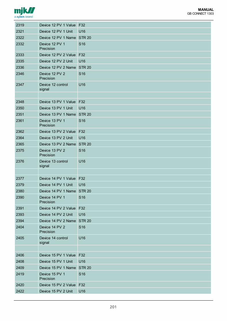
MANUALGB CONNECT 1303
201
2319 Device 12 PV 1 Value F32
2321 Device 12 PV 1 Unit U16
2322 Device 12 PV 1 Name STR 20
2332 Device 12 PV 1Precision
S16
2333 Device 12 PV 2 Value F32
2335 Device 12 PV 2 Unit U16
2336 Device 12 PV 2 Name STR 20
2346 Device 12 PV 2Precision
S16
2347 Device 12 controlsignal
U16
2348 Device 13 PV 1 Value F32
2350 Device 13 PV 1 Unit U16
2351 Device 13 PV 1 Name STR 20
2361 Device 13 PV 1Precision
S16
2362 Device 13 PV 2 Value F32
2364 Device 13 PV 2 Unit U16
2365 Device 13 PV 2 Name STR 20
2375 Device 13 PV 2Precision
S16
2376 Device 13 controlsignal
U16
2377 Device 14 PV 1 Value F32
2379 Device 14 PV 1 Unit U16
2380 Device 14 PV 1 Name STR 20
2390 Device 14 PV 1Precision
S16
2391 Device 14 PV 2 Value F32
2393 Device 14 PV 2 Unit U16
2394 Device 14 PV 2 Name STR 20
2404 Device 14 PV 2Precision
S16
2405 Device 14 controlsignal
U16
2406 Device 15 PV 1 Value F32
2408 Device 15 PV 1 Unit U16
2409 Device 15 PV 1 Name STR 20
2419 Device 15 PV 1Precision
S16
2420 Device 15 PV 2 Value F32
2422 Device 15 PV 2 Unit U16

MANUALGB CONNECT 1303
202
2423 Device 15 PV 2 Name STR 20
2433 Device 15 PV 2Precision
S16
2434 Device 15 controlsignal
U16
2435 Device 16 PV 1 Value F32
2437 Device 16 PV 1 Unit U16
2438 Device 16 PV 1 Name STR 20
2448 Device 16 PV 1Precision
S16
2449 Device 16 PV 2 Value F32
2451 Device 16 PV 2 Unit U16
2452 Device 16 PV 2 Name STR 20
2462 Device 16 PV 2Precision
S16
2463 Device 16 controlsignal
U16
2464 Device 17 PV 1 Value F32
2466 Device 17 PV 1 Unit U16
2467 Device 17 PV 1 Name STR 20
2477 Device 17 PV 1Precision
S16
2478 Device 17 PV 2 Value F32
2480 Device 17 PV 2 Unit U16
2481 Device 17 PV 2 Name STR 20
2491 Device 17 PV 2Precision
S16
2492 Device 17 controlsignal
U16
2493 Device 18 PV 1 Value F32
2495 Device 18 PV 1 Unit U16
2496 Device 18 PV 1 Name STR 20
2506 Device 18 PV 1Precision
S16
2507 Device 18 PV 2 Value F32
2509 Device 18 PV 2 Unit U16
2510 Device 18 PV 2 Name STR 20
2520 Device 18 PV 2Precision
S16
2521 Device 18 controlsignal
U16
2522 Device 19 PV 1 Value F32
2524 Device 19 PV 1 Unit U16
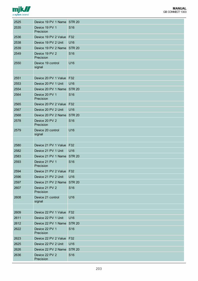
MANUALGB CONNECT 1303
203
2525 Device 19 PV 1 Name STR 20
2535 Device 19 PV 1Precision
S16
2536 Device 19 PV 2 Value F32
2538 Device 19 PV 2 Unit U16
2539 Device 19 PV 2 Name STR 20
2549 Device 19 PV 2Precision
S16
2550 Device 19 controlsignal
U16
2551 Device 20 PV 1 Value F32
2553 Device 20 PV 1 Unit U16
2554 Device 20 PV 1 Name STR 20
2564 Device 20 PV 1Precision
S16
2565 Device 20 PV 2 Value F32
2567 Device 20 PV 2 Unit U16
2568 Device 20 PV 2 Name STR 20
2578 Device 20 PV 2Precision
S16
2579 Device 20 controlsignal
U16
2580 Device 21 PV 1 Value F32
2582 Device 21 PV 1 Unit U16
2583 Device 21 PV 1 Name STR 20
2593 Device 21 PV 1Precision
S16
2594 Device 21 PV 2 Value F32
2596 Device 21 PV 2 Unit U16
2597 Device 21 PV 2 Name STR 20
2607 Device 21 PV 2Precision
S16
2608 Device 21 controlsignal
U16
2609 Device 22 PV 1 Value F32
2611 Device 22 PV 1 Unit U16
2612 Device 22 PV 1 Name STR 20
2622 Device 22 PV 1Precision
S16
2623 Device 22 PV 2 Value F32
2625 Device 22 PV 2 Unit U16
2626 Device 22 PV 2 Name STR 20
2636 Device 22 PV 2Precision
S16

MANUALGB CONNECT 1303
204
2637 Device 22 controlsignal
U16
2650 Device 1 PV 1 Min F32
2652 Device 1 PV 1 Max F32
2654 Device 1 PV 2 Min F32
2656 Device 1 PV 2 Max F32
2658 Device 2 PV 1 Min F32
2660 Device 2 PV 1 Min F32
2662 Device 2 PV 2 Max F32
2664 Device 2 PV 2 Min F32
2666 Device 3 PV 1 Max F32
2668 Device 3 PV 1 Min F32
2670 Device 3 PV 2 Min F32
2672 Device 3 PV 2 Max F32
2674 Device 4 PV 1 Min F32
2676 Device 4 PV 1 Max F32
2678 Device 4 PV 2 Min F32
2680 Device 4 PV 2 Min F32
2682 Device 5 PV 1 Max F32
2684 Device 5 PV 1 Min F32
2686 Device 5 PV 2 Max F32
2688 Device 5 PV 2 Min F32
2690 Device 6 PV 1 Min F32
2692 Device 6 PV 1 Max F32
2694 Device 6 PV 2 Min F32
2696 Device 6 PV 2 Max F32
2698 Device 7 PV 1 Min F32
2700 Device 7 PV 1 Min F32
2702 Device 7 PV 2 Max F32
2704 Device 7 PV 2 Min F32
2706 Device 8 PV 1 Max F32
2708 Device 8 PV 1 Min F32
2710 Device 8 PV 2 Min F32
2712 Device 8 PV 2 Max F32
2714 Device 9 PV 1 Min F32
2716 Device 9 PV 1 Max F32
2718 Device 9 PV 2 Min F32
2720 Device 9 PV 2 Min F32
2722 Device 10 PV 1 Max F32
2724 Device 10 PV 1 Min F32

MANUALGB CONNECT 1303
205
2726 Device 10 PV 2 Max F32
2728 Device 10 PV 2 Min F32
2730 Device 11 PV 1 Min F32
2732 Device 11 PV 1 Max F32
2734 Device 11 PV 2 Min F32
2736 Device 11 PV 2 Max F32
2738 Device 12 PV 1 Min F32
2740 Device 12 PV 1 Min F32
2742 Device 12 PV 2 Max F32
2744 Device 12 PV 2 Min F32
2746 Device 13 PV 1 Max F32
2748 Device 13 PV 1 Min F32
2750 Device 13 PV 2 Min F32
2752 Device 13 PV 2 Max F32
2754 Device 14 PV 1 Min F32
2756 Device 14 PV 1 Max F32
2758 Device 14 PV 2 Min F32
2760 Device 14 PV 2 Min F32
2762 Device 15 PV 1 Max F32
2764 Device 15 PV 1 Min F32
2766 Device 15 PV 2 Max F32
2768 Device 15 PV 2 Min F32
2770 Device 16 PV 1 Min F32
2772 Device 16 PV 1 Max F32
2774 Device 16 PV 2 Min F32
2776 Device 16 PV 2 Max F32

MANUALGB CONNECT 1303
206
Customized RegisterModbusaddress
Description Data type Command
57000 customized register list start U16 R/W
57255 customized register list stop U16 R/W

MANUALGB CONNECT 1303
207
State MachineModbusaddress
Description Data type Commands
40000 State Machine 1 U32 R/W
40400 State Machine 2 U32 R/W
40800 State Machine 3 U32 R/W
41200 State Machine 4 U32 R/W
41600 State Machine 5 U32 R/W
42000 State Machine 6 U32 R/W
42400 State Machine 7 U32 R/W
42800 State Machine 8 U32 R/W
43200 State Machine 9 U32 R/W
43600 State Machine 10 U32 R/W
44010 State Machine 1pointer
U16 Read Only
44011 State Machine 2pointer
U16 Read Only
44012 State Machine 3pointer
U16 Read Only
44013 State Machine 4pointer
U16 Read Only
44014 State Machine 5pointer
U16 Read Only
44015 State Machine 6pointer
U16 Read Only
44016 State Machine 7pointer
U16 Read Only
44017 State Machine 8pointer
U16 Read Only
44018 State Machine 9pointer
U16 Read Only
44019 State Machine 10pointer
U16 Read Only
44020 State Machine Write protection
U32{Low} R/W protection code is "45560656", it resets all state machines andenables WRITE to commends
U32{High} The protection code resets at "No Carrier" or at power-up

MANUALGB CONNECT 1303
208
Display menus, Flowcharts

MANUALGB CONNECT 1303
209
Functions menu - units generalUnits in the DisplayMeasuring units is configured several places in the navigations menu, the selectable units are the same in all levels ofthe menu, and shown here.

MANUALGB CONNECT 1303
210
Pump Control 1
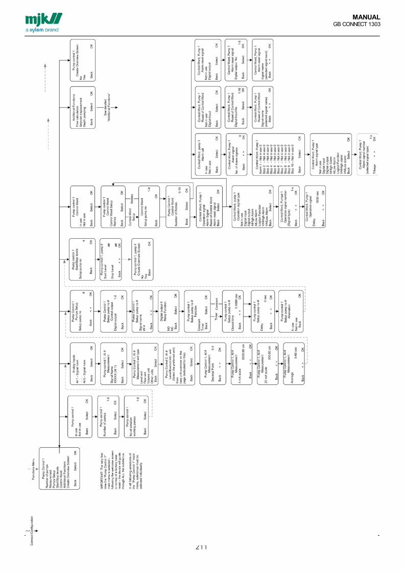
MANUALGB CONNECT 1303
211

MANUALGB CONNECT 1303
212
Pumpestyring 1 Tillægsfunktioner - Display flowchart

MANUALGB CONNECT 1303
213
Pump Control 2

MANUALGB CONNECT 1303
214
Energy optimized Pumpcontrol

MANUALGB CONNECT 1303
215
Energi optimeret pumpestyring, fortsat
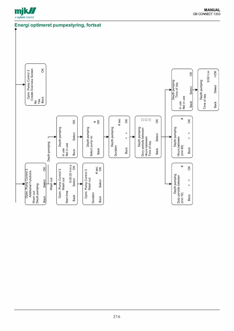
MANUALGB CONNECT 1303
216
Energi optimeret pumpestyring, fortsat
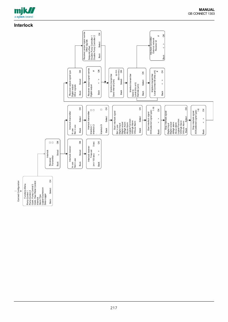
MANUALGB CONNECT 1303
217
Interlock
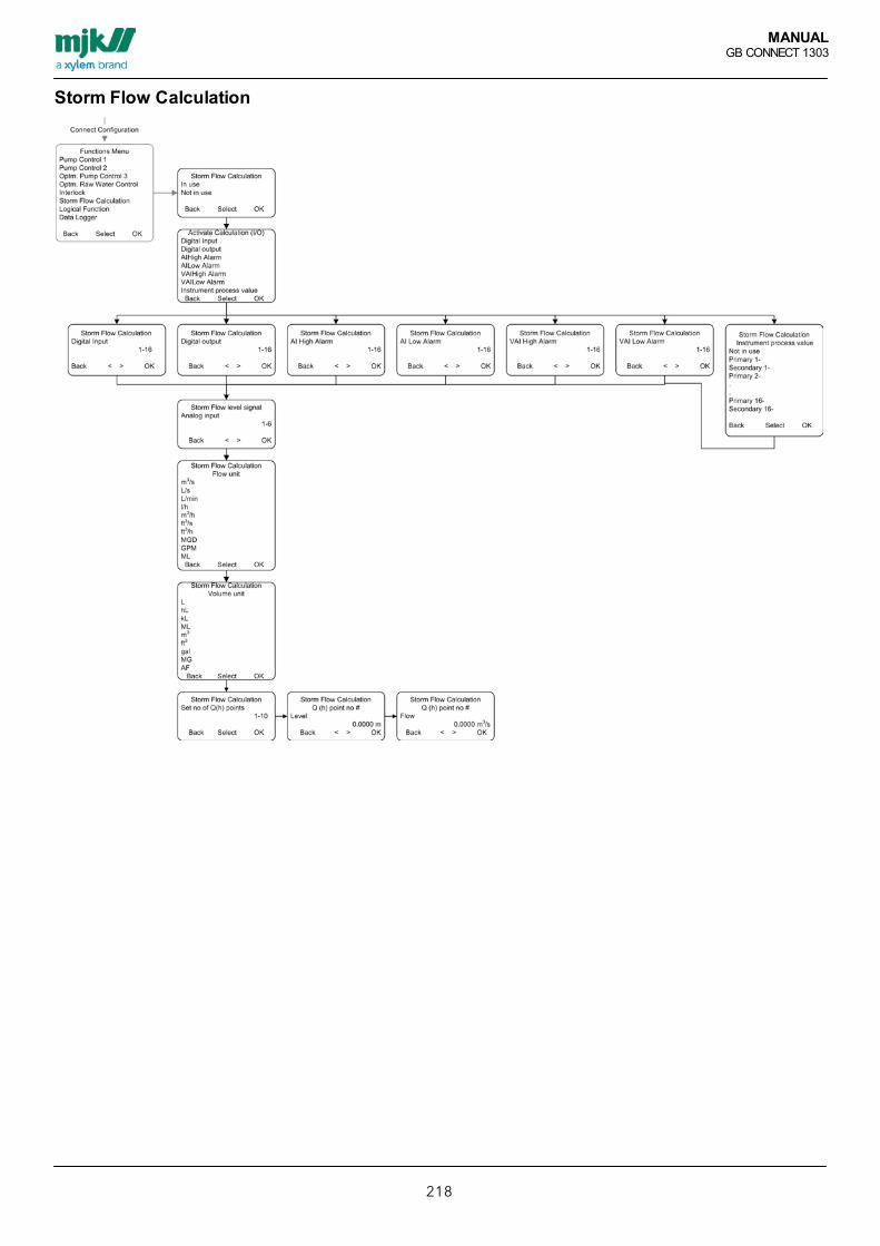
MANUALGB CONNECT 1303
218
Storm Flow Calculation
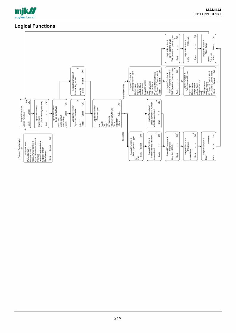
MANUALGB CONNECT 1303
219
Logical Functions
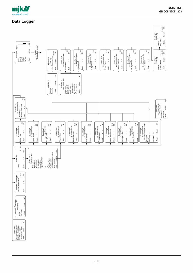
MANUALGB CONNECT 1303
220
Data Logger

MANUALGB CONNECT 1303
221
Display Data Logger

MANUALGB CONNECT 1303
222
I/O Signals

MANUALGB CONNECT 1303
223
Digital Input & Output

MANUALGB CONNECT 1303
224
Analog input

MANUALGB CONNECT 1303
225
Analog Output

MANUALGB CONNECT 1303
226
Virtual Analog Input

MANUALGB CONNECT 1303
227
Alarm SetupAlarm Setup
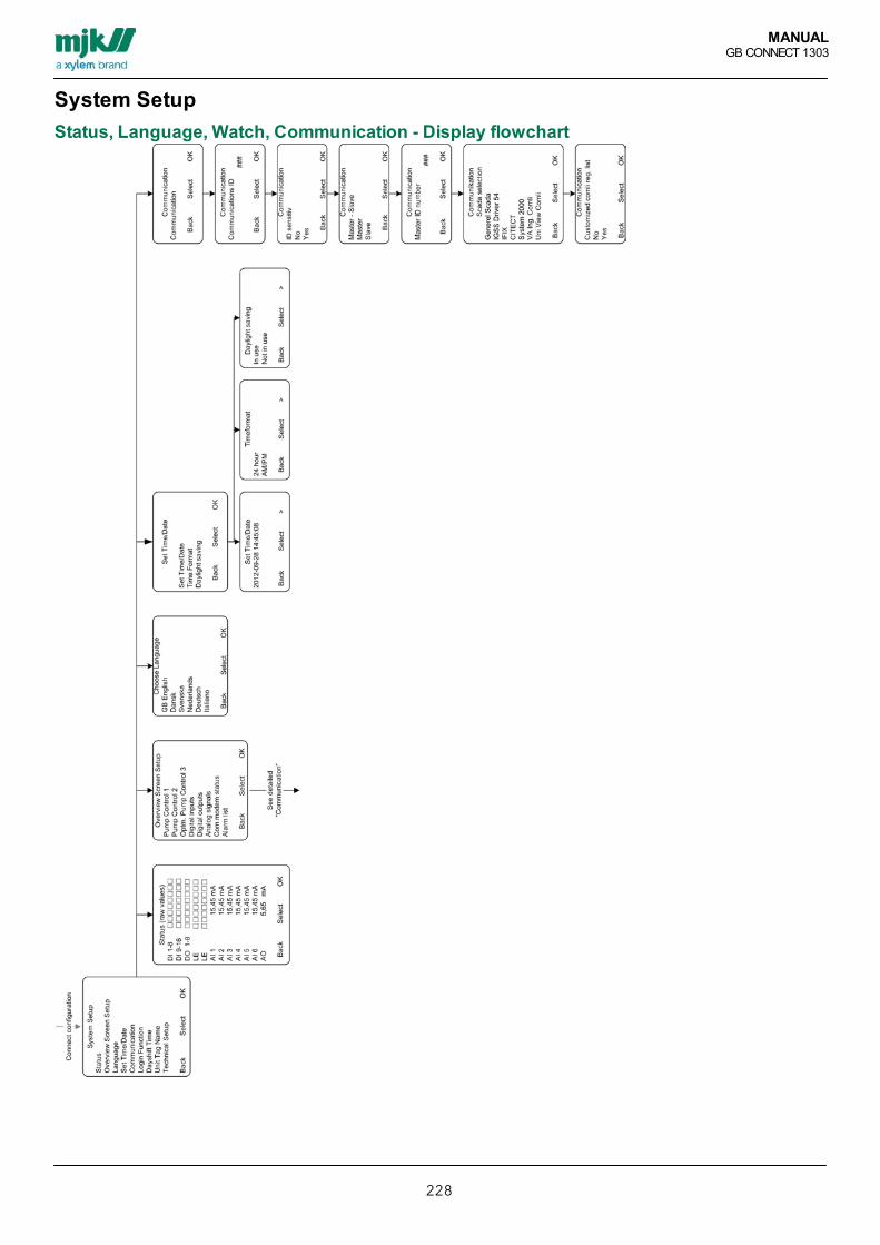
MANUALGB CONNECT 1303
228
System SetupStatus, Language, Watch, Communication - Display flowchart

MANUALGB CONNECT 1303
229
Overview Screen

MANUALGB CONNECT 1303
230
Access code, Day Shift, Unit Tag Name
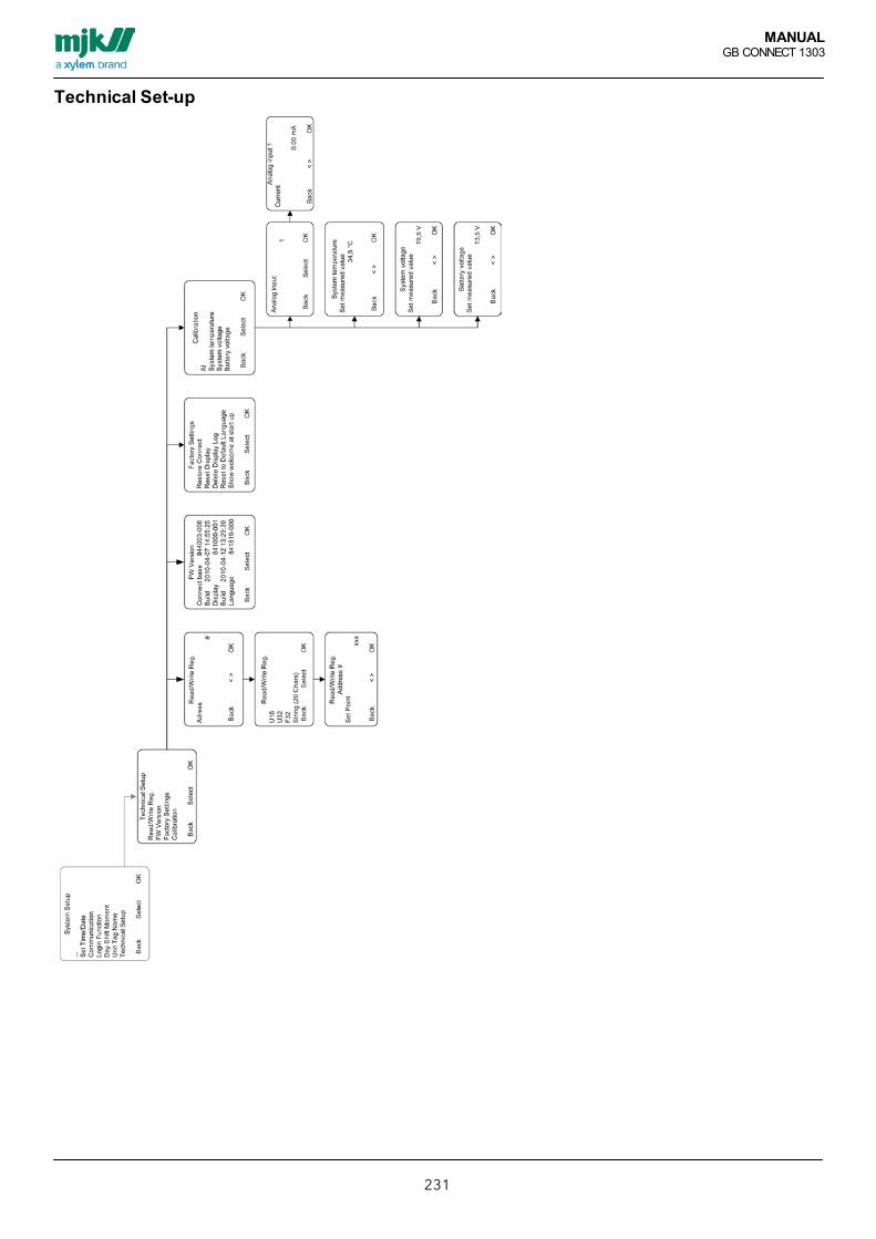
MANUALGB CONNECT 1303
231
Technical Set-up

MANUALGB CONNECT 1303
232
Network Setup

MANUALGB CONNECT 1303
233
Display pop-up alarms and notificationsAlarm
Name Description
Current overrange mA does not match 4 - 20 mA. e.g. 3,5 or 20,5 mA.
Factory resetoccurred
reset to factory settings is performed. certain settings are changed. check all settings.
High alarm High set point has been detected.
Low alarm Low set point has been detected.
mA connection The mA connection is not connected. If the current-out is used, deactivate mA Current out to stop thisalarm.
NotificationsName Description
Eeprom write error Error - Eeprom writing failure. In case of repeated notifications call an MJK technician.
System Error - Internal VCC error. see event log for details
System error Error - System software not working inclusive failure alarm and/or sensor parts. Contact MJK.
WarningsName Description
InfoName Description
System resetoccurred
Info - Converter have performed a software update and/or hardware reset.

MANUALGB CONNECT 1303
234
USBName Description
Flash programmingplease wait
Programming in progress but not finished.
Flash programmingdone
Programming finished.
Flash crc error Cyclic redundancy check error.
Unknown commandflash user text
Invalid command issued.
Flash addressoverrun
writing failure occurred
File phase error Internal USB failure.
File write failure writing failure occurred
USB protocoloverrun
Communications error occurred.

1) The tissue in plants that brings water upward from the roots;2) A leading global water technology company.
We’re 12,700 people unified in a common purpose: creating innovative solutionsto meet our world’s water needs. Developing new technologies that will improvethe way water is used, conserved, and re-used in the future is central to our work.We move, treat, analyze, and return water to the environment, and we help peopleuse water efficiently, in their homes, buildings, factories and farms. In more than150 countries, we have strong, long-standing relationships with customers whoknow us for our powerful combination of leading product brands and applicationsexpertise, backed by a legacy of innovation.
For more information on how Xylem can help you, go to www.xyleminc.com
Xylem
MJK Automation A/SByageren 7DK-2850 NærumDenmarkTel +45 45 56 06 56Fax +45 45 56 06 46www.mjk.com
Connect, MµConnect, Chatter, MagFlux, Oxix, pHix compact, Shuttle and SuSix are registrered trademarks of MJK Automation A/S. © 2013 Xylem, Inc. BROCHUR PROFIL 01 2013
C
E RT I F I E D
IS
O 9001-2008