Embed Size (px)
Citation preview
CONTROL STRATEGIES FOR IMPROVING SYSTEM OPERATION
NPSC 2008 IIT BOMBAYBOMBAYK.R.PADIYAR
K.R.Padiyar I.I.Sc.
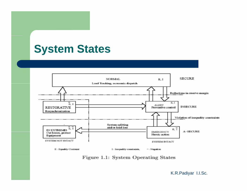
System States
K.R.Padiyar I.I.Sc.
Control Objectives
In Normal Secure State: Power/Frequency (P/F) d R ti P /V lt (Q/V)(P/F) and Reactive Power/Voltage (Q/V) controlI St t P ti t l (I f iblInsecure State: Preventive control (Infeasible in systems with power shortages)Emergency State: Emergency control toEmergency State: Emergency control to remove limit violations and stabilize the system
K.R.Padiyar I.I.Sc.
system
Control Objectives
In Extremis State: Control to cut losses and t t th t (N t th t hprotect the system (Note: the system has
already separated into islands that have to be protected to prevent further collapse)be protected to prevent further collapse)In Restorative State: Resynchronization to restore loads and system integrityrestore loads and system integrity
K.R.Padiyar I.I.Sc.
Complexities in System Operation
1. In steady state, all generators have to operate synchronouslyoperate synchronously.
2. Fast and efficient energy storage devices are not yet available for practical use.are not yet available for practical use.
3. The electrical power flows at speeds approaching that of light.
NOTE: 2 and 3 imply that at any time the generated power equals load plus losses
K.R.Padiyar I.I.Sc.
Complexities
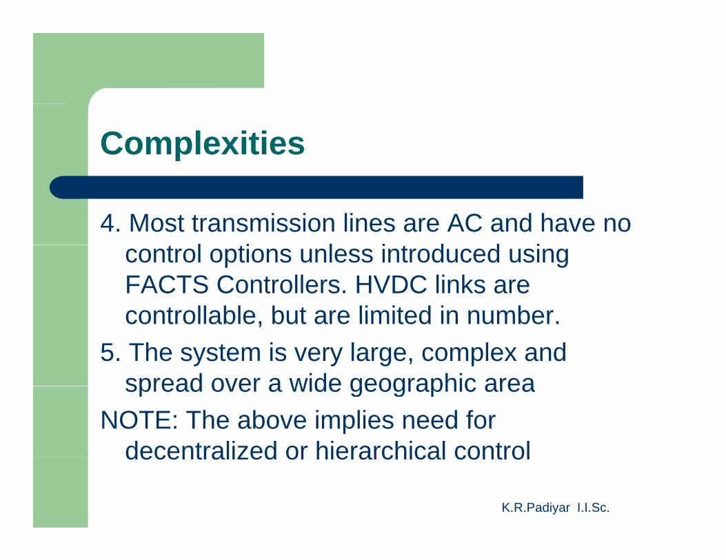
4. Most transmission lines are AC and have no t l ti l i t d d icontrol options unless introduced using
FACTS Controllers. HVDC links are controllable but are limited in numbercontrollable, but are limited in number.
5. The system is very large, complex and spread over a wide geographic areaspread over a wide geographic area
NOTE: The above implies need for decentralized or hierarchical control
K.R.Padiyar I.I.Sc.
decentralized or hierarchical control
Complexities
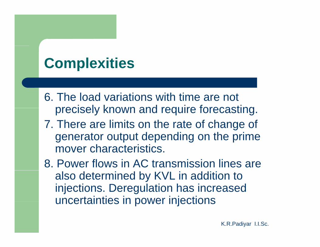
6. The load variations with time are not precisely known and require forecastingprecisely known and require forecasting.
7. There are limits on the rate of change of generator output depending on the primegenerator output depending on the prime mover characteristics.
8. Power flows in AC transmission lines are also determined by KVL in addition to injections. Deregulation has increased uncertainties in power injections
K.R.Padiyar I.I.Sc.
uncertainties in power injections
Complexities
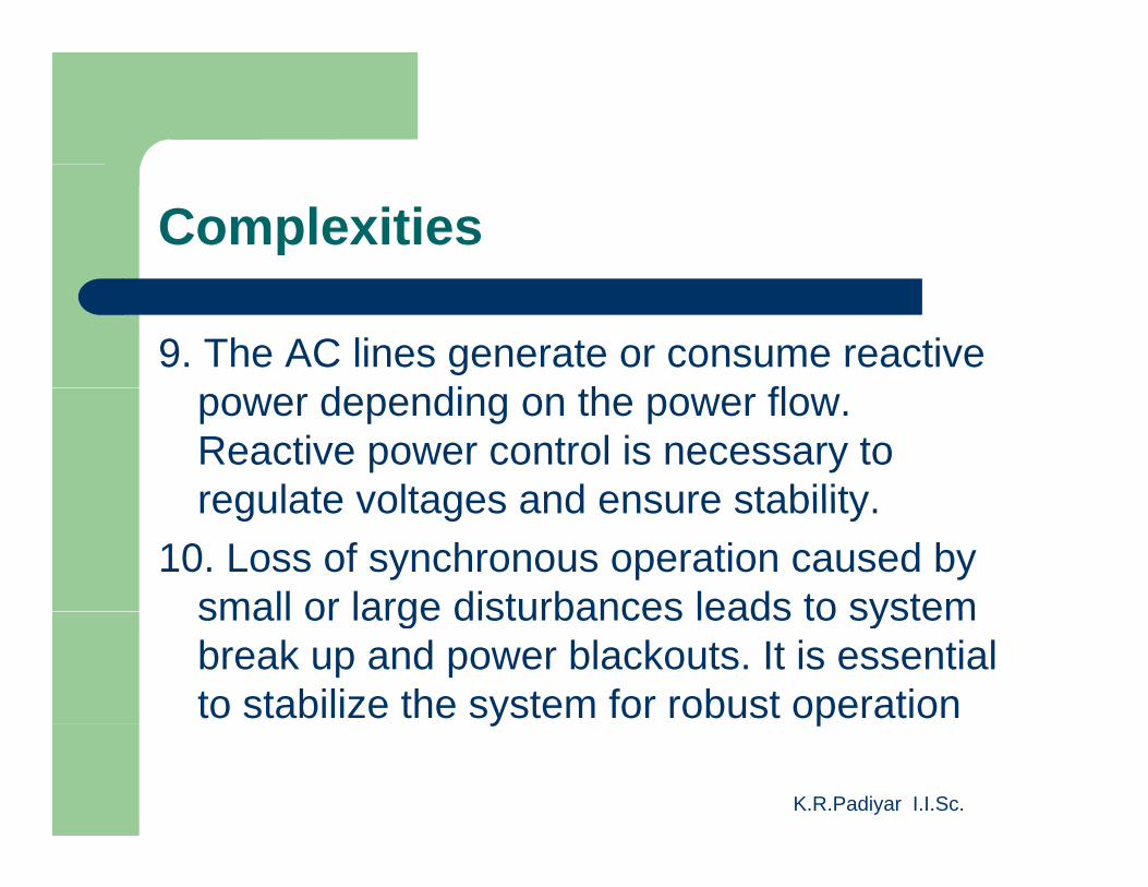
9. The AC lines generate or consume reactive d di th flpower depending on the power flow.
Reactive power control is necessary to regulate voltages and ensure stabilityregulate voltages and ensure stability.
10. Loss of synchronous operation caused by small or large disturbances leads to systemsmall or large disturbances leads to system break up and power blackouts. It is essential to stabilize the system for robust operation
K.R.Padiyar I.I.Sc.
y p
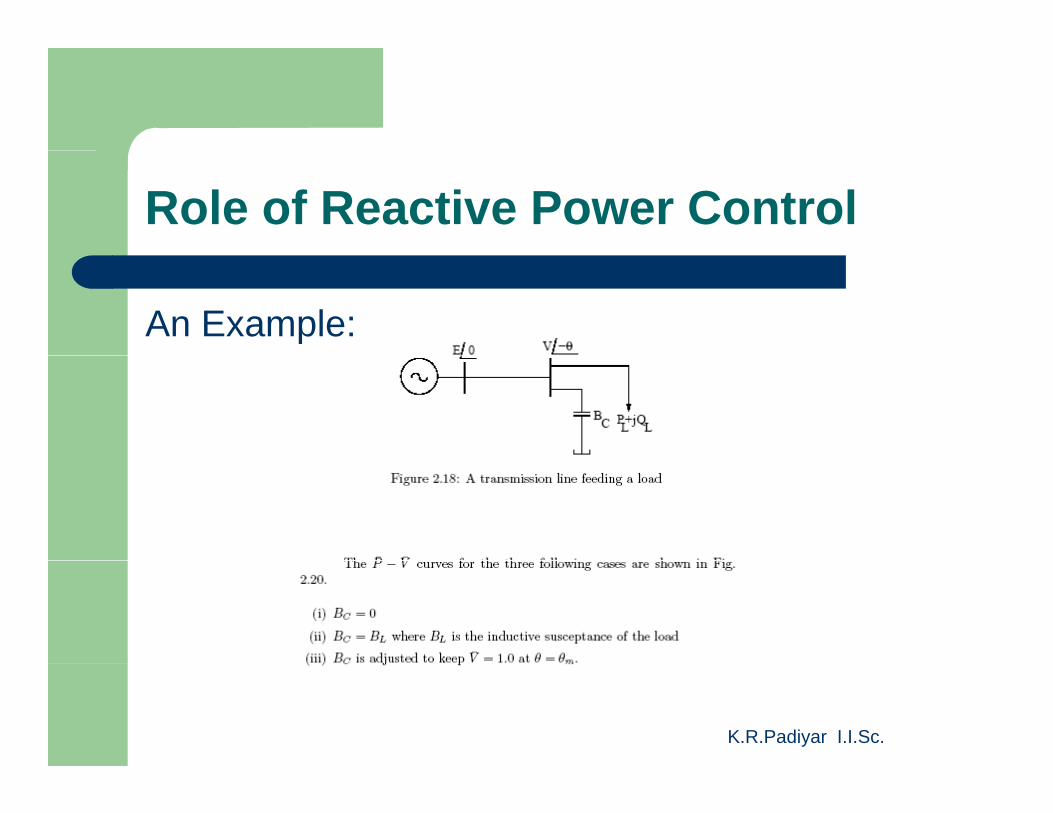
Role of Reactive Power Control
An Example:
K.R.Padiyar I.I.Sc.
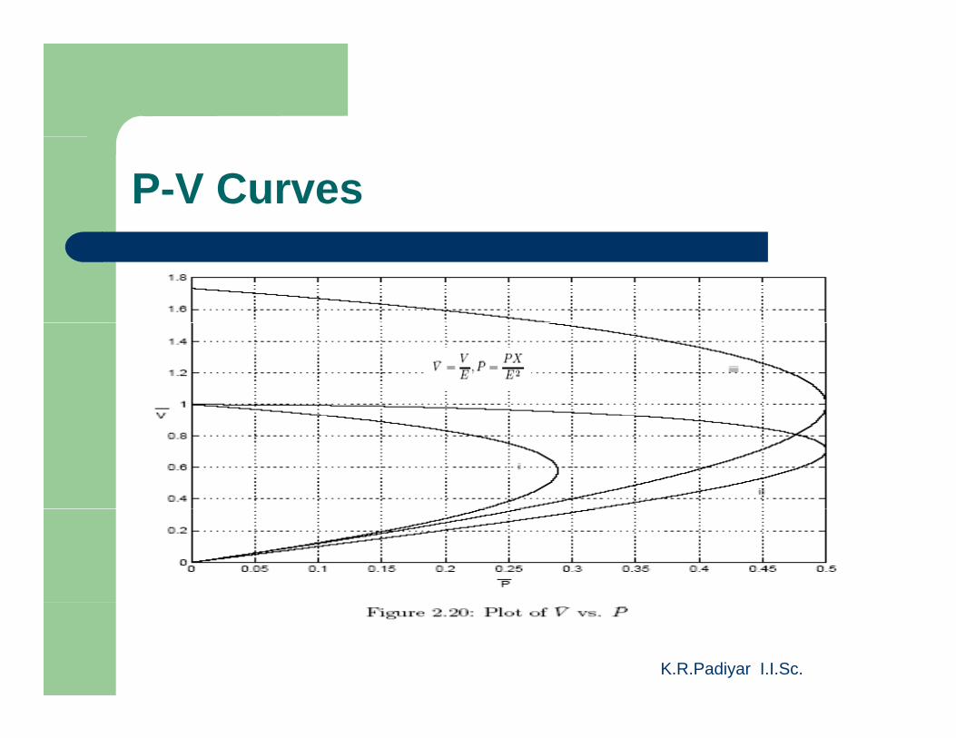
P-V Curves
K.R.Padiyar I.I.Sc.
Role of Reactive Power Control
K.R.Padiyar I.I.Sc.
A Suggestion
It is desirable to supply controllable reactive f i d d t thpower from an independent source rather
than a generator as the cost of generation can be 20 25 times the cost of reactivecan be 20-25 times the cost of reactive power source. The generator should typically operate at rated power factor (particularly p p (p yunder power shortage situations)
K.R.Padiyar I.I.Sc.
Design of Damping Controllers
K.R.Padiyar I.I.Sc.
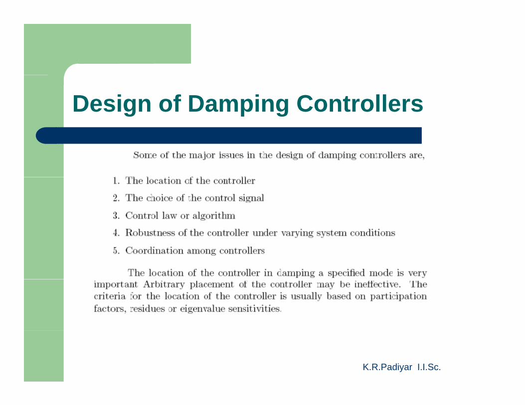
Design of Damping Controllers
K.R.Padiyar I.I.Sc.
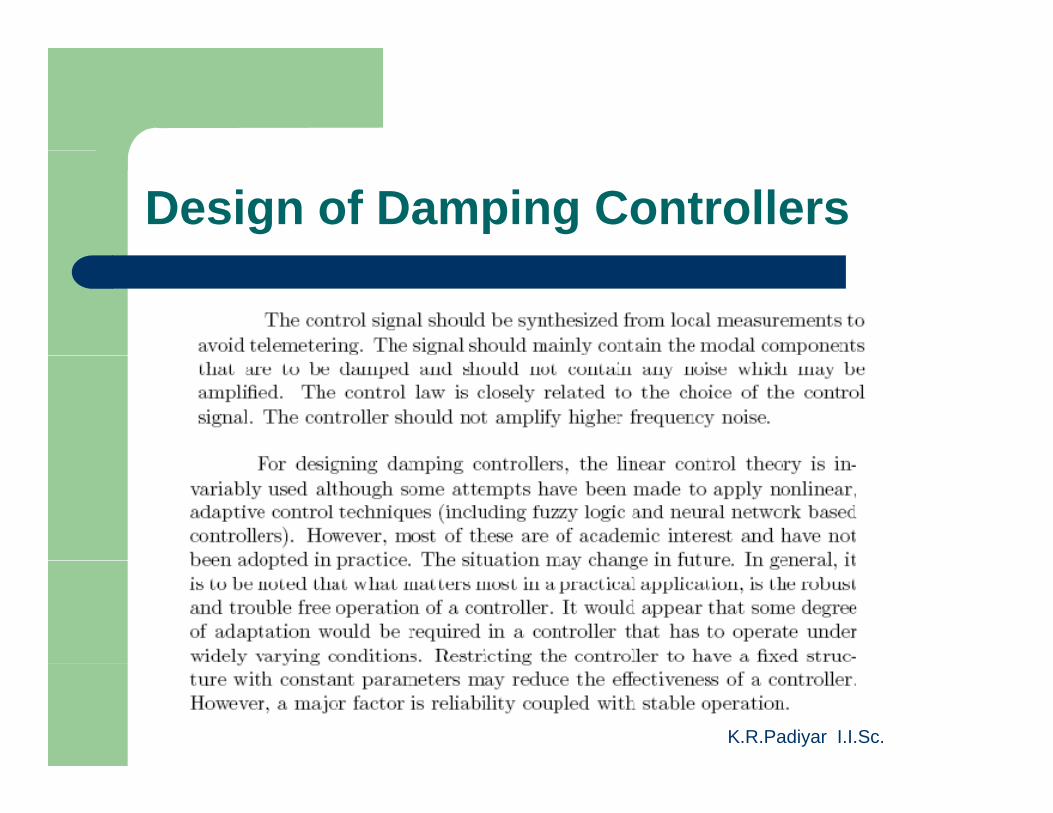
Design of Damping Controllers
K.R.Padiyar I.I.Sc.
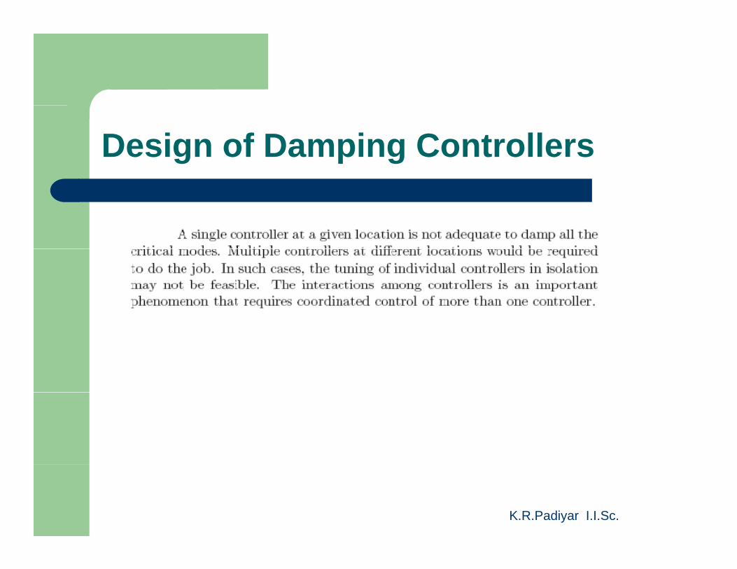
Design of Damping Controllers
K.R.Padiyar I.I.Sc.
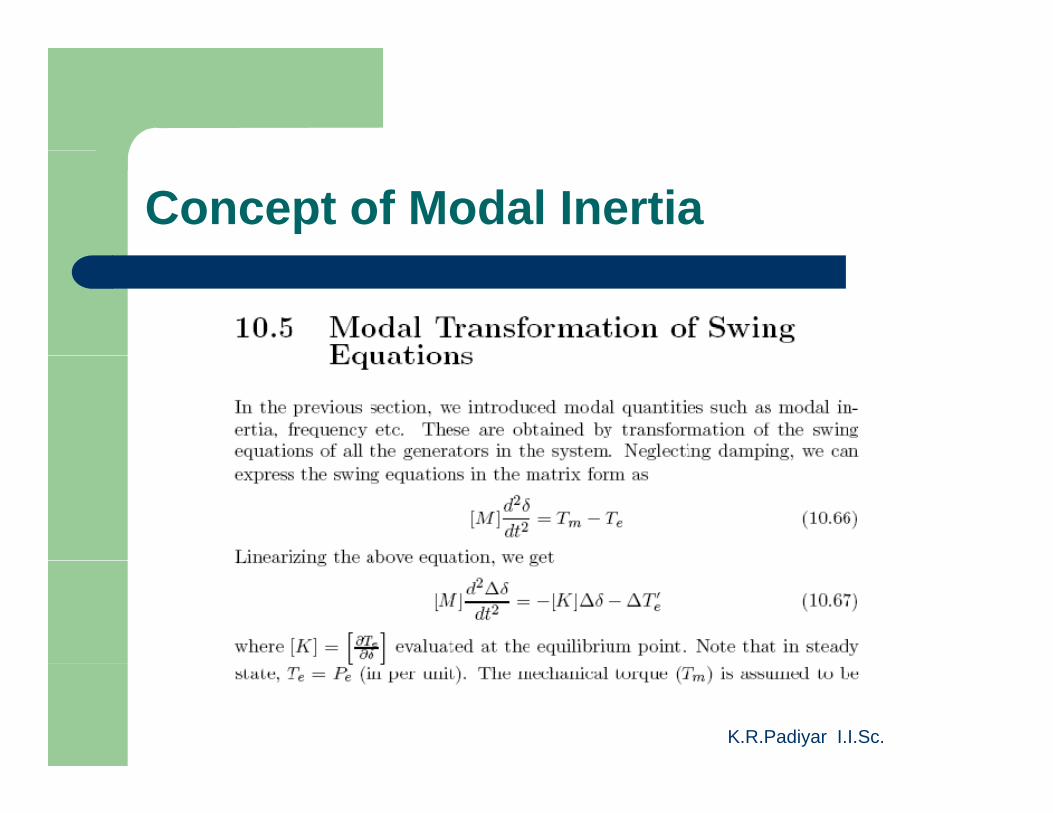
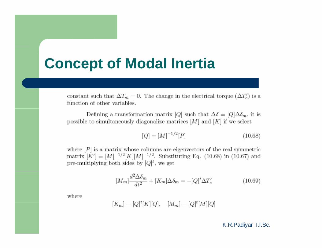
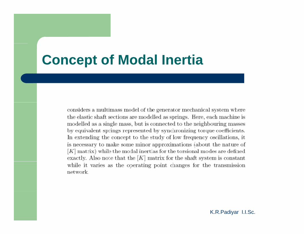
Concept of Modal Inertia
K.R.Padiyar I.I.Sc.
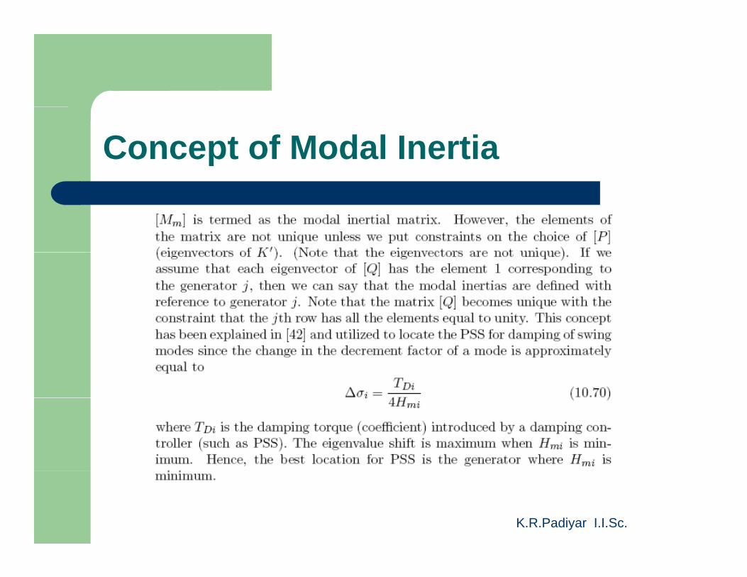
Concept of Modal Inertia
K.R.Padiyar I.I.Sc.
Concept of Modal Inertia
K.R.Padiyar I.I.Sc.
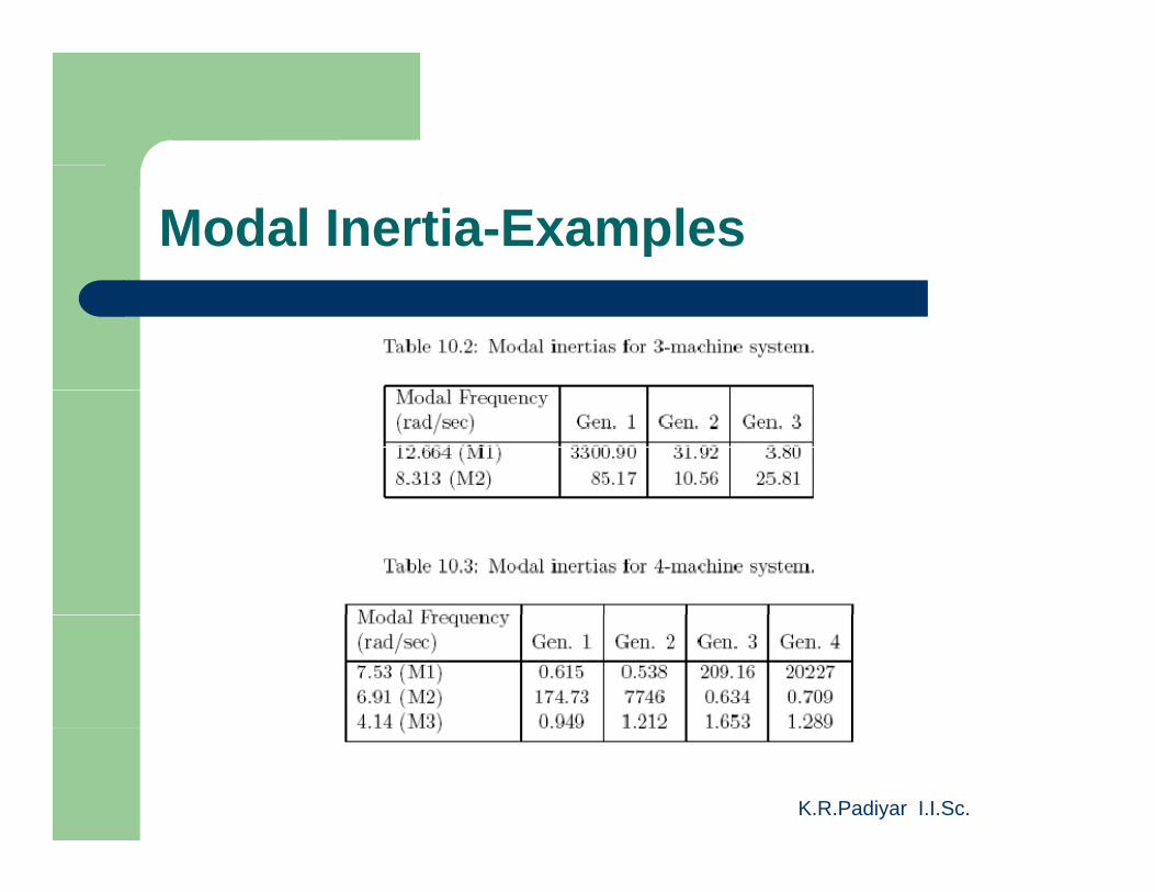
Modal Inertia-Examples
K.R.Padiyar I.I.Sc.
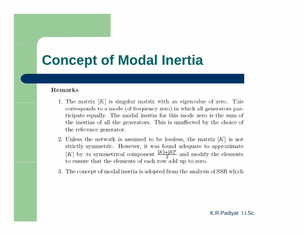
Concept of Modal Inertia
K.R.Padiyar I.I.Sc.
Concept of Modal Inertia
K.R.Padiyar I.I.Sc.

Application of MI for POD Design
K.R.Padiyar I.I.Sc.

Damping of Power Oscillations
K.R.Padiyar I.I.Sc.
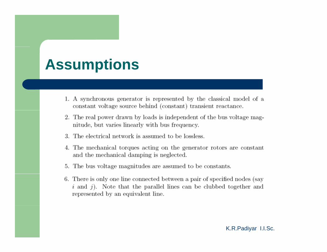
Assumptions
K.R.Padiyar I.I.Sc.
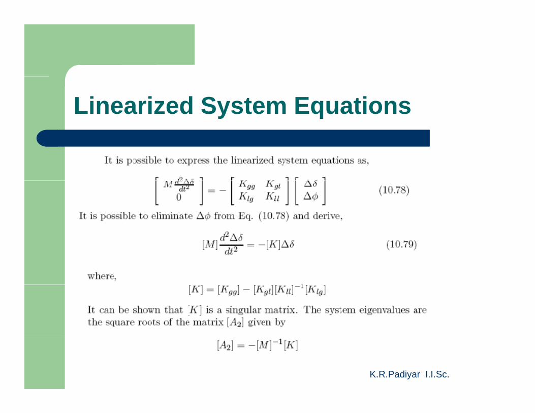
Linearized System Equations
K.R.Padiyar I.I.Sc.
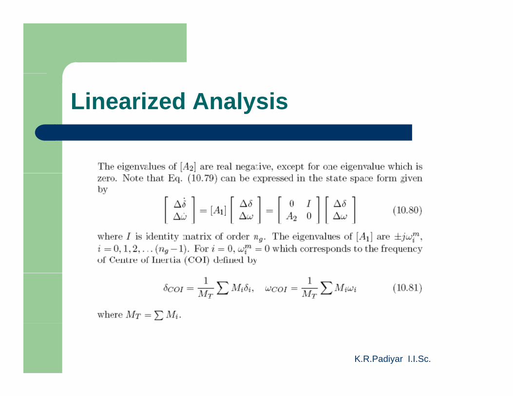
Linearized Analysis
K.R.Padiyar I.I.Sc.
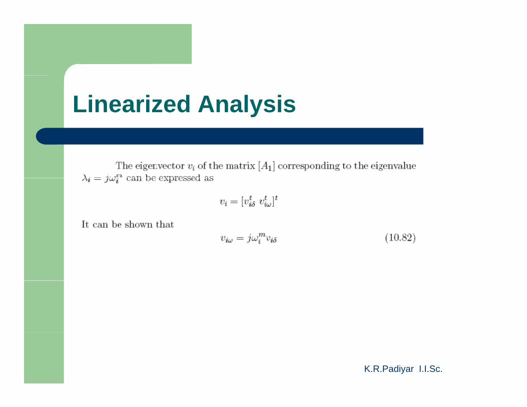
Linearized Analysis
K.R.Padiyar I.I.Sc.
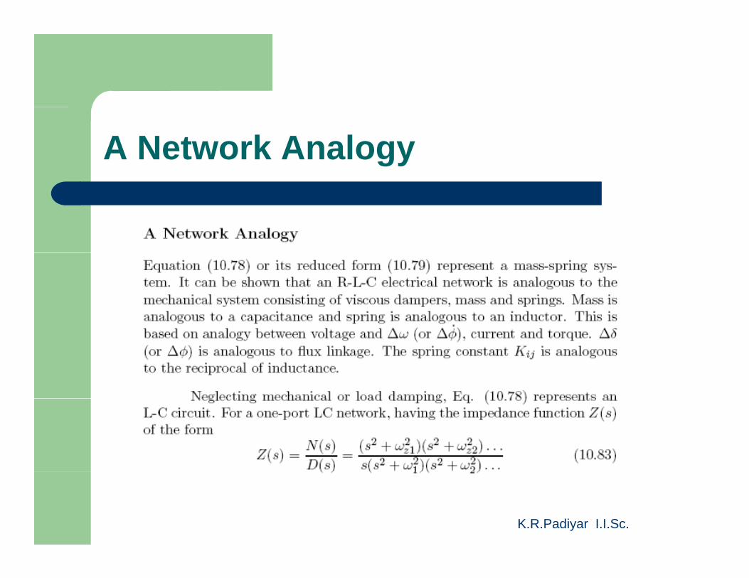
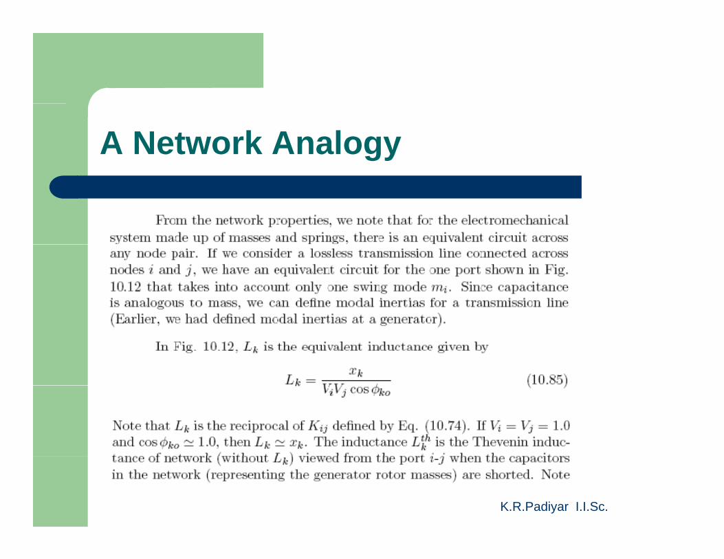
A Network Analogy
K.R.Padiyar I.I.Sc.
A Network Analogy
K.R.Padiyar I.I.Sc.
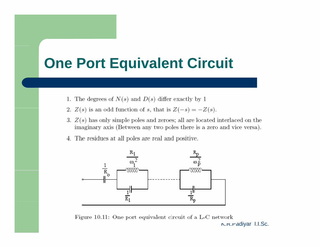
One Port Equivalent Circuit
K.R.Padiyar I.I.Sc.
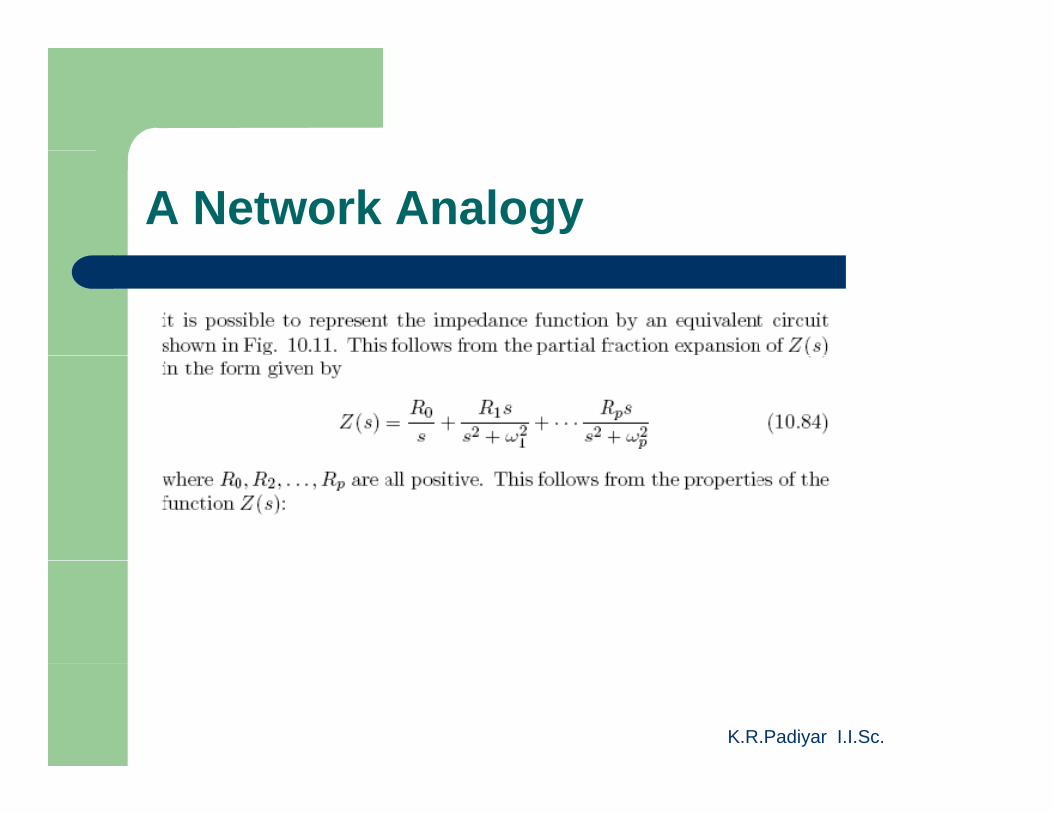
A Network Analogy
K.R.Padiyar I.I.Sc.
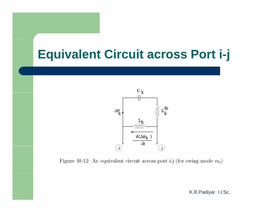
Equivalent Circuit across Port i-j
K.R.Padiyar I.I.Sc.
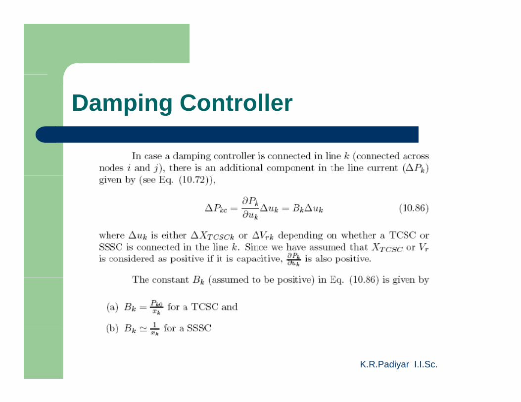
Damping Controller
K.R.Padiyar I.I.Sc.
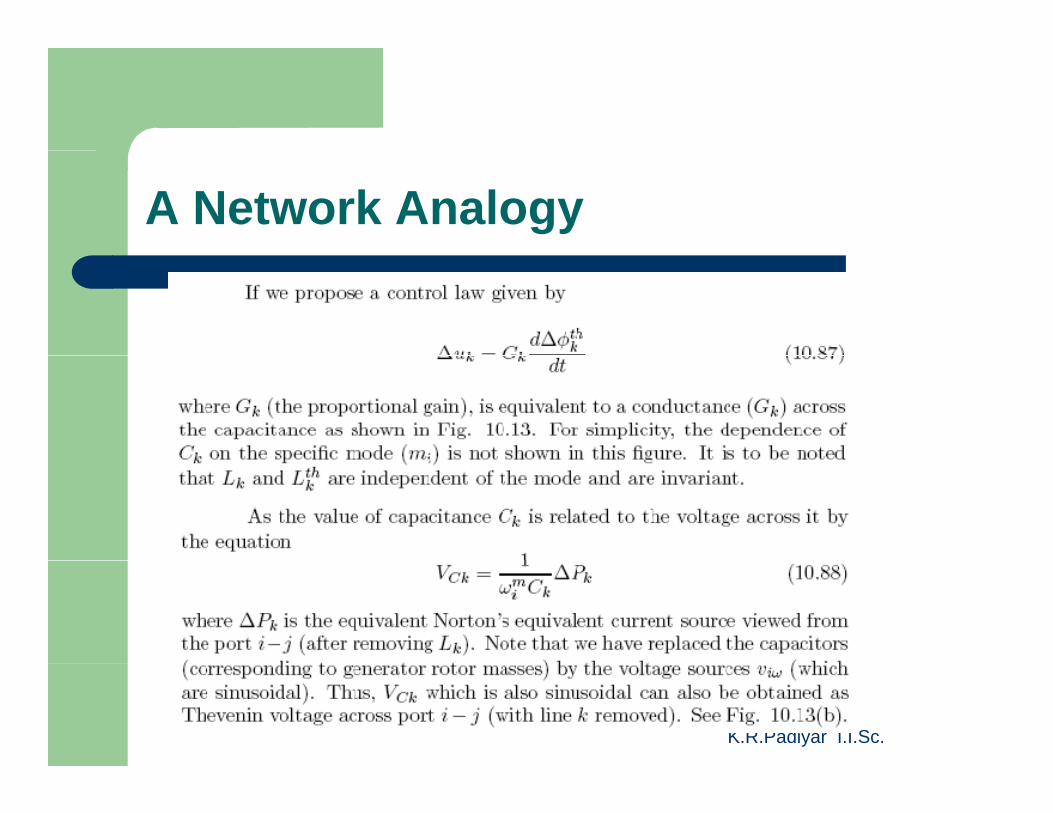
A Network Analogy
K.R.Padiyar I.I.Sc.
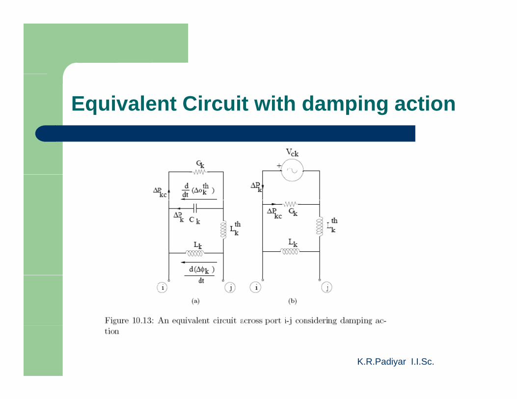
Equivalent Circuit with damping action
K.R.Padiyar I.I.Sc.
Damping Control Law
K.R.Padiyar I.I.Sc.
Location of damping Controller
K.R.Padiyar I.I.Sc.
Location of Damping Controller
K.R.Padiyar I.I.Sc.
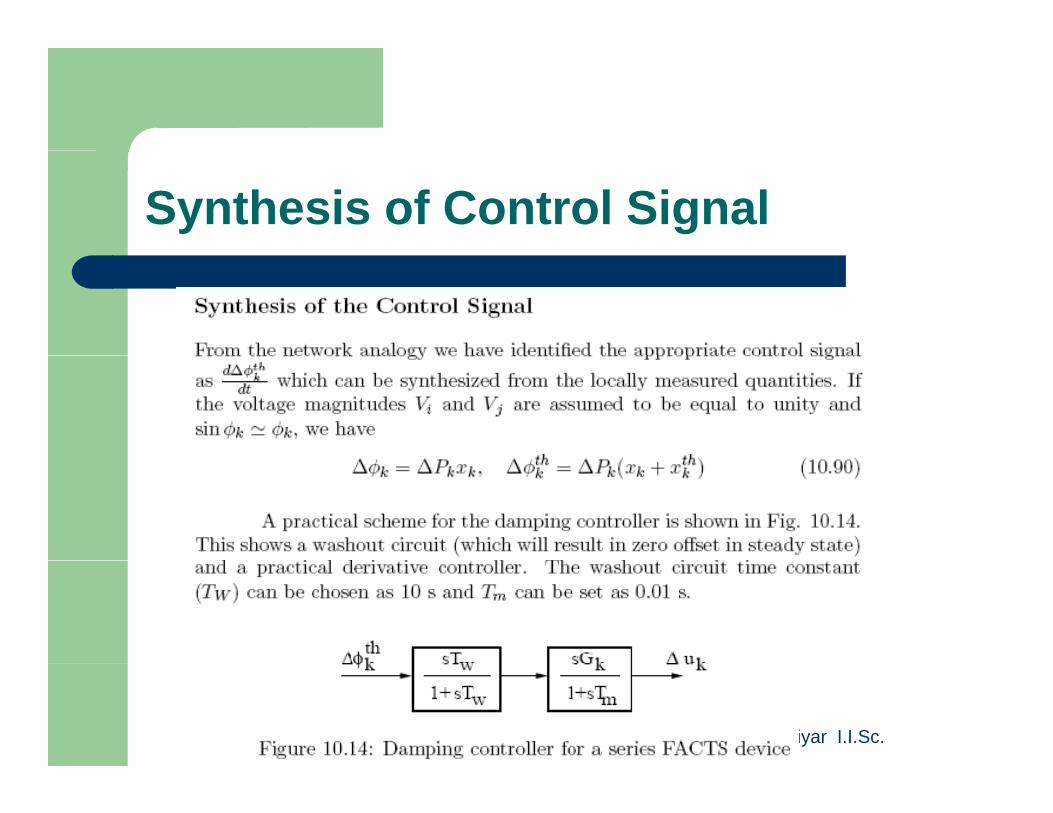
Synthesis of Control Signal
K.R.Padiyar I.I.Sc.
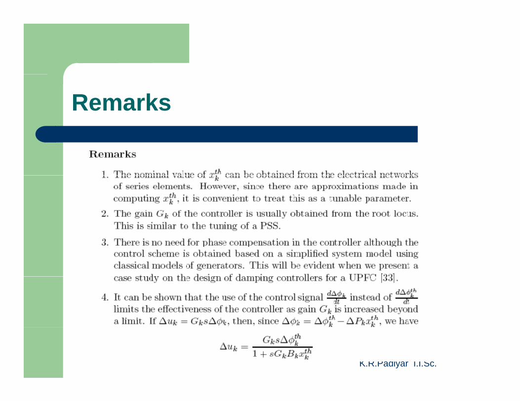
Remarks
K.R.Padiyar I.I.Sc.
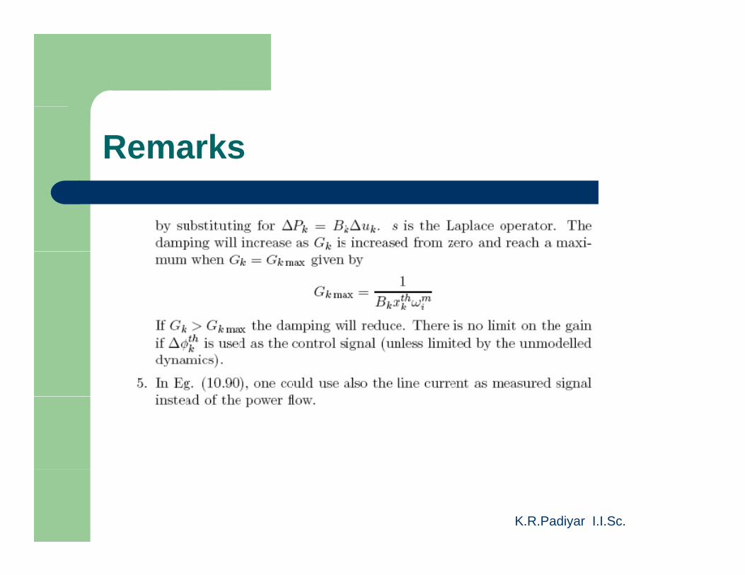
Remarks
K.R.Padiyar I.I.Sc.
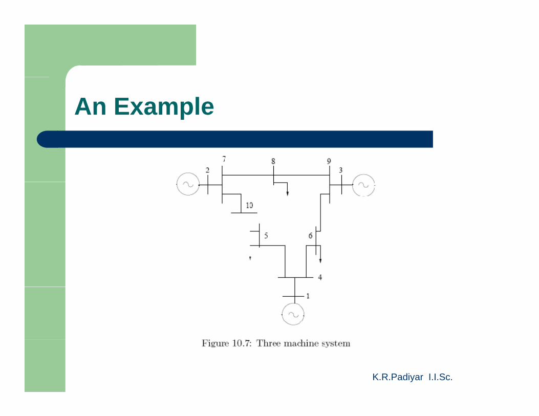
An Example
K.R.Padiyar I.I.Sc.
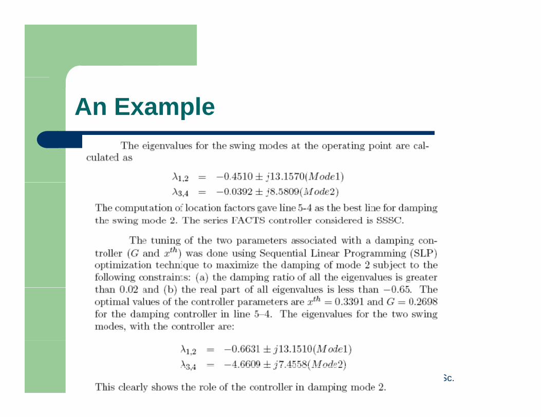
An Example
K.R.Padiyar I.I.Sc.

D i f P O ill ti U iDamping of Power Oscillations Using Shunt FACTS Controllers
K.R.Padiyar I.I.Sc.
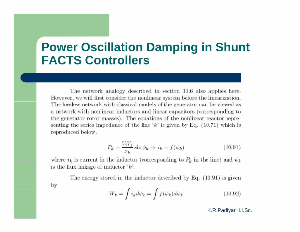
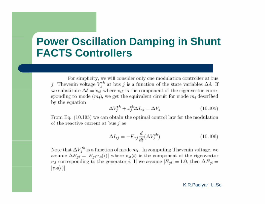
P O ill ti D i i Sh tPower Oscillation Damping in Shunt FACTS Controllers
K.R.Padiyar I.I.Sc.
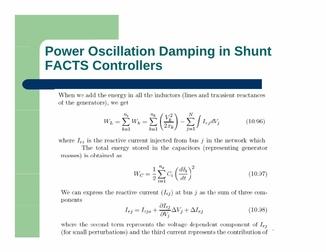
P O ill ti D i i Sh tPower Oscillation Damping in Shunt FACTS Controllers
K.R.Padiyar I.I.Sc.
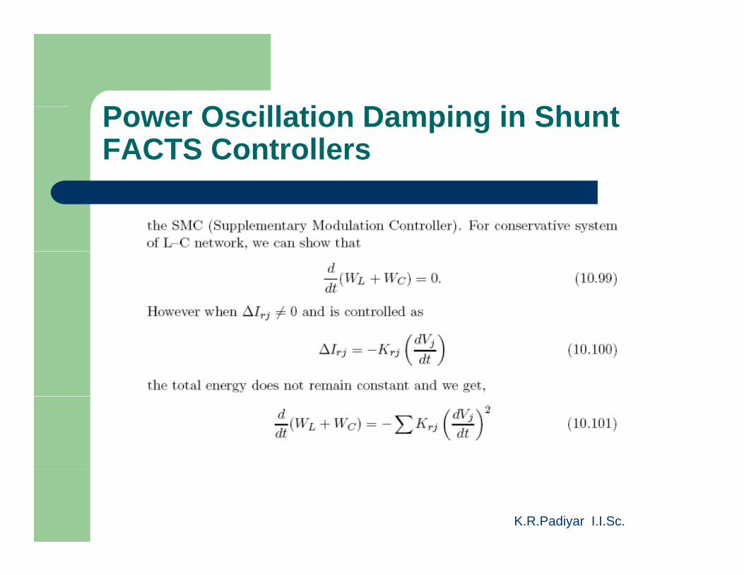
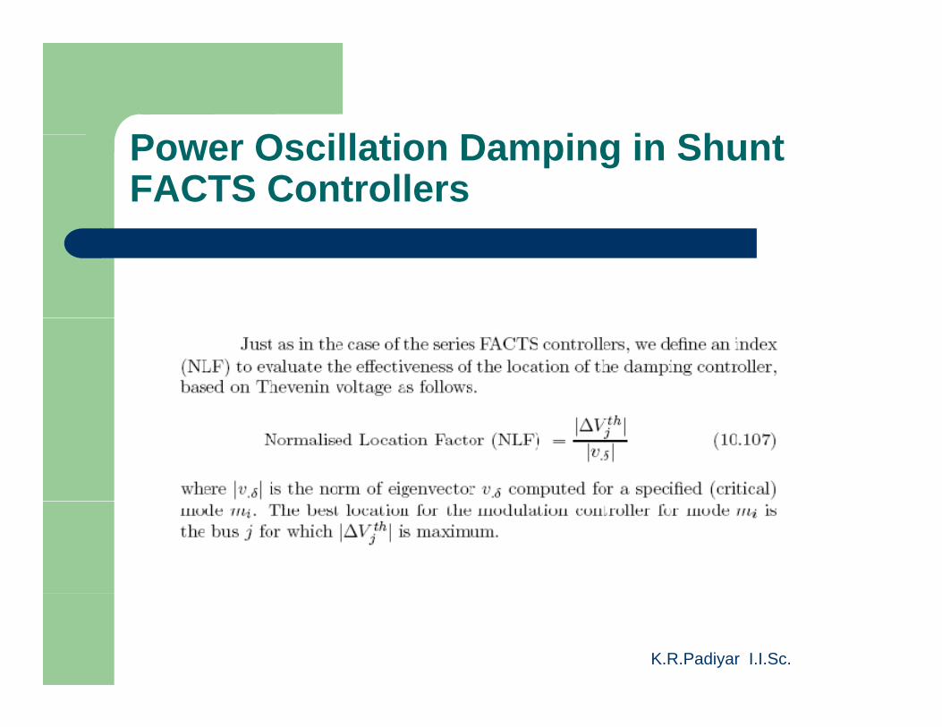
P O ill ti D i i Sh tPower Oscillation Damping in Shunt FACTS Controllers
K.R.Padiyar I.I.Sc.
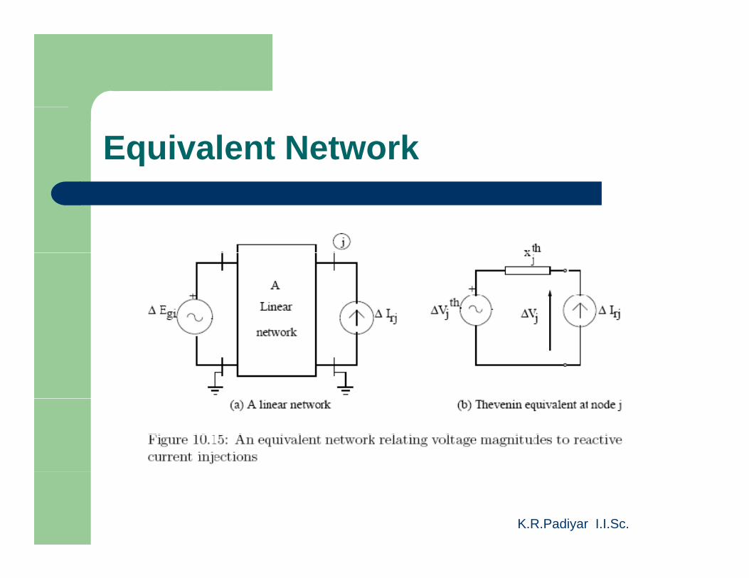
Equivalent Network
K.R.Padiyar I.I.Sc.
P O ill ti D i i Sh tPower Oscillation Damping in Shunt FACTS Controllers
K.R.Padiyar I.I.Sc.
P O ill ti D i i Sh tPower Oscillation Damping in Shunt FACTS Controllers
K.R.Padiyar I.I.Sc.
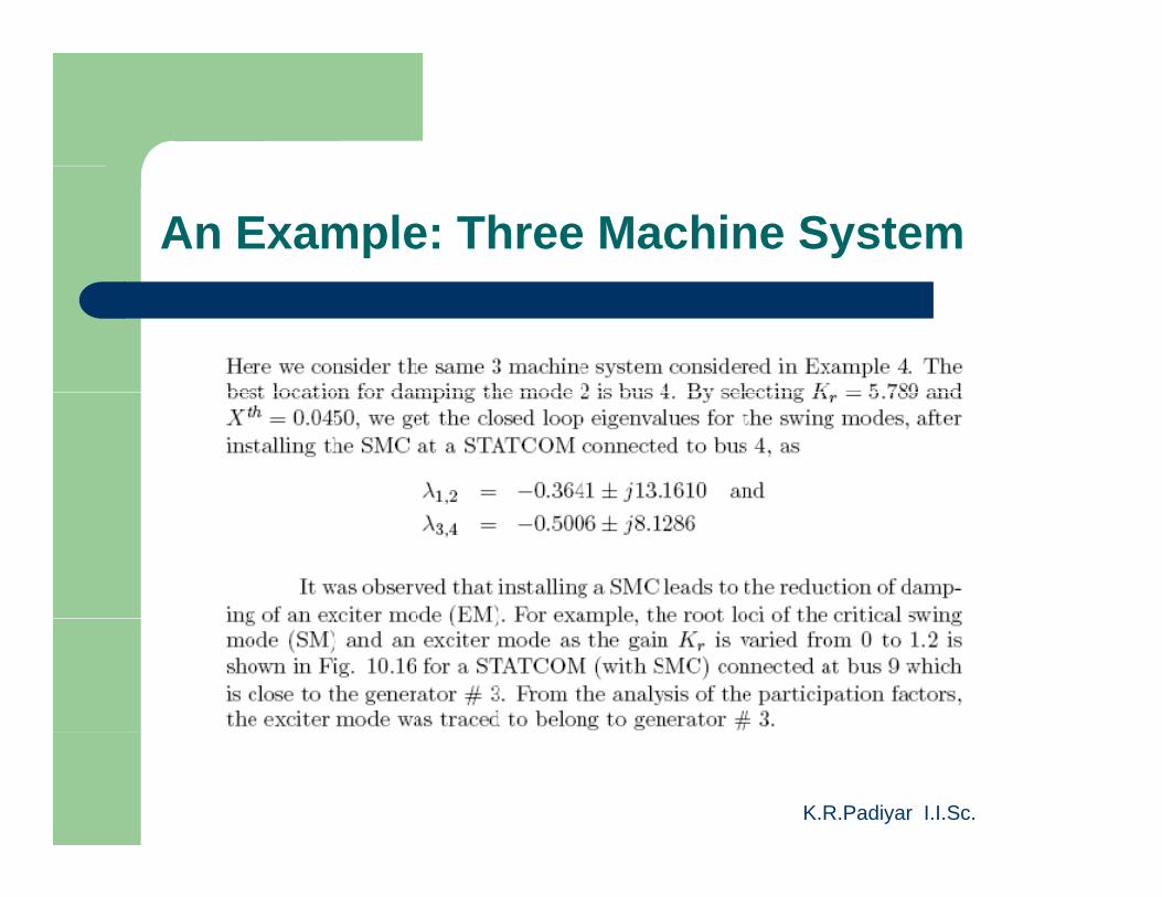
An Example: Three Machine System
K.R.Padiyar I.I.Sc.
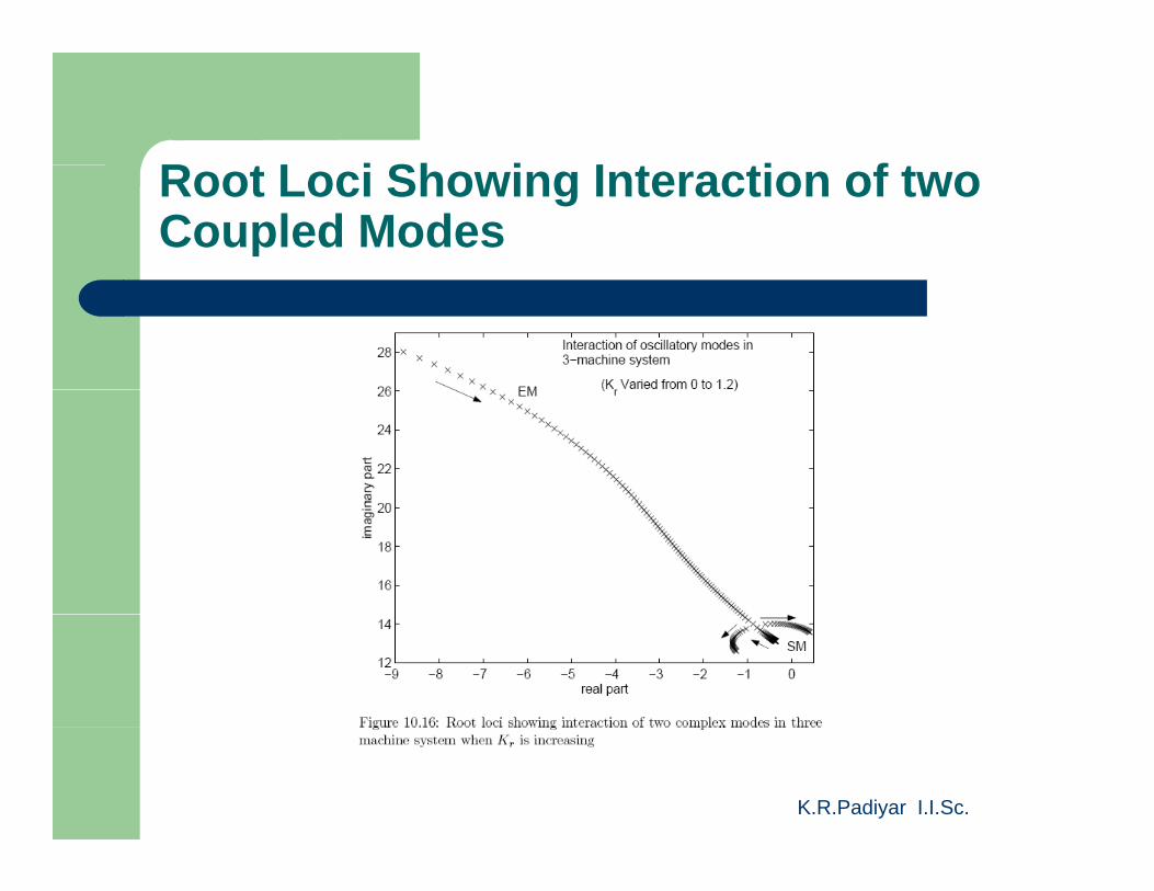
R t L i Sh i I t ti f tRoot Loci Showing Interaction of two Coupled Modes
K.R.Padiyar I.I.Sc.
An Example-Three Machine System
K.R.Padiyar I.I.Sc.
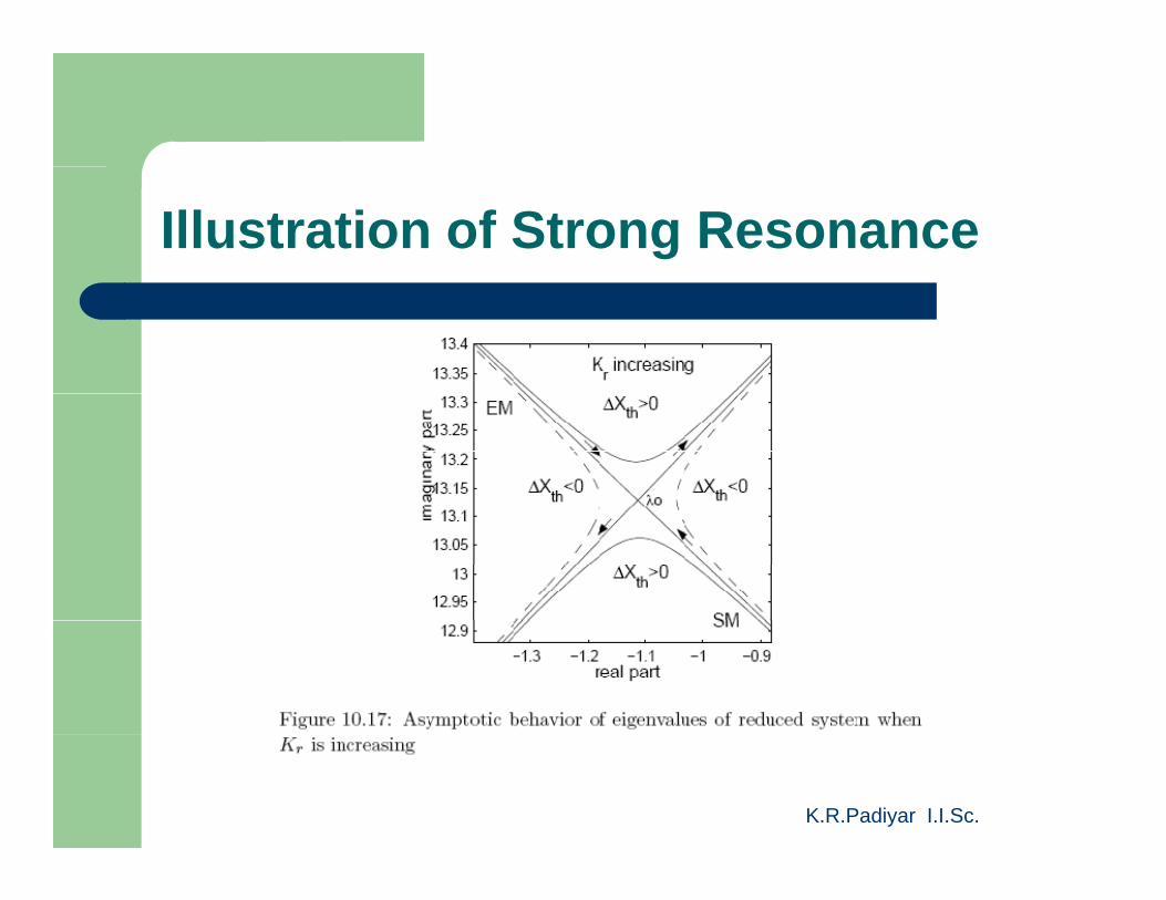
Illustration of Strong Resonance
K.R.Padiyar I.I.Sc.
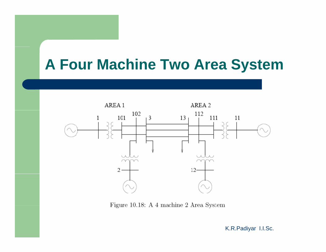
A Four Machine Two Area System
K.R.Padiyar I.I.Sc.

Bl k Di f UPFC M d l tiBlock Diagram of UPFC Modulation Controller
K.R.Padiyar I.I.Sc.
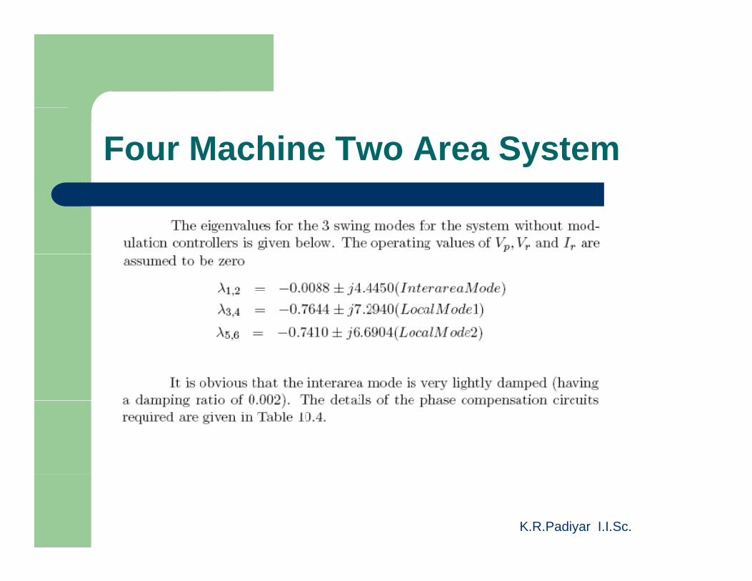
Four Machine Two Area System
K.R.Padiyar I.I.Sc.
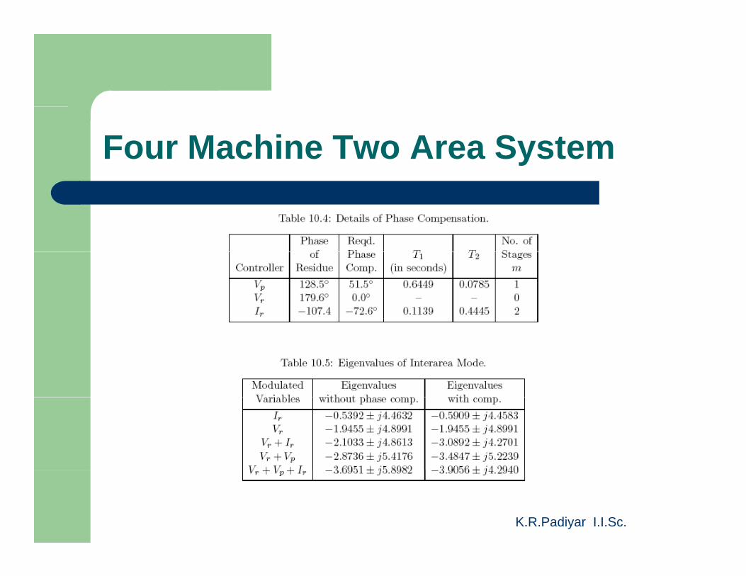
Four Machine Two Area System
K.R.Padiyar I.I.Sc.
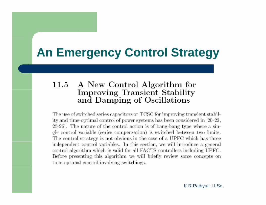
An Emergency Control Strategy
K.R.Padiyar I.I.Sc.
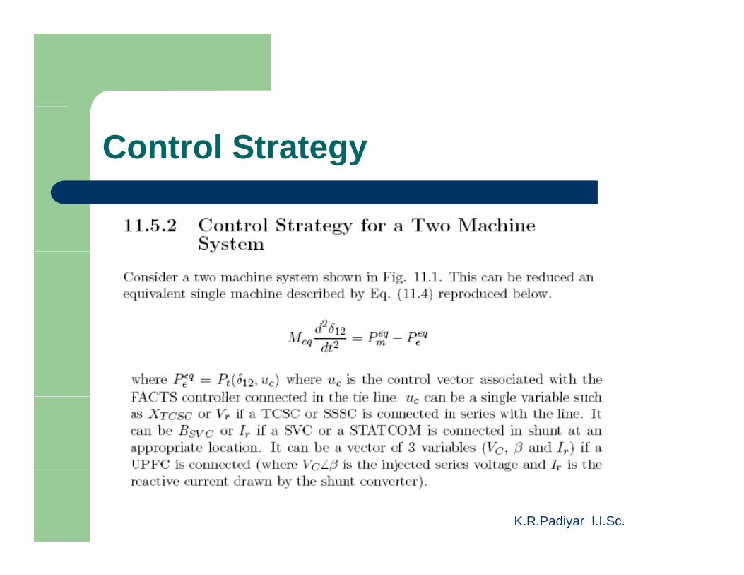
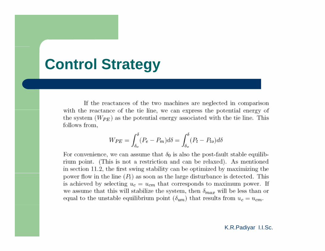
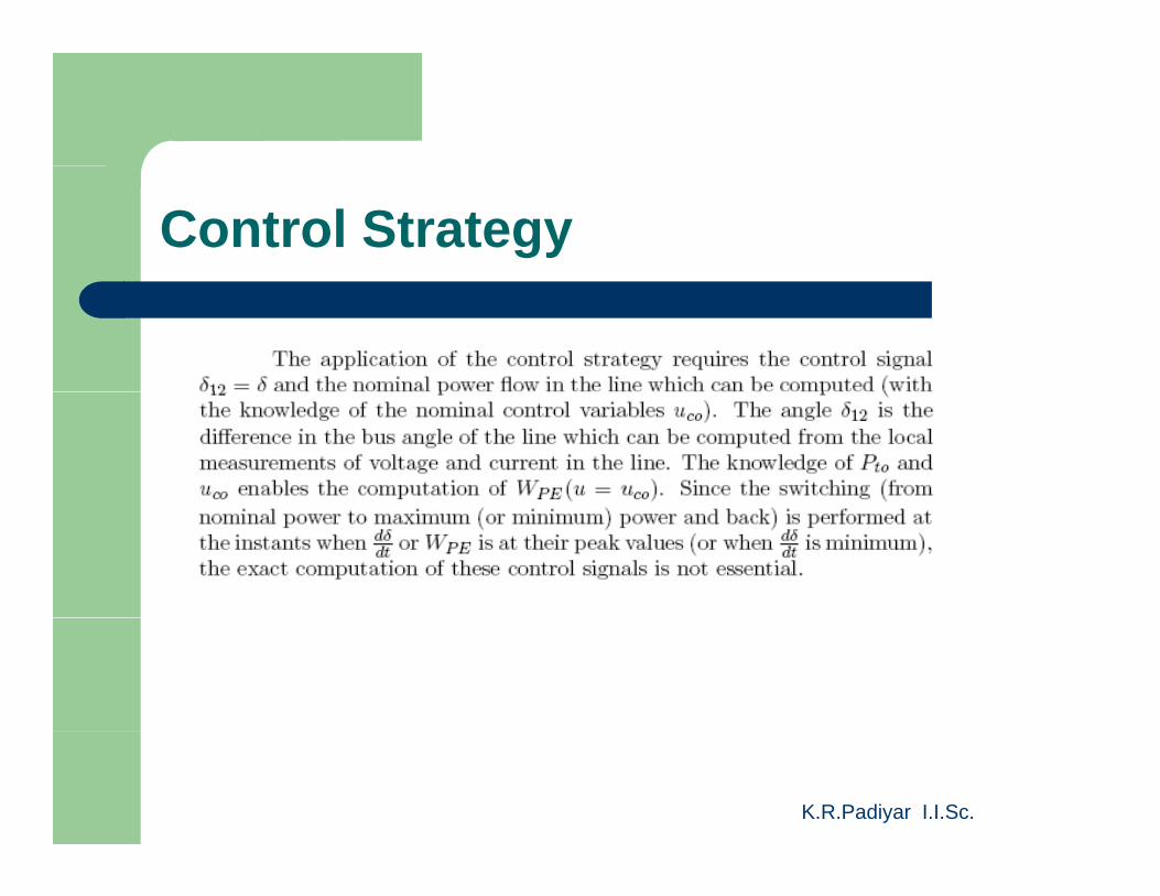
Control Strategy
K.R.Padiyar I.I.Sc.
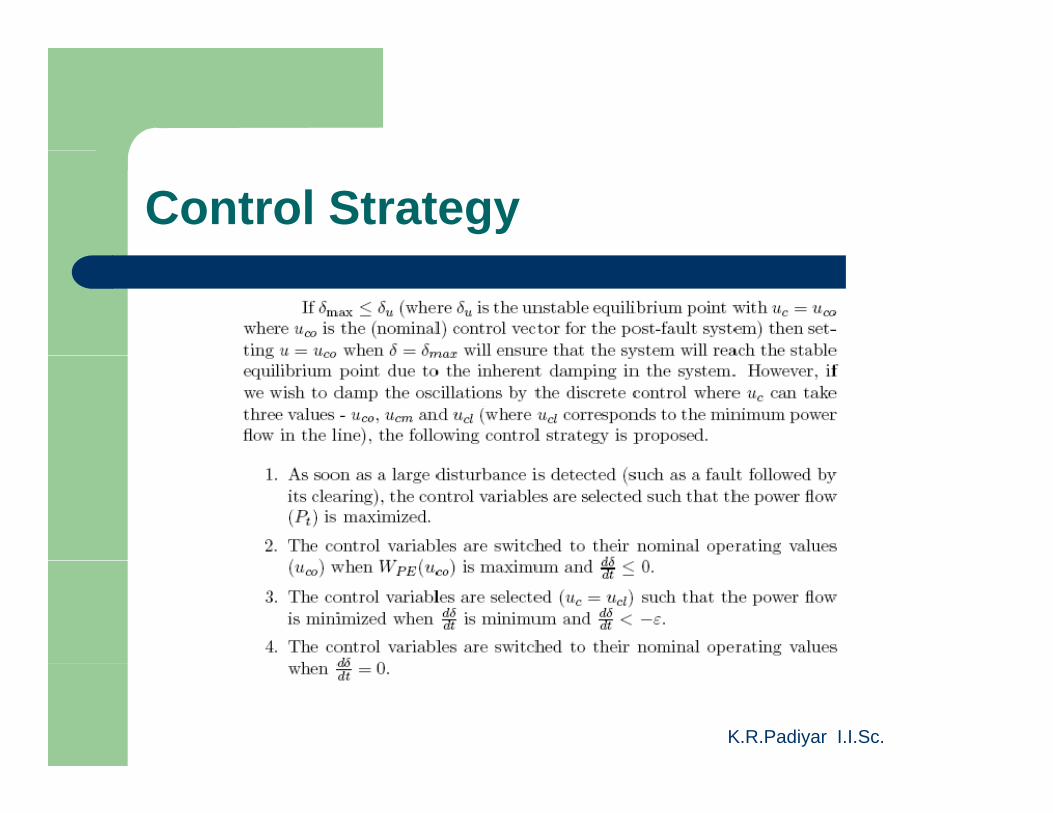
Control Strategy
K.R.Padiyar I.I.Sc.
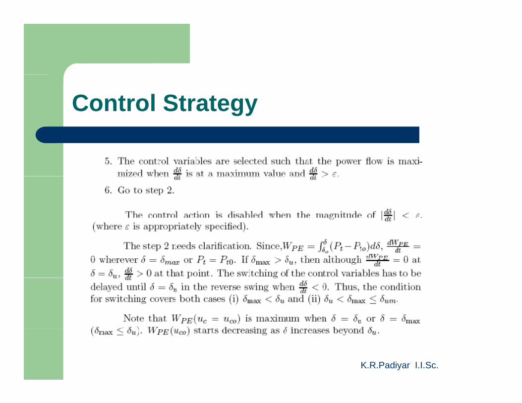
Control Strategy
K.R.Padiyar I.I.Sc.
Control Strategy
K.R.Padiyar I.I.Sc.
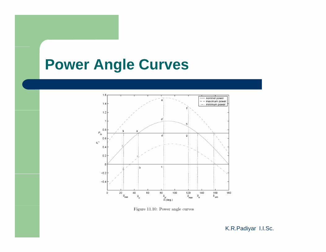
Power Angle Curves
K.R.Padiyar I.I.Sc.
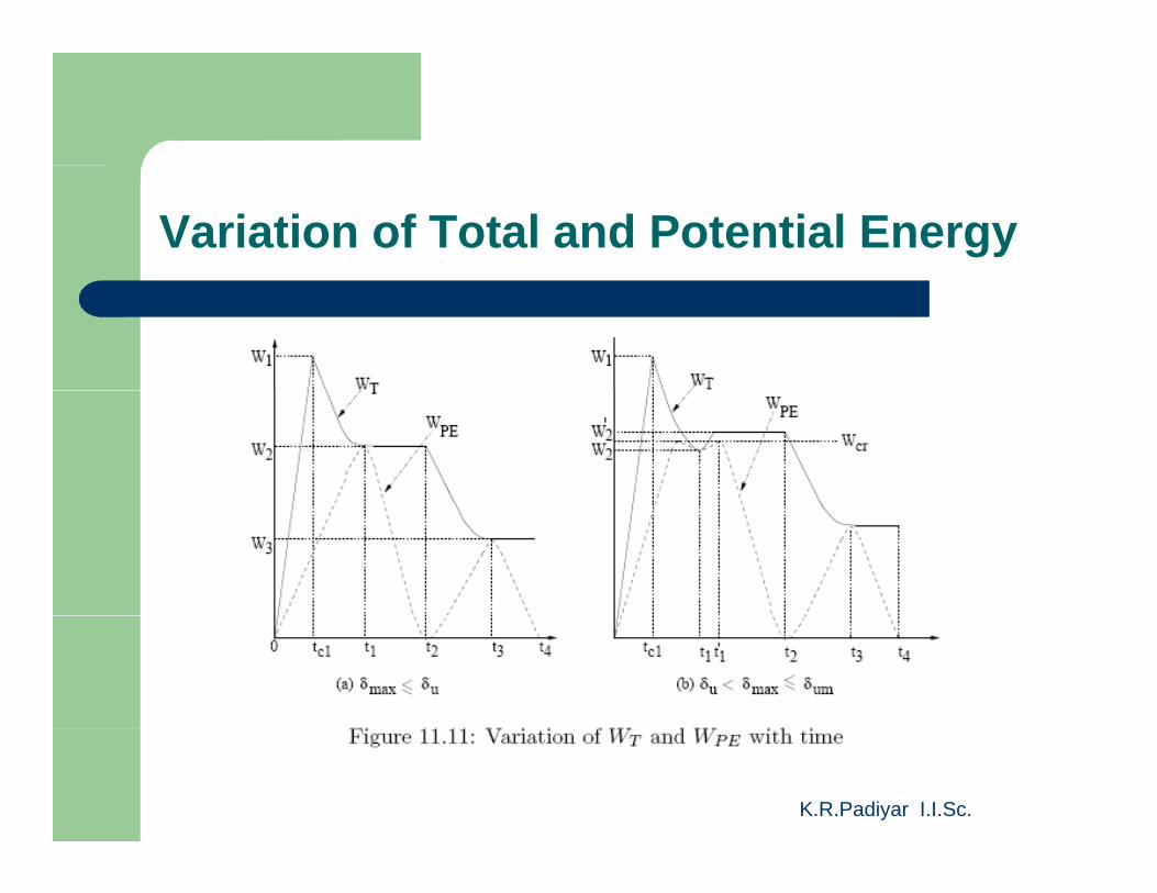
Variation of Total and Potential Energy
K.R.Padiyar I.I.Sc.
Control Strategy
K.R.Padiyar I.I.Sc.
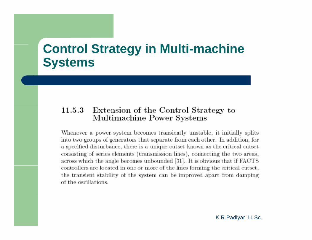
C t l St t i M lti hiControl Strategy in Multi-machine Systems
K.R.Padiyar I.I.Sc.
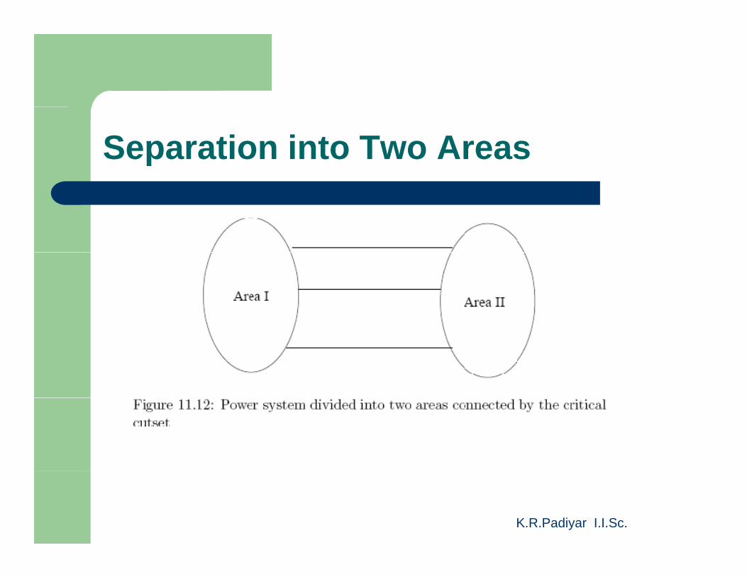
Separation into Two Areas
K.R.Padiyar I.I.Sc.
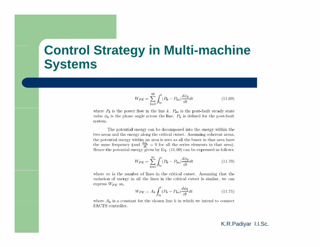
C t l St t i M lti hiControl Strategy in Multi-machine Systems
K.R.Padiyar I.I.Sc.
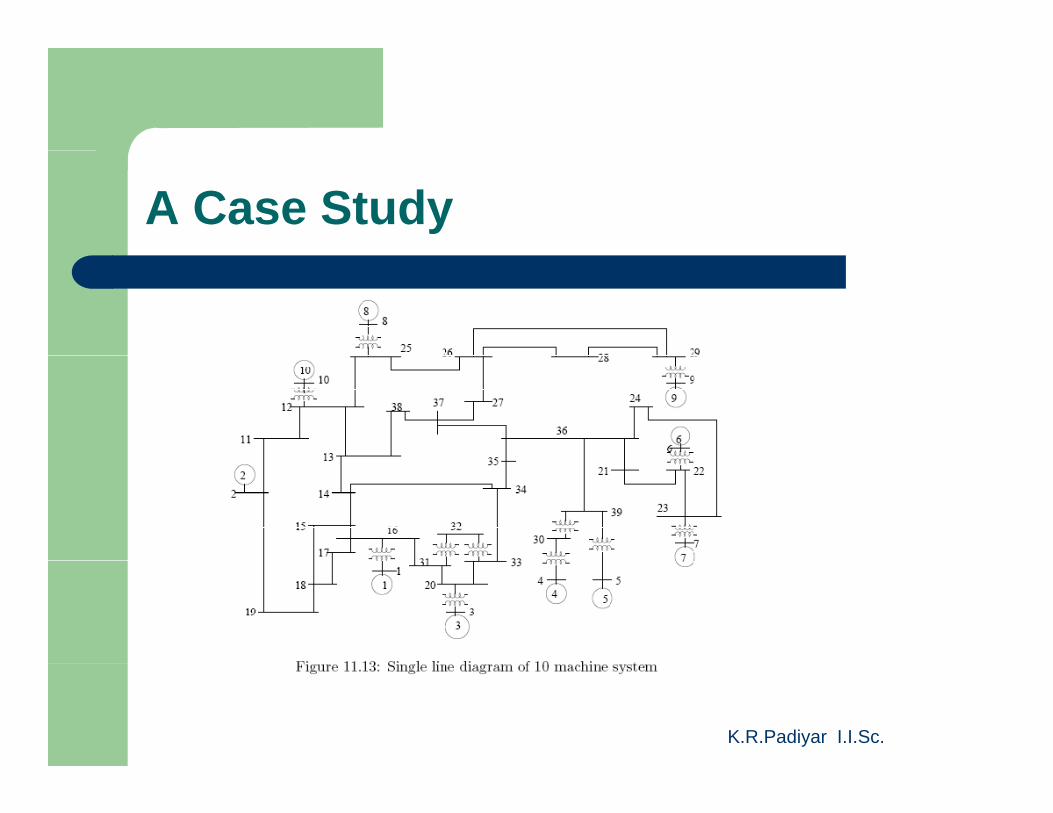
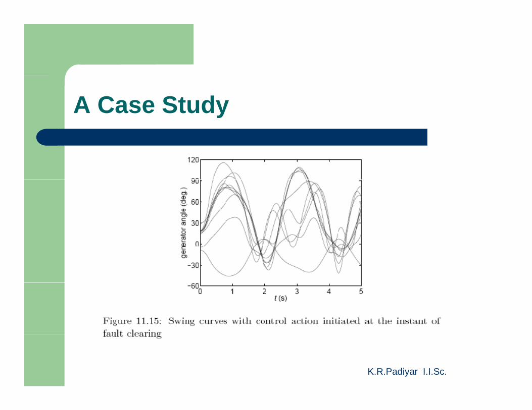
A Case Study
K.R.Padiyar I.I.Sc.
A Case Study
K.R.Padiyar I.I.Sc.
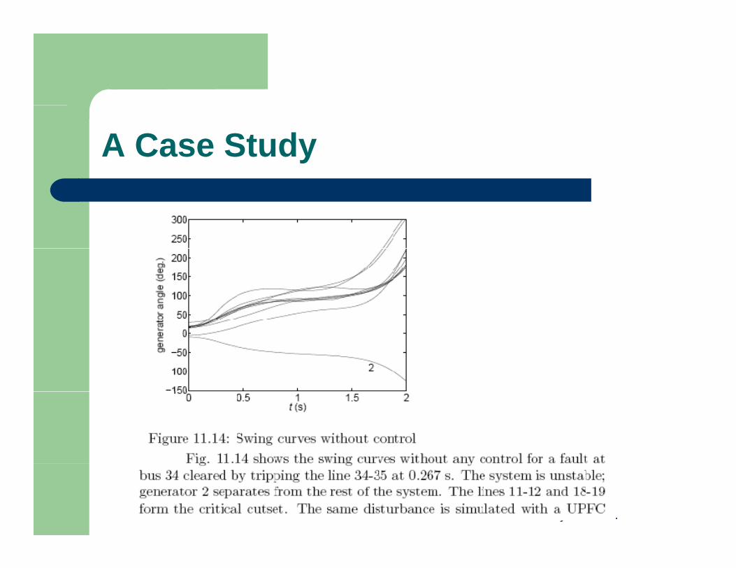
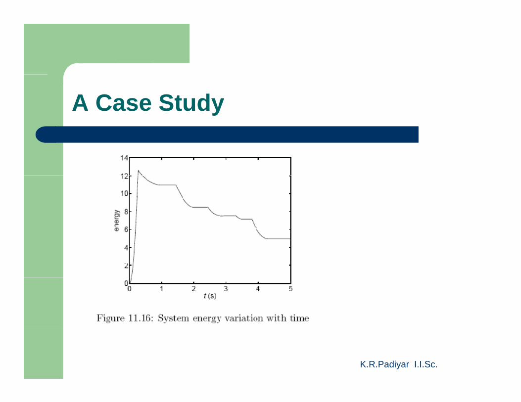
A Case Study
K.R.Padiyar I.I.Sc.
A Case Study
K.R.Padiyar I.I.Sc.
A Case Study
K.R.Padiyar I.I.Sc.
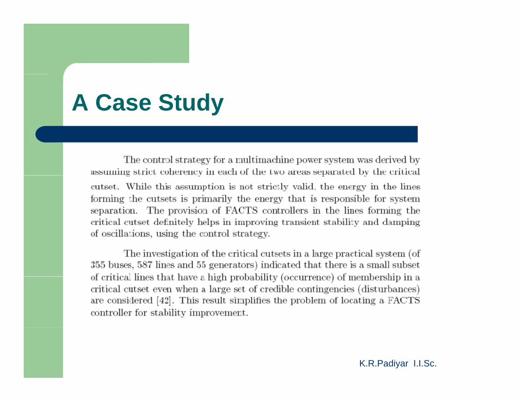
A Case Study
K.R.Padiyar I.I.Sc.
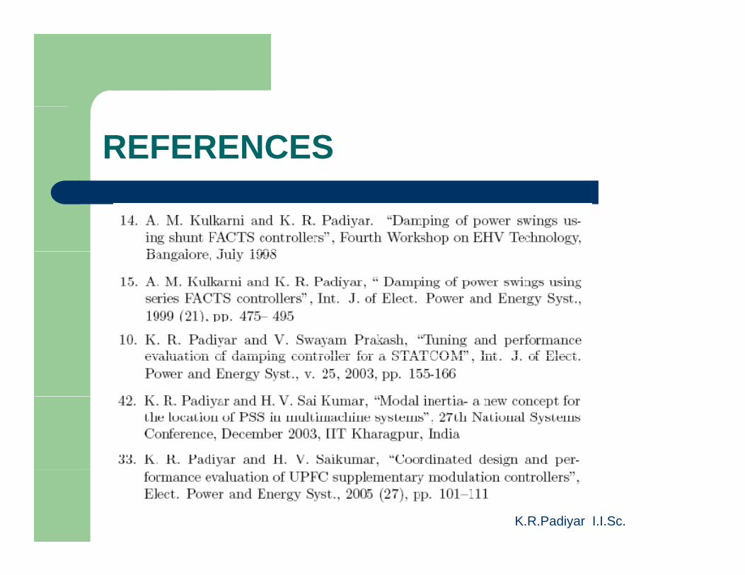
REFERENCES
K.R.Padiyar I.I.Sc.
REFERENCES
K.R.Padiyar I.I.Sc.


![A Fully Controllable Power System — Concept for FACTS … · arXiv:1506.08250v1 [cs.SY] 27 Jun 2015 1 A Fully Controllable Power System — Concept for FACTS and HVDC Placement](https://img.pdfslide.us/doc/110x75/5b71a15d7f8b9a740f8bc265/a-fully-controllable-power-system-concept-for-facts-arxiv150608250v1-cssy.jpg)