Embed Size (px)
Citation preview

ISSN: 2277-9655
[Pal* et al., 6(4): April, 2017] Impact Factor: 4.116
IC™ Value: 3.00 CODEN: IJESS7
http: // www.ijesrt.com © International Journal of Engineering Sciences & Research Technology
[156]
IJESRT INTERNATIONAL JOURNAL OF ENGINEERING SCIENCES & RESEARCH
TECHNOLOGY
CONTROL OF HYDROGEN ASSISTED CRACKING IN HIGH STRENGTH STEEL
WELDS Vinay Kumar Pal*, Dr. L. P. Singh, C.Pandey
* M. Tech, SHUATS, ALLAHABAD Department of Mechanical Engineering Sam Higginbottom
University of Agriculture, Technology And Sciences (U.P State Act No. 35of 2016, as passed by the
Uttar Pradesh Legislature) Allahabad, India
Assistant Professor, SHUATS, ALLAHABAD Department of Mechanical Engineering Sam
Higginbottom University of Agriculture, Technology And Sciences (U.P State Act No. 35of 2016, as
passed by the Uttar Pradesh Legislature) Allahabad, India
DOI: 10.5281/zenodo.557140
ABSTRACT In present research work, the modified Granjon implant test was performed to evaluate the susceptibility of AISI
8620 and AISI 304 steel towards the hydrogen assisted cracking (HAC). Glycerine methods was employed to
measure the diffusible hydrogen level (HD) in deposited metal for both the steels. The weld bead was deposited
by using the Shielded metal arc welding (SMAW) process with basic type electrodes. The hydrogen was
intentionally introduced for the plate of the material AISI 304 by using an oil of grade SAE 10, which is of very
low viscosity. The fractured and un-fractured implant assembly were examined by using the field-emission
scanning electron microscope (FESEM). The heat affected zone (HAZ) susceptibility is quantified by finding the
lower critical stress (LCS) for a measured hydrogen content. The exact location of the fractures varied according
to the type of materials being tested.
KEYWORDS: Hydrogen; HAC; LCS; CGHAZ; SMAW; Fracture.
INTRODUCTION Hydrogen in the weldments is still continues to be seriously limiting the performance of the compounds. A number
of intense research studies has have reported about the behaviour and effects of hydrogen in the steel and their
welds [1–5]. It is proven that a sufficient amount of hydrogen if present along with the susceptible microstructure
and the weld residual stress, poses a greater risk of hydrogen assisted cracking (HAC). It is very difficult to detect
the HAC in the weldments due to the fact that it occurs at the ambient temperature and also, it appears hours or
days after the completion of the welding. Therefore, even while in service it may cause the catastrophic failure of
the components [6,7]. Hydrogen embrittlement (HE) is used as the index of HAC in the weldments. Basically,
HE is a loss of mechanical properties caused due to the presence of hydrogen in atomic form and stress. The
hydrogen gas enters the arc atmosphere and hence, it also enters the solidifying weld region in arc welding process.
The risk of HAC depends on the crack susceptible microstructures, residual stress and the hydrogen content (HD)
in the deposited metals. The HAC is more significant in the ambient temperatures zone i.e. -50°C to 150°C. It is
often of delayed nature i.e. cracks can appear even after several days of the completion of the welding as it is
difficult to predict the HE. Usually, the hydrogen cracks are present either in HAZ or in weld metal itself, but it
is very difficult to predict the crack propagation behaviour. It is widely accepted that for HAC to take place, the
hydrogen content in the weld joint should be present along with the crack susceptible microstructure and tensile
residual stress, as shown in Fig. 1.

ISSN: 2277-9655
[Pal* et al., 6(4): April, 2017] Impact Factor: 4.116
IC™ Value: 3.00 CODEN: IJESS7
http: // www.ijesrt.com © International Journal of Engineering Sciences & Research Technology
[157]
Fig. 1 Three essential conditions to cause HAC[8]
For the low alloy steels the risk of HAC increases with the increasing hardness of the microstructure. The
microstructures developed in the weldments depends on the composition and the hardenability of the weld metal
and the parent metal, the cooling rate and the prior austenitic microstructure before transformation. Carbon
equivalent (CE) best describes the hardenability of the material. Higher the value of CE, higher will be the
hardenability which indicates higher tendency to form cracks. The HAZ closest to the fusion zone (coarse-grained
heat affected zone) transform to austenite as this region experiences the peak temperatures, and this austenitic
microstructure can get transformed to hard martensite or bainite due to rapid cooling after welding. It is to be
noted that due to the sufficiently high temperature coarse grain HAZ (CGHAZ) is formed which is more
hardenable and less ductile than the regions further away from the fusion zone and hence, there is a greater risk
of cracking in CGHAZ.
To determine the diffusible hydrogen content in the steel weldments, various methods has been developed and
successfully employed by the researchers [9–12]. The most commonly used methods are: Glycerine Method,
Mercury Method, Gas Chromatograph Method, and Hot Extraction Method. To estimate the hydrogen
embrittlement susceptibility, the common used method are: Implant tests, Lehigh Restraint Test, RPI Augmented
Strain Cracking Test, Controlled thermal severity (CTS) test and Lehigh Slot Weldability test [2,13]. In present
days, implant tests is most commonly used method to estimate the hydrogen embrittlement susceptibility. The
implant test, which was introduced by Henri Granjon at the Institute de Soudure (French Welding Institute) is an
externally loaded test used to determine the susceptibility of HAZ towards hydrogen assisted-cracking. During
implant test, a notched cylindrical specimen is prepared and inserted in the base plate of similar material, as shown
in Fig. 2. A weld bead is deposited over the specimen such that the top portion lie in the fusion zone and the notch
lie in the HAZ. After the completion of welding and before it becomes cold, a constant load is applied. The time
to failure is recorded and a plot is obtained for stress applied versus the time to failure. The threshold stress level
is hence determined which is called as lower critical stress (LCS).
Fig. 2 Schematic of implant test

ISSN: 2277-9655
[Pal* et al., 6(4): April, 2017] Impact Factor: 4.116
IC™ Value: 3.00 CODEN: IJESS7
http: // www.ijesrt.com © International Journal of Engineering Sciences & Research Technology
[158]
Hydrogen in the weldments of high strength steels continues to seriously limit the performance of the components
and confounds the quantitative component prognosis. Hydrogen is a transient element due to which it is difficult
to measure the exact hydrogen content in the steel. At a given temperature, the residual hydrogen remain trapped
and plays no role in HAC while the diffusible hydrogen is able to diffuse within or out of the weldment causes
HAC. It is therefore more study is required for the determination of the diffusible hydrogen content and the
fractography study is also required for the precise estimation of the behaviour of steel weldments under loading.
In present research work, the glycerin method is used for the diffusible hydrogen measurement in deposited metal
on high strength AISI 8620 and AISI 304 steel. Fabrication of implant testing set-up was done to quantify the
susceptibility of HAZ to HAC. The implant fracture specimen was also analysed to reveal the mode of fracture
by using the FE-SEM.
MATERIALS AND EXPERIMENTAL DETAILS Material and welding process parameters
High strength AISI 8620 and AISI 304 steel plate were used for the experiment. The chemical composition of
materials are given in Table 1. The mechanical properties of virgin steel are depicted in Table 2. The weld bead
was deposited by using the shielded metal arc welding process (SMAW). For both the material basic electrode
was used. The welding process parameters and electrode designation are given in Table 3.
Table 1 Chemical composition of AISI 8620 and AISI304, wt%
Material Element, wt%
AISI
8620
C Si Mn P S Cr Ni Fe Mo N
0.15 0.38 0.81 0.009 0.02 0.53 0.83 96.77 0.26 -
AISI304 0.07 0.49 1.62 0.008 0.026 17.74 9.77 70.11 - <0.005
Table 2 Mechanical properties of AISI 8620 and AISI304
Mechanical properties AISI 8620 AISI304
Tensile strength (MPa) 559 620
Yield strength (MPa) 394 288
Young’s modulus (GPa) 192 196
Vicker’s hardness (HV) 211 127
Table 3 Welding procedure and parameters used for AISI 8620 and AISI304
Welding conditions AISI 8620 AISI304
Welding process SMAW SMAW
Electrode type Basic electrode of AWS Code :
E7018-1
Basic electrode of AWS Code : E308-16
Electrode diameter 4 mm 4 mm
Electrode reconditioning Preheat at 100 °C for 4 hours Preheat at 100°C for 4 hours and then dipped in
oil (SAE 10 grade) for 30 min.
Voltage 25 V 25 V
Current 160 A 140 A
Travel speed 2.5 mm per sec 2.5 mm per sec
Implant tests
Implant testing allows evaluation of a material’s true heat-affected zone susceptibility to hydrogen induced
cracking. The implant tests was performed as per AWS standards (i.e. B4.0-98) and IIW guidelines. Test block
specimen, a small cylindrical specimen (implant specimen) is machined with a helical notch at one end and fit
into a hole drilled in a base metal specimen plate as per Table 4.

ISSN: 2277-9655
[Pal* et al., 6(4): April, 2017] Impact Factor: 4.116
IC™ Value: 3.00 CODEN: IJESS7
http: // www.ijesrt.com © International Journal of Engineering Sciences & Research Technology
[159]
Table 4 Dimensions of base plate and implant specimen
Base plate
Plate thickness 9.52 mm
Plate width 50.80 mm
Plate length 66.68 mm
Hole diameter at the centre 6.35 mm
Implant specimen
Total length (except gripping length) 41.27 mm
Gripping diameter 9.52 mm
Thread type ¼ - 28 UNF
Pitch 0.907 mm
Major diameter 6.35 mm
Minor diameter 5.24 mm
Thread length 9.52 mm
Thread angle 60 degrees
Thread root radius 0.1 Mm
As per pre-specified welding parameters a weld bead was deposited on the top surface of the specimen plate
directly over the threaded sample and hole, as shown in Fig. 3. The implant assembly was allowed to cool for 2
minutes at room temperature. After the cooling, the entire implant assembly was quenched in an alcohol ice bath
at 0°C until loading. Within 10 minutes after quenching the implant assembly was placed in the Universal Tensile
testing Machine (Instron 5982) and the desired test load is applied. After fracture of the specimen the load and
time to rupture was recorded. The experiment was repeated for number of specimens with different stress levels.
The maximum stress level sustained for a period of 24 hours was considered as lower critical stress (LCS). The
LCS is the threshold level of stress at which diffusible hydrogen even if present in sufficient amount for the crack
propagation it will not propagate.
Fig. 3 Implant test assembly
Diffusible hydrogen measurement
Glycerine test was used for measuring the mounts of diffusible hydrogen content present in the deposited metal
as per Indian standards IS 11802 (1986). Hydrogen specimens were prepared of 125 mm × 25 mm× 12 mm.
Glycerine test setup was turned on 4-5 hours prior to the actual test, as glycerine was to be maintained at 45°C
which require 4-5 hours for initial test. Single weld bead was deposited on 25 mm surface of 100 mm in length
with same welding parameters as used in depositing bead on the implant assembly. Immediately after the bead
deposition specimen were quenched in water at 20 °C for 30 s. After quenching specimen was stored in dry ice or
liquid nitrogen until measurement. After that, specimen was introduced in an apparatus containing glycerine which

ISSN: 2277-9655
[Pal* et al., 6(4): April, 2017] Impact Factor: 4.116
IC™ Value: 3.00 CODEN: IJESS7
http: // www.ijesrt.com © International Journal of Engineering Sciences & Research Technology
[160]
was maintained at 45 °C. Hydrogen was collected from the deposited metal for 48 hours. The glycerine set-up is
shown in Fig. 4(a). The test specimen is shown in Fig. 4(b).
Fig. 4 (a) Glycerine test setup, (b) Glycerine test specimen
The average estimated (HD) was estimated by using the following relation;
g
ml
WW
P
TVH
if
tGlycerine100
)100
)(760
)(273
273(
(1)
where, HGlycerine is diffusible hydrogen measured, Vt is volume of hydrogen measured at temperature T and
pressure P, Wi is weight of specimen before welding and Wf is weight of specimen after removal from the glycerine
apparatus.
Microstructure characterization and hardness measurement
The unfractured implant specimen was sectioned with help of wire EDM perpendicular to the welding direction
through the axis of the implant specimens. The sample was grinded and polished by using the SiC emery paper
upto grit size of 2000. After the paper polishing, the sample was etched in 5 % Nital solution for 60 s. the
microstructure characterization was carried out by using the field-emission scanning electron microscope and
optical microscope.
Fig. 5 Typical implant test specimen sectioned near the implant axis for AISI 8620, 5% nital etch

ISSN: 2277-9655
[Pal* et al., 6(4): April, 2017] Impact Factor: 4.116
IC™ Value: 3.00 CODEN: IJESS7
http: // www.ijesrt.com © International Journal of Engineering Sciences & Research Technology
[161]
Microhardness was recorded along the XY axis (implant axis) of unfractured sample, as shown in Fig. 5. The
microhardness was recorded at load of 500 g with dwell time of 10 s. To examine the mode of fracture and relative
amounts of each mode of fracture, the implant fracture surface was also examined by using the FESEM.
RESULTS AND DISCUSSION Diffusible hydrogen content
The amount of diffusible hydrogen content was measured at T= 27 °C and P=760 mm for four specimens of AISI
8620 by Glycerine test and the average estimated (𝐻𝐺𝐿𝑌𝐶𝐸𝑅𝐼𝑁) is corrected for STP which was calculated close to
4.62 ml per 100 g, whereas for the second case i.e. AISI 304, the average estimated (𝐻𝐺𝐿𝑌𝐶𝐸𝑅𝐼𝑁) is corrected for
STP which was calculated close to 9.48 ml per 100 g. This is due to the contamination of the electrodes with
hydrocarbons for the 304 grade stainless steel. The increased level of hydrogen in AISI 304 was due to the pickup
of oil in the electrodes while being dipped. It has been reviewed in recent research that the hydrogen embrittlement
is more significant for the case where the HD content is found to be more than 5 ml per 100g. Here, it can be
observed with the AISI 304. The results of diffusible hydrogen measurement is depicted in Table 5.
Table 5 Diffusible hydrogen level content in deposited metal for AISI 304 and AISI 8620 steel
Weld type Diffusible hydrogen content
(HGlycerine) (ml/100gm)
Mean diffusible
hydrogen content
(HGlycerine)
(ml/100gm)
Standard deviation for
HGlycerine measurement
Trial 1 Trial 2 Trial 3
AISI 8620 4.58 4.65 4.62 4.62 0.035
AISI 304 9.4 9.45 9.60 9.48 0.104
Microhardness
The data obtained from Vickers hardness test is used to plot as shown in Fig. 6(a-b). the microhardness reading
are taken along the implant axis for both the steels, as shown in Fig. 5. Varation in hardness value across the
deposited metal (weld fusion zone and HAZs) reveals the present of hetrogenious microstructure. For AISI 8620
steel, the hardness in weld fusion zone varied from 220-229 HV while, in AISI 304 varied from 233-265 HV.
Maximum hardness value is noticed in CGHAZ for both the steels. The CGHAZ hardness was measured to be
298 HV and 301 HV for AISI 8620 and AISI 304, respectively. The CGHAZ hardness value are much higher than
their respective BM hardness. That means the CGHAZ has a higher tensile strength than that of the base metal for
the two steels. The higher strength and hardness of CGHAZ make it more susceptible for HAC. The hardness
variation occurs due to the change of microstructures. The microstructures gets varied due to the different level
and type of heat involved while and at the end of completion of welding. The lower hardness was measured in
soft inter-critical heat affected zone (IC-HAZ), as shown in Fig. 6.

ISSN: 2277-9655
[Pal* et al., 6(4): April, 2017] Impact Factor: 4.116
IC™ Value: 3.00 CODEN: IJESS7
http: // www.ijesrt.com © International Journal of Engineering Sciences & Research Technology
[162]
Fig. 6 Vickers hardness versus the distance taken along the axis of the implant specimen; (a) For the
material AISI 8620, and (b) For the material AISI 304
Lower critical stress
The data obtained from the implant testing is used to draw plot of applied stress versus time to rupture for each
specimen, as shown in Fig. 7(a-b).
Fig. 7 Stress versus time to failure; (a) For the material AISI 8620, and (b) For the material AISI 304
The implant test results are depicted in Table 6. The Table 6 consisted of following terms;
(a) The microhardness value of CGHAZ was converted to CGHAZ tensile strength by using the hardness
conversion chart for both the steel.
(b) The embrittlement index of steels was represented as the ratio of LCS to tensile strength of CGHAZ.
Table 6 Implant test results
Experiment Case Diffusible
hydrogen content
(ml/100 gm)
CGHAZ Max
Hardness (HV)
CGHAZ
tensile strength
(MPa)
Lower
critical stress
(MPa)
Embrittlement index
AISI 8620 4.62 298 965 525 0.54
AISI 304 9.48 301 975 448 0.45
The embrittlement index (EI) of AISI 8620 is close to 0.54 whereas embrittlement index for AISI 304 was found
close to 0.45. The decrease in the value of embrittlement index was the result of introduced HD in the deposited
metal of AISI 304. The electrode being contaminated with lubricating oil of grade SAE 10 resulted in the pickup
of hydrogen in the welds of AISI 304. The electrode used for AISI 8620 was not contaminated with any kind of
oil and hence, very less introduction of hydrocarbons. It is to be noted that lower value for the embrittlement index
in particular material indicate increased susceptibility to hydrogen embrittlement. The EI mainly depend on the
LCS value because the CGHAZ hardness does not show a significant variation. High EI value indicates the better
performance of material in the weld condition. The CGHAZ strength after conversion was 965 MPa and 975 MPa
for AISI 8620 and AISI 304 steel, respectively. Hence, result showed that AISI 8620 steel have less susceptibility
to HAZ HAC compared to AISI 304 steel.
Metallographic examination
The optical micrographs were taken for study of microstructures from unfractured specimens near the LCS. Note
that the HAZ in the implant specimen is much wider than that in the adjacent plate as shown in Fig. 5, due to the
ISSN: 2277-9655
[Pal* et al., 6(4): April, 2017] Impact Factor: 4.116
IC™ Value: 3.00 CODEN: IJESS7
http: // www.ijesrt.com © International Journal of Engineering Sciences & Research Technology
[163]
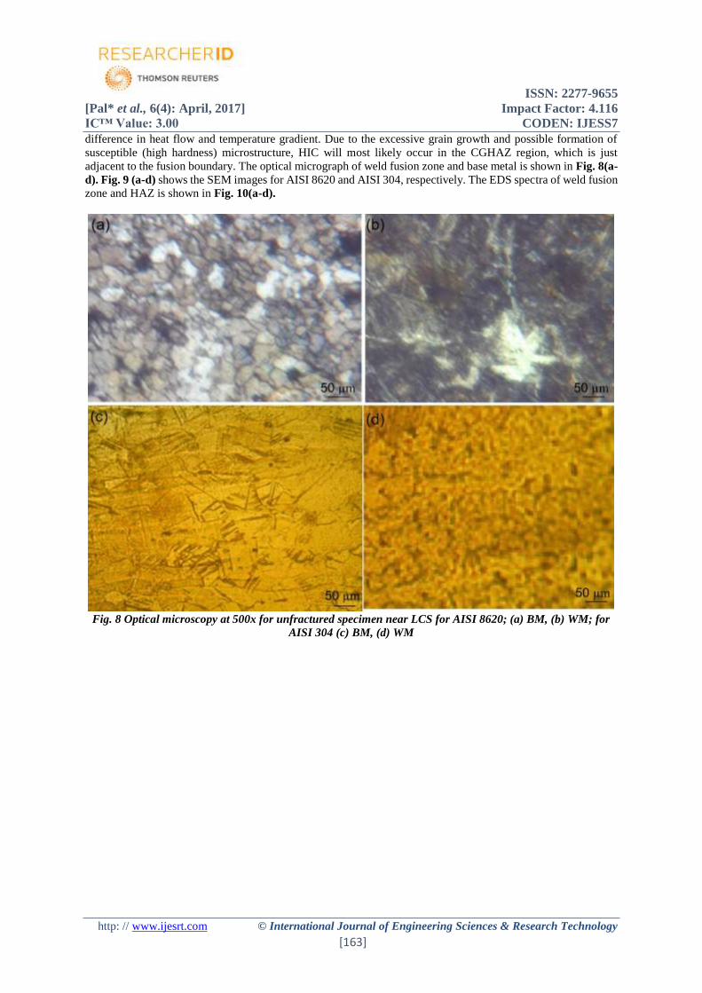
difference in heat flow and temperature gradient. Due to the excessive grain growth and possible formation of
susceptible (high hardness) microstructure, HIC will most likely occur in the CGHAZ region, which is just
adjacent to the fusion boundary. The optical micrograph of weld fusion zone and base metal is shown in Fig. 8(a-
d). Fig. 9 (a-d) shows the SEM images for AISI 8620 and AISI 304, respectively. The EDS spectra of weld fusion
zone and HAZ is shown in Fig. 10(a-d).
Fig. 8 Optical microscopy at 500x for unfractured specimen near LCS for AISI 8620; (a) BM, (b) WM; for
AISI 304 (c) BM, (d) WM

ISSN: 2277-9655
[Pal* et al., 6(4): April, 2017] Impact Factor: 4.116
IC™ Value: 3.00 CODEN: IJESS7
http: // www.ijesrt.com © International Journal of Engineering Sciences & Research Technology
[164]
Fig. 9 Microstructures observed under SEM for unfractured specimen near LCS for AISI 8620 (a) BM, (b)
WM; for AISI 304 (c) BM, (d) WM
Fig. 10 EDAX for unfractured specimen near LCS for AISI 8620 for the region (a) weld zone, (b) HAZ;
AISI 304 for region (c) weld zone, (d) HAZ

ISSN: 2277-9655
[Pal* et al., 6(4): April, 2017] Impact Factor: 4.116
IC™ Value: 3.00 CODEN: IJESS7
http: // www.ijesrt.com © International Journal of Engineering Sciences & Research Technology
[165]
Fracture surface morphology
Fig. 11 shows the fracture morphology of implant tested specimen of the material AISI 8620. It can be observed
that final fracture occurred in mixed mode. The top view of fracture surface indicates the intergranular (IG) mode
of fracture, as shown in Fig. 11(a). The cleavage facets are clearly seen in the crack initiation zone, as shown in
Fig. 11(b). The presence of cleavage facet signifies the brittle mode of fracture in some regions. As the crack
propagates, the quasi-cleavage (QC) mode of fracture is noticed, as shown in Fig. 11(c). In final fracture zone,
the microvoid coalescence (MVC) is noticed, as shown in Fig. 11(d-e). The presence of dimples signifies the
ductile mode of fracture. The region of dimples is more as compared with cleavage facet. Therefore, it can be
concluded that the ductile mode of fracture is dominant and the fracture occurred in mixed mode i.e. ductile in
some regions as well as brittle in some regions.
Fig. 11 Fracture morphology of AISI 8620 implant specimen; (a) Top-view of fracture surface, crack
initiation zone (b) cleavage and dimples (c) final fracture zone (mixed mode), (d) microvoid coalescence
ISSN: 2277-9655
[Pal* et al., 6(4): April, 2017] Impact Factor: 4.116
IC™ Value: 3.00 CODEN: IJESS7
http: // www.ijesrt.com © International Journal of Engineering Sciences & Research Technology
[166]
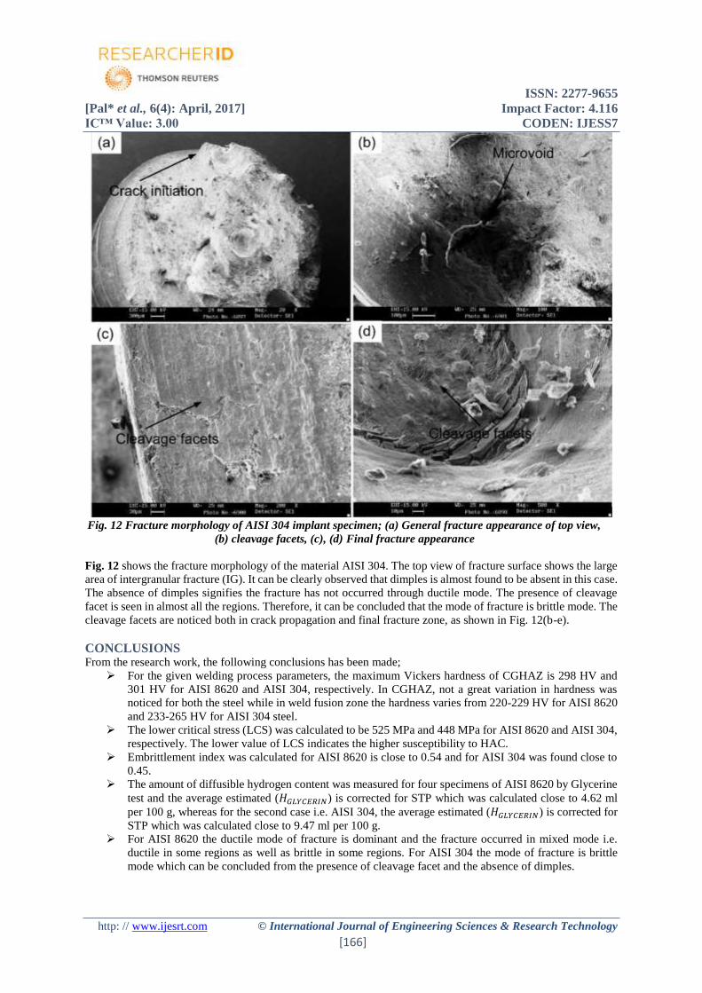
Fig. 12 Fracture morphology of AISI 304 implant specimen; (a) General fracture appearance of top view,
(b) cleavage facets, (c), (d) Final fracture appearance
Fig. 12 shows the fracture morphology of the material AISI 304. The top view of fracture surface shows the large
area of intergranular fracture (IG). It can be clearly observed that dimples is almost found to be absent in this case.
The absence of dimples signifies the fracture has not occurred through ductile mode. The presence of cleavage
facet is seen in almost all the regions. Therefore, it can be concluded that the mode of fracture is brittle mode. The
cleavage facets are noticed both in crack propagation and final fracture zone, as shown in Fig. 12(b-e).
CONCLUSIONS From the research work, the following conclusions has been made;
For the given welding process parameters, the maximum Vickers hardness of CGHAZ is 298 HV and
301 HV for AISI 8620 and AISI 304, respectively. In CGHAZ, not a great variation in hardness was
noticed for both the steel while in weld fusion zone the hardness varies from 220-229 HV for AISI 8620
and 233-265 HV for AISI 304 steel.
The lower critical stress (LCS) was calculated to be 525 MPa and 448 MPa for AISI 8620 and AISI 304,
respectively. The lower value of LCS indicates the higher susceptibility to HAC.
Embrittlement index was calculated for AISI 8620 is close to 0.54 and for AISI 304 was found close to
0.45.
The amount of diffusible hydrogen content was measured for four specimens of AISI 8620 by Glycerine
test and the average estimated (𝐻𝐺𝐿𝑌𝐶𝐸𝑅𝐼𝑁) is corrected for STP which was calculated close to 4.62 ml
per 100 g, whereas for the second case i.e. AISI 304, the average estimated (𝐻𝐺𝐿𝑌𝐶𝐸𝑅𝐼𝑁) is corrected for
STP which was calculated close to 9.47 ml per 100 g.
For AISI 8620 the ductile mode of fracture is dominant and the fracture occurred in mixed mode i.e.
ductile in some regions as well as brittle in some regions. For AISI 304 the mode of fracture is brittle
mode which can be concluded from the presence of cleavage facet and the absence of dimples.

ISSN: 2277-9655
[Pal* et al., 6(4): April, 2017] Impact Factor: 4.116
IC™ Value: 3.00 CODEN: IJESS7
http: // www.ijesrt.com © International Journal of Engineering Sciences & Research Technology
[167]
REFERENCES [1] X. L. Feng and J. C. Lippold, 265 (n.d.).
[2] C. Pandey, N. Saini, M. M. Mahapatra, and P. Kumar, Int. J. Hydrogen Energy (2016).
[3] C. Pandey, M. M. Mahapatra, P. Kumar, and N. Saini, J. Eng. Mater. Technol. (2017).
[4] M. Glicerynową, 39, 47 (2013).
[5] G. Magudeeswaran, V. Balasubramanian, and G. Madhusudhan Reddy, Int. J. Hydrogen Energy 33, 1897
(2008).
[6] X. Yue, Weld. World 59, 77 (2014).
[7] A. W. Vasudevan, R. Stout, R. D. Pense, Weld. J. 60, 155 (1981).
[8] P. G. Kumar and K. Yu-ichi, Trans. JWRI 42, 39 (2013).
[9] D. Fydrych, A. ??wierczynska, and G. Rogalski, Metall. Ital. 107, 47 (2015).
[10] D. Fydrych and G. Rogalski, Weld. Int. 25, 166 (2011).
[11] D. Fydrych and J. Łabanowski, (2015).
[12] G. K. Padhy, V. Ramasubbu, and S. K. Albert, J. Test. Eval. 43, (2015).
[13] B. Y. W. P. Campbell, (n.d.).


![Hydrogen environmentally assisted cracking during static loading … · problem affecting many high strength engineering alloys including steels [1], β-Ti alloys [2] and aluminium](https://img.pdfslide.us/doc/110x75/60e78d786a8326072a164dd6/hydrogen-environmentally-assisted-cracking-during-static-loading-problem-affecting.jpg)