Embed Size (px)
Citation preview
CONTROL INTERFACE AND FUNCTIONALITY OF TPS
BOOSTER POWER SUPPLY
C. Y. Wu, P. C. Chiu, Y. S. Cheng, C. Y. Liao, Jenny Chen, Demi Lee, C. H. Huang, K. H.
Hu, K. T. Hsu
NSRRC, Hsinchu 30076, Taiwan
Abstract
The TPS booster is a synchrotron with injection
energy at 150 MeV and extraction energy at 3 GeV in 3
Hz. Booster main power supplies consist of one dipole
power supply with maximum current 1200 Ampere and
four quadrupole family power supplies with maximum
current of 120/150 Ampere. The small power supply for
booster corrector and sextupole is a low noise switching
power supply with +/- 10 Ampere current range. The TPS
booster control environment is based on EPICS
framework to support rich functionalities including power
supply control, waveform management, operation
supports, and so on. All power supplies support DC mode
and 3 Hz ramping mode operation for TPS booster
commissioning and operation. Efforts on control interface
and functionality for TPS booster power supply will be
summarizes.
INTRODUCTION
The TPS [1] is a latest generation of high brightness
synchrotron light source which had completed phase I
commissioning in March, 2015 [2-3]. It consists of a 150
MeV electron Linac, a 3 GeV booster synchrotron, and a
3 GeV storage ring. The EPICS (Experimental Physics
and Industrial Control System) was chosen for the TPS
accelerator control.
The control interfaces of TPS booster power supplies
have two major categories: one is for the large main
power supply which could provide current up to 1200 and
120/150 amperes and used for dipole magnets and
quadrupole magnets respectively; the other is small power
supply which supports +/- 10 Amperes current output and
used for sextupole magnets and correctors. Table 1
summarizes the specifications of booster ring power
supplies [4-5].
Table 1: TPS Booster Ring Power Supply Summary
Magnet Type Max
Current
Number
of PS PS Vendor Control Interface
Dipole Unipolar 1200 A 1 Eaton[4]
RS485 &
Analog interface
Quadrupole Unipolar 120/150 A 4~5 Eaton RS485 &
Analog interface
Sextupole Bipolar ± 10 A 4 ITRI [5] Analog interface
Corrector Bipolar ± 10 A HC: 60
VC: 36 ITRI
CPSC
(Ethernet)
All of these power supplies should have features of
waveform play with external trigger functionalities to
enable electron beams ramp from 150 MeV to 3 GeV in 3
Hz. The large power supply provides RS-485 control
interface for ON/OFF and status reading and analog input
for current setting. One dedicated EPICS IOC is used to
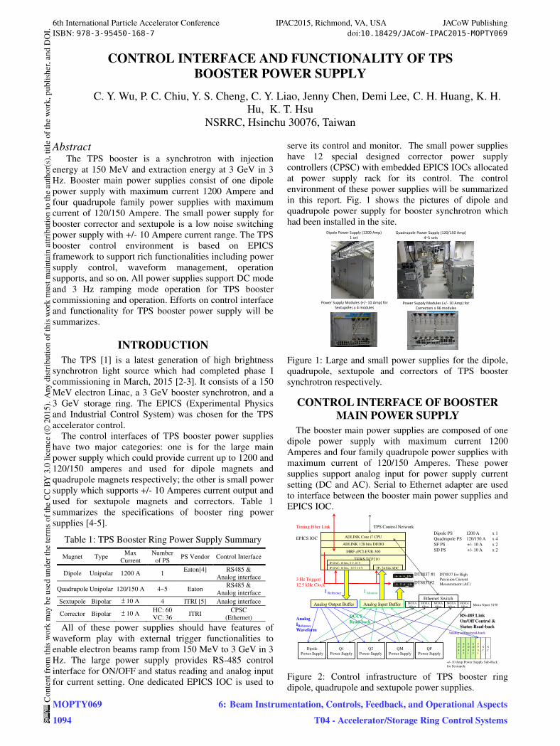
serve its control and monitor. The small power supplies
have 12 special designed corrector power supply
controllers (CPSC) with embedded EPICS IOCs allocated
at power supply rack for its control. The control
environment of these power supplies will be summarized
in this report. Fig. 1 shows the pictures of dipole and
quadrupole power supply for booster synchrotron which
had been installed in the site. Dipole Power Supply (1200 Amp)
1 set
Quadrupole Power Supply (120/150 Amp)
4~5 sets
Power Supply Modules (+/- 10 Amp) for
Correctors x 96 modules
Power Supply Modules (+/- 10 Amp) for
Sextupoles x 4 modules
Figure 1: Large and small power supplies for the dipole,
quadrupole, sextupole and correctors of TPS booster
synchrotron respectively.
CONTROL INTERFACE OF BOOSTER
MAIN POWER SUPPLY
The booster main power supplies are composed of one
dipole power supply with maximum current 1200
Amperes and four family quadrupole power supplies with
maximum current of 120/150 Amperes. These power
supplies support analog input for power supply current
setting (DC and AC). Serial to Ethernet adapter are used
to interface between the booster main power supplies and
EPICS IOC.
ADLINK 128 bits DI/DO
ADLINK Core i7 CPU
MRF cPCI-EVR-300
EPICS IOC
Ethernet Switch
TPS Control Network
I Monitor
3 Hz Trigger/
12.5 kHz Clock
Analog
IReference
Waveform
Dipole PS 1200 A x 1
Quadrupole PS 120/150 A x 4
SF PS +/- 10 A x 2
SD PS +/- 10 A x 2
C
P
S
I
S
F
#
1
S
F
#
2
S
D
#
1
S
D
#
2
N
C
Analog setting/read-back
Q1
Power Supply
Q2
Power Supply
QM
Power Supply
QF
Power Supply
Analog Output Buffer Analog Input Buffer
I Reference
DCCT
Read-back
Timing Fiber Link
DT8837 #1
DT8837#2
RS-485 Link
On/Off Control &
Status Read-back
TEWS TCP210
IP- 24 bits ADC
IP DAC- 18 bits, 0 V-10 V
Dipole
Power Supply
MOXA
NPort
MOXA
NPort
MOXA
NPort
MOXA
NPort
MOXA
NPortMoxa Nport 5150
IP DAC- 18 bits, -10 V-10 V
N
C
+/- 10 Amp Power Supply Sub-Rack
for Sextupole
DT8837 for High
Precision Current
Measurement (AC)
Figure 2: Control infrastructure of TPS booster ring
dipole, quadrupole and sextupole power supplies.
6th International Particle Accelerator Conference IPAC2015, Richmond, VA, USA JACoW PublishingISBN: 978-3-95450-168-7 doi:10.18429/JACoW-IPAC2015-MOPTY069
MOPTY0691094
Cont
entf
rom
this
wor
km
aybe
used
unde
rthe
term
soft
heCC
BY3.
0lic
ence
(©20
15).
Any
distr
ibut
ion
ofth
isw
ork
mus
tmai
ntai
nat
tribu
tion
toth
eau
thor
(s),
title
ofth
ew
ork,
publ
isher
,and
DO
I.
6: Beam Instrumentation, Controls, Feedback, and Operational AspectsT04 - Accelerator/Storage Ring Control Systems
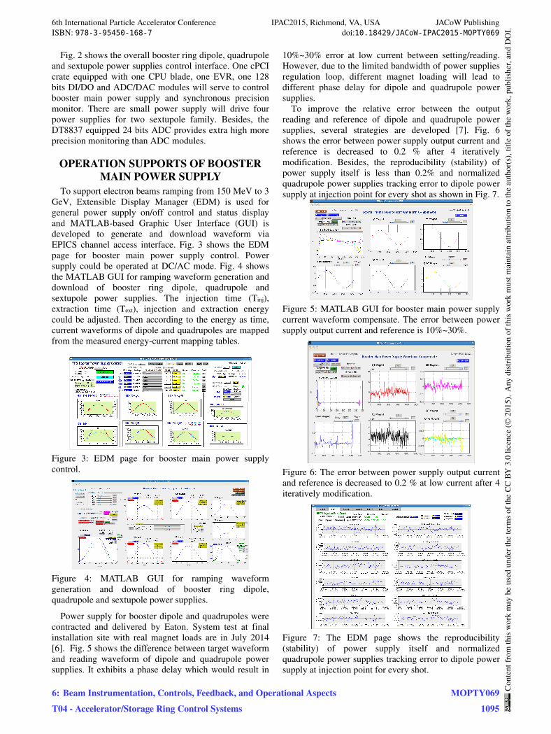
Fig. 2 shows the overall booster ring dipole, quadrupole
and sextupole power supplies control interface. One cPCI
crate equipped with one CPU blade, one EVR, one 128
bits DI/DO and ADC/DAC modules will serve to control
booster main power supply and synchronous precision
monitor. There are small power supply will drive four
power supplies for two sextupole family. Besides, the
DT8837 equipped 24 bits ADC provides extra high more
precision monitoring than ADC modules.
OPERATION SUPPORTS OF BOOSTER
MAIN POWER SUPPLY
To support electron beams ramping from 150 MeV to 3
GeV, Extensible Display Manager (EDM) is used for
general power supply on/off control and status display
and MATLAB-based Graphic User Interface (GUI) is
developed to generate and download waveform via
EPICS channel access interface. Fig. 3 shows the EDM
page for booster main power supply control. Power
supply could be operated at DC/AC mode. Fig. 4 shows
the MATLAB GUI for ramping waveform generation and
download of booster ring dipole, quadrupole and
sextupole power supplies. The injection time (Tinj),
extraction time (Text), injection and extraction energy
could be adjusted. Then according to the energy as time,
current waveforms of dipole and quadrupoles are mapped
from the measured energy-current mapping tables.
Figure 3: EDM page for booster main power supply
control.
Figure 4: MATLAB GUI for ramping waveform
generation and download of booster ring dipole,
quadrupole and sextupole power supplies.
Power supply for booster dipole and quadrupoles were
contracted and delivered by Eaton. System test at final
installation site with real magnet loads are in July 2014
[6]. Fig. 5 shows the difference between target waveform
and reading waveform of dipole and quadrupole power
supplies. It exhibits a phase delay which would result in
10%~30% error at low current between setting/reading.
However, due to the limited bandwidth of power supplies
regulation loop, different magnet loading will lead to
different phase delay for dipole and quadrupole power
supplies.
To improve the relative error between the output
reading and reference of dipole and quadrupole power
supplies, several strategies are developed [7]. Fig. 6
shows the error between power supply output current and
reference is decreased to 0.2 % after 4 iteratively
modification. Besides, the reproducibility (stability) of
power supply itself is less than 0.2% and normalized
quadrupole power supplies tracking error to dipole power
supply at injection point for every shot as shown in Fig. 7.
Figure 5: MATLAB GUI for booster main power supply
current waveform compensate. The error between power
supply output current and reference is 10%~30%.
Figure 6: The error between power supply output current
and reference is decreased to 0.2 % at low current after 4
iteratively modification.
Figure 7: The EDM page shows the reproducibility
(stability) of power supply itself and normalized
quadrupole power supplies tracking error to dipole power
supply at injection point for every shot.
6th International Particle Accelerator Conference IPAC2015, Richmond, VA, USA JACoW PublishingISBN: 978-3-95450-168-7 doi:10.18429/JACoW-IPAC2015-MOPTY069
6: Beam Instrumentation, Controls, Feedback, and Operational AspectsT04 - Accelerator/Storage Ring Control Systems
MOPTY0691095
Cont
entf
rom
this
wor
km
aybe
used
unde
rthe
term
soft
heCC
BY3.
0lic
ence
(©20
15).
Any
distr
ibut
ion
ofth
isw
ork
mus
tmai
ntai
nat
tribu
tion
toth
eau
thor
(s),
title
ofth
ew
ork,
publ
isher
,and
DO
I.
CONTROL INTERFACE OF BOOSTER
CORRECTOR POWER SUPPLY
The small power supply for booster sextupole and
corrector is a sophiscated switching power supply with
analog regulator. Each power supply sub-rack
accommodates up to eight power supply modules. The
center slot is allocated to install a CPSC for control eight
power supply modules. CPSC is embedded with Xilinx
Spartan-6 FPGA and was contracted to D-TACQ [8]. The
CPSC embedded EPICS IOC to access via EPICS CA
clients. The functional block diagram of CPSC module is
shown in Fig. 8.
+
Slow SettingBuffer
External Clock
Input
DO (LEMO connector, for timing measurement), Trigger out, Package received
Write Registers8 bit DO
Setting Buffers
GigabitEthernet
Slow Trigger(on demand, may not necessary)
Heartbeat Register
Rx
FastSetting
Ports (GbE, UDP/IP),Through
Port
Heartbeat Register
AURORA
8 Ch, 20 bit DAC
Single Board Computer(Linux, EPICS IOC) Status Registers
8 bit DI
24 ch, 16 bit ADC
8 ch, 24 bit ADC(10 kHz Sampling)
Slow Access
(~ 10 Hz)
Control and
Status Registers
Ethernet Interface
(Hardware UDP Stack)
96 pin
DIN61412Connectors x 2
+/- 15 V+ 5 V
4 ways,8 ch adder
~8 x 64 k x 32 bitWaveform Memory
Sequencer10 kHz clock
Waveform Memory
Free running
Or Pre/Post Trigger10 Hz rate data
Trigger (3 Hz)Precise digital temperature sensors
Individual Channel Enable/Disable
Control and Status Registers
Slow Access (~ 10 Hz)
Rx
Tx
FastSetting Port,
Through Port
(AURORA)
Tx
SFP Port
Up to 10 kHz Fast Setting Clock)Internal 10 kHz Clock Generator
10 kHz rate waveform
Data AcquisitionTrigger input
8 power supply interface
Figure 8: Functional block diagram of the corrector power
supply controller (CPSC) module.
There are 60 horizontal correctors and 36 vertical
correctors are controlled via 12 CPSCs. The CPSC has
built-in waveform generator which can be fulfilled
corrector current ramping functionality. EDM control
pages of booster corrector power supplies had been
developed and provided as shown in Fig. 9.
Figure 9: TPS booster corrector power supply control
summary EDM page.
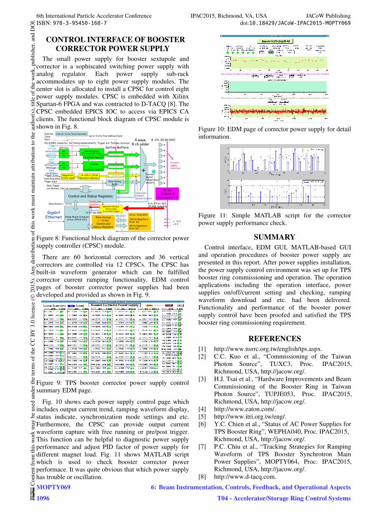
Fig. 10 shows each power supply control page which
includes output current trend, ramping waveform display,
status indicate, synchronization mode settings and etc.
Furthermore, the CPSC can provide output current
waveform capture with free running or pre/post trigger.
This function can be helpful to diagnostic power supply
performance and adjust PID factor of power supply for
different magnet load. Fig. 11 shows MATLAB script
which is used to check booster corrector power
performace. It was quite obvious that which power supply
has trouble or oscillation.
Figure 10: EDM page of corrector power supply for detail
information.
Figure 11: Simple MATLAB script for the corrector
power supply performance check.
SUMMARY
Control interface, EDM GUI, MATLAB-based GUI
and operation procedures of booster power supply are
presented in this report. After power supplies installation,
the power supply control environment was set up for TPS
booster ring commissioning and operation. The operation
applications including the operation interface, power
supplies on/off/current setting and checking, ramping
waveform download and etc. had been delivered.
Functionality and performance of the booster power
supply control have been proofed and satisfied the TPS
booster ring commissioning requirement.
REFERENCES
[1] http://www.nsrrc.org.tw/english/tps.aspx.
[2] C.C. Kuo et al., “Commissioning of the Taiwan
Photon Source”, TUXC3, Proc. IPAC2015,
Richmond, USA, http://jacow.org/.
[3] H.J. Tsai et al., “Hardware Improvements and Beam
Commissioning of the Booster Ring in Taiwan
Photon Source”, TUPJE053, Proc. IPAC2015,
Richmond, USA, http://jacow.org/.
[4] http://www.eaton.com/.
[5] http://www.itri.org.tw/eng/.
[6] Y.C. Chien et al., “Status of AC Power Supplies for
TPS Booster Ring”, WEPHA040, Proc. IPAC2015,
Richmond, USA, http://jacow.org/.
[7] P.C. Chiu et al., “Tracking Strategies for Ramping
Waveform of TPS Booster Synchrotron Main
Power Supplies”, MOPTY064, Proc. IPAC2015,
Richmond, USA, http://jacow.org/.
[8] http://www.d-tacq.com.
6th International Particle Accelerator Conference IPAC2015, Richmond, VA, USA JACoW PublishingISBN: 978-3-95450-168-7 doi:10.18429/JACoW-IPAC2015-MOPTY069
MOPTY0691096
Cont
entf
rom
this
wor
km
aybe
used
unde
rthe
term
soft
heCC
BY3.
0lic
ence
(©20
15).
Any
distr
ibut
ion
ofth
isw
ork
mus
tmai
ntai
nat
tribu
tion
toth
eau
thor
(s),
title
ofth
ew
ork,
publ
isher
,and
DO
I.
6: Beam Instrumentation, Controls, Feedback, and Operational AspectsT04 - Accelerator/Storage Ring Control Systems