Embed Size (px)
Citation preview
R. Höß (Fuel Cell Cooling System, Daimler AG) | GT-Conference | 22.10.2012
Control Engineering with a Transient Model of a Fuel Cell Coolant Loop in GT-Suite
R. Höß (Fuel Cell Cooling System, Daimler AG)
1
Control Engineering with a Transient Model of a Fuel Cell Coolant Loop in GT-Suite
Agenda
1. Context - Fuel Cell Car-Development at Daimler
2. Introduction - Cooling System for Fuel Cell Cars
3. Modelling
4. Model Verification
5. 3 Concepts of a Main Fan Controller
6. Simulation and Results
7. Conclusion and Achivements
R. Höß (Fuel Cell Cooling System, Daimler AG) | GT-Conference | 22.10.2012 2
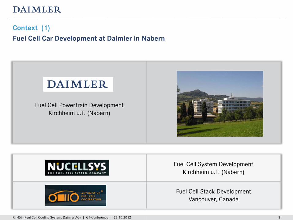
Fuel Cell System Development Kirchheim u.T. (Nabern)
Fuel Cell Stack Development Vancouver, Canada
Context (1) Fuel Cell Car Development at Daimler in Nabern
R. Höß (Fuel Cell Cooling System, Daimler AG) | GT-Conference | 22.10.2012 3
Fuel Cell Powertrain Development Kirchheim u.T. (Nabern)
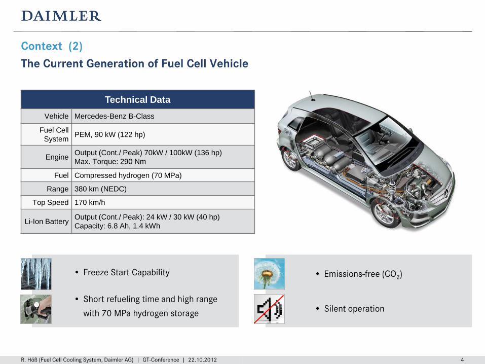
Context (2) The Current Generation of Fuel Cell Vehicle
R. Höß (Fuel Cell Cooling System, Daimler AG) | GT-Conference | 22.10.2012 4
Technical Data Vehicle Mercedes-Benz B-Class
Fuel Cell System PEM, 90 kW (122 hp)
Engine Output (Cont./ Peak) 70kW / 100kW (136 hp) Max. Torque: 290 Nm
Fuel Compressed hydrogen (70 MPa)
Range 380 km (NEDC)
Top Speed 170 km/h
Li-Ion Battery Output (Cont./ Peak): 24 kW / 30 kW (40 hp) Capacity: 6.8 Ah, 1.4 kWh
• Freeze Start Capability
• Short refueling time and high range
with 70 MPa hydrogen storage
• Emissions-free (CO2)
• Silent operation
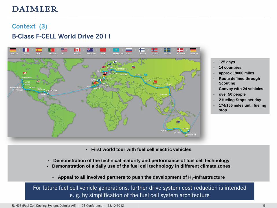
Context (3) B-Class F-CELL World Drive 2011
R. Höß (Fuel Cell Cooling System, Daimler AG) | GT-Conference | 22.10.2012 5
• 125 days • 14 countries • approx 19000 miles • Route defined through
Scouting • Convoy with 24 vehicles • over 50 people • 2 fueling Stops per day • 174/155 miles until fueling
stop
• First world tour with fuel cell electric vehicles
• Demonstration of the technical maturity and performance of fuel cell technology • Demonstration of a daily use of the fuel cell technology in different climate zones
• Appeal to all involved partners to push the development of H2-Infrastructure
For future fuel cell vehicle generations, further drive system cost reduction is intended e. g. by simplification of the fuel cell system architecture
R. Höß (Fuel Cell Cooling System, Daimler AG) | GT-Conference | 22.10.2012 6
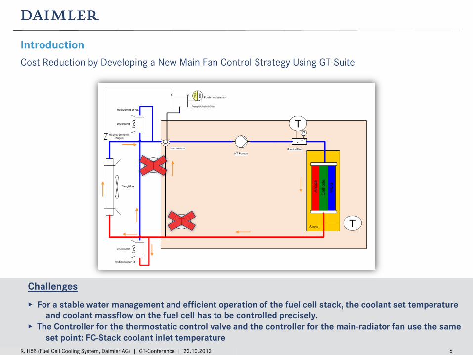
Introduction Cost Reduction by Developing a New Main Fan Control Strategy Using GT-Suite
Challenges
▸ For a stable water management and efficient operation of the fuel cell stack, the coolant set temperature and coolant massflow on the fuel cell has to be controlled precisely.
▸ The Controller for the thermostatic control valve and the controller for the main-radiator fan use the same set point: FC-Stack coolant inlet temperature
R. Höß (Fuel Cell Cooling System, Daimler AG) | GT-Conference | 22.10.2012 7
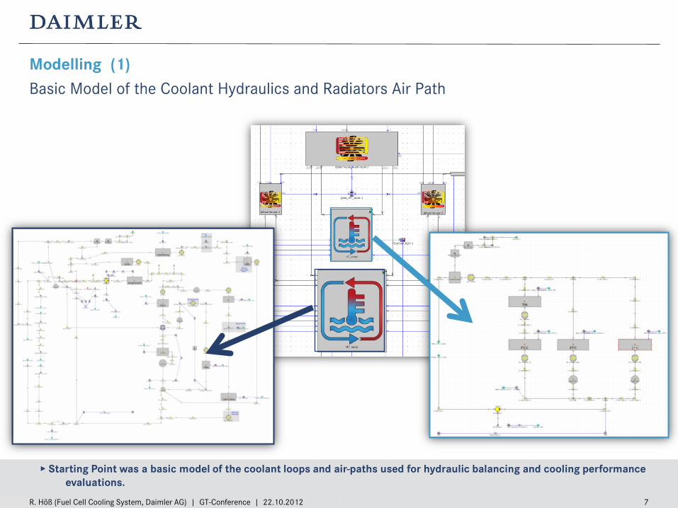
Modelling (1) Basic Model of the Coolant Hydraulics and Radiators Air Path
High Temperature Coolant Loop Low Temperature Coolant Loop ▸ Starting Point was a basic model of the coolant loops and air-paths used for hydraulic balancing and cooling performance evaluations.
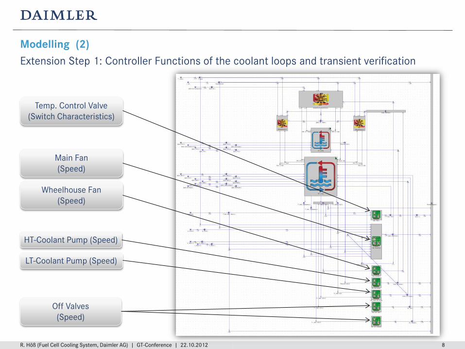
Modelling (2) Extension Step 1: Controller Functions of the coolant loops and transient verification
R. Höß (Fuel Cell Cooling System, Daimler AG) | GT-Conference | 22.10.2012 8
HT-Coolant Pump (Speed)
Temp. Control Valve (Switch Characteristics)
Off Valves (Speed)
Main Fan (Speed)
LT-Coolant Pump (Speed)
Wheelhouse Fan (Speed)
R. Höß (Fuel Cell Cooling System, Daimler AG) | GT-Conference | 22.10.2012 9
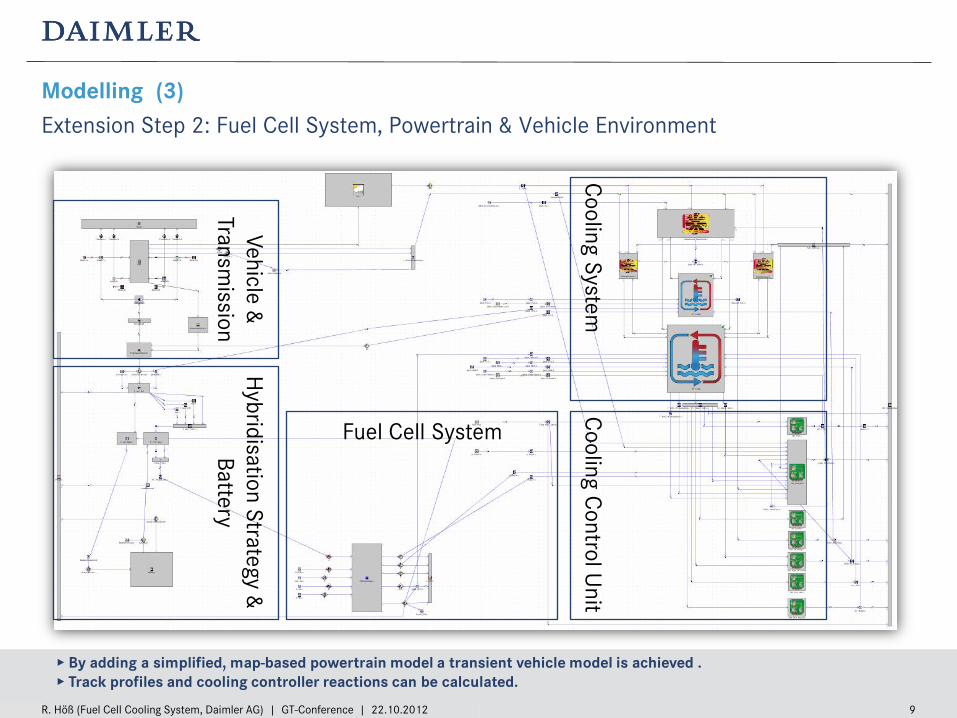
Modelling (3) Extension Step 2: Fuel Cell System, Powertrain & Vehicle Environment
▸ By adding a simplified, map-based powertrain model a transient vehicle model is achieved . ▸ Track profiles and cooling controller reactions can be calculated.
Vehicle &
Transmission
Fuel Cell System
Hybridisation Strategy &
Battery
Cooling C
ontrol Unit
Cooling System
R. Höß (Fuel Cell Cooling System, Daimler AG) | GT-Conference | 22.10.2012 10
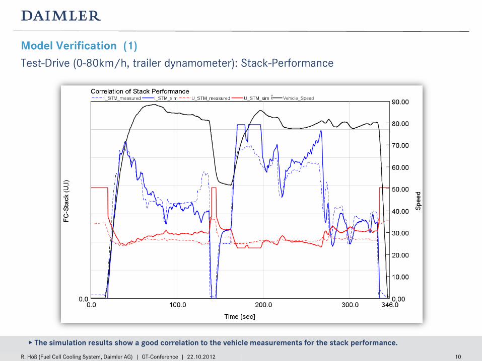
Model Verification (1) Test-Drive (0-80km/h, trailer dynamometer): Stack-Performance
▸ The simulation results show a good correlation to the vehicle measurements for the stack performance.
R. Höß (Fuel Cell Cooling System, Daimler AG) | GT-Conference | 22.10.2012 11
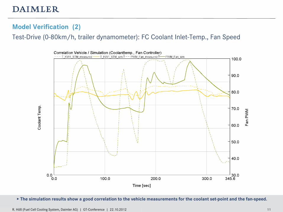
Model Verification (2) Test-Drive (0-80km/h, trailer dynamometer): FC Coolant Inlet-Temp., Fan Speed
▸ The simulation results show a good correlation to the vehicle measurements for the coolant set-point and the fan-speed.
R. Höß (Fuel Cell Cooling System, Daimler AG) | GT-Conference | 22.10.2012 12
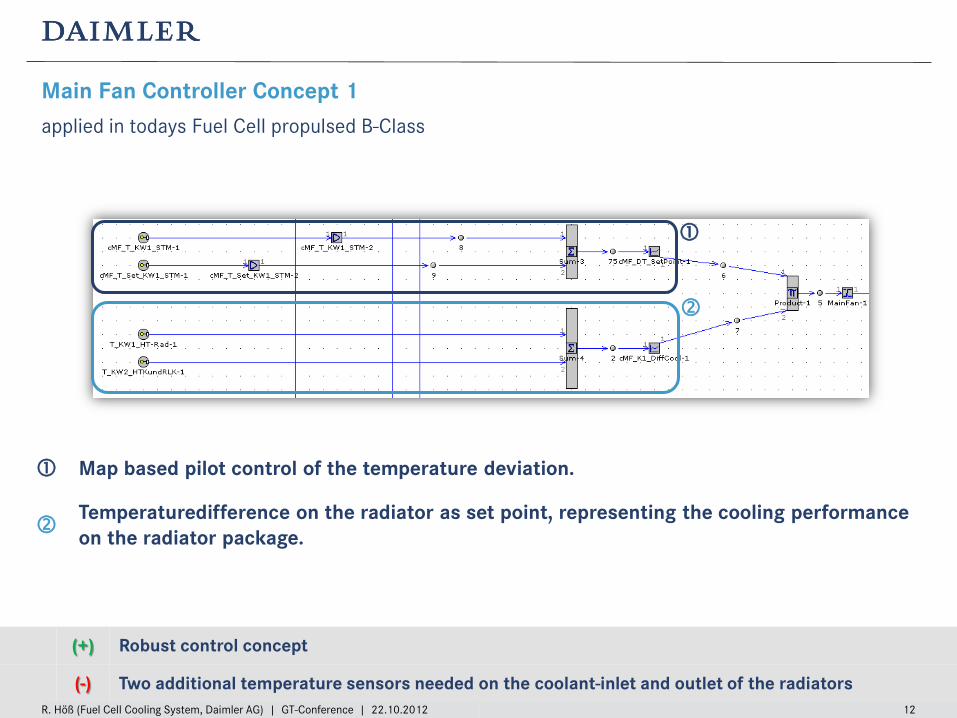
Main Fan Controller Concept 1 applied in todays Fuel Cell propulsed B-Class
(+) Robust control concept
(-) Two additional temperature sensors needed on the coolant-inlet and outlet of the radiators
Map based pilot control of the temperature deviation.
Temperaturedifference on the radiator as set point, representing the cooling performance on the radiator package.
R. Höß (Fuel Cell Cooling System, Daimler AG) | GT-Conference | 22.10.2012 13
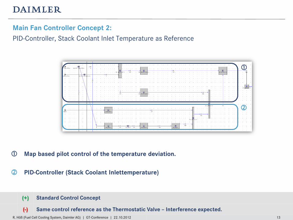
Main Fan Controller Concept 2: PID-Controller, Stack Coolant Inlet Temperature as Reference
Map based pilot control of the temperature deviation.
PID-Controller (Stack Coolant Inlettemperature)
(+) Standard Control Concept
(-) Same control reference as the Thermostatic Valve – Interference expected.
R. Höß (Fuel Cell Cooling System, Daimler AG) | GT-Conference | 22.10.2012 14
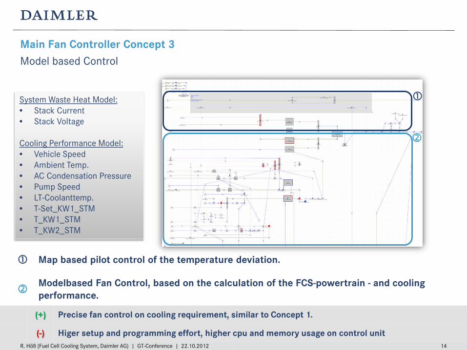
Main Fan Controller Concept 3 Model based Control
(+) Precise fan control on cooling requirement, similar to Concept 1.
(-) Higer setup and programming effort, higher cpu and memory usage on control unit
Map based pilot control of the temperature deviation.
Modelbased Fan Control, based on the calculation of the FCS-powertrain - and cooling performance.
System Waste Heat Model: • Stack Current • Stack Voltage Cooling Performance Model: • Vehicle Speed • Ambient Temp. • AC Condensation Pressure • Pump Speed • LT-Coolanttemp. • T-Set_KW1_STM • T_KW1_STM • T_KW2_STM
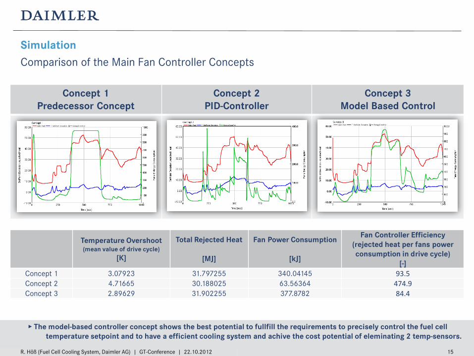
Concept 1 Predecessor Concept
Concept 2 PID-Controller
Concept 3 Model Based Control
R. Höß (Fuel Cell Cooling System, Daimler AG) | GT-Conference | 22.10.2012 15
Simulation Comparison of the Main Fan Controller Concepts
▸ The model-based controller concept shows the best potential to fullfill the requirements to precisely control the fuel cell temperature setpoint and to have a efficient cooling system and achive the cost potential of eleminating 2 temp-sensors.
Temperature Overshoot (mean value of drive cycle)
[K]
Total Rejected Heat
[MJ]
Fan Power Consumption
[kJ]
Fan Controller Efficiency (rejected heat per fans power consumption in drive cycle)
[-] Concept 1 3.07923 31.797255 340.04145 93.5 Concept 2 4.71665 30.188025 63.56364 474.9 Concept 3 2.89629 31.902255 377.8782 84.4
R. Höß (Fuel Cell Cooling System, Daimler AG) | GT-Conference | 22.10.2012 16
Conclusion and Achivements Control Engineering with GT-Suite
Modelling and Simulation
• Successful setup and simulation of a fastrunning fuel cell vehiclemodell within GT-Suite.
• Approved correlation of the simulation model even on vehicle-level with simulated drive-cycles.
• But the verified transient behavior especially of the coolant loop is essential.
Control Engineering
• Evaluation of controller concepts regarding effectivity and efficiency with this model.
• Controller response can be optimised in detail.
• Maturity of control unit software can be raised especially in early software cycles.
• Test drive efforts for software development can be reduced.
• Elemination of 2 temperature sensors seem to be achivable.

Thanks for your attention!
For further information please visit: www.daimler.com/technologie-und-innovation/antriebe/elektrische-antriebe/brennstoffzelle
R. Höß (Fuel Cell Cooling System, Daimler AG) | GT-Confefence | 22.10.2012 17