Embed Size (px)
Citation preview
CONTRACT NUMBER NAS8-37756
FINAL REPORT ONORBIT ELECTRON BEAM WELDING EXPERIMENT DEFINITION
WILLIAM H. HOOPER EXPERIMENT PROJECT MANAGER
for Industry and University In-Space Technology Experiments
Technology Theme: In-Space Operations - Maintenance and Repair
CONTRACTOR ORGANIZATION: MARTIN MARIETTA MANNED SPACE SYSTEMS DATE OF SUBMISSION: SEPTEMBER 27,1989
https://ntrs.nasa.gov/search.jsp?R=19900006115 2018-05-15T08:28:44+00:00Z
FOREWORD
This Final Report has been prepared under contract NAS8-37756 issued September 28, 1988, by the National Aeronautics and Space Administration, Office of Aeronautics and Space Technology, Washington, D.C.
The study described in the report has been prepared by Martin Marietta at the Michoud Assembly Facility, New Orleans, Louisiana, under the direction of Mr. William H. Hooper, Experiment Project Manager. An Interdivisional Operations Directive for the development of detailed functional diagrams and schedules was managed by Mr. Michael Nance, Martin Marietta Denver Aerospace Division.
TABLE OF CONTENTS
SECT1 ON
1 .o
2.0
3.0
4.0
5.0
6.0
7.0
8.0
9.0
TITLE
BACKGROUND ...........................................................................................
FLIGHT EXPERIMENT OBJECTIVES AND SCOPE ............................
JUSTIFICATION ..........................................................................................
POTENTIAL PAYOFFS AND BENEFITS ................................................
INTERRELATIONSHIPS ............................................................................
TECHNICAL DESCRIPTION OF THE FLIGHT EXPERIMENT.. ............................................................................................
ANALYTICAL AND EXPERIMENTAL RESULTS S U PPO RTI NG P RED ICTE D PERFORMANCE.. ....................................
OUTLINE FOR DEVELOPING FLIGHT HARDWARE AND SOFWARE ........................................................................................
INITIAL ASSESSMENT OF THE DEVELOPMENT COSTS AND SCHEDULES .....................................................................
iii
' , .
e
LIST OF FIGURES
FIGURES TITLE
1 ,o-1
1 .o-2
6.0-1
6.0-2
6.0-3
6.0-4
6.0-5
6.0-6
6.0-7
6.0-8
7.2-1
7.2-2
7.2-3
7.2-4
7.2-5
7.2-6
7.2-7
7.2-8
7.2-9
Soviet Hand-Held, Onorbit EB Welding System
Typical Simulated Spacecraft Penetration
Basic Design of Test Panel for Proposed Onorbit We Id i ng Ex pe ri me n t
Test Panel of Preferred Double Concentric Ring Design
Test Panel with Build-In Graduated Weld Gaps
Test Panel for Leakage and Burst Testing
Test Panel Simulating Penetration at a Stiffener Rib
Schematic Drawing of Experiment Configuration
Portable EB Weld Gun
Pow e r/Co n t ro Is Package
Weld Bead Profile with 0" Beam Deflection, 2KW Power
Weld Bead Produced at 18" Deflection, 2KW
Weld Bead Produced at 18" Deflection 1.7KW
Weld Bead Produced at 18" Deflection 1.5KW
Top Bead of Circular Weld
Single 4 inch Diameter Circular Weld
Double Annular Weld of Preferred Configuration
Weld Width vs EB Power
Energy input of a 4 Inch Diameter Circular Weld
iv
LIST OF FIGURES
FIGURES TITLE
9.0-1
9.0-2
9.0-3 Experiment Flow
9.0-4 Simplified Experiment Functions
9.0-5 Onorbit Welding Procedure
Program Functional Diagram - MPESS Integration
Program Functional Diagram - MSUUSMP Integration
V
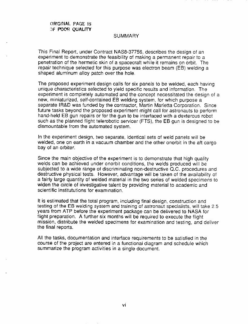
This Final Report, under Contract NAS8-37756, describes the design of an experiment to demonstrate the feasibility of making a permanent repair to a penetration of the hermetic skin of a spacecraft while it remains on orbit. The repair technique selected for this purpose was electron beam (EB) welding a shaped aluminum alloy patch over the hole.
The proposed experiment design calls for six panels to be welded, each having unique characteristics selected to yield specific results and information. The experiment is completely automated and the concept necessitated the design of a new, miniaturized, self-contained EB welding system, for which purpose a separate IR&D was funded by the contractor, Martin Marietta Corporation. Since future tasks beyond the proposed experiment might call for astronauts to perform hand-held EB gun repairs or for the gun to be interfaced with a dexterous robot such as the planned flight telerobotic servicer (FTS), the EB gun is designed to be dismountable from the automated system.
In the experiment design, two separate, identical sets of weld panels will be welded, one on earth in a vacuum chamber and the other onorbit in the aft cargo bay of an orbiter.
Since the main objective of the experiment is to demonstrate that high quality welds can be achieved under onorbit conditions, the welds produced will be subjected to a wide range of discriminating non-destructive Q.C. procedures and destructive physical tests. However, advantage will be taken of the availability of a fairly large quantity of welded material in the two series of welded specimens to widen the circle of investigative talent by providing material to academic and scientific i nstitututio ns for examination.
It is estimated that the total program, including final design, construction and testing of the EB welding system and training of astronaut specialists, will take 2.5 years from ATP before the experiment package can be delivered to NASA for flight preparation. A further six months will be required to execute the flight mission, distribute the welded specimens for examination and testing, and deliver the final reports.
All the tasks, documentation and interface requirements to be satisfied in the course of the project are entered in a functional diagram and schedule which summarize the program activities in a single document.
vi
1 .o BAC KG ROUND
An aluminum alloy, manned space vehicle circling the earth for 25 years is statistically at risk to penetration damage by micro- meteoroids, and there is currently a great deal of interest in the feasibility of carrying out permanent repairs to such damage while the spacecraft remains on orbit.
The need for procedures to make permanent repairs quickly and effectively is based on both humane and economic grounds. First, there is the mounting risk to the safety of astronaut crews forced to await the arrival of a rescue ship and, secondly, the cost of returning the damaged structure to earth for repair would be enormous. The payback on even the most sophisticated repair system salvaging a space vehicle on-site would be many, many times the cost of the equipment.
Since the early 19603, when manned space flight became a reality, much thought has been given to the kind of tools astronauts would need to assemble large space structures in space and to maintain them over long periods of time. Because space vehicles are built almost entirely of metallic materials and welding is the primary assembly process used in their construction, welding has naturally emerged as the leading technology to be mastered and applied in the space environment.
Even from the earliest days when it was a little-known, highly specialized procedure, electron beam (EB) welding had been singled out from other available electric arc and power beam processes for special attention by aerospace engineers in contact with the problems of in-space repair and maintenance. By 1963, in fact, parallel programs led by NASA and its contractors in the United States, and in the USSR by the Paton Electric Welding Institute of Kiev in the Ukraine were already developing the first design of miniaturized,
1 .o
lightweight EB welding systems capable of melting through stainless steel sheet 0.075 inches thick at 15 inches per minute.
In the U.S. development program, Westinghouse Electric Corporation (1 ) designed the first EB welding apparatus, described in the March 1968 issue of Westinghouse Engineer. A flight experiment designated the M493 Electron Beam Weld Experiment was formally approved by the Manned Flight Experiments Board in 1966. However, because of burgeoning interest in the possibility of manufacturing metallic materials in space to serve special applications on earth, the welding experiment was redesigned as M551 Metals Melting.
The M551 experiment (2)was performed on Skylab I in the M512 Materials Processing Facility in June 1973. Melting experiments producing bead-on-plate weld deposits were completed on specimens of type 304 stainless steel, 2219-T87 aluminum alloy, and pure tantalum using the weld parameters: 80MA current, 20KV accelerating voltage and 35 ipm travel speed.
A highly ingenious hand-held EB welding gun was designed and built by Hamilton Standard in the mid 1960's and described in a paper presented(3) at the Fourth Space Congress in 1967. This gun was operated in a man-rated vacuum chamber on the ground and produced satisfactory bead-on-plate welds in 304 stainless steel, 2219 aluminum alloy and titanium at a power level of 1.5KW. This
demonstration used a conventional power supply, since development of a compact unit capable of operating in a vacuum was not part of the contract under which the E6 gun was developed. It is believed that an example of this EB gun design may be in storage in the archives of the NASA Space Museum at Huntsville, Alabama.
In the meantime, the Soviets had been carrying out experiments aimed at developing onorbit repair and construction techniques and, in addition to EB welding, had experimented with consumable
1.1
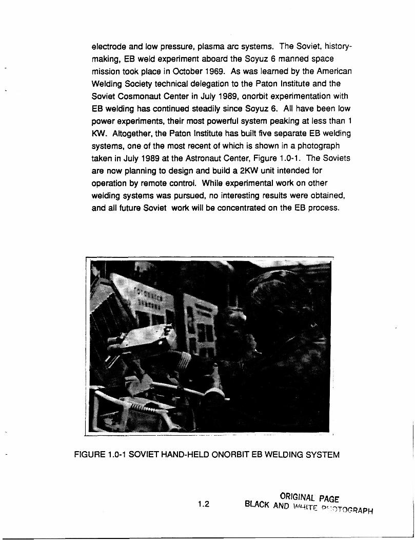
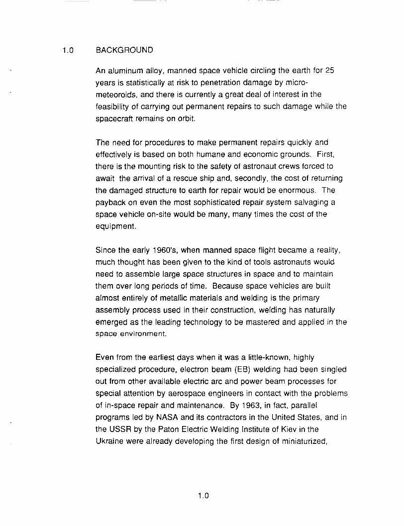
electrode and low pressure, plasma arc systems. The Soviet, history- making, EB weld experiment aboard the Soyuz 6 manned space mission took place in October 1969. As was learned by the American Welding Society technical delegation to the Paton Institute and the Soviet Cosmonaut Center in July 1989, onorbit experimentation with EB welding has continued steadily since Soyuz 6. All have been low power experiments, their most powerful system peaking at less than 1 KW. Altogether, the Paton Institute has built five separate E9 welding systems, one of the most recent of which is shown in a photograph taken in July 1989 at the Astronaut Center, Figure 1 .O-1. The Soviets are now planning to design and build a 2KW unit intended for operation by remote control. While experimental work on other welding systems was pursued, no interesting results were obtained, and all future Soviet work will be concentrated on the EB process.
J _- -
FIGURE 1 .O-1 SOVIET HAND-HELD ONORBIT EB WELDING SYSTEM
1.2
ORIGINAL PAGE BLACK AND WHITE PHOTOGRAPH
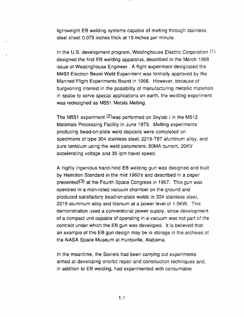
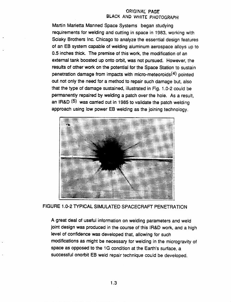
Martin Marietta Manned Space Systems began studying requirements for welding and cutting in space in 1983, working with Sciaky Brothers Inc. Chicago to analyze the essential design features of an EB system capable of welding aluminum aerospace alloys up to 0.5 inches thick. The premise of this work, the modification of an external tank boosted up onto orbit, was not pursued. However, the results of other work on the potential for the Space Station to sustain penetration damage from impacts with micro-meteoroids(4) pointed out not only the need for a method to repair such damage but, also that the type of damage sustained, illustrated in Fig. 1 .O-2 could be permanently repaired by welding a patch over the hole. As a result, an IR&D (5) was carried out in 1985 to validate the patch welding approach using low power EB welding as the joining technology.
FIGURE 1 .O-2 TYPICAL SIMULATED SPACECRAFT PENETRATION
A great deal of useful information on welding parameters and weld joint design was produced in the course of this IR&D work, and a high level of confidence was developed that, allowing for such modifications as might be necessary for welding in the microgravity of space as opposed to the 1G condition at the Earth's surface, a successful onorbit EB weld repair technique could be developed.
1.3
Martin Marietta Manned Space Systems was, therefore, well-primed to submit a proposal for an onorbit EB welding flight experiment when, in 1987, NASA solicited proposals for the Industry and University In-Space Technology Experiments Program. Our selection by NASA to produce, under contract number NAS8-37756, a detailed description of the experiment outlined in our proposal represented another step forward in our objective to develop and demonstrate EB welding as a safe and effective onorbit repair tool.
Parallel to but separate from our work on experiment design, we have developed with the aid of two subcontractors two different approaches to the design of miniaturized, lightweight EB welding systems for onorbit weld repair demonstrations. In the event that this Final Report, which is the deliverable item under the Phase A contract, leads to a Phase B contract, it would be our intention to proceed with the construction and ground testing of one of these new EB welding systems.
1.4
2.0 FLIGHT EXPERIMENT OBJECTIVES AND SCOPE
The objective of the onorbit welding experiment is to demonstrate that the EB welding process can be safely operated and controlled to produce high integrity welds in the space environment.
The special objective is to apply the EB welding process effectively and safely in the specific case of simulating a permanent repair to a hull penetration in Space Station made by the impact of a micro- meteoroid.
The scope of the experiment encompasses welding a series of specially designed weld panels under fully automated control in a self contained chamber which will be installed in the MPESS section of the payload area of the orbiter. Two aerospace alloys will be represented: 221 9-T87 as the baseline material of construction for Space Station, and Martin Marietta's experimental aluminum-lithium alloy Weldalite (TM) 049. An identical series of weld panels will be EB welded in a vacuum chamber on the ground using the same EB gun, power system, and welding parameters, and the physical and metallurgical characteristics of the two series will be extensively evaluated and compared. Testing procedures that will be used will include, but not be limited to, dye penetrant and x-ray examination of welds, hardness tests, tensile testing, pressurization/leak testing, burst strength, optical and electron microscope metallography, and micro-chemical analysis of micro-structural features of materials welded on earth and onorbit.
2.0
3.0 J U STI Fl CAT1 ON
Justification for the proposed flight experiment is four-fold;
The combined environmental effects of micro-gravity, the space vacuum, and space environment temperatures cannot be simulated on earth to enable the E6 welding technique to be evaluated qualitatively and quantatively as a method for onorbit repair.
Successful demonstration of the onorbit E6 Welding Experiment will provide the basis for developing the lightweight, space hardened equipment essential for onorbit spacecraft repair, maintenance and operations.
Availability of the basic E6 welding system and software will provide a versatile tool capable of being modified to carry out a variety of assembly operations in space either in an automated format or interfaced with the Flight Telerobotic Servicer now under development by Martin Marietta.
The American Welding Society Technical Delegation to the Soviet Union in July 1989 ascertained that the Soviets have extensively investigated arc welding and power beam welding processes, and concluded on the basis of experimental data that only the E 6 welding process has any real potential for development as an onorbit tool. The Soviets, however, have not carried out any automated experiments or used beam powers as high as the 2KW/2OKV level we propose in our experiment. Successful completion of our experiment would, therefore, carry significant international prestige.
3.0
4.0 POTENTIAL PAYOFFS AND BENEFITS
4.1 Payoffs
In the event of a crippling penetration of the hull of a Space Station module, the cost of providing EBW equipment for performing permanent weld repairs onorbit will be insignificant compared to the cost of bringing the module back to earth for repair and then returning it to orbit again.
Capability to make repairs to manned vehicles within the allowable time frame to preserve the safety of the astronaut crew has an inestimably high payoff.
4.2 Benefits
Successful completion of the proposed experiment will:
Verify the effectiveness of the EB welding process in performing simulated repairs to damaged spacecraft in the space environment.
Validate the quality and metallurgical characteristics of onorbit EB welds.
Confirm that automation of the welding process eliminates the need for manual welding skills on the part of the astronaut specialist operating the equipment.
Make available to the NASA space program a proven, versatile, welding tool capable, with relatively slight modification, of performing a range of welding, heating, cutting and brazing operations in the high vacuum, microgravity environment of space.
4.0
Produce, in the same development time frame as is planned for the NASA/Martin Marietta Flight Telerobotic Servicer (FTS) system, a versatile tool capable of being operated remotely at a higher power and flexibility than could be countenanced in the hand-held mode.
4.1
5.0 INTERRELATIONSHIPS
From the initial announcement of the "Outreach" program to select flight experiments for the STS in the 1990's period, a significant emphasis has been placed on the need for a space hardened welding process which could perform a variety of repair, maintenance and assembly tasks onorbit.
Martin Marietta's election to demonstrate the effectiveness of the EB welding approach for this purpose has led a number of industrial corporations, academic institutions and government agencies to express interest in the proposed experiment and, in particular, to inquire about the EB welding system basic design and the degree of flexibility to perform other welding tasks that might be built into the system.
McDonnell Douglas and Rockwell International, among the aerospace companies involved in the STS and Space Station programs, have notified us of their interest in onorbit, EB welding technology. These two companies, like Martin Marietta, contributed a technical manager to the five man American Welding Society delegation to the USSR in July 1989 for joint discussions on welding in space, from which the EB welding approach emerged a clear winner over competing technologies. As has been well publicized, the Soviets have completed many EB welding experiments in the course of their manned space flight program.
Others in industry important to the success of the proposed experiment are the EB welding equipment builders. Both Ferranti- Sciaky and Wentgate-EBTEC have been subcontracted by Martin Marietta to produce detailed conceptual designs for systems to meet the functional criteria and size-weight considerations of the proposed experiment .
5.0
In the academic arena, Ohio State University, Department of Welding Engineering, has been actively supportive of our proposal to develop EB onorbit welding technology. The Chairman of the department, Professor David Dickenson acted as leader of the AWS delegation to Russia in July, and concurred in the selection of EB welding for near term, welding in space development. Both Ohio State University and Colorado School of Mines have expressed interest in collaborating in the characterization of metallurgical features of the welded materials. In a more general way, the Welding Institute of Great Britain, and Edison Welding Institute of Columbus, Ohio, have contacted Martin Marietta to express their interest in the proposed experiment and offer assistance in evaluating results.
Our interrelationships with NASA are more extensive than any of the foregoing. Helpful advice and counsel have been solicited from and freely given by experts at NASA headquarters and Marshall Space Flight Center in the technological areas of microgravity, vacuum pressure and temperature variations in the orbiter cargo bay and the radiation resistance of astronaut space suits. An especially cordial relationship has existed throughout the twelve month study with Dr. A Nunes, MSFC, project technical monitor. Much of our appreciation of what is feasible in EVA tasks to be performed by astronaut specialists has been derived from conversations with and presentations by Dr. Bonnie Dunbar of the J.S.C. Astronaut Office, Flight Crew Operations Directorate.
Both as a courtesy and as a matter of national importance, copies of protocols written by two of the Soviet agencies hosting the July visit by the US American Welding Society delegation to the USSR were sent to the President, the Right Honorable George Bush and the State Department. These protocols contained offers of collaboration from the USSR in important space programs, including the use of Russian EB welding equipment aboard a future US space shuttle mission.
5.1
6.0 TECHNICAL DESCRIPTION OF THE FLIGHT EXPERIMENT
The experiment described below has been designed to be carried out in fully automated mode in a self-contained enclosure. This decision has been made because, at the time of writing this final report, there were no assurances that an astronaut operating the equipment in hand-held mode could be adequately shielded from x-ray radiation emanating from the weldment. However, it should be noted that the EB gun has been designed for both automated and hand-held operation, and it is confidently anticipated that astronaut shielding problems will be resolved and so permit the execution of hand held or astronaut-cont rolled, telero botic E B welding experiments on future missions.
Basically, the experiment simulates the repair of a spacecraft hull penetration by welding a shaped patch over the hole, the patch becoming a permanent addition to the structure. The weld format to be used is a lap weld, while the weld panel consists of two circular discs, the thickness of each disc being arbitrarily defined as 0.125 in.
Weld parameters will be selected which permit the power beam to melt through the top (patch) disc and penetrate at least halfway through the bottom (hull) plate while traveling at a welding speed of 60 in. per minute. The beam will trace a circular path approximately four inches in diameter. The resultant welded specimen is shown schematically in Figure 6.0-1.
A total of six specially designed panels will be welded, as illustrated in Figures 6.0- 1 to 5, each serving a different purpose and generating specific information on the flexibility and scope of the repair welding process and the quality and metallurgical characteristics of the weld joint.
6.0
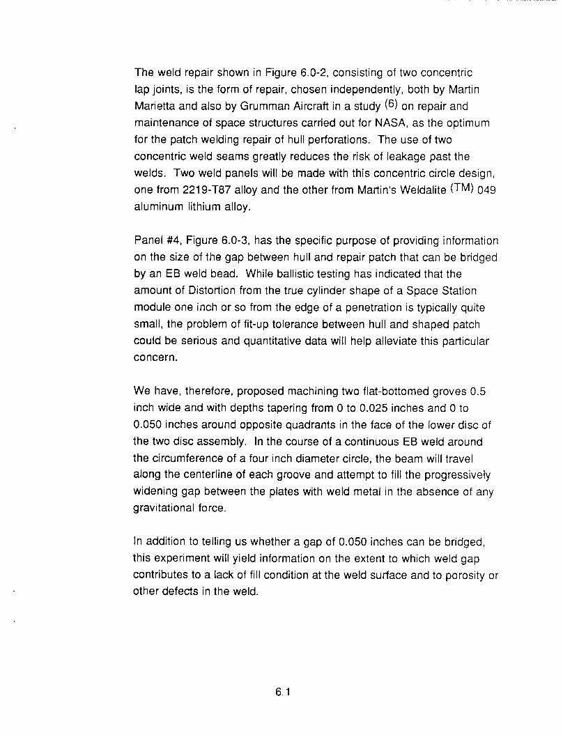
The weld repair shown in Figure 6.0-2, consisting of two concentric lap joints, is the form of repair, chosen independently, both by Martin Marietta and also by Grumman Aircraft in a study (6) on repair and maintenance of space structures carried out for NASA, as the optimum for the patch welding repair of hull perforations. The use of two concentric weld seams greatly reduces the risk of leakage past the welds. Two weld panels will be made with this concentric circle design, one from 221 9-TB7 alloy and the other from Martin's Weldalite (TM) 049 aluminum lithium alloy.
Panel #4, Figure 6.0-3, has the specific purpose of providing information on the size of the gap between hull and repair patch that can be bridged by an EB weld bead. While ballistic testing has indicated that the amount of Distortion from the true cylinder shape of a Space Station module one inch or so from the edge of a penetration is typically quite small, the problem of fit-up tolerance between hull and shaped patch could be serious and quantitative data will help alleviate this particular concern.
We have, therefore, proposed machining two flat-bottomed groves 0.5 inch wide and with depths tapering from 0 to 0.025 inches and 0 to 0.050 inches around opposite quadrants in the face of the lower disc of the two disc assembly. In the course of a continuous EB weld around the circumference of a four inch diameter circle, the beam will travel along the centerline of each groove and attempt to fill the progressively widening gap between the plates with weld metal in the absence of any g ravi t at i o n a1 f o rce .
In addition to telling us whether a gap of 0.050 inches can be bridged, this experiment will yield information on the extent to which weld gap contributes to a lack of fill condition at the weld surface and to porosity or other defects in the weld.
6.1
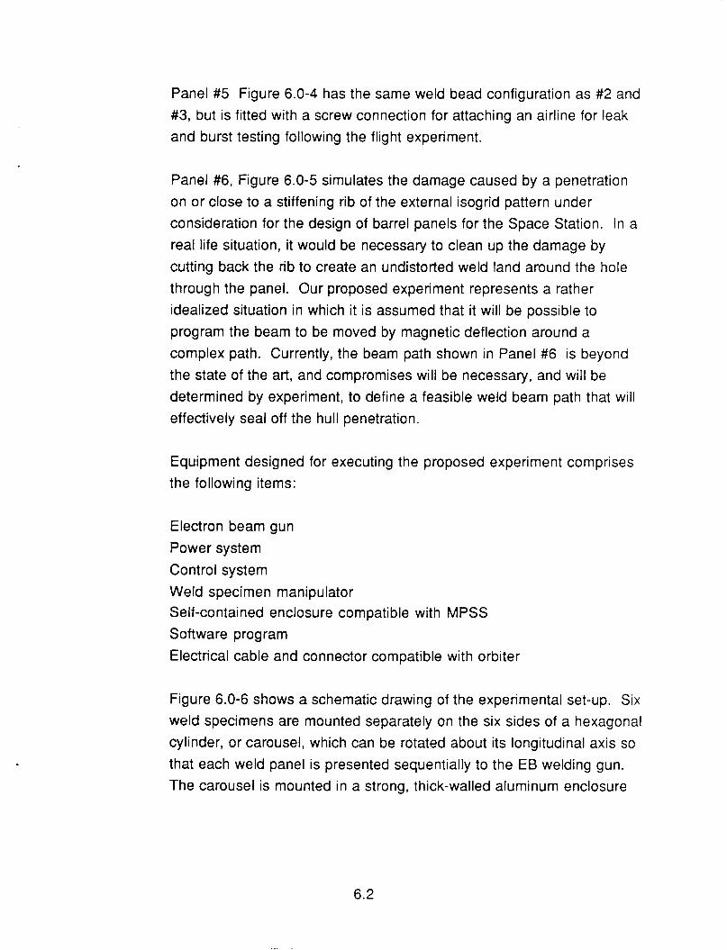
Panel #5 Figure 6.0-4 has the same weld bead configuration as #2 and #3, but is fitted with a screw connection for attaching an airline for leak and burst testing following the flight experiment.
Panel #6, Figure 6.0-5 simulates the damage caused by a penetration on or close to a stiffening rib of the external isogrid pattern under consideration for the design of barrel panels for the Space Station. In a real life situation, it would be necessary to clean up the damage by cutting back the rib to create an undistorted weld land around the hole through the panel. Our proposed experiment represents a rather idealized situation in which it is assumed that it will be possible to program the beam to be moved by magnetic deflection around a complex path. Currently, the beam path shown in Panel #6 is beyond the state of the art, and compromises will be necessary, and will be determined by experiment, to define a feasible weld beam path that will effectively seal off the hull penetration.
Equipment designed for executing the proposed experiment comprises the following items:
Electron beam gun Power system Control system Weld specimen manipulator Self-contained enclosure compatible with MPSS Software program Electrical cable and connector compatible with orbiter
Figure 6.0-6 shows a schematic drawing of the experimental set-up. Six weld specimens are mounted separately on the six sides of a hexagonal cylinder, or carousel, which can be rotated about its longitudinal axis so that each weld panel is presented sequentially to the EB welding gun. The carousel is mounted in a strong, thick-walled aluminum enclosure
6.2
compatible with the standard fastener points of the payload bay of the orbiter in the MPESS/MSL configuration.
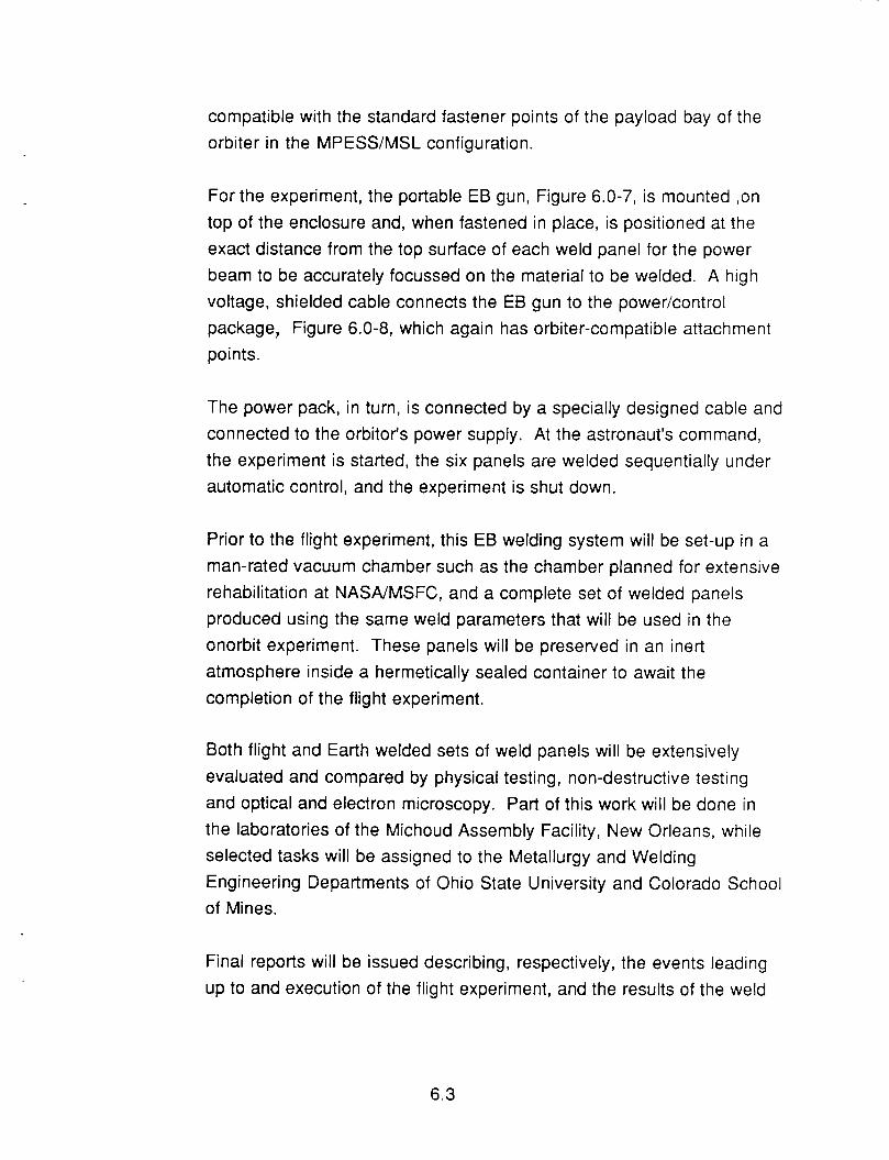
For the experiment, the portable EB gun, Figure 6.0-7, is mounted ,on top of the enclosure and, when fastened in place, is positioned at the exact distance from the top surface of each weld panel for the power beam to be accurately focussed on the material to be welded. A high voltage, shielded cable connects the EB gun to the power/control package, Figure 6.0-8, which again has orbiter-compatible attachment points.
The power pack, in turn, is connected by a specially designed cable and connected to the orbitor's power supply. At the astronaut's command, the experiment is started, the six panels are welded sequentially under automatic control, and the experiment is shut down.
Prior to the flight experiment, this EB welding system will be set-up in a man-rated vacuum chamber such as the chamber planned for extensive rehabilitation at NASNMSFC, and a complete set of welded panels produced using the same weld parameters that will be used in the onorbit experiment. These panels will be preserved in an inert atmosphere inside a hermetically sealed container to await the completion of the flight experiment.
Both flight and Earth welded sets of weld panels will be extensively evaluated and compared by physical testing, non-destructive testing and optical and electron microscopy. Part of this work will be done in the laboratories of the Michoud Assembly Facility, New Orleans, while selected tasks will be assigned to the Metallurgy and Welding Engineering Departments of Ohio State University and Colorado School of Mines.
Final reports will be issued describing, respectively, the events leading up to and execution of the flight experiment, and the results of the weld
6.3
panel characterization studies. In addition, recommendations will be made regarding future hand-held and FTS-assisted, onorbit welding demonstrations, together with proposals for any modification and improvement to the welding system hardware and software that would increase the scope and flexibility of the equipment.
6.4
n u cn 0 n 0 K n K 0 > LL U
I c a n P
F: I! U v) U a 5 m
W m n A
6.5
n a m W
n
0 z 0 0
r a i=
z W z n U
Y (d 0
W [r
6.6
v)
- - a cn '5 I - a -
d
I- v) W I- + 9 (D
W K
> K
c a
a c c W K - a 5 Z F u a I
6.7
n a W U I I- cn (3 a
a m n
W
W
c3 z cn W I- I- cn U 3
F=
rn n a z W c3 a Y
W -I
U 0 L A W z a n I- cn W I-
a
p: 0
W U 3 c3 L
(d
I
6.8
a I- a
w m \
U W z E f i= tn
a I- > w U w I- n w z a
6.9
6.10
IJ
> U L"
3 LLJ > I- LL w -J
M
6.1 1
n a z cn z 0 I-
U 3 c3 LA z 0 0 A W z 4
- a
-
a n A
2 x 0
n a 0 A W > W
W U 4
v) W A 3
W r 0 v)
A W
W
n
n
n
3
z 3 c7 n J W 3 m w
z 0 W P A
-
2 v) A W z a n
G X
8 I- W v)
W z 0
I- z k! - a n W
X W
P W v) a m d z 3 0 U c3
0 LL /
K 0 LA
W I- z 3 0 z E
n
I- W v)
A
W n
a - z
I- z : - U W P X W
k m U 0 z 0
.. W 0 a n v)
0 I-
n W I- U 0 P
v)
W U 3 v) 0 A 0 z W
-
k m U 0 z 0
0
n
a a
E
n
W I-
W
W U
v)
4 s U 0 W A 0 > 0
W I-
0 I- 3
W I I-
n
s a
I- z W 2 U W a X W
c3 z A
-
- n s n
d
A W X
z 4 I 4
z 0 I- P 0 W I I-
a -
P W I- W A : 0 0
v) -
d
a
n a n
z 3 0 c3
z
W P 4 s k m U 0 Z 0 LA 0 v) W F U W n 0 U P
n W U 4
0 0 W
: a a v) 4 W z P
W P A
a n
s A W > W A
m z 0 0 L
L n n
U u
6.1 2
7.0
7.1
ANALYTICAL AND EXPERIMENTAL RESULTS SUPPORTING PREDICTED PERFORMANCE
Our selection of performance criteria for the proposed experiment is based on solid programmatic work in the technical field of EB welding as an onorbit tool dating back to 1983. At that time we explored with Sciaky Brothers, Inc. the features that would be necessary to weld 0.5 inch thick aluminum alloy plate in space. Several related IR&D programs were carried out in subsequent years.
Analytical Results
As far as the nature of the type of damage to spacecraft we are addressing is concerned, theoretical analysis has established the high probability that Space Station will be impacted by micrometeroids or space debris in the course of a 25 year service life and that hull penetration is a likely result. Actual ballistic experiments carried out by Martin Marietta at MSFC have demonstrated that a worst case impact creates a jagged hole in the hermetic skin, bending fracture petals inwards into the interior of the module. Characteristically the contour of the metal skin a few inches out from the center of impact is almost undisturbed. This model of typical impact damage led to the conclusion that penetration damage could be satisfactorily repaired by welding a shaped patch over the hole from outside the vehicle, in the vacuum of
space. This judgement is supported by analytical studies reported in a review of structural repair procedures needed for Space Station operations which were summarized in an article (6) by Harry S. Haber of Grumman Corporation and Alberta Quina of NASA Marshall Space Flight Center published in Aerospace Engineering. The authors concurred with the widely held view that repair of spacecraft penetrations by patch welding was the best onorbit procedure and that EB welding was the best welding approach to develop for the purpose.
7.0
Analysis of environmental data pertaining to pressure, microgrativy and temperature conditions in the cargo bay during steady state conditions attained after outgassing of the orbiter structure and experimental packages has indicated a vacuum pressure of 10 -4 Torr and a temperature range of -50" to + 50°C.
A pressure of 10 -4 Torr is considered a hard vacuum most propitious for efficient EB welding operations, and is typical of many industrial EB welding operations carried out on Earth in vacuum chambers. While it is not known exactly what effect the microgravity of space will have on the Et3 welding process, the fact that the ambient pressure is so low will greatly simplify the design of the onorbit E6 welding system.
Review of the effect of variation in temperature within the range -50" to +50°C has raised no significant concerns since the heating capacity of a 2KW electron beam is so high that a 100°C difference in starting temperature of the workpiece immediately prior to welding is unlikely to affect weld performance significantly. In any event, the experiment can be performed exclusively with the cargo bay in sunlight to eliminate working in the cold cycle of each orbit, and temperature inside the enclosure will be monitored as an input into experimental results. Should it be considered necessary, space heater elements will be installed in the experiment enclosure.
Calculations have been made of the power requirements of a specially designed, EB welding system for lap welding a 0.125 inch thick aluminum alloy patch onto a 0.125 inch thick base with 50% penetration into the base material. Minimum weld beam travel speed was arbitrarily specified as 30 inches per minute but would be determined by experiment. These calculations involved several trade studies, described below.
7.1
A trade study has been made of the options of moving the electron beam either mechanically, or electrically, using magnetic deflection coils in the EB gun. For reasons of control simplicity and weight reduction, the magnetic beam deflection procedure has been selected. Another trade study was made of beam length, or distance of the EB gun from the work piece, versus the accelerating voltage (KV) of the system. Since the election had been made to keep the EB gun stationary and move the beam in the desired circular path by controlling the magnetic field around the beam, it follows that the power beam will not strike the weld panel in a direction normal to the surface but at some angle depending on the diameter of the weld path and the gun-to workpiece distance. This reduces the efficiency of energy transfer from the electron beam to the weldment to an extent which would need to be determined by experiment.
The major factor affecting the decision on beam length was the need to limit accelerating voltage. The higher the accelerating voltage the system is designed for, the greater the gun distance can be without any significant deterioration of the beam in a hard vacuum through glow discharge. On the other hand, generation of x-ray radiation increases with accelerating voltage. With these considerations in mind, it was decided to limit accelerating voltage to 20KV, which more or less mandated a gun-to-work distance of six inches and a maximum weld path diameter of four inches.
With an EB gun distance of only six inches, the enclosure holding the experiment can be made quite short. In addition to the benefit of saving weight, a short enclosure opens up the possibility of stacking the container and powerkontrols cabinet in one package, which would simplify integration with the orbiter for the flight mission. However, while this would be a small advantage for the proposed automated
7.2
7.2
experiment, it would impose a distinct limitation on any future, hand- held or remote controlled experiment that can be envisaged. It would, for example, offer very interesting task performance capability i f the onorbit EB weld system were to be integrated with the Flight Telerobotic Servicer (FTS) system currently under development for NASA by Martin Marietta Aerospace. It was decided to design the powerpack and controls as a separate unit from the experiment container.
Experimental Results
Since analysis of the likely environment conditions and safety concerns had to a large extent mandated the parameter levels at which the proposed flight experiment will be performed, relatively few experiments were required to validate the operating criteria that emerged. The target welding parameters were:
Beam power 2KW Accelerating voltage 20 KV Welding speed Beam deflection angle 18" Lap weld diameter 4 in Gun distance (focus) 6 in Vacuum pressure
30 - 60 ipm
1 0 -4 Torr
Experiments were designed to simulate a 4 inch circular weld with 0.125 in thick 221 9-T87 aluminum alloy plates. Preliminary tests showed that parameter settings of 2 KW, 20KW, 60ipm and 0" beam deflection were capable of producing a weld 50% through the bottom mating plate. Deflection of the beam, however, would adversely affect weld efficiency by an unknown amount, and it would be necessary to vary weld beam travel speed to compensate.
Initial experiments were performed by making straight path lap welds in mated 0.125 inch thick plates, varying travel speed to achieve the
7.3
required penetration. Surface oxide on the plates was removed by light scraping. The requisite beam deflection of 18" was simulated by tilting the gun by this amount from the vertical axis and welding in the downhand position.
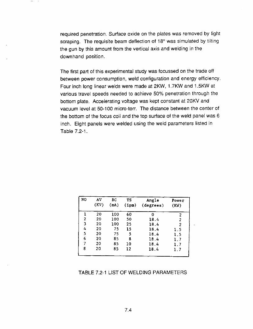
The first part of this experimental study was focussed on the trade off between power consumption, weld configuration and energy efficiency. Four inch long linear welds were made at 2KW, 1.7KW and 1.5KW at various travel speeds needed to achieve 50% penetration through the bottom plate. Accelerating voltage was kept constant at 20KV and vacuum level at 50-100 micro-torr. The distance between the center of the bottom of the focus coil and the top surface of the weld panel was 6 inch. Eight panels were welded using the weld parameters listed in Table 7.2-1.
NO AV BC TS Angle Power (W (mA) ( i p d (degrees) (KW)
1 20 100 60 0 2 2 20 100 50 18.4 2 3 20 100 25 18.4 2 4 20 75 15 18.4 1.5 5 20 75 5 18.4 1.5 6 20 85 8 18 " 4 1.7 7 20 85 10 18.4 1.7 8 20 85 12 18.4 1.7
TABLE 7.2-1 LIST OF WELDING PARAMETERS
7.4
In the second part of this experimental study, production of circular welds in the mated plates was simulated.
Two test panels were welded, the first with a single circular weld 4
inches diameter, and the other with two concentric welds 3 inch and 4
inch diameter. In both cases, the EB gun was tilted 1 8 O , which represented the deflection angle for a 4 inch diameter weld.
Macrographs were prepared of cross-sections of the weld beads of all weld panels and, in addition, photographs were taken of the weld beads produced in the circular welding experiments.
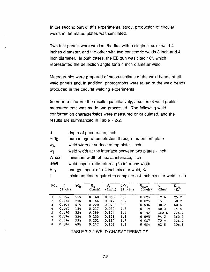
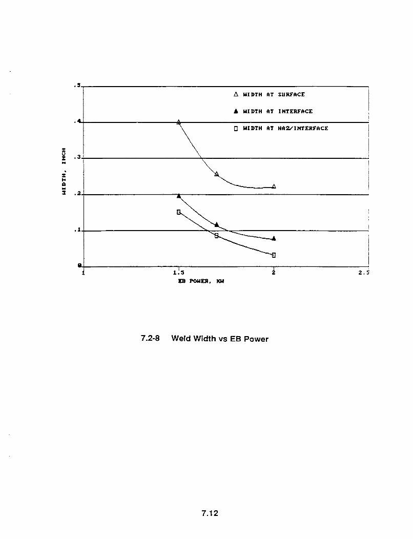
In order to interpret the results quantitatively, a series of weld profile measurements was made and processed. The following weld conformation characteristics were measured or calculated, and the results are summarized in Table 7.2-2.
d %db
WS
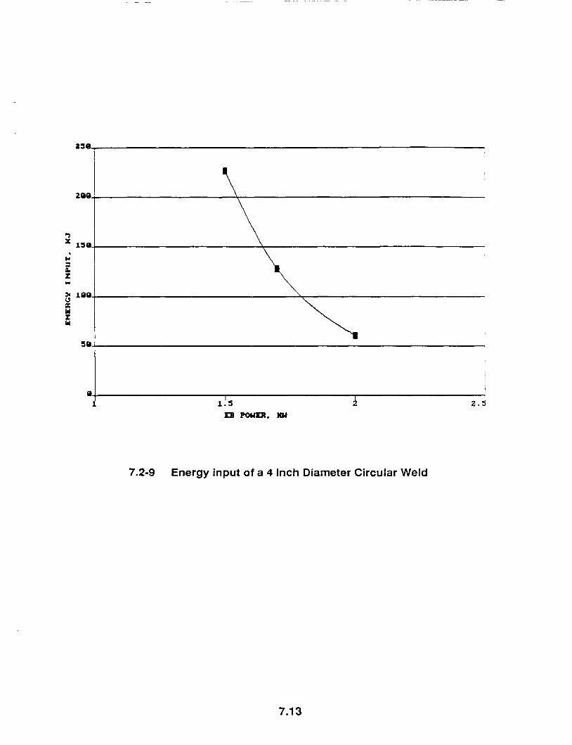
W haz dMll Ein
wj
t
depth of penetration, inch percentage of penetration through the bottom plate weld width at surface of top plate - inch weld width at the interface between two plates - inch minimum width of haz at interface, inch weld aspect ratio referring to interface width energy impact of a 4 inch circular weld, KJ minimum time required to complete a 4 inch circular weld sec
w s wi dfli "HAZ t Ein (inch) (inch) (in/in) (inch) (Sec) ( K J )
1 0.194 55% 0.140 0.050 3.9 0.025 12.6 25.2 2 0.156 25% 0.164 0.042 3.7 0.025 15.1 30.2 3 0.201 61% 0.220 0.076 2.6 0.036 30.2 60.4 4 0.141 13% 0.217 0.030 4.7 0.119 50.3 75.5 5 0.190 52% 0.399 0.194 1.1 0.152 150.8 226.2 6 0.194 55% 0.255 0.121 1.6 0.095 94.2 160.1 7 0.194 55% 0.251 0.114 1.7 0.087 75.4 128.2 8 0.186 49% 0.247 0.106 1.8 0.084 62.8 106.8
%db NO. d (inch)
TABLE 7.2-2 WELD CHARACTERISTICS
7.5
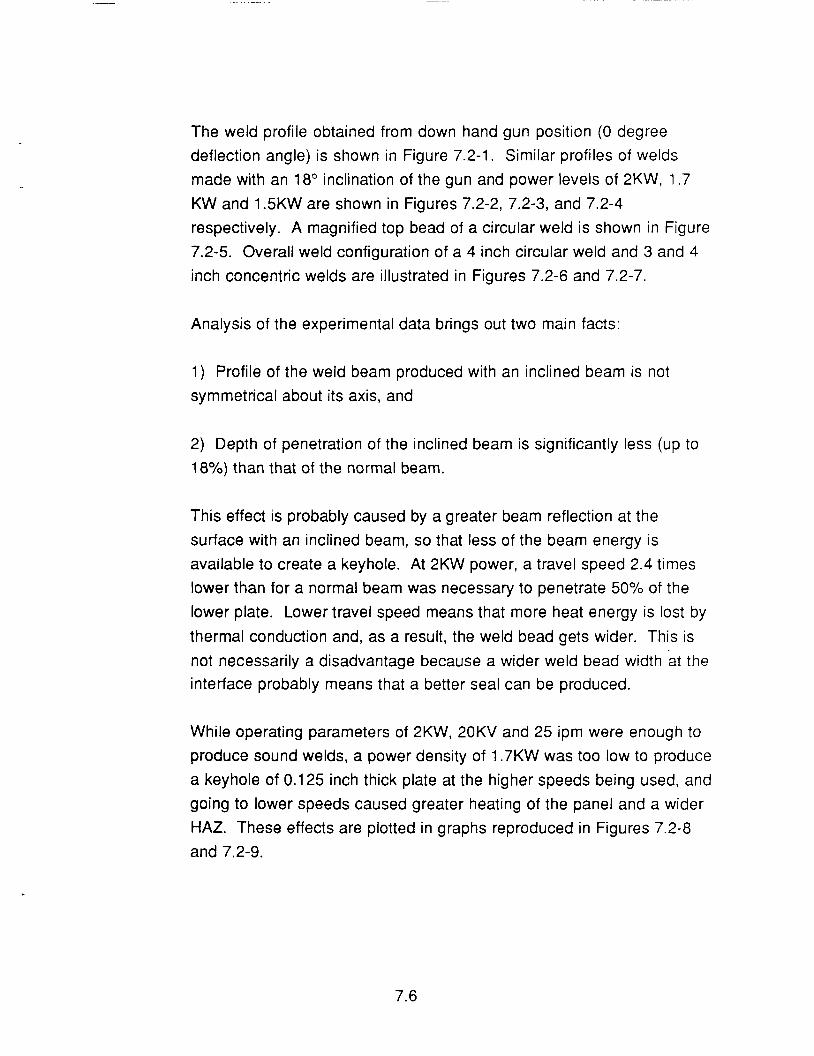
The weld profile obtained from down hand gun position (0 degree deflection angle) is shown in Figure 7.2-1. Similar profiles of welds made with an 18" inclination of the gun and power levels of 2KW, 1.7 KW and 1.5KW are shown in Figures 7.2-2, 7.2-3, and 7.2-4 respectively. A magnified top bead of a circular weld is shown in Figure 7.2-5. Overall weld configuration of a 4 inch circular weld and 3 and 4 inch concentric welds are illustrated in Figures 7.2-6 and 7.2-7.
Analysis of the experimental data brings out two main facts:
1) Profile of the weld beam produced with an inclined beam is not symmetrical about its axis, and
2) Depth of penetration of the inclined beam is significantly less (up to 18%) than that of the normal beam.
This effect is probably caused by a greater beam reflection at the surface with an inclined beam, so that less of the beam energy is available to create a keyhole. At 2KW power, a travel speed 2.4 times lower than for a normal beam was necessary to penetrate 50% of the lower plate. Lower travel speed means that more heat energy is lost by thermal conduction and, as a result, the weld bead gets wider. This is not necessarily a disadvantage because a wider weld bead width at the interface probably means that a better seal can be produced.
While operating parameters of 2KW, 20KV and 25 ipm were enough to produce sound welds, a power density of 1.7KW was too low to produce a keyhole of 0.125 inch thick plate at the higher speeds being used, and going to lower speeds caused greater heating of the panel and a wider HAZ. These effects are plotted in graphs reproduced in Figures 7.2-8 and 7.2-9.
7.6
It is concluded that the experimental results demonstrate the capability of producing the specified circular lap weld at 2KW power, 20KV accelerating voltage, 18" deflection angle, 6 inch work distance, 50 - 100 microtorr vacuum, and a travel speed of 25 ipm. Selection of beam power level significantly affects the weld bead profile and the energy efficiency, and there are obvious advantages to having higher power available in the onorbit EB welding system than the 2KW indicated as the minimum required for the proposed space experiment. Consequently, we plan to study the feasibility of increasing power capability to 3KW in the new EB welding system now under design.
It should be emphasized that, because of the high welding speeds used at 2KW power output, actual welding times will be about 25-30 seconds, and power consumption only 1/60th. of a KWH per weld cycle. Total power consumption for the whole experiment will be less than 1 KWH.
7.7
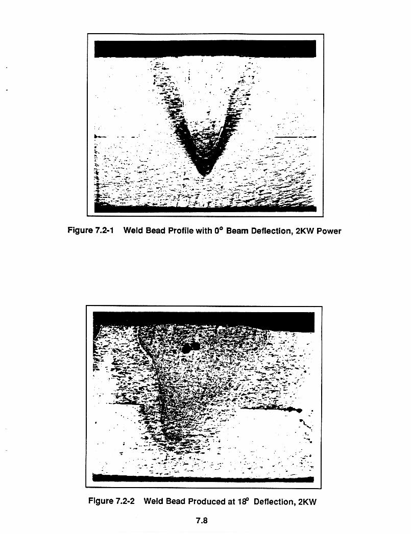
Figure 7.2-1 Weld Bead Profile with 0' Beam Deflection, 2KW Power
Figure 7.2-2 Weld Bead Produced at I€? Deflection, 2KW
7.8 ~~ ~ ~ ~~
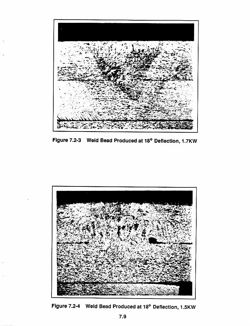
Figure 7.2-3 Weld Bead Produced at 18' Deflection, 1.7KW
I
I
Figure 7.2-4 Weld Bead Produced at 18' Deflection, 1 SKW
7.9
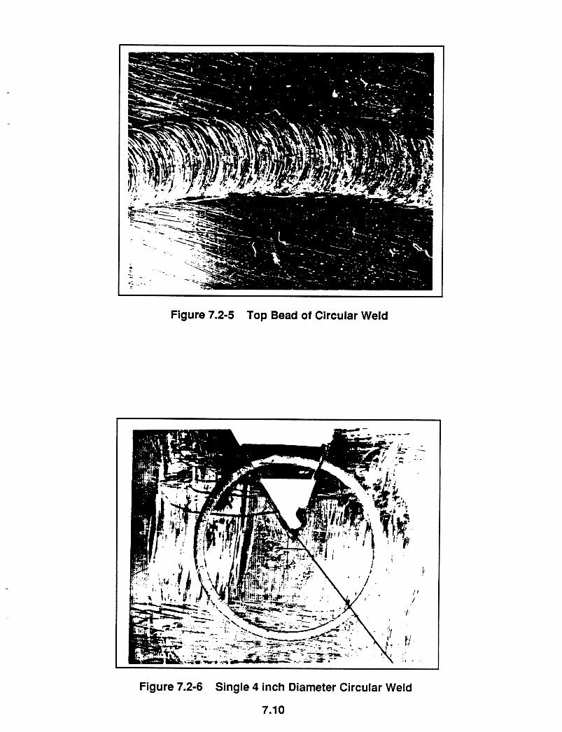
Figure 7.2-5 Top Bead of Circular Weld
I
Figure 7.2-6 Single 4 inch Diameter Circular Weld
7.1 0
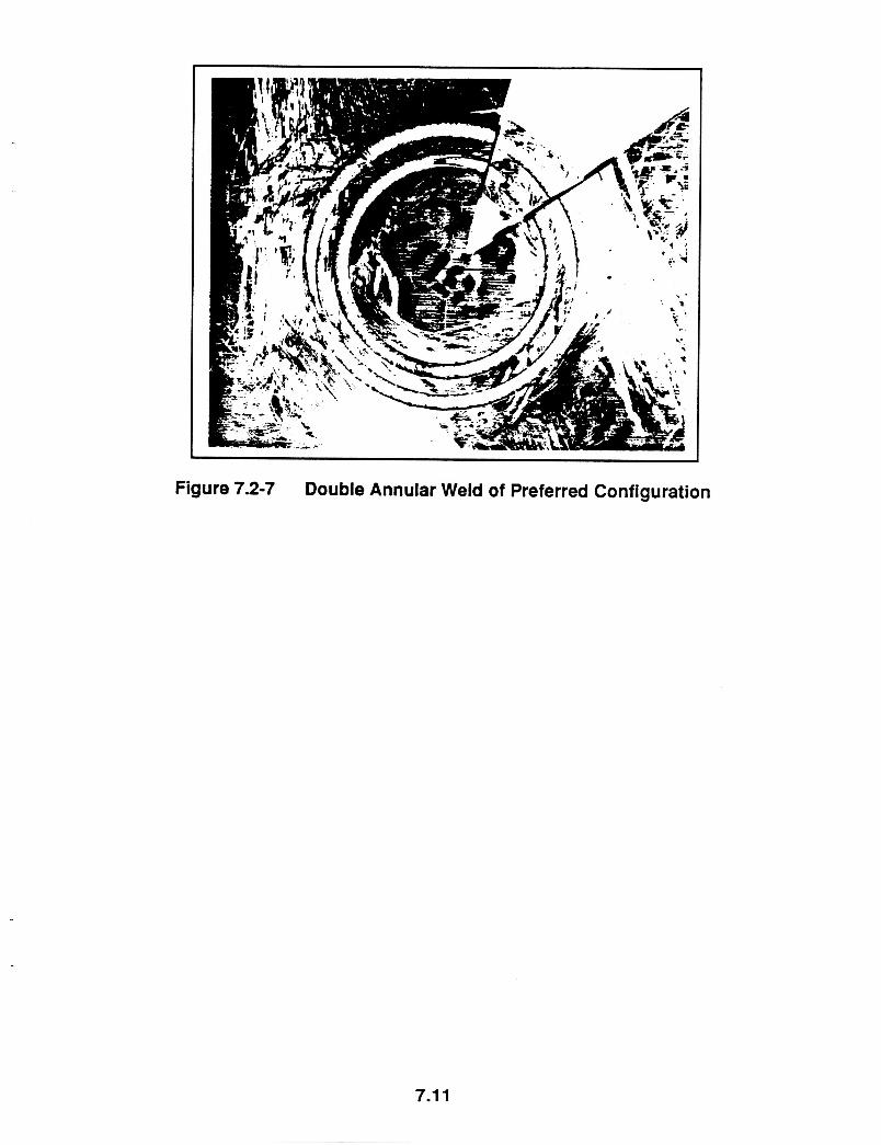
Figure 7.2-7 Double Annular Weld of Preferred Configuration
7.1 1
I h Y I D I H A I SURFACE I
4
X y .3 .I
X c n f . 2 ~ I
.1
0 1
A YIDTH AI INTERFACE A
0 YIDTH AT HAWINTERFACE
I
I I
4 i
I
I
I j
11 5 a 2 . 5
7.2-8 Weld Width vs EB Power
7.1 2
200
. b
2 t I
5 100 p: Y 2 Y
l! s a 2 . 5
7.2-9 Energy input of a 4 Inch Diameter Circular Weld
7.1 3
8.0 OUTLINE fOR DEVELOPING FLIGHT HARDWARE AND SOFTWARE
Requirements for flight hardware and software break down into three categories: the specially designed set of panels that will be welded in the experiment; the EB welding system itself, consisting of E6 gun, high voltage power supply, electrical controls and programmer, weld panel positioner, and self-contained enclosure; and the software for controlling the experiment.
8.1 Weld Panels
The set of six panels, to be provided in duplicate for the ground- produced and onorbit welded series plus a sufficiently large number of spares to permit development of the welding procedures and parameters for the experiment, will be made in the machine shop facility at MAF. Preliminary designs for these panels are described in Section 6
of this report.
8.2 EB Welding System and Software
The onorbit welding system for the proposed experiment has been designed under an IRAD funded by Martin Marietta. This IRAD supports the program to design an onorbit EB welding demonstration experiment funded by NASA contract NAS8-37756. Progress made with the IRAD funded program is briefly reviewed below.
At an early stage in the development of the proposed experiment, discussions were held with the major EB welding equipment suppliers on the feasibility of a number of approaches to the experiment design that were under consideration. In this way we were assured that nothing that was proposed would be beyond the capability of a new EB weld system to perform.
8.0
A request for proposals was then sent to three equipment builders defining the performance criteria and physical characteristics of the onorbit EB welding system required, and asking for proposals on a design meeting all the criteria.
Two of the proposals received were accepted, and subcontracts issued for the production of detailed conceptual designs to Ferranti-Sciaky Inc and Wentgate-Ebtec, Inc.
Ferranti-Sciaky has on its engineering staff the principal designer of the handheld EB welding gun build in 1967 by Hamilton-Standard, and has proposed a new design reminiscent of the main features of this equipment. The Hamilton-Standard system did not include a vacuum- rated, miniaturized power supply or automated controls since this was outside the requirements of the contract. One of the benefits Ferranti- Sciaky now brings to our project is its great expertise in the design of power systems, computerized controls and program software. The Ferranti-Sciaky design is highly professional; some of the subsystems have already been bread-board tested and improvement areas detailed, and the company is poised to move quickly into advanced design, further bread-board testing and final construction phases.
Our other sub-contractor, Wentgate-Ebtec, specializes in the production of small EB welding systems used widely in the electronics and small turbine parts industries. Their proposal was based on modifying one of their existing small systems for onorbit operations, and had the advantage that their design efforts would by mainly directed at space- hardening an already existing system Wentgate-Ebtec are also expert in the area of controls, automation and software based on the use of microcomputers, and their total design concept has considerable merit.
8.1
We plan to complete discussions with our two subcontractors and be in a position to pick the system best suited to our requirements in November 1989, using a selection team composed of metallurgy, welding, computer controls and software, and automation experts drawn from Martin's various manufacturing divisions and Martin Marietta Laboratory .
In the execution of a Phase B contract leading to the flight experiment, Martin Marietta would form a team of engineers having the appropriate engineering, computer and electronics skills to monitor the work of the selected subcontractor for the whole period for performance. Martin Marietta is very familiar with NASA procedures and requirements leading up to a flight experiment, and will appoint a qualified program manager to direct the overall performance of the project and the individual activities of the selected technical specialists who will interface with the vendor and with NASA flight preparation personnel.
Our preliminary assessment of the tasks involved in the performance of Phase B of the onorbit EB weld repair demonstration experiment and the overall schedule for completion of these tasks is defined in the next section of this report, together with a rough estimate of the cost of preparing and performing the experiment.
8.2
9.0 INITIAL ASSESSMENT OF THE DEVELOPMENT COSTS AND SCHEDULES
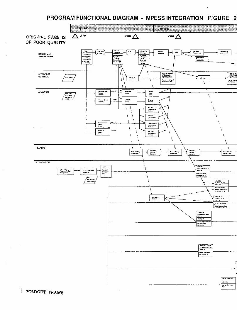
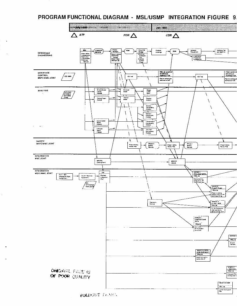
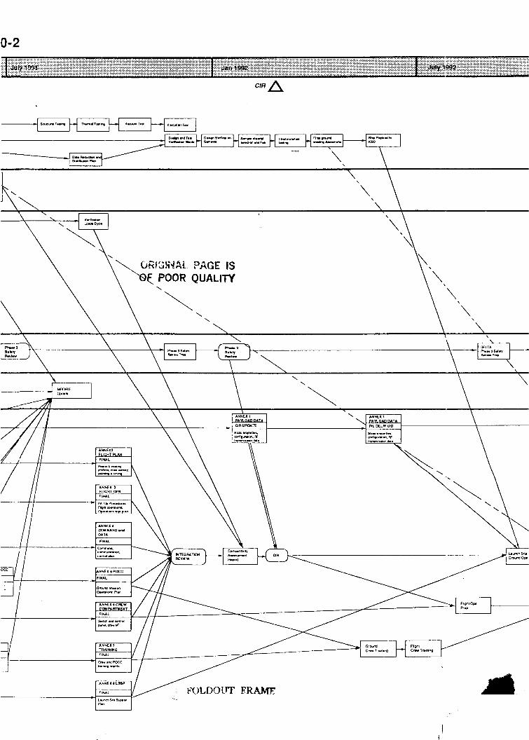
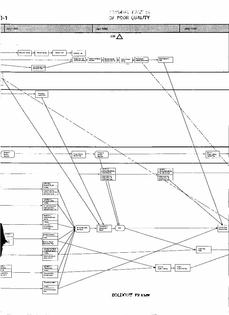
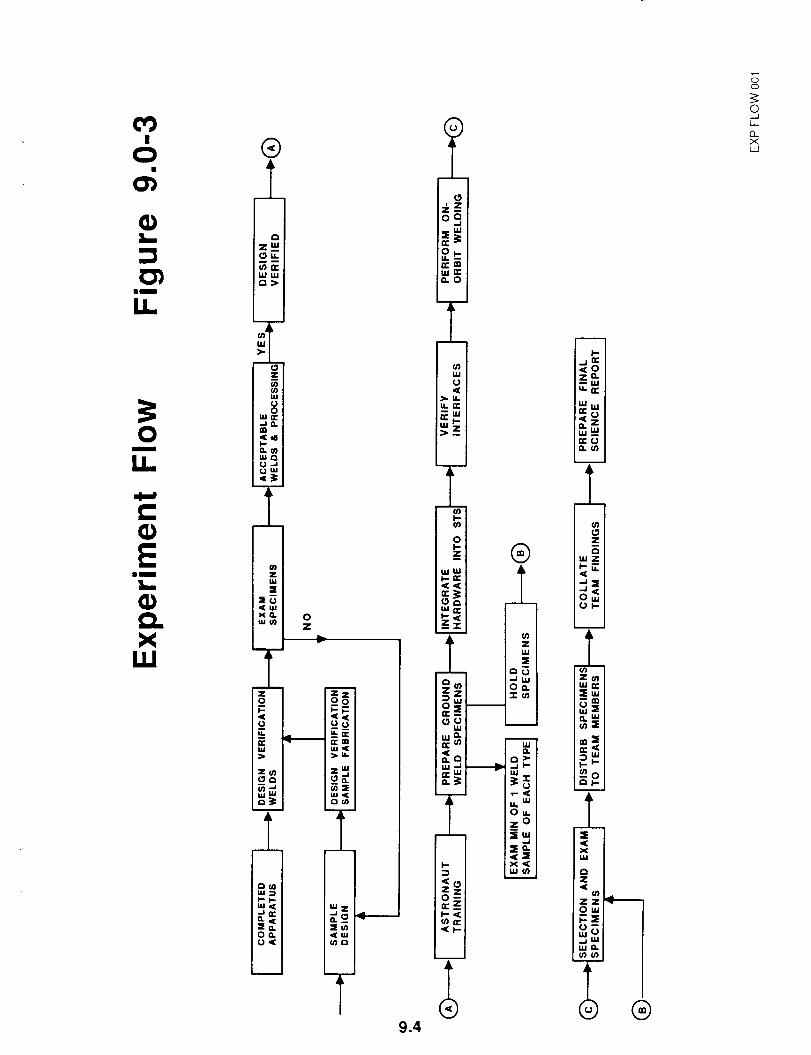
We have made a first estimate of the cost of developing the proposed experiment on the basis of the tasks and procedures set out in the flow diagrams, Figures 9.0 to 5.
Figure 9.0-1 is the program functional diagram based on integrating the welding system into the MPESS facilities of the orbiter, while Figure 9.0-2 assumes use of the MSN/USMP integration arrangements. We have arbitrarily selected a July 1990 ATP date in evolving the three year schedules illustrated in the two charts.
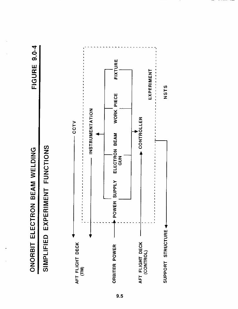
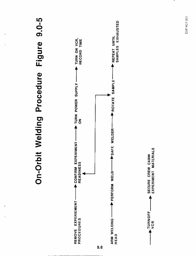
Figure 9.0-3 is a simplified block diagram showing the experiment flow from the point at which the EB welding system is delivered by the vendor The simplified experiment functions are illustrated in Figure 9.0-4, and the actual on-orbit welding procedure is summarized in Figure 9.0-5.
Our cost estimate assumes a Program Manager will direct the Phase B work in a 75 percent capacity for the duration of the program. The Program Manager will have a team of three engineers to assist him, each contributing half his time to the project. A safety engineering specialist will contribute six to seven man-months, or roughly one quarter of his time, to the later stages of the project. Other costs will be incurred in use of materials, travel and sub-contracts to buy EB welding services and weld specimen examination and characterization services.
9.0
We have estimated the period of performance for the proposed experiment to be thirty-six months. Total cost of the experiment is comprised of two elements:
1) Cost of managing, developing and executing the flight experiment, and of metallurgical characterization of the welded specimens, and
2) Cost of designing, building and qualifying the E 6 welding equipment to perform the experiment.
Using the program development plan detailed in Figure 9.0-1 we have allocated anticipated charges for the labor, material and subcontracts, and travel required to complete all the tasks outlined in the plan, and are satisfied that we can complete the proposed experiment within the price ranges listed in the table below. All prices are fully burdened and included a fee.
Cost of equipment, on the other hand, is less reliable because we have used estimates presented by two subcontractors in response to a solicitation we released in March 1989. More accurate estimates for the cost of equipment will be forthcoming at the end of October 1989, when the contractors present their final reports and completed conceptual designs.
9.1
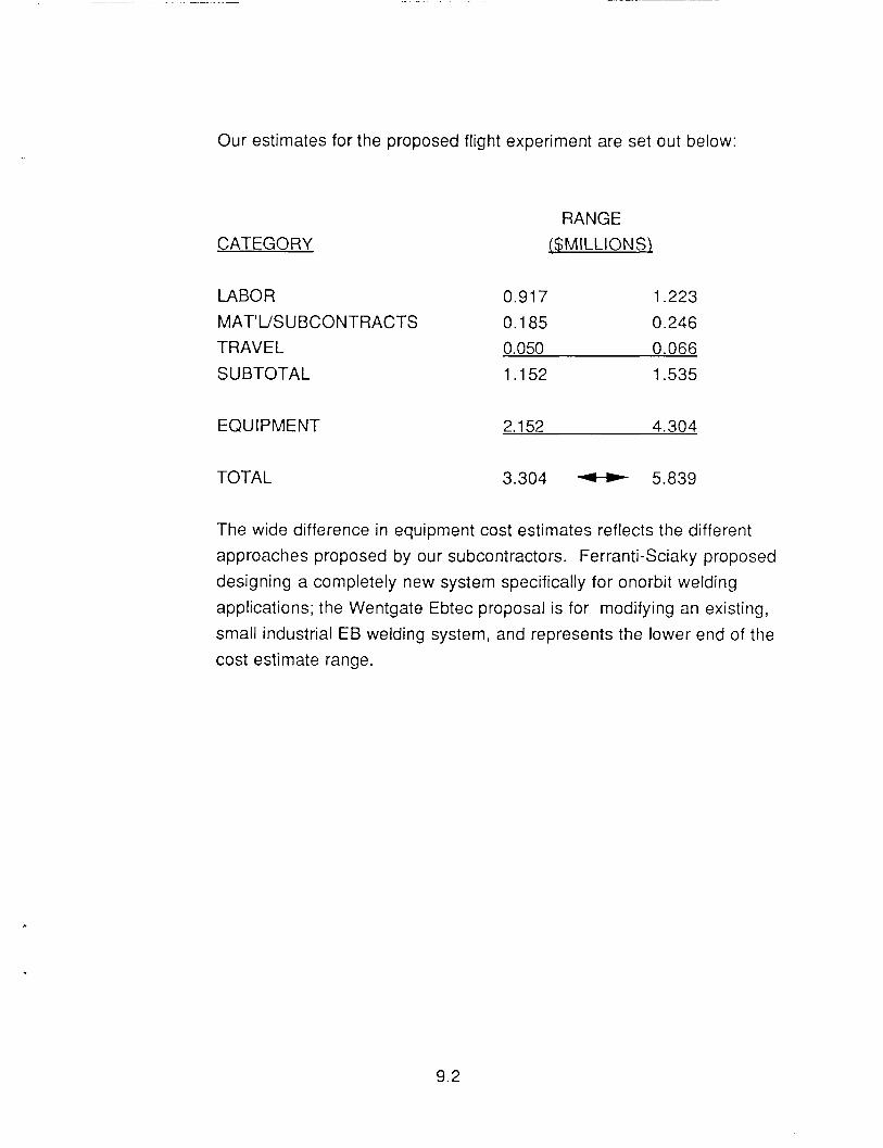
Our estimates for the proposed flight experiment are set out below:
CATEGORY RANGE
{$MILLIONS\
LABOR 0.91 7 1.223 MAT'USUBCONTRACTS 0.1 85 0.246 TRAVEL 0.050 0.066 SUBTOTAL 1.152 1.535
EQUIPMENT 2.152 4.304
TOTAL 3.304 5.839
The wide difference in equipment cost estimates reflects the different approaches proposed by our subcontractors. Ferranti-Sciaky proposed designing a completely new system specifically for onorbit welding applications; the Wentgate Ebtec proposal is for modifying an existing, small industrial EB welding system, and represents the lower end of the cost estimate range.
9.2
PROGRAM FUNCTIONAL DIAGRAM - MPESS INTEGRATION FIGURE 9
A ATP OR;GjrlkL PAGE IS OF POOR QUALITY
CDR A
DESIGN nd ENGINEERING
PROGRAM FUNCTIONAL DIAGRAM - MSLNSMP INTEGRATION FIGURE 9,
DEUGN nd ENGINEERING
INTERFACE - CONTROL MSFUMMC JOINT
U
ANALYSIS /&g
. -
I 1 \ I \ , I I \
(IMun emu. ud Y d \ I I \
\ F.LI.n *m
I I
' \ \ \ \
\ I I \
I \
\
\
INTEGRATDN MMC JOINT
0-2
7
0 0
Q) L
U
0 L I c Q)
E m- L Q) Q X W
W Z
f
T 1
a
-L
1 t X w
9.4
. . . . . . . . . . . . . . . . . . . . . . . . I I
I I 1 1 I I 1 I I I I I
1 1 1
1 I I I 1
I 1 1
1 I I 1 1
t
I I I
1
I I I I I I I I I I I I
I
I
I
I I
I I
1 I 1 I I c a \ I - r a ‘ Z
W K 3 + x LL -
W o W - I n
I- z - K W
X W
n I
I I I I
I I
E : 0 1 o b
I I
I I
I I I I
1 I
I
1
I z 0 I-
I- z
- a
Y K
P K W 4 -I .O U I- Z 0 o
K I- in z
W K 3 c
Y 0 W P
K
0 s n
l- a I- I I-
K 0
3 a
n n I--
a L t a K 0
9.5
7
0 0 L P
W
a X Lu
Ci-W
> F 0 5 Q)
L 3 cn L W
U t Q) L
Ib Q)
Q n a
0 0 2
w I-
I- O K
a
C m- t a
W P d z W cn
w m- a 6 k 0
t t t LL LL 0 z a u 30 I-> d
W
% W Q > w 0 0 5 0 w a a n
I U a w a x
9.6
REFERENCES
. 1. Harry G Lienau, J. F. Lowry and C.B. Hasson, "Electron Beam Welder for Use in Space", Westinghouse Engineer, March 1968. 2. R. E. Montoe, "Characterization of Metals Meltina Discs: Skvlab Exoeriment: M551 'IL NASA Contractor Report NAS8-28725, R. E. Monroe, December 4, 1973. 3. F. R. Schollhammer, "Hand-Held Electron Beam Gun for In-%ace Weldinq", Fourth Space Congress, April 1967. 4. N. C. Elfer, "Space Debris and Meteroid Protection", Martin Marietta Michoud Aerospace Report No. 87-47501, December 1985. 5. W. T. Randolph, IR&D M-56R: Onorbit Weldina and Cuttinq, Martin Marietta Michoud Aerospace Report No. 85-47656-001, December 1985. 6. Harry S. Haber and Alberta Quinn, "Makina Onorbit Structural ReDairs to
SDace Station", Aerospace Engineering, August 1989.
10.0