Embed Size (px)
Citation preview
IEEE TRANSACTIONS ON SIGNAL PROCESSING, VOL. 50, NO. 6, JUNE 2002 1277
Contour-Shape Based Reconstruction of Fragmented,1600 B.C. Wall Paintings
Constantin Papaodysseus, Thanasis Panagopoulos, Michael Exarhos, Constantin Triantafillou, Dimitrios Fragoulis,and Christos Doumas
Abstract—In this paper, a novel general methodology is intro-duced for the computer-aided reconstruction of the magnificentwall paintings of the Greek island Thera (Santorini), which werepainted in the middle of the second millennium B.C. These wallpaintings have been excavated in fragments, and as a result, theirreconstruction is a painstaking and a time-consuming process.Therefore, in order to facilitate and expedite this process, a propersystem has been developed based on the introduced methodology.According to this methodology, each fragment is photographed,its picture is introduced to the computer, its contour is obtained,and, subsequently, all of the fragments contours are comparedin a manner proposed herein. Both the system and the method-ology presented here extract the maximum possible informationfrom the contour shape of fragments of an arbitrary initiallyunbroken plane object to point out possible fragment matching.This methodology has been applied to two excavated fragmentedwall paintings consisting of 262 fragments with full success, butmost important, it has been used to reconstruct, for the first time,unpublished parts of wall paintings from a set of 936 fragments.
I. INTRODUCTION-PROBLEM DESCRIPTION
T HE DISCOVERY of the wall paintings at Akrotiri onthe Greek island Thera (Santorini) is of outstanding
importance for human knowledge of the early Aegean world.According to prominent archaeologists, these wall paintingsrank alongside the greatest archaeological discoveries. Thelate Prof. Marinatos originated the excavations, which havebeen successfully continued by Prof. C. Doumas. As withthe treasures of Pompeii and Herculaneum, the wall paintingsof Thera were preserved due to the seal of the pumice fromthe eruption of a volcano [1]. As a rule, walls decorated withpaintings no longer survive. They collapsed together withtheir painted coat before the volcanic eruption, due to partic-ularly strong earthquakes. Thus, a single painting is usuallyscattered into many fragments mixed with the fragments ofother wall paintings. The restoration of the wall paintingsfrom the fragments is a very painstaking and time-consumingprocess, frequently demanding many months or even yearsof dedicated, experienced personnel work for a single wallpainting restoration. Therefore, the development of a systemthat will contribute to the automatic restoration of these wall
Manuscript received May 16, 2001; revised February 11, 2002. The associateeditor coordinating the review of this paper and approving it for publication wasDr. Hamid Krim.
C. Papaodysseus, Th. Panagopoulos, M. Exarhos, C. Triantafillou, andD. Fragoulis are with the Department of Electrical and Computer Engineering,Division of Computer Science, National Technical University of Athens,Athens, Greece (e-mail: [email protected]).
C. Doumas is with the National University of Athens, Akrotiri Excavations,Thera, Greece.
Publisher Item Identifier S 1053-587X(02)04395-7.
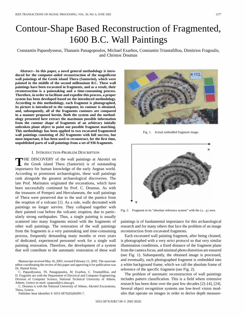
Fig. 1. Actual embedded fragment image.
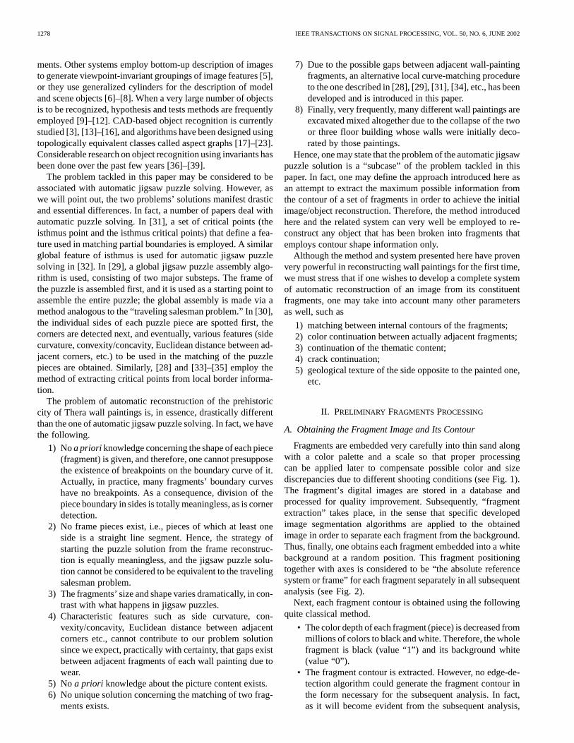
Fig. 2. Fragment in its “absolute reference system” with the(x; y) axes.
paintings is of fundamental importance for this archaeologicalresearch and for many others that face the problem of an imagereconstruction from excavated fragments.
Each excavated wall painting fragment, after being cleaned,is photographed with a very strict protocol so that very similarillumination conditions, a fixed distance of the fragment planefrom the camera focus, and minimal photo distortion are ensured(see Fig. 1). Subsequently, the obtained image is processed,and eventually, each photographed fragment is embedded intoa white background frame, which we call the absolute frame ofreference of the specific fragment (see Fig. 2).
The problem of automatic reconstruction of wall paintingsincludes pattern classification. This is a field where extensiveresearch has been done over the past few decades [2]–[4], [24].Several object recognition systems use low-level vision mod-ules that operate on images in order to derive depth measure-
1053-587X/02$17.00 © 2002 IEEE
1278 IEEE TRANSACTIONS ON SIGNAL PROCESSING, VOL. 50, NO. 6, JUNE 2002
ments. Other systems employ bottom-up description of imagesto generate viewpoint-invariant groupings of image features [5],or they use generalized cylinders for the description of modeland scene objects [6]–[8]. When a very large number of objectsis to be recognized, hypothesis and tests methods are frequentlyemployed [9]–[12]. CAD-based object recognition is currentlystudied [3], [13]–[16], and algorithms have been designed usingtopologically equivalent classes called aspect graphs [17]–[23].Considerable research on object recognition using invariants hasbeen done over the past few years [36]–[39].
The problem tackled in this paper may be considered to beassociated with automatic jigsaw puzzle solving. However, aswe will point out, the two problems’ solutions manifest drasticand essential differences. In fact, a number of papers deal withautomatic puzzle solving. In [31], a set of critical points (theisthmus point and the isthmus critical points) that define a fea-ture used in matching partial boundaries is employed. A similarglobal feature of isthmus is used for automatic jigsaw puzzlesolving in [32]. In [29], a global jigsaw puzzle assembly algo-rithm is used, consisting of two major substeps. The frame ofthe puzzle is assembled first, and it is used as a starting point toassemble the entire puzzle; the global assembly is made via amethod analogous to the “traveling salesman problem.” In [30],the individual sides of each puzzle piece are spotted first, thecorners are detected next, and eventually, various features (sidecurvature, convexity/concavity, Euclidean distance between ad-jacent corners, etc.) to be used in the matching of the puzzlepieces are obtained. Similarly, [28] and [33]–[35] employ themethod of extracting critical points from local border informa-tion.
The problem of automatic reconstruction of the prehistoriccity of Thera wall paintings is, in essence, drastically differentthan the one of automatic jigsaw puzzle solving. In fact, we havethe following.
1) Noa priori knowledge concerning the shape of each piece(fragment) is given, and therefore, one cannot presupposethe existence of breakpoints on the boundary curve of it.Actually, in practice, many fragments’ boundary curveshave no breakpoints. As a consequence, division of thepiece boundary in sides is totally meaningless, as is cornerdetection.
2) No frame pieces exist, i.e., pieces of which at least oneside is a straight line segment. Hence, the strategy ofstarting the puzzle solution from the frame reconstruc-tion is equally meaningless, and the jigsaw puzzle solu-tion cannot be considered to be equivalent to the travelingsalesman problem.
3) The fragments’ size and shape varies dramatically, in con-trast with what happens in jigsaw puzzles.
4) Characteristic features such as side curvature, con-vexity/concavity, Euclidean distance between adjacentcorners etc., cannot contribute to our problem solutionsince we expect, practically with certainty, that gaps existbetween adjacent fragments of each wall painting due towear.
5) No a priori knowledge about the picture content exists.6) No unique solution concerning the matching of two frag-
ments exists.
7) Due to the possible gaps between adjacent wall-paintingfragments, an alternative local curve-matching procedureto the one described in [28], [29], [31], [34], etc., has beendeveloped and is introduced in this paper.
8) Finally, very frequently, many different wall paintings areexcavated mixed altogether due to the collapse of the twoor three floor building whose walls were initially deco-rated by those paintings.
Hence, one may state that the problem of the automatic jigsawpuzzle solution is a “subcase” of the problem tackled in thispaper. In fact, one may define the approach introduced here asan attempt to extract the maximum possible information fromthe contour of a set of fragments in order to achieve the initialimage/object reconstruction. Therefore, the method introducedhere and the related system can very well be employed to re-construct any object that has been broken into fragments thatemploys contour shape information only.
Although the method and system presented here have provenvery powerful in reconstructing wall paintings for the first time,we must stress that if one wishes to develop a complete systemof automatic reconstruction of an image from its constituentfragments, one may take into account many other parametersas well, such as
1) matching between internal contours of the fragments;2) color continuation between actually adjacent fragments;3) continuation of the thematic content;4) crack continuation;5) geological texture of the side opposite to the painted one,
etc.
II. PRELIMINARY FRAGMENTS PROCESSING
A. Obtaining the Fragment Image and Its Contour
Fragments are embedded very carefully into thin sand alongwith a color palette and a scale so that proper processingcan be applied later to compensate possible color and sizediscrepancies due to different shooting conditions (see Fig. 1).The fragment’s digital images are stored in a database andprocessed for quality improvement. Subsequently, “fragmentextraction” takes place, in the sense that specific developedimage segmentation algorithms are applied to the obtainedimage in order to separate each fragment from the background.Thus, finally, one obtains each fragment embedded into a whitebackground at a random position. This fragment positioningtogether with axes is considered to be “the absolute referencesystem or frame” for each fragment separately in all subsequentanalysis (see Fig. 2).
Next, each fragment contour is obtained using the followingquite classical method.
• The color depth of each fragment (piece) is decreased frommillions of colors to black and white. Therefore, the wholefragment is black (value “1”) and its background white(value “0”).
• The fragment contour is extracted. However, no edge-de-tection algorithm could generate the fragment contour inthe form necessary for the subsequent analysis. In fact,as it will become evident from the subsequent analysis,
PAPAODYSSEUSet al.: CONTOUR-SHAPE BASED RECONSTRUCTION OF WALL PAINTINGS 1279
in order that the introduced methodology is applied, eachcontour must have the following properties.
a) Each pixel must have exactly two neighboringpixels.
b) No isolated pixels or groups of pixels are allowed.c) Three pixels must not form a compact right (90)
angle.Therefore, software must be developed to guarantee this formof the contour.
B. Obtaining Rotated Contours to Cope With RandomFragment Orientation
Consider two actually adjacent fragments. Since their orien-tation in their absolute frame of reference is completely random,it follows that in order to make them match, one must performa random rotation to at least one of them. In order to accountfor this random rotation, the contours of each fragment are builtcorresponding to all fragment orientations obtained after re-peated rotation of degrees. To set ideas, if one chooses
, then one must perform 360 rotations to the ini-tially obtained contour around the origin of axes of the absoluteframe of reference, thus obtaining 360 contours for each frag-ment. Notice that clearly, since each fragment can be consideredas a rigid body, rotation around another center is a compositionof a parallel translation and rotation around the axes origin. Ofcourse, rotation around the origin by an anglemoves point
into via
(1)
Direct application of this formula leads to contours violatingthe three demands a)–c), stated in Section II-A. In order to cir-cumvent this, a “virtual” refinement of all pixels has been gen-erated, creating a denser grid, and rotation has been applied toit. Subsequently, to the resulting images, contours satisfying thedemands above have been obtained by applying developed ded-icated software.
C. Dividing the Contour Into Blocks
Subsequently, the obtained contour is divided into blocks asfollows.
A 3 3 pixels frame (mask) is shifted throughout the wholecontour so that each time, a pixel of the contour is the centerof this mask. As usual, each square of the mask is labeled asshown in Fig. 3(a). This mask is used to enumerate the pixels ofthe contour as follows.
Each fragment contour frame is swept horizontally until thefirst contour pixel is encountered. This is the first pixel to be-come center of the 3 3 frame. The pixel (1 or 2) of the 3 3mask that is “occupied” (i.e., it belongs to the fragment contour)is unambiguously the next #2 pixel in the clockwise sense. Sub-sequently, the #2 pixel becomes the center of the 33 mask.The pixel of the mask that is occupied by a contour pixel, otherthan pixel #1, becomes pixel #3, and so forth.
Next, using the pixel enumeration in the clockwise sense, thefragment contour is divided into blocks in the following way(see Fig. 3). Pixels #1 and #2 belong to the first block. If pixel
Fig. 3. (a) Indexing the pixels of the 3� 3 mask. (b) Depiction of absoluteangles of all pixels of the 3� 3 mask with the center pixel C. C is the centerpixel of the mask that belongs to the contour.
Fig. 4. Block number 1: Pixels #1, #2, and #3. Block Number 2: Pixels #4,#5, #6, #7, and #8. Block number 3: Pixels #9, #10, and #11. Pixel #12 is thebeginning of Block number 4.
#3 is collinear with #1 and #2, i.e., if all three pixels are on thesquares of the 3 3 mask labeled 6, C, 2, or 5, C, 1, and if #2,#3, and #4 pixels are collinear as well, then pixel #3 belongs toblock #1.
A block changes at the first pixel where the #( ) contourpixel, # itself and the #( ) contour pixel are not collinear.Notice that the first pixel of each block might as well have be-longed to the previous block (for example, in Fig. 4, pixel #4might belong to block number 1 and 2, whereas pixel #9 mightbelong to block number 2 and 3). However, in this methodology,it will be mainly considered that each such a pixel will be thefirst pixel of the block with the greater cardinal number. Eachtime that a block changes, say, at pixel #, the relative angleis defined between the present and the next block as the uniqueconvex angle of the #( ) contour pixel with respect to the#( ) contour pixel, according to the convention of absoluteangles of all pixels of the 3 3 mask with the center pixel C, asshown in Fig. 3(b). Besides, it is useful for the applied methodto define the absolute, so to say, angle of each block, which isthe angle the block makes with the axes of the fragmentabsolute frame of reference.
The block construction procedure ends when all contourpixels have been allocated to a block.
III. A CTUAL METHOD OFSPOTTINGMATCHING FRAGMENTS
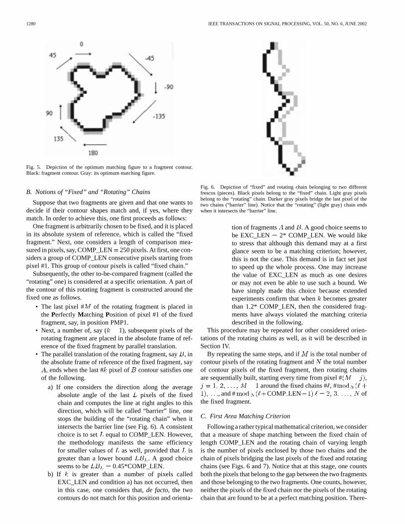
A. Defining the Optimum Matching Parameters
One of the two fragments contours is arbitrarily considered tobe fixed, and by convention, the optimum matching figure to thiscontour is defined (see Fig. 5). In fact, to each pixel of the fixedfragment, its perfectly matching pixel corresponds, as shown inFig. 5. It should be emphasized that the first pixel of each blockhas two matching pixels since for this, and only this, application,the first pixel of the block number is also considered to belongto the block number ( ).
1280 IEEE TRANSACTIONS ON SIGNAL PROCESSING, VOL. 50, NO. 6, JUNE 2002
Fig. 5. Depiction of the optimum matching figure to a fragment contour.Black: fragment contour. Gray: its optimum matching figure.
B. Notions of “Fixed” and “Rotating” Chains
Suppose that two fragments are given and that one wants todecide if their contour shapes match and, if yes, where theymatch. In order to achieve this, one first proceeds as follows:
One fragment is arbitrarily chosen to be fixed, and it is placedin its absolute system of reference, which is called the “fixedfragment.” Next, one considers a length of comparison mea-sured in pixels, say, COMP_LEN250 pixels. At first, one con-siders a group of COMP_LEN consecutive pixels starting frompixel #1. This group of contour pixels is called “fixed chain.”
Subsequently, the other to-be-compared fragment (called the“rotating” one) is considered at a specific orientation. A part ofthe contour of this rotating fragment is constructed around thefixed one as follows.
• The last pixel # of the rotating fragment is placed inthe Perfectly MatchingPosition of pixel #1 of the fixedfragment, say, in position PMP1.
• Next, a number of, say ( ), subsequent pixels of therotating fragment are placed in the absolute frame of ref-erence of the fixed fragment by parallel translation.
• The parallel translation of the rotating fragment, say, inthe absolute frame of reference of the fixed fragment, say
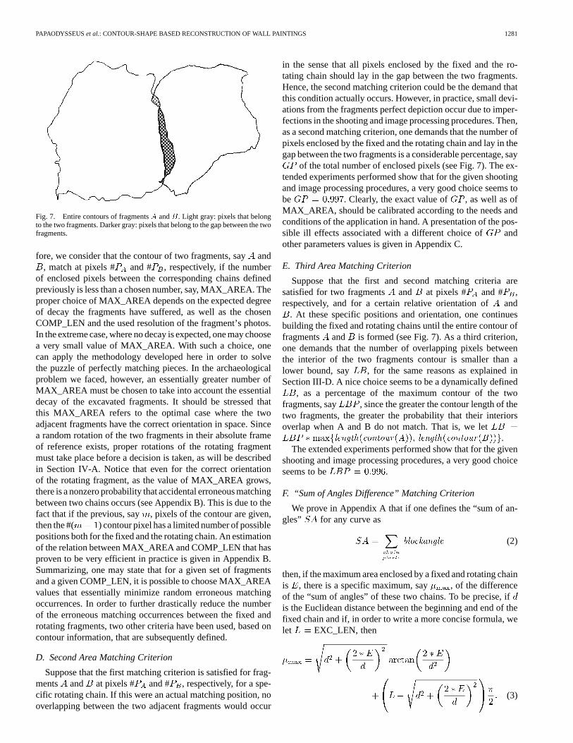
, ends when the last #pixel of contour satisfies oneof the following.
a) If one considers the direction along the averageabsolute angle of the last pixels of the fixedchain and computes the line at right angles to thisdirection, which will be called “barrier” line, onestops the building of the “rotating chain” when itintersects the barrier line (see Fig. 6). A consistentchoice is to set equal to COMP_LEN. However,the methodology manifests the same efficiencyfor smaller values of as well, provided that isgreater than a lower bound . A good choiceseems to be 0.45*COMP_LEN.
b) If is greater than a number of pixels calledEXC_LEN and condition a) has not occurred, thenin this case, one considers that,de facto, the twocontours do not match for this position and orienta-
Fig. 6. Depiction of “fixed” and rotating chain belonging to two differentfrescos (pieces). Black pixels belong to the “fixed” chain. Light gray pixelsbelong to the “rotating” chain. Darker gray pixels bridge the last pixel of thetwo chains (“barrier” line). Notice that the “rotating” (light gray) chain endswhen it intersects the “barrier” line.
tion of fragments and . A good choice seems tobe EXC_LEN 2* COMP_LEN. We would liketo stress that although this demand may at a firstglance seem to be a matching criterion; however,this is not the case. This demand is in fact set justto speed up the whole process. One may increasethe value of EXC_LEN as much as one desiresor may not even be able to use such a bound. Wehave simply made this choice because extendedexperiments confirm that when becomes greaterthan 1.2* COMP_LEN, then the considered frag-ments have always violated the matching criteriadescribed in the following.
This procedure may be repeated for other considered orien-tations of the rotating chains as well, as it will be described inSection IV.
By repeating the same steps, and ifis the total number ofcontour pixels of the rotating fragment andthe total numberof contour pixels of the fixed fragment, then rotating chainsare sequentially built, starting every time from pixel # ,
around the fixed chains #, #, and # COMP LEN of
the fixed fragment.
C. First Area Matching Criterion
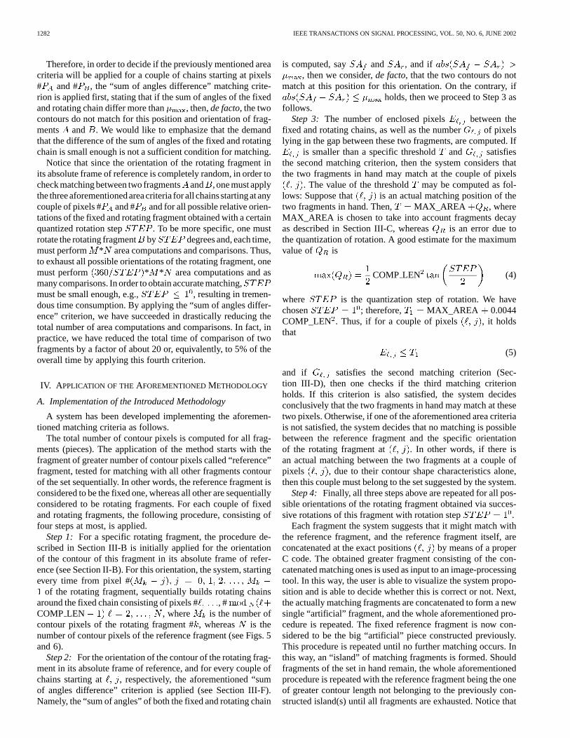
Following a rather typical mathematical criterion, we considerthat a measure of shape matching between the fixed chain oflength COMP_LEN and the rotating chain of varying lengthis the number of pixels enclosed by those two chains and thechain of pixels bridging the last pixels of the fixed and rotatingchains (see Figs. 6 and 7). Notice that at this stage, one countsboth the pixels that belong to the gap between the two fragmentsand those belonging to the two fragments. One counts, however,neither the pixels of the fixed chain nor the pixels of the rotatingchain that are found to be at a perfect matching position. There-
PAPAODYSSEUSet al.: CONTOUR-SHAPE BASED RECONSTRUCTION OF WALL PAINTINGS 1281
Fig. 7. Entire contours of fragmentsA andB. Light gray: pixels that belongto the two fragments. Darker gray: pixels that belong to the gap between the twofragments.
fore, we consider that the contour of two fragments, sayand, match at pixels # and # , respectively, if the number
of enclosed pixels between the corresponding chains definedpreviously is less than a chosen number, say, MAX_AREA. Theproper choice of MAX_AREA depends on the expected degreeof decay the fragments have suffered, as well as the chosenCOMP_LEN and the used resolution of the fragment’s photos.In the extreme case, where no decay is expected, one may choosea very small value of MAX_AREA. With such a choice, onecan apply the methodology developed here in order to solvethe puzzle of perfectly matching pieces. In the archaeologicalproblem we faced, however, an essentially greater number ofMAX_AREA must be chosen to take into account the essentialdecay of the excavated fragments. It should be stressed thatthis MAX_AREA refers to the optimal case where the twoadjacent fragments have the correct orientation in space. Sincea random rotation of the two fragments in their absolute frameof reference exists, proper rotations of the rotating fragmentmust take place before a decision is taken, as will be describedin Section IV-A. Notice that even for the correct orientationof the rotating fragment, as the value of MAX_AREA grows,there is a nonzero probability that accidental erroneous matchingbetween two chains occurs (see Appendix B). This is due to thefact that if the previous, say , pixels of the contour are given,then the #( ) contour pixel has a limited number of possiblepositions both for the fixed and the rotating chain. An estimationof the relation between MAX_AREA and COMP_LEN that hasproven to be very efficient in practice is given in Appendix B.Summarizing, one may state that for a given set of fragmentsand a given COMP_LEN, it is possible to choose MAX_AREAvalues that essentially minimize random erroneous matchingoccurrences. In order to further drastically reduce the numberof the erroneous matching occurrences between the fixed androtating fragments, two other criteria have been used, based oncontour information, that are subsequently defined.
D. Second Area Matching Criterion
Suppose that the first matching criterion is satisfied for frag-ments and at pixels # and # , respectively, for a spe-cific rotating chain. If this were an actual matching position, nooverlapping between the two adjacent fragments would occur
in the sense that all pixels enclosed by the fixed and the ro-tating chain should lay in the gap between the two fragments.Hence, the second matching criterion could be the demand thatthis condition actually occurs. However, in practice, small devi-ations from the fragments perfect depiction occur due to imper-fections in the shooting and image processing procedures. Then,as a second matching criterion, one demands that the number ofpixels enclosed by the fixed and the rotating chain and lay in thegap between the two fragments is a considerable percentage, say
of the total number of enclosed pixels (see Fig. 7). The ex-tended experiments performed show that for the given shootingand image processing procedures, a very good choice seems tobe . Clearly, the exact value of , as well as ofMAX_AREA, should be calibrated according to the needs andconditions of the application in hand. A presentation of the pos-sible ill effects associated with a different choice of andother parameters values is given in Appendix C.
E. Third Area Matching Criterion
Suppose that the first and second matching criteria aresatisfied for two fragments and at pixels # and # ,respectively, and for a certain relative orientation ofand
. At these specific positions and orientation, one continuesbuilding the fixed and rotating chains until the entire contour offragments and is formed (see Fig. 7). As a third criterion,one demands that the number of overlapping pixels betweenthe interior of the two fragments contour is smaller than alower bound, say , for the same reasons as explained inSection III-D. A nice choice seems to be a dynamically defined
, as a percentage of the maximum contour of the twofragments, say , since the greater the contour length of thetwo fragments, the greater the probability that their interiorsoverlap when A and B do not match. That is, we let
length contour A length contour B .The extended experiments performed show that for the given
shooting and image processing procedures, a very good choiceseems to be .
F. “Sum of Angles Difference” Matching Criterion
We prove in Appendix A that if one defines the “sum of an-gles” for any curve as
blockangle (2)
then, if the maximum area enclosed by a fixed and rotating chainis , there is a specific maximum, say , of the differenceof the “sum of angles” of these two chains. To be precise, ifis the Euclidean distance between the beginning and end of thefixed chain and if, in order to write a more concise formula, welet EXC_LEN, then
(3)
1282 IEEE TRANSACTIONS ON SIGNAL PROCESSING, VOL. 50, NO. 6, JUNE 2002
Therefore, in order to decide if the previously mentioned areacriteria will be applied for a couple of chains starting at pixels# and # , the “sum of angles difference” matching crite-rion is applied first, stating that if the sum of angles of the fixedand rotating chain differ more than , then,de facto, the twocontours do not match for this position and orientation of frag-ments and . We would like to emphasize that the demandthat the difference of the sum of angles of the fixed and rotatingchain is small enough is not a sufficient condition for matching.
Notice that since the orientation of the rotating fragment inits absolute frame of reference is completely random, in order tocheck matching between two fragmentsand , one must applythe threeaforementionedareacriteria forall chainsstartingatanycouple of pixels # and # and for all possible relative orien-tations of the fixed and rotating fragment obtained with a certainquantized rotation step . To be more specific, one mustrotate the rotating fragment by degrees and, each time,must perform * area computations and comparisons. Thus,to exhaust all possible orientations of the rotating fragment, onemust perform * * area computations and asmany comparisons. In order to obtain accurate matching,must be small enough, e.g., , resulting in tremen-dous time consumption. By applying the “sum of angles differ-ence” criterion, we have succeeded in drastically reducing thetotal number of area computations and comparisons. In fact, inpractice, we have reduced the total time of comparison of twofragments by a factor of about 20 or, equivalently, to 5% of theoverall time by applying this fourth criterion.
IV. A PPLICATION OF THEAFOREMENTIONEDMETHODOLOGY
A. Implementation of the Introduced Methodology
A system has been developed implementing the aforemen-tioned matching criteria as follows.
The total number of contour pixels is computed for all frag-ments (pieces). The application of the method starts with thefragment of greater number of contour pixels called “reference”fragment, tested for matching with all other fragments contourof the set sequentially. In other words, the reference fragment isconsidered to be the fixed one, whereas all other are sequentiallyconsidered to be rotating fragments. For each couple of fixedand rotating fragments, the following procedure, consisting offour steps at most, is applied.
Step 1: For a specific rotating fragment, the procedure de-scribed in Section III-B is initially applied for the orientationof the contour of this fragment in its absolute frame of refer-ence (see Section II-B). For this orientation, the system, startingevery time from pixel #
of the rotating fragment, sequentially builds rotating chainsaround the fixed chain consisting of pixels # , #COMP LEN , where is the number ofcontour pixels of the rotating fragment #, whereas is thenumber of contour pixels of the reference fragment (see Figs. 5and 6).
Step 2: For the orientation of the contour of the rotating frag-ment in its absolute frame of reference, and for every couple ofchains starting at , respectively, the aforementioned “sumof angles difference” criterion is applied (see Section III-F).Namely, the “sum of angles” of both the fixed and rotating chain
is computed, say and , and if, then we consider,de facto, that the two contours do not
match at this position for this orientation. On the contrary, ifholds, then we proceed to Step 3 as
follows.Step 3: The number of enclosed pixels between the
fixed and rotating chains, as well as the number of pixelslying in the gap between these two fragments, are computed. If
is smaller than a specific thresholdand satisfiesthe second matching criterion, then the system considers thatthe two fragments in hand may match at the couple of pixels
. The value of the threshold may be computed as fol-lows: Suppose that is an actual matching position of thetwo fragments in hand. Then, MAX_AREA , whereMAX_AREA is chosen to take into account fragments decayas described in Section III-C, whereas is an error due tothe quantization of rotation. A good estimate for the maximumvalue of is
COMP LEN (4)
where is the quantization step of rotation. We havechosen ; therefore, MAX_AREA 0.0044COMP_LEN . Thus, if for a couple of pixels , it holdsthat
(5)
and if satisfies the second matching criterion (Sec-tion III-D), then one checks if the third matching criterionholds. If this criterion is also satisfied, the system decidesconclusively that the two fragments in hand may match at thesetwo pixels. Otherwise, if one of the aforementioned area criteriais not satisfied, the system decides that no matching is possiblebetween the reference fragment and the specific orientationof the rotating fragment at . In other words, if there isan actual matching between the two fragments at a couple ofpixels , due to their contour shape characteristics alone,then this couple must belong to the set suggested by the system.
Step 4: Finally, all three steps above are repeated for all pos-sible orientations of the rotating fragment obtained via succes-sive rotations of this fragment with rotation step .
Each fragment the system suggests that it might match withthe reference fragment, and the reference fragment itself, areconcatenated at the exact positions by means of a properC code. The obtained greater fragment consisting of the con-catenated matching ones is used as input to an image-processingtool. In this way, the user is able to visualize the system propo-sition and is able to decide whether this is correct or not. Next,the actually matching fragments are concatenated to form a newsingle “artificial” fragment, and the whole aforementioned pro-cedure is repeated. The fixed reference fragment is now con-sidered to be the big “artificial” piece constructed previously.This procedure is repeated until no further matching occurs. Inthis way, an “island” of matching fragments is formed. Shouldfragments of the set in hand remain, the whole aforementionedprocedure is repeated with the reference fragment being the oneof greater contour length not belonging to the previously con-structed island(s) until all fragments are exhausted. Notice that
PAPAODYSSEUSet al.: CONTOUR-SHAPE BASED RECONSTRUCTION OF WALL PAINTINGS 1283
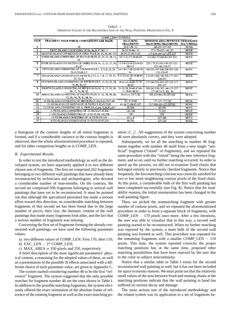
TABLE IOBSERVEDVALUES IN THE RECONSTRUCTION OF THEWALL -PAINTING PRESENTED INFIG. 8
a histogram of the contour lengths of all initial fragments isformed, and if a considerable variance in the contour lengths isobserved, then the whole aforementioned procedure is repeated,and for other comparison lengths so is COMP_LEN.
B. Experimental Results
In order to test the introduced methodology as well as the de-veloped system, we have separately applied it to two differentchosen sets of fragments. The first set comprised 262 fragmentsbelonging to two different wall paintings that have already beenreconstructed by technicians and archaeologists, who devoteda considerable number of man-months. On the contrary, thesecond set comprised 936 fragments belonging to several wallpaintings that have yet to be reconstructed. It must be pointedout that although the specialized personnel has made a seriouseffort toward this direction, no considerable matching betweenfragments of this second set has been found due to the largenumber of pieces, their size, the thematic content of the wallpaintings that made many fragments look alike, and the fact thata serious number of fragments was missing.
Concerning the first set of fragments forming the already con-structed wall paintings, we have used the following parametervalues:
a) two different values of COMP_LEN: First 170, then 110;b) EXC_LEN 2* COMP_LEN;c) MAX_AREA 350 pixels and 250, respectively.A brief description of the most significant parameters’ phys-
ical content, a reasoning for the adopted values of them, as wellas a presentation of the possible ill effects associated with a dif-ferent choice of each parameter value, are given in Appendix C.
The system started considering number 46 to be the first “ref-erence” fragment. The system suggested that the only possiblematches for fragment number 46 are the ones shown in Table I.In addition to the possible matching fragments, the system obvi-ously offered the exact orientation of the absolute frame of ref-erence of the rotating fragment as well as the exact matching po-
sition . All suggestions of the system concerning number46 were absolutely correct, and they were adopted.
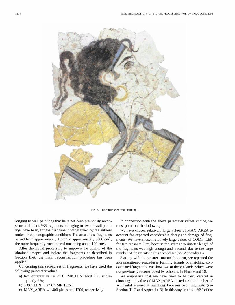
Subsequently, we let all the matching to number 46 frag-ments together with number 46 itself form a new single “arti-ficial” fragment (“island” of fragments), and we repeated thesame procedure with this “island” being the new reference frag-ment, and so on, until no further matching occurred. In order tospeed up the process, we did not re-examine fixed chains thatbelonged entirely to previously checked fragments. Notice thatfrequently, the first matching criterion was correctly satisfied fortwo or few more neighboring contour pixels of the fixed chain.At this point, a considerable bulk of the first wall painting hasbeen completed successfully (see Fig. 8). Notice that for read-ability reasons, the initial enumeration has been changed in thewall-painting figure.
Then, we picked the nonmatching fragment with greaternumber of contour pixels, and we repeated the aforementionedprocedure in order to form a separate block of fragments, withCOMP_LEN 170 pixels once more. After a few iterations,the user was able to visualize that in this way, a second wallpainting started to be reconstructed. When no further matchingwas reported by the system, a main bulk of the second wallpainting was formed as well. This procedure was repeated forthe remaining fragments with a smaller COMP_LEN110pixels. This time, the system reported correctly the propermatching positions but, at the same time, proposed othermatching possibilities that have been rejected by the user dueto the color or subject noncontinuity.
Notice that a similar table to Table I exists for the secondreconstructed wall painting as well, but it has not been includedfor space economy reasons. We must point out that the relativelysmall values of the area between fixed and rotating chains at thematching positions indicate that the wall painting in hand hassuffered no serious decay and damage.
The most serious test of the introduced methodology andthe related system was its application to a set of fragments be-
1284 IEEE TRANSACTIONS ON SIGNAL PROCESSING, VOL. 50, NO. 6, JUNE 2002
Fig. 8. Reconstructed wall painting.
longing to wall paintings that have not been previously recon-structed. In fact, 936 fragments belonging to several wall paint-ings have been, for the first time, photographed by the authorsunder strict photographic conditions. The area of the fragmentsvaried from approximately 1 cmto approximately 3000 cm,the more frequently encountered one being about 100 cm.
After the initial processing to improve the quality of theobtained images and isolate the fragments as described inSection II-A, the main reconstruction procedure has beenapplied.
Concerning this second set of fragments, we have used thefollowing parameter values:
a) two different values of COMP_LEN: First 300, subse-quently 250;
b) EXC_LEN 2* COMP_LEN;c) MAX_AREA 1400 pixels and 1200, respectively.
In connection with the above parameter values choice, wemust point out the following.
We have chosen relatively large values of MAX_AREA toaccount for expected considerable decay and damage of frag-ments. We have chosen relatively large values of COMP_LENfor two reasons: First, because the average perimeter length ofthe fragments was high enough and, second, due to the largenumber of fragments in this second set (see Appendix B).
Starting with the greater contour fragment, we repeated theaforementioned procedures forming islands of matching con-catenated fragments. We show two of these islands, which werenot previously reconstructed by scholars, in Figs. 9 and 10.
We emphasize that we have tried to be very careful inchoosing the value of MAX_AREA to reduce the number ofaccidental erroneous matching between two fragments (seeSection III-C and Appendix B). In this way, in about 60% of the
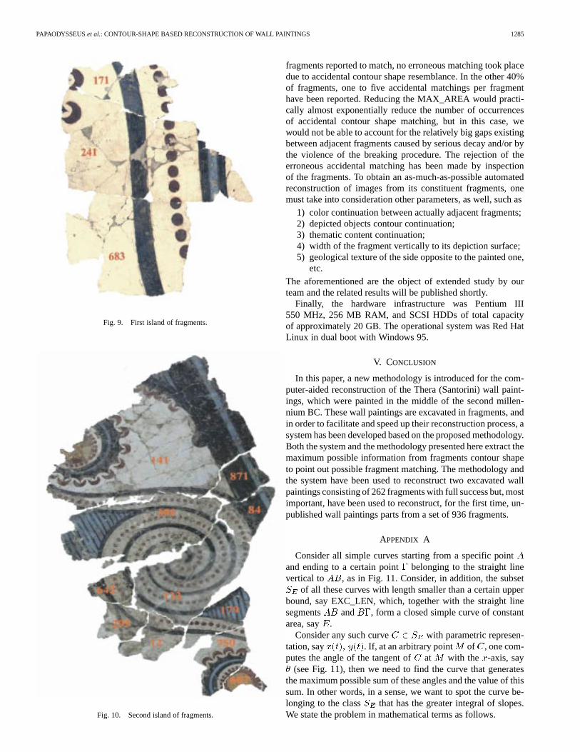
PAPAODYSSEUSet al.: CONTOUR-SHAPE BASED RECONSTRUCTION OF WALL PAINTINGS 1285
Fig. 9. First island of fragments.
Fig. 10. Second island of fragments.
fragments reported to match, no erroneous matching took placedue to accidental contour shape resemblance. In the other 40%of fragments, one to five accidental matchings per fragmenthave been reported. Reducing the MAX_AREA would practi-cally almost exponentially reduce the number of occurrencesof accidental contour shape matching, but in this case, wewould not be able to account for the relatively big gaps existingbetween adjacent fragments caused by serious decay and/or bythe violence of the breaking procedure. The rejection of theerroneous accidental matching has been made by inspectionof the fragments. To obtain an as-much-as-possible automatedreconstruction of images from its constituent fragments, onemust take into consideration other parameters, as well, such as
1) color continuation between actually adjacent fragments;2) depicted objects contour continuation;3) thematic content continuation;4) width of the fragment vertically to its depiction surface;5) geological texture of the side opposite to the painted one,
etc.The aforementioned are the object of extended study by ourteam and the related results will be published shortly.
Finally, the hardware infrastructure was Pentium III550 MHz, 256 MB RAM, and SCSI HDDs of total capacityof approximately 20 GB. The operational system was Red HatLinux in dual boot with Windows 95.
V. CONCLUSION
In this paper, a new methodology is introduced for the com-puter-aided reconstruction of the Thera (Santorini) wall paint-ings, which were painted in the middle of the second millen-nium BC. These wall paintings are excavated in fragments, andin order to facilitate and speed up their reconstruction process, asystem has been developed based on the proposed methodology.Both the system and the methodology presented here extract themaximum possible information from fragments contour shapeto point out possible fragment matching. The methodology andthe system have been used to reconstruct two excavated wallpaintings consisting of 262 fragments with full success but, mostimportant, have been used to reconstruct, for the first time, un-published wall paintings parts from a set of 936 fragments.
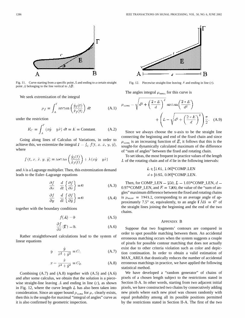
APPENDIX A
Consider all simple curves starting from a specific pointand ending to a certain point belonging to the straight linevertical to , as in Fig. 11. Consider, in addition, the subset
of all these curves with length smaller than a certain upperbound, say EXC_LEN, which, together with the straight linesegments and , form a closed simple curve of constantarea, say .
Consider any such curve with parametric represen-tation, say . If, at an arbitrary point of , one com-putes the angle of the tangent ofat with the -axis, say
(see Fig. 11), then we need to find the curve that generatesthe maximum possible sum of these angles and the value of thissum. In other words, in a sense, we want to spot the curve be-longing to the class that has the greater integral of slopes.We state the problem in mathematical terms as follows.
1286 IEEE TRANSACTIONS ON SIGNAL PROCESSING, VOL. 50, NO. 6, JUNE 2002
Fig. 11. Curve starting from a specific pointA and ending to a certain straightpointA belonging to the line vertical toAB.
We seek extremization of the integral
(A.1)
under the restriction
Constant (A.2)
Going along lines of Calculus of Variations, in order toachieve this, we extremize the integral ,where
and is a Lagrange multiplier. Then, this extremization demandleads to the Euler–Lagrange equations
(A.3)
(A.4)
together with the boundary conditions
(A.5)
(A.6)
Rather straightforward calculations lead to the system oflinear equations
(A.7)
(A.8)
Combining (A.7) and (A.8) together with (A.5) and (A.6)and after some calculus, we obtain that the solution is a piece-wise straight-line leaving and ending in line (), as shownin Fig. 12, where the curve length has also been taken intoconsideration. Since an upper bound for clearly exists,then this is the sought-for maximal “integral of angles” curve asit is also confirmed by geometric inspection.
Fig. 12. Piecewise straight-line leavingA and ending in line (").
The angles integral for this curve is
(A.9)
Since we always choose the x-axis to be the straight lineconnecting the beginning and end of the fixed chain and since
is an increasing function of , it follows that this is thesought-for dynamically calculated maximum of the differenceof “sum of angles” between the fixed and rotating chain.
To set ideas, the most frequent in practice values of the lengthof the rotating chain and of lie in the following intervals:
*COMP LEN
*COMP LEN
Then, for COMP_LEN , 1.03*COMP_LEN,0.97*COMP_LEN, and , the value of the “sum of an-gles” maximum difference between the fixed and rotating chainsis , corresponding to an average angle of ap-proximately 7.5 or, equivalently, to an angle ofthe straight lines joining the beginning and the end of the twochains.
APPENDIX B
Suppose that two fragments’ contours are compared inorder to spot possible matching between them. An accidentalerroneous matching occurs when the system suggests a coupleof pixels for possible contour matching that does not actuallyexist due to other criteria violation such as color and depic-tion continuation. In order to obtain a valid estimation ofMAX_AREA that drastically reduces the number of accidentalerroneous matchings in practice, we have applied the followingstatistical method.
We have developed a “random generator” of chains ofpixels of a chosen length subject to the restrictions stated inSection II-A. In other words, starting from two adjacent initialpixels, we have constructed two chains by consecutively addingnew pixels where each new pixel was chosen randomly withequal probability among all its possible positions permittedby the restrictions stated in Section II-A. The first of the two
PAPAODYSSEUSet al.: CONTOUR-SHAPE BASED RECONSTRUCTION OF WALL PAINTINGS 1287
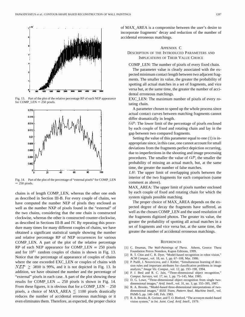
Fig. 13. Part of the plot of the relative percentage RP of each NEP appearancefor COMP_LEN= 250 pixels.
Fig. 14. Part of the plot of the percentage of “external pixels” for COMP_LEN= 250 pixels.
chains is of length COMP_LEN, whereas the other one endsas described in Section III-B. For every couple of chains, wehave computed the number NEP of pixels they enclosed aswell as the number NXP of pixels found in the “external” ofthe two chains, considering that the one chain is constructedclockwise, whereas the other is constructed counter-clockwise,as described in Sections III-B and IV. By repeating this proce-dure many times for many different couples of chains, we haveobtained a significant statistical sample showing the numberand relative percentage RP of NEP occurrences for variousCOMP_LEN. A part of the plot of the relative percentageRP of each NEP appearance for COMP_LEN250 pixelsand for 10 random couples of chains is shown in Fig. 13.Notice that the percentage of appearance of couples of chainswhere the one exceeded EXC_LEN or couples of chains with
is 99%, and it is not depicted in Fig. 13. Inaddition, we have obtained the number and the percentage of“external” pixels in each case. A part of the plot showing theseresults for COMP_LEN 250 pixels is shown in Fig. 14.From these figures, it is obvious that for a COMP_LEN250pixels, a choice of MAX_AREA 1100 pixels drasticallyreduces the number of accidental erroneous matchings or iteven eliminates them. Therefore, as expected, the proper choice
of MAX_AREA is a compromise between the user’s desire toincorporate fragments’ decay and reduction of the number ofaccidental erroneous matchings.
APPENDIX CDESCRIPTION OF THEINTRODUCED PARAMETERS AND
IMPLICATIONS OF THEIR VALUE CHOICE
COMP_LEN: The number of pixels of every fixed chain.The parameter value is clearly associated with the ex-
pected minimum contact length between two adjacent frag-ments. The smaller its value, the greater the probability ofspotting all actual matches in a set of fragments, and viceversa but, at the same time, the greater the number of acci-dental erroneous matchings.EXC_LEN: The maximum number of pixels of every ro-tating chain.
A parameter chosen to speed up the whole process sinceactual contact curves between matching fragments cannotdiffer dramatically in length.
: The lower limit of the percentage of pixels enclosedby each couple of fixed and rotating chain and lay in thegap between two compared fragments.
Setting the value of this parameter equal to one (1) is in-appropriate since, in this case, one cannot account for smalldeviations from the fragments perfect depiction occurring,due to imperfections in the shooting and image processingprocedures. The smaller the value of , the smaller theprobability of missing an actual match, but, at the sametime, the greater the number of false matches.
: The upper limit of overlapping pixels between theinterior of the two fragments for each comparison (samecomment as above).MAX_AREA: The upper limit of pixels number enclosedby each couple of fixed and rotating chain for which thesystem signals possible matching.
The proper choice of MAX_AREA depends on the ex-pected degree of decay the fragments have suffered, aswell as the chosen COMP_LEN and the used resolution ofthe fragments digitized photos. The greater its value, thegreater the probability of spotting all actual matches in aset of fragments and vice versa but, at the same time, thegreater the number of accidental erroneous matchings.
REFERENCES
[1] C. Doumas,The Wall-Paintings of Thera. Athens, Greece: TheraFoundation Petros Nomikos, Kapon Editions, 1999.
[2] R. T. Chin and C. R. Dyer, “Model-based recognition in robot vision,”ACM Comput., vol. 18, no. 1, pp. 67–108, Mar. 1986.
[3] P. Pudil, J. Novovicova, and J. Kittler, “Simultaneous learning of deci-sion rules and important attributes for classification problems in imageanalysis,”Image Vis. Comput., vol. 12, pp. 193–198, 1994.
[4] P. J. Besl and R. C. Jain, “Three-dimensional object recognition,”Comput. Surveys, vol. 17, no. 1, pp. 75–145, Mar. 1985.
[5] D. G. Lowe, “Three-dimensional object recognition from single two-dimensional images,”Artif. Intell., vol. 31, no. 3, pp. 355–395, 1987.
[6] R. A. Brooks, “Model-based three-dimensional interpretations of two-dimensional images,”IEEE Trans. Pattern Anal. Machine Intell., vol.PAMI-5, pp. 140–149, Feb. 1983.
[7] R. A. Brooks, R. Greiner, and T. O. Binford, “The acronym model-basedvision system,” inInt. Joint. Conf. Artif. Intell., 1979.

1288 IEEE TRANSACTIONS ON SIGNAL PROCESSING, VOL. 50, NO. 6, JUNE 2002
[8] J. F. Canny, “A computational approach to edge detection,”IEEE Trans.Pattern Anal. Machine Intell., vol. PAMI-8, pp. 679–698, Nov. 1986.
[9] T. F. Knoll and R. C. Jain, “Recognizing partially visible objects usingfeature indexed hypotheses,”IEEE J. Robot. Automat., vol. RA-2, pp.3–13, Mar. 1986.
[10] G. J. Ettinger, “Large hierarchical object recognition in robot vision,” inProc. Conf. Comput. Vision Pattern Recogn., 1988, pp. 32–41.
[11] W. E. L. Grimson, “Recognition of object families using parameterizedmodels,” inProc. First Int. Conf. Comput. Vision, 1987, pp. 93–101.
[12] Y. Lamdan, J. T. Schwartz, and H. J. Wolfson, “Object recognitionby affine invariant matching,” inProc. Conf. Comput. Vision PatternRecogn., 1988, pp. 335–344.
[13] C. Hansen and T. C. Henderson, “CAGD-based computer vision,”IEEETrans. Pattern Anal. Machine Intell., vol. 11, pp. 1181–1193, Nov. 1989.
[14] B. Bhanu and C. Ho, “CAD-based 3-d object recognition for robot vi-sion,” Comput., vol. 20, no. 8, pp. 19–36, 1987.
[15] L. G. Shapiro, “A CAD-model-based system for object localization,”Proc. SPIE, vol. 938, pp. 408–418, 1988.
[16] N. Narasimhamurti and R. C. Jain, “Computer-aided, design-basedobject recognition: Incorporating metric and topological information,”Proc. SPIE, vol. 938, pp. 436–443, 1988.
[17] J. J. Koenderink and A. J. van Doorn, “The singularities of the visualmapping,”Biol. Cybern., vol. 24, pp. 51–59, 1976.
[18] , “The internal representation of solid shape with respect to vision,”Biol. Cybern., vol. 32, pp. 211–216, 1979.
[19] I. Chakravarty and H. Freeman, “Characteristic views as a basis forthree-dimensional object recognition,”Proc. SPIE, vol. 336, pp. 37–45,1982.
[20] Z. Gigus and J. Malik, “Computing the aspect graph for line drawingsof polyhedral objects,”IEEE Trans. Pattern Anal. Machine Intell., vol.12, pp. 113–122, Feb. 1990.
[21] D. Eggert and K. Bowyer, “Computing the orthographic projection as-pect graph of solids of revolution,” inProc. IEEE Workshop Interpreta-tion 3-D Scenes, 1989, pp. 102–108.
[22] D. J. Kriegman and J. Ponce, “Computing exact aspect graphs of curvedobjects: Solids of revolution,” inProc IEEE Workshop Interpretation3-D Scenes, 1989, pp. 116–122.
[23] T. Sripradisvarakul and R. C. Jain, “Generating aspect graphs for curvedobjects,” inProc. IEEE Workshop Interpretation 3-D Scenes, 1989, pp.109–115.
[24] P. Arabie, L. J. Hubert, and G. De Soete, Eds.,Clustering and Classifi-cation. River Edge, NJ: World Scientific, 1996.
[25] R. Nevatia,Machine Perception. Englewood Cliffs, NJ: Prentice-Hall,1982.
[26] D. Marr and E. C. Hildreth, “Theory of edge detection,” inProc. R. Soc.Lond. B, vol. 207, 1980, pp. 187–217.
[27] R. Jain, R. Kasturi, and B. Schunck,Machine Vision. New York: Mc-Graw-Hill, 1995.
[28] K. Hirota and Y. Ohto, “Image recognition in jigsaw puzzle assemblyrobot systems,” Bull. Coll. Eng., Hosei Univ., Japan, May 1986.
[29] G. C. Burdea and H. J. Wolfson, “Solving jigsaw puzzles by a robot,”IEEE Trans. Robot. Automat., vol. 5, pp. 752–764, Dec. 1989.
[30] D. A. Kosiba, P. M. Devaux, S. Balasubramanian, T. L. Gandhi, andR. Kasturi, “An automatic jigsaw puzzle solver,” inProc. IEEE Conf.,1994.
[31] R. W. Webster, P. S. LaFollette, and R. L. Stafford, “Isthmus criticalpoints for solving jigsaw puzzles in computer vision,”IEEE Trans. Syst.,Man, Cybern., vol. 21, pp. 1271–1278, Sept./Oct. 1991.
[32] R. W. Webster and P. W. Ross, “A computer vision system that assemblescanonical jigsaw puzzles using the Euclidean skeleton and isthmus crit-ical points,” inProc. IAPR Workshop Machine Vision Applicat., Tokyo,Japan, Nov. 1990, pp. 28–30.
[33] G. Radack and N. Badler, “Jigsaw puzzle matching using a boundarycentered polar encoding,”Comput. Graph. Image Process., vol. 19, pp.1–2, May 1982.
[34] H. Freeman and L. Garder, “A pictorial jigsaw puzzle: The computersolution to a problem in pattern recognition,”IEEE Trans. Electron.Comput., vol. EC-13, pp. 118–127, Apr. 1964.
[35] K. Nagura, K. Sato, H. Mackawa, T. Morita, and K. Fujii, “Partial con-tour processing using curvature function—Assembly of jigsaw puzzleand recognition of moving figures,”Syst. Comput., vol. 2, pp. 30–39,Feb. 1986.
[36] P. J. Olver, G. Sapiro, and A. Tannenbaum, “Invariant geometric evolu-tions of surfaces and volumetric smoothing,”SIAM J. Appl. Math., vol.57, pp. 176–194, 1997.
[37] P. J. Olver, “Joint invariant signatures,”Found. Comput. Math., vol. 1,pp. 3–67, 2001.
[38] A. Zisserman, D. Forsyth, J. L. Mundy, C. Rothwell, J. Liu, and N.Pillow, “3D object recognition using invariance,”Artif. Intell., vol. 78,no. 1–2, pp. 239–288, 1995.
[39] P. J. Olver, G. Sapiro, and A. Tannenbaum, “Affine invariant detec-tion: Edge maps, anisotropic diffusion, and active contours,”Acta Appl.Math., vol. 59, pp. 45–77, 1999.
Constantin Papaodysseuswas born in Athens, Greece. He received theDiploma in electrical and computer engineering from National TechnicalUniversity of Athens (NTUA), the M.Sc. degree from Manchester University,Manchester, U.K., and the Ph.D. degree in computer engineering from NTUA.
He is an Associate Professor with the Department of Electrical and ComputerEngineering, NTUA. His research interests include music and speech processingand automatic recognition, image processing, applied mathematics, algorithmrobustness and quantization error analysis, adaptive algorithms, and biomed-ical engineering. He has more than 25 publications in international journals andmany publications in international conferences on these subjects.
Thanasis Panagopouloswas born in Athens, Greece, in 1973. He received theDiploma and M.Sc. degrees in electrical and computer engineering from theNational Technical University of Athens (NTUA) in 1996, where he is currentlypursuing the Ph.D. degree in computer engineering.
His research interests and recent work deal with music and speech processingand automatic recognition, image processing, pattern recognition, algorithmsfor echo cancellation, among other subjects. He has four publications in in-ternational journals and five publications in international conferences on thesesubjects.
Michael Exarhos was born in Athens, Greece, in 1973. He received theDiploma degree in electrical and computer engineering from DemokritusUniversity of Thrace, Thrace, Greece, in 1997. He is currently pursuing thePh.D. degree in computer engineering at the National Technical University ofAthens.
His research interests and recent work deal with image processing, musicprocessing, pattern recognition, bioengineering, VLSI, among other subjects.He has one publication in international journals and three publications in inter-national conferences on these subjects.
Constantin Triantafillou was born in Athens, Greece. He received the Diplomadegree in electrical and computer engineering from the National Technical Uni-versity of Athens (NTUA) in 1978, where he is currently a major informationcompany technical director and researcher.
His research interests and recent work deal with computer architecture andhardware, music processing, image processing, databases, pattern recognition,among other subjects. He has seven publications in international journals and12 publications in international conferences on these subjects.
Dimitrios Fragoulis was born in Athens, Greece, in 1973. He received theDiploma and M.Sc. degrees in electrical and computer engineering from Na-tional Technical University of Athens in 1996, where he is pursuing the Ph.D.degree in computer engineering.
His research interests and recent work deal with music and speech processingand automatic recognition, study of psychological and perceptual aspects ofsound, among other subjects. He has five publications in international journalsand eight publications in international conferences on these subjects.
Christos Doumas received the bachelors degree in history and archaeologyfrom the National University of Athens (NTUA), Athens, Greece, and the Ph.D.degree in archaeology from the University of London, London, U.K.
He was a Full Professor of Prehistoric Archaeology at NTUA from 1980 until2000. He is currently Director of Akrotiri Excavations, Thera, Greece. He hasnumerous publications in many international journals and is the author of sevenarchaeological books.


![VALUE€¦ · Contour Drawing [Project One] Contour Drawing. Contour Line: In drawing, is an outline sketch of an object. [Project One]: Layered Contour Drawing The purpose of contour](https://img.pdfslide.us/doc/110x75/60363a1e4c7d150c4824002e/value-contour-drawing-project-one-contour-drawing-contour-line-in-drawing-is.jpg)