Embed Size (px)
Citation preview
1/178 Siemens AP 01 · 2015
Continuous Gas Analyzers, extractiveCALOMAT 6
General information1
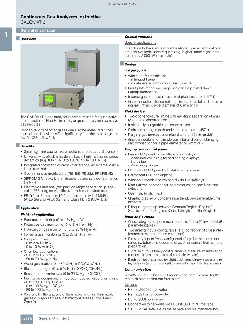
■ Overview
The CALOMAT 6 gas analyzer is primarily used for quantitative determination of H2or He in binary or quasi-binary non-corrosive gas mixtures.
Concentrations of other gases can also be measured if their thermal conductivities differ significantly from the residual gases like Ar, CO2, CH4, NH3.
■ Benefits
• Small T90 time due to micromechanical-produced Si sensor• Universally applicable hardware basis, high measuring range
dynamics (e.g. 0 to 1 %, 0 to 100 %, 95 to 100 % H2)• Integrated correction of cross-interference, no external calcu-
lation required• Open interface architecture (RS 485, RS 232, PROFIBUS)• SIPROM GA network for maintenance and service information
(option)• Electronics and analyzer part: gas-tight separation, purge-
able, IP65, long service life even in harsh environments• EEx(p) for Zones 1 and 2 (in accordance with 94/9/EC
(ATEX 2G and ATEX 3G), and Class I Div 2 (CSA) Ex(n)
■ Application
Fields of application• Pure gas monitoring (0 to 1 % H2 in Ar)• Protective gas monitoring (0 to 2 % He in N2)• Hydroargon gas monitoring (0 to 25 % H2 in Ar)• Forming gas monitoring (0 to 25 % H2 in N2)• Gas production:
- 0 to 2 % He in N2- 0 to 10 % Ar in O2
• Chemical applications: - 0 to 2 % H2 in NH3- 50 to 70 % H2 in N2
• Wood gasification (0 to 30 % H2 in CO/CO2/CH4)• Blast furnace gas (0 to 5 % H2 in CO/CO2/CH4/N2)• Bessemer converter gas (0 to 20 % H2 in CO/CO2)• Monitoring equipment for hydrogen-cooled turbo-alternators:
- 0 to 100 % CO2/Ar in air- 0 to 100 % H2 in CO2/Ar- 80 to 100 % H2 in air
• Versions for the analysis of flammable and non-flammable gases or vapors for use in hazardous areas (Zone 1 and Zone 2)
Special versions
Special applications
In addition to the standard combinations, special applications are also available upon request (e.g. higher sample gas pres-sure up to 2 000 hPa absolute).
■ Design
19" rack unit• With 4 HU for installation
- in hinged frame- in cabinets with or without telescopic rails
• Front plate for service purposes can be pivoted down(laptop connection)
• Internal gas paths: stainless steel pipe (mat. no. 1.4571)• Gas connections for sample gas inlet and outlet and for purg-
ing gas: fittings, pipe diameter of 6 mm or ¼"
Field device• Two-door enclosure (IP65) with gas-tight separation of ana-
lyzer and electronics sections• Individually purgeable enclosure halves• Stainless steel gas path and stubs (mat. no. 1.4571)• Purging gas connections: pipe diameter 10 mm or 3/8"• Gas connections for sample gas inlet and outlet: clamping
ring connection for a pipe diameter of 6 mm or ¼"
Display and control panel• Large LCD panel for simultaneous display of:
- Measured value (digital and analog displays)- Status bar- Measuring ranges
• Contrast of LCD panel adjustable using menu• Permanent LED backlighting• Washable membrane keyboard with five softkeys• Menu-driven operation for parameterization, test functions,
adjustment• User help in plain text• Graphic display of concentration trend; programmable time
intervals• Bilingual operating software German/English, English/
Spanish, French/English, Spanish/English, Italian/English
Input and outputs• One analog output per medium (from 0, 2, 4 to 20 mA; NAMUR
parameterizable)• Two analog inputs configurable (e.g. correction of cross-inter-
ference or external pressure sensor)• Six binary inputs freely configurable (e.g. for measurement
range switchover, processing of external signals from sample preparation)
• Six relay outputs freely configurable (e.g. failure, maintenance request, limit alarm, external solenoid valves)
• Each can be expanded by eight additional binary inputs and re-lay outputs (e.g. for autocalibration with max. four test gases)
Communication
RS 485 present in basic unit (connection from the rear; for the rack unit also behind the front plate).
Options• RS 485/RS 232 converter• RS 485/Ethernet converter• RS 485/USB converter• Connection to networks via PROFIBUS DP/PA interface• SIPROM GA software as the service and maintenance tool
AP01_2015_en_Kap01.book Seite 178 Freitag, 22. Mai 2015 10:33 10
© Siemens AG 2015
1/179Siemens AP 01 · 2015
Continuous Gas Analyzers, extractiveCALOMAT 6
General information1
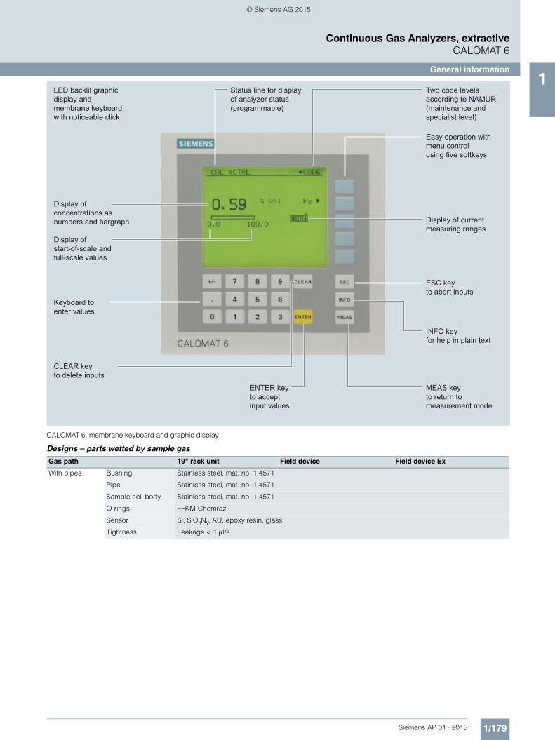
CALOMAT 6, membrane keyboard and graphic display
Designs – parts wetted by sample gas
Status line for display of analyzer status(programmable)
LED backlit graphicdisplay and membrane keyboardwith noticeable click
Two code levelsaccording to NAMUR(maintenance andspecialist level)
MEAS key to return tomeasurement mode
Easy operation with menu controlusing five softkeys
Display of currentmeasuring ranges
ESC keyto abort inputs
INFO keyfor help in plain text
CLEAR key to delete inputs
Keyboard toenter values
Display of start-of-scale and full-scale values
Display ofconcentrations asnumbers and bargraph
ENTER key to accept input values
Gas path 19" rack unit Field device Field device Ex
With pipes Bushing Stainless steel, mat. no. 1.4571
Pipe Stainless steel, mat. no. 1.4571
Sample cell body Stainless steel, mat. no. 1.4571
O-rings FFKM-Chemraz
Sensor Si, SiOxNy, AU, epoxy resin, glass
Tightness Leakage < 1 μl/s
AP01_2015_en_Kap01.book Seite 179 Freitag, 22. Mai 2015 10:33 10
© Siemens AG 2015

1/180 Siemens AP 01 · 2015
Continuous Gas Analyzers, extractiveCALOMAT 6
General information1
CALOMAT 6, 19" rack unit, gas path
CALOMAT 6, field device, gas path
AP01_2015_en_Kap01.book Seite 180 Freitag, 22. Mai 2015 10:33 10
© Siemens AG 2015

1/181Siemens AP 01 · 2015
Continuous Gas Analyzers, extractiveCALOMAT 6
General information1
■ Function
Principle of operation
The measuring principle is based on the different thermal con-ductivity of gases.
The CALOMAT 6 works with a micromechanically produced Si chip whose measuring membrane is equipped with thin-film resistors.
The resistors are kept at a constant temperature. This requires an current intensity depending on the thermal conductivity of the sample gas. This "raw value" is processed further electronically to calculate the gas concentration.
The sensor is located in a thermostatically-controlled stainless steel enclosure in order to prevent the influence of changes in ambient temperature.
To prevent the influence of changes in flow, the sensor is posi-tioned in a bore located to the side of the main flow.
Note
The sample gases must be fed into the analyzers free of dust. Condensation (dew point sample gas < ambient temperature) is to be avoided in the measurement chambers. Therefore, the use of gas modified for the measuring tasks is necessary in most ap-plication cases.
CALOMAT, principle of operation
Essential characteristics• Four freely parameterizable measuring ranges, also with sup-
pressed zero point, all measuring ranges linear• Smallest measuring spans up to 1 % H2 (with disabled zero
point: 95 to 100 % H2) possible• Measuring range identification• Galvanically isolated measured-value output 0/2/4 to 20 mA
(also inverted)• Autoranging or manual measurement range switchover possi-
ble; remote switching is also possible• Storage of measured values possible during adjustments• Wide range of selectable time constants (static/dynamic noise
suppression); i.e. the response time of the analyzer can be matched to the respective measuring task
• Short response time• Low long-term drift• Measuring point switchover for up to 6 measuring points
(programmable)• Measuring range identification• Measuring point identification• External pressure sensor can be connected – for the correc-
tion of sample gas fluctuations• Automatic range calibration can be parameterized• Operation based on the NAMUR recommendation
• Two control levels with their own authorization codes for the prevention of accidental and unauthorized operator interven-tions
• Simple handling using a numerical membrane keyboard and operator prompting
• Customer-specific analyzer options such as: - Customer acceptance- TAG labels- Drift recording- Clean for O2 service
Measuring spans
The smallest and largest possible spans depend on both the measured component (type of gas) and the respective applica-tion.
The smallest possible spans listed below refer to N2 as the resid-ual gas. With other gases which have a larger/smaller thermal conductivity than N2, the smallest possible span is also larger/smaller.
Influence of interfering gases
Knowledge of the sample gas composition is necessary to de-termine the influence of residual gases with several interfering components.
The following table lists the zero offsets expressed in % H2 re-sulting from 10 % residual gas (interfering gas) in each case.
For residual gas concentrations differing from 10 %, the corre-sponding multiple of the associated value in the table provides an acceptable approximation. This is valid for for residual gas concentrations up to 25 % (dependent on type of gas).
The thermal conductivity of most gas mixtures has a non-linear response. Even ambiguous results, such as e.g. with NH3/N2 mixtures, can occur within a specific concentration range.
Sample gas
Measuringmembrane with thin-film resistors
Component Smallest possible span
H2 0 ... 1 % (95 ... 100 %)
He 0 ... 2 %
Ar 0 ... 10 %
CO2 0 ... 20 %
CH4 0 ... 15 %
H2 in blast furnace gas 0 ... 10 %
H2 in converter gas 0 ... 20 %
H2 with wood gasification 0 ... 30 %
Component Zero offset
Ar -1.28 %
CH4 +1.59 %
C2H6 (non-linear response) +0.04 %
C3H8 -0.80 %
CO -0.11 %
CO2 -1.07 %
He +6.51 %
H2O (non-linear response) +1.58 %
NH3 (non-linear response) +1.3 %
O2 +0.18 %
SF6 -2.47 %
SO2 -1.34 %
100 % air (dry) +0.27 %
AP01_2015_en_Kap01.book Seite 181 Freitag, 22. Mai 2015 10:33 10
© Siemens AG 2015

1/182 Siemens AP 01 · 2015
Continuous Gas Analyzers, extractiveCALOMAT 6
General information1 In addition to a zero offset, it should also be noted that the gra-
dient of the characteristic is influenced by the residual gas. How-ever, this effect is negligible for most gases.
In case of correction of the influence of interfering gases with ad-ditional analyzers (ULTRAMAT 6/ULTRAMAT 23), the resulting measuring error can – depending on the application – amount up to 5 % of the smallest measuring range of the respective ap-plication.
Example of correction of cross-interference
Specification for the interface cable
Bus terminating resistors
Pins 3-7 and 8-9 of the first and last connectors of a bus cable must be bridged (see image).
Note
It is advisable to install a repeater on the device side in the case of a cable length of more than 500 m or with high interferences.
Up to four components can be corrected via the ELAN bus, cor-rection of cross-interference can be carried out for one or two components via the analog input.
Bus cable with plug connections, example
Surge impedance 100 ... 300 Ω, with a measuring frequency of > 100 kHz
Cable capacitance Typ. < 60 pF/m
Core cross-section > 0.22 mm2, corresponds to AWG 23
Cable type Twisted pair, 1 x 2 conductors of cable section
Signal attenuation Max. 9 dB over the whole length
Shielding Copper braided shield or braided shield and foil shield
Connection Pin 3 and pin 8
9-pin connector (RS 485)(device 3)
9-pin connector (RS 485)(device 2)
9-pin connector (RS 485)(device 1)
AP01_2015_en_Kap01.book Seite 182 Freitag, 22. Mai 2015 10:33 10
© Siemens AG 2015

1/183Siemens AP 01 · 2015
Continuous Gas Analyzers, extractiveCALOMAT 6
19" rack unit1
■ Technical specifications
General (based on EN 61207/IEC 1207. All data refers to the binary mixture H2 in N2)
Measuring ranges 4, internally and externally switch-able; automatic measurement range switchover also possible
Largest possible measuring span 100 vol.% H2 (for smallest mea-suring span, see "Function")
Measuring ranges with suppressed zero point
Any zero point within 0 ... 100 vol.% can be implemented, smallest possible measuring span: 5 % H2
Operating position Front wall, vertical
Conformity CE mark in accordance with EN 61326/A1 and EN 61010/1
Design, enclosure
Degree of protection IP20 according to EN 60529
Weight Approx. 10 kg
Electrical characteristics
EMC (Electromagnetic Compatibility) (All signal lines must be shielded. Measured value deviations of up to 4 % of the smallest measuring range may occur in ranges with strong electromagnetic interfer-ence.)
In accordance with standard requirements of NAMUR NE21 (08/98)
Electrical safety In accordance with EN 61010-1; overvoltage category II
Power supply (see rating plate) 100 V -10 % ... 120 V +10 % AC, 48 ... 63 Hz or 200 V -10 % ... 240 V +10 % AC, 48 ... 63 Hz
Power consumption Approx. 20 VA
Fuse values 100 ... 120 V: 1.0T/250200 ... 240 V: 0.63 T/250
Gas inlet conditions
Sample gas pressure 800 ... 1 100 hPa (absolute)
Sample gas flow 30 ... 90 l/h (0.5 ... 1.5 l/min)
Sample gas temperature Min. 0 to max. 50 °C, but above the dew point
Temperature of the measuring cell Approx. 60 ºC
Sample gas humidity < 90 % relative humidity
Dynamic response
Warm-up period < 30 min (the technical specifica-tion will be met after 2 hours)
Delayed display (T90) < 5 s
Damping (electrical time constant) 0 ... 100 s, parameterizable
Dead time (purging time of the gas path in the unit at 1 l/min)
Approx. 0.5 s
Measuring response (relating to sample gas pressure 1 013 hPa absolute, 0.5 l/min sample gas flow and 25 °C ambient temperature)
Output signal fluctuation < ± 0.75 % of the smallest possi-ble measuring range according to rating plate, with electronic damping constant of 1 s (σ = 0.25 %)
Zero point drift < ± 1 %/week of the smallest pos-sible measuring span according to rating plate
Measured-value drift < ± 1 %/week of the smallest pos-sible measuring span according to rating plate
Repeatability < 1 % of the current measuring range
Detection limit 1 % of the current measuring range
Linearity error < ± 1 % of the current measuring range
Influencing variable (relating to sample gas pressure 1 013 hPa absolute, 0.5 l/min sample gas flow and 25 °C ambient temperature)
Ambient temperature < 1 %/10 K referred to smallest possible measuring span accord-ing to rating plate
Carrier gases Deviation from zero point (for influence of interfering gas see paragraph titled "Interference influences")
Sample gas flow < 0.2 % of the smallest possible span according to rating plate with a change in flow of 0.1 l/min within the permissible flow range
Sample gas pressure < 1 % of the current measuring range with a pressure change of 100 hPa
Power supply < 0.1 % of the current measuring range with rated voltage ± 10 %
Electrical inputs and outputs
Analog output 0/2/4 ... 20 mA, isolated; load max. 750 Ω
Relay outputs 6, with changeover contacts, freely parameterizable, e.g. for measuring range identification; load: 24 V AC/DC/1 A, isolated
Analog inputs 2, dimensioned for 0/2/4 … 20 mA for external pres-sure sensor and correction of cross-interference
Binary inputs 6, designed for 24 V, isolated, freely parameterizable, e.g. for measurement range switchover
Serial interface RS 485
Options AUTOCAL function with 8 additional binary inputs and relay outputs each, also with PROFIBUS PA or PROFIBUS DP
Climatic conditions
Permissible ambient temperature -30 … +70 °C during storage and transportation, 5 … 45 °C during operation
Permissible humidity (dew point must not be undershot)
< 90 % relative humidity as annual average, during storage and transportation
AP01_2015_en_Kap01.book Seite 183 Freitag, 22. Mai 2015 10:33 10
© Siemens AG 2015

1/184 Siemens AP 01 · 2015
Continuous Gas Analyzers, extractiveCALOMAT 6
19" rack unit1
1) Ready to enter external correction of cross-interferences for CO, CO2 and CH4 (CH4 only for blast furnace gas and wood gasification).
Selection and ordering data Article No.
CALOMAT 6 gas analyzer19" rack unit for installation in cabinets
7MB2521- 777 0 00000 7 - 7A 7 7 Cannot be combined
Click on the Article No. for the online configuration in the PIA Life Cycle Portal.
Connections for sample gasPipe with 6 mm outer diameterPipe with 1/4" outer diameter
01
Measured component Smallest/largest measuring range
H2 in N2 0 ... 1/100 % A AH2 in N2 (blast furnace gas measurement)1) 0 ... 5/100 % AW
H2 in N2 (converter measurement)1) 0 ... 5/100 % A XH2 in N2 (wood gasification)1) 0 ... 5/100 % A Y
H2 in Ar 0 ... 1/100 % A BH2 in NH3 0 ... 1/100 % A C
He in N2 0 ... 2/100 % B AHe in Ar 0 ... 2/100 % B B
He in H2 0 ... 10/80 % B C
Ar in N2 0 ... 10/100 % C AAr in O2 0 ... 10/100 % C B
CO2 in N2 0 ... 20/100 % D A
CH4 in Ar 0 ... 15/100 % E A
NH3 in N2 0 ... 10/30 % F A
H2 monitoring (turbo generators) G A GA• CO2 in air 0 ... 100 %• H2 in CO2 0 ... 100 %• H2 in air 80 ... 100 %
Add-on electronicsWithout 0AUTOCAL function• With 8 additional digital inputs and outputs 1• With 8 additional digital inputs/outputs and PROFIBUS PA interface 6 6• With 8 additional digital inputs/outputs and PROFIBUS DP interface 7 7
Power supply100 ... 120 V AC, 48 ... 63 Hz 0200 ... 240 V AC, 48 ... 63 Hz 1
Explosion protectionWithout ACertificate: ATEX II 3G, flammable and non-flammable gases BFM/CSA certificate – Class I Div 2 D
Language (supplied documentation, software)German 0English 1French 2Spanish 3Italian 4
AP01_2015_en_Kap01.book Seite 184 Freitag, 22. Mai 2015 10:33 10
© Siemens AG 2015
1/185Siemens AP 01 · 2015
Continuous Gas Analyzers, extractiveCALOMAT 6
19" rack unit1
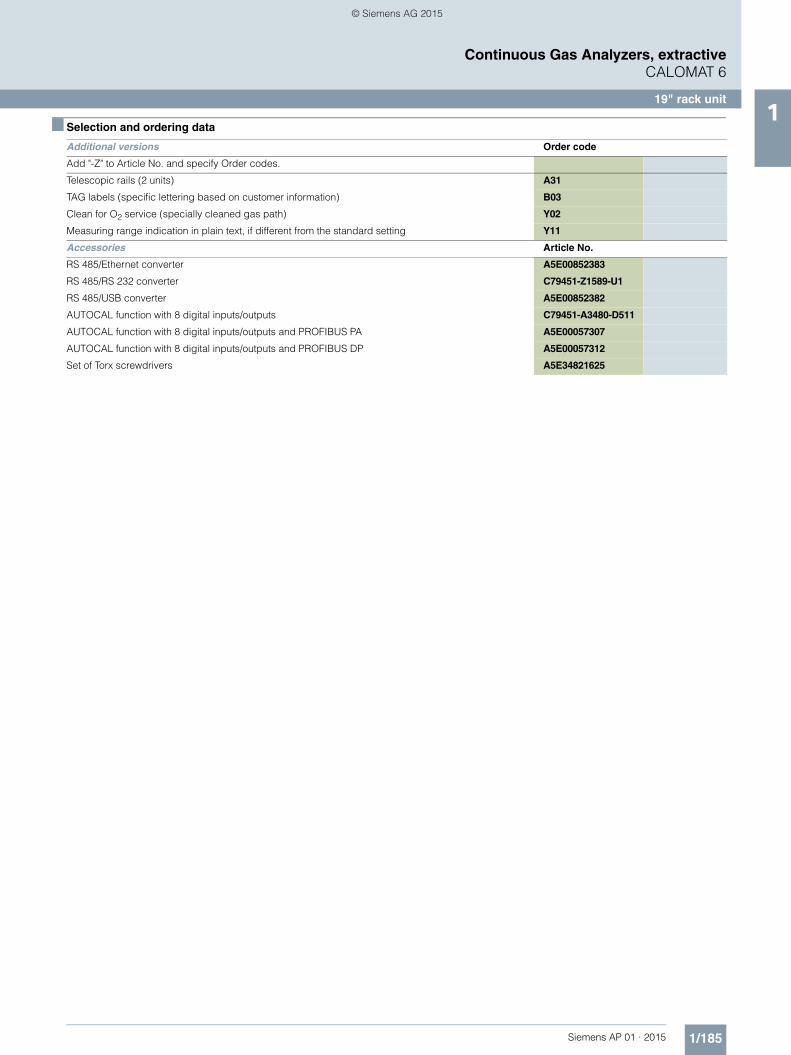
■ Selection and ordering data
Additional versions Order code
Add "-Z" to Article No. and specify Order codes.
Telescopic rails (2 units) A31
TAG labels (specific lettering based on customer information) B03
Clean for O2 service (specially cleaned gas path) Y02
Measuring range indication in plain text, if different from the standard setting Y11
Accessories Article No.
RS 485/Ethernet converter A5E00852383
RS 485/RS 232 converter C79451-Z1589-U1
RS 485/USB converter A5E00852382
AUTOCAL function with 8 digital inputs/outputs C79451-A3480-D511
AUTOCAL function with 8 digital inputs/outputs and PROFIBUS PA A5E00057307
AUTOCAL function with 8 digital inputs/outputs and PROFIBUS DP A5E00057312
Set of Torx screwdrivers A5E34821625
AP01_2015_en_Kap01.book Seite 185 Freitag, 22. Mai 2015 10:33 10
© Siemens AG 2015

1/186 Siemens AP 01 · 2015
Continuous Gas Analyzers, extractiveCALOMAT 6
19" rack unit1
■ Dimensional drawings
CALOMAT 6, 19“ unit, dimensions in mm
s
AP01_2015_en_Kap01.book Seite 186 Freitag, 22. Mai 2015 10:33 10
© Siemens AG 2015

1/187Siemens AP 01 · 2015
Continuous Gas Analyzers, extractiveCALOMAT 6
19" rack unit1
■ Schematics
Pin assignment (electrical and gas connections)
CALOMAT 6, 19“ unit, pin assignment
Ω
Ω
AP01_2015_en_Kap01.book Seite 187 Freitag, 22. Mai 2015 10:33 10
© Siemens AG 2015

1/188 Siemens AP 01 · 2015
Continuous Gas Analyzers, extractiveCALOMAT 6
19" rack unit1
CALOMAT 6, 19“ unit, pin assignment of AUTOCAL board and PROFIBUS connectors
AP01_2015_en_Kap01.book Seite 188 Freitag, 22. Mai 2015 10:33 10
© Siemens AG 2015

1/189Siemens AP 01 · 2015
Continuous Gas Analyzers, extractiveCALOMAT 6
19" rack unit1
CALOMAT 6, 19“ unit, gas and electrical connections
Gas connections: stubs 6 mm or ¼"
Power supplyand fuses
37-pin connectorBinary inputs andrelay outputs (option)
9-pininterfaceconnector(option): e.g.PROFIBUS
9-pinconnector:RS 485
15-pin connectorBinary inputs andanalog inputs/outputs
Sample gas inletPurging gas inlet
Sample gas outlet
25-pin connectorBinary inputs andrelay outputs
AP01_2015_en_Kap01.book Seite 189 Freitag, 22. Mai 2015 10:33 10
© Siemens AG 2015

1/190 Siemens AP 01 · 2015
Continuous Gas Analyzers, extractiveCALOMAT 6
Field device1
■ Technical specifications
General (based on DIN EN 61207 / IEC 1207. All data refers to the binary mixture H2 in N2)
Measuring ranges 4, internally and externally switch-able; automatic measuring range changeover also possible
Largest possible measuring span 100 vol.% H2 (for smallest mea-suring span, see "Function")
Measuring ranges with suppressed zero point
Any zero point within 0 ... 100 vol.% can be implemented; smallest possible measuring span: 5 % H2
Operating position Front wall, vertical
Conformity CE mark in accordance with EN 61326/A1 and EN 61010/1
Design, enclosure
Degree of protection IP65 according to EN 60529
Weight Approx. 25 kg
Electrical characteristics
EMC (Electromagnetic Compatibility) (All signal lines must be shielded. Measured value deviations of up to 4 % of the smallest measuring range may occur in ranges with strong electromagnetic interfer-ence.)
In accordance with standard requirements of NAMUR NE21 (08/98)
Electrical safety In accordance with EN 61010-1; overvoltage category II
Power supply (see rating plate) 100 V -10 % ... 120 V +10 % AC, 48 ... 63 Hz or 200 V -10 % ... 240 V +10 % AC, 48 ... 63 Hz
Power consumption (unit) Approx. 20 VA
Fuse values 100 ... 120 V: 1.0T/250200 ... 240 V: 0.63 T/250
Gas inlet conditions
Sample gas pressure 800 ... 1 100 hPa (absolute)
Sample gas flow 30 ... 90 l/h (0.5 ... 1.5 l/min)
Sample gas temperature Min. 0 to max. 50 °C, but above the dew point
Temperature of the measuring cell Approx. 60 ºC
Sample gas humidity < 90 % relative humidity
Purging gas pressure
• Permanent 165 hPa above ambient pressure
• For short periods Max. 250 hPa above ambient pressure
Dynamic response (relating to sample gas pressure 1 000 hPa absolute, 0.5 l/min sample gas flow and 25 °C ambient temperature)
Warm-up period < 30 min (the technical specifica-tion will be met after 2 hours)
Delayed display (T90) < 5 s
Electrical damping 0 ... 100 s, parameterizable
Dead time (at 1 l/min) Approx. 0.5 s
Measuring response (relating to sample gas pressure 1 013 hPa absolute, 0.5 l/min sample gas flow and 25 °C ambient temperature)
Output signal fluctuation (maximum accuracy achieved after 2 hours)
< ± 0.75 % of the smallest possi-ble measuring range according to rating plate, with electronic damping constant of 1 s (σ = 0.25 %)
Zero point drift < ± 1 %/week of the smallest pos-sible measuring span according to rating plate
Measured-value drift < ± 1 %/week of the smallest pos-sible measuring span according to rating plate
Repeatability < 1 % of the current measuring range
Detection limit 1 % of the current measuring range
Linearity error < ± 1 % of the current measuring range
Influencing variables (relating to sample gas pressure 1013 hPa absolute, 0.5 l/min sample gas flow and 25 °C ambient temperature)
Ambient temperature < 1 %/10 K referred to smallest possible measuring span accord-ing to rating plate
Carrier gases Deviation from zero point (for influence of interfering gas see paragraph titled "Interference influences")
Sample gas flow < 0.2 % of the smallest possible span according to rating plate with a change in flow of 0.1 l/min within the permissible flow range
Sample gas pressure < 1 % of the current measuring range with a pressure change of 100 hPa
Electrical inputs and outputs
Analog output 0/2/4 ... 20 mA, isolated; load max. 750 Ω
Relay outputs 6, with changeover contacts, freely parameterizable, e.g. for measuring range identification; load: 24 V AC/DC/1 A, isolated
Analog inputs 2, dimensioned for 0/2/4 ... 20 mA for external pressure sensor and correction of cross-interference
Binary inputs 6, designed for 24 V, isolated, freely parameterizable, e.g. for measurement range switchover
Serial interface RS 485
Options AUTOCAL function with 8 additional binary inputs and relay outputs each, also with PROFIBUS PA or PROFIBUS DP
Climatic conditions
Permissible ambient temperature -30 ... +70 °C during storage and transportation, 5 … 45 °C during operation
Permissible humidity (dew point must not be undershot)
< 90 % relative humidity as annual average, during storage and transportation
AP01_2015_en_Kap01.book Seite 190 Freitag, 22. Mai 2015 10:33 10
© Siemens AG 2015

1/191Siemens AP 01 · 2015
Continuous Gas Analyzers, extractiveCALOMAT 6
Field device1
1) Ready to enter external correction of cross-interferences for CO, CO2 and CH4 (CH4 only for blast furnace gas and wood gasification).2) Only in connection with an approved purging unit.
Selection and ordering data Article No.
CALOMAT 6 gas analyzerFor field installation
7MB2511- 777 0 00000 7 - 7A 7 7 Cannot be combined
Click on the Article No. for the online configuration in the PIA Life Cycle Portal.
Connections for sample gasFerrule screw connection for pipe, outer diameter 6 mmFerrule screw connection for pipe, outer diameter 1/4"
01
Measured component Smallest/largest measuring range
H2 in N2 0 ... 1/100 % A A A AH2 in N2 (blast furnace gas measurement)1) 0 ... 5/100 % AW AW
H2 in N2 (converter measurement)1) 0 ... 5/100 % A X A XH2 in N2 (wood gasification)1) 0 ... 5/100 % A Y A Y
H2 in Ar 0 ... 1/100 % A B A BH2 in NH3 0 ... 1/100 % A C A C
He in N2 0 ... 2/100 % B AHe in Ar 0 ... 2/100 % B BHe in H2 0 ... 10/80 % B C B C
Ar in N2 0 ... 10/100 % C AAr in O2 0 ... 10/100 % C B
CO2 in N2 0 ... 20/100 % D A
CH4 in Ar 0 ... 15/100 % E A E ANH3 in N2 0 ... 10/30 % F A F A
H2 monitoring (turbo generators) G A G A GA• CO2 in air 0 ... 100 %• H2 in CO2 0 ... 100 %• H2 in air 80 ... 100 %
Add-on electronicsWithout 0AUTOCAL function• With 8 additional digital inputs and outputs 1• With 8 additional digital inputs/outputs and PROFIBUS PA interface 6 6 6
• With 8 additional digital inputs/outputs and PROFIBUS DP interface 7 7 7• With 8 additional digital inputs/outputs and PROFIBUS PA Ex-i interface 8 8 8
Power supply100 ... 120 V AC, 48 ... 63 Hz 0200 ... 240 V AC, 48 ... 63 Hz 1
Explosion protection, incl. certificateWithout AAcc. to ATEX II 3G, non-flammable gases B BAcc. to ATEX II 3G; flammable gases2) CFM/CSA certificate – Class I Div 2 D DAccording to ATEX II 2G, leakage compensation2) E EAccording to ATEX II 2G, continuous purging2) F FATEX II 3D certificate; potentially explosive dust atmospheres• In non-hazardous gas zone G• In Ex zone acc. to ATEX II 3G, non-flammable gases H• In Ex zone acc. to ATEX II 3G, flammable gases2) J
Language (supplied documentation, software)German 0English 1French 2Spanish 3Italian 4
AP01_2015_en_Kap01.book Seite 191 Freitag, 22. Mai 2015 10:33 10
© Siemens AG 2015

1/192 Siemens AP 01 · 2015
Continuous Gas Analyzers, extractiveCALOMAT 6
Field device1
■ Selection and ordering data
Additional versions Order code
Add "-Z" to Article No. and specify Order codes.
TAG labels (specific lettering based on customer information) B03
BARTEC EEx p control unit "Leakage compensation" E71
BARTEC EEx p control unit "Continuous purging" E72
Clean for O2 service (specially cleaned gas path) Y02
Measuring range indication in plain text, if different from the standard setting Y11
Additional units for Ex versions Article No.
ATEX Category II 2G (zone 1)
BARTEC EEx p control unit, 230 V, "leakage compensation" 7MB8000-2BA
BARTEC EEx p control unit, 115 V, "leakage compensation" 7MB8000-2BB
BARTEC EEx p control unit, 230 V, "continuous purging" 7MB8000-2CA
BARTEC EEx p control unit, 115 V, "continuous purging" 7MB8000-2CB
Ex isolation amplifier 7MB8000-3AB
Ex isolating relay, 230 V 7MB8000-4AA
Ex isolating relay, 110 V 7MB8000-4AB
Differential pressure switch for corrosive and non-corrosive gases 7MB8000-5AA
Stainless steel flame arrestor 7MB8000-6BA
Hastelloy flame arrestor 7MB8000-6BB
ATEX Category II 3G (zone 2)
BARTEC EEx p control unit, 230 V, "continuous purging" 7MB8000-2CA
BARTEC EEx p control unit, 115 V, "continuous purging" 7MB8000-2CB
FM/CSA (Class I Div. 2)
Ex purging unit Minipurge FM 7MB8000-1AA
Accessories
RS 485/Ethernet converter A5E00852383
RS 485/RS 232 converter C79451-Z1589-U1
RS 485/USB converter A5E00852382
AUTOCAL function with 8 digital inputs/outputs A5E00064223
AUTOCAL function with 8 digital inputs/outputs and PROFIBUS PA A5E00057315
AUTOCAL function with 8 digital inputs/outputs and PROFIBUS DP A5E00057318
AUTOCAL function with 8 digital inputs/outputs and PROFIBUS PA Ex i (firmware 4.1.10 required) A5E00057317
Set of Torx screwdrivers A5E34821625
AP01_2015_en_Kap01.book Seite 192 Freitag, 22. Mai 2015 10:33 10
© Siemens AG 2015

1/193Siemens AP 01 · 2015
Continuous Gas Analyzers, extractiveCALOMAT 6
Field device1
■ Dimensional drawings
CALOMAT 6, field unit, dimensions in mm
s
AP01_2015_en_Kap01.book Seite 193 Freitag, 22. Mai 2015 10:33 10
© Siemens AG 2015

1/194 Siemens AP 01 · 2015
Continuous Gas Analyzers, extractiveCALOMAT 6
Field device1
■ Schematics
Pin assignment (electrical and gas connections)
CALOMAT 6, field unit, connector and terminal assignment
ΩΩ
AP01_2015_en_Kap01.book Seite 194 Freitag, 22. Mai 2015 10:33 10
© Siemens AG 2015
1/195Siemens AP 01 · 2015
Continuous Gas Analyzers, extractiveCALOMAT 6
Field device1
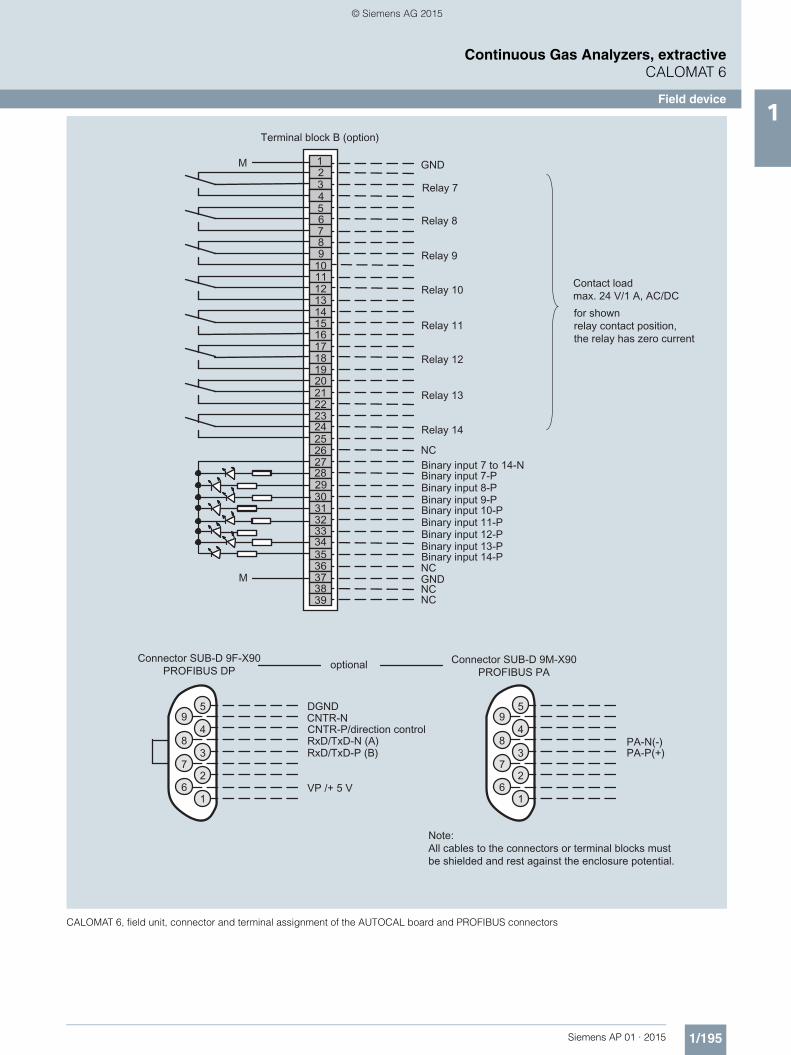
CALOMAT 6, field unit, connector and terminal assignment of the AUTOCAL board and PROFIBUS connectors
AP01_2015_en_Kap01.book Seite 195 Freitag, 22. Mai 2015 10:33 10
© Siemens AG 2015
1/196 Siemens AP 01 · 2015
Continuous Gas Analyzers, extractiveCALOMAT 6
Field device1
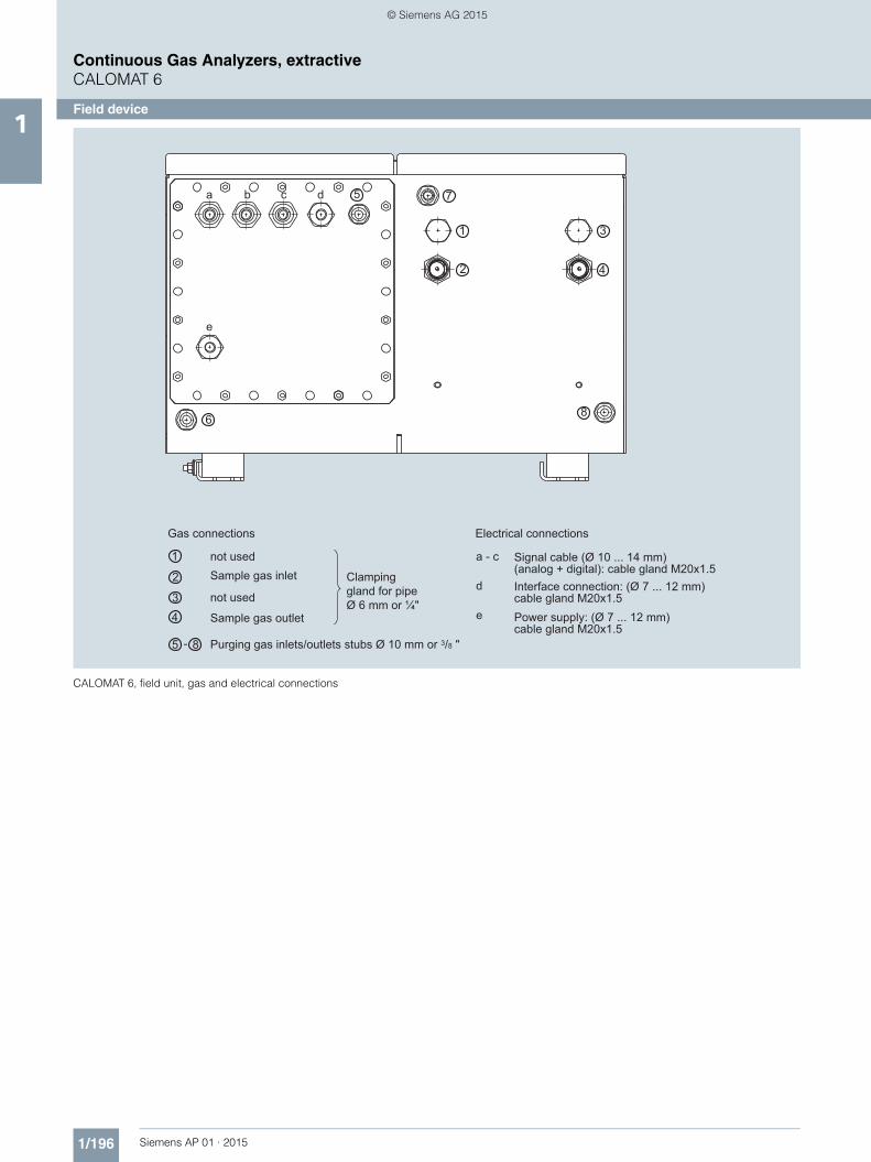
CALOMAT 6, field unit, gas and electrical connections
8
1
2
6
7a b c d
e
5
3
4
1
2
85
3
-
4
a - c
d
e
not usedSample gas inlet
not used
Sample gas outlet
Purging gas inlets/outlets stubs Ø 10 mm or 3/8 "
Clampinggland for pipeØ 6 mm or ¼"
Gas connections Electrical connections
Interface connection: (Ø 7 ... 12 mm)cable gland M20x1.5
Signal cable (Ø 10 ... 14 mm)(analog + digital): cable gland M20x1.5
Power supply: (Ø 7 ... 12 mm)cable gland M20x1.5
AP01_2015_en_Kap01.book Seite 196 Freitag, 22. Mai 2015 10:33 10
© Siemens AG 2015

1/197Siemens AP 01 · 2015
Continuous Gas Analyzers, extractiveCALOMAT 6
Documentation1
■ Selection and ordering data
■ Selection and ordering data
If the CALOMAT 6 is supplied with a specially cleaned gas path for high oxygen context ("Cleaned for O2 service"), please ensure that you specify this when ordering spare parts. This is the only way to guarantee that the gas path will continue to comply with the special requirements for this version.
Operating instructions Article No.
CALOMAT 6Thermal conductivity gas analyzer
• German A5E00116454
• English A5E00116455
• French A5E00116456
• Italian A5E00116457
• Spanish A5E00116458
Gas analyzers of Series 6 and ULTRAMAT 23
Schnittstelle/Interface PROFIBUS DP/PA
• German and English A5E00054148
Suggestions for spare parts
7MB2521 7MB2511 7MB2511 Ex 2 years (quantity)
5 years (quantity)
Article No.
Analyzer unit
Measuring cell x x x 1 1 A5E00095332
O ring (set of 4) x x x 1 2 A5E00124182
Electronics
Fuse (device fuse) x 1 2 A5E00061505
Front plate without LC display x 1 1 C79165-A3042-B508
Motherboard, with firmware: see spare parts list
x x x - 1
Adapter plate, LCD/keyboard x x 1 1 C79451-A3474-B605
LC display (non-Ex version) x 1 1 W75025-B5001-B1
Line transformer, 115 V x x x - 1 W75040-B21-D80
Line transformer, 230 V x x x - 1 W75040-B31-D80
Connector filter x x x - 1 W75041-E5602-K2
Fusible element, T 0.63/250 V x x 2 3 W79054-L1010-T630
Fusible element, 1 A, 110/120 V x x x 2 3 W79054-L1011-T100
AP01_2015_en_Kap01.book Seite 197 Freitag, 22. Mai 2015 10:33 10
© Siemens AG 2015