Embed Size (px)
Citation preview

Contextualized Learning Activities (CLAs) for the Specialist High Skills Majors
For their three “other”, non-major required credits, students in a Specialist High Skills Major program must complete learning activities that are contextualized to the knowledge and skills relevant to the economic sector of the SHSM. Contextualized learning activities (CLAs) address curriculum expectations in these courses. CLAs must take a minimum of 6 hours to complete. Boards may choose to develop one activity that takes 6 hours to complete or two or more activities that together take a minimum of 6 hours to complete. This template must be used to describe the CLAs. The completed form must be submitted to the Ministry of Education for approval. ______________________________________________________________________ Contextualized Learning Activity (CLA) Template Submit all material in Microsoft Word.
Contact Information Board Hamilton Wentworth District School Board
Development date
June 2008
Contact person
Gail Cipriani
Position
Special Assignment - SHSM Implementation
Phone
905-527-5092 x 2385
Fax
905-521-2531
Specialist High Skills Major
Manufacturing
Course code and course title
SPH4C, Physics Grade 12 College Preparation
Name of CLA
Simple Machines and Torque
Page 1 of 26

Brief description of CLA Students will apply the ideas of torque and mechanical advantage to a
manufacturing setting. Examples provided will connect theory from the classroom to practice in the shop.
Duration 6 hours
Overall expectations MSV.01 · describe and apply concepts related to forces, Newton’s laws of motion, static and kinetic friction, simple machines, torques, and mechanical advantage; MSV.02 · design and carry out experiments to investigate forces, coefficients of friction, and the operation of simple machines; MSV.03 · identify and analyse applications of applied forces, friction, and simple machines in real-world machines and in the human body.
Specific expectations MS1.07 – explain the operation and mechanical advantage of simple machines; MS1.08 – determine the mechanical advantage of a variety of compound machines and bio-mechanical systems. MS2.04 – analyse, in quantitative terms, a mechanical system with respect to its component simple machines, input and output forces, and mechanical advantage (e.g., determine the mechanical advantage of the simple machines in a bicycle); MS3.03 – analyse natural and technological systems that employ the principles of simple machines, and explain their function and structure (e.g., analyse the operation of the human arm in terms of the operation of a lever). SIS.02 - select appropriate instruments and testing equipment and use them effectively and accurately in collecting observations and data (e.g., troubleshoot electrical circuits using electrical tools and such measuring instruments as ammeters, voltmeters, and oscilloscopes); SIS.03 - demonstrate the skills required to design and carry out experiments related to the topics under study, controlling major variables and adapting or extending procedures where required (e.g., design and carry out an experiment to determine the relationships among force, area, pressure, volume, and time in a hydraulic system); SIS.05 - compile, organize, and interpret data, using appropriate formats and treatments, including tables, flow charts, graphs, and diagrams (e.g., explain the reflection and refraction of light in various situations, using ray diagrams); SIS.06 - use appropriate scientific models (theories, laws, explanatory devices) to explain and predict the behaviour of natural phenomena; SIS.07 - analyse and synthesize information for the purpose of identifying problems for inquiry, and solve the problems using a variety of problem-solving skills; SIS.08 - select and use appropriate SI units, and apply unit analysis techniques when solving problems; SIS.09 - select and use appropriate numeric, symbolic, graphical, and
Page 2 of 26

linguistic modes of representation (e.g., algebraic equations, vector diagrams, free-body diagrams, ray diagrams, graphs, graphing programs, spreadsheets) to communicate scientific ideas, plans, and experimental results;
Essential Skills and work habits
(List the Essential Skills and work habits that are addressed in the CLA(s).)
Catholic graduate expectations (if applicable)
See SPH4C Course Profile page for Ontario Catholic School Graduate Expectations
Teaching/Learning Strategies Teacher’s notes This contextualized unit has been designed for grade 12 college physics students enrolled in the Specialist High Skills Major Manufacturing program. Sections 1 to 6 introduce the ideas of torque and mechanical advantage with many opportunities for practice. Sections 7 and 8 allow the students to apply the concepts learned to manufacturing types of problems. It is recommended that the teacher review forces and Newton’s laws before beginning this unit. Students will need instruction or review, about how to use a Newton spring scale to measure forces. It would also be helpful to have the class think of every day things that can be used to visualize torque and levers, such as opening a door, prying a nail, using scissors, etc… For the final section, students may want to visit a manufacturing classroom. Safety awareness is required, prior to the student’s visits and supervision at all times while the students are in machine shop. Once completed all sections of this unit are to be submitted for teacher evaluation. All answer keys and a marking rubric has been provided in Appendix A. Context (Describe the workplace context for the activity/activities.) Strategies
- before beginning this unit review forces and Newton’s Laws - discuss the idea of torque (rotational force) with the class - have the students come up with examples of where torque is used in everyday items - have students talk about torque in general terms. For example if the force remains constant and
the distance between the applied force and the fulcrum gets smaller what happens to the torque, if the torque remains the same and the distance between the applied force and the fulcrum gets smaller what has to happen to the applied force, etc…
- have students begin handout and provide instruction to individuals as required. - students will benefit from seeing examples of simple machines in real life such as drill presses,
lathes, and other machining instruments that use levers, pulleys, or gears.
Page 3 of 26

Assessment and Evaluation of Student Achievement Tasks Type of assessment Section 1 and 2
Diagnostic X Formative □ Summative □
Section 3 to 6
Diagnostic □ Formative X Summative □
Section 7 and 8
Diagnostic □ Formative □ Summative X
Assessment tools See Appendix A
Additional Notes/Comments/Explanations (Provide additional suggestions for teachers that will help them deliver this CLA.)
Resources Course Profile Physics, Grade 12, College Preparation SPH4C http://www.curriculum.org/csc/library/profiles/12/html/SPH4CP.htm Authentic workplace materials None- all required material is self contained in this unit Human resources None required unless needed as per IEP suggested strategies. Print None- all required material is self contained in this unit Video None Software None Websites http://www.curriculum.org/csc/library/profiles/12/html/SPH4CP.htm Other Specified in contextualized unit.
Page 4 of 26

Accommodation For students who require accommodations or who have an IEP or other identified exceptionalities, it is
recommended that the teacher administering this contextualized unit refer to the student’s Ontario Student Record for recommended accommodations or seek the assistance of the Special Education Department.
Basic Accommodations may include:
- extra time to complete any or all sections - a calculator with special features - a scribe or an Educational Assistant to assist with reading and comprehension. - Allowing the student to work in an environment conductive to their needs and styles, such as
the resource room, language room, etc.
List of Attachments CLA: Specialist High Skills Major Manufacturing Table of Contents: Section 1: Introduction ………………………………… Page 6 Section 2: Simple Machines…………………………….. Page 7 Section 3: Torque ………………………………………. Page 14 Section 4: Law of the Lever…………………………….. Page 17 Section 5: Mechanical Advantage………………………. Page 22 Section 6:` Efficiency………………….………………….. Page 29 Section 7: Industrial Machines…………………………… Page 32 Section 8: Torque Investigation………………………….. Page 36 Appendix A: Answer Key and Rubric………………………. Page 39
Page 5 of 26
Section 1 Introduction In this section you will use your previous knowledge about forces and motions and apply them in a manufacturing classroom setting. A force is a push or pull. Forces are vector quantities; this means they have a magnitude (size) and a direction. Forces are measured using the unit of Newton (N). Some of the common forces that we experience are gravity, friction, tension, and normal force. A free-body diagram is a diagram that shows the magnitude and direction of all the forces acting on an object. Example: A student holds a textbook. A free body diagram shows the force of gravity pulling the book down (Fg) and the force the student is applying to the book to hold it up (FA)
Page 6 of 26

Section 2 Simple Machines Machine: a device that helps us perform a task by:
- converting energy from one form to another - transferring forces - changing the direction of a force. - changing the size of a force - changing the speed
There are two basic types of machines:
Levers Inclined planes- lever - wedge - pulley - screw - wheel - gears
2.1 Levers A lever is a rigid object that can rotate around a fixed pint called a fulcrum. When an effort force (FE) is applied to one end of the lever a load force (FL) acts at the other end. Typically levers are used to lift objects but they may also be used to increase/decrease an effort force. The other important part of a lever is the distance between the effort force and the fulcrum called dE and the distance between the load force and the fulcrum called dL. A Typical Lever.
Page 7 of 26

There are three classes of levers:
1st class lever Fulcrum is between effort and load.
2nd class lever
Load is between fulcrum
and effort
3rd class lever Effort is between fulcrum and load.
Page 8 of 26

Examples of the three classes of levers:
A teeter-totter is a first class lever.
A wheelbarrow is a second class lever.
A fishing pole can be a third class lever.
Page 9 of 26

2.2 Other Levers Wheel and axle
A wheel and axle system acts as a lever. It consists of a wheel that turns an axle (shaft with a smaller diameter). The center of the wheel and axle is the fulcrum of the system.
If the load force (FL) is attached to the wheel and the effort force (FE) acts on the axle then the radius of the wheel is dL and the radius of the axle is dE
If the load force (FL) is attached to the axle and the effort force (FE) acts on the wheel then the radius of the axle is dL and the radius of the wheel is dE
Page 10 of 26

When you look at the wheel and axle from the side you can see that the effort force (FE) and the load force (FL) are acting in a line like in a second class lever. This is why we can use the radius of the wheel as dE or dL
A pulley is a wheel with a groove along its rim so that a rope or belt can run around it. Pulleys or various sizes are often connected together. The principles from the wheel and axle system also apply to the pulley system. Gears Gears are toothed wheels that transmit rotational force to another gear or object. A gear is different from a pulley because it has teeth that mesh with other gear teeth, allowing force to be fully transferred without slippage. Gears of unequal sizes (diameters) are often combined to produce a system just like the wheel and axle system above. When doing calculations using gears you can use the radius of the gear for dE and dL like the wheel and axle or you can count the number of teeth on each gear and use this number in the place of dE and dL.
If the large gear in the diagram experiences the effort force and the small gear experiences the load force we would use the number of teeth on each gear instead of the radii. We use NE for the number of teeth on the effort gear and NL for the number of teeth on the load gear. So NE = 20 and NL = 12.
Page 11 of 26

2.3 Inclined Planes An inclined plane is a ramp that reduces the amount of effort force required to move an object. For example if you want to put a motorcycle into the back of a pickup truck, it is easier to roll the motorcycle up a ramp into the truck than to lift the motorcycle up and place it in the truck. Wedges are triangular shaped objects that have an inclined plane on both sides like the head of an axe. A screw is also an example of an inclined plane, in this case the incline is wrapped around a central axis.
Page 12 of 26

Section 2.4 Lever Questions
1. What class of lever are the following items? a. tweezers b. pliers c. prybar
Class ____________ Class ____________ Class ____________
2. Draw a side view of a wheel and axle system where the effort force is applied to the axle and the load force is applied to the wheel. Both forces are applied to the same side.
3. What class of lever did you draw in the above question? (explain how you knew the answer)
Page 13 of 26

Section 3 Torque When a force is applied to an object that is fixed in one place the object rotates. We call torque the turning effect caused by the force. We witness torque every time we open or close a door. Try this by pushing on a door near the outer edge of the door. A force applied at a right angle to the door (90○) causes the door to rotate open. Try pushing in the middle of the door. You will find you need to apply more force to open the door now. Try again, this time with your hand as close as possible to the hinge. You will need to apply a very large force now. You can see that as distance (d) between the force and the hinge gets smaller the amount of force (F) needed gets larger. As an equation we represent this as torque = force x distance The force in this
equation is the force applied at 90o
to the rigid object.
Or T = Fd Where T is torque measured in Nm (Newtons times meters) F is force measured in N (Newtons) d is distance from force to fulcrum in meters.
Rearranged T = Fd F Td
= d TF
=
Example: Calculate the amount of torque on the wrench shown if the effort force (FE) is 500 N and it is applied 0.20 m (20 cm) from the centre of the bolt (dE). T = 500 N d = 0.20 m T = Fd T = (500 N)(0.20m) T = 100 Nm Therefore the torque on the wrench is 100 Nm.
Page 14 of 26

Section 3.1 Torque Problems
1. A plumber uses a pipe wrench to loosen a rusty pipe. The pipe wrench is 0.40 m long and the plumber applies a force of 400 N to the end of the wrench. How much torque does this produce?
2. A plumber in the above question uses a longer pipe wrench to loosen a rusty pipe. The pipe wrench is 0.60 m long and the plumber applies a force of 400 N to the end of the wrench. How much torque is produced now?
3. The rear axle of a sport utility vehicle creates
500Nm of torque on the rear wheels. If the wheel has a radius of 0.5 m, how much force is exerted at the edge of the wheel. (see diagram)
Page 15 of 26

4. A mechanic is using a torque wrench (see below) to tighten the lug nuts that hold a wheel on a car. The torque that needs to be applied to the lug nuts is 100 Nm. If the torque wrench is 0.5 m long, how much force will the mechanic need to apply to the end of the wrench?
Torque Wrench. Often it is very important to know how much torque is applied to a component when it is being attached to a machine. For example, lug nuts on a car (the nuts that hold the wheels on) should be tightened to a specific torque as recommended by the car’s manufacturer.
Too much torque can ruin the threads of the nut and make it difficult to remove the nut while too little torque could mean the nut will loosen and the wheel could fall off. A mechanic may use a torque wrench when they need to apply a certain amount of torque. A torque wrench typically has a dial on it that can be set to the desired torque. When the wrench is used, a click is heard (and felt) when the desired torque is reached.
Page 16 of 26

Section 4 Law of the Lever Section 4.1 Torque and Levers: When we look at a lever system like a first class lever there are two forces acting on the lever at two different places. The effort force (FE) is the force in Newtons applied to the lever in order to move an object and the load force (FL) is the amount of force required to move the object. The effort arm (dE) is the distance from the effort force to the fulcrum and the load arm (dL) is the distance from the load force to the fulcrum. Since there are two forces, there are two torques acting on the lever: the effort torque and the load torque. Effort torque = effort force x effort arm TE = FE dE Load torque = load force x load arm TL = FL dL Example: A maintenance worker is trying to lift the corner of a large shed that has sunken as the ground settled. They use a large steel pipe and apply a force of 900 N at a distance of 2.0 m from the fulcrum. What is the effort torque produced?
FE = 900N dE = 2.0 m TE = FE dE TE = (900N)(2.0m) TE = 1800 Nm Therefore, the worker applies an effort torque of 1800 Nm.
Page 17 of 26

Section 4.2 Torque and Lever Problems:
1. A mechanic applies a force of 500 N to the end of a 40 cm long wrench. How much torque is produced?
2. How much torque is produced if the mechanic in the above question uses a different wrench
that is 20 cm longer.
3. A girl pedalling a bike applies a force of 700 N to a pedal that is 30 cm from the sprocket. Find the effort torque.
4. The handle on a drill press is 40 cm long. How much force do you need to apply to the end of the handle to produce a torque of 200 Nm?
5. A drill applies a maximum torque of 1000 Nm to a sanding disk that is 10 cm in diameter. What is the maximum force that the sanding disk can apply at its outer edge?
Page 18 of 26

Section 4.3 Law of the Lever:
Law of the Lever; Whenever a lever is in static balance the size of the effort torque is equal to the size of the load torque.
Effort torque = Load torque
effort force x effort arm = load force x load arm
FE dE = FL dL
This equation is easy to re-arrange when you are solving for any of the four variables. The variable next to the variable you want to solve for goes to the bottom on the other side of the equation.
F F ddEL L
E
= d F dFEL L
E
= F F ddLE E
L
= d F dFLE E
L
=
Example: A landscaper wants to lift a large decorative rock, as shown in the diagram. They use a 3.00 m long steel bar and place a fulcrum (a log) 0.400 m from the rock. How much effort force will they need to apply to the bar to cause a force of 2000.0 N to act on the rock? FL = 2000 N dL = 0.40m dE = 3.0 m – 0.4 m = 2.6 m
F F ddEL L
E
=
F N mmE =
( )( ..
2000 0 402 6
)
FE = 308 N Therefore, the landscaper will have to apply a force of at least 308 N to move the rock.
Page 19 of 26

Section 4.4 Law of the Lever Problems:
6. Calculate the effort force needed in each situation shown.
a.
b. c.
Page 20 of 26

7. When a hammer or crowbar is used to remove a nail it acts as a lever. If an effort force of 400 N is applied to the end of the hammer, 35 cm from the fulcrum, and the nail is 5 cm from the fulcrum, what is the load force that is exerted on the nail?
8. A pair of tin snips, act as a first class lever. The user applies a force of 250 N to the end of the snips, 30 cm from the fulcrum. The metal is being cut 7 cm from the fulcrum. How much force is being exerted on the metal as it is cut?
Page 21 of 26

Section 5 Mechanical Advantage Section 5.1 Force Advantage: We often use levers to amplify the force we apply to an object. If you want to lift a heavy object you use a lever so that the effort force provided by you is smaller than the load force. The lever in the diagram has a force advantage. To find the force advantage of the lever we find the ratio of the load
force to the effort force, FF
L
E
.
In this case: FF
NN
L
E
=4812
. This means that the load force is 4 times larger than the effort force. The
mechanical advantage of this lever is 4. Whatever the effort force is on the lever the load force will be 4 times greater.
Page 22 of 26

Section 5.2 Mechanical Advantage:
The force advantage, FF
L
E
is also known as mechanical advantage.
Recall from the law of levers:
FE dE = FL dL
Rearranging we get dd
FF
E
L
L
E
=
Therefore we have two ways of calculating mechanical advantage FF
L
E
or dd
E
L
. In theory these two
ratios are the same. However, in all machines there is some friction that slows the motion of the
moving parts. So while the ratio of the distances dd
E
L
is the theoretical (ideal) mechanical advantage
(IMA), we find that the actual mechanical advantage (AMA) of the system is the ratio of the two
forces, which is FF
L
E
.
IMA = dd
E
L
AMA = FF
L
E
Example: A big sister pushes on one side of a teeter-totter to lift her little sister who is sitting on the other side. The little sister has a load force of 270 N and she is 2.0 m from the fulcrum. The big sister applies a force of 450 N a distance of 1.5 m from the fulcrum. Find: a. the IMA of the teeter-totter. dE = 1.5 m dL = 2.0 m
IMA = dd
E
L
IMA = 152 0..
mm
IMA = 0.75
b. the AMA of the teeter-totter. FE = 450 N FL = 270 N
AMA = FF
L
E
AMA = 270450
NN
AMA = 0.60
Page 23 of 26

Friction always causes the effort force needed to be a little greater than it should be in theory. This means that in practice a machine’s actual mechanical advantage is always less than its ideal mechanical advantage.
AMA < IMA IMA of other machines
Type of machine IMA Wheel and axle
Ratio of radii, rr
E
L
Set of gears Ratio of teeth number N
NE
L
Inclined plane Ratio of length of inclined plane
change of height
Example: Often in a machine, a chain is used to link two gears instead of the teeth on the gears meshing with each other. The IMA is still calculated the same way in both cases, what is important is the number of teeth on the gears. A chain is used to link the larger pedal driven sprocket of a bike to the smaller gear that drives the rear wheel. The larger sprocket gear has 40 teeth while the gear on the rear wheel has 20 teeth. What is: (a) the ideal mechanical advantage of the gear system, (b) the actual mechanical advantage if a force of 200 N applied to the pedals creates a 380 N force on the gear attached to the rear wheels. (a) NE = 40 NL = 20 (b) FE = 200 N FL = 380 N
I.M.A. = NN
E
L
A.M.A. = FF
L
E
I.M.A. = 4020
A.M.A. = 380200
NN
I.M.A. = 2 A.M.A. = 1.9
Page 24 of 26

Section 5.3 Mechanical Advantage Problems:
1. A man uses a long stick to lift a rock as shown. The man exerts a force of 500 N to one end and this creates 750 N to lift the rock at the other end. The stick is 2.0 m long and the man pushes on the stick 1.5 m from the fulcrum. Find
(a) The AMA of the lever. (b) The IMA of the lever.
2. Draw a first class lever that has an IMA which is: (a) Greater than 1.
(b) Less than 1
(c) Exactly 1
Page 25 of 26
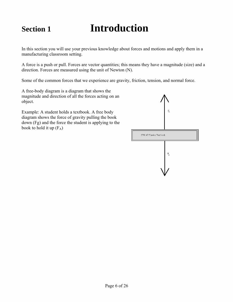
3. Can a third class lever ever have an IMA that is greater than 1? (explain your answer) 4. A drill press, (shown below on the left) contains an electric motor that drives a pulley with a
variable diameter (shown below on the right). The smallest diameter is 4.0 cm and the largest diameter is 10 cm. A belt from this pulley goes around another identical pulley attached to the drill. Find the following:
a). the largest ideal mechanical advantage possible with these two pulleys. b) the smallest ideal mechanical advantage possible with these two pulleys.
Page 26 of 26
![Designing Contextualized Learning · Designing Contextualized Learning Marcus Specht [marcus.specht@ou.nl], Educational Technology Expertise Centre, Open Universiteit Nederlands,](https://img.pdfslide.us/doc/110x75/600a6e9f96d1e569916acb11/designing-contextualized-learning-designing-contextualized-learning-marcus-specht.jpg)


![[RELO] The Contextualized English Camp](https://img.pdfslide.us/doc/110x75/549ebc08b3795989198b4599/relo-the-contextualized-english-camp.jpg)