Embed Size (px)
Citation preview
Location IntelligenceInfrastructure Asset Management
Confirm®
Confirm Map
Version v18.10b.AM

Information in this document is subject to change without notice and does not represent a commitmenton the part of the vendor or its representatives. No part of this document may be reproduced ortransmitted in any form or by any means, electronic or mechanical, including photocopying, withoutthe written permission of Pitney Bowes Inc., One Global View, Troy, New York 12180-8399.
© 2018 Pitney Bowes. All rights reserved. MapInfo, the MapInfo logo and Confirm are trademarks ofPitney Bowes and/or its affiliates.
Corporate Headquarters:Phone: 518 285 6000Fax: 518 285 6070Sales: 800 327 8627Government Sales: 800 619 2333Technical Support: 518 285 7283http://www.pitneybowes.com/us
UK and EMEA Headquarters:Phone: 1 800 840 0001Technical Support (UK): 1 800 840 0001Technical Support (International): 44 1634 880141http://www.pitneybowes.com/uk
Asia Pacific Headquarters:Phone: 61 2 9437 6255Fax: 61 2 9439 1773Technical Support: 1 800 648 899www.pitneybowes.com.au/software
Contact information for all Pitney Bowes offices is located at: http://www.pitneybowes.com/uk/contact-us.
Products named herein may be trademarks of their respective manufacturers and are hereby recognized.Trademarked names are used editorially, to the benefit of the trademark owner, with no intent to infringeon the trademark.
Open Source Attribution NoticeThe Confirm suite of products contain the following open source software:
• Feature Data Objects v 3.5.0, which is licensed under GNU Lesser General Public License, Version2.1, February 1999 with the unRAR restriction. The license can be downloaded from: http://fdo.os-geo.org/licenceAndGovernance.html. The source code for this software is available from ht-tp://fdo.osgeo.org/content/fdo-350-downloads
• MrSID software (specifically the mrsid32.dll) is used under license and is Copyright © 1995-2002,LizardTech, Inc., 1008 Western Ave., Suite 200, Seattle, WA 98104. All rights reserved. MrSID isprotected by U.S. Patent No. 5,710,835. Foreign patents are pending. Unauthorized use or duplicationprohibited.
Patented technology in the Software was developed in part through a project at the Los AlamosNational Laboratory, funded by the U.S. Government and managed by the University of California.The U.S. Government has reserved rights in the technology, including a non-exclusive, nontransfer-able, irrevocable, paid-up license to practice or have practiced throughout the world, for or on behalfof the United States, inventions covered by the patent, and has other rights under 35 U.S.C. § 200-212 and applicable implementing regulations.
For further information, contact Lizardtech.

• NodaTime, version number 1.3.10, which is licensed under the Apache license, version number 2.0.The license can be downloaded from http://www.apache.org/licenses/LICENSE-2.0 . The sourcecode for this software is available from http://nodatime.org/.
• Chromium Embedded Framework, version 3, which is licensed under the New BSD License. The li-cense can be downloaded from http://opensource.org/licenses/BSD-3-Clause. The source code forthis software is available from http://code.google.com/p/chromiumembedded/downloads/list.
• Xilium.CefGlue, version 3, which is licensed under the MIT License (with portions licensed underthe New BSD License). The licenses can be downloaded from http://opensource.org/licenses/MITand http://opensource.org/licenses/BSD-3-Clause. The source code for this software is availablefrom http://xilium.bitbucket.org/cefglue/.
• D3 Data Driven Documentation, version 3.4.1, which is licensed under the New BSD License. Thelicense can be downloaded from from https://github.com/mbostock/d3/blob/master/LICENSE. Thesource code for this software is available from http://d3js.org/.
• OpenLayers, version 2.12, which is licensed under the Modified BSD License. The license can bedownloaded from http://svn.openlayers.org/trunk/openlayers/license.txt. The source code for thissoftware is available from http://trac.osgeo.org/openlayers/browser.
• OpenLayers, version 3, which is licensed under the BSD 2-Clause Licence. The license which canbe downloaded from https://github.com/openlayers/ol3/blob/master/LICENSE.md. The source codefor this software is available from https://github.com/openlayers/ol3.
• Proj4js, version 1+, which is licensed under the Apache License, Version 2, January 2004.The licensecan be downloaded from http://www.apache.org/licenses/LICENSE-2.0.html. The source code forthis software is available from http://trac.osgeo.org/proj4js/.
• requireJS, version 2.1.2, which is licensed under the MIT License or the New BSD License.The licensecan be downloaded from https://github.com/jrburke/requirejs/blob/master/LICENSE. The sourcecode for this software is available from http://requirejs.org/.
• Apache Cordova, version 4.2.0, which is licensed under the Apache License, Version 2, January2004. The license can be downloaded from http://www.apache.org/licenses/LICENSE-2.0.html. Thesource code for this software is available from http://phonegap.com/download/.
May 08, 2018
Table of Contents
Map
Map 7
Workspace Toolbar 7
Map Toolbar 7
Confirm Toolbar 10
Viewing Features on the Map 19
Updating FeatureCoordinates via theMap 19
Object Properties Palette 20
Viewing Data on the Map 21
GPS Tracking 22
Map Workspace Manager 25
Workspace Toolbar 26
Workspace Properties 28
Workspace Layers 29
Registered Layers 38
Layer Control Window 41
Feature Map Layer Import 47
Update Entity Geometry 49
Map System Settings 50
Web Map Symbol Settings 53
Web Map Layer Settings 55
RouteShoot 56
Features on the Map 58
Confirm Database Map Layers 59
Maintaining Map Layers via ThirdParty Mapping Links 59
FAQ 61
Editing SDE Layers 61
Editing Oracle Spatial Layers 61
Coordinate Systems 62
Adding Raster Layers 62
MapThe Map module (Module number 0425) uses MapXtreme technology andsupports multiple different types of map data. These include the following:
• ESRI Shapefile Layers.• MapInfo Native Tab File Layers.• ESRI ArcSDE Layers.• Microsoft SQL Server Spatial Layers.• Oracle Spatial Layers.• Web Map Service (WMS) Layers.
The Map module provides the following functionality:
• Features can have a geometry defined against them and can be displayedon the Map as points, lines or polygons. The Referential Integrity Agentcan be used to maintain a separate Map Layer for each Feature Group.See the Features on the Map section below for more information.
• Confirm records with coordinates defining their location as a point (En-quiries, Defects and Jobs) can have their location displayed on the Mapfrom the relevant screens. The Referential Integrity Agent can be usedto maintain a separate Map Layer for each of the three types of record.
• Site level Map Layers can be created.• The location and spatial representation of Street Works is shown on the
Street Works screen and can be edited using the associated wizards.• A level 3 Street Gazetteer can be maintained using the NSG Manager
screen.• GPS information received from ConfirmConnect™ can be transferred to
a Map Layer by the Referential Integrity Agent, allowing the recent loca-tion of ConfirmConnect™ devices to be displayed.
There are alternatives to using the Map in the form of mappinglinks. More information on these links can be found in MaintainingMap Layers via Third Party Mapping Links on page 59 .
Note:
Referential Integrity AgentMuch of the above functionality depends on the Referential IntegrityAgent to automatically update Map Layers when records are created, editedor deleted within Confirm.
In this section
Map 7Map Workspace Manager 25Feature Map Layer Import 47Update Entity Geometry 49Map System Settings 50Web Map Symbol Settings 53

Web Map Layer Settings 55RouteShoot 56Features on the Map 58FAQ 61
6 of 62Pitney Bowes
Map
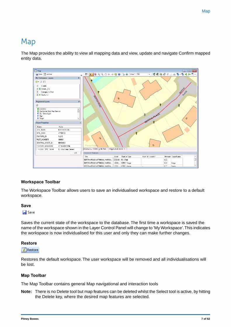
MapThe Map provides the ability to view all mapping data and view, update and navigate Confirm mappedentity data.
Workspace Toolbar
The Workspace Toolbar allows users to save an individualised workspace and restore to a defaultworkspace.
Save
Saves the current state of the workspace to the database. The first time a workspace is saved thename of the workspace shown in the Layer Control Panel will change to 'My Workspace'.This indicatesthe workspace is now individualised for this user and only they can make further changes.
Restore
Restores the default workspace. The user workspace will be removed and all individualisations willbe lost.
Map Toolbar
The Map Toolbar contains general Map navigational and interaction tools
There is no Delete tool but map features can be deleted whilst the Select tool is active, by hittingthe Delete key, where the desired map features are selected.
Note:
7 of 62Pitney Bowes
Map
.
Hide Layer Panel
This button will hide the Layer Control Palette. Once clicked, it will be renamed 'Show Layer Panel'which, when clicked, will restore the Layer Control Palette.
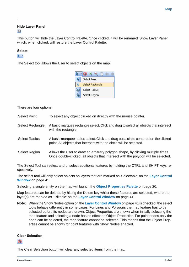
Select
The Select tool allows the User to select objects on the map.
There are four options:
To select any object clicked on directly with the mouse pointer.Select Point
A basic marquee rectangle select. Click and drag to select all objects that intersectwith the rectangle.
Select Rectangle
A basic marquee radius select. Click and drag out a circle centered on the clickedpoint. All objects that intersect with the circle will be selected.
Select Radius
Allows the User to draw an arbitrary polygon shape, by clicking multiple times.Once double-clicked, all objects that intersect with the polygon will be selected.
Select Region
The Select Tool can select and unselect additional features by holding the CTRL and SHIFT keys re-spectively.
The select tool will only select objects on layers that are marked as 'Selectable' on the Layer ControlWindow on page 41.
Selecting a single entity on the map will launch the Object Properties Palette on page 20.
Map features can be deleted by hitting the Delete key whilst these features are selected, where thelayer(s) are marked as 'Editable' on the Layer Control Window on page 41.
When the Show Nodes option on the Layer Control Window on page 41 is checked, the selecttools behave differently in some cases. For Lines and Polygons the map feature has to be
Note:
selected before its nodes are drawn. Object Properties are shown when initially selecting themap feature and selecting a node has no effect on Object Properties. For point nodes only thenode can be selected, the map feature cannot be selected. This means that the Object Prop-erties cannot be shown for point features with Show Nodes enabled.
Clear Selection
The Clear Selection button will clear any selected items from the map.
8 of 62Pitney Bowes
Map
This is not available on Map Workspace Manager.Note:
Zoom In
This mode will increase the map scale (zoom in.) It works in two ways:
1. A single click will zoom one fixed zoom level, centred on the clicked location.2. Click, hold and drag to select and area. Let go of the button and the map will zoom to the selected
area.
Note:
You can also Zoom in and Out using the mouse wheel.
Press and hold the Shift key whilst using the mouse wheel to pan the screen left to right.
Press and hold the CTRL key whilst using the mouse wheel will pan the screen up and down.
Zoom Out
Clicking on the map in this mode will decrease the map scale (zoom out) centred on the clicked location.
Note:
You can also Zoom in and Out using the mouse wheel.
Press and hold the Shift key whilst using the mouse wheel to pan the screen left to right.
Press and hold the CTRL key whilst using the mouse wheel will pan the screen up and down.
Pan
Click and drag in the map view to move the map.
Note:
You can also Zoom in and Out using the mouse wheel.
Press and hold the Shift key whilst using the mouse wheel to pan the screen left to right.
Press and hold the CTRL key whilst using the mouse wheel will pan the screen up and down.
Previous
Move back to the previous view in a list of saved views. A view is saved in the list each time the zoomlevel is changed.
Next
Moves forward to the next view in the list of saved views. This button can only be used if you haveclicked the Previous button to move back through the list.
View Entire Layer
9 of 62Pitney Bowes
Map
Select this to change the current view to the full extent of the selected Layer or All Layers. Whenclicked a list box will appear allowing the User to select which layer to zoom to.
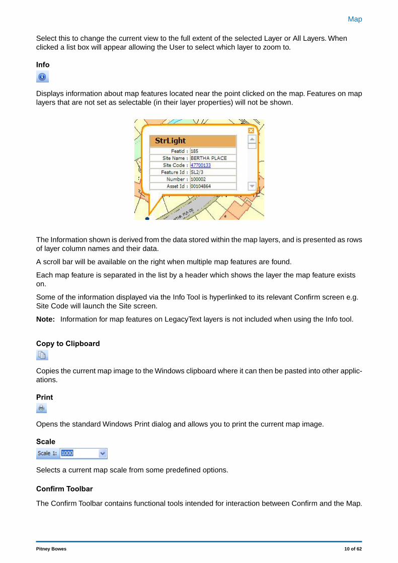
Info
Displays information about map features located near the point clicked on the map. Features on maplayers that are not set as selectable (in their layer properties) will not be shown.
The Information shown is derived from the data stored within the map layers, and is presented as rowsof layer column names and their data.
A scroll bar will be available on the right when multiple map features are found.
Each map feature is separated in the list by a header which shows the layer the map feature existson.
Some of the information displayed via the Info Tool is hyperlinked to its relevant Confirm screen e.g.Site Code will launch the Site screen.
Information for map features on LegacyText layers is not included when using the Info tool.Note:
Copy to Clipboard
Copies the current map image to the Windows clipboard where it can then be pasted into other applic-ations.
Opens the standard Windows Print dialog and allows you to print the current map image.
Scale
Selects a current map scale from some predefined options.
Confirm Toolbar
The Confirm Toolbar contains functional tools intended for interaction between Confirm and the Map.
10 of 62Pitney Bowes
Map
View Feature
The View Feature Tool allows you to view the currently selected Feature in the Confirm Feature window.
To view a Feature, use the 'Select' tool on the Map to select a one or more Features, then click on the'View' button. A Confirm Feature window will be displayed, containing the record/s for the selectedFeature/s.
Named Selection
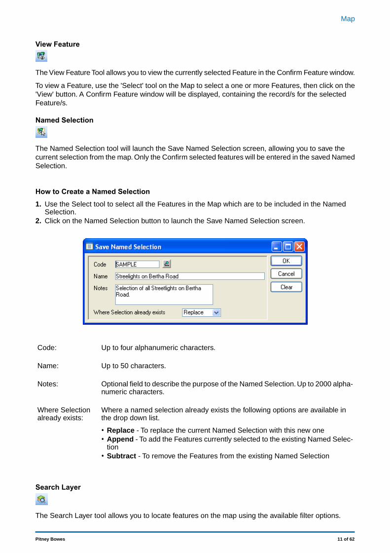
The Named Selection tool will launch the Save Named Selection screen, allowing you to save thecurrent selection from the map. Only the Confirm selected features will be entered in the saved NamedSelection.
How to Create a Named Selection1. Use the Select tool to select all the Features in the Map which are to be included in the Named
Selection.2. Click on the Named Selection button to launch the Save Named Selection screen.
Up to four alphanumeric characters.Code:
Up to 50 characters.Name:
Optional field to describe the purpose of the Named Selection. Up to 2000 alpha-numeric characters.
Notes:
Where a named selection already exists the following options are available inthe drop down list.
Where Selectionalready exists:
• Replace - To replace the current Named Selection with this new one• Append - To add the Features currently selected to the existing Named Selec-
tion• Subtract - To remove the Features from the existing Named Selection
Search Layer
The Search Layer tool allows you to locate features on the map using the available filter options.
11 of 62Pitney Bowes
Map
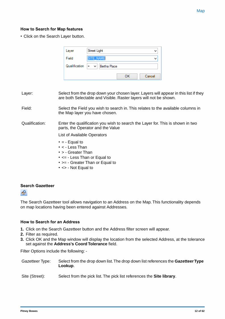
How to Search for Map features• Click on the Search Layer button.
Select from the drop down your chosen layer. Layers will appear in this list if theyare both Selectable and Visible. Raster layers will not be shown.
Layer:
Select the Field you wish to search in. This relates to the available columns inthe Map layer you have chosen.
Field:
Enter the qualification you wish to search the Layer for. This is shown in twoparts, the Operator and the Value
Qualification:
List of Available Operators
• = - Equal to• < - Less Than• > - Greater Than• <= - Less Than or Equal to• >= - Greater Than or Equal to• <> - Not Equal to
Search Gazetteer
The Search Gazetteer tool allows navigation to an Address on the Map. This functionality dependson map locations having been entered against Addresses.
How to Search for an Address1. Click on the Search Gazetteer button and the Address filter screen will appear.2. Filter as required.3. Click OK and the Map window will display the location from the selected Address, at the tolerance
set against the Address's Coord Tolerance field.
Filter Options include the following: -
Select from the drop down list.The drop down list references the Gazetteer TypeLookup.
Gazetteer Type:
Select from the pick list. The pick list references the Site library.Site (Street):
12 of 62Pitney Bowes
Map
Georeference
The 'Georeference' tool is used to record coordinates and/or a Feature/Site against the followingConfirm entities:
• Defect• Enquiry• Job• Street Works
This tool is intended to be used when a form for one of the above entities is open. For Street Works,this includes New Planned and New Immediate wizards only.
If none of these forms are open then the tool can not be used.
If more than one of these forms are open then the form last used is updated.
Any other open forms are ignored by the tool.
How to Georeference Confirm Entities
• Ensure that one of the above entity forms is open.• Click on the Georeference button to use the last selected shape type. The default is Point.• Alternatively click the arrow to the right of the button to select a shape type (either Point, Line or
Region).
The Line and Region options are only available when Georeferencing a Street Work.Note:
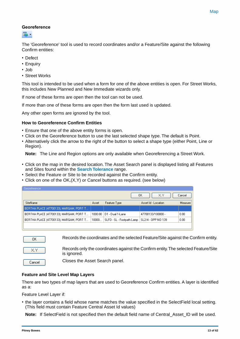
• Click on the map in the desired location. The Asset Search panel is displayed listing all Featuresand Sites found within the Search Tolerance range.
• Select the Feature or Site to be recorded against the Confirm entity.• Click on one of the OK,(X,Y) or Cancel buttons as required. (see below)
Records the coordinates and the selected Feature/Site against the Confirm entity.
Records only the coordinates against the Confirm entity.The selected Feature/Siteis ignored.
Closes the Asset Search panel.
Feature and Site Level Map Layers
There are two types of map layers that are used to Georeference Confirm entities. A layer is identifiedas a:
Feature Level Layer if:
• the layer contains a field whose name matches the value specified in the SelectField local setting.(This field must contain Feature Central Asset Id values)
If SelectField is not specified then the default field name of Central_Asset_ID will be used.Note:
13 of 62Pitney Bowes
Map
Site Level Layer if:
• the layer contains a field whose name matches the value specified in the SiteCodeField local setting.(This field must contain Site Code values)
If SiteCodeField is not specified then the default field name of Site_Code will be used.Note:
If a layer contains both the SelectField and the SiteCodeField, it is identified as a Feature LevelLayer.
Note:
Entity Information
(0430 - Entity Information module)
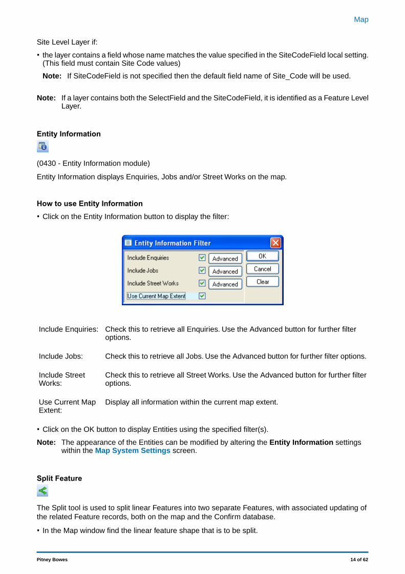
Entity Information displays Enquiries, Jobs and/or Street Works on the map.
How to use Entity Information• Click on the Entity Information button to display the filter:
Check this to retrieve all Enquiries. Use the Advanced button for further filteroptions.
Include Enquiries:
Check this to retrieve all Jobs. Use the Advanced button for further filter options.Include Jobs:
Check this to retrieve all Street Works. Use the Advanced button for further filteroptions.
Include StreetWorks:
Display all information within the current map extent.Use Current MapExtent:
• Click on the OK button to display Entities using the specified filter(s).
The appearance of the Entities can be modified by altering the Entity Information settingswithin the Map System Settings screen.
Note:
Split Feature
The Split tool is used to split linear Features into two separate Features, with associated updating ofthe related Feature records, both on the map and the Confirm database.
• In the Map window find the linear feature shape that is to be split.
14 of 62Pitney Bowes
Map
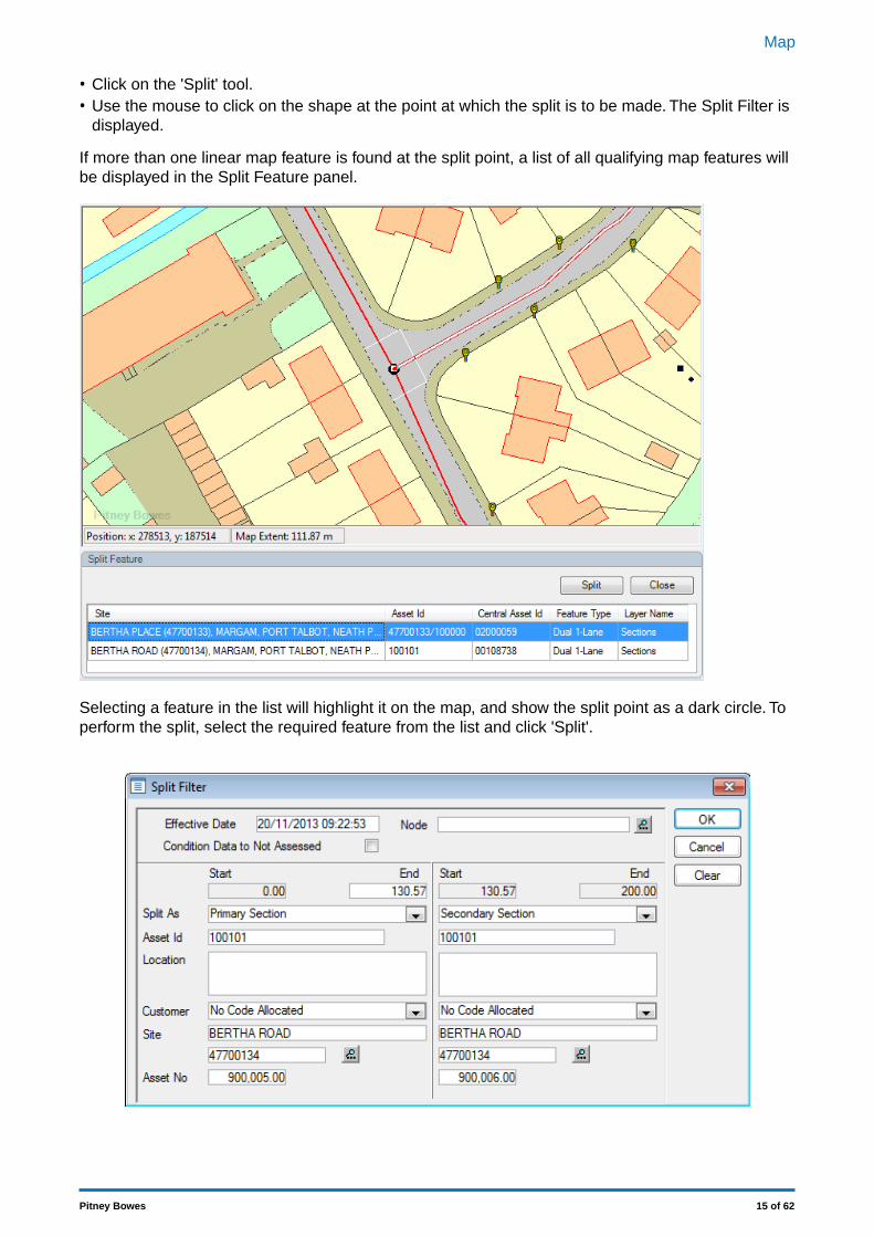
• Click on the 'Split' tool.• Use the mouse to click on the shape at the point at which the split is to be made. The Split Filter is
displayed.
If more than one linear map feature is found at the split point, a list of all qualifying map features willbe displayed in the Split Feature panel.
Selecting a feature in the list will highlight it on the map, and show the split point as a dark circle. Toperform the split, select the required feature from the list and click 'Split'.
15 of 62Pitney Bowes
Map

Sets the Start date for the new Features that will be created. This field defaultsto the current date and may be edited.
Effective Date:
Check this to remove the current condition grade from the Observation Typescarried with the new Features. The current grades will be held with the old (soonto be archived) Feature regardless of the selection made here.
Condition Data toNot Assessed:
The area of the form below the grey line is divided in half, each half representing the data that will beassigned to each of the two new Features. Both halves are completed with data relating to the currentFeature, and need to be edited to reflect the parameters of the two new Features. In particular a newand unique Plot No must be assigned to each new Feature.
Pick list ‘Split As’:
Feature that will inherit any non-chainage related data from the original Section.Primary Section:
Feature that will inherit assigned chainage referenced data appropriately.Secondary Section:
No new Feature will be created for this part of the split and referenced data willremain on the old Feature.No New Section:
Click on OK to carry out the split. The original Feature will be End Dated and archived and new Fea-ture(s) will be created according to user selection for ‘Split As’ field(s).
After successful splitting, Feature inventory should be proportionally distributed in section(s) andJobs/defects/enquiries/inspection route task records linked to feature should now point to new splitfeature or old original feature depending upon type of sections created.
There will be appropriate entries made on the 'History' tab for each of these three features (if user didnot chosen ‘No New section’ during split) otherwise it would have entry for each of two features (oldend dated feature and live feature).
Merge Feature(s)
The Merge Features tool is used to merge multiple linear Features into one linear Feature.The inform-ation from the merged Features will be combined on the new Feature to represent its entire new length.
• In the Map window select the Features to be merged.• Click on the 'Merge' tool.• The Merge Filter is displayed.
16 of 62Pitney Bowes
Map
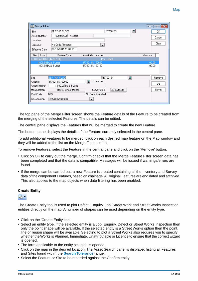
The top pane of the Merge Filter screen shows the Feature details of the Feature to be created fromthe merging of the selected Features. The details can be edited.
The central pane displays the Features that will be merged to create the new Feature.
The bottom pane displays the details of the Feature currently selected in the central pane.
To add additional Features to be merged, click on each desired map feature on the Map window andthey will be added to the list on the Merge Filter screen.
To remove Features, select the Feature in the central pane and click on the 'Remove' button.
• Click on OK to carry out the merge. Confirm checks that the Merge Feature Filter screen data hasbeen completed and that the data is compatible. Messages will be issued if warnings/errors arefound.
• If the merge can be carried out, a new Feature is created containing all the Inventory and Surveydata of the component Features, based on chainage. All original Features are end dated and archived.This also applies to the map objects when date filtering has been enabled.
Create Entity
The Create Entity tool is used to plot Defect, Enquiry, Job, Street Work and Street Works Inspectionentities directly on the map. A number of shapes can be used depending on the entity type.
• Click on the 'Create Entity' tool.• Select an entity type. If the selected entity is a Job, Enquiry, Defect or Street Works Inspection then
only the point shape will be available. If the selected entity is a Street Works option then the point,line or region shape will be available. Selecting to plot a Street Works also requires you to specifywhether the Works is Planned, Immediate, Unattributable or Licence to ensure that the correct wizardis opened.
• The form applicable to the entity selected is opened.• Click on the map in the desired location. The Asset Search panel is displayed listing all Features
and Sites found within the Search Tolerance range.• Select the Feature or Site to be recorded against the Confirm entity.
17 of 62Pitney Bowes
Map
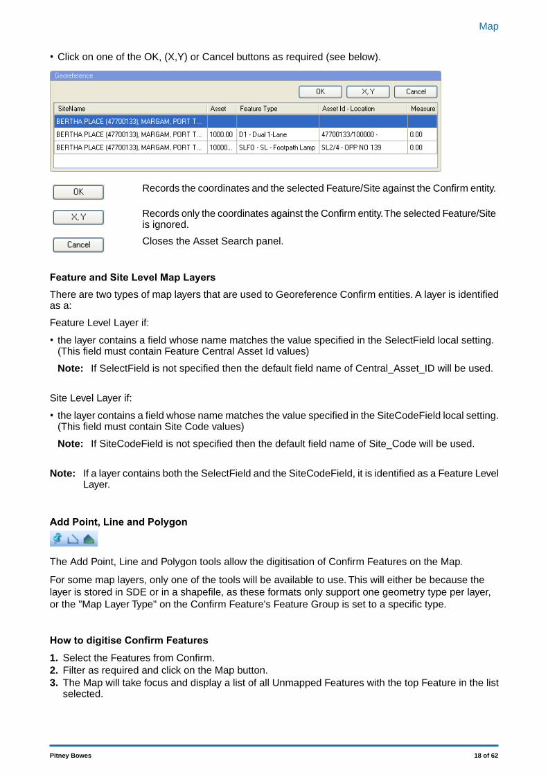
• Click on one of the OK, (X,Y) or Cancel buttons as required (see below).
Records the coordinates and the selected Feature/Site against the Confirm entity.
Records only the coordinates against the Confirm entity.The selected Feature/Siteis ignored.
Closes the Asset Search panel.
Feature and Site Level Map LayersThere are two types of map layers that are used to Georeference Confirm entities. A layer is identifiedas a:
Feature Level Layer if:
• the layer contains a field whose name matches the value specified in the SelectField local setting.(This field must contain Feature Central Asset Id values)
If SelectField is not specified then the default field name of Central_Asset_ID will be used.Note:
Site Level Layer if:
• the layer contains a field whose name matches the value specified in the SiteCodeField local setting.(This field must contain Site Code values)
If SiteCodeField is not specified then the default field name of Site_Code will be used.Note:
If a layer contains both the SelectField and the SiteCodeField, it is identified as a Feature LevelLayer.
Note:
Add Point, Line and Polygon
The Add Point, Line and Polygon tools allow the digitisation of Confirm Features on the Map.
For some map layers, only one of the tools will be available to use. This will either be because thelayer is stored in SDE or in a shapefile, as these formats only support one geometry type per layer,or the "Map Layer Type" on the Confirm Feature's Feature Group is set to a specific type.
How to digitise Confirm Features1. Select the Features from Confirm.2. Filter as required and click on the Map button.3. The Map will take focus and display a list of all Unmapped Features with the top Feature in the list
selected.
18 of 62Pitney Bowes
Map
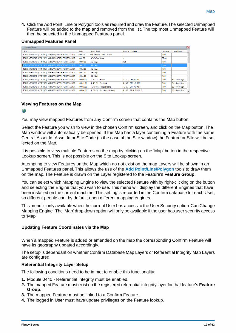
4. Click the Add Point, Line or Polygon tools as required and draw the Feature.The selected UnmappedFeature will be added to the map and removed from the list. The top most Unmapped Feature willthen be selected in the Unmapped Features panel.
Unmapped Features Panel
Viewing Features on the Map
You may view mapped Features from any Confirm screen that contains the Map button.
Select the Feature you wish to view in the chosen Confirm screen, and click on the Map button. TheMap window will automatically be opened. If the Map has a layer containing a Feature with the sameCentral Asset Id, Asset Id or Site Code (in the case of the Site window) the Feature or Site will be se-lected on the Map.
It is possible to view multiple Features on the map by clicking on the 'Map' button in the respectiveLookup screen. This is not possible on the Site Lookup screen.
Attempting to view Features on the Map which do not exist on the map Layers will be shown in anUnmapped Features panel. This allows the use of the Add Point/Line/Polygon tools to draw themon the map. The Feature is drawn on the Layer registered to the Feature's Feature Group.
You can select which Mapping Engine to view the selected Feature with by right-clicking on the buttonand selecting the Engine that you wish to use. This menu will display the different Engines that havebeen installed on the current machine.This setting is recorded in the Confirm database for each User,so different people can, by default, open different mapping engines.
This menu is only available when the current User has access to the User Security option 'Can ChangeMapping Engine'.The 'Map' drop down option will only be available if the user has user security accessto 'Map'.
Updating Feature Coordinates via the Map
When a mapped Feature is added or amended on the map the corresponding Confirm Feature willhave its geography updated accordingly.
The setup is dependant on whether Confirm Database Map Layers or Referential Integrity Map Layersare configured.
Referential Integrity Layer Setup
The following conditions need to be in met to enable this functionality:
1. Module 0440 - Referential Integrity must be enabled.2. The mapped Feature must exist on the registered referential integrity layer for that feature's Feature
Group.3. The mapped Feature must be linked to a Confirm Feature.4. The logged in User must have update privileges on the Feature lookup.
19 of 62Pitney Bowes
Map
Performing any of these actions on the map will result in the geography being updated on the ConfirmFeature:
• Adding a mapped Feature on the map that is linked to a Confirm Feature.• Moving a mapped Features node(s) on the map.• Adding a node(s) to a mapped Feature on the map.• Deleting a node(s) of a mapped Feature on the map.• Editing a mapped Feature using the 'Link' button on the mapped Features properties panel.• Splitting and/or Merging mapped Feature's.
Confirm Database Map Layer Setup
The following conditions need to be in met to enable this functionality:
1. The mapped Feature must belong to a Feature Group that has its ' Use Confirm Database MapLayer' option selected on the Feature Group lookup.
2. The mapped Feature must exist on the configured Confirm Database Map Layer.3. The mapped Feature must be linked to a Confirm Feature.4. The logged in User must have update privileges on the Feature lookup.
Performing any of these actions on the map will result in the geography being updated on the ConfirmFeature:
• Adding a mapped Feature on the map that is linked to a Confirm Feature.• Moving a mapped Features node(s) on the map.• Adding a node(s) to a mapped Feature on the map.• Deleting a node(s) of a mapped Feature on the map.• Editing a mapped Feature using the 'Link' button on the mapped Features properties panel.
When adding or updating line or polygon Features on the map the extents of the bounding box for thefeature will be used.
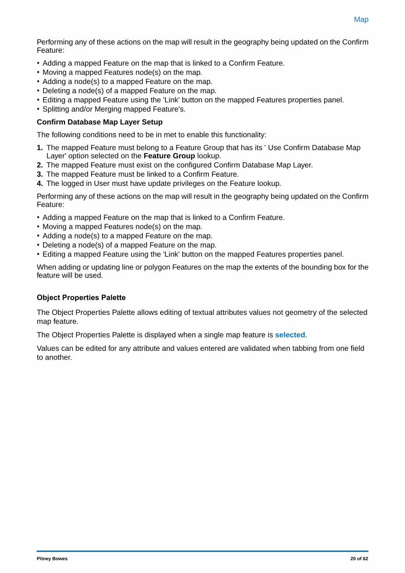
Object Properties Palette
The Object Properties Palette allows editing of textual attributes values not geometry of the selectedmap feature.
The Object Properties Palette is displayed when a single map feature is selected.
Values can be edited for any attribute and values entered are validated when tabbing from one fieldto another.
20 of 62Pitney Bowes
Map
Textual attributes will be editable only if the layer is marked as 'editable'.Note:
To mark a layer editable, Open the Layer Control Window on page 41 and select the layer. In theOptions tab, tick the 'Editable' setting.
Shape files are non-selectable.Thus shape file features textual attributes can neither be viewednor be edited.
Note:
The Link button is used to link an Unmapped Feature with the currently selected map feature.
The Link button is disabled in the following scenarios:Note:
• If the map feature is on a layer which is not registered to the Feature Group of the selectedUnmapped Feature.
• If the map layer is not visible, selectable or editable.• The Feature Group of the selected Unmapped Feature is using a Confirm Database Map
Layer.
The Link button will not be visible if the Unmapped Features panel is not open.Note:
Viewing Data on the Map
Data meeting the conditions for viewing on the map can be saved as map layers and shown on themap.
How to display data on the Map• Select the data to view by running an applicable report (e.g. Section Current Condition or Multiple
Observations List) or Data Source (see Viewing data sources on the map).• Click on the Map button in the Report preview window / Data Query Preview screen.• The Save Layer dialogue is displayed. Specify a file name and location and click 'Save'. The data
can be saved as a MapInfo Tab layer or an ESRI Shapefile layer.• The created layer is added to the Map and appears in different ways according to the data being
shown.• 1. For Dynamic Segmentation there are plot lines parallel to the Feature's spatial representation.
21 of 62Pitney Bowes
Map
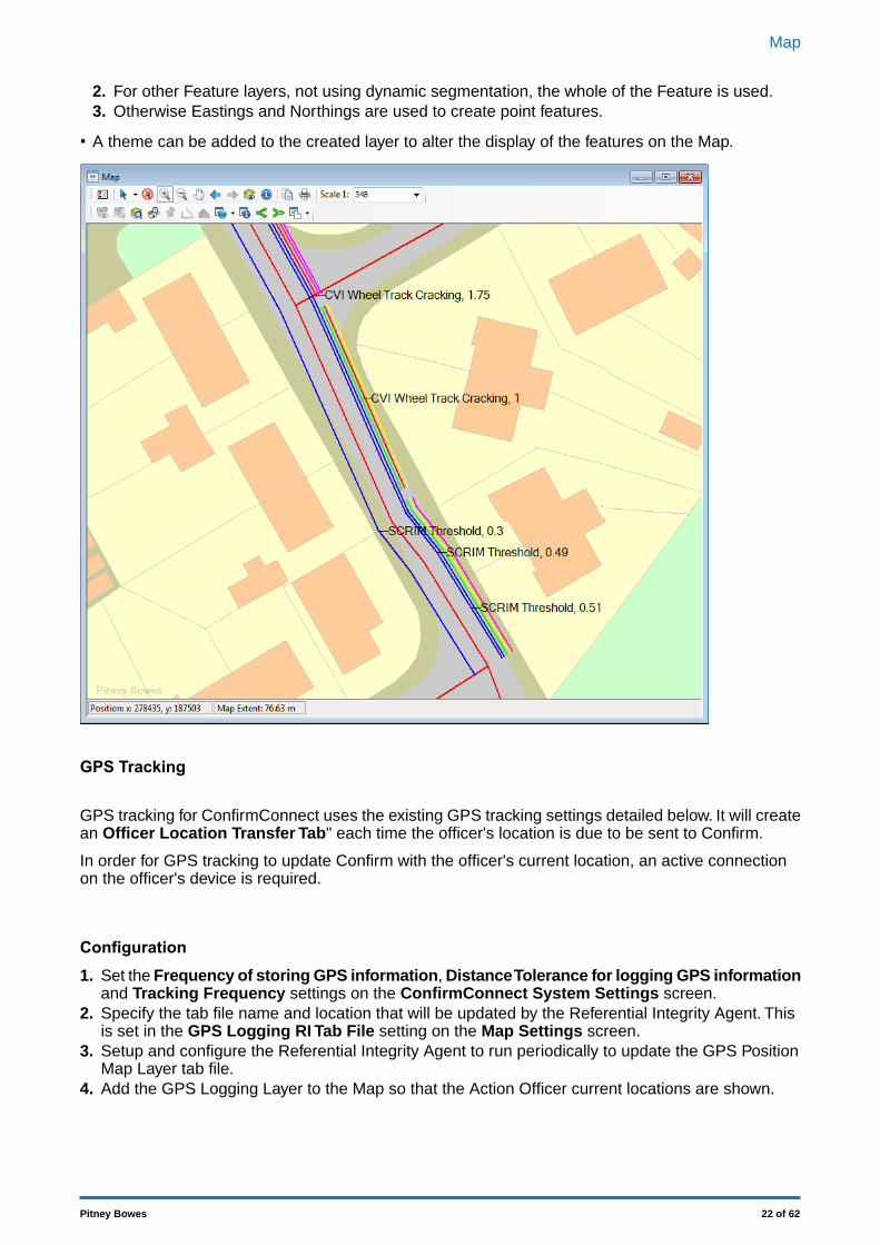
2. For other Feature layers, not using dynamic segmentation, the whole of the Feature is used.3. Otherwise Eastings and Northings are used to create point features.
• A theme can be added to the created layer to alter the display of the features on the Map.
GPS Tracking
GPS tracking for ConfirmConnect uses the existing GPS tracking settings detailed below. It will createan Officer Location Transfer Tab" each time the officer's location is due to be sent to Confirm.
In order for GPS tracking to update Confirm with the officer's current location, an active connectionon the officer's device is required.
Configuration1. Set the Frequency of storing GPS information, Distance Tolerance for logging GPS information
and Tracking Frequency settings on the ConfirmConnect System Settings screen.2. Specify the tab file name and location that will be updated by the Referential Integrity Agent. This
is set in the GPS Logging RI Tab File setting on the Map Settings screen.3. Setup and configure the Referential Integrity Agent to run periodically to update the GPS Position
Map Layer tab file.4. Add the GPS Logging Layer to the Map so that the Action Officer current locations are shown.
22 of 62Pitney Bowes
Map
Can GPS Tracking be turned off?Yes, entering 0 in the Tracking Frequency setting on the ConfirmConnect Settings screen willprevent the device from sending the officer location data up to Confirm.
Tracking in the ForegroundForeground operation applies only when ConfirmConnect is the active application on the device.
ConfirmConnect will use the Frequency of storing GPS to track Officer's location on the device andupload to the server at the Tracking Frequency interval.
Tracking in the backgroundBackground operation applies when any of the following applies:
• A different application is active (e.g. taking a phone call, reading emails)• After pressing the home key• When the device goes to sleep or is in standby mode
For Android and iOS devices, a combination of the Frequency of storing GPS and the DistanceTolerance settings are used. In background mode activity, i.e. movement, is used as the trigger fortracking, rather than being time based.
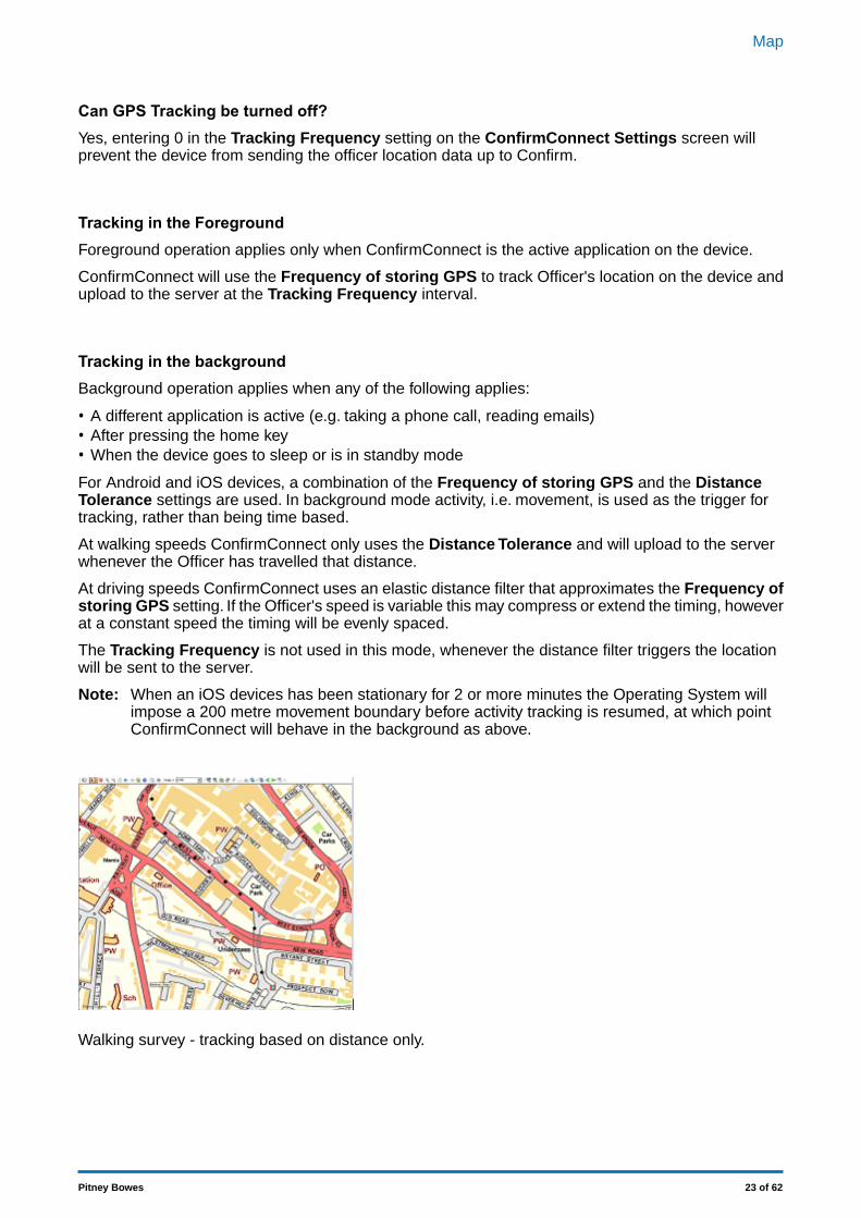
At walking speeds ConfirmConnect only uses the Distance Tolerance and will upload to the serverwhenever the Officer has travelled that distance.
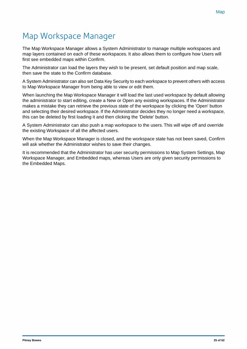
At driving speeds ConfirmConnect uses an elastic distance filter that approximates the Frequency ofstoring GPS setting. If the Officer's speed is variable this may compress or extend the timing, howeverat a constant speed the timing will be evenly spaced.
The Tracking Frequency is not used in this mode, whenever the distance filter triggers the locationwill be sent to the server.
When an iOS devices has been stationary for 2 or more minutes the Operating System willimpose a 200 metre movement boundary before activity tracking is resumed, at which pointConfirmConnect will behave in the background as above.
Note:
Walking survey - tracking based on distance only.
23 of 62Pitney Bowes
Map
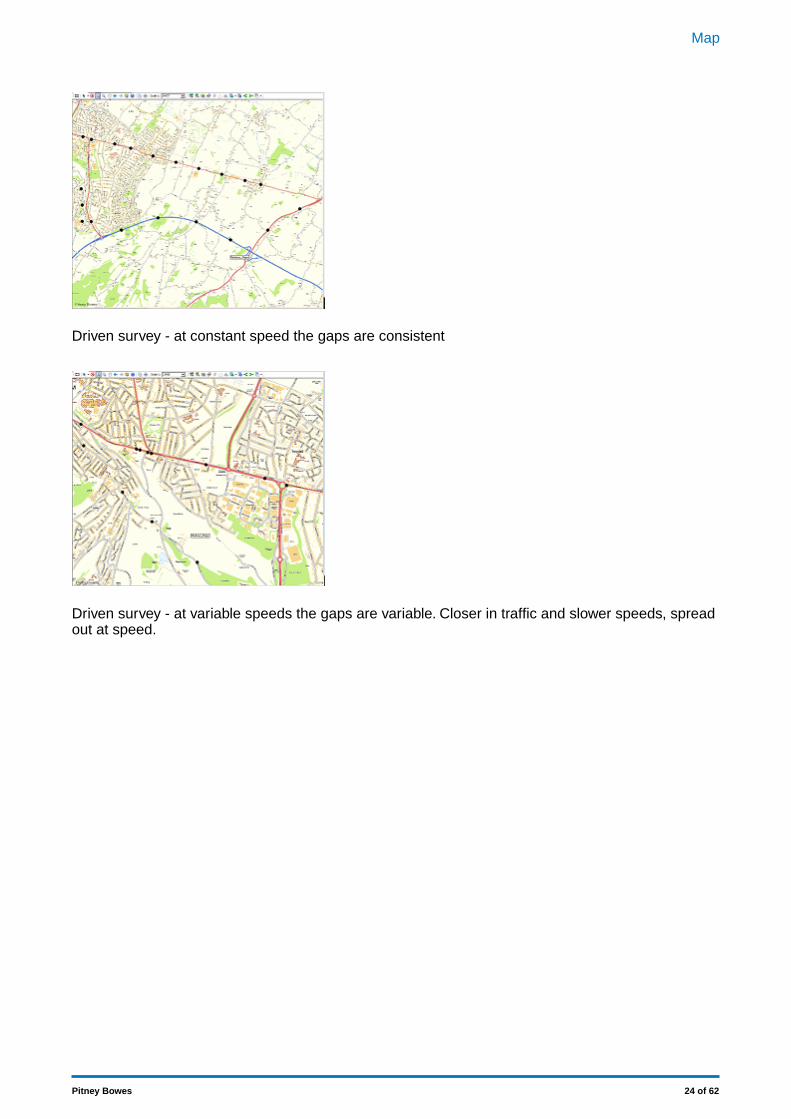
Driven survey - at constant speed the gaps are consistent
Driven survey - at variable speeds the gaps are variable. Closer in traffic and slower speeds, spreadout at speed.
24 of 62Pitney Bowes
Map
Map Workspace ManagerThe Map Workspace Manager allows a System Administrator to manage multiple workspaces andmap layers contained on each of these workspaces. It also allows them to configure how Users willfirst see embedded maps within Confirm.
The Administrator can load the layers they wish to be present, set default position and map scale,then save the state to the Confirm database.
A System Administrator can also set Data Key Security to each workspace to prevent others with accessto Map Workspace Manager from being able to view or edit them.
When launching the Map Workspace Manager it will load the last used workspace by default allowingthe administrator to start editing, create a New or Open any existing workspaces. If the Administratormakes a mistake they can retrieve the previous state of the workspace by clicking the 'Open' buttonand selecting their desired workspace. If the Administrator decides they no longer need a workspace,this can be deleted by first loading it and then clicking the 'Delete' button.
A System Administrator can also push a map workspace to the users. This will wipe off and overridethe existing Workspace of all the affected users.
When the Map Workspace Manager is closed, and the workspace state has not been saved, Confirmwill ask whether the Administrator wishes to save their changes.
It is recommended that the Administrator has user security permissions to Map System Settings, MapWorkspace Manager, and Embedded maps, whereas Users are only given security permissions tothe Embedded Maps.
25 of 62Pitney Bowes
Map
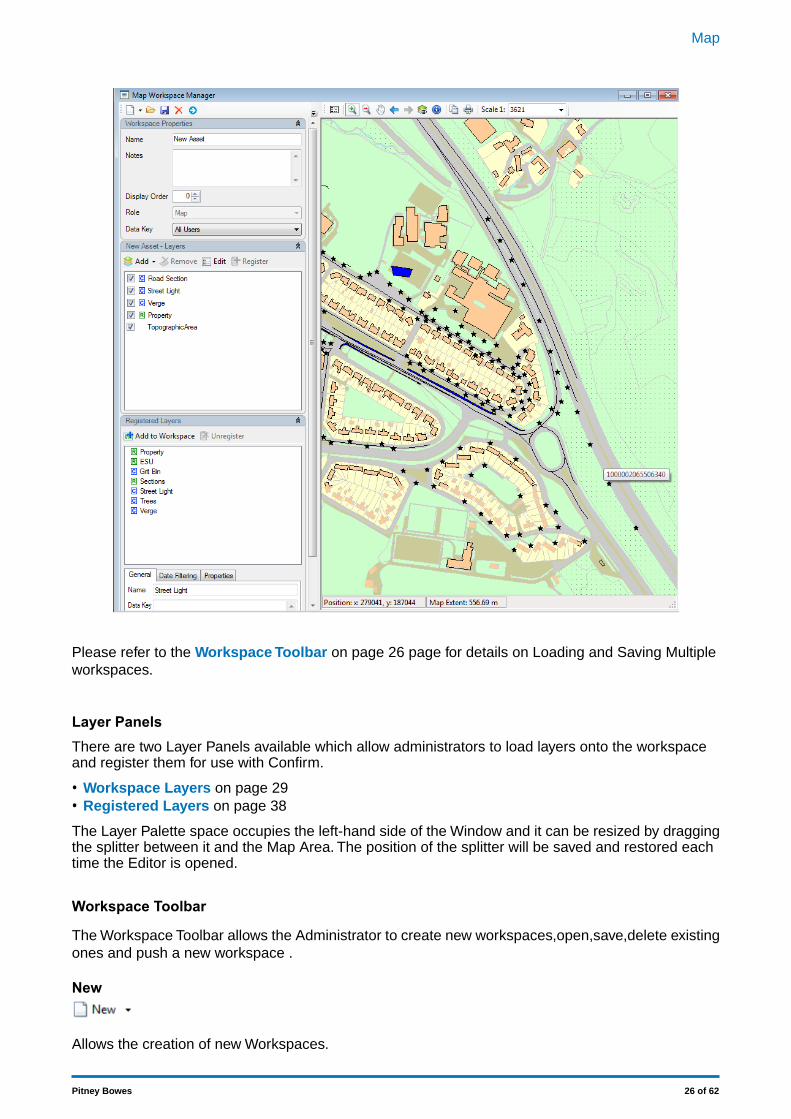
Please refer to the Workspace Toolbar on page 26 page for details on Loading and Saving Multipleworkspaces.
Layer PanelsThere are two Layer Panels available which allow administrators to load layers onto the workspaceand register them for use with Confirm.
• Workspace Layers on page 29• Registered Layers on page 38
The Layer Palette space occupies the left-hand side of the Window and it can be resized by draggingthe splitter between it and the Map Area. The position of the splitter will be saved and restored eachtime the Editor is opened.
Workspace Toolbar
The Workspace Toolbar allows the Administrator to create new workspaces,open,save,delete existingones and push a new workspace .
New
Allows the creation of new Workspaces.
26 of 62Pitney Bowes
Map
A new blank workspace can be created simply by pressing the New button.
There are three options available from the drop down menu as follows:-
• 'From Existing' creates a new Workspace that includes the layers loaded from the selected work-space.
• 'From MapInfo Geoset' creates a new Workspace from a legacy MapX geoset file (*.GST).• 'From MapObjects ViewSave' creates a new Workspace from a legacy MapObjects ViewSave file
(*.TXT).
Importing a MapObjects ViewSave containing layers with numerous rendering values can takea significant amount of time. e.g. A layer with 5000 rendering values can take in excess of 40minutes to import.
Note:
The following are limitations with the import functionality:Note:
• Theme and Label files need to exist in the same folder as the Geoset or Viewsave files tobe imported correctly.
• Raster Layers (for MapObjects ViewSave) are unsupported.• OS layers (for MapObjects ViewSave) are unsupported.
Unsupported layers do not prevent other layers from importing.Note:
Open
Launches the Open Map Workspace dialog allowing any of the available workspaces to be loaded.
Only available on the Map Workspace Manager. Workspaces listed are those which the usercurrently has data key access to.
Note:
Save
Saves the current state of the loaded workspace to the database. When creating new workspaces thesave button will save the created workspace.
Once a workspace has been saved, it will be possible to assign it to a Work Group.Note:
Delete
Allows the administrator to Delete the currently loaded workspace from the Confirm database. A con-firmation message will appear.
Only available on the Map Workspace Manager.Note:
Push
The System Administrator can push a Map Workspace to other Users for which it is the defaultWorkspace.
This will override any existing individualised Workspaces of these Users, as if all these Users had in-dividually clicked ‘Restore’.
27 of 62Pitney Bowes
Map
The first time after the Push, when any such User opens the Map screen, a message is displayed in-dicating to the User that “A new workspace has been pushed by the GIS administrator.”
The Push button is enabled only when the Role of the current Workspace is set to 'Map'.Note:
The Push does not affect the currently logged in User.Note:
Defaulting
The Map Workspace tab on the Work Group screen is used to assign ‘Map’ role workspace to a WorkGroup so that users are automatically given a default workspace when they launch the Map screen.The ‘Map’ role workspace assigned to a Work Group is set as default for all users having this WorkGroup and having data key access to the workspace set. Users who do not have the ‘Map’ role work-space set in their work group or do not have data key access to the map workspace set, for them thedefault workspace will be the first ‘Map’ role workspace as per display order to which the user hasdata key access to.
Overriding
If the user makes any change to the default Map state by performing any Map function like pan, zoom,add, delete layer etc., the default Workspace is overridden for that User with an individualised Work-space.
Restoring
A User who has an individualised Workspace can click the Restore button to reset back to their defaultWorkspace.
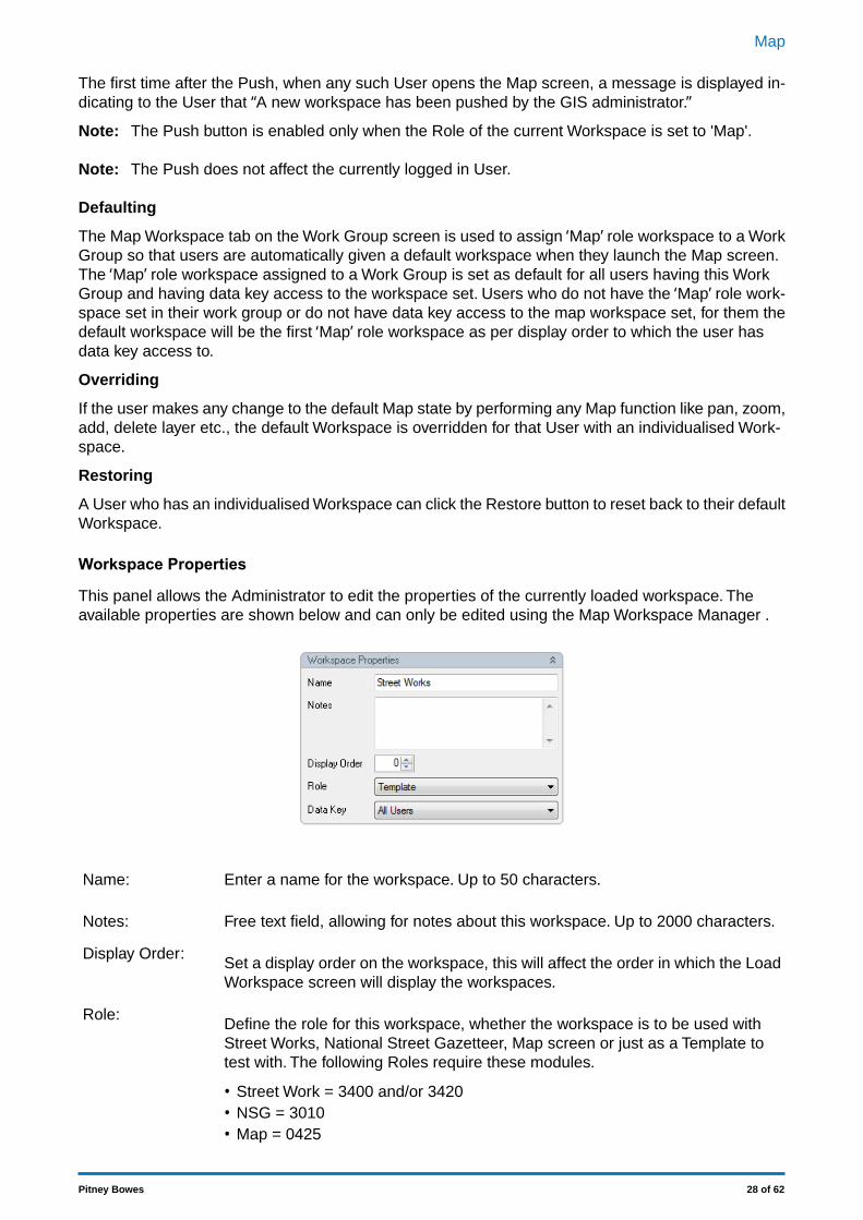
Workspace Properties
This panel allows the Administrator to edit the properties of the currently loaded workspace. Theavailable properties are shown below and can only be edited using the Map Workspace Manager .
Enter a name for the workspace. Up to 50 characters.Name:
Free text field, allowing for notes about this workspace. Up to 2000 characters.Notes:
Set a display order on the workspace, this will affect the order in which the LoadWorkspace screen will display the workspaces.
Display Order:
Define the role for this workspace, whether the workspace is to be used withStreet Works, National Street Gazetteer, Map screen or just as a Template totest with. The following Roles require these modules.
Role:
• Street Work = 3400 and/or 3420• NSG = 3010• Map = 0425
28 of 62Pitney Bowes
Map
This field is only available if the User (administrator) creating the workspace hasthe User Security setting of "Assign Data Key Manually" set. If the user does not
Data Key:
have this setting enabled then any workspace created will have its Data Key setto the "Default Data Security Key" value as set in the User Security screen.
Individual workspace map layers can be assigned a data key to give map usersedit rights as per their data security.
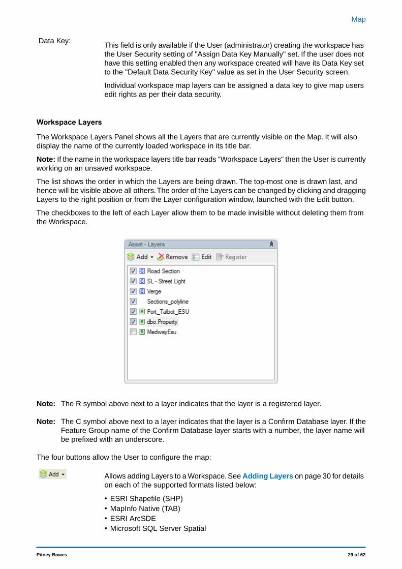
Workspace Layers
The Workspace Layers Panel shows all the Layers that are currently visible on the Map. It will alsodisplay the name of the currently loaded workspace in its title bar.
Note: If the name in the workspace layers title bar reads "Workspace Layers" then the User is currentlyworking on an unsaved workspace.
The list shows the order in which the Layers are being drawn. The top-most one is drawn last, andhence will be visible above all others.The order of the Layers can be changed by clicking and draggingLayers to the right position or from the Layer configuration window, launched with the Edit button.
The checkboxes to the left of each Layer allow them to be made invisible without deleting them fromthe Workspace.
The R symbol above next to a layer indicates that the layer is a registered layer.Note:
The C symbol above next to a layer indicates that the layer is a Confirm Database layer. If theFeature Group name of the Confirm Database layer starts with a number, the layer name willbe prefixed with an underscore.
Note:
The four buttons allow the User to configure the map:
Allows adding Layers to a Workspace. See Adding Layers on page 30 for detailson each of the supported formats listed below:
• ESRI Shapefile (SHP)• MapInfo Native (TAB)• ESRI ArcSDE• Microsoft SQL Server Spatial
29 of 62Pitney Bowes
Map
• Oracle Spatial• Web Map Service (WMS)
Deletes the Layer currently selected in the Workspace Layer Panel
Opens the MapXtreme Layer Control Window on page 41. This window allowsthe visual style of the Layer to be configured and other layer flags to be set suchas the 'selectable' flag which must be set for the Info Tool to detect objects onthis Layer when it is clicked on the map.
This button 'Registers' a Layer with Confirm. Registered layers will appear withinthe 'Registered Layers on page 38' and Confirm will remember informationabout these layers and provide additional capabilities such as Date Filtering. Anylayer in the Workspace that is Registered is shown with a small 'R' icon to theright of the checkbox.
Adding Layers
Multiple layer formats are supported in the Map Workspace Manager. Click on the Add button andselect the layer type required. The relevant sections below outline how to add each layer type.
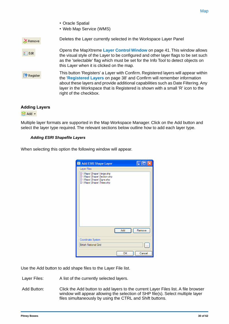
Adding ESRI Shapefile Layers
When selecting this option the following window will appear.
Use the Add button to add shape files to the Layer File list.
A list of the currently selected layers.Layer Files:
Click the Add button to add layers to the current Layer Files list. A file browserwindow will appear allowing the selection of SHP file(s). Select multiple layerfiles simultaneously by using the CTRL and Shift buttons.
Add Button:
30 of 62Pitney Bowes
Map
Select and highlight the layers you wish to remove from the Layer Files list andthen click on the Remove button to complete the action.
Remove Button:
Once the layers have been added to the Layer File list, the Coordinate System must specified.
The Coordinate System must be specified as this will set projection within theMap window for the chosen layers.
Coordinate Sys-tem:
If this is the first layer being added to the Map, the default Coordinate Systemvalue will be set from the Map System Settings screen.
If layers are already present on the Map, the default Coordinate System valuewill be set from the Maps "Coordinate system of Map" setting.
If the coordinate system specified is different to that of the Map's current coordin-ate projection the layer will be added but nothing will be displayed on that layer.
Adding MapInfo Native Tab File Layers
When adding TAB files a file browser window will appear to locate the required TAB file(s). ClickingOK makes the selection and adds the files.You can select and add multiple layer files simultaneouslyby using the CTRL and Shift buttons.
Adding ESRI ArcSDE Layers
Layers stored within an ESRI Spatial Database Engine can be added to the Workspace.
ESRI ArcSDE can be connected to directly for Oracle and SQL Server. It can also be connected tovia an ArcSDE Application Server service.
Populate values for the required ESRI ArcSDE entry as shown below:
For connections to succeed, the computer running Confirm must have an ESRI product installed,that is capable of connecting to an SDE database, for example, ArcGIS. Specifically, it must
Note:
include the sde*, pe* and sg* DLLs. The computer's Path environment variable must also beupdated to include the directory where these files exist. For example "C:\Program Files\Arc-GIS\Desktop10.0\Bin".
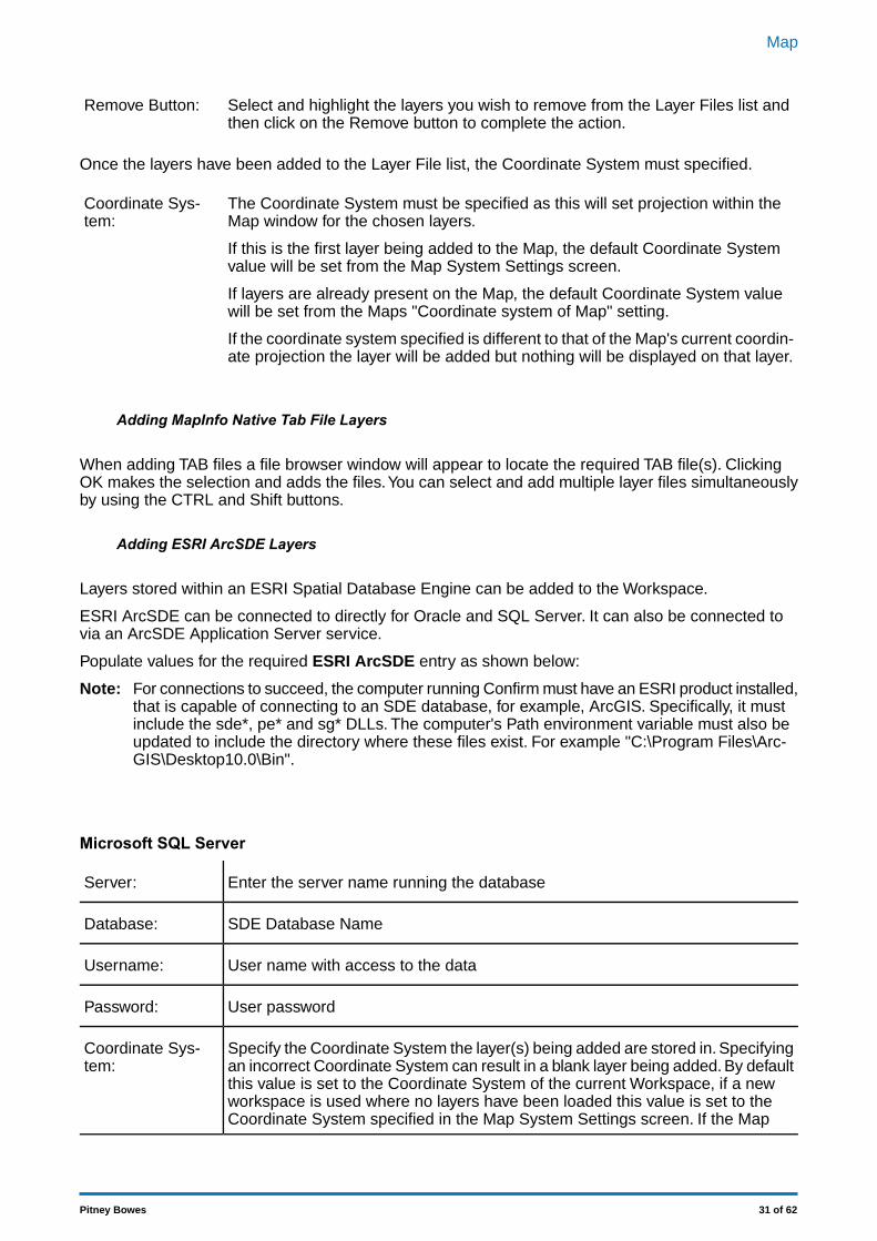
Microsoft SQL Server
Enter the server name running the databaseServer:
SDE Database NameDatabase:
User name with access to the dataUsername:
User passwordPassword:
Specify the Coordinate System the layer(s) being added are stored in. Specifyingan incorrect Coordinate System can result in a blank layer being added. By default
Coordinate Sys-tem:
this value is set to the Coordinate System of the current Workspace, if a newworkspace is used where no layers have been loaded this value is set to theCoordinate System specified in the Map System Settings screen. If the Map
31 of 62Pitney Bowes
Map
System Settings screen's Coordinate System value is not set then it will revertto Longitude / Latitude.
Click the Connect button to retrieve a list of available layers. Select one or morelayers (using CTRL and SHIFT keys) and click OK. The selected layers will beadded to the Map.
Connect Button:
The SQL Server Native Client at the appropriate version for the SQL Server hosting the SDEdatabase must be installed.
Note:
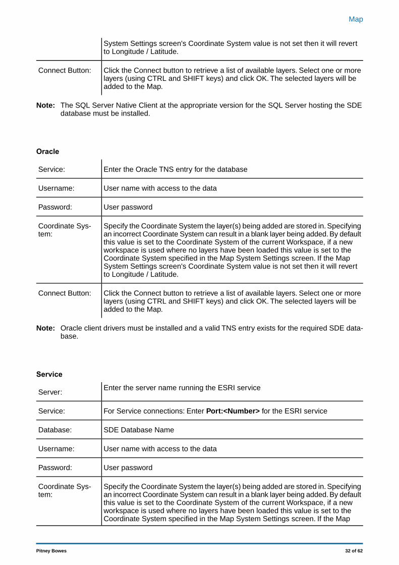
Oracle
Enter the Oracle TNS entry for the databaseService:
User name with access to the dataUsername:
User passwordPassword:
Specify the Coordinate System the layer(s) being added are stored in. Specifyingan incorrect Coordinate System can result in a blank layer being added. By default
Coordinate Sys-tem:
this value is set to the Coordinate System of the current Workspace, if a newworkspace is used where no layers have been loaded this value is set to theCoordinate System specified in the Map System Settings screen. If the MapSystem Settings screen's Coordinate System value is not set then it will revertto Longitude / Latitude.
Click the Connect button to retrieve a list of available layers. Select one or morelayers (using CTRL and SHIFT keys) and click OK. The selected layers will beadded to the Map.
Connect Button:
Oracle client drivers must be installed and a valid TNS entry exists for the required SDE data-base.
Note:
Service
Enter the server name running the ESRI serviceServer:
For Service connections: Enter Port:<Number> for the ESRI serviceService:
SDE Database NameDatabase:
User name with access to the dataUsername:
User passwordPassword:
Specify the Coordinate System the layer(s) being added are stored in. Specifyingan incorrect Coordinate System can result in a blank layer being added. By default
Coordinate Sys-tem:
this value is set to the Coordinate System of the current Workspace, if a newworkspace is used where no layers have been loaded this value is set to theCoordinate System specified in the Map System Settings screen. If the Map
32 of 62Pitney Bowes
Map
System Settings screen's Coordinate System value is not set then it will revertto Longitude / Latitude.
Click the Connect button to retrieve a list of available layers. Select one or morelayers (using CTRL and SHIFT keys) and click OK. The selected layers will beadded to the Map.
Connect Button:
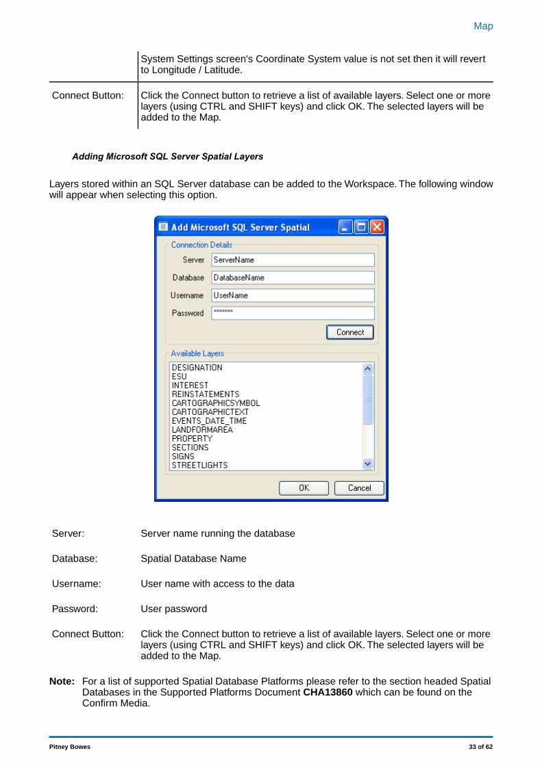
Adding Microsoft SQL Server Spatial Layers
Layers stored within an SQL Server database can be added to the Workspace. The following windowwill appear when selecting this option.
Server name running the databaseServer:
Spatial Database NameDatabase:
User name with access to the dataUsername:
User passwordPassword:
Click the Connect button to retrieve a list of available layers. Select one or morelayers (using CTRL and SHIFT keys) and click OK. The selected layers will beadded to the Map.
Connect Button:
For a list of supported Spatial Database Platforms please refer to the section headed SpatialDatabases in the Supported Platforms Document CHA13860 which can be found on theConfirm Media.
Note:
33 of 62Pitney Bowes
Map
If a SQL Server Layer is to be used for Date Filtering then the columns in the layer holding thedates must be Date/Time data types. Date only data types will not work.
Note:
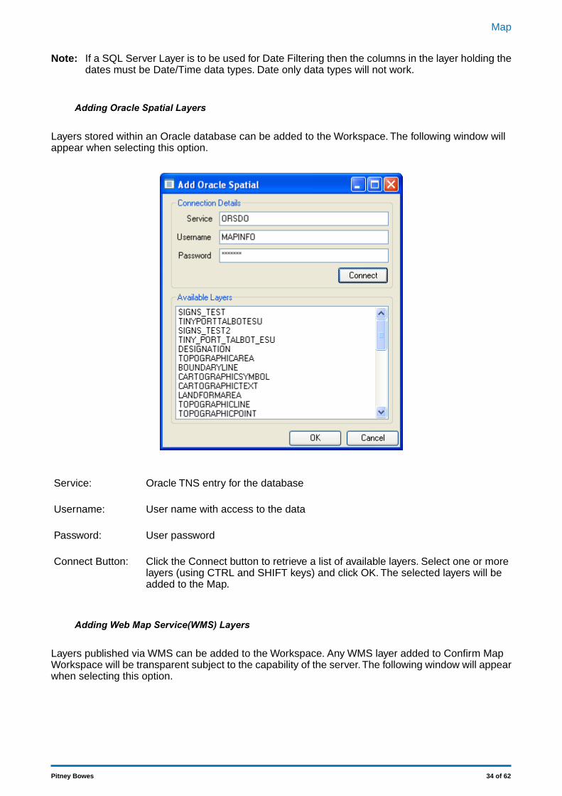
Adding Oracle Spatial Layers
Layers stored within an Oracle database can be added to the Workspace. The following window willappear when selecting this option.
Oracle TNS entry for the databaseService:
User name with access to the dataUsername:
User passwordPassword:
Click the Connect button to retrieve a list of available layers. Select one or morelayers (using CTRL and SHIFT keys) and click OK. The selected layers will beadded to the Map.
Connect Button:
Adding Web Map Service(WMS) Layers
Layers published via WMS can be added to the Workspace. Any WMS layer added to Confirm MapWorkspace will be transparent subject to the capability of the server.The following window will appearwhen selecting this option.
34 of 62Pitney Bowes
Map
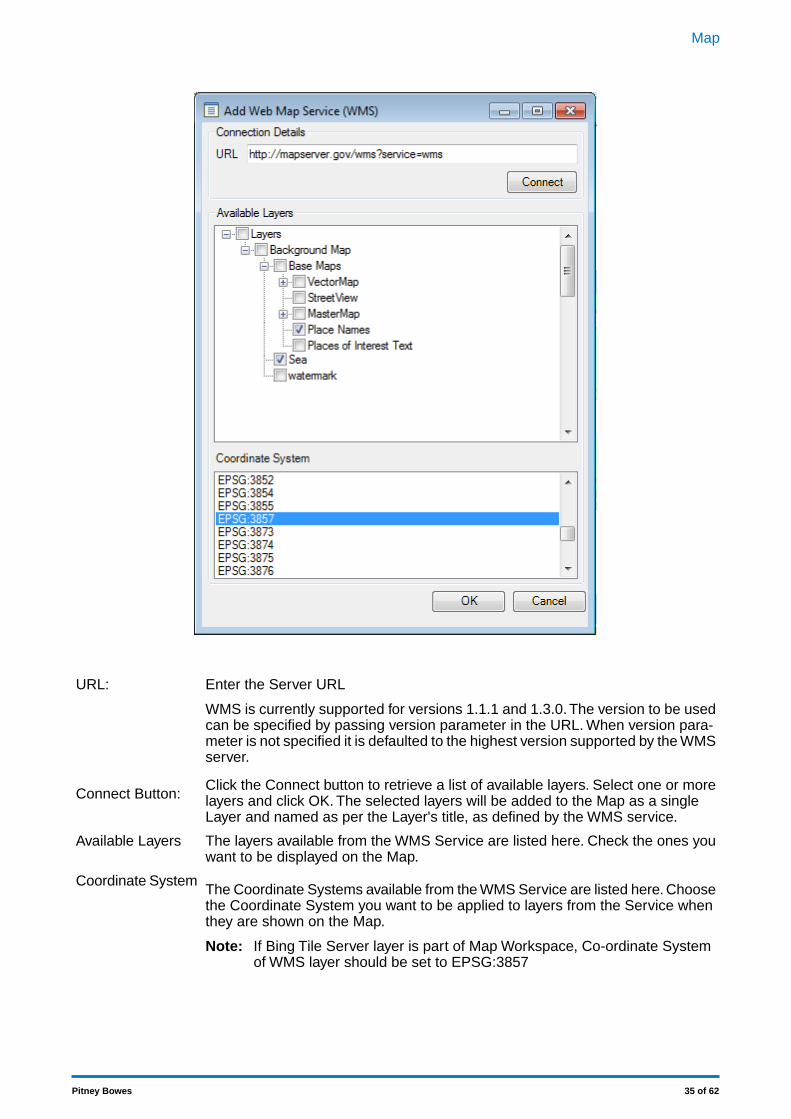
Enter the Server URLURL:
WMS is currently supported for versions 1.1.1 and 1.3.0. The version to be usedcan be specified by passing version parameter in the URL. When version para-meter is not specified it is defaulted to the highest version supported by the WMSserver.
Click the Connect button to retrieve a list of available layers. Select one or morelayers and click OK. The selected layers will be added to the Map as a singleLayer and named as per the Layer's title, as defined by the WMS service.
Connect Button:
The layers available from the WMS Service are listed here. Check the ones youwant to be displayed on the Map.
Available Layers
The Coordinate Systems available from the WMS Service are listed here. Choosethe Coordinate System you want to be applied to layers from the Service whenthey are shown on the Map.
Coordinate System
If Bing Tile Server layer is part of Map Workspace, Co-ordinate Systemof WMS layer should be set to EPSG:3857
Note:
35 of 62Pitney Bowes
Map
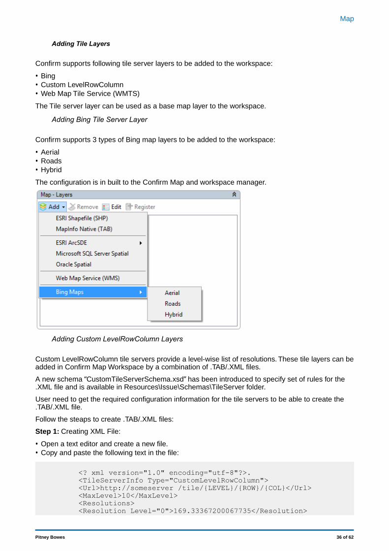
Adding Tile Layers
Confirm supports following tile server layers to be added to the workspace:
• Bing• Custom LevelRowColumn• Web Map Tile Service (WMTS)
The Tile server layer can be used as a base map layer to the workspace.
Adding Bing Tile Server Layer
Confirm supports 3 types of Bing map layers to be added to the workspace:
• Aerial• Roads• Hybrid
The configuration is in built to the Confirm Map and workspace manager.
Adding Custom LevelRowColumn Layers
Custom LevelRowColumn tile servers provide a level-wise list of resolutions. These tile layers can beadded in Confirm Map Workspace by a combination of .TAB/.XML files.
A new schema “CustomTileServerSchema.xsd” has been introduced to specify set of rules for the.XML file and is available in Resources\Issue\Schemas\TileServer folder.
User need to get the required configuration information for the tile servers to be able to create the.TAB/.XML file.
Follow the steaps to create .TAB/.XML files:
Step 1: Creating XML File:
• Open a text editor and create a new file.• Copy and paste the following text in the file:
<? xml version="1.0" encoding="utf-8"?>.<TileServerInfo Type="CustomLevelRowColumn"><Url>http://someserver /tile/{LEVEL}/{ROW}/{COL}</Url><MaxLevel>10</MaxLevel><Resolutions><Resolution Level="0">169.33367200067735</Resolution>
36 of 62Pitney Bowes
Map
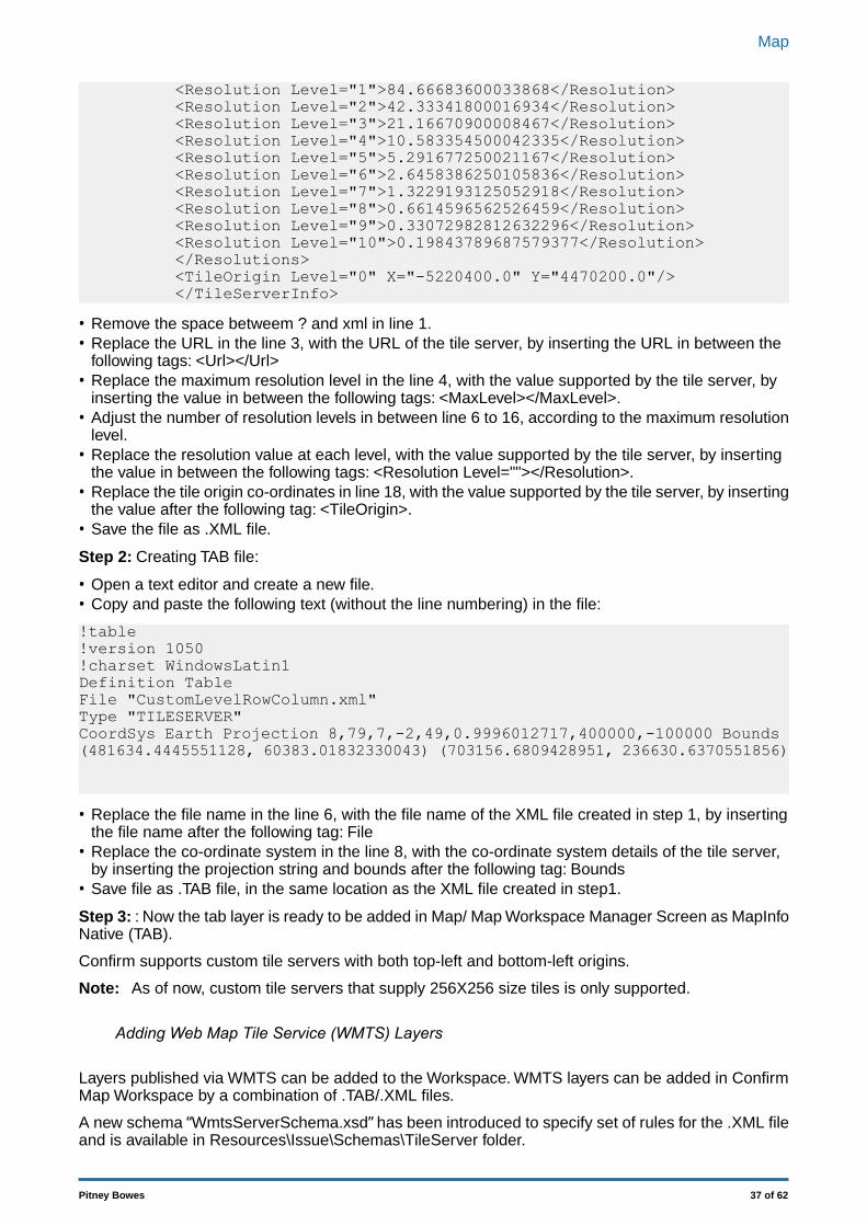
<Resolution Level="1">84.66683600033868</Resolution><Resolution Level="2">42.33341800016934</Resolution><Resolution Level="3">21.16670900008467</Resolution><Resolution Level="4">10.583354500042335</Resolution><Resolution Level="5">5.291677250021167</Resolution><Resolution Level="6">2.6458386250105836</Resolution><Resolution Level="7">1.3229193125052918</Resolution><Resolution Level="8">0.6614596562526459</Resolution><Resolution Level="9">0.33072982812632296</Resolution><Resolution Level="10">0.19843789687579377</Resolution></Resolutions><TileOrigin Level="0" X="-5220400.0" Y="4470200.0"/></TileServerInfo>
• Remove the space betweem ? and xml in line 1.• Replace the URL in the line 3, with the URL of the tile server, by inserting the URL in between the
following tags: <Url></Url>• Replace the maximum resolution level in the line 4, with the value supported by the tile server, by
inserting the value in between the following tags: <MaxLevel></MaxLevel>.• Adjust the number of resolution levels in between line 6 to 16, according to the maximum resolution
level.• Replace the resolution value at each level, with the value supported by the tile server, by inserting
the value in between the following tags: <Resolution Level=""></Resolution>.• Replace the tile origin co-ordinates in line 18, with the value supported by the tile server, by inserting
the value after the following tag: <TileOrigin>.• Save the file as .XML file.
Step 2: Creating TAB file:
• Open a text editor and create a new file.• Copy and paste the following text (without the line numbering) in the file:
!table!version 1050!charset WindowsLatin1Definition TableFile "CustomLevelRowColumn.xml"Type "TILESERVER"CoordSys Earth Projection 8,79,7,-2,49,0.9996012717,400000,-100000 Bounds(481634.4445551128, 60383.01832330043) (703156.6809428951, 236630.6370551856)
• Replace the file name in the line 6, with the file name of the XML file created in step 1, by insertingthe file name after the following tag: File
• Replace the co-ordinate system in the line 8, with the co-ordinate system details of the tile server,by inserting the projection string and bounds after the following tag: Bounds
• Save file as .TAB file, in the same location as the XML file created in step1.
Step 3: : Now the tab layer is ready to be added in Map/ Map Workspace Manager Screen as MapInfoNative (TAB).
Confirm supports custom tile servers with both top-left and bottom-left origins.
As of now, custom tile servers that supply 256X256 size tiles is only supported.Note:
Adding Web Map Tile Service (WMTS) Layers
Layers published via WMTS can be added to the Workspace. WMTS layers can be added in ConfirmMap Workspace by a combination of .TAB/.XML files.
A new schema “WmtsServerSchema.xsd” has been introduced to specify set of rules for the .XML fileand is available in Resources\Issue\Schemas\TileServer folder.
37 of 62Pitney Bowes
Map
Follow the steaps to create .TAB/.XML files:
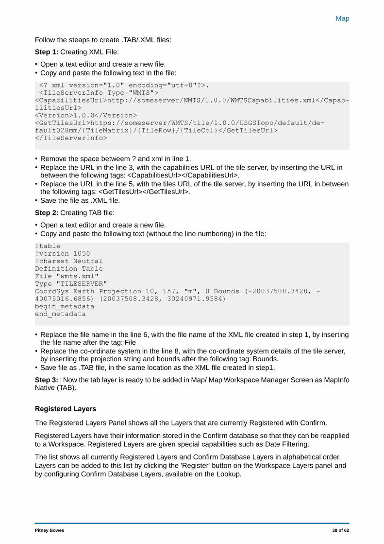
Step 1: Creating XML File:
• Open a text editor and create a new file.• Copy and paste the following text in the file:
<? xml version="1.0" encoding="utf-8"?>.<TileServerInfo Type="WMTS"><CapabilitiesUrl>http://someserver/WMTS/1.0.0/WMTSCapabilities.xml</Capab-ilitiesUrl><Version>1.0.0</Version><GetTilesUrl>https://someserver/WMTS/tile/1.0.0/USGSTopo/default/de-fault028mm/{TileMatrix}/{TileRow}/{TileCol}</GetTilesUrl></TileServerInfo>
• Remove the space betweem ? and xml in line 1.• Replace the URL in the line 3, with the capabilities URL of the tile server, by inserting the URL in
between the following tags: <CapabilitiesUrl></CapabilitiesUrl>.• Replace the URL in the line 5, with the tiles URL of the tile server, by inserting the URL in between
the following tags: <GetTilesUrl></GetTilesUrl>.• Save the file as .XML file.
Step 2: Creating TAB file:
• Open a text editor and create a new file.• Copy and paste the following text (without the line numbering) in the file:
!table!version 1050!charset NeutralDefinition TableFile "wmts.xml"Type "TILESERVER"CoordSys Earth Projection 10, 157, "m", 0 Bounds (-20037508.3428, -40075016.6856) (20037508.3428, 30240971.9584)begin_metadataend_metadata
• Replace the file name in the line 6, with the file name of the XML file created in step 1, by insertingthe file name after the tag: File
• Replace the co-ordinate system in the line 8, with the co-ordinate system details of the tile server,by inserting the projection string and bounds after the following tag: Bounds.
• Save file as .TAB file, in the same location as the XML file created in step1.
Step 3: : Now the tab layer is ready to be added in Map/ Map Workspace Manager Screen as MapInfoNative (TAB).
Registered Layers
The Registered Layers Panel shows all the Layers that are currently Registered with Confirm.
Registered Layers have their information stored in the Confirm database so that they can be reappliedto a Workspace. Registered Layers are given special capabilities such as Date Filtering.
The list shows all currently Registered Layers and Confirm Database Layers in alphabetical order.Layers can be added to this list by clicking the 'Register' button on the Workspace Layers panel andby configuring Confirm Database Layers, available on the Lookup.
38 of 62Pitney Bowes
Map
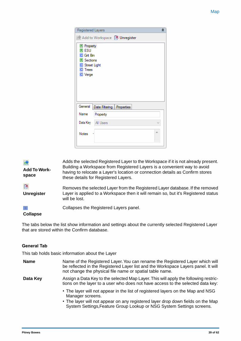
Adds the selected Registered Layer to the Workspace if it is not already present.Building a Workspace from Registered Layers is a convenient way to avoid
Add To Work-space
having to relocate a Layer's location or connection details as Confirm storesthese details for Registered Layers.
Removes the selected Layer from the Registered Layer database. If the removedLayer is applied to a Workspace then it will remain so, but it's Registered statuswill be lost.
Unregister
Collapses the Registered Layers panel.Collapse
The tabs below the list show information and settings about the currently selected Registered Layerthat are stored within the Confirm database.
General TabThis tab holds basic information about the Layer
Name of the Registered Layer.You can rename the Registered Layer which willbe reflected in the Registered Layer list and the Workspace Layers panel. It willnot change the physical file name or spatial table name.
Name
Assign a Data Key to the selected Map Layer.This will apply the following restric-tions on the layer to a user who does not have access to the selected data key:
Data Key
• The layer will not appear in the list of registered layers on the Map and NSGManager screens.
• The layer will not appear on any registered layer drop down fields on the MapSystem Settings,Feature Group Lookup or NSG System Settings screens.
39 of 62Pitney Bowes
Map
Note: Layers with an assigned data key that have already been added to aworkspace can still be viewed on the Map by a user that does not have accessto that data key.
A free-text field where the Administrator may record additional information aboutthe Layer.
Notes
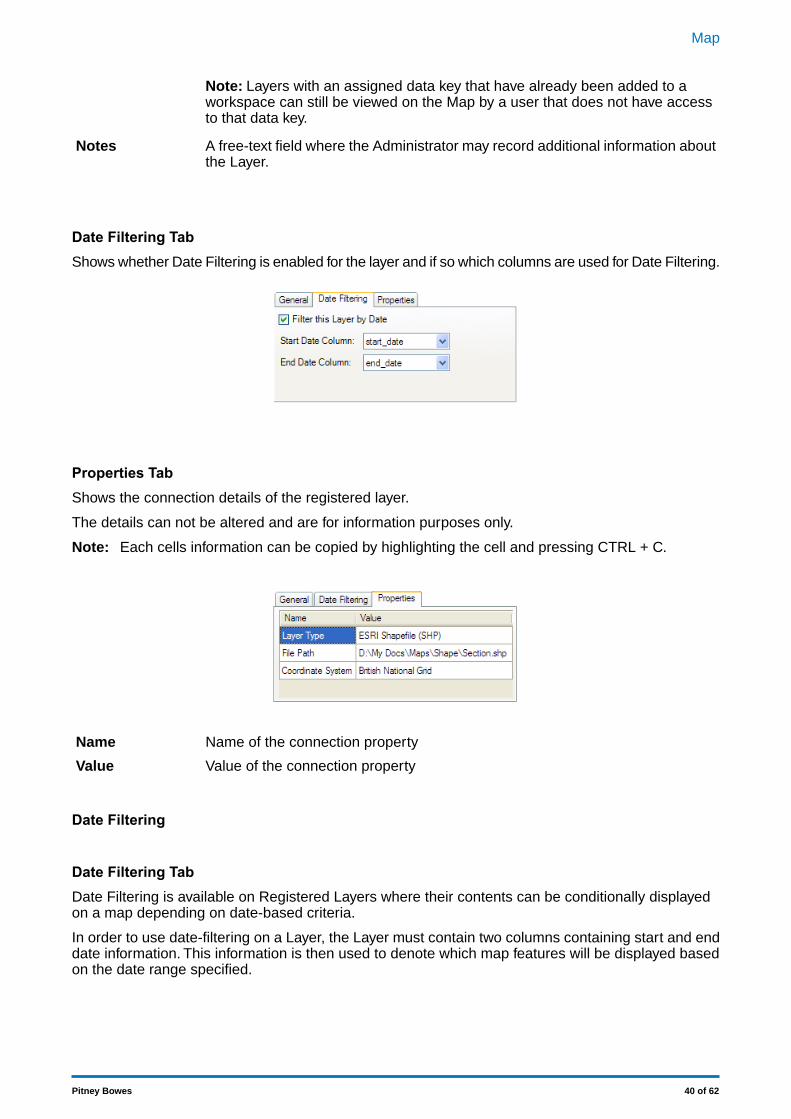
Date Filtering TabShows whether Date Filtering is enabled for the layer and if so which columns are used for Date Filtering.
Properties TabShows the connection details of the registered layer.
The details can not be altered and are for information purposes only.
Each cells information can be copied by highlighting the cell and pressing CTRL + C.Note:
Name of the connection propertyName
Value of the connection propertyValue
Date Filtering
Date Filtering TabDate Filtering is available on Registered Layers where their contents can be conditionally displayedon a map depending on date-based criteria.
In order to use date-filtering on a Layer, the Layer must contain two columns containing start and enddate information. This information is then used to denote which map features will be displayed basedon the date range specified.
40 of 62Pitney Bowes
Map
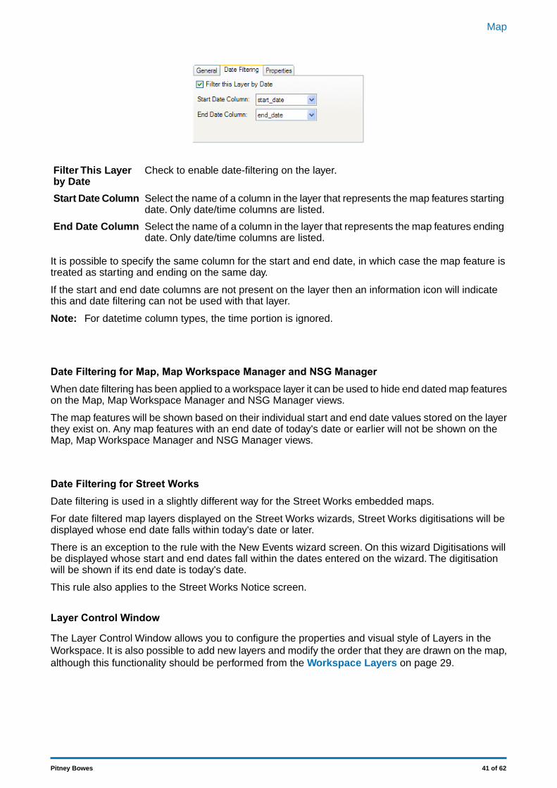
Check to enable date-filtering on the layer.Filter This Layerby Date
Select the name of a column in the layer that represents the map features startingdate. Only date/time columns are listed.
Start Date Column
Select the name of a column in the layer that represents the map features endingdate. Only date/time columns are listed.
End Date Column
It is possible to specify the same column for the start and end date, in which case the map feature istreated as starting and ending on the same day.
If the start and end date columns are not present on the layer then an information icon will indicatethis and date filtering can not be used with that layer.
For datetime column types, the time portion is ignored.Note:
Date Filtering for Map, Map Workspace Manager and NSG ManagerWhen date filtering has been applied to a workspace layer it can be used to hide end dated map featureson the Map, Map Workspace Manager and NSG Manager views.
The map features will be shown based on their individual start and end date values stored on the layerthey exist on. Any map features with an end date of today's date or earlier will not be shown on theMap, Map Workspace Manager and NSG Manager views.
Date Filtering for Street WorksDate filtering is used in a slightly different way for the Street Works embedded maps.
For date filtered map layers displayed on the Street Works wizards, Street Works digitisations will bedisplayed whose end date falls within today's date or later.
There is an exception to the rule with the New Events wizard screen. On this wizard Digitisations willbe displayed whose start and end dates fall within the dates entered on the wizard. The digitisationwill be shown if its end date is today's date.
This rule also applies to the Street Works Notice screen.
Layer Control Window
The Layer Control Window allows you to configure the properties and visual style of Layers in theWorkspace. It is also possible to add new layers and modify the order that they are drawn on the map,although this functionality should be performed from the Workspace Layers on page 29.
41 of 62Pitney Bowes
Map
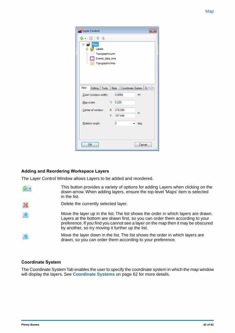
Adding and Reordering Workspace LayersThe Layer Control Window allows Layers to be added and reordered.
This button provides a variety of options for adding Layers when clicking on thedown-arrow. When adding layers, ensure the top-level 'Maps' item is selectedin the list.
Delete the currently selected layer.
Move the layer up in the list. The list shows the order in which layers are drawn.Layers at the bottom are drawn first, so you can order them according to yourpreference. If you find you cannot see a layer on the map then it may be obscuredby another, so try moving it further up the list.
Move the layer down in the list. The list shows the order in which layers aredrawn, so you can order them according to your preference.
Coordinate SystemThe Coordinate System Tab enables the user to specify the coordinate system in which the map windowwill display the layers. See Coordinate Systems on page 62 for more details.
42 of 62Pitney Bowes
Map
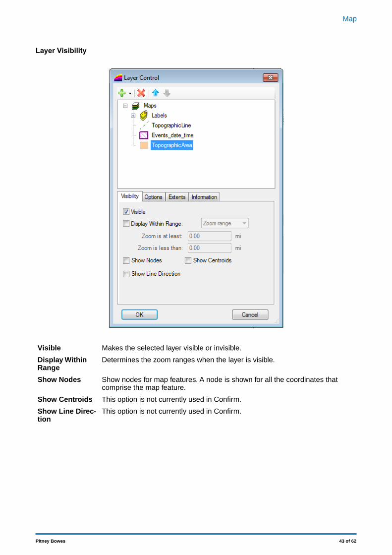
Layer Visibility
Makes the selected layer visible or invisible.Visible
Determines the zoom ranges when the layer is visible.Display WithinRange
Show nodes for map features. A node is shown for all the coordinates thatcomprise the map feature.
Show Nodes
This option is not currently used in Confirm.Show Centroids
This option is not currently used in Confirm.Show Line Direc-tion
43 of 62Pitney Bowes
Map
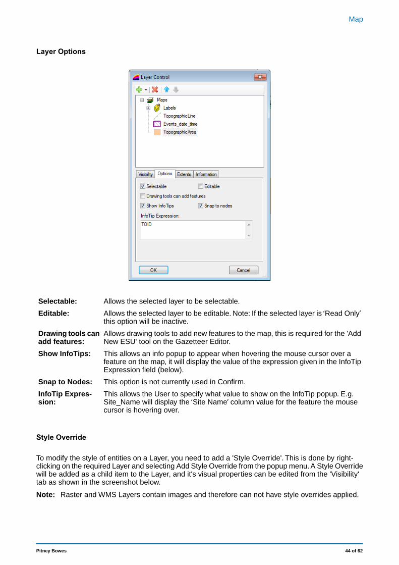
Layer Options
Allows the selected layer to be selectable.Selectable:
Allows the selected layer to be editable. Note: If the selected layer is ‘Read Only’this option will be inactive.
Editable:
Allows drawing tools to add new features to the map, this is required for the 'AddNew ESU' tool on the Gazetteer Editor.
Drawing tools canadd features:
This allows an info popup to appear when hovering the mouse cursor over afeature on the map, it will display the value of the expression given in the InfoTipExpression field (below).
Show InfoTips:
This option is not currently used in Confirm.Snap to Nodes:
This allows the User to specify what value to show on the InfoTip popup. E.g.Site_Name will display the ‘Site Name’ column value for the feature the mousecursor is hovering over.
InfoTip Expres-sion:
Style Override
To modify the style of entities on a Layer, you need to add a 'Style Override'. This is done by right-clicking on the required Layer and selecting Add Style Override from the popup menu. A Style Overridewill be added as a child item to the Layer, and it's visual properties can be edited from the 'Visibility'tab as shown in the screenshot below.
Raster and WMS Layers contain images and therefore can not have style overrides applied.Note:
44 of 62Pitney Bowes
Map
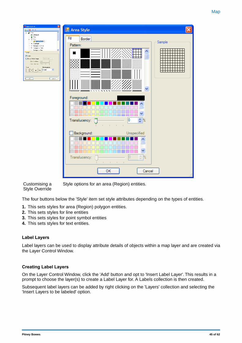
Style options for an area (Region) entities.Customising aStyle Override
The four buttons below the 'Style' item set style attributes depending on the types of entities.
1. This sets styles for area (Region) polygon entities.2. This sets styles for line entities3. This sets styles for point symbol entities4. This sets styles for text entities.
Label Layers
Label layers can be used to display attribute details of objects within a map layer and are created viathe Layer Control Window.
Creating Label LayersOn the Layer Control Window, click the 'Add' button and opt to 'Insert Label Layer'. This results in aprompt to choose the layer(s) to create a Label Layer for. A Labels collection is then created.
Subsequent label layers can be added by right clicking on the 'Layers' collection and selecting the'Insert Layers to be labeled' option.
45 of 62Pitney Bowes
Map
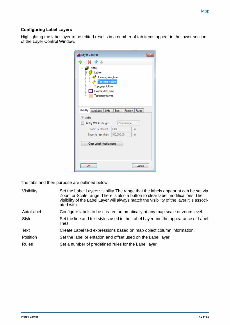
Configuring Label LayersHighlighting the label layer to be edited results in a number of tab items appear in the lower sectionof the Layer Control Window.
The tabs and their purpose are outlined below:
Set the Label Layers visibility. The range that the labels appear at can be set viaZoom or Scale range. There is also a button to clear label modifications. The
Visibility
visibility of the Label Layer will always match the visibility of the layer it is associ-ated with.
Configure labels to be created automatically at any map scale or zoom level.AutoLabel
Set the line and text styles used in the Label Layer and the appearance of Labellines.
Style
Create Label text expressions based on map object column information.Text
Set the label orientation and offset used on the Label layer.Position
Set a number of predefined rules for the Label layer.Rules
46 of 62Pitney Bowes
Map
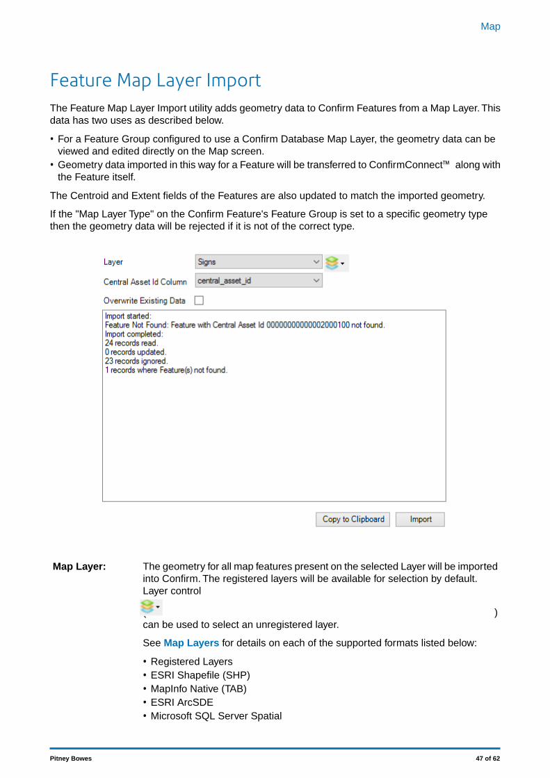
Feature Map Layer ImportThe Feature Map Layer Import utility adds geometry data to Confirm Features from a Map Layer. Thisdata has two uses as described below.
• For a Feature Group configured to use a Confirm Database Map Layer, the geometry data can beviewed and edited directly on the Map screen.
• Geometry data imported in this way for a Feature will be transferred to ConfirmConnect™ along withthe Feature itself.
The Centroid and Extent fields of the Features are also updated to match the imported geometry.
If the "Map Layer Type" on the Confirm Feature's Feature Group is set to a specific geometry typethen the geometry data will be rejected if it is not of the correct type.
The geometry for all map features present on the selected Layer will be importedinto Confirm. The registered layers will be available for selection by default.
Map Layer:
Layer control
( )can be used to select an unregistered layer.
See Map Layers for details on each of the supported formats listed below:
• Registered Layers• ESRI Shapefile (SHP)• MapInfo Native (TAB)• ESRI ArcSDE• Microsoft SQL Server Spatial
47 of 62Pitney Bowes
Map

• Oracle Spatial
This is the column used to identify map features as Features in Confirm.Central Asset IdColumn:
When ticked existing geometry stored in Confirm will be overwritten. When notticked only Features in Confirm that have no current geometry assigned to themwill be updated.
Overwrite Exist-ing Data:
The 'Progress' window displays information for any issues and summary for a run. 'Copy To Clipboard'can be used to copy this information to any text editor after the run is complete.
If there is any additional spatial data like M (measure) and Z (elevation) values in the MapLayer, then those need to be removed before importing the Map Layer.
Note:
48 of 62Pitney Bowes
Map
Update Entity GeometryThe Update Entity Geometry utility copies the current geometry information for Jobs and Defects andstore it in a spatial column in Database.
Running the utility without adding the date will update all Jobs / Defects and will take sometime ( multiple hours) to complete.
Note:
49 of 62Pitney Bowes
Map
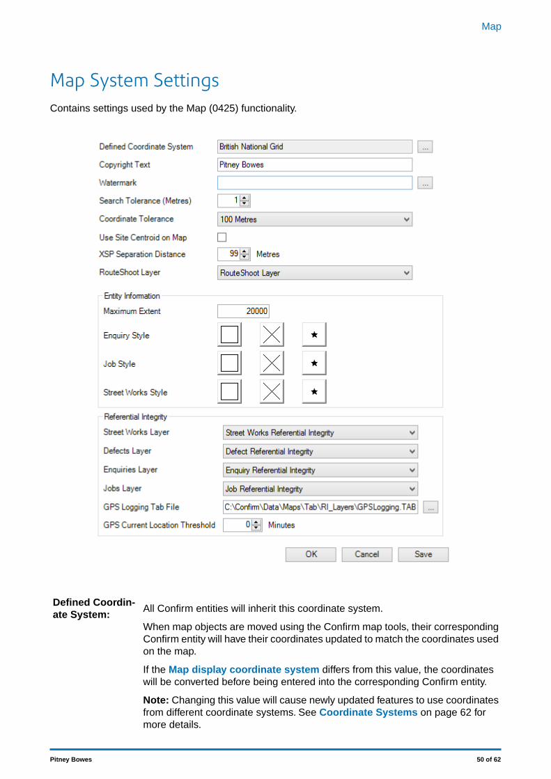
Map System SettingsContains settings used by the Map (0425) functionality.
All Confirm entities will inherit this coordinate system.Defined Coordin-ate System:
When map objects are moved using the Confirm map tools, their correspondingConfirm entity will have their coordinates updated to match the coordinates usedon the map.
If the Map display coordinate system differs from this value, the coordinateswill be converted before being entered into the corresponding Confirm entity.
Note: Changing this value will cause newly updated features to use coordinatesfrom different coordinate systems. See Coordinate Systems on page 62 formore details.
50 of 62Pitney Bowes
Map
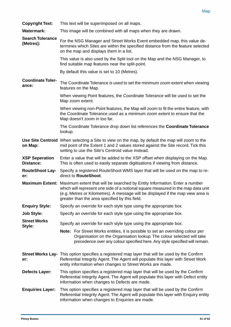
This text will be superimposed on all maps.Copyright Text:
This image will be combined with all maps when they are drawn.Watermark:
For the NSG Manager and Street Works Event embedded map, this value de-termines which Sites are within the specified distance from the feature selectedon the map and displays them in a list.
Search Tolerance(Metres):
This value is also used by the Split tool on the Map and the NSG Manager, tofind suitable map features near the split-point.
By default this value is set to 10 (Metres).
The Coordinate Tolerance is used to set the minimum zoom extent when viewingfeatures on the Map.
Coordinate Toler-ance:
When viewing Point features, the Coordinate Tolerance will be used to set theMap zoom extent.
When viewing non-Point features, the Map will zoom to fit the entire feature, withthe Coordinate Tolerance used as a minimum zoom extent to ensure that theMap doesn't zoom in too far.
The Coordinate Tolerance drop down list references the Coordinate Tolerancelookup.
When selecting a Site to view on the map, by default the map will zoom to themid point of the Extent 1 and 2 values stored against the Site record. Tick thissetting to use the Site's Centroid value instead.
Use Site Centroidon Map:
Enter a value that will be added to the XSP offset when displaying on the Map.This is often used to easily separate digitisations if viewing from distance.
XSP SeperationDistance:
Specify a registered RouteShoot WMS layer that will be used on the map to re-direct to RouteShoot.
RouteShoot Lay-er:
Maximum extent that will be searched by Entity Information. Enter a numberwhich will represent one side of a notional square measured in the map data unit
Maximum Extent:
(e.g. Metres or Kilometres). A message will be displayed if the map view area isgreater than the area specified by this field.
Specify an override for each style type using the appropriate box.Enquiry Style:
Specify an override for each style type using the appropriate box.Job Style:
Specify an override for each style type using the appropriate box.Street WorksStyle:
For Street Works entities, it is possible to set an overriding colour perOrganisation on the Organisation lookup. The colour selected will takeprecedence over any colour specified here. Any style specified will remain.
Note:
This option specifies a registered map layer that will be used by the ConfirmReferential Integrity Agent. The Agent will populate this layer with Street Workentity information when changes to Street Works are made.
Street Works Lay-er:
This option specifies a registered map layer that will be used by the ConfirmReferential Integrity Agent. The Agent will populate this layer with Defect entityinformation when changes to Defects are made.
Defects Layer:
This option specifies a registered map layer that will be used by the ConfirmReferential Integrity Agent. The Agent will populate this layer with Enquiry entityinformation when changes to Enquiries are made.
Enquiries Layer:
51 of 62Pitney Bowes
Map

This option specifies a registered map layer that will be used by the ConfirmReferential Integrity Agent. The Agent will populate this layer with Job entity in-formation when changes to Jobs are made.
Jobs Layer:
This option specifies a MapInfo Pro compatible TAB file that will be used by theConfirm Referential Integrity Agent.The Agent will populate this layer with Action
GPS Logging TabFile:
Officers current GPS location information when new updates are received viathe Confirm Connector.
The GPS file will be created when the Referential Integrity Agent runs.Note:
This setting governs how long to wait (in minutes) before removing Action Officercurrent location markers on the Map. When the stored date and time of the co-
GPS Current Loc-ation Threshold
ordinate record has gone over the threshold value it will be removed from theMap when the Referential Integrity Agent next runs. This threshold will also beused when viewing the Action Officer lookup and will cause the Distance valueto be set to 'Lapsed' if it has passed the threshold.
52 of 62Pitney Bowes
Map
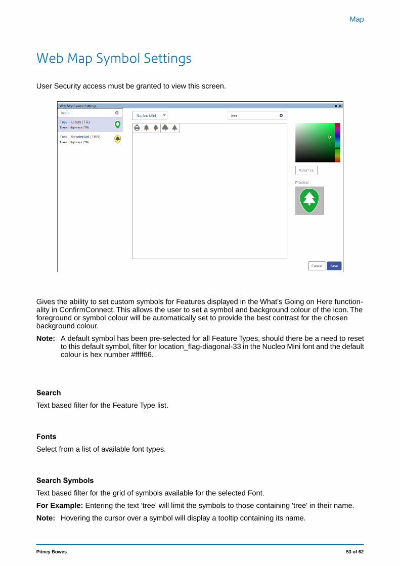
Web Map Symbol Settings
User Security access must be granted to view this screen.
Gives the ability to set custom symbols for Features displayed in the What's Going on Here function-ality in ConfirmConnect. This allows the user to set a symbol and background colour of the icon. Theforeground or symbol colour will be automatically set to provide the best contrast for the chosenbackground colour.
A default symbol has been pre-selected for all Feature Types, should there be a need to resetto this default symbol, filter for location_flag-diagonal-33 in the Nucleo Mini font and the defaultcolour is hex number #ffff66.
Note:
SearchText based filter for the Feature Type list.
FontsSelect from a list of available font types.
Search SymbolsText based filter for the grid of symbols available for the selected Font.
For Example: Entering the text 'tree' will limit the symbols to those containing 'tree' in their name.
Hovering the cursor over a symbol will display a tooltip containing its name.Note:
53 of 62Pitney Bowes
Map
Colour PickerSelect the desired colour. The text field beneath the colour picker allows the entry of a hex numbershould a specific colour be required.
Preview:Displays the chosen Symbol for the currently selected Feature Type.
54 of 62Pitney Bowes
Map
Web Map Layer SettingsThis screen provides the ability to configure background map layers for ConfirmConnect and Confirm-Workzone, which can be used to replace the default Bing maps.
The screen removes the need to request SQL from Pitney Bowes to apply these settings. Itwill ensure that the entered text is within the database limit of 4000 characters, but will notcurrently validate that the content corresponds to a valid settings.js file.
Note:
This will apply to all users of ConfirmConnect who do not currently have a set-tings.js file loaded on their device.
ConfirmConnectMap Layer Settings
This will apply to all users of ConfirmWorkzone.ConfirmWorkzoneMap Layer Settings
55 of 62Pitney Bowes
Map
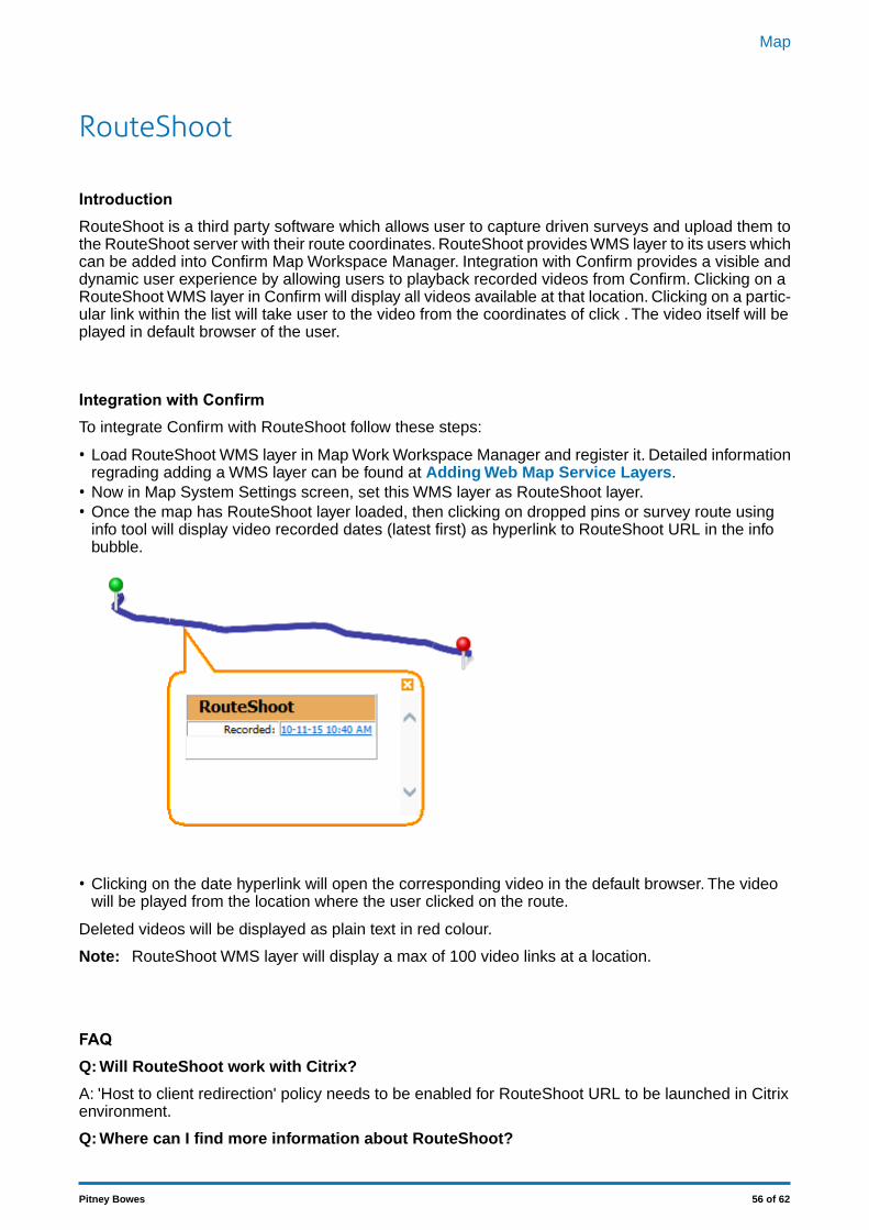
RouteShoot
IntroductionRouteShoot is a third party software which allows user to capture driven surveys and upload them tothe RouteShoot server with their route coordinates. RouteShoot provides WMS layer to its users whichcan be added into Confirm Map Workspace Manager. Integration with Confirm provides a visible anddynamic user experience by allowing users to playback recorded videos from Confirm. Clicking on aRouteShoot WMS layer in Confirm will display all videos available at that location. Clicking on a partic-ular link within the list will take user to the video from the coordinates of click . The video itself will beplayed in default browser of the user.
Integration with ConfirmTo integrate Confirm with RouteShoot follow these steps:
• Load RouteShoot WMS layer in Map Work Workspace Manager and register it. Detailed informationregrading adding a WMS layer can be found at Adding Web Map Service Layers.
• Now in Map System Settings screen, set this WMS layer as RouteShoot layer.• Once the map has RouteShoot layer loaded, then clicking on dropped pins or survey route using
info tool will display video recorded dates (latest first) as hyperlink to RouteShoot URL in the infobubble.
• Clicking on the date hyperlink will open the corresponding video in the default browser. The videowill be played from the location where the user clicked on the route.
Deleted videos will be displayed as plain text in red colour.
RouteShoot WMS layer will display a max of 100 video links at a location.Note:
FAQQ: Will RouteShoot work with Citrix?
A: 'Host to client redirection' policy needs to be enabled for RouteShoot URL to be launched in Citrixenvironment.
Q: Where can I find more information about RouteShoot?
56 of 62Pitney Bowes
Map

A: Detailed information about RouteShoot can be found at http://www.routeshoot.com.
Q: Where can I find the Licensing information for RouteShoot?
A:The Licencing information can be found at http://www.routeshoot.com/routeshoot/How-it-works/Plans
Q: I noticed delay in loading RouteShoot WMS layer, can this be improved?
A: Please contact RouteShoot support.
57 of 62Pitney Bowes
Map
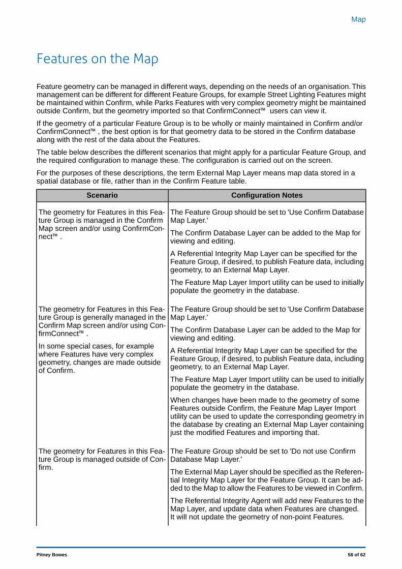
Features on the Map
Feature geometry can be managed in different ways, depending on the needs of an organisation.Thismanagement can be different for different Feature Groups, for example Street Lighting Features mightbe maintained within Confirm, while Parks Features with very complex geometry might be maintainedoutside Confirm, but the geometry imported so that ConfirmConnect™ users can view it.
If the geometry of a particular Feature Group is to be wholly or mainly maintained in Confirm and/orConfirmConnect™, the best option is for that geometry data to be stored in the Confirm databasealong with the rest of the data about the Features.
The table below describes the different scenarios that might apply for a particular Feature Group, andthe required configuration to manage these. The configuration is carried out on the screen.
For the purposes of these descriptions, the term External Map Layer means map data stored in aspatial database or file, rather than in the Confirm Feature table.
Configuration NotesScenario
The Feature Group should be set to 'Use Confirm DatabaseMap Layer.'
The geometry for Features in this Fea-ture Group is managed in the ConfirmMap screen and/or using ConfirmCon-nect™. The Confirm Database Layer can be added to the Map for
viewing and editing.
A Referential Integrity Map Layer can be specified for theFeature Group, if desired, to publish Feature data, includinggeometry, to an External Map Layer.
The Feature Map Layer Import utility can be used to initiallypopulate the geometry in the database.
The Feature Group should be set to 'Use Confirm DatabaseMap Layer.'
The geometry for Features in this Fea-ture Group is generally managed in theConfirm Map screen and/or using Con-firmConnect™. The Confirm Database Layer can be added to the Map for
viewing and editing.In some special cases, for examplewhere Features have very complex A Referential Integrity Map Layer can be specified for the
Feature Group, if desired, to publish Feature data, includinggeometry, to an External Map Layer.
geometry, changes are made outsideof Confirm.
The Feature Map Layer Import utility can be used to initiallypopulate the geometry in the database.
When changes have been made to the geometry of someFeatures outside Confirm, the Feature Map Layer Importutility can be used to update the corresponding geometry inthe database by creating an External Map Layer containingjust the modified Features and importing that.
The Feature Group should be set to 'Do not use ConfirmDatabase Map Layer.'
The geometry for Features in this Fea-ture Group is managed outside of Con-firm.
The External Map Layer should be specified as the Referen-tial Integrity Map Layer for the Feature Group. It can be ad-ded to the Map to allow the Features to be viewed in Confirm.
The Referential Integrity Agent will add new Features to theMap Layer, and update data when Features are changed.It will not update the geometry of non-point Features.
58 of 62Pitney Bowes
Map
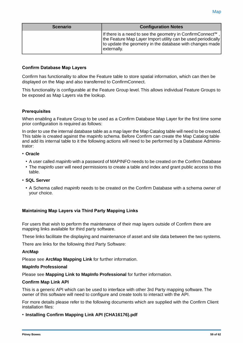
Configuration NotesScenario
If there is a need to see the geometry in ConfirmConnect™,the Feature Map Layer Import utility can be used periodicallyto update the geometry in the database with changes madeexternally.
Confirm Database Map Layers
Confirm has functionality to allow the Feature table to store spatial information, which can then bedisplayed on the Map and also transferred to ConfirmConnect.
This functionality is configurable at the Feature Group level. This allows individual Feature Groups tobe exposed as Map Layers via the lookup.
PrerequisitesWhen enabling a Feature Group to be used as a Confirm Database Map Layer for the first time someprior configuration is required as follows:
In order to use the internal database table as a map layer the Map Catalog table will need to be created.This table is created against the mapinfo schema. Before Confirm can create the Map Catalog tableand add its internal table to it the following actions will need to be performed by a Database Adminis-trator:
• Oracle
• A user called mapinfo with a password of MAPINFO needs to be created on the Confirm Database• The mapinfo user will need permissions to create a table and index and grant public access to this
table.
• SQL Server
• A Schema called mapinfo needs to be created on the Confirm Database with a schema owner ofyour choice.
Maintaining Map Layers via Third Party Mapping Links
For users that wish to perform the maintenance of their map layers outside of Confirm there aremapping links available for third party software.
These links facilitate the displaying and maintenance of asset and site data between the two systems.
There are links for the following third Party Software:
ArcMap
Please see ArcMap Mapping Link for further information.
MapInfo Professional
Please see Mapping Link to MapInfo Professional for further information.
Confirm Map Link API
This is a generic API which can be used to interface with other 3rd Party mapping software. Theowner of this software will need to configure and create tools to interact with the API.
For more details please refer to the following documents which are supplied with the Confirm Clientinstallation files:
• Installing Confirm Mapping Link API (CHA16176).pdf
59 of 62Pitney Bowes
Map
• Confirm Mapping Link API Specification (CHA16167).pdf
ArcIMS
This mapping link is due to be phased out with the arrival of ArcGis 10.1 according to ESRI's website.
Note: To use any of the above mapping links you will need to have Confirm Module 0400 MappingInterface activated.
60 of 62Pitney Bowes
Map
FAQThis section covers some of the commonly asked questions in the Map module.
Editing SDE Layers
• ArcSDE 9.3
Layers must be 'Registered as Versioned'
• ArcSDE 10.0
Layers must not be 'Registered as Versioned'
Editing Oracle Spatial Layers
Adding a object to the Map requires the Primary Key for each object to be inserted into the databasetable. This is not done automatically by Confirm. in order to do this a Sequence and Trigger need tobe created.
Creating an Oracle Sequence and Trigger on Oracle 11g and 12cThe example SQL below shows how a Trigger can be created:-
CREATE SEQUENCE SEQUENCE_NAMESTART WITH MAX+1INCREMENT BY 1;CREATE OR REPLACE TRIGGER SCHEMA.TRIGGER_NAMEBEFORE INSERTON SCHEMA.TABLE_NAMEREFERENCING NEW AS NEW OLD AS OLDFOR EACH ROWBEGIN:NEW.PRIMARYINDEXNAME := SEQUENCE_NAME.nextval ;END;
MAX+1 needs to be replaced with the value returned by SELECT MAX(PRIMARYINDEXNAME)FROM SCHEMA.TABLE_NAME;
Replace all bold entries with values applicable to the database table where creation of new objectsis required.
Creating an Oracle Sequence and Trigger on Oracle 10gCREATE SEQUENCE SEQUENCE_NAMESTART WITH MAX+1INCREMENT BY 1;CREATE OR REPLACE TRIGGER SCHEMA.TRIGGER_NAMEBEFORE INSERTON SCHEMA.TABLE_NAMEFOR EACH ROWBEGINSELECT SEQUENCE_NAME.nextval INTO :NEW.PRIMARYINDEXNAME FROM dual;END;
MAX+1 needs to be replaced with the value returned by SELECT MAX(PRIMARYINDEXNAME)FROM SCHEMA.TABLE_NAME;
61 of 62Pitney Bowes
Map
Replace all bold entries with values applicable to the database table where creation of new objectsis required.
Coordinate Systems
Coordinate Systems are the mathematical reference schemes used to specify locations on the surfaceof the Earth. There are many coordinate systems in existence, usually they are specific to particularcountries.
Adding LayersWhen adding Layers to the map, it is important to consider how layers interact with the Map CoordinateSystem and Defined Coordinate System.
There are a few rules to bear in mind:
• When the first Layer is added, the Map will adopt that first Layer's Coordinate System as the 'MapCoordinate System' that the whole map will operate in.
• If there is already a Layer present then adding new Layers will not change the 'Map CoordinateSystem'.
• The 'Map Coordinate System' can be changed from the 'Coordinate System' tab on the 'Layer Control'at any time. However, if the 'Map Coordinate System' is changed using this option before addingany Layers, then the first layer added will change the current 'Map Coordinate System' setting.
• If the 'Defined Coordinate System' has not been set (on the Map System Settings on page 50),then all Layers added must have the same coordinate system to avoid ambiguities. General goodpractice is to set the 'Defined Coordinate System' first before attempting to configure the Map Layers.
• The 'Defined Coordinate System' is not necessarily the same as the 'Map Coordinate System'. The'Defined Coordinate System' is the format of coordinates stored in the Confirm database. The 'MapCoordinate System' is the system used to draw the map on the screen. Confirm will automaticallyconvert when storing coordinates in the database.
• Adding any image layer (Raster, WMS etc) will force the map to change projection into that layersrendered coordinate system.
Adding Raster Layers
When adding Raster layers to the Map e.g. WMS Layers, the required MapXtreme dll files need to beavailable by stating their location in the System Path Variable.
If the variable is not set an error can occur when adding the layer to a workspace.
The path for the dll files needs to be added to the system path variable as follows:
32 Bit Machines
C:\Program Files\Common Files\MapInfo\MapXtreme\7.2.0\RasterGridHandlers
64 Bit Machines
C:\Program Files (x86)\Common Files\MapInfo\MapXtreme\7.2.0\RasterGridHandlers
62 of 62Pitney Bowes
Map


![Audio General · as shown on the right. Click [Finish]. This completes the software installation. Your computer will automatically restart. (1) To confirm that the software has been](https://img.pdfslide.us/doc/110x75/601bdf5f8e88084e166ad8d8/audio-general-as-shown-on-the-right-click-finish-this-completes-the-software.jpg)