Embed Size (px)
Citation preview

Configuration Guide for SAP PLM 7 to support Product Structure Management dynamic Viewing (DMU) based on Visual Enterprise Instance Planner (VIP) and geometrical Instance Management.

www.sap.com
TABLE OF CONTENTS
1. SAP ERP ENHANCEMENT - (EHP) AND SUPPORT PACKAGES (SP) PREREQUISITES ........... 3
2. SUPORTED CAD SYSTEMS ............................................................................................................. 4
3. SWITCH FRAMEWORK (SFW5) ....................................................................................................... 5
3.1. ENTERPRISE EXTENSION................................................................................................................ 5
3.1.1. ENTERPRISE BUSINESS FUNCTIONS ............................................................................................ 5
4. DOCUMENT MANAGEMENT SYSTEM (DMS) CUSTOMIZING ....................................................... 6
4.1. CUSTOMIZING OF DOCUMENT TYPES AND APPLICATION TYPES ........................................... 6
4.2. DEFINE DATA CARRIER ................................................................................................................. 14
4.3. DEFINE WORKSTATION APPLICATION ....................................................................................... 16
5. VISUAL ENTERPRISE CUSTOMIZATION ...................................................................................... 21
5.1. VISUAL ENTERPRISE VIEWER CLIENT INSTALLATION ............................................................ 21
5.1.1. DEFINE SEARCH SEQUENCE FOR VIEWABLE FILES ................................................................ 21
5.1.2. READ_DMS_VEG_VSS - READ SEARCH SEQUENCE ................................................................ 22
5.2. VISUAL ENTERPRISE STRUCTURE MANAGER CLIENT INSTALLATION ................................ 23
5.2.1. CLIENT INSTALLATION .................................................................................................................. 23
5.2.2. DEFINE SEARCH SEQUENCE FOR VIEWABLE FILES ................................................................ 23
6. VISUAL ENTERPRISE GENERATOR (VEG) .................................................................................. 24
6.1. VEG INSTALLATION AND CONFIGURATION ............................................................................... 24
6.2. CONNECT ERP WITH VEG ............................................................................................................. 24
6.3. VEG CUSTOMISING ........................................................................................................................ 26
6.4. ERP CUSTOMISING, VEG CONVERSION TRIGGER .................................................................... 28
7. PRUDUCT STRUCTURE MANAGEMENT ...................................................................................... 31
7.1. PSM STANDARD CUSTOMIZING ................................................................................................... 31
7.1.1. PREFERENCE DOCUMENT ASSIGNMENT - STANDARD CUSTOMIZING- ............................... 31
7.1.2. PSM MAINTENANCE OF RELEVANT NODE TYPES (/PLMI/PPE_VIP_ND) ................................ 31
7.1.3. PRODUCT VIEW -USER SETTINGS DEFINE PRIORITY FOR PSM STRUCTURE ...................... 32

3
1. SAP ERP ENHANCEMENT - (EHP) AND SUPPORT PACKAGES (SP) PREREQUISITES
The Configuration Guide described functionalities are available from SAP ERP EHP 6 SP15, SAP ERP EHP
7 SP08, EHP8 SP01 and higher.
The Documents Management System, CAD – Integration and Visual Enterprise Generator (VEG) set up is
described based on the SolidWorks SAP Integration. For other CAD Products like ProE, CATIA or Siemens
NX additional Customizing is needed, which is not described in this Guide.

4
2. SUPORTED CAD SYSTEMS
The pre-requisite for these solutions is the ability to create tagged viewable representation of the 3D CAD
originals.
In the scenario where the CAD originals are stored in DMS via a CAD partner integration is supported:
Solidworks
Catia v5
Unigraphics NX
Creo (ProE)
SolidEdge
Inventor
In addition to the formats listed above in the scenario where the CAD files are stored in a competitors PDM
system (Teamcentre / Wildfire etc.) we support all the above formats plus PLMXML + JT
This Configurations Guide is based on the Solidworks Integration, this means most Customizing entries a
referred to the usage of Solidworks.

5
3. SWITCH FRAMEWORK (SFW5)
3.1. ENTERPRISE EXTENSION
EA_PLM PLM Extension
3.1.1. ENTERPRISE BUSINESS FUNCTIONS
/PLMU/COEX_IPPE_BOM PLM Coexistence IPPE BOM
/PLMU/GSS_E2M Synchronization of EBOM with MBOM
/PLMU/WEB_UI PLM Web User Interface
/PLMU/WEB_UI_2 PLM Web User Interface 2
/PLMU/WEB_UI_3 PLM Web User Interface 3 (Reversible)
/PLMU/IPPE_INT PLM IPPE Integration
/PLMU/IPPE_INT_2 PLM, Product Structure and Assembly Management
PLM_VIP_1 PLM, Visual Instance Planner
Dependencies:
PLMU/IPPE_INT_3 PLM, Product Structure and Assembly Management 3 (Reversible)
Dependencies:
/PLMU/IPPE_INT_4 PLM, Product Structure and Assembly Management 4 (Reversible)
Dependencies:

6
4. DOCUMENT MANAGEMENT SYSTEM (DMS) CUSTOMIZING
All DMS settings are for the SolidWorks CAD direct Integration into SAP. The Application and Document
Types are for SolidWorks-Assemblies SWA, SolidWorks-Parts SWP, SolidWorks-Drawings SWD and for
SAP Visual Enterprise 3D visualization / VED.
4.1. CUSTOMIZING OF DOCUMENT TYPES AND APPLICATION TYPES
Use
In this activity, you define document type SWA, SWP, SWD and VED for creating documents.
Prerequisites
A number range has been defined.
Recommendation:
SAP Document Management stores the document info records, i.e., the metadata, in the SAP system.
The document info records contain links to the original files. These original files should be stored on an
SAP Content Server, i.e. a separate server.
If an SAP Content Server is not available, storage category DMS_C1_ST can be used. Using this
category will save the original files in the SAP database. This is useful for testing but not recommended
for a production environment.
Please refer section 1.3 for installation and configuration of the Content Server

7
Procedure
1. Access the activity using one of the following navigation options:
Customizing Menu Cross-Application Components → Document Management →
Control Data → Define document types
Transaction Code DC10
2. On the Change View Define Document Types: Overview screen, choose the New entries pushbutton.
3. On the New Entries: Details of Added Entries screen, enter the following values:

8
Field Name Description User Action and
Values Comment
Document Type SWA
Document Type
description SolidWorks Assembly
Use KPro <Select by
ticking>
Use ACM <Select by
ticking>
Display Object
Links
<Select by
ticking>
Version
Assignment
<Select by
ticking>
Change Docs <Select by
ticking> Optional
Internal Number
Range 02
Select Number
Ranges to define your
own number ranges.
External number
range 04
Select any internal
range 01 or 05 based
on business use case
if needed
Number exit MCDOKZNR Select Default to
generate this entry.
Vers. No. Incr. 1
Select "1" if you want
versions to start with
"00" instead of "01"
Default Appl. SWA or ””
The application type
and workstation
application would be
created in follow up
steps. Hence maintain
the values only once
these are created.
Keep blank value for
now.
Dis. WS applic. SWA or “”
Hierarchy indicator -
Document Status -
Document
Description -
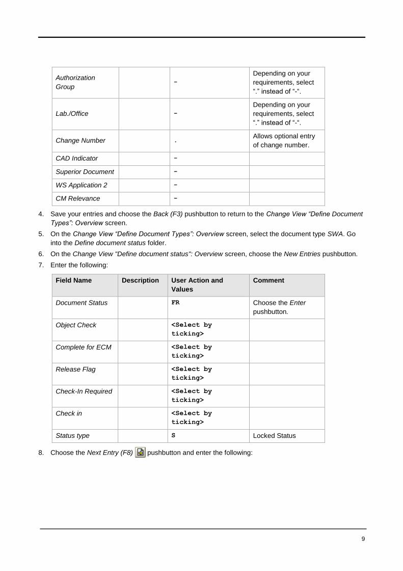
9
Authorization
Group -
Depending on your
requirements, select
“.” instead of “-“.
Lab./Office -
Depending on your
requirements, select
“.” instead of “-“.
Change Number . Allows optional entry
of change number.
CAD Indicator -
Superior Document -
WS Application 2 -
CM Relevance -
4. Save your entries and choose the Back (F3) pushbutton to return to the Change View “Define Document
Types”: Overview screen.
5. On the Change View “Define Document Types”: Overview screen, select the document type SWA. Go
into the Define document status folder.
6. On the Change View "Define document status": Overview screen, choose the New Entries pushbutton.
7. Enter the following:
Field Name Description User Action and
Values
Comment
Document Status FR Choose the Enter
pushbutton.
Object Check <Select by
ticking>
Complete for ECM <Select by
ticking>
Release Flag <Select by
ticking>
Check-In Required <Select by
ticking>
Check in <Select by
ticking>
Status type S Locked Status
8. Choose the Next Entry (F8) pushbutton and enter the following:

10
Field Name Description User Action and
Values
Comment
Document
Status
IA Choose the Enter
pushbutton.
Object Check <Select by
ticking>
Check in <Select by
ticking>
Status type I Initial Status
9. Save your entries and return to the "Define document status": Overview screen (you may need to choose
the Back (F3) pushbutton twice).
10. Choose the Select All (F7) pushbutton to select both newly created statuses, and then choose the
Details (Ctrl-Shift-F2) pushbutton to change the statuses.
11. For document status FR, enter IA in field Prev. 1, and then choose the Next Entry (F8) pushbutton.
12. For document Status IA, enter FR in field Prev. 1.
This will allow you to switch back from status FR (released) to status IA (in process). You may
omit this step if you would prefer not to allow changes to released documents. In this case, users
will have to create a new version whenever they need to make changes to a document that has
already been released.
13. More document statuses can be created as per business requirements.
14. Save your entries and return to the Change View “Define Document Types”: Overview screen (you may
need to choose the Back (F3) pushbutton twice). You have created the status network for the document
type.
15. On the Change View “Define Document Types”: Overview screen, select document type SWA. Go to the
folder Define object links.
16. Choose the New Entries button and enter the following:

11
Field Name Description User Action and
Values
Comment
Document
Type
SWA
Object MARA Choose the Enter
pushbutton.
Dynpro No. 201
When New
Version
Depending on your
requirements
Create
Document
Depending on your
requirements
Document
Version
Depending on your
requirements
17. Choose the Next Entry (F8) pushbutton and enter the following:
Field Name Description User Action and
Values
Comment
Document
Type
SWA
Object DRAW Choose the Enter
pushbutton.
Dynpro No. 202
When New
Version
Depending on your
requirements
Create
Document
Depending on your
requirements
Document
Version
Depending on your
requirements

12
18. Choose the Next Entry (F8) pushbutton and enter the following:
Field Name Description User Action and
Values
Comment
Document
Type
SWA
Object PNODID
Dynpro No. 500
When New
Version
Depending on your
requirements
Create
Document
Depending on your
requirements
Document
Version
Depending on your
requirements
19. Choose the Next Entry (F8) pushbutton and enter the following:
Field Name Description User Action and
Values
Comment
Document
Type
SWA
Object POSVID
Dynpro No. 500
When New
Version
Depending on your
requirements
Create
Document
Depending on your
requirements
Document
Version
Depending on your
requirements
20. Save your entries and return to the Change View “Define Document Types”: Overview screen (you may
need to choose the Back (F3) pushbutton twice). You have set up four possible object links for document
type SWA. Save your entries and exit the transaction (you will need to choose the Back (F3) pushbutton

13
several times). You have created object links to the material master, document info record, PPE Node
and PPE Variant.
21. Similarly create document types for SWP, SWD and VED. (steps 3 to 20) Please note for document type
SWP, SWD and VED, following changes should be done and remaining should be same like above
mentioned steps.
Field Name Description User Action and
Values Comment
Document Type SWP
Document Type
description SolidWorks Part
Default Appl. SWP or ””
The application type
and workstation
application would be
created in follow up
steps. Hence maintain
the values only once
these are created.
Keep blank value for
now.
Dis. WS applic. SWP or “”
Field Name Description User Action and
Values Comment
Document Type SWD
Document Type
description SolidWorks Drawing
Default Appl. SWD or ””
The application type
and workstation
application would be
created in follow up
steps. Hence maintain
the values only once
these are created.
Keep blank value for
now.
Dis. WS applic. SWD or “”

14
Field Name Description User Action and
Values Comment
Document Type VED
Document Type
description VEG 3D Visuals
Default Appl. “” Keep the value blank
Dis. WS applic. “” Keep the value blank
22. Save you entries
Result
The document types SWA, SWP, SWD and VED used has been defined, and a basic status network and
some object links have been set up.
4.2. DEFINE DATA CARRIER
Use
In this activity, you define the data carrier type PC.
Procedure
Access the next activity using one of the following navigation options:
Customizing Menu Customizing → Cross-Application Components → Document
Management → General Data → Define Data Carrier
Transaction Code SPRO
1. Choose the Enter pushbutton to confirm the information message Caution: The table is cross-client.
2. On the Change View “Define data carrier type “archive”: Overview screen, double-click the folder Define
data carrier type “server, front end” and choose the New Entries pushbutton.
3. Enter the following:

15
Field Name Description User Action and
Values
Comment
Type Data carrier
type
PC
Description PC with MS Windows
Operating System
Path If left empty, temporary
files will be placed into the
standard Windows folder
for temporary files (Local
Settings\Temp) or the path
entered in WinGUI –
Options – Local Data is
used. Alternatively, you
may enter any path here,
e.g. c:\temp or a network
drive.
Online Set indicator
4. Select your entry and choose the Define servers and files or folders pushbutton. Choose the New entries
pushbutton to make a new entry containing the following values:
Field Name Description User Action and Values Comment
Data Carr. PC
Type Data carrier
type
Default
Description Personal Computer
5. Select the entry Identify frontend computers in the dialog structure. Choose the Default entry pushbutton
to make a new entry containing the following values:
Field Name Description User Action and Values Comment
FrontendComputer Default
Data carr. Type Data carrier type PC
Netw. Address DEFAULT
Description Default for local
PC
6. Double-click entry Define mount points / logical drive in the dialog structure. Choose the New entries
pushbutton to make a new entry containing the following values:
Field Name Description User Action and Values Comment
Data Carr. PC
Data carr. type PC
Prefix for
access path
C:\SAP BP
7. Save your entries.

16
Result
You have defined the data carrier.
4.3. DEFINE WORKSTATION APPLICATION
Use
In this activity, you define the settings for workstation applications.
Procedure
1. Access the activity using one of the following navigation options:
Customizing Menu Customizing → Cross-Application Components →
Document Management → General Data → Define
Workstation Application
Transaction Code DC30
2. On the Change View “Define Workstation Application”: Overview screen, choose New Entries.
3. Enter the following:
Field Name Description User Action and Values Comment
WS application Key field RH
Description SAP Product
Visualization
Archive identificatio *
File suffix for appl. File format for a
temporary file
RH
File format File format for
selection via the file
manager
*.rh,*.vds,
*.rhz,*.cgm,*.jt
MIME type application/rh
Appl. Icon @AR@
Start authorization Application can be
started immediately
Indicator set
You Cannot
rename temporary
files
Indicator determines
whether the file can be
renamed.
Indicator Set
Addnl Files Additional Files Indicator Set
4. Choose the Next Entry (F8) pushbutton and enter the following:
5. Enter the following:

17
Field Name Description User Action and Values Comment
WS application Key field SWA
Description SolidWorks Assembly
Archive identificatio *
File suffix for appl. File format for a
temporary file
SWA
File format File format for
selection via the file
manager
*.sldasm,*.asm
MIME type
Appl. Icon @CX@
Start authorization Application can be
started immediately
Indicator set
You Cannot
rename temporary
files
Indicator determines
whether the file can be
renamed.
Indicator Set
6. Choose the Next Entry (F8) pushbutton and enter the following:
7. Enter the following:
Field Name Description User Action and
Values
Comment
WS application Key field SWD
Description SolidWorks Drawing
Archive identificatio *
File suffix for appl. File format for a
temporary file
SWD
File format File format for selection
via the file manager
*.slddrw
MIME type
Appl. Icon @CX@
Start authorization Application can be
started immediately
Indicator set
You Cannot
rename temporary
files
Indicator determines
whether the file can be
renamed.
Indicator Set
8. Choose the Next Entry (F8) pushbutton and enter the following:
9. Enter the following:

18
Field Name Description User Action and
Values
Comment
WS application Key field SWP
Description SolidWorks Part
Archive identificatio *
File suffix for appl. File format for a
temporary file
SWP
File format File format for selection
via the file manager
*.sldprt ,
*.SLDPRT
MIME type
Appl. Icon @CX@
Start authorization Application can be
started immediately
Indicator set
You Cannot
rename temporary
files
Indicator determines
whether the file can be
renamed.
Indicator Set
10. Save your entries and go back to the Change View “Define workstation application”: Overview screen.
11. On the Change View “Define workstation application”: Overview screen, select the workstation
application RH and choose the Define workstation application in network pushbutton.
12. Choose the New Entries (F5) pushbutton and enter the following:s
Field Name Description User Action and Values Comment
Workstation
Application
RH Already filled
Data carr. Type PC
Application type 1
Path with prog.
Name
%VIEWER-
CONTROL%%SAPPROVIS%
13. Choose the Next Entry (F8) pushbutton and enter the following:
Field Name Description User Action and Values Comment
Workstation
Application
RH Already filled
Data carr. Type PC
Application type 2
Path with prog.
Name
%VIEWER-
CONTROL%%SAPPROVIS%
14. Save your entries and go back to the Change View “Define workstation application”: Overview screen.
15. On the Change View “Define workstation application”: Overview screen, select the workstation
application SWA and choose the Define workstation application in network pushbutton.
16. Choose the New Entries (F5) pushbutton and enter the following:

19
Field Name Description User Action and Values Comment
Workstation
Application
SWA Already filled
Data carr. Type PC
Application type 1
Path with prog.
Name
%AUTO%
17. Choose the Next Entry (F8) pushbutton and enter the following:
Field Name Description User Action and Values Comment
Workstation
Application
SWA Already filled
Data carr. Type PC
Application type 2
Path with prog.
Name
%AUTO%
18. Save your entries and go back to the Change View “Define workstation application”: Overview screen.
19. On the Change View “Define workstation application”: Overview screen, select the workstation
application SWP and choose the Define workstation application in network pushbutton.
20. Choose the Next Entry (F8) pushbutton and enter the following:
Field Name Description User Action and Values Comment
Workstation
Application
SWP Already filled
Data carr. Type PC
Application type 1
Path with prog. Name %AUTO%
21. Choose the Next Entry (F8) pushbutton and enter the following:
Field Name Description User Action and Values Comment
Workstation
Application
SWP Already filled
Data carr. Type PC
Application type 2
Path with prog. Name %AUTO%
22. Save your entries and go back to the Change View “Define workstation application”: Overview screen.
23. On the Change View “Define workstation application”: Overview screen, select the workstation
application SWD and choose the Define workstation application in network pushbutton.
24. Choose the Next Entry (F8) pushbutton and enter the following:
Field Name Description User Action and Values Comment
Workstation
Application
SWD Already filled
Data carr. Type PC
Application type 1
Path with prog. Name %AUTO%
25. Choose the Next Entry (F8) pushbutton and enter the following:

20
Field Name Description User Action and Values Comment
Workstation
Application
SWD Already filled
Data carr. Type PC
Application type 2
Path with prog. Name %AUTO%
26. Save your entries and go back to the Change View “Define workstation application”: Overview screen.
Result
You have defined the settings for workstation applications.
21
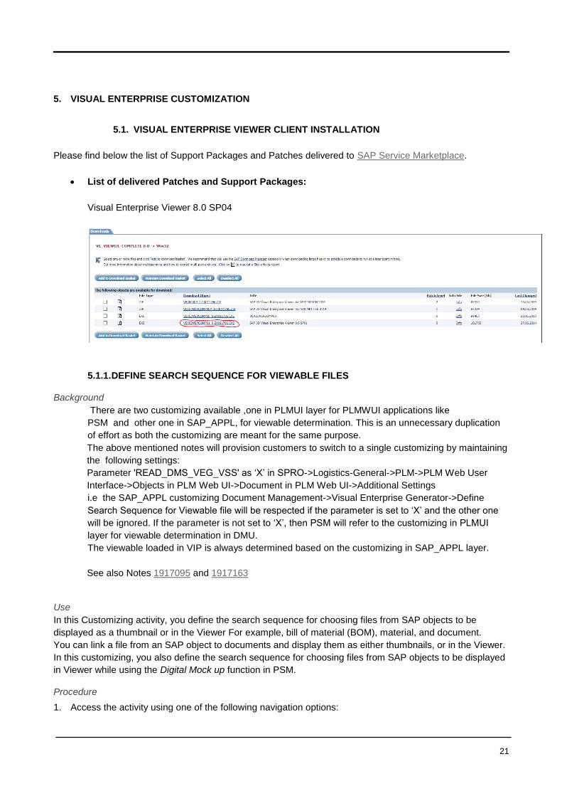
5. VISUAL ENTERPRISE CUSTOMIZATION
5.1. VISUAL ENTERPRISE VIEWER CLIENT INSTALLATION
Please find below the list of Support Packages and Patches delivered to SAP Service Marketplace.
List of delivered Patches and Support Packages:
Visual Enterprise Viewer 8.0 SP04
5.1.1. DEFINE SEARCH SEQUENCE FOR VIEWABLE FILES
Background
There are two customizing available ,one in PLMUI layer for PLMWUI applications like
PSM and other one in SAP_APPL, for viewable determination. This is an unnecessary duplication
of effort as both the customizing are meant for the same purpose.
The above mentioned notes will provision customers to switch to a single customizing by maintaining
the following settings:
Parameter 'READ_DMS_VEG_VSS' as ‘X’ in SPRO->Logistics-General->PLM->PLM Web User
Interface->Objects in PLM Web UI->Document in PLM Web UI->Additional Settings
i.e the SAP_APPL customizing Document Management->Visual Enterprise Generator->Define
Search Sequence for Viewable file will be respected if the parameter is set to ‘X’ and the other one
will be ignored. If the parameter is not set to ‘X’, then PSM will refer to the customizing in PLMUI
layer for viewable determination in DMU.
The viewable loaded in VIP is always determined based on the customizing in SAP_APPL layer.
See also Notes 1917095 and 1917163
Use
In this Customizing activity, you define the search sequence for choosing files from SAP objects to be
displayed as a thumbnail or in the Viewer For example, bill of material (BOM), material, and document.
You can link a file from an SAP object to documents and display them as either thumbnails, or in the Viewer.
In this customizing, you also define the search sequence for choosing files from SAP objects to be displayed
in Viewer while using the Digital Mock up function in PSM.
Procedure
1. Access the activity using one of the following navigation options:
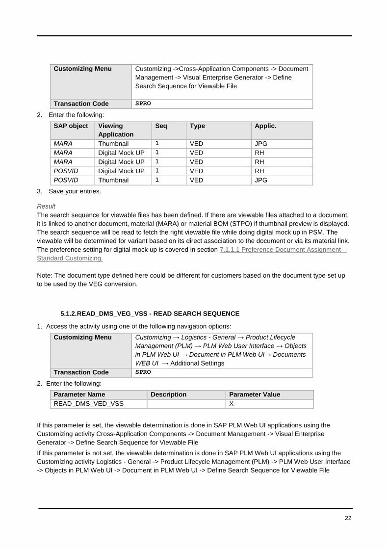
22
Customizing Menu Customizing ->Cross-Application Components -> Document
Management -> Visual Enterprise Generator -> Define
Search Sequence for Viewable File
Transaction Code SPRO
2. Enter the following:
SAP object Viewing
Application
Seq Type Applic.
MARA Thumbnail 1 VED JPG
MARA Digital Mock UP 1 VED RH
MARA Digital Mock UP 1 VED RH
POSVID Digital Mock UP 1 VED RH
POSVID Thumbnail 1 VED JPG
3. Save your entries.
Result
The search sequence for viewable files has been defined. If there are viewable files attached to a document,
it is linked to another document, material (MARA) or material BOM (STPO) if thumbnail preview is displayed.
The search sequence will be read to fetch the right viewable file while doing digital mock up in PSM. The
viewable will be determined for variant based on its direct association to the document or via its material link.
The preference setting for digital mock up is covered in section 7.1.1.1 Preference Document Assignment -
Standard Customizing.
Note: The document type defined here could be different for customers based on the document type set up
to be used by the VEG conversion.
5.1.2. READ_DMS_VEG_VSS - READ SEARCH SEQUENCE
1. Access the activity using one of the following navigation options:
Customizing Menu Customizing → Logistics - General → Product Lifecycle
Management (PLM) → PLM Web User Interface → Objects
in PLM Web UI → Document in PLM Web UI→ Documents
WEB UI → Additional Settings
Transaction Code SPRO
2. Enter the following:
Parameter Name Description Parameter Value
READ_DMS_VED_VSS X
If this parameter is set, the viewable determination is done in SAP PLM Web UI applications using the
Customizing activity Cross-Application Components -> Document Management -> Visual Enterprise
Generator -> Define Search Sequence for Viewable File
If this parameter is not set, the viewable determination is done in SAP PLM Web UI applications using the
Customizing activity Logistics - General -> Product Lifecycle Management (PLM) -> PLM Web User Interface
-> Objects in PLM Web UI -> Document in PLM Web UI -> Define Search Sequence for Viewable File

23
5.2. VISUAL ENTERPRISE STRUCTURE MANAGER CLIENT INSTALLATION
5.2.1. CLIENT INSTALLATION
DELIVERY REPORT FOR NON-ABAP PATCHES AND SUPPORT PACKAGES
Please find below the list of Support Packages and Patches delivered to SAP Service Marketplace.
List of delivered Patches and Support Packages:
Visual Enterprise Structure Manager 1.0 SP04
5.2.2. DEFINE SEARCH SEQUENCE FOR VIEWABLE FILES
Use
In this Customizing activity, you define the search sequence for determining files from source document and
target PSM structure to be displayed in Visual Instance Planner.
Procedure
4. Access the activity using one of the following navigation options:
Customizing Menu Customizing ->Cross-Application Components -> Document
Management -> Visual Enterprise Generator -> Define
Search Sequence for Viewable File
Transaction Code SPRO
5. Enter the following:
SAP object Viewing
Application
Seq Type Applic.
MARA Digital Mock UP 1 VED RH
MARA Digital Mock UP 1 VED RH
POSVID Digital Mock UP 1 VED RH
6. Save your entries.

24
Result
The search sequence for viewable files has been defined.
The viewable for VIP will be determined based on the above customizing entries.
The preference setting for digital mock up is covered in section 7.1.1.1 Preference Document Assignment -
Standard Customizing.
Note: The document type defined here could be different for customers based on the document type set up
to be used by the VEG conversion.
6. VISUAL ENTERPRISE GENERATOR (VEG)
6.1. VEG INSTALLATION AND CONFIGURATION
Use
In this activity, you install and configure SAP 3D Visual Enterprise Generator.
Prerequisites
1. SAP 3D Visual Enterprise Generator installer package
2. SAP 3D Visual Enterprise Generator SP1 installer package
3. SAP 3D Visual Enterprise Generator installation guide (found in SAP Help Portal)
Procedure
1. Follow the steps defined in the SAP 3D Visual Enterprise Generator installation guide
Result
VEG is installed and configured.
6.2. CONNECT ERP WITH VEG
Use
In this activity, you connect your ERP system with VEG.
Prerequisites
1. VEG installed and configured
2. Depending on your system, you may have to create or use an existing Customizing request
Procedure
1. Download the WebService_Template_VEG_80.zip attached to SAP Note 1694219:
https://service.sap.com/sap/support/notes/1694219
2. Open the WSDL-File with a text editor and replace every occurrence of VEG_SERVER_NAME by the
full qualified domain name of your machine running SAP 3D Visual Enterprise Generator
3. Save the changed file
4. Log onto your SAP system from the SAP GUI
5. Enter transaction code SOAMANAGER
6. Choose the Web Service Configuration link
7. Change the Search by dropdown menu to Consumer Proxy and search for pattern CO_VEG*
8. Select the row where the internal name is CO_VEG_ConversionV3 and choose the Apply Selection
pushbutton
9. In the lower list, choose the Configurations tab page
25
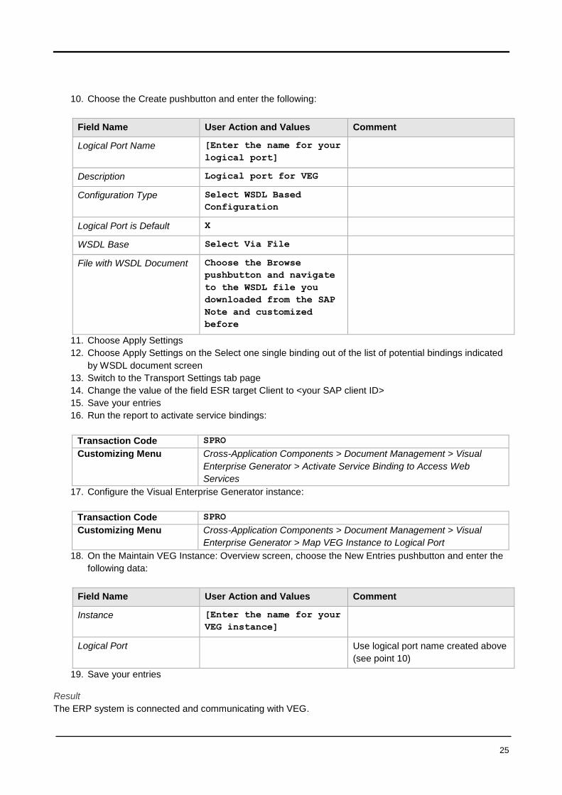
10. Choose the Create pushbutton and enter the following:
Field Name User Action and Values Comment
Logical Port Name [Enter the name for your
logical port]
Description Logical port for VEG
Configuration Type Select WSDL Based
Configuration
Logical Port is Default X
WSDL Base Select Via File
File with WSDL Document Choose the Browse
pushbutton and navigate
to the WSDL file you
downloaded from the SAP
Note and customized
before
11. Choose Apply Settings
12. Choose Apply Settings on the Select one single binding out of the list of potential bindings indicated
by WSDL document screen
13. Switch to the Transport Settings tab page
14. Change the value of the field ESR target Client to <your SAP client ID>
15. Save your entries
16. Run the report to activate service bindings:
Transaction Code SPRO
Customizing Menu Cross-Application Components > Document Management > Visual
Enterprise Generator > Activate Service Binding to Access Web
Services
17. Configure the Visual Enterprise Generator instance:
Transaction Code SPRO
Customizing Menu Cross-Application Components > Document Management > Visual
Enterprise Generator > Map VEG Instance to Logical Port
18. On the Maintain VEG Instance: Overview screen, choose the New Entries pushbutton and enter the
following data:
Field Name User Action and Values Comment
Instance [Enter the name for your
VEG instance]
Logical Port Use logical port name created above
(see point 10)
19. Save your entries
Result
The ERP system is connected and communicating with VEG.
26
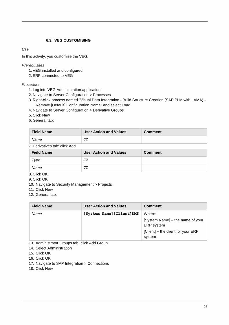
6.3. VEG CUSTOMISING
Use
In this activity, you customize the VEG.
Prerequisites
1. VEG installed and configured
2. ERP connected to VEG
Procedure
1. Log into VEG Administration application
2. Navigate to Server Configuration > Processes
3. Right-click process named "Visual Data Integration - Build Structure Creation (SAP PLM with LAMA) -
Remove [Default] Configuration Name" and select Load
4. Navigate to Server Configuration > Derivative Groups
5. Click New
6. General tab:
Field Name User Action and Values Comment
Name JT
7. Derivatives tab: click Add
Field Name User Action and Values Comment
Type JT
Name JT
8. Click OK
9. Click OK
10. Navigate to Security Management > Projects
11. Click New
12. General tab:
Field Name User Action and Values Comment
Name [System Name][Client]DMS Where:
[System Name] – the name of your
ERP system
[Client] – the client for your ERP
system
13. Administrator Groups tab: click Add Group
14. Select Administration
15. Click OK
16. Click OK
17. Navigate to SAP Integration > Connections
18. Click New

27
Field Name User Action and Values Comment
Type SAP RFC
SAP System [SAP System] Where:
[System Name] – the name of your
ERP system
Display Name Prepopulated when SAP System is
selected
Client [Client] Where:
[Client] – the client for your ERP
system
19. Click OK
20. Navigate to Server Configuration > Workflows
21. Right-click workflow named Visual Data Integration (SAP PLM Solidworks Integration) and select
Duplicate
22. Double-click the newly created workflow
23. General tab:
Field Name User Action and Values Comment
Name [Enter the name for your
workflow]
Choose something that is easily
identifiable; e.g. ERP Integration
[System Name] where [System
Name] is the name of your ERP
system
Description [Enter the description
for your workflow]
24. Processes tab:
Field Name User Action and Values Comment
SAP ERP structure creation Visual Data Integration
- Build Structure
Creation (SAP PLM with
LAMA) - Remove [Default]
Configuration Name
25. Settings tab:

28
Field Name User Action and Values Comment
Default Derivative Group JT
Manual SAP ERP Lock
Release Process
Visual Data Integration
– ERP Unlock For Job
Derivative build failure as
warning
True
DMS file path prefix C:\working\
Extract all configurations if
none specified
True
Maximum files per KPRO
task
50
Maximum KPRO store
attempts
5
PDM external system name [System
Name]/[Client]/SW
Where:
[System Name] – the name of your
ERP system
[Client] – the client for your ERP
system
SAP external system name [System
Name]/[Client]/VED
Where:
[System Name] – the name of your
ERP system
[Client] – the client for your ERP
system
SAP system connection Use connection created above (see
points 17-19)
Storage category Use one defined on KPRO
Instance ID Use one defined in your ERP
system that describes this VEG
installation
Project name Use VEG project name created
above (see points 10-16)
26. Click OK
Result
The VEG is customized.
6.4. ERP CUSTOMISING, VEG CONVERSION TRIGGER
In this Customizing activity, you maintain the document status at which the conversion or registration is triggered automatically or manually for a particular document type. Activities
1. Specify the Document Type for conversion.

29
2. Specify the Sequence number that uniquely identifies the Customizing entries when document type and application type are same. 3. Specify the Previous Document Status of a document for registering the document for conversion. 4. Specify the Document Status. This will either trigger conversion or registration for matching document statuses. 5. Select Auto Start if you want the registration of the documents belonging to a particular document type to be done automatically. 6. Specify one of the following Conversion Mode to be triggered:
Single File for a part file.
Actual for an assembly conversion.
Latest Released for an assembly conversion. Conversion is triggered for the document structure that is attached to the input document. All the child documents will be replaced by their latest released version correspondingly.
Single File Template if you want to tag business data to the converted file. Selecting this option allows you to convert an rh file into a pdf format that contains the relevant business data.
File with Dependency if you want to convert CAD files having dependent files that are required for conversion.
Latest in Structure for an assembly conversion. Conversion is triggered for the document structure that is attached to the input document. If there is a document that is repeated across several sub-assemblies in the document structure, then all the instances of such a document will be replaced by the highest version in document structure of this document.
Latest Version for an assembly conversion. Conversion is triggered for the document structure that is attached to the input document. All the child documents will be replaced by their latest version in the system correspondingly.
User Defined for controlling the behavior of explosion of Bill of Documents by implementing
BADI CDESK_SRV_DIR_STR of Enhancement Spot PLM_CDESK_SRV.
7. The Instance you specify determines the SAP 3D Visual Enterprise Generator's server logical port where conversion occurs. Note that VEG instance should be same as VEG server instance. You can see the settings in Customizing for Map VEG Instance to Logical Port under Cross-Application Components -> Document Management -> Visual Enterprise Generator. 8. Specify the Configuration ID based on the mode of conversion. This determines the format of the output file.
In this activity, you customize the ERP.
Prerequisites
1. VEG installed and configured
2. ERP connected to VEG
3. VEG customized
Procedure
1. Configure the conversion trigger:
Transaction Code SPRO
Customizing Menu Cross-Application Components > Document Management > Visual
Enterprise Generator > Maintain Conversion Trigger
2. On the DMS VEG Conversion Specifications: Overview screen, choose the New Entries pushbutton
and enter the following data:
Doc
Type Sequence
Application
Type
Document
Status
Auto
Start Conversion Instance Config ID
SWP 1 SWP AE X Actual <VEG_Instance>
defined
<VEG
workflow

30
If there is a document structure containing documents D1(SWP, SWP, AE), D2(SWP, SWP, AE),
D3(SWA, SWA, AE) such that D3 is top level document and D1 & D2 are child of D3 document, and
document D3 needs to be converted then below is the customizing for it
Doc
Type Sequence
Applicatio
n Type
Document
Status
Auto
Start
Conversio
n Instance Config ID
SWA 1 SWA AE X Actual <VEG_Instance>
defined
<VEG
workflow
name>
defined
SWP 1 SWP AE X Actual <VEG_Instance>
defined
<VEG
workflow
name>
defined
Result
The ERP is customized.
name>
defined

31
7. PRUDUCT STRUCTURE MANAGEMENT
In this Chapter is described how you can set up customer specific Objects in Product Structure Management
named PSM in all chapters. As PSM Customizing is based on Integrated Product and Process Engineering
Customizing, named iPPE, this will be described too. In the first Chapter the Standard Customizing is
described, if no specific objects where used.
7.1. PSM STANDARD CUSTOMIZING
These settings are used when no customer specific objects like Nodes, Variants or Relations needs to be set
up. If a customer uses individual objects go to the next Chapter.
7.1.1. PREFERENCE DOCUMENT ASSIGNMENT - STANDARD CUSTOMIZING-
Customizing Menu Customizing → Logistics - General → Product Lifecycle
Management (PLM) → PLM Web User Interface → Objects
in PLM Web UI → Product Structure and Assembly
Management I→ Define Settings for Product Structure
Transaction Code SPRO
Defines the priority rule for selecting document links for Digital Mockup (DMU) in Product Structure
Management (PSM).
M - Documents at the Material Preferred
First the material of the Product Item Variant is checked for linked documents with viewable files, if no
viewables are found the documents linked to the Product Item Variant are checked.
V - Documents at the Variant Preferred
First the Product Item Variant is checked for linked documents with viewable files, if no viewables are found
the documents linked to the material of the Product Item Variant are checked.
X - Documents at the Material Only
Only the material of the Product Item Variant is checked for linked documents with viewable files.
[No Value] - Documents at the Variant Only (default setting)
Only the Product Item Variant is checked for linked documents with viewable files.
Dependencies
The definition of the document types and viewable file extension which are relevant for DMU are done via
customizing 'Logistics - General', 'Product Lifecycle Management (PLM)', 'Visual Enterprise Generator',
7.1.2. PSM MAINTENANCE OF RELEVANT NODE TYPES (/PLMI/PPE_VIP_ND)
This customizing table specifies the allowed node types for which the VIP can be launched.
Customizing Menu Customizing → Logistics - General → Product Lifecycle
Management (PLM) → PLM Web User Interface → Objects
in PLM Web UI → Product Structure and Assembly
Management I→ Define Relevant Node Types of Geometric
Instances
Transaction Code SPRO

32
In this Customizing activity, you can define relevant node types for launching Visual Instance Planner (VIP).
VIP can only be launched for the node types defined here.
Requirements Elementary node types exist
Standard Settings In the standard system, the following node types are defined:
- S_HD Access Node
- S_ST Structure Node
- S_VW View Node
Example
Assume that you have to launch Visual Instance Planner/VIP from Product Structure Web UI or CAD
Desktop. You do the following:
1. Define node type of the node you want to launch VIP with in the customizing activity
2. Launch VIP from UI
7.1.3. PRODUCT VIEW -USER SETTINGS DEFINE PRIORITY FOR PSM STRUCTURE
Define the priority of the expanded structure for the Product Structure Management in the Product View
When Product View is selected, the Product Structure Management's structure expands and displays
information according to a priority, which is defined in the customizing table.
If "Only assembly" is defined in the customizing table, only the assembly is displayed
If "Only Material BOM" is defined in the customizing table, only the Material BOM is displayed
If "Assembly before Material BOM" is defined in the customizing table, only the assembly is displayed, but if
there is no assembly in the structure, the Material BOM is displayed
If "Material BOM before Assembly" is defined in the customizing table, only the Material BOM is displayed,
but if there is no Material BOM, the Assembly is displayed
Set Default user Settings for Product Structure Management
-