Embed Size (px)
Citation preview
Concrete structure management:Guide to ownership and good practiceContents
1 Keywords
2 Vision behind preparation of document
3 Introduction and scope of issues
4 The owners’ requirements and obligations
5 Implications of deterioration of concrete structures
6 Case histories – dealing with deterioration and extension of asset life
7 Engineering aspects of structure management
8 Process management
9 Application examples – works for the extension of asset life
10 Standards for the protection and repair of concrete structures
11 Some frequently asked questions (FAQ)
12 Future look and developments
13 References, websites and further reading
Appendix A: List of keywords
Appendix B: Examples of deterioration and repairs
Appendix C: EN 1504 series for repair and protection of concrete
Appendix D: Standards for protection and repair of concrete
Appendix E: Risk assessment and management
Appendix F: Benefits of pre-construction planning
Appendix G: Project specifications – an owner’s tool
fédération internationale du bétonInternational Federation for Structural Concrete www.fib-international.org
Concrete structure management:Guide to ownershipand good practice
gu
ide
to
go
od
pra
cti
ce
bulle
tin 4
4ISSN 1562-3610ISBN 978-2-88394-084-0
Co
nc
rete
str
uc
ture
ma
na
ge
me
nt:
Gu
ide
to
ow
ne
rsh
ip a
nd
go
od
pra
cti
ce
44
08-03-05-U44-wz.qxd 05.03.2008 9:41 Uhr Seite 1
Concrete structure management:
Guide to ownership and good practice
Guide to good practice prepared by Task Group 5.3
February 2008
Subject to priorities defined by the Technical Council and the Presidium, the results of fib’s work in Commissions and Task Groups are published in a continuously numbered series of technical publications called 'Bulletins'. The following categories are used:
category minimum approval procedure required prior to publication Technical Report approved by a Task Group and the Chairpersons of the Commission State-of-Art Report approved by a Commission Manual, Guide (to good practice) or Recommendation
approved by the Technical Council of fib
Model Code approved by the General Assembly of fib
Any publication not having met the above requirements will be clearly identified as preliminary draft. This Bulletin N° 44 was approved as an fib Guide to good practice by the Technical Council in May 2007.
Major contributors involved in the compilation of this guide were the following members of Task Group 5.3, Assessment, maintenance and rehabilitation, of Commission 5, Structural service life aspects:
Stuart Matthews (Convener, Building Research Establishment Ltd, United Kingdom)
Lojze Bevc (ZAG, Slovenia), Stuart Curtis (RTR Bridge Construction Services, Australia), Ainars Paeglitis (Riga Technical University, Latvia)
Written contributions were also provided by further members of the Task Group:
Julio Appleton (Instituto Superior Técnico Lisboa, Portugal), John Cairns (Heriot-Watt University, Edinburgh), David Cleland (Queens University Belfast, Northern Ireland), Josse Jacobs (CSTC-WTCB-BBRI, Belgium), Péter Lenkei (Pecs University, Hungary), Gábor A. Madaras (EMI-TÜV Bayern Ltd, Hungary), Toyoaki Miyagawa (Kyoto University, Japan), Brett Pielstick (Eisman & Russo Consulting, USA), Steen Rostam (Cowi A/S, Denmark), Irina Stipanovic (Zagreb University, Croatia), Harshavardhan Subba Rao (Construma Consultancy Pvt. Ltd., India), Øystein Vennesland (Norwegian University of Science and Technology, Norway), Tomás and Václav Vimmr (STú-K plc, Czech Republic) Full address details of Task Group members may be found in the fib Directory or through the online services on fib's website, www.fib-international.org. Cover photo: Example of bridge after intervention works (see Figure 32). © fédération internationale du béton (fib), 2008 Although the International Federation for Structural Concrete fib - féderation internationale du béton - does its best to ensure that any information given is accurate, no liability or responsibility of any kind (including liability for negligence) is accepted in this respect by the organisation, its members, servants or agents. All rights reserved. No part of this publication may be reproduced, modified, translated, stored in a retrieval system, or transmitted in any form or by any means, electronic, mechanical, photocopying, recording, or otherwise, without prior written permission. First published in 2008 by the International Federation for Structural Concrete (fib) Postal address: Case Postale 88, CH-1015 Lausanne, Switzerland Street address: Federal Institute of Technology Lausanne - EPFL, Section Génie Civil Tel +41 21 693 2747 • Fax +41 21 693 6245 [email protected] • www.fib-international.org ISSN 1562-3610 ISBN 978-2-88394-084-0 Printed by Sprint-Digital-Druck, Stuttgart
fib Bulletin 44: Concrete structure management: Guide to ownership and good practice iii
Preface The objective of this Guide is to provide owners with an understanding of: • Why they should be concerned about the management of their concrete structures
(buildings and infrastructure) as an aspect of meeting their business goals or the service objectives of their organisation and the contribution such assets make to these.
• What constitutes best practice in the management of concrete structures. • What their broad responsibilities are in relation to these activities, noting examples of
statutory and related duties. • How these activities relate to the wider context and issues of service life design to meet
the functional and related through-life issues associated with sustainable assets. • How they can engage with their supporting professional team of architects, engineers,
specifiers, contractors and others to enable them to achieve functional, durable buildings and infrastructure assets providing value for money in relation to the goals of the business or organisation concerned, whilst meeting their wider obligations and responsibilities.
• What information and direction is needed by the supporting professional team. The document also provides some background information upon matters such as deterioration processes and technical procedures used for the management of concrete structures, including reference to the evolving European standards (e.g. the series EN 206 Concrete, EN 13670 Execution of concrete structures, and EN 1504 Products and systems for the protection and repair of concrete structures – Definitions, requirements, quality control, evaluation of conformity) for the protection and repair of concrete structures. These activities are illustrated by some application examples / case histories and by a section addressing frequently asked questions. A brief review is made of some potential future developments. It is the intention of Commission 5 to complement this Guide by a: • Technical Report on Assessment and Remediation of Concrete Structures, and a • Model Technical Specification for The Remediation of Concrete Structures. Acknowledgements In addition to the authors listed on page ii, further significant contributions were received by the following members of Commission 5, Structural service life aspects: Vute Sirivivatnanon (CSIRO, Australia), Tamon Ueda (Hokkaido Univ., Japan), Aad Van der Horst (Delta Marine Consultants bv, The Netherlands) The valuable work of the previous fib Task Group 5.3.1, which provided a platform for aspects of this Guide to Good Practice, is acknowledged Also gratefully acknowledged are the contributions received from: Julie Bregulla (Building Research Establishment Ltd, United Kingdom), Jan Lindgård (Sintef, Noway), Hans-Ulrich Litzner (Deutscher Beton- und Bautechnik-Verein, Germany), Gro Markeset (Norwegian Building Research Institute, Norway), Eva Rodum (Norwegian Public Roads Administration, Norway), George Somerville (CARES, United Kingdom).
Dr. Stuart Matthews Convener, fib Task Group 5.3 Chair, fib Commission 5
Copyright fib, all rights reserved. This PDF copy of fib Bulletin 44 is intended for use and/or distribution only within National Member Groups of fib.
iv fib Bulletin 44: Concrete structure management: Guide to ownership and good practice
Contents
1 Keywords 1
2 Vision behind preparation of this guide 1
3 Introduction and scope of issues 3 3.1 Meeting owner’s business or service objectives 3 3.2 Phases in the life of an asset and their relative cost 3 3.3 Wider societal considerations and requirements 11
4 The owners’ requirements and obligations 21 4.1 Performance requirements 21
(4.1.1 Reliability and functionality)
4.2 Responsibilities and liabilities 23 (4.2.1 Economic and financial — 4.2.2 Societal and cultural aspects — 4.2.3 Environmental — 4.2.4 Risk management)
4.3 Value judgements, decision criteria and probabilistic concepts 35 4.4 Meeting the owner’s requirements 37
5 Implications of deterioration of concrete structures 39 5.1 General 39 5.2 Mechanisms of deterioration 42 5.3 Implications of deterioration 44
6 Case histories – dealing with deterioration and extension of asset life 47 6.1 Introduction 47 6.2 Ashby Building, Belfast 47 6.3 Krk Bridge, Croatia 50
(6.3.1 Krk Bridge - Cost analysis for the selective use of stainless steel)
7 Engineering aspects of structure management 55 7.1 Philosophy for structure management 55 7.2 Management systems for populations of structures 58 7.3 Planning and implementing through-life care of a structure 59
(7.3.1 Introduction — 7.3.2 Design and assessment considerations — 7.3.3 Maintenance class — 7.3.4 Types of through-life inspection and investigations)
7.4 Assessment of existing structures 66 7.5 Overview of repair and remediation methods 70 7.6 Selection of protection and repair options 72 7.7 Performance indicators 74
8 Process management 77 8.1 Establishing the professional team 77 8.2 Scenario selection 77 8.3 Scenario implementation / execution of works 79
Copyright fib, all rights reserved. This PDF copy of fib Bulletin 44 is intended for use and/or distribution only within National Member Groups of fib.
fib Bulletin 44: Concrete structure management: Guide to ownership and good practice v
8.4 Quality planning and verification during execution of works 80 (8.4.1 The role of the project specification — 8.4.2 The need for revised quality management concepts — 8.4.3 Prevention requires understanding of the execution processes — 8.4.4 Project quality management plan - illustration of contents)
8.5 Check list for owners 87
9 Application examples – works for the extension of asset life 89 9.1 Introduction 89 9.2 Steps for managing and making an intervention on a structure 90 9.3 Illustration of process - intervention works upon a bridge 93
10 Standards for the protection and repair of concrete structures 97
11 Some frequently asked questions (FAQ) 99
12 Future look and developments 107 12.1 Overview 107 12.2 Potential implications of climate change 109
13 References, websites and further reading 111
Appendix A: List of keywords 119
Appendix B: Examples of deterioration and repairs 129 B.1 Introduction 129 B.2 Commercial buildings 129 B.3 Hotel buildings 130 B.4 Tunnels 132 B.5 Concrete chimneys 133 B.6 Sewage treatment plants 134 B.7 Bridges 136 B.8 Car parks 138 B.9 Swimming pools 140 B.10 Wharves and coastal marine structures 141 B.11 Dams 143
Appendix C: EN 1504 series for repair and protection of concrete 147
Appendix D: Standards for protection and repair of concrete 151 D.1 Introduction 151 D.2 European standards 151 D.3 Japanese standards 153 D.4 Australian standards 155 D.5 US standards 157
Appendix E: Risk assessment and management 159 E.1 Introduction 159 E.2 Qualitative risk assessment 159 E.3 Quantitative risk assessment 164
Copyright fib, all rights reserved. This PDF copy of fib Bulletin 44 is intended for use and/or distribution only within National Member Groups of fib.
vi fib Bulletin 44: Concrete structure management: Guide to ownership and good practice
Appendix F: Benefits of pre-construction planning 169 F.1 Introduction 169 F.2 Some potential problems in producing durable concrete structures 171 F.3 Segment 1: Investigation of potential concrete supply problems 174 F.4 Segment 2: Research into verification of durability 174 F.5 Segment 3: Trial concrete mixes 175 F.6 Segment 4: Investigation of potential placement problems 176 F.7 Segment 5: Finalise construction requirements in project specification 177 F.8 Segment 6: Provision of adequate resources for quality management 177
Appendix G: Project specifications — An owner’s tool 179 G.1 General 179 G.2 The benefits of “thinking construction” 180 G.3 Standards for concrete structures and quality management 181
(G.3.1 Introduction — G.3.2 Hierarchy of European standards and the Execution Standard — G.3.3 Quality management in the Execution Standard — G.3.4 Quality management standards – ISO 9000 series of standards)
G.4 Improving the certainty of achieving durable concrete structures 185 G.5 Execution management and the requirement for supporting plans 187 G.6 The Execution Standard and the Inspection Plan 187 G.7 The Execution Standard and the Concreting Plan 188
(G.7.1 Introduction — G.7.2 Developing a specification clause for the execution specification — G.7.3 Linkage between the Concreting Plan and the Inspection Plan — G.7.4 The Inspection Plan — G.7.5 Procurement, production and delivery of concrete — G.7.6 The Reinforcement Plan — G.7.7 The Falsework Plan — G.7.8 The Post-tensioning Plan)
G.8 Products and systems used for repair of concrete structures 195 (G.8.1 Introduction — G.8.2 QC but no QA in EN 1504: Part 10 — G.8.3 Example of method 3.2 (recasting in concrete) in EN 1504: Part 10)
G.9 Supplementary documents to support the project execution specification 197 G.10 Summary 199 G.11 Concluding remarks 200
Copyright fib, all rights reserved. This PDF copy of fib Bulletin 44 is intended for use and/or distribution only within National Member Groups of fib.
fib Bulletin 44: Concrete structure management: Guide to ownership and good practice 1
1 Keywords Concrete structures, maintenance, repair, remediation, owner briefing, remaining life cost NB. Also refer to fib Bulletin 17, Management, maintenance and strengthening of concrete structures, Keyword definitions (Appendix 1). These have been updated and extended and the revised listing is reproduced in Appendix A.
2 Vision behind the preparation of this guide To help owners of concrete structures appreciate: (1) why they should be concerned about the management of these assets (2) the general nature of the responsibilities they have through ownership, and (3) the contribution that these assets can make to meeting the business goals or the service
objectives of their organisation. Furthermore it is hoped to make concerned parties, such as owners, aware of what constitutes best practice in the management of concrete structures. The document is divided into 13 main chapters and seven appendices, A - G, covering a range of topics concerned with the management of concrete structures, together with measures for their protection and repair. Chapter 3 provides an introduction and sets out the scope of issues involved in meeting the owner’s business or service objectives, setting down the phases in the life of an asset and their relative cost. It also draws attention to the wider societal considerations and requirements that are likely to have an influence upon the management of concrete structures. Chapter 4 sets down the owners’ obligations outlining considerations of the performance requirements which may need to be met and the roles of the various actors involved, considerations of reliability and functionality, as well as the associated responsibilities and associated liabilities under the headings of: • Economic and financial perspectives • Societal and cultural aspects • Environmental matters, and • Risk management issues. The chapter also discusses value judgements, decision criteria and the potential application of probabilistic concepts to address uncertainty and risks associated with decision making in these circumstances. The potential contribution that the Birth Certificate may make towards meeting the owner’s requirements is explored. Chapter 5 examines the implications of the deterioration of concrete structures, outlining some of the potential mechanisms of deterioration and the implications of such deterioration upon the service life of the structure. Chapter 6 presents two case histories which deal with some of the issues of deterioration and the means employed to extend the life of concrete structures and other assets. The examples presented are for the Ashby Building, Belfast and for the Krk Bridge, Croatia. The later includes a theoretical cost analysis for the selective use of stainless steel, showing how the adoption of the “design-out” approach when the structure was built would potentially have
Copyright fib, all rights reserved. This PDF copy of fib Bulletin 44 is intended for use and/or distribution only within National Member Groups of fib.

2 2 Vision behind the preparation of this guide
avoided the development of deterioration and would saved considerable through-life expense on concrete protection and repair works. Chapter 7 explores the engineering aspects of structure management, describing a philosophy for structure management, the implications for the management of populations of structures, and comments upon inspection, testing and assessment methodologies. An overview of repair and remediation methods is presented along with approaches to the selection of protection and repair options. Potential approaches to the use of performance indicators are discussed and a simplified methodology for the selection and monitoring of methods for the protection and repair of concrete structures is set down. Chapter 8 is concerned with the management of the overall inspection, assessment and intervention process. The steps discussed include establishing the professional team, selection of an appropriate scenario for managing the structure, how that scenario might be implemented, including the execution of works involved. Associated considerations include quality assurance (QA) and quality control (QC) of the execution of the works, the role of the project specification and ways of improving the application of QA and QC concepts. The report indicates that a thorough understanding of the proposed execution processes is required in order to ensure that effective preventive procedures are put into place to achieve the desired quality and reliability in the execution (construction) process. A check list is provided to guide owners and other concerned parties. Chapter 9 presents an application example of aspects of the works associated with the extension of asset life, dealing with the steps involved in managing and making an intervention on a structure. The overall process and application of the philosophy outlined in the report is illustrated by the example of intervention works undertaken upon a bridge. Chapter 10 discusses some of the standards and guidance available for the protection and repair of concrete structures, noting that further explanation and insight in these matters is given in Appendices C and D. Chapter 11 presents a number of frequently asked questions (FAQ) providing answers which detail points and matters that might be considered in the particular circumstances. A total of fourteen questions are treated. The responses are applicable to a wider range of circumstances. Chapter 12 provides some comment upon future developments, noting some of the potential implications of climate change upon the management of existing structures. Chapter 13 sets down references, websites and other sources of additional information and further reading. The seven appendices cover the following topics: • Appendix A: Keywords. • Appendix B: Examples of deterioration and repair works. • Appendix C: EN 1504 series for repair and protection of concrete. • Appendix D: Standards for protection and repair of concrete including an introduction to
relevant European standards, Japanese standards, Australian standards and US standards. • Appendix E: Risk assessment and management. • Appendix F: Benefits of pre-construction planning • Appendix G: Project specifications – An owner’s tool.
Copyright fib, all rights reserved. This PDF copy of fib Bulletin 44 is intended for use and/or distribution only within National Member Groups of fib.
fib Bulletin 44: Concrete structure management: Guide to ownership and good practice 3
3 Introduction and scope of issues 3.1 Meeting owner’s business or service objectives
Construction projects are undertaken to fulfil various business or service objectives, as well as aspirational needs. It is self-evident that the success of a building or an element of infrastructure (generally referred to as facilities or assets in this report) depends on how well it meets either the owner’s needs and interests or those of the users. Recent changes in owner attitudes to construction are reflected in an increasing interest in through-life costs, that is, not only the capital costs of construction but particularly in the operational costs associated with delivery of functional performance for a defined life span (Kernohan et al 1996, Royal Academy of Engineering 1998). In the past these costs have often been viewed in isolation as they have not been considered on a holistic basis, but have been allocated to different budgets (e.g. perhaps as a capital expenditure account and as a revenue account, each possibly controlled by different management teams). It is acknowledged that the owner can greatly improve the likelihood of achieving the value they seek from the facility by being intimately and effectively involved in the definition of performance requirements at the start of the construction procurement process. Clear vision and direction are important elements for success. In these evaluations recognition needs to be given to the business benefits that can be gained from improvements in functional effectiveness of facilities bearing in mind that the value of the function(s) performed will typically be some one to two orders of magnitude (i.e. 10 to 100 times) or more larger than the direct operational costs (energy, maintenance etc) [Refs: Royal Academy of Engineering 1998, Prior and Rizzi 2003].
3.2 Phases in the life of an asset and their relative cost
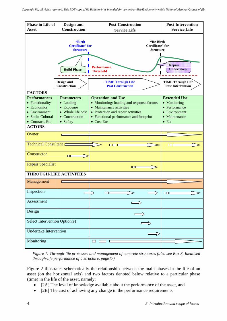
There are a number of phases in the development and use of an asset. Typically the sequence of events through the life of the asset progresses as follows: • Concept phase - where the owner’s basic requirements and needs are established. • Design - usually involving preliminary and detailed design phases. • Construction - the process whereby the asset is built. • Operation and use - through life performance and maintenance of its functionality. • Disposal - the process by which the asset is either sold, decommissioned or removed. Figure 1 depicts the hypothetical through-life performance of a structure. It shows the different phases in the service life of a concrete structure. It incorporates the periods of design and construction, post-construction service life, the remedial intervention process and also post- intervention performance. It shows the general steps and activities involved. The figure also identifies the various actors which might be involved in an intervention to extend the useful service life of the structure, giving a general indication of their possible participation, intervention activities and decision making, plus post-intervention performance monitoring. Some parameters and other aspects which influence the potential durability and service-life of the structure are listed. Such parameters might provide a basis for modelling the performance of the structure and for developing better acceptance and performance criteria which might be utilised by the owner for through-life management of the structure.
Copyright fib, all rights reserved. This PDF copy of fib Bulletin 44 is intended for use and/or distribution only within National Member Groups of fib.
4 3 Introduction and scope of issues
Phase in Life of Asset
Design and Construction
Post-Construction Service Life
Post-Intervention Service Life
FACTORS Performances • Functionality • Economics • Environment • Socio-Cultural • Contracts Etc
Parameters • Loading • Exposure • Whole life cost • Construction • Safety
Operation and Use • Monitoring: loading and response factors • Maintenance activities • Protection and repair activities • Functional performance and footprint • Cost Etc
Extended Use • Monitoring • Performance • Environment • Maintenance • Etc
ACTORS
Owner
Technical Consultant
Constructor
Repair Specialist
THROUGH-LIFE ACTIVITIES
Management
Inspection
Assessment
Design
Select Intervention Option(s)
Undertake Intervention
Monitoring
Figure 1: Through-life processes and management of concrete structures (also see Box 3, Idealised through-life performance of a structure, page17)
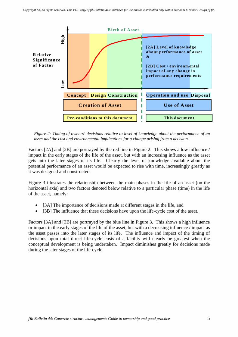
Figure 2 illustrates schematically the relationship between the main phases in the life of an asset (on the horizontal axis) and two factors denoted below relative to a particular phase (time) in the life of the asset, namely:
• [2A] The level of knowledge available about the performance of the asset, and • [2B] The cost of achieving any change in the performance requirements
“Birth Certificate” for
Structure
“Re-Birth Certificate” for
Structure
Performance Threshold
Repair Undertaken
Design and Construction
TIME Through Life Post Construction
TIME Through LifePost Intervention
Build Phase
Copyright fib, all rights reserved. This PDF copy of fib Bulletin 44 is intended for use and/or distribution only within National Member Groups of fib.
fib Bulletin 44: Concrete structure management: Guide to ownership and good practice 5
[2A ] Level of know ledge about performance of asset & [2B ] C ost / environmental impact of any change in performance requirements
R elative Significance of F actor
Low
H
igh
C reation of A sset U se of A sset
Pre-conditions to this document This docum ent
D isposalO peration and use C onstructionD esignC oncept
B irth of A sset
Figure 2: Timing of owners’ decisions relative to level of knowledge about the performance of an asset and the cost and environmental implications for a change arising from a decision.
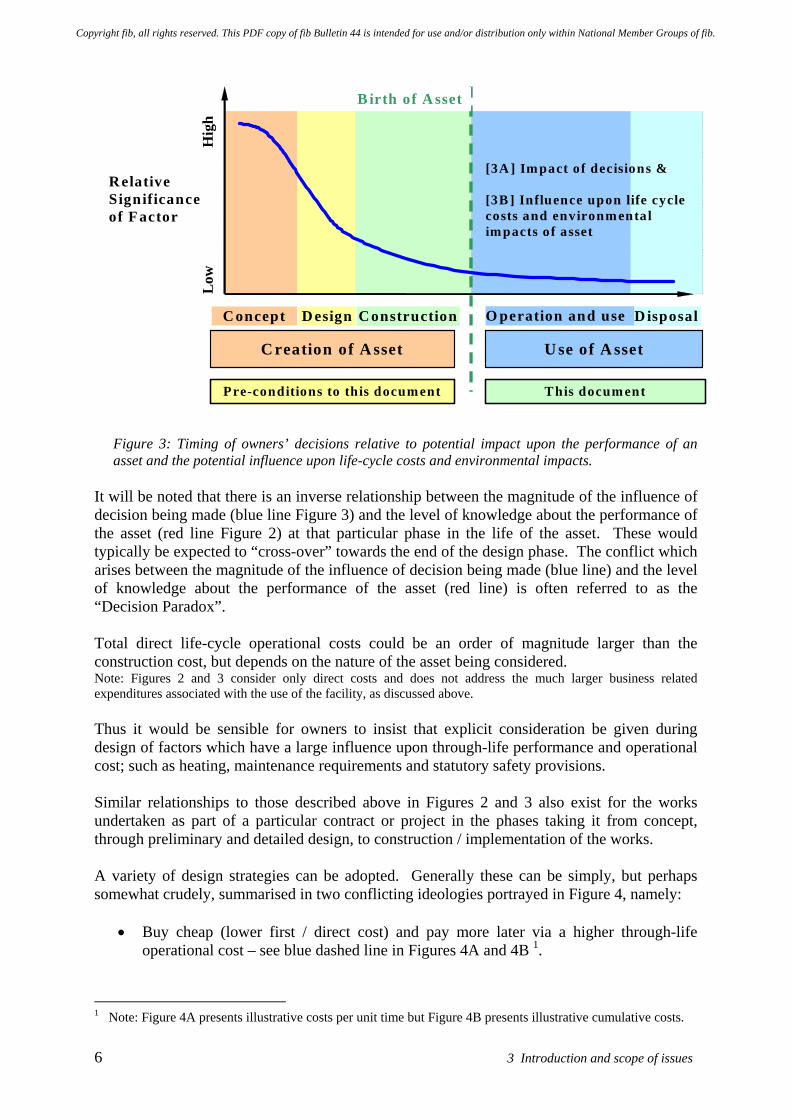
Factors [2A] and [2B] are portrayed by the red line in Figure 2. This shows a low influence / impact in the early stages of the life of the asset, but with an increasing influence as the asset gets into the later stages of its life. Clearly the level of knowledge available about the potential performance of an asset would be expected to rise with time, increasingly greatly as it was designed and constructed. Figure 3 illustrates the relationship between the main phases in the life of an asset (on the horizontal axis) and two factors denoted below relative to a particular phase (time) in the life of the asset, namely:
• [3A] The importance of decisions made at different stages in the life, and • [3B] The influence that these decisions have upon the life-cycle cost of the asset.
Factors [3A] and [3B] are portrayed by the blue line in Figure 3. This shows a high influence or impact in the early stages of the life of the asset, but with a decreasing influence / impact as the asset passes into the later stages of its life. The influence and impact of the timing of decisions upon total direct life-cycle costs of a facility will clearly be greatest when the conceptual development is being undertaken. Impact diminishes greatly for decisions made during the later stages of the life-cycle.
Copyright fib, all rights reserved. This PDF copy of fib Bulletin 44 is intended for use and/or distribution only within National Member Groups of fib.
6 3 Introduction and scope of issues
[3A ] Im pact of decisions & [3B ] Influence upon life cycle costs and environmental impacts of asset
R elative Significance of F actor
Low
H
igh
C reation of A sset U se of A sset
Pre-conditions to this document This docum ent
D isposalO peration and use C onstructionD esignC oncept
B irth of A sset
Figure 3: Timing of owners’ decisions relative to potential impact upon the performance of an asset and the potential influence upon life-cycle costs and environmental impacts.
It will be noted that there is an inverse relationship between the magnitude of the influence of decision being made (blue line Figure 3) and the level of knowledge about the performance of the asset (red line Figure 2) at that particular phase in the life of the asset. These would typically be expected to “cross-over” towards the end of the design phase. The conflict which arises between the magnitude of the influence of decision being made (blue line) and the level of knowledge about the performance of the asset (red line) is often referred to as the “Decision Paradox”. Total direct life-cycle operational costs could be an order of magnitude larger than the construction cost, but depends on the nature of the asset being considered. Note: Figures 2 and 3 consider only direct costs and does not address the much larger business related expenditures associated with the use of the facility, as discussed above. Thus it would be sensible for owners to insist that explicit consideration be given during design of factors which have a large influence upon through-life performance and operational cost; such as heating, maintenance requirements and statutory safety provisions. Similar relationships to those described above in Figures 2 and 3 also exist for the works undertaken as part of a particular contract or project in the phases taking it from concept, through preliminary and detailed design, to construction / implementation of the works. A variety of design strategies can be adopted. Generally these can be simply, but perhaps somewhat crudely, summarised in two conflicting ideologies portrayed in Figure 4, namely:
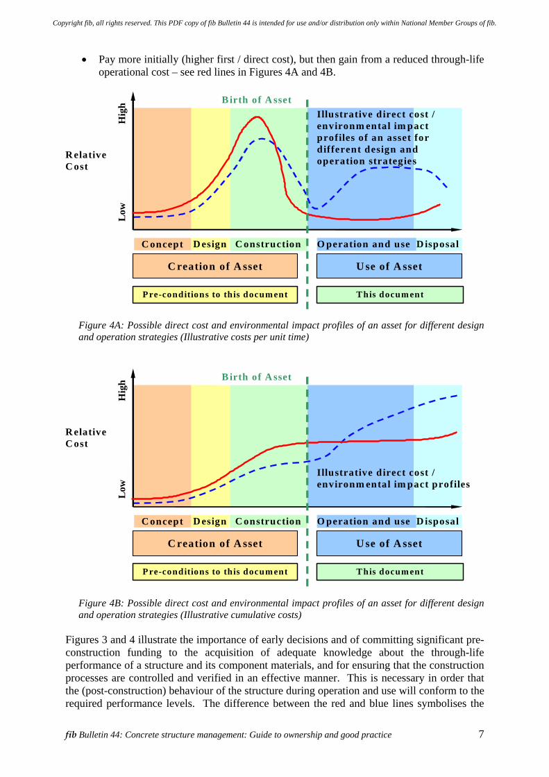
• Buy cheap (lower first / direct cost) and pay more later via a higher through-life operational cost – see blue dashed line in Figures 4A and 4B 1.
1 Note: Figure 4A presents illustrative costs per unit time but Figure 4B presents illustrative cumulative costs.
Copyright fib, all rights reserved. This PDF copy of fib Bulletin 44 is intended for use and/or distribution only within National Member Groups of fib.
fib Bulletin 44: Concrete structure management: Guide to ownership and good practice 7
• Pay more initially (higher first / direct cost), but then gain from a reduced through-life operational cost – see red lines in Figures 4A and 4B.
Illustrative direct cost / environm ental im pact profiles of an asset for different design and operation strategies R elative
C ost
Low
H
igh
C reation of A sset U se of A sset
Pre-conditions to this docum ent This docum ent
B irth of A sset
D esign D isposalO peration and use C onstructionC oncept
Figure 4A: Possible direct cost and environmental impact profiles of an asset for different design and operation strategies (Illustrative costs per unit time)
R elative C ost
Low
H
igh
C reation of A sset U se of A sset
Pre-conditions to this docum ent This docum ent
B irth of A sset
D esign D isposalO peration and use C onstructionC oncept
Illustrative direct cost / environm ental im pact profiles
Figure 4B: Possible direct cost and environmental impact profiles of an asset for different design and operation strategies (Illustrative cumulative costs)
Figures 3 and 4 illustrate the importance of early decisions and of committing significant pre-construction funding to the acquisition of adequate knowledge about the through-life performance of a structure and its component materials, and for ensuring that the construction processes are controlled and verified in an effective manner. This is necessary in order that the (post-construction) behaviour of the structure during operation and use will conform to the required performance levels. The difference between the red and blue lines symbolises the
Copyright fib, all rights reserved. This PDF copy of fib Bulletin 44 is intended for use and/or distribution only within National Member Groups of fib.
8 3 Introduction and scope of issues
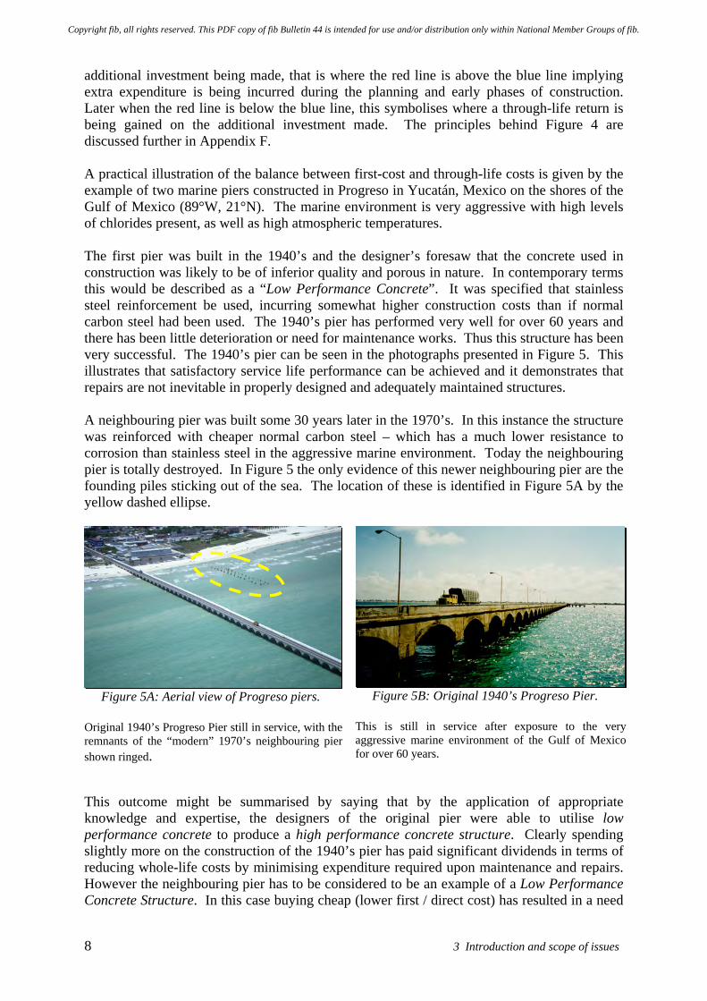
additional investment being made, that is where the red line is above the blue line implying extra expenditure is being incurred during the planning and early phases of construction. Later when the red line is below the blue line, this symbolises where a through-life return is being gained on the additional investment made. The principles behind Figure 4 are discussed further in Appendix F. A practical illustration of the balance between first-cost and through-life costs is given by the example of two marine piers constructed in Progreso in Yucatán, Mexico on the shores of the Gulf of Mexico (89°W, 21°N). The marine environment is very aggressive with high levels of chlorides present, as well as high atmospheric temperatures. The first pier was built in the 1940’s and the designer’s foresaw that the concrete used in construction was likely to be of inferior quality and porous in nature. In contemporary terms this would be described as a “Low Performance Concrete”. It was specified that stainless steel reinforcement be used, incurring somewhat higher construction costs than if normal carbon steel had been used. The 1940’s pier has performed very well for over 60 years and there has been little deterioration or need for maintenance works. Thus this structure has been very successful. The 1940’s pier can be seen in the photographs presented in Figure 5. This illustrates that satisfactory service life performance can be achieved and it demonstrates that repairs are not inevitable in properly designed and adequately maintained structures. A neighbouring pier was built some 30 years later in the 1970’s. In this instance the structure was reinforced with cheaper normal carbon steel – which has a much lower resistance to corrosion than stainless steel in the aggressive marine environment. Today the neighbouring pier is totally destroyed. In Figure 5 the only evidence of this newer neighbouring pier are the founding piles sticking out of the sea. The location of these is identified in Figure 5A by the yellow dashed ellipse.
Figure 5A: Aerial view of Progreso piers. Original 1940’s Progreso Pier still in service, with the remnants of the “modern” 1970’s neighbouring pier shown ringed.
Figure 5B: Original 1940’s Progreso Pier.
This is still in service after exposure to the very aggressive marine environment of the Gulf of Mexico for over 60 years.
This outcome might be summarised by saying that by the application of appropriate knowledge and expertise, the designers of the original pier were able to utilise low performance concrete to produce a high performance concrete structure. Clearly spending slightly more on the construction of the 1940’s pier has paid significant dividends in terms of reducing whole-life costs by minimising expenditure required upon maintenance and repairs. However the neighbouring pier has to be considered to be an example of a Low Performance Concrete Structure. In this case buying cheap (lower first / direct cost) has resulted in a need
Copyright fib, all rights reserved. This PDF copy of fib Bulletin 44 is intended for use and/or distribution only within National Member Groups of fib.
fib Bulletin 44: Concrete structure management: Guide to ownership and good practice 9
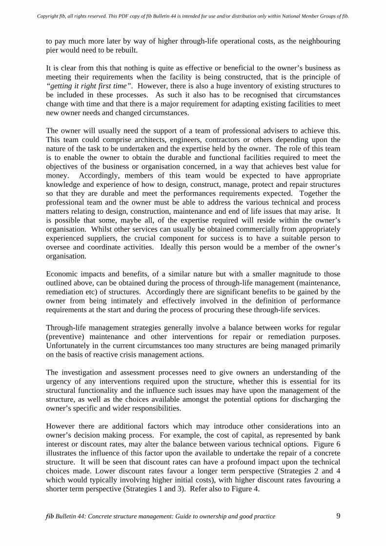
to pay much more later by way of higher through-life operational costs, as the neighbouring pier would need to be rebuilt. It is clear from this that nothing is quite as effective or beneficial to the owner’s business as meeting their requirements when the facility is being constructed, that is the principle of “getting it right first time”. However, there is also a huge inventory of existing structures to be included in these processes. As such it also has to be recognised that circumstances change with time and that there is a major requirement for adapting existing facilities to meet new owner needs and changed circumstances. The owner will usually need the support of a team of professional advisers to achieve this. This team could comprise architects, engineers, contractors or others depending upon the nature of the task to be undertaken and the expertise held by the owner. The role of this team is to enable the owner to obtain the durable and functional facilities required to meet the objectives of the business or organisation concerned, in a way that achieves best value for money. Accordingly, members of this team would be expected to have appropriate knowledge and experience of how to design, construct, manage, protect and repair structures so that they are durable and meet the performances requirements expected. Together the professional team and the owner must be able to address the various technical and process matters relating to design, construction, maintenance and end of life issues that may arise. It is possible that some, maybe all, of the expertise required will reside within the owner’s organisation. Whilst other services can usually be obtained commercially from appropriately experienced suppliers, the crucial component for success is to have a suitable person to oversee and coordinate activities. Ideally this person would be a member of the owner’s organisation. Economic impacts and benefits, of a similar nature but with a smaller magnitude to those outlined above, can be obtained during the process of through-life management (maintenance, remediation etc) of structures. Accordingly there are significant benefits to be gained by the owner from being intimately and effectively involved in the definition of performance requirements at the start and during the process of procuring these through-life services. Through-life management strategies generally involve a balance between works for regular (preventive) maintenance and other interventions for repair or remediation purposes. Unfortunately in the current circumstances too many structures are being managed primarily on the basis of reactive crisis management actions. The investigation and assessment processes need to give owners an understanding of the urgency of any interventions required upon the structure, whether this is essential for its structural functionality and the influence such issues may have upon the management of the structure, as well as the choices available amongst the potential options for discharging the owner’s specific and wider responsibilities. However there are additional factors which may introduce other considerations into an owner’s decision making process. For example, the cost of capital, as represented by bank interest or discount rates, may alter the balance between various technical options. Figure 6 illustrates the influence of this factor upon the available to undertake the repair of a concrete structure. It will be seen that discount rates can have a profound impact upon the technical choices made. Lower discount rates favour a longer term perspective (Strategies 2 and 4 which would typically involving higher initial costs), with higher discount rates favouring a shorter term perspective (Strategies 1 and 3). Refer also to Figure 4.
Copyright fib, all rights reserved. This PDF copy of fib Bulletin 44 is intended for use and/or distribution only within National Member Groups of fib.
10 3 Introduction and scope of issues
0
50
100
150
200
250
300
350
400
450
500
0 0.05 0.1 0.15 0.2 0.25 0.3 0.35Real rate of interest
Cos
t [U
S$/1
000]
Strategy 1Strategy 2Strategy 3Strategy 4
Figure 6: Influence of discount rates upon the choice of repair strategy for a concrete quay exposed to a marine environment
Parameters Associated with Figure 6 Example Required service life: 50 years Climates: 10 deg C and 30 deg C Design approach: Four alternative repair strategies - utilising probabilistic service life
performance analysis Strategy 1: Traditional concrete grade and carbon steel, allowing for one repair. Strategy 2: High Performance Concrete and large cover to carbon steel. Strategy 3: Traditional concrete grade and carbon steel, with the use of cathodic protection later. Strategy 4: Traditional concrete grade and carbon steel, selective use of stainless steel rebar.
It will be appreciated from the comments made above that decisions made and activities undertaken in the earlier phases in the life of an asset have a profound impact upon its subsequent through-life performance. This applies to both the Post-Construction and the Post-Intervention Service Life phases (refer Figure 1). An important influence upon through-life performance and associated whole-life cost of ownership is the durability of the structure. Durability, however this characteristic may be specified or evaluated, is generally a property of the cover concrete. Unfortunately this is the part of a reinforced concrete structure which is most vulnerable to poor workmanship. Not surprisingly the sensitivity to poor workmanship is greatest when the asset is situated within an aggressive environment. There is concern amongst some experienced engineers and construction personnel that quality management procedures employed during the design and construction of concrete structures do not always achieve satisfactory product quality and hence durability. An aspect of these concerns is that the overall standard of workmanship being achieved during the construction phase (referred to as the execution stage) is not always sufficiently high. However, these problems will often have their roots within earlier stages of the project; such as when the design, detailing or material specification tasks are carried out. Special efforts, primarily in
Copyright fib, all rights reserved. This PDF copy of fib Bulletin 44 is intended for use and/or distribution only within National Member Groups of fib.
fib Bulletin 44: Concrete structure management: Guide to ownership and good practice 11
the form of pre-planning construction activities and verification of the processes adopted during execution, can be required to overcome these potential difficulties. In addition there can be a marked difference between employing what in isolation might be taken to be high performance materials and actually achieving a high performance concrete structure which has adequate durability, as the example of the Progreso piers illustrates. These issues are discussed in more detail in later sections of this report.
3.3 Wider societal considerations and requirements
In addition it should be recognised that these economic considerations need to be set within the wider framework of sustainability related issues which society now expects the construction industry to address. Sustainability is not considered solely in environmental terms and there are a number of interacting and potentially conflicting issues and factors that need to be addressed and balanced. Figure 7 illustrates the primary headings under which matters relating to this topic are often broadly grouped. Again these relate to both the construction phase and the processes for through-life management. The Functional factors are often referred to as being technical requirements, whereas the other topics concerned with Economic, Socio-cultural and Environmental factors are sometimes referred to collectively as being non-technical requirements.
Client needsEnvironmental factors
Economic factors
Functional factors
Socio-culturalfactors
Figure 7: Components of sustainable construction [Quillin et al 2002]
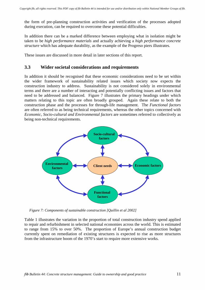
Table 1 illustrates the variation in the proportion of total construction industry spend applied to repair and refurbishment in selected national economies across the world. This is estimated to range from 15% to over 50%. The proportion of Europe’s annual construction budget currently spent on remediation of existing structures is expected to rise as more structures from the infrastructure boom of the 1970’s start to require more extensive works.
Copyright fib, all rights reserved. This PDF copy of fib Bulletin 44 is intended for use and/or distribution only within National Member Groups of fib.
12 3 Introduction and scope of issues
Table 1: Total construction industry spend (all materials) Country New Build
% Repair & Refurbishment
% Year
Japan 85 15 1995 USA 71 29 1993
France 70 30 1993 Germany 69 31 1995
50 50 1995 UK 47 53 2000
NB: After Tamon Ueda, fib Congress, Osaka, 2002
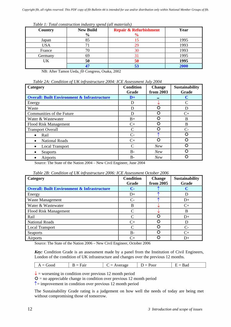
Table 2A: Condition of UK infrastructure 2004: ICE Assessment July 2004 Category
Condition Grade
Change from 2003
Sustainability Grade
Overall: Built Environment & Infrastructure D+ 0 C Energy D ↓ C Waste D D Communities of the Future D C+ Water & Wastewater B+ B Flood Risk Management C+ B Transport Overall C C-
• Rail C- ↑ • National Roads C+ • Local Transport C New • Seaports B- New • Airports B- New Source: The State of the Nation 2004 – New Civil Engineer, June 2004
Table 2B: Condition of UK infrastructure 2006: ICE Assessment October 2006
Category
Condition Grade
Change from 2005
Sustainability Grade
Overall: Built Environment & Infrastructure C- ↑ C Energy D+ ↑ D Waste Management C- ↑ D+ Water & Wastewater B ↓ C+ Flood Risk Management C ↓ B Rail C D+ National Roads C+ D Local Transport C C- Seaports B- C+ Airports C+ D+
Source: The State of the Nation 2006 – New Civil Engineer, October 2006 Key: Condition Grade is an assessment made by a panel from the Institution of Civil Engineers, London of the condition of UK infrastructure and changes over the previous 12 months.
A = Good B = Fair C = Average D = Poor E = Bad
↓ = worsening in condition over previous 12 month period = no appreciable change in condition over previous 12 month period
↑= improvement in condition over previous 12 month period
The Sustainability Grade rating is a judgement on how well the needs of today are being met without compromising those of tomorrow.
Copyright fib, all rights reserved. This PDF copy of fib Bulletin 44 is intended for use and/or distribution only within National Member Groups of fib.
fib Bulletin 44: Concrete structure management: Guide to ownership and good practice 13
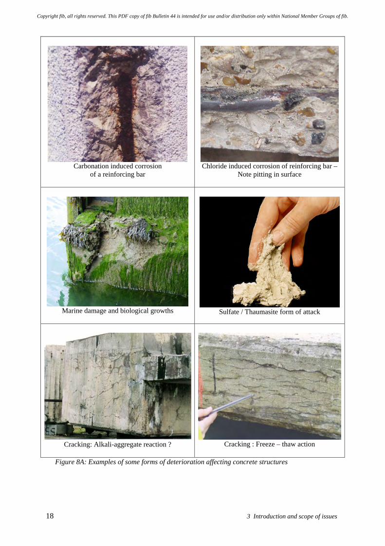
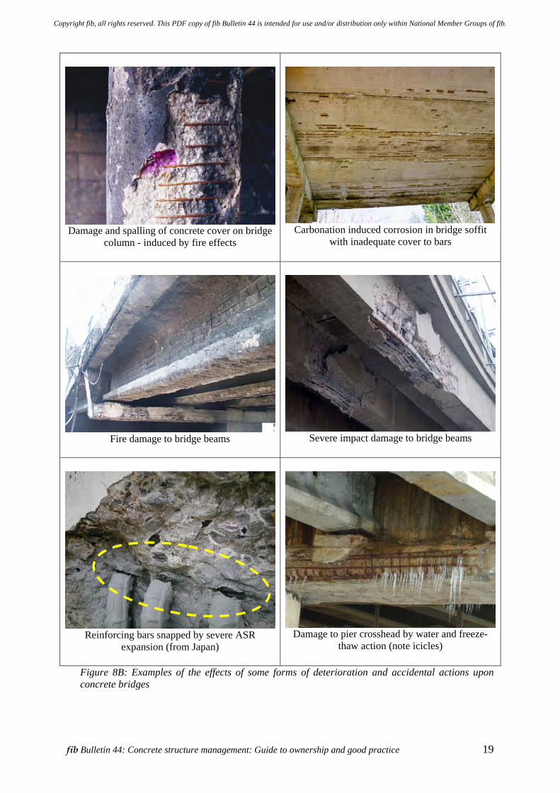
Historically in many parts of the world we have not been good at looking after the built assets upon which society depends. Some insight into these issues is given by Table 2 which reports two separate assessments made of the state of the UK’s infrastructure by the Institution of Civil Engineers, London for 2004 and 2006. The evaluations made are presented as Tables 2A and 2B. Their overall evaluation for 2004 was that the state was poor (D+) and showed no improvement from the previous year. Conversely in 2006 it was judged that some small improvement had occurred over the preceding year, with the overall evaluation being that the state was then fair (C-). Between 2004 and 2006 the changes occurring in the different sectors were mixed, with some showing improvement and others a small decline. Thus there is a backlog of work to be undertaken to improve the condition of these assets. The situation is believed to be broadly comparable in a number of countries, with similar surveys and assessments being undertaken by other engineering and professional bodies around the world. Accordingly maintenance and remediation works are expected to become an increasingly important economic activity in almost all developed countries. For example, the United State is facing a daunting number of aging structures that will require the development of new and better methods for the assessment and rehabilitation of each structure. With such a large developing need and the resource needed for the repair and rehabilitation, the United States continues to look for better and cheaper methods for the assessment and rehabilitation of its structures. The United States Federal Highway Association (FHWA) estimates the average annual investment to address all backlogged or accruing bridge deficiencies for years 1992-2001 as a massive US$8.2 billion. Through State agencies the FHWA has relied heavily on PONTIS, a network level management system which at this time does not address estimating repair or rebuild alternatives. Research and implementation of this program is focusing on forecast of maintenance costs and inventory conditions and providing priorities for rehabilitation and replacement. Social, economic and environmental benefits should follow from remedial works, by improving the reliability of civil infrastructure and improving remediation processes with improved quality in terms of cost efficiency and reduction in production time, maintenance costs, energy consumption, pollution (including noise), health risks and accidents. Turning our attention to concrete, globally it is the most widely used construction material in buildings and civil engineering structures. Concrete is a reliable and relatively cheap material that will remain important in the future. Over the years the type and quality of concrete materials and construction methods have varied considerably. As time has progressed there has been an increased understanding of the mechanisms underlying the behaviour of concrete and its performance in service. Figures 8A and 8B illustrate the nature of some of the forms of deterioration affecting concrete structures. It is an unfortunate, but inescapable, fact that all structures will deteriorate with time, though the rate at which they deteriorate varies considerably, as it is affected by many factors. Whilst most concrete structures will provide satisfactory performance over many decades, there are still a significant number of structures that experience varying degrees of premature deterioration and require repair. Deterioration will typically change the performance and the appearance of a structure, which may affect its functionality under normal working conditions. These difficulties are often compounded by a lack of appropriate maintenance.
Copyright fib, all rights reserved. This PDF copy of fib Bulletin 44 is intended for use and/or distribution only within National Member Groups of fib.
14 3 Introduction and scope of issues
Without timely intervention this could affect the safety of the structure, that of the general public or those using it. Owners increasingly want more certainty in the performance of new and remediated structures, together with improved financial control and cost certainty in order to integrate maintenance and remediation into their planning and resource allocation activities. Ideally owners would like the design service life to be guaranteed. They would also like the time and money involved in maintenance and remediation activities to be known in advance, along with the likely impact of these actions upon the owner’s business or service function. The current standards for design give indications of the notional design service life required and this is often taken to be 50 years – see Box 1. It should be appreciated that these values are not based upon a deterministic process, but are assumptions. They define broad expectations arrived at by drawing upon experience of the performance of existing structures and assets. Different types of structure may have a longer or shorter notional design service life. For example this could be relatively short for a temporary structure, e.g. perhaps some form of industrial building – see Box 1. In almost all countries the notional service life required for concrete structures, such as bridges and the like, forming part of a national infrastructure network is usually set at 100 years, or more. However the notional design service life has not always been achieved in severe or adverse environments. Many concrete structures are simply not yet old enough to be able to judge whether this will be so. The requirements set down in national or international design codes and standards are important because of their technical and legal implications for the structure(s) concerned. Concepts such as design service life requires careful definition so that all parties involved have a clear understanding of the objective and of the performance expectations so created for the particular structure. The owner needs to pay attention to this important issue as it is a fundamental requirement and expectation which must be effectively communicated to the professional team dealing with the particular structure. It is also important to recognise that design codes and standards are, by definition, consensus documents. They are developed and evolve over time on the basis of committee participation, typically involving a wide range of interested parties from throughout the supply chain. These processes potentially take a number of years to complete, especially for international documents. As a result codes and standards are unlikely to be able to reflect the latest thinking or state-of-the art industry practices. They have to establish common ground in order to achieve consensus and accordingly their content and approach may set a standard towards the lower end of any potential performance scale. As such their recommendations may not be adequate for particularly demanding situations. In a service life context this may mean that the general durability related provisions in design codes and standards may not be appropriate to meet an owner’s performance requirements, especially in severe exposure or long-life situations. Consideration of performance during the service life will also embrace the owner’s or operator’s responsibility for the level of routine maintenance to be provided throughout the service life. It is an unfortunate fact that the need for such activities is often either overlooked or is an early casualty of financial constraints. The designer of the concrete structure should be entitled to assume that the owner will ensure that basic husbandry of non-structural components / systems such as gutters and downpipes is carried out at appropriate intervals to avoid overflow and leakage so that the environmental conditions experienced by the structure are the same as those on which the design was based.
Copyright fib, all rights reserved. This PDF copy of fib Bulletin 44 is intended for use and/or distribution only within National Member Groups of fib.
fib Bulletin 44: Concrete structure management: Guide to ownership and good practice 15
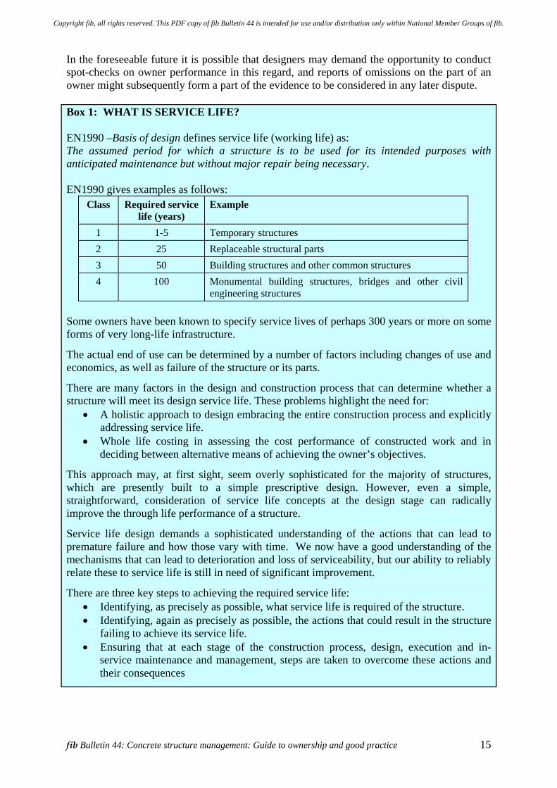
In the foreseeable future it is possible that designers may demand the opportunity to conduct spot-checks on owner performance in this regard, and reports of omissions on the part of an owner might subsequently form a part of the evidence to be considered in any later dispute. Box 1: WHAT IS SERVICE LIFE? EN1990 –Basis of design defines service life (working life) as: The assumed period for which a structure is to be used for its intended purposes with anticipated maintenance but without major repair being necessary. EN1990 gives examples as follows:
Class Required service life (years)
Example
1 1-5 Temporary structures 2 25 Replaceable structural parts 3 50 Building structures and other common structures 4 100 Monumental building structures, bridges and other civil
engineering structures Some owners have been known to specify service lives of perhaps 300 years or more on some forms of very long-life infrastructure.
The actual end of use can be determined by a number of factors including changes of use and economics, as well as failure of the structure or its parts.
There are many factors in the design and construction process that can determine whether a structure will meet its design service life. These problems highlight the need for:
• A holistic approach to design embracing the entire construction process and explicitly addressing service life.
• Whole life costing in assessing the cost performance of constructed work and in deciding between alternative means of achieving the owner’s objectives.
This approach may, at first sight, seem overly sophisticated for the majority of structures, which are presently built to a simple prescriptive design. However, even a simple, straightforward, consideration of service life concepts at the design stage can radically improve the through life performance of a structure.
Service life design demands a sophisticated understanding of the actions that can lead to premature failure and how those vary with time. We now have a good understanding of the mechanisms that can lead to deterioration and loss of serviceability, but our ability to reliably relate these to service life is still in need of significant improvement.
There are three key steps to achieving the required service life: • Identifying, as precisely as possible, what service life is required of the structure. • Identifying, again as precisely as possible, the actions that could result in the structure
failing to achieve its service life. • Ensuring that at each stage of the construction process, design, execution and in-
service maintenance and management, steps are taken to overcome these actions and their consequences
Copyright fib, all rights reserved. This PDF copy of fib Bulletin 44 is intended for use and/or distribution only within National Member Groups of fib.
16 3 Introduction and scope of issues
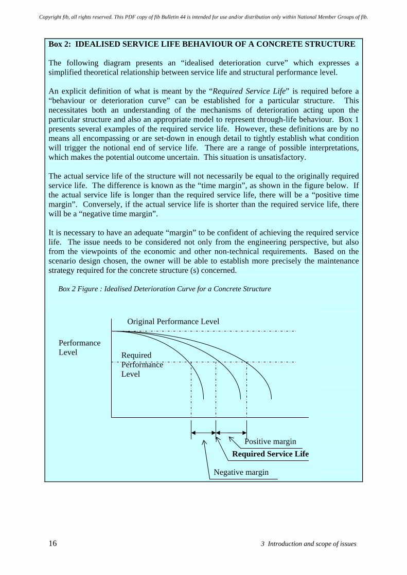
Box 2: IDEALISED SERVICE LIFE BEHAVIOUR OF A CONCRETE STRUCTURE The following diagram presents an “idealised deterioration curve” which expresses a simplified theoretical relationship between service life and structural performance level. An explicit definition of what is meant by the “Required Service Life” is required before a “behaviour or deterioration curve” can be established for a particular structure. This necessitates both an understanding of the mechanisms of deterioration acting upon the particular structure and also an appropriate model to represent through-life behaviour. Box 1 presents several examples of the required service life. However, these definitions are by no means all encompassing or are set-down in enough detail to tightly establish what condition will trigger the notional end of service life. There are a range of possible interpretations, which makes the potential outcome uncertain. This situation is unsatisfactory. The actual service life of the structure will not necessarily be equal to the originally required service life. The difference is known as the “time margin”, as shown in the figure below. If the actual service life is longer than the required service life, there will be a “positive time margin”. Conversely, if the actual service life is shorter than the required service life, there will be a “negative time margin”. It is necessary to have an adequate “margin” to be confident of achieving the required service life. The issue needs to be considered not only from the engineering perspective, but also from the viewpoints of the economic and other non-technical requirements. Based on the scenario design chosen, the owner will be able to establish more precisely the maintenance strategy required for the concrete structure (s) concerned.
Box 2 Figure : Idealised Deterioration Curve for a Concrete Structure
Required Service Life
Performance Level
Original Performance Level
Required Performance Level
Positive margin
Negative margin
Copyright fib, all rights reserved. This PDF copy of fib Bulletin 44 is intended for use and/or distribution only within National Member Groups of fib.
fib Bulletin 44: Concrete structure management: Guide to ownership and good practice 17
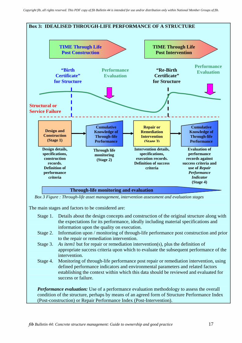
Box 3: IDEALISED THROUGH-LIFE PERFORMANCE OF A STRUCTURE
Box 3 Figure : Through-life asset management, intervention assessment and evaluation stages
The main stages and factors to be considered are:
Stage 1. Details about the design concepts and construction of the original structure along with the expectations for its performance, ideally including material specifications and information upon the quality on execution.
Stage 2. Information upon / monitoring of through-life performance post construction and prior to the repair or remediation intervention.
Stage 3. As item1 but for repair or remediation intervention(s), plus the definition of appropriate success criteria upon which to evaluate the subsequent performance of the intervention.
Stage 4. Monitoring of through-life performance post repair or remediation intervention, using defined performance indicators and environmental parameters and related factors establishing the context within which this data should be reviewed and evaluated for success or failure.
Performance evaluation: Use of a performance evaluation methodology to assess the overall condition of the structure, perhaps by means of an agreed form of Structure Performance Index (Post-construction) or Repair Performance Index (Post-Intervention).
“Birth Certificate”
for Structure
“Re-Birth Certificate”
for Structure
TIME Through Life Post Construction
TIME Through Life Post Intervention
Design and Construction
(Stage 1)
Repair or Remediation Intervention
(Stage 3)
Cumulative Knowledge of Through-life Performance
Cumulative Knowledge of Through-life Performance
Through-life monitoring and evaluation
Design details, specifications, construction
records. Definition of performance
criteria
Intervention details, specifications,
execution records. Definition of success
criteria
Evaluation of performance
records against success criteria and
use of Repair Performance
Indicator (Stage 4)
Performance Evaluation
Structural or Service Failure
Through life monitoring
(Stage 2)
Performance Evaluation
Copyright fib, all rights reserved. This PDF copy of fib Bulletin 44 is intended for use and/or distribution only within National Member Groups of fib.
18 3 Introduction and scope of issues
Carbonation induced corrosion
of a reinforcing bar
Chloride induced corrosion of reinforcing bar –
Note pitting in surface
Marine damage and biological growths
Sulfate / Thaumasite form of attack
Cracking: Alkali-aggregate reaction ?
Cracking : Freeze – thaw action
Figure 8A: Examples of some forms of deterioration affecting concrete structures
Copyright fib, all rights reserved. This PDF copy of fib Bulletin 44 is intended for use and/or distribution only within National Member Groups of fib.
fib Bulletin 44: Concrete structure management: Guide to ownership and good practice 19
Damage and spalling of concrete cover on bridge column - induced by fire effects
Carbonation induced corrosion in bridge soffit
with inadequate cover to bars
Fire damage to bridge beams
Severe impact damage to bridge beams
Reinforcing bars snapped by severe ASR expansion (from Japan)
Damage to pier crosshead by water and freeze-thaw action (note icicles)
Figure 8B: Examples of the effects of some forms of deterioration and accidental actions upon concrete bridges
Copyright fib, all rights reserved. This PDF copy of fib Bulletin 44 is intended for use and/or distribution only within National Member Groups of fib.

Copyright fib, all rights reserved. This PDF copy of fib Bulletin 44 is intended for use and/or distribution only within National Member Groups of fib.
fib Bulletin 44: Concrete structure management: Guide to ownership and good practice 21
4 The owners’ requirements and obligations 4.1 Performance requirements
Society has a number of primary requirements which its structures should fulfil, regardless of whether they are publicly or privately owned. Guidance is typically given through technical codes and standards to ensure a minimum quality of the core structure. The aim is to avoid subjective short-sighted sub-optimisation by the private or public builders and owners. These requirements might include: • To build with appropriate levels of safety. • To build so that it is easily demolished or its use changed at end of the initial use period. • Maintaining a minimum level of safety against global hazards, such as collapse or failure
of the structure or its principal components, and also against local hazards such as falling debris arising from spalled concrete. Standards and expectations in these matters have not developed evenly around the world, reflecting different experiences and concerns.
• Preserving the functionality of the structure by minimising or avoiding interruption to the services provided to society by the structure. For example, taking elements of infrastructure such as bridges, roads, tunnels, harbours etc. out of service temporarily to undertake maintenance or repairs can impose significant disruption and high costs on the users, and thus upon society. These are termed indirect costs.
• Ensuring that an appropriate service life is chosen for the structure at the time of design. There are situations where some structures may have too short a service life, which would be expected to increase the future burden of maintaining and repairing the structure to keep it in service.
NB. Even if a critical structure is privately constructed and owned, in extreme situations society may have to take over the responsibility and costs for its repair and continued satisfactory functioning. However, in such a situation the owner is unlikely to be able to escape his responsibilities, as legal action potentially involving civil and / or criminal proceedings may be instigated against the owner.
• Ensuring that the structure has limited health and environmental impacts during its construction, subsequent use and maintenance.
• Satisfying minimum aesthetic standards for the appearance of the structure. It should be borne in mind that in general structures are composed of a number of elements (e.g. columns, beams, slabs etc), which may be subjected to different local environments and loadings. Thus different parts of the structure may perform differently and can exhibit significant variations in maintenance requirements and life expectancy. Some existing guidance already recognises the distinction between the life-care issues for a structure as a whole and of the elements of which it is comprised. It is also pertinent to recognise that concrete structures may have a variety of other types of components, such as services, fittings, cladding, a drainage system, etc, which each have their own expected service life and that this is usually shorter than that of the main structure. Accordingly any form of management will need to address the life-care issues associated with these elements. The concept of performance specification can be applied throughout the intended life of the structure, starting with the construction process and extending through the period when it is
Copyright fib, all rights reserved. This PDF copy of fib Bulletin 44 is intended for use and/or distribution only within National Member Groups of fib.
22 4 The owners’ requirements and obligations
being maintained to keep it in service. Utilising a supply chain representation, this would imply that: • Owners need to understand and define how the structure and its maintenance help them
fulfil their business goals, together with meeting the needs of users and stakeholders. They also need be able to define and specify clear and reasonable performance requirements for the structure, and to be sufficiently confident that these will be met. This activity would be expected to be undertaken in conjunction with the supporting professional team assembled to achieve these objectives.
• Consulting engineers and others within the supporting professional team need to be able to turn performance requirements into design strategies and engineering specifications, and to assess whether these are being met.
• Contractors and material suppliers need to use the correct materials and processes in a manner that meets the required performance levels.
To achieve a successful outcome, that is meeting the owner’s (better defined) performance requirements, all elements of the supply chain need to work together in a coherent manner. Currently the concepts and procedures for performance specification are still under development. Whereas risk to personnel and risk to the environment are usually regulated by legislation and codes of practice, the economic risk is an issue, which is left to be handled by the owner of the structure. The owner has to decide on specific provisions to be taken to counteract the effect of degradation during the service life and thereby reduce the economical risk associated with future inspections and maintenance. Generally this concerns the balance between first cost and through-life costs.
4.1.1 Reliability and functionality
All owners, public and private, have obligations to society. The scope and nature of the related requirements vary considerably in different countries around the world. In many instances there are specified obligations for regular inspections and assessments necessary to ensure that the requirements for continued structural safety are met. Other requirements in respect of serviceability issues (e.g. deflection, corrosion effects, etc) may be defined in some countries. Special consideration may be needed for certain types of structures, such as those that: • Utilise higher risk structural forms such as cantilevers, very slender columns, vertical
structures with eccentric loads, large spans or thin slabs subject to high punching forces. • Require especially high levels of structural safety due to their function, such as nuclear
power stations, dams, high rise buildings, public arenas where large numbers of people will gather etc.
• Are exposed to a higher than usual risk of accidental loads like fire, explosion, impact, blast, earthquake, etc.
• Have special design requirements, such as fatigue. It is generally accepted that consideration of these matters should use a risk-based approach. Often these matters are evaluated only on a technical basis. It would be sensible, albeit at the risk of making matters somewhat more complicated, that consideration should also be given when appropriate to business and functional / service orientated issues, or other owner requirements and related judgement criteria. These matters are considered further below.
Copyright fib, all rights reserved. This PDF copy of fib Bulletin 44 is intended for use and/or distribution only within National Member Groups of fib.
fib Bulletin 44: Concrete structure management: Guide to ownership and good practice 23
4.2 Responsibilities and liabilities
Although owners and operators of structures will generally have duties under law the exact nature and extent of these duties will vary from one country to another. Typically their responsibility could be to provide and maintain their premises so they do not pose undue risks to the health and safety of their employees, visitors and the public. Failure to discharge the defined duties may give rise to liabilities under criminal or civil law. These requirements may be framed under the provisions of regulations concerning health and safety in the workplace. Whilst a management system for a concrete structure(s) should ensure the safety of those using the structure(s), another important objective of such a system will be to ensure that the actions taken are supporting the business goals and service objectives of the organisation concerned and are helping it manage the risks to which it is exposed. Clearly such a system needs to achieve an appropriate standard of care to meet good practice requirements. Special consideration may be needed for certain types of structures, such as those that: • Have minimal structural redundancy – such as some forms of grandstand • Attract large numbers of people or are particularly tall • Exist in an aggressive environment • Fall outside the scope of verified code methodologies or use innovative materials or
design • Were designed to now outdated codes or components of these that are now recognised as
being not sufficiently conservative Special procedures may also be required to achieve a durable structure, whose performance is adequate for the required service life period. Previously in Section 3.3 the limitations of the general durability related provisions in design codes and standards were noted. Consideration needs to be given to the respective roles and responsibilities of the various parties contributing to the processes involved. Designers generally acknowledge that they have a professional duty of care to consider the implications of their design decisions upon the life span performance of the facility. In many countries this duty is supplemented by parallel statutory responsibilities arising from health and safety and related regulations. For example the new Eurocode EN 1990 – Basis of Structural Design sets out some critical assumptions applicable to all structures designed within its remit. These include requirements for: • Adequate supervision and quality control during construction. • Use of construction materials and products that comply with Eurocode stipulations. • Use of the structure in accordance with the design assumptions. • Adequate maintenance. Currently in many situations these requirements are not being met, except perhaps upon major construction projects involving the largest structures. Positive actions are needed to address these requirements, which might include: • Specific provision for undertaking inspections and maintenance works. • Consideration of the sensitivity of the structure to the effects of deterioration (see below).
Copyright fib, all rights reserved. This PDF copy of fib Bulletin 44 is intended for use and/or distribution only within National Member Groups of fib.
24 4 The owners’ requirements and obligations
• Measures to achieve resistance to the envisaged deterioration processes, or to take steps to design them out as far as that may be possible (e.g. use of stainless steel reinforcement to avoid the possibility of reinforcement corrosion).
EN 1990 also identifies that a suitable quality management system is required to address organisational matters, the definition of the reliability requirements and to ensure that there are appropriate controls during design, execution and throughout use, including maintenance. Current codes commonly contain similar, but less emphatic, assumptions. It should also be noted that current design codes, including the Eurocodes, make the fundamental assumption that the facility concerned will not experience deterioration during its lifespan (refer Boxes 1 and 2). Thus whilst issues of life safety are, for most potential failure modes, addressed by achieving compliance with code provisions for the design of new structures; consideration of the effects of deterioration have to be quantified separately using the limited relevant guidance currently available. For example, the risks arising from issues such as spalling of concrete due to corrosion of reinforcing bars would need to be evaluated and compared with specific acceptance criteria given by the owner. Similarly no code currently exists for the evaluation of hazards to the environment from particular construction or in-service activities, or what might constitute an acceptable level of risk for particular hazard scenarios. Again this would need to be assessed specifically for each individual structure. In practice these issues are most likely to relate to the choice of materials and methods of implementation of these activities. The acceptability of a structure with regard to durability is most often directly linked to the costs and timing of future maintenance and repair works. These costs will depend on the future deterioration of the structure but also on the specific strategies and policies the owner adopts for through-life management of the structure. As these matters are essentially economic in nature they are left to the preferences of the individual owners, as long as compliance with life-safety and related requirements continue to be met. Other non-technical requirements and influencing factors are discussed in the following Sections of the report. It should also be recognised that in some countries there is legislation which does place a direct responsibility upon owners in respect of the performance of their buildings and assets during their lifespan. For example, in Europe there is a requirement which relates to the structural “stability and solidity” of buildings and other facilities, which has been implemented primarily through health and safety legislation concerned with the places of work (so called workplace regulations). Over time such regulations and requirements are expected to impose wider duties and obligations upon owners. These obligations may in time be extended more widely than the workplace The severe weather experienced in November 2005 produced conditions under which a number of buildings collapsed, causing an appreciable number of fatalities and injuries. These experiences have shown that an improved approach is needed to ensure that appropriate through-life management, care and maintenance is provided to existing structures and buildings. It has been estimated that maintenance / through-life care expenditure should be between 1.5% and 2 % per year of the cost of construction. The German experiences and their response to them are discussed in Box 4.
Copyright fib, all rights reserved. This PDF copy of fib Bulletin 44 is intended for use and/or distribution only within National Member Groups of fib.
fib Bulletin 44: Concrete structure management: Guide to ownership and good practice 25
Also of interest are the particular issues concerning cladding to buildings, which create other obligations that impose duties upon owners. These are discussed in Box 5. Box 4: GERMAN OBSERVATIONS UPON THE MANAGEMENT OF BUILDINGS Although the severe weather experienced in November 2005 produced significant snow loading in many parts of Europe, these were generally less than the design imposed load. Under these conditions a number of buildings collapsed, including the widely reported events at the ice pavilion in Bad Reichenhall, Germany. Unfortunately these events created an appreciable number of fatalities and injuries amongst people using the various facilities concerned. At the time these events were widely reported in both the technical and general press. Investigations undertaken into the structural failures have produced a number of observations which are applicable to a number of types of structure and circumstances of ownership. Importantly the studies showed that the lack of through-life management, care and maintenance contributed to the circumstances leading to the various failures and collapses.
Following these experiences the Bavarian federal state in Germany prepared recommendations for the supervision, inspection and checking of the structural integrity of existing buildings. Guidance is also given on the duties of owners. These concern:
• requirements for the minimum documentation to be supplied with the building, • the conceptual and structural design of the building, • classification of building type and potential associated risks, • the condition of the building, • changes in through-life building scope and function, as well as new build additions, • definition of an inspection regime, together with cycles and inspection requirements, • recommendations on how inspections should be undertaken, • requirements for the professional standing and background of the inspector, and • recommendations on assessment of innovative structures and structural elements.
This new guidance defines the safety goals to be achieved by regular inspection. The technical detail needed to underpin this process is being developed by the Association of German Engineers as guidance document No. 6200. National efforts have been started under the auspices of the Ministry of Construction.
With the publication of this guidance the legal obligations for German building owners will change. They will have a duty to engage a qualified professional (engineer) in the assessment procedure. A three-tier inspection system is being suggested, with a 10 yearly inspection being undertaken by a qualified structural checking engineer. An important point to note is that the checking person will have to be qualified in their own right. Thus under these rules the 10 year inspection / review could not be undertaken by an unqualified person working in the checking engineer's office.
The recent events have shown that such an approach is needed to ensure that appropriate through-life management, care and maintenance is provided to existing structures and buildings. However, it is very difficult to evaluate the economic implications of this. It has been estimated that maintenance / through-life care expenditure should be between 1.5% and 2 % per year of the cost of construction. This underlines the need for superior quality planning, design, execution and maintenance of structures and buildings. It also emphasises the important responsibilities carried by the engineering profession in this regard.
Copyright fib, all rights reserved. This PDF copy of fib Bulletin 44 is intended for use and/or distribution only within National Member Groups of fib.
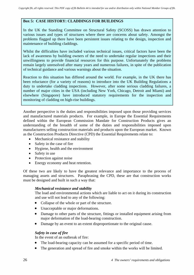
26 4 The owners’ requirements and obligations
Box 5: CASE HISTORY: CLADDINGS FOR BUILDINGS In the UK the Standing Committee on Structural Safety (SCOSS) has drawn attention to various issues and types of structures where there are concerns about safety. Amongst the problems flagged up there have been persistent issues relating to the design, inspection and maintenance of building claddings.
Whilst the difficulties have included various technical issues, critical factors have been the lack of awareness by building owners of the need to undertake regular inspections and their unwillingness to provide financial resources for this purpose. Unfortunately the problems remain largely unresolved after many years and numerous failures, in spite of the publication of technical guidance and various warnings about the situation.
Reaction to this situation has differed around the world. For example, in the UK there has been reluctance (for a variety of reasons) to introduce into the UK Building Regulations a duty to undertake cladding inspections. However, after some serious cladding failures, a number of major cities in the USA (including New York, Chicago, Detroit and Miami) and elsewhere (Singapore) have introduced statutory requirements for the inspection and monitoring of cladding on high-rise buildings.
Another perspective is the duties and responsibilities imposed upon those providing services and manufactured materials products. For example, in Europe the Essential Requirements defined within the European Commission Mandate for Construction Products gives an understanding of the breadth of some of the duties and responsibilities imposed upon manufacturers selling construction materials and products upon the European market. Known as the Construction Products Directive (CPD) the Essential Requirements relate to:
• Mechanical resistance and stability • Safety in the case of fire • Hygiene, health and the environment • Safety in use • Protection against noise • Energy economy and heat retention.
Of these two are likely to have the greatest relevance and importance to the process of managing assets and structures. Paraphrasing the CPD, these are that construction works must be designed and built in such a way that:
Mechanical resistance and stability The load and environmental actions which are liable to act on it during its construction and use will not lead to any of the following: • Collapse of the whole or part of the structure. • Unacceptable or major deformations. • Damage to other parts of the structure, fittings or installed equipment arising from
major deformation of the load-bearing construction. • Damage by an event to an extent disproportionate to the original cause. Safety in case of fire In the event of an outbreak of fire: • The load-bearing capacity can be assumed for a specific period of time. • The generation and spread of fire and smoke within the works will be limited.
Copyright fib, all rights reserved. This PDF copy of fib Bulletin 44 is intended for use and/or distribution only within National Member Groups of fib.
fib Bulletin 44: Concrete structure management: Guide to ownership and good practice 27
• The spread of the fire to neighbouring structures will be limited. • Occupants can leave the structure or be rescued by other means. • The safety of rescue teams is taken into consideration.
Thus it is critical that the overall assessment, maintenance and repair process for a concrete structure(s) highlights the responsibilities held by the different parties involved. For example: • The owner is responsible for ensuring that a life-care plan is developed and implemented
for the structure. • The owner should state his requirements for the structure after intervention, such as
• the required remaining service life and the corresponding performance criteria • the need for upgrading of the structure if an improvement or a modernisation
coupled with the intervention is found necessary during the inspection and assessment process
• the desire for an improved aesthetic appearance. • The engineer in conjunction with others in the professional team will assess the quality,
the present condition and the estimated remaining service life of the structure if it is left without maintenance or repair, and assuming unchanged or a defined future use of the structure. It may also be appropriate to consider the potential effects of envisaged future climate change.
• The engineer in conjunction with others in the professional team will evaluate the ability of alternative interventions (maintenance procedures or repair methods) to provide the required short and long term performance. He will estimate the initial costs, the time dependent costs and the overall remaining service life costs, based on the specific conditions of the owner (public or private), as well as those of possible alternative solutions. He will describe the reliability and specific consequences of each method regarding future need for maintenance and re-repair actions.
• The owner must select his preferred solution. Clarity is essential in these roles and in the corresponding responsibilities of the different parties involved. Although the engineer, together with other members of the professional team, should make his recommendations taking the overall scene into consideration to the extent he can, the owner should take the final decisions. The owner should define the quality he wants, he should take steps to ensure that he gets what he has defined, and he should be prepared to pay the costs of achieving this quality. So far the above discussions have mainly focused upon issues relating to the functional requirements for the asset or structure. However there are other wider economic, socio-cultural and environmental factors (non-technical factors or issues) that may have an important bearing upon decisions for managing the asset concerned. Clearly management decisions need to be undertaken in a holistic way, balancing these different considerations. It is necessary to do this within a suitably broad framework. Previous work relating to life-cycle analysis of assets and structures has provided various frameworks. Figure 9 illustrates the classification of components which is used in this document. These are considered in the following sections, which address: • Economic and financial requirements • Societal and cultural aspects • Environmental considerations
Copyright fib, all rights reserved. This PDF copy of fib Bulletin 44 is intended for use and/or distribution only within National Member Groups of fib.
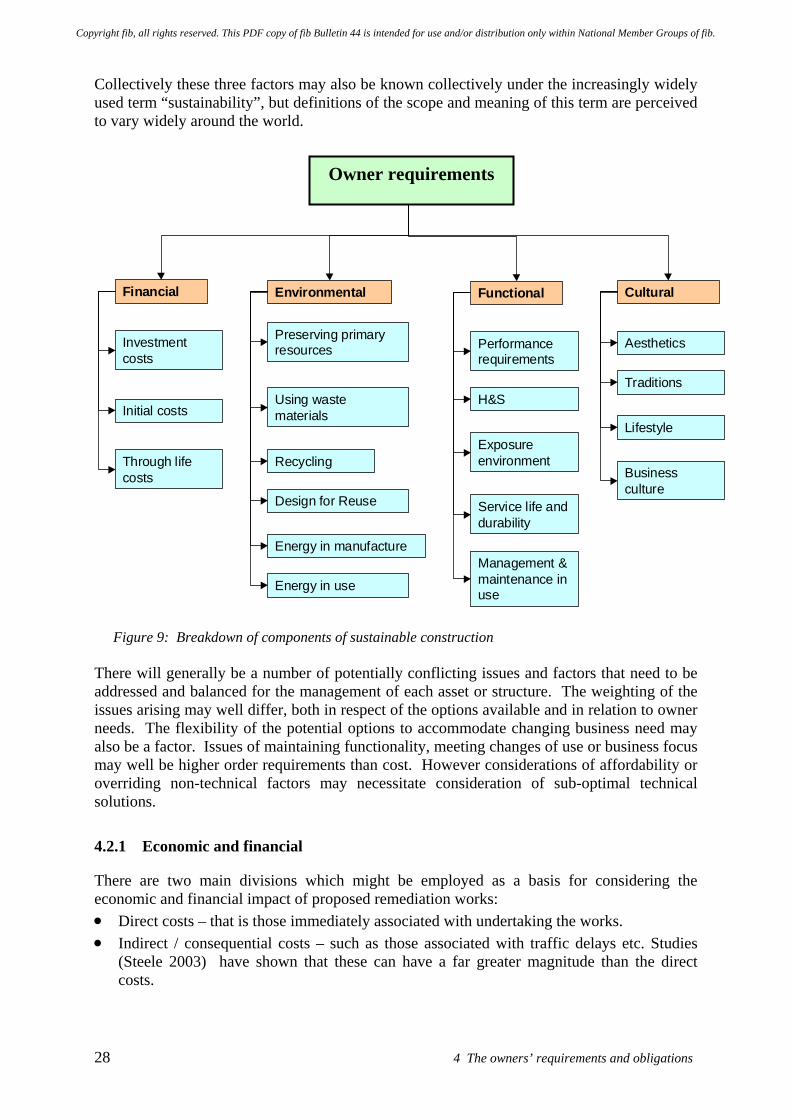
28 4 The owners’ requirements and obligations
Collectively these three factors may also be known collectively under the increasingly widely used term “sustainability”, but definitions of the scope and meaning of this term are perceived to vary widely around the world.
Client’s requirements
Financial Cultural
Investmentcosts
Initial costs
Through lifecosts
Environmental
Preserving primaryresources
Using wastematerials
Recycling
Design for Reuse
Energy in manufacture
Energy in use
Functional
Performancerequirements
Exposureenvironment
Service life anddurability
H&S
Management &maintenance inuse
Aesthetics
Traditions
Lifestyle
Businessculture
Figure 9: Breakdown of components of sustainable construction There will generally be a number of potentially conflicting issues and factors that need to be addressed and balanced for the management of each asset or structure. The weighting of the issues arising may well differ, both in respect of the options available and in relation to owner needs. The flexibility of the potential options to accommodate changing business need may also be a factor. Issues of maintaining functionality, meeting changes of use or business focus may well be higher order requirements than cost. However considerations of affordability or overriding non-technical factors may necessitate consideration of sub-optimal technical solutions.
4.2.1 Economic and financial
There are two main divisions which might be employed as a basis for considering the economic and financial impact of proposed remediation works: • Direct costs – that is those immediately associated with undertaking the works. • Indirect / consequential costs – such as those associated with traffic delays etc. Studies
(Steele 2003) have shown that these can have a far greater magnitude than the direct costs.
Owner requirements
Copyright fib, all rights reserved. This PDF copy of fib Bulletin 44 is intended for use and/or distribution only within National Member Groups of fib.
fib Bulletin 44: Concrete structure management: Guide to ownership and good practice 29
Costs can be evaluated on a variety of bases. The recommended approach, which is now finding much wider acceptance, is whole (remaining) life costing for a particular structure or inventory of structures. Clearly many owners will seek to manage their concrete structures so that they are operated and maintained at minimum cost. However if they are able to take a wider view, they may seek to manage them in a way that delivers best overall value. The way this is done will depend on how best value criteria are defined and measured. Amongst other factors, consideration might include the value of the structure, that is its direct financial worth and the contribution it makes to the owner’s business goals and processes.
4.2.2 Societal and cultural aspects
When seeking to make an evaluation of societal and cultural issues there are several levels that this can be undertaken at. For example this could be on the basis of anticipated effects upon: • Community: urban and rural environments
Government policies (national, regional and local scales) Transport impacts Employment Aesthetics Political philosophy Health and safety obligations Lifestyle preferences Media and Press Public perception and confidence Consultation and approval processes Heritage and culture
• Working environment
Building and work traditions Health and safety obligations Legal obligations Business culture and ability of business to endure / survive and prosper Reputation Training, education and personnel development Trade unionisation / organisation of labour
There may also be implications arising from the ownership of the structure / facility and the functional objectives for it. For example, there can be a significant difference between the owners’ obligations for public and private structures. Take the situation of a public road authority which is responsible for components of national infrastructure, it has obligations not only in terms of the safety of users and the public, but also to ensure mobility and to minimise delay to travellers. Closing down roads for repair works or other reasons is extremely costly, not only in terms of direct costs but also in terms of consequential and indirect costs. Particular consideration has to be given to responsibilities associated with health and safety issues. Construction, remediation and related work must be undertaken in such a way that it will not be a threat to the hygiene or health of the workers, users, occupants or neighbours of the facility. There are specific concerns in relation to emissions to the environment, such as solid or liquid wastes, smoke, radiation, as well as the presence of dangerous particles, gases etc released to the atmosphere or the water environment.
Copyright fib, all rights reserved. This PDF copy of fib Bulletin 44 is intended for use and/or distribution only within National Member Groups of fib.
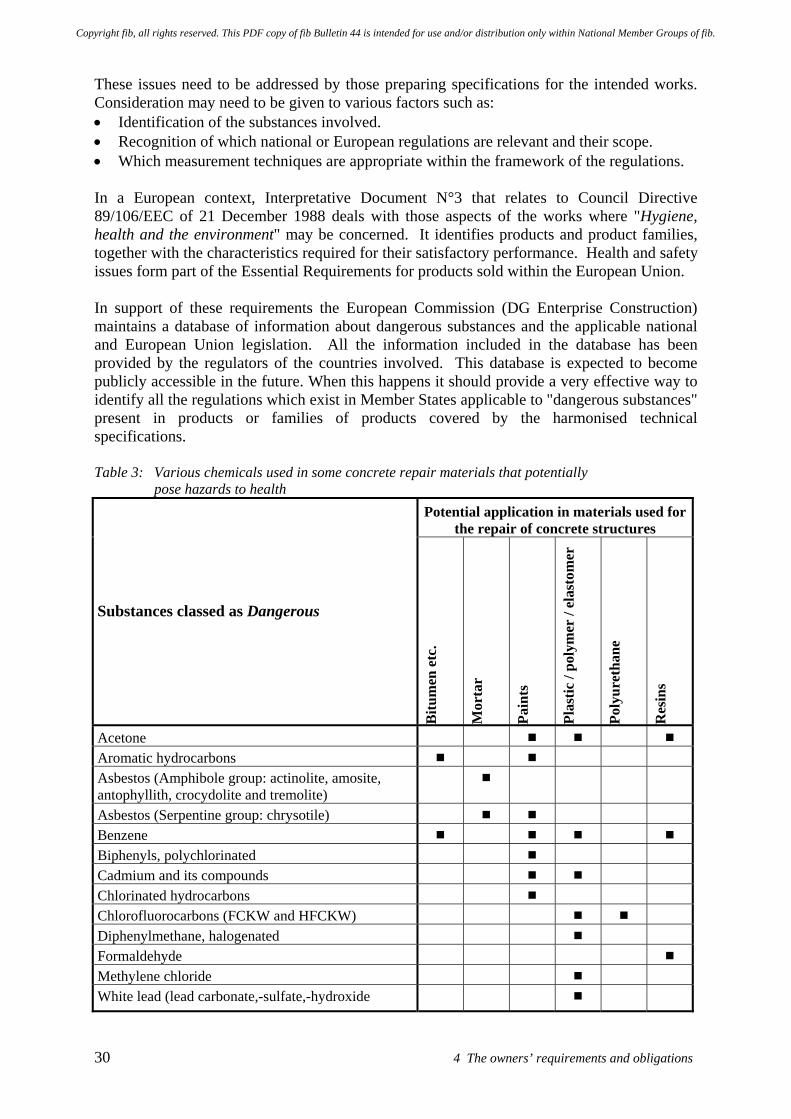
30 4 The owners’ requirements and obligations
These issues need to be addressed by those preparing specifications for the intended works. Consideration may need to be given to various factors such as: • Identification of the substances involved. • Recognition of which national or European regulations are relevant and their scope. • Which measurement techniques are appropriate within the framework of the regulations. In a European context, Interpretative Document N°3 that relates to Council Directive 89/106/EEC of 21 December 1988 deals with those aspects of the works where "Hygiene, health and the environment" may be concerned. It identifies products and product families, together with the characteristics required for their satisfactory performance. Health and safety issues form part of the Essential Requirements for products sold within the European Union. In support of these requirements the European Commission (DG Enterprise Construction) maintains a database of information about dangerous substances and the applicable national and European Union legislation. All the information included in the database has been provided by the regulators of the countries involved. This database is expected to become publicly accessible in the future. When this happens it should provide a very effective way to identify all the regulations which exist in Member States applicable to "dangerous substances" present in products or families of products covered by the harmonised technical specifications. Table 3: Various chemicals used in some concrete repair materials that potentially
pose hazards to health Potential application in materials used for
the repair of concrete structures
Substances classed as Dangerous
Bitu
men
etc
.
Mor
tar
Pain
ts
Plas
tic /
poly
mer
/ el
asto
mer
Poly
uret
hane
Res
ins
Acetone Aromatic hydrocarbons Asbestos (Amphibole group: actinolite, amosite, antophyllith, crocydolite and tremolite)
Asbestos (Serpentine group: chrysotile) Benzene Biphenyls, polychlorinated Cadmium and its compounds Chlorinated hydrocarbons Chlorofluorocarbons (FCKW and HFCKW) Diphenylmethane, halogenated Formaldehyde Methylene chloride White lead (lead carbonate,-sulfate,-hydroxide
Copyright fib, all rights reserved. This PDF copy of fib Bulletin 44 is intended for use and/or distribution only within National Member Groups of fib.
fib Bulletin 44: Concrete structure management: Guide to ownership and good practice 31
Table 3 provides a brief overview of dangerous substances which could pose a hazard to human health and may be present within concrete repair materials or products. Clearly materials and products containing such substances need to be handled with considerable care and in accordance with the requirements of the relevant health and safety legislation. Further details of dangerous substances used more generally in construction industry materials and products are also given in various national and European regulations. Those seeking further information may find the Austrian national regulations a good starting point if they are unable to find appropriate national guidance.
4.2.3 Environmental
As with economic and financial evaluations, there are two main divisions which might be employed as a basis for considering the environmental impact of proposed remediation works: • Direct impacts – that is those associated with the materials used and wastes produced /
emissions to the environment (atmosphere, water, noise etc) etc during the works. • Indirect / consequential impacts – such as those associated with traffic delays etc. Studies
(Steele 2003) have shown that these can have a far greater magnitude than the direct impacts.
When seeking to make an evaluation of environmental impact there are several levels that this can be undertaken at. For example, this could be on the basis of anticipated effects upon: • Global issues (Climate change, acid deposition, ozone depletion, toxic air pollution, fossil
fuel depletion, marine environment pollution, habitat and ecosystems) Preserving primary resources
• Local and site issues for the built and rural environment Use of natural resources Wastes - minimisation, recycling and re-use and disposal Energy – employed during manufacture and when in use Emissions to environment (atmosphere, water, noise etc) Natural habitats and ecosystems Life cycle analysis
• Internal environment within structure / facility Health Comfort
These will not all be appropriate to a particular structure or remediation process. Clearly it would be difficult or impractical to make appropriate assessments without a general consensual framework providing a process to make the required evaluation. Work has been carried out in the UK by BRE (Dickie and Howard 2000) to assess the environmental impact of different construction options and to enable these to be compared on the basis of single scale score. To do this the relative importance of different environmental factors, along with related economic and social factors, are taken into account by the use of weighting factors. In the BRE system this produces an overall ECOPOINTS score, enabling comparisons and judgements to be made. Work is being carried out to extend the system to repair, refurbishment and remediation activities. Other workers are no doubt developing other systems and procedures for evaluation, option comparison and selection.
Copyright fib, all rights reserved. This PDF copy of fib Bulletin 44 is intended for use and/or distribution only within National Member Groups of fib.
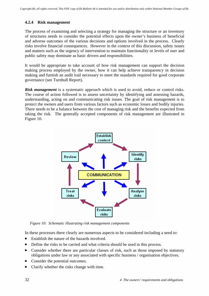
32 4 The owners’ requirements and obligations
4.2.4 Risk management
The process of examining and selecting a strategy for managing the structure or an inventory of structures needs to consider the potential effects upon the owner’s business of beneficial and adverse outcomes of the various decisions and options involved in the process. Clearly risks involve financial consequences. However in the context of this discussion, safety issues and matters such as the urgency of intervention to maintain functionality or levels of user and public safety may dominate as basic drivers and responsibilities. It would be appropriate to take account of how risk management can support the decision making process employed by the owner, how it can help achieve transparency in decision making and furnish an audit trail necessary to meet the standards required for good corporate governance (see Turnbull Report). Risk management is a systematic approach which is used to avoid, reduce or control risks. The course of action followed is to assess uncertainty by identifying and assessing hazards, understanding, acting on and communicating risk issues. The goal of risk management is to protect the owners and users from various factors such as economic losses and bodily injuries. There needs to be a balance between the cost of managing risk and the benefits expected from taking the risk. The generally accepted components of risk management are illustrated in Figure 10.
Figure 10: Schematic illustrating risk management components
In these processes there clearly are numerous aspects to be considered including a need to: • Establish the nature of the hazards involved. • Define the risks to be carried and what criteria should be used in this process. • Consider whether there are particular classes of risk, such as those imposed by statutory
obligations under law or any associated with specific business / organisation objectives. • Consider the potential outcomes. • Clarify whether the risks change with time.
Copyright fib, all rights reserved. This PDF copy of fib Bulletin 44 is intended for use and/or distribution only within National Member Groups of fib.
fib Bulletin 44: Concrete structure management: Guide to ownership and good practice 33
• Identify the internal and external stakeholders involved. • Establish what hazard scenarios should be considered. • Clarify when a risk should be controlled or reduced and how can this be done. Once a hazard has been identified and quantified in some manner, the decision has to be made whether the associated risk can be accepted or not. If risks are considered to be too large for direct acceptance, the standard approach is to look for adequate counter measures. When planning counter measures, it is first necessary to recognise possible hazards. The aim is to detect those events or processes where a significant benefit can be obtained from a proportionally small input effort. Possible countermeasures can be technical or administrative and can fall within the following strategies: • Avoid the risk by changing the concept or the objectives. • Reduce the cause of the risk. • Control the risks by using suitable alarm systems, vigilance, inspections, etc. • Overcome the risks by providing adequate strength or capacity for the worst credible
loading or performance requirement. It is widely recognised that risks in civil engineering projects can be substantial. Exposures above the anticipated profit margin are not an exception for the contractor or for members of the professional team. Management of risks is therefore a key point of attention for all concerned. Generally no single party is able to satisfactorily handle substantial project risks. In such circumstances it is has been suggested that additional investigations / engineering appraisals and development work should be undertaken until risk exposure is reduced to about 3% - 5% of the anticipated project cost. Ownership of particular risks needs to be identified in advance. A risk management process is likely to include the following main activities: • Undertake identification of possible hazards and seek to characterise and quantify them by
means of risk analysis methods. Risks may be differentiated on the basis of whether they impact upon the construction phase or on the through-life performance of the asset, with attendant financial and other implications.
• Record significant risks in a risk file / dossier. • Establish which risks might be avoided or reduced, and whether the other risks can be
adequately controlled or overcome by management processes. • Preparation of a project quality management plan, including subsequent review and
adjustment during the progress of the works - refer Section 8.4.4. With a properly developed awareness of the potential sources of risk, assessment of risk exposure is feasible by various forms of analysis. Such analyses can be performed at different levels of detail. In the early stages of a project the available approaches include: • Standard percentage of construction cost. This type of analysis can only be applied if
there is an extensive track record for the concept / process concerned and if experience shows that actual risk exposure levels are reasonably consistent between projects.
• Risk inventory lists (RIL). The use of RIL makes risk analysis more project specific. All disciplines concerned should contribute to the development of the RIL, which can provide a powerful tool to focus on risk issues, to improve awareness and to get an overview of risk exposure. Such overview is a pre-requisite to allow management of risks. The information
Copyright fib, all rights reserved. This PDF copy of fib Bulletin 44 is intended for use and/or distribution only within National Member Groups of fib.
34 4 The owners’ requirements and obligations
contributes to the development of an overall risk dossier (perhaps also known as the project risk file).
• Risk inventory list together with Monte Carlo simulations. This approach may be selected for schemes which are exposed to substantial risks. Both size and characteristics of the project need to be considered to decide if this type of analysis is appropriate. Large design / construct projects or smaller projects but with multi disciplinary input are more likely to benefit from this type of analysis.
During the detailed design and construction phases of large or complicated projects, a practical approach can be to focus upon assessing risk exposure and its subsequent management by the following means: • Top XX list: A shortlist of risks is compiled from an overall risk analysis in order to
identify the issues which dominant the overall exposure to risk. The advantage of a shortlist is that it enables attention to be focused upon the risks which are of the greatest concern and accordingly should receive the greatest attention.
• Update of the risk dossier: During detailed design and execution of the works the overall perception of risks may change as more detail and understanding becomes available or activities are completed without incident. Updating the file keeps attention focused on the issues that should be of the greatest concern.
• Quality control and quality assurance (QA and QC): Generally QA and QC is delivered through a Project Quality Plan - refer Section 8.4.4.
• The presence of an appropriate qualified and experienced site engineer / team: Although information contained in contracts, specifications, drawings, instructions, procedures and work plans should be adequate to allow proper execution of the works, it should be realised that civil engineering projects generally have a high degree of complexity and typically have a relative low degree of overall repetition. Whilst verification should (through supervision and checking procedures) minimise the occurrence of non-conformances, there can be significant benefits to be gained from having the relevant engineering discipline available on site to give support to construction and to help recognise the potential for non- conformances at an early stage.
Risk assessment for activities in the design and construction phases needs to reflect the particular tasks being analysed and the wider circumstances which might exist. Accordingly each is situation specific and only the broad principles of the approaches to be employed can be described in a guidance document such as this. Appendix E presents further information making risk assessment for the planned life cycle of the system under consideration, including details upon categories for the classification of: • the frequency / probability of occurrence of the hazardous situation • the severity / consequence of the worst possible outcome arising from the hazard Appendix E examines means of profiling and characterisation of the risks likely to be encountered. A template is presented for the assessment of risk arising from the current situation and those arising from possible corrective actions. The outcomes are then mapped back onto the risk matrix to assess their acceptability. Cost- benefit analysis may also be carried out to help evaluate the alternative options, especially when the magnitude of the costs and the risks involved is sufficiently large.
Copyright fib, all rights reserved. This PDF copy of fib Bulletin 44 is intended for use and/or distribution only within National Member Groups of fib.
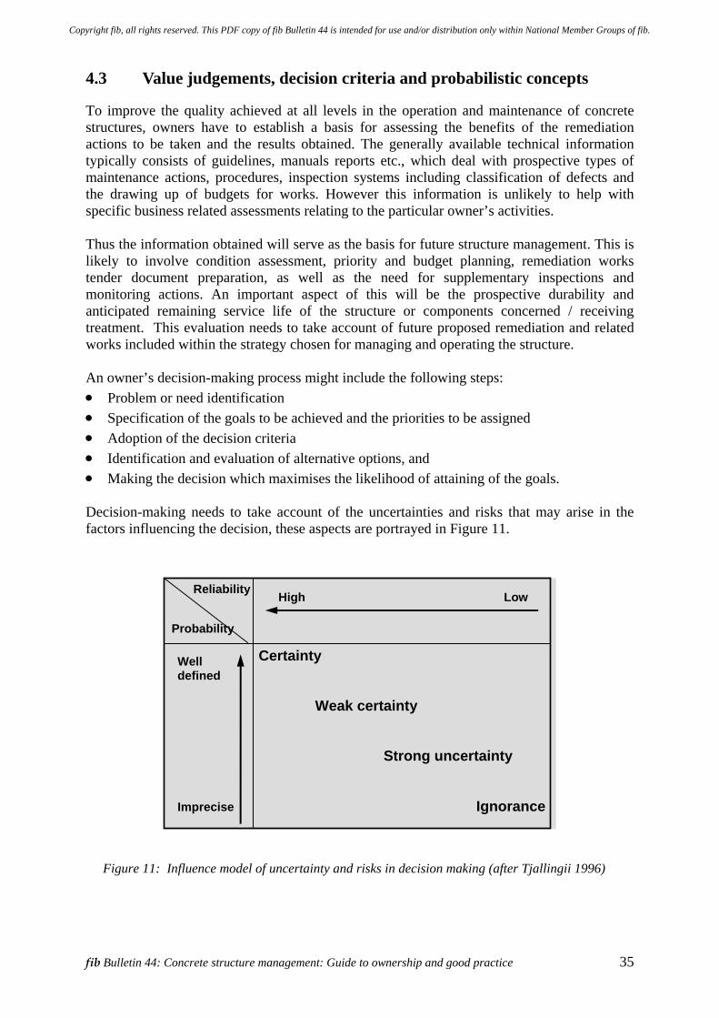
fib Bulletin 44: Concrete structure management: Guide to ownership and good practice 35
4.3 Value judgements, decision criteria and probabilistic concepts
To improve the quality achieved at all levels in the operation and maintenance of concrete structures, owners have to establish a basis for assessing the benefits of the remediation actions to be taken and the results obtained. The generally available technical information typically consists of guidelines, manuals reports etc., which deal with prospective types of maintenance actions, procedures, inspection systems including classification of defects and the drawing up of budgets for works. However this information is unlikely to help with specific business related assessments relating to the particular owner’s activities. Thus the information obtained will serve as the basis for future structure management. This is likely to involve condition assessment, priority and budget planning, remediation works tender document preparation, as well as the need for supplementary inspections and monitoring actions. An important aspect of this will be the prospective durability and anticipated remaining service life of the structure or components concerned / receiving treatment. This evaluation needs to take account of future proposed remediation and related works included within the strategy chosen for managing and operating the structure. An owner’s decision-making process might include the following steps: • Problem or need identification • Specification of the goals to be achieved and the priorities to be assigned • Adoption of the decision criteria • Identification and evaluation of alternative options, and • Making the decision which maximises the likelihood of attaining of the goals. Decision-making needs to take account of the uncertainties and risks that may arise in the factors influencing the decision, these aspects are portrayed in Figure 11.
Figure 11: Influence model of uncertainty and risks in decision making (after Tjallingii 1996)
Reliability
Probability
Well defined
Imprecise
High Low
Certainty Weak certainty Strong uncertainty Ignorance
Copyright fib, all rights reserved. This PDF copy of fib Bulletin 44 is intended for use and/or distribution only within National Member Groups of fib.
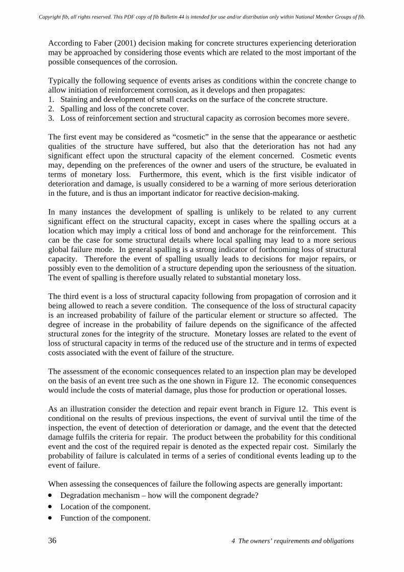
36 4 The owners’ requirements and obligations
According to Faber (2001) decision making for concrete structures experiencing deterioration may be approached by considering those events which are related to the most important of the possible consequences of the corrosion. Typically the following sequence of events arises as conditions within the concrete change to allow initiation of reinforcement corrosion, as it develops and then propagates: 1. Staining and development of small cracks on the surface of the concrete structure. 2. Spalling and loss of the concrete cover. 3. Loss of reinforcement section and structural capacity as corrosion becomes more severe. The first event may be considered as “cosmetic” in the sense that the appearance or aesthetic qualities of the structure have suffered, but also that the deterioration has not had any significant effect upon the structural capacity of the element concerned. Cosmetic events may, depending on the preferences of the owner and users of the structure, be evaluated in terms of monetary loss. Furthermore, this event, which is the first visible indicator of deterioration and damage, is usually considered to be a warning of more serious deterioration in the future, and is thus an important indicator for reactive decision-making. In many instances the development of spalling is unlikely to be related to any current significant effect on the structural capacity, except in cases where the spalling occurs at a location which may imply a critical loss of bond and anchorage for the reinforcement. This can be the case for some structural details where local spalling may lead to a more serious global failure mode. In general spalling is a strong indicator of forthcoming loss of structural capacity. Therefore the event of spalling usually leads to decisions for major repairs, or possibly even to the demolition of a structure depending upon the seriousness of the situation. The event of spalling is therefore usually related to substantial monetary loss. The third event is a loss of structural capacity following from propagation of corrosion and it being allowed to reach a severe condition. The consequence of the loss of structural capacity is an increased probability of failure of the particular element or structure so affected. The degree of increase in the probability of failure depends on the significance of the affected structural zones for the integrity of the structure. Monetary losses are related to the event of loss of structural capacity in terms of the reduced use of the structure and in terms of expected costs associated with the event of failure of the structure. The assessment of the economic consequences related to an inspection plan may be developed on the basis of an event tree such as the one shown in Figure 12. The economic consequences would include the costs of material damage, plus those for production or operational losses. As an illustration consider the detection and repair event branch in Figure 12. This event is conditional on the results of previous inspections, the event of survival until the time of the inspection, the event of detection of deterioration or damage, and the event that the detected damage fulfils the criteria for repair. The product between the probability for this conditional event and the cost of the required repair is denoted as the expected repair cost. Similarly the probability of failure is calculated in terms of a series of conditional events leading up to the event of failure. When assessing the consequences of failure the following aspects are generally important: • Degradation mechanism – how will the component degrade? • Location of the component. • Function of the component.
Copyright fib, all rights reserved. This PDF copy of fib Bulletin 44 is intended for use and/or distribution only within National Member Groups of fib.
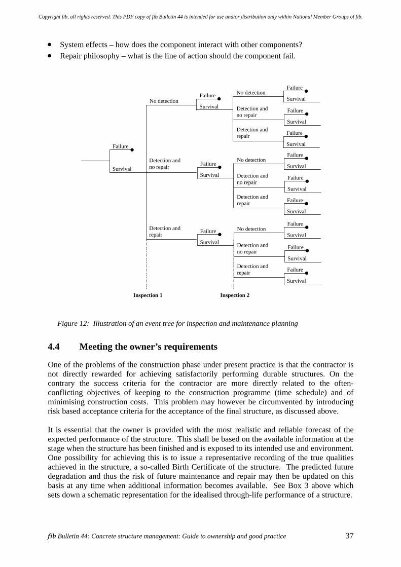
fib Bulletin 44: Concrete structure management: Guide to ownership and good practice 37
• System effects – how does the component interact with other components? • Repair philosophy – what is the line of action should the component fail.
Failure
Survival
No detection
Detection andno repair
Detection andrepair
Failure
Survival
No detection
Detection andno repair
Detection andrepair
Failure
Survival
Failure
Survival
Failure
Survival
Failure
Survival
Failure
Survival
No detection
Detection andno repair
Detection andrepair
Failure
Survival
Failure
Survival
Failure
Survival
No detection
Detection andno repair
Detection andrepair
Failure
Survival
Failure
Survival
Failure
Survival
Inspection 1 Inspection 2
Figure 12: Illustration of an event tree for inspection and maintenance planning
4.4 Meeting the owner’s requirements
One of the problems of the construction phase under present practice is that the contractor is not directly rewarded for achieving satisfactorily performing durable structures. On the contrary the success criteria for the contractor are more directly related to the often-conflicting objectives of keeping to the construction programme (time schedule) and of minimising construction costs. This problem may however be circumvented by introducing risk based acceptance criteria for the acceptance of the final structure, as discussed above. It is essential that the owner is provided with the most realistic and reliable forecast of the expected performance of the structure. This shall be based on the available information at the stage when the structure has been finished and is exposed to its intended use and environment. One possibility for achieving this is to issue a representative recording of the true qualities achieved in the structure, a so-called Birth Certificate of the structure. The predicted future degradation and thus the risk of future maintenance and repair may then be updated on this basis at any time when additional information becomes available. See Box 3 above which sets down a schematic representation for the idealised through-life performance of a structure.
Copyright fib, all rights reserved. This PDF copy of fib Bulletin 44 is intended for use and/or distribution only within National Member Groups of fib.
38 4 The owners’ requirements and obligations
At the end of the liability period the Birth Certificate may be updated on the basis of the results of a test program defined as part of the contractual basis. If the updated estimate of the need for maintenance and intervention works complies with the requirements stated in the contract the contractor may be released from his liability. If on the other hand this is not the case the action taken could be the provision of additional protective measures such as coatings, membranes, cathodic protection or similar, to provide the (contractually) acceptable level of risk to the owner. It is important to recognise that a concrete structure is generally “silent” about how environmental processes and developing deterioration are affecting it. These may not be apparent to observers until deterioration has become advanced and mid- or later-stage damage (such as cracking and spalling) has occurred, which have visible manifestations. This is because the environmental mechanisms involved typically work by slowly altering the internal physico-chemical environment within the surface (cover) zone of the concrete, potentially over periods of years or even decades, which then permits deterioration to occur and directly observable damage then to develop. As such there is a limited relationship between: • what unaided visual observations can establish, • the current condition of the structure and its component parts, and • the consequences of the unseen / invisible changes which have taken place in the
structural material. There are some potential parallels with the development of illnesses, serious health conditions and ageing in humans. Most people are aware of the benefits that early detection of serious diseases and conditions brings. It has been shown that many serious conditions are now either treatable or manageable. So in these situations the issue has become more focussed upon early detection to allow prompt treatment and hopefully save the patient or to improve their quality of future life. In respect of the management of concrete structures, there are examples of: • Carbonation affecting the ability of the concrete to protect the embedded reinforcing bars
and with a coating being applied as a preventive measure to proactively seek to reduce future maintenance and repair problems, saving future disruption, cost etc
• The proactive and reactive use of cathodic prevention / protection measures upon concrete structures affected; again to avoid or at least reduce the need for future maintenance and repair interventions, saving future disruption, cost etc.
The following Section 5 of the report provides a short overview and some insight into a number of potential deterioration mechanisms that may affect concrete structures, along with the implications of such deterioration. This is followed in Section 6 by two case histories which deal with some of the issues of deterioration and the means employed to extend the life of concrete structures and other assets. The examples presented are of recent works related to the interventions required for the management of the Ashby Building, Belfast, Northern Ireland and also the Krk Bridge in Croatia.
Copyright fib, all rights reserved. This PDF copy of fib Bulletin 44 is intended for use and/or distribution only within National Member Groups of fib.
fib Bulletin 44: Concrete structure management: Guide to ownership and good practice 39
5 Implications of deterioration of concrete structures 5.1 General
Whilst most concrete structures provide satisfactory performance over an acceptably long service life period, deterioration processes affect all structures and materials to varying degrees. As a result through-life structure management is needed. This section of the report gives a brief introduction to a number of potential deterioration mechanisms that may affect concrete structures, along with some of the implications of such deterioration. Deterioration of concrete structures may arise for a number of reasons including: • poor design, specification, detailing or execution during construction • poor planning or implementation of maintenance operations • lack of funds for routine maintenance • past underestimation of the role of proper and timely maintenance • environmental aggressivity and actions upon the structure • ageing processes • increased loading Extending the required service life of the structure significantly beyond that originally planned may also cause difficulties and require remediation works or other actions to slow any ongoing deterioration processes. These requirements should perhaps not be thought of as a failure, but more in terms of a successful extension of the useful service life of the structure. As the chemical reactions associated with the deterioration process(es) require moisture, the rate at which these progress will typically be much less where little moisture is available. Fortunately even though concrete structures may look to be in a poor condition, their ultimate load bearing capacity (strength) may well barely be impaired. However this does depend upon the nature of the deterioration mechanism(s) operating and on the type of structure concerned. Appropriate technical expertise and knowledge of the particular circumstances is therefore required to make an assessment of structural capacity, to identify the relevant risk factors and understand the potential implications for the structure concerned. Without this work being undertaken it is difficult to make valid engineering judgements. The issue of poor aesthetic appearance versus remaining structural capacity and potential in-service performance behaviours may be an emotive topic with the public and other “lay” stakeholders. Owners are also likely to be concerned about these matters through their wider obligations and related matters such as corporate social responsibility. These matters were discussed previously in Section 4.2. In the structural assessment process consideration might need to be given to matters such as: 1. The typical situations and conditions under which various types of deterioration might be
encountered, 2. What constitutes “mild” and “severe” attack and the level of structural risk associated
with the various forms of attack which may be present, in order not to raise unnecessary alarm at the first signs of damage. This would require consideration of structural sensitivity.
Copyright fib, all rights reserved. This PDF copy of fib Bulletin 44 is intended for use and/or distribution only within National Member Groups of fib.
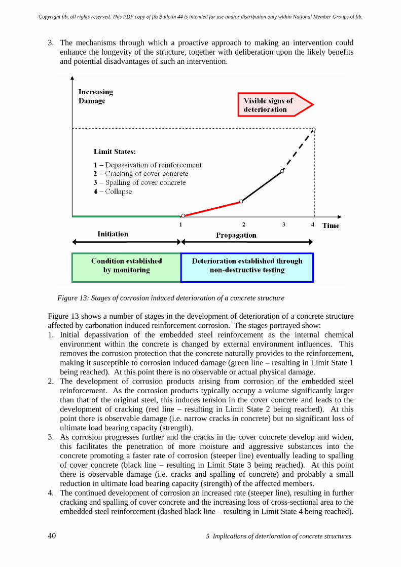
40 5 Implications of deterioration of concrete structures
3. The mechanisms through which a proactive approach to making an intervention could enhance the longevity of the structure, together with deliberation upon the likely benefits and potential disadvantages of such an intervention.
Figure 13: Stages of corrosion induced deterioration of a concrete structure Figure 13 shows a number of stages in the development of deterioration of a concrete structure affected by carbonation induced reinforcement corrosion. The stages portrayed show: 1. Initial depassivation of the embedded steel reinforcement as the internal chemical
environment within the concrete is changed by external environment influences. This removes the corrosion protection that the concrete naturally provides to the reinforcement, making it susceptible to corrosion induced damage (green line – resulting in Limit State 1 being reached). At this point there is no observable or actual physical damage.
2. The development of corrosion products arising from corrosion of the embedded steel reinforcement. As the corrosion products typically occupy a volume significantly larger than that of the original steel, this induces tension in the cover concrete and leads to the development of cracking (red line – resulting in Limit State 2 being reached). At this point there is observable damage (i.e. narrow cracks in concrete) but no significant loss of ultimate load bearing capacity (strength).
3. As corrosion progresses further and the cracks in the cover concrete develop and widen, this facilitates the penetration of more moisture and aggressive substances into the concrete promoting a faster rate of corrosion (steeper line) eventually leading to spalling of cover concrete (black line – resulting in Limit State 3 being reached). At this point there is observable damage (i.e. cracks and spalling of concrete) and probably a small reduction in ultimate load bearing capacity (strength) of the affected members.
4. The continued development of corrosion an increased rate (steeper line), resulting in further cracking and spalling of cover concrete and the increasing loss of cross-sectional area to the embedded steel reinforcement (dashed black line – resulting in Limit State 4 being reached).
Copyright fib, all rights reserved. This PDF copy of fib Bulletin 44 is intended for use and/or distribution only within National Member Groups of fib.
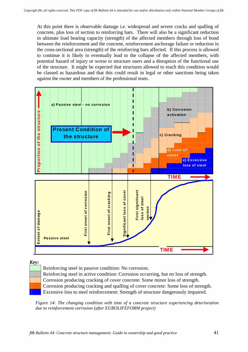
fib Bulletin 44: Concrete structure management: Guide to ownership and good practice 41
At this point there is observable damage i.e. widespread and severe cracks and spalling of concrete, plus loss of section to reinforcing bars. There will also be a significant reduction in ultimate load bearing capacity (strength) of the affected members through loss of bond between the reinforcement and the concrete, reinforcement anchorage failure or reduction in the cross-sectional area (strength) of the reinforcing bars affected. If this process is allowed to continue it is likely to eventually lead to the collapse of the affected members, with potential hazard of injury or worse to structure users and a disruption of the functional use of the structure. It might be expected that structures allowed to reach this condition would be classed as hazardous and that this could result in legal or other sanctions being taken against the owner and members of the professional team.
Key: Reinforcing steel in passive condition: No corrosion. Reinforcing steel in active condition: Corrosion occurring, but no loss of strength. Corrosion producing cracking of cover concrete: Some minor loss of strength. Corrosion producing cracking and spalling of cover concrete: Some loss of strength. Excessive loss to steel reinforcement: Strength of structure dangerously impaired.
Figure 14: The changing condition with time of a concrete structure experiencing deterioration due to reinforcement corrosion (after EUROLIFEFORM project)
a) Passive steel - no corro sionb) Corrosionactivation
c) Cracking
d) Loss o fcover
e) Excessive loss of s teel
TIME
Passive steel
TIME
Sign
ific
ant l
oss
of c
over
Firs
t sig
nific
ant
loss
of s
teel
se
ctio
n
Pro
po
rtio
n o
f th
e st
ruct
ure
Ext
ent o
f dam
age
Firs
t ons
et o
f cor
rosi
on
Firs
t on
set o
f cra
ckin
g
Present Condition of the structure
Copyright fib, all rights reserved. This PDF copy of fib Bulletin 44 is intended for use and/or distribution only within National Member Groups of fib.
42 5 Implications of deterioration of concrete structures
Figure 14 shows the changing condition of a deteriorating concrete structure with time and introduces the concept that at a particular time the degree of corrosion and associated damage varies across the structure. It can be seen that initially all the reinforcing steel in the structure is in a passive condition and that no corrosion is taking place. Over time an increasing proportion of the reinforcing steel / structure is affected by varying degrees of corrosion and associated cracking and spalling of the cover concrete. Thus as time goes by various parts of the structures become affected and the overall condition / structural strength of the member deteriorates.
5.2 Mechanisms of deterioration
The deterioration mechanisms causing durability problems in reinforced concrete structures are often grouped as follows. • Corrosion of reinforcement • Deterioration of the concrete itself • Physical damage to the structure Reinforcement corrosion typically results in cracking of the concrete, spalled concrete and potentially a decrease in load-bearing capacity due to factors such as a reduction in the cross sectional area of the reinforcement and disruption of the bond and anchorage of the reinforcing bars. The main causes of reinforcement corrosion are: • Carbonation of the concrete, which is caused by the permeation of atmospheric carbon
dioxide into the concrete over a period of years that changes the internal chemistry of the surface zone concrete. The effect is to removes the natural passivity protection afforded to the steel by the concrete, subsequently allowing corrosion to develop. The loss of protection usually takes place slowly over many years, but is dependent upon the quality of the placed concrete.
• The presence of significant levels of chloride ions in the concrete, either incorporated into the concrete when the structure was built or by subsequent ingress into the concrete from the external environment (e.g. through the use of de-icing salts or from the marine environment).
• Bacterial action can occur in some conditions, leading to conditions conductive to steel reinforcement corrosion (and attack on the concrete). For example, under anaerobic conditions found in sewage treatment hydrogen sulphide is produced which, as moisture is usually available, is converted by aerobic bacteria to form sulphuric acid. The acid can then attack exposed steel. These conditions also occasionally occur in sewers and other situations.
Damage due to deterioration of the concrete material itself may be caused by a number of mechanisms such as those listed below – also refer to Figure 8: • Freeze and thaw effects. • External chemical attack caused by acids, sulfates, nitrates etc. and including reactions
such as the thaumasite form of sulfate attack (TSA) and also biological / bacterial agents. • Internal deleterious chemical reactions such as leaching, alkali-aggregate reactions (AAR)
and alkali-silicate reactions (ASR), delayed etringite formation (DEF) etc. Physical damage to structures can arise from a variety of causes including: • Overloading • Fire • Impacts, accidents and malicious attack
Copyright fib, all rights reserved. This PDF copy of fib Bulletin 44 is intended for use and/or distribution only within National Member Groups of fib.
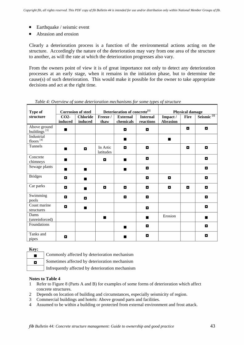
fib Bulletin 44: Concrete structure management: Guide to ownership and good practice 43
• Earthquake / seismic event • Abrasion and erosion Clearly a deterioration process is a function of the environmental actions acting on the structure. Accordingly the nature of the deterioration may vary from one area of the structure to another, as will the rate at which the deterioration progresses also vary. From the owners point of view it is of great importance not only to detect any deterioration processes at an early stage, when it remains in the initiation phase, but to determine the cause(s) of such deterioration. This would make it possible for the owner to take appropriate decisions and act at the right time.
Table 4: Overview of some deterioration mechanisms for some types of structure
Corrosion of steel
Deterioration of concrete[1]
Physical damage Type of structure
CO2-induced
Chloride induced
Freeze / thaw
External chemicals
Internal reactions
Impact / Abrasion
Fire Seismic [2]
Above ground buildings [3]
Industrial floors [4]
Tunnels In Artic
latitudes
Concrete chimneys
Sewage plants
Bridges
Car parks
Swimming pools
Coast marine structures
Dams (unreinforced)
Erosion
Foundations
Tanks and pipes
Key: Commonly affected by deterioration mechanism
Sometimes affected by deterioration mechanism Infrequently affected by deterioration mechanism Notes to Table 4 1 Refer to Figure 8 (Parts A and B) for examples of some forms of deterioration which affect
concrete structures. 2 Depends on location of building and circumstances, especially seismicity of region. 3 Commercial buildings and hotels: Above ground parts and facilities. 4 Assumed to be within a building or protected from external environment and frost attack.
Copyright fib, all rights reserved. This PDF copy of fib Bulletin 44 is intended for use and/or distribution only within National Member Groups of fib.
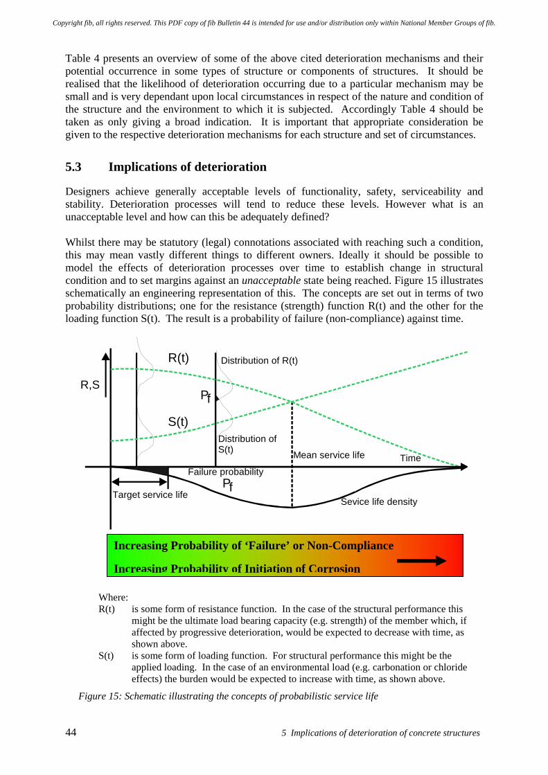
44 5 Implications of deterioration of concrete structures
Table 4 presents an overview of some of the above cited deterioration mechanisms and their potential occurrence in some types of structure or components of structures. It should be realised that the likelihood of deterioration occurring due to a particular mechanism may be small and is very dependant upon local circumstances in respect of the nature and condition of the structure and the environment to which it is subjected. Accordingly Table 4 should be taken as only giving a broad indication. It is important that appropriate consideration be given to the respective deterioration mechanisms for each structure and set of circumstances.
5.3 Implications of deterioration
Designers achieve generally acceptable levels of functionality, safety, serviceability and stability. Deterioration processes will tend to reduce these levels. However what is an unacceptable level and how can this be adequately defined? Whilst there may be statutory (legal) connotations associated with reaching such a condition, this may mean vastly different things to different owners. Ideally it should be possible to model the effects of deterioration processes over time to establish change in structural condition and to set margins against an unacceptable state being reached. Figure 15 illustrates schematically an engineering representation of this. The concepts are set out in terms of two probability distributions; one for the resistance (strength) function R(t) and the other for the loading function S(t). The result is a probability of failure (non-compliance) against time.
Mean service life
Sevice life density
Time Failure probability
Target service life
Distribution of S(t)
S(t)
R(t)
R,S P f
Pf
Distribution of R(t)
Where: R(t) is some form of resistance function. In the case of the structural performance this
might be the ultimate load bearing capacity (e.g. strength) of the member which, if affected by progressive deterioration, would be expected to decrease with time, as shown above.
S(t) is some form of loading function. For structural performance this might be the applied loading. In the case of an environmental load (e.g. carbonation or chloride effects) the burden would be expected to increase with time, as shown above.
Figure 15: Schematic illustrating the concepts of probabilistic service life
Increasing Probability of ‘Failure’ or Non-Compliance Increasing Probability of Initiation of Corrosion
Copyright fib, all rights reserved. This PDF copy of fib Bulletin 44 is intended for use and/or distribution only within National Member Groups of fib.
fib Bulletin 44: Concrete structure management: Guide to ownership and good practice 45
When considering the potential deterioration mechanisms it is important to maintain a sense of proportion and to recognise that overall the fraction of new construction and existing structures requiring repair is relatively small. Further, the amount of repair required for reasons of safety and structural integrity accounts for only a fraction of all interventions carried out. For example, there are very few incidents of structural collapse in Europe due to the deterioration of reinforced concrete structures. It might be argued that some European countries do more repair work than is perhaps strictly necessary for reasons of structural safety. Generally damage to a concrete structure is the result of a deterioration process acting over a period of time, probably over years and possibly over decades. Only some causes of physical damage, such as earthquake, impact or overloading may result in the sudden appearance of severe damage. Once damage has been created, further deterioration and damage may progress at a relatively fast rate as illustrated above in Figure 13. The first signs of change or deterioration are often neglected. When concrete suffers from abrasion or erosion, damage appears as the loss of the fine material on the surface of the concrete, resulting in a rougher surface. In some situations this may cause problems in respect of the use of the structure (e.g.: perhaps the creation of dust in clean environments). Darker areas may be a sign of water penetration into the concrete. When such water contains chlorides, this may increase the risk of reinforcement corrosion. Most of the deteriorating processes (e.g. AAR, ettringite formation and corrosion) result in the cracking of concrete. Small cracks may thus be an early indication of future damage. An intervention at this stage (e.g. small repairs, application of a coating, etc …) will generally provide reasonable results for modest concrete repair and protection efforts. Once the first visible signs of deterioration (cracks) have appeared, the aging process will progress with an increasing speed as described before, as water and contaminants may penetrate more easily into the concrete. Small cracks will tend to become bigger with time. Spalling may subsequently occur, which may create a danger of pieces of concrete falling and thereby creating a hazard for users and passers-by. Repairing the damage at this stage generally involves several steps, such as cleaning the corrosion products and contaminants from the reinforcing bars, making a patch repair, etc. These processes are described in more detail later in the report. When corrosion of the reinforcement is severe, perhaps only occurring locally to some of the bars, or when significant deformations or structural cracks are noticed, consideration must be given to the remaining structural capacity of the members affected and potentially of the overall structure. As a precaution access to the affected part of the structure would normally be restricted, whilst the assessment and necessary works are carried out. If the situation has clearly become dangerous access to the structure, and possibly to the zone surrounding it, would generally be completely forbidden. In addition to the repair of the damage, replacement of reinforcement or strengthening may be necessary. In some cases, demolition or replacement of parts of the structure or the whole structure may be the only reasonable course of action. The management of concrete structures could be improved by: • Early intervention, before damage is visible. • Proactive monitoring and maintenance in support of this. • Correct diagnosis of the problem and mechanism(s) causing the deterioration. • Effective intervention systems for preventive and remedial treatments.
Copyright fib, all rights reserved. This PDF copy of fib Bulletin 44 is intended for use and/or distribution only within National Member Groups of fib.

Copyright fib, all rights reserved. This PDF copy of fib Bulletin 44 is intended for use and/or distribution only within National Member Groups of fib.
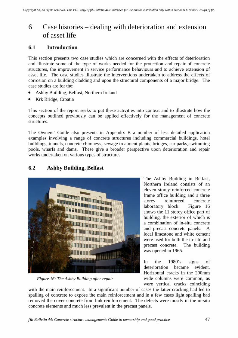
fib Bulletin 44: Concrete structure management: Guide to ownership and good practice 47
6 Case histories – dealing with deterioration and extension of asset life
6.1 Introduction
This section presents two case studies which are concerned with the effects of deterioration and illustrate some of the type of works needed for the protection and repair of concrete structures, the improvement in service performance behaviours and to achieve extension of asset life. The case studies illustrate the interventions undertaken to address the effects of corrosion on a building cladding and upon the structural components of a major bridge. The case studies are for the: • Ashby Building, Belfast, Northern Ireland • Krk Bridge, Croatia This section of the report seeks to put these activities into context and to illustrate how the concepts outlined previously can be applied effectively for the management of concrete structures. The Owners’ Guide also presents in Appendix B a number of less detailed application examples involving a range of concrete structures including commercial buildings, hotel buildings, tunnels, concrete chimneys, sewage treatment plants, bridges, car parks, swimming pools, wharfs and dams. These give a broader perspective upon deterioration and repair works undertaken on various types of structures.
6.2 Ashby Building, Belfast
The Ashby Building in Belfast, Northern Ireland consists of an eleven storey reinforced concrete frame office building and a three storey reinforced concrete laboratory block. Figure 16 shows the 11 storey office part of building, the exterior of which is a combination of in-situ concrete and precast concrete panels. A local limestone and white cement were used for both the in-situ and precast concrete. The building was opened in 1965. In the 1980’s signs of deterioration became evident. Horizontal cracks in the 200mm wide columns were common, as were vertical cracks coinciding
with the main reinforcement. In a significant number of cases the latter cracking had led to spalling of concrete to expose the main reinforcement and in a few cases light spalling had removed the cover concrete from link reinforcement. The defects were mostly in the in-situ concrete elements and much less prevalent in the precast panels.
Figure 16: The Ashby Building after repair
Copyright fib, all rights reserved. This PDF copy of fib Bulletin 44 is intended for use and/or distribution only within National Member Groups of fib.
48 6 Case histories – dealing with deterioration and extension of asset life
In 1989 a programme of inspection and testing was carried out and engineers concluded that: • The strength of the concrete was generally satisfactory. • The permeability was variable and higher than normally observed for good concrete. • Half-cell measurements indicated that corrosion was probable in many areas, often
coinciding with the areas of higher permeability. • Cover to the reinforcement was low, in some cases less than 10mm. • Micro-cracking was present near the surface of the panels. • The samples of concrete tested had poor freeze-thaw resistance. In summary therefore the problem was identified as one of concrete with relatively high permeability combined with low freeze-thaw resistance and low cover to the reinforcement. The repair procedure adopted was reasonably standard and involved removing cracked and loose concrete by water jetting, replacing this concrete with a repair mortar and finally applying a surface treatment which acted both as a cosmetic finish and also as a barrier to future water ingress. The materials selected were a polymer modified mortar and an acrylic coating applied in three coats. In 1991 a pilot contract was let to trial materials and methods and to investigate issues such as the impact of the works on the building users. Following this the main contract was let in 1992 with work restricted to summer months when weather conditions would be more suitable for the materials and disruption to the users less. The contract sum was £255,776. This included some work to window frames and redecorating inside, both of which were necessary as a result of water ingress around the window frames and through the concrete columns. The breakdown of the work is illustrated in Table 5 below.
Table 5: Repair costs for the Ashby Building, Belfast Activity
Spend (£) Percentage Spend
Insurance, accommodation, site administration £38,097 15%Access scaffolding £26,239 10%Concrete repair £116,140 45%Repair of windows and internal redecoration £57,908 23%External surface treatment £17,392 7%Total £255,776 100% Total less work to window frames and redecorating inside [Referred to as the 1992 Repair Cost]
£197,868 100%
For the purposes of comparing reactive and proactive approaches to asset management an estimate was made of the cost of the surface treatment alone (as an early preventive treatment). This came out as £47,000 for the first treatment; with the cost of a re-treatment being significantly lower, since less preparation and fewer coats would be required; at about £33,000 (at 1992 prices). The surface treatment used was estimated to need over-coating at 10 – 15 year intervals. This seemed reasonable as twelve years had elapsed since the treatment had been applied and it was still sound, with no evidence of any cracking in the concrete. More significantly there is no evidence of moisture penetration into the interior of the building.
Copyright fib, all rights reserved. This PDF copy of fib Bulletin 44 is intended for use and/or distribution only within National Member Groups of fib.
fib Bulletin 44: Concrete structure management: Guide to ownership and good practice 49
Thus the implication of this case study is that a regular maintenance programme would have saved money over the first 40 years of the life of the building (1965 – 2005). Applying a coating to the concrete in a1970 and then at 15 year intervals would have cost in the region of £80,000 (at 1992 prices). This is based on £47,000 for the first treatment (1970) and £33,000 for each re-treatment (1985 and 2000). Table 6 details the notional costs of the preventive works approach and expresses these as a percentage of the 1992 Repair Cost (£197,868). It will be seen that it is estimated that these two preventive treatments would have amounted to some 57% of the 1992 Repair Cost. These results are presented graphically in Figure 17.
Table 6: Notional preventive treatment costs for the Ashby Building, Belfast Activity
Date Cost Cumulative Cost
% of 1992 Repair Cost [1]
Ashby Building opened 1965 Action assumed to be taken First preventive treatment 1970 £47,000 £47,000 24% Second preventive treatment 1985 £33,000 £80,000 40% Third preventive treatment 2000 £33,000 £113,000 57% Fourth preventive treatment 2015 £33,000 £146,000 74% Fifth preventive treatment 2030 £33,000 £179,000 90% [1] The 1992 Repair Cost is taken to be the total cost of the works undertaken less work to window frames and redecorating inside (refer Table 5).
Repair Cost Timeline for Ashby Building
0%
20%
40%
60%
80%
100%
120%
1960 1970 1980 1990 2000 2010 2020 2030 2040
Date
% 1
992
Rep
air
Cos
t
PreventiveWorks: %Repair Cost
Repair Works
1965 Building opened
1992 building repair
Saving by adopting preventive works
1st treatment
2nd treatment
3rd treatment
4th treatment
Figure 17: Cost timeline for the Ashby Building, Belfast – Comparison of 1992 repair versus preventive works approach
Copyright fib, all rights reserved. This PDF copy of fib Bulletin 44 is intended for use and/or distribution only within National Member Groups of fib.
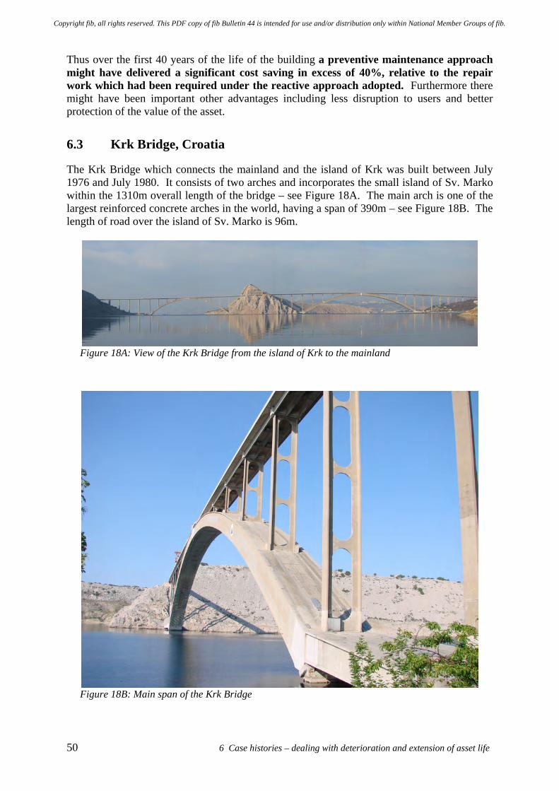
50 6 Case histories – dealing with deterioration and extension of asset life
Thus over the first 40 years of the life of the building a preventive maintenance approach might have delivered a significant cost saving in excess of 40%, relative to the repair work which had been required under the reactive approach adopted. Furthermore there might have been important other advantages including less disruption to users and better protection of the value of the asset.
6.3 Krk Bridge, Croatia
The Krk Bridge which connects the mainland and the island of Krk was built between July 1976 and July 1980. It consists of two arches and incorporates the small island of Sv. Marko within the 1310m overall length of the bridge – see Figure 18A. The main arch is one of the largest reinforced concrete arches in the world, having a span of 390m – see Figure 18B. The length of road over the island of Sv. Marko is 96m.
Figure 18A: View of the Krk Bridge from the island of Krk to the mainland
Figure 18B: Main span of the Krk Bridge
Copyright fib, all rights reserved. This PDF copy of fib Bulletin 44 is intended for use and/or distribution only within National Member Groups of fib.
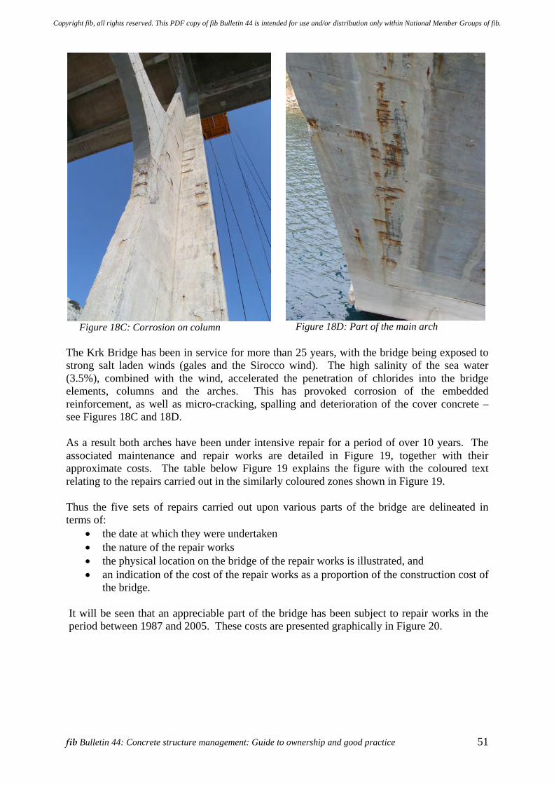
fib Bulletin 44: Concrete structure management: Guide to ownership and good practice 51
Figure 18C: Corrosion on column
Figure 18D: Part of the main arch
The Krk Bridge has been in service for more than 25 years, with the bridge being exposed to strong salt laden winds (gales and the Sirocco wind). The high salinity of the sea water (3.5%), combined with the wind, accelerated the penetration of chlorides into the bridge elements, columns and the arches. This has provoked corrosion of the embedded reinforcement, as well as micro-cracking, spalling and deterioration of the cover concrete – see Figures 18C and 18D. As a result both arches have been under intensive repair for a period of over 10 years. The associated maintenance and repair works are detailed in Figure 19, together with their approximate costs. The table below Figure 19 explains the figure with the coloured text relating to the repairs carried out in the similarly coloured zones shown in Figure 19. Thus the five sets of repairs carried out upon various parts of the bridge are delineated in terms of:
• the date at which they were undertaken • the nature of the repair works • the physical location on the bridge of the repair works is illustrated, and • an indication of the cost of the repair works as a proportion of the construction cost of
the bridge. It will be seen that an appreciable part of the bridge has been subject to repair works in the period between 1987 and 2005. These costs are presented graphically in Figure 20.
Copyright fib, all rights reserved. This PDF copy of fib Bulletin 44 is intended for use and/or distribution only within National Member Groups of fib.
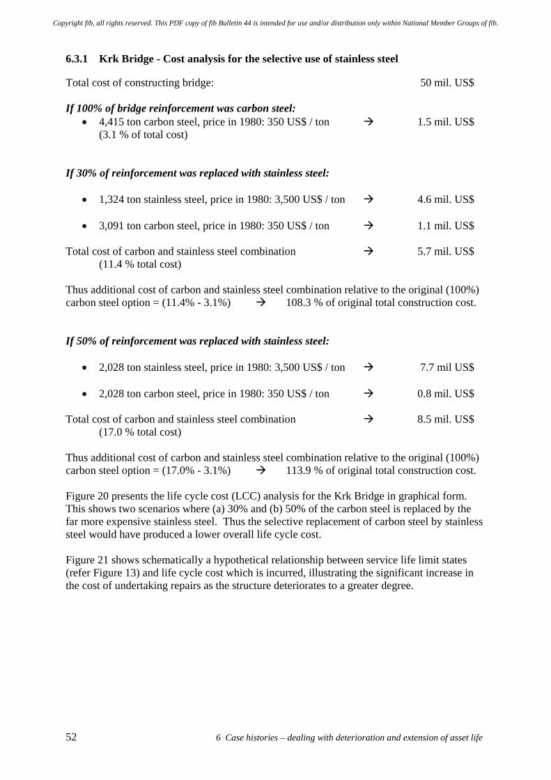
52 6 Case histories – dealing with deterioration and extension of asset life
6.3.1 Krk Bridge - Cost analysis for the selective use of stainless steel
Total cost of constructing bridge: 50 mil. US$ If 100% of bridge reinforcement was carbon steel:
• 4,415 ton carbon steel, price in 1980: 350 US$ / ton 1.5 mil. US$ (3.1 % of total cost) If 30% of reinforcement was replaced with stainless steel:
• 1,324 ton stainless steel, price in 1980: 3,500 US$ / ton 4.6 mil. US$
• 3,091 ton carbon steel, price in 1980: 350 US$ / ton 1.1 mil. US$ Total cost of carbon and stainless steel combination 5.7 mil. US$ (11.4 % total cost) Thus additional cost of carbon and stainless steel combination relative to the original (100%) carbon steel option = (11.4% - 3.1%) 108.3 % of original total construction cost. If 50% of reinforcement was replaced with stainless steel:
• 2,028 ton stainless steel, price in 1980: 3,500 US$ / ton 7.7 mil US$
• 2,028 ton carbon steel, price in 1980: 350 US$ / ton 0.8 mil. US$ Total cost of carbon and stainless steel combination 8.5 mil. US$ (17.0 % total cost) Thus additional cost of carbon and stainless steel combination relative to the original (100%) carbon steel option = (17.0% - 3.1%) 113.9 % of original total construction cost. Figure 20 presents the life cycle cost (LCC) analysis for the Krk Bridge in graphical form. This shows two scenarios where (a) 30% and (b) 50% of the carbon steel is replaced by the far more expensive stainless steel. Thus the selective replacement of carbon steel by stainless steel would have produced a lower overall life cycle cost. Figure 21 shows schematically a hypothetical relationship between service life limit states (refer Figure 13) and life cycle cost which is incurred, illustrating the significant increase in the cost of undertaking repairs as the structure deteriorates to a greater degree.
Copyright fib, all rights reserved. This PDF copy of fib Bulletin 44 is intended for use and/or distribution only within National Member Groups of fib.
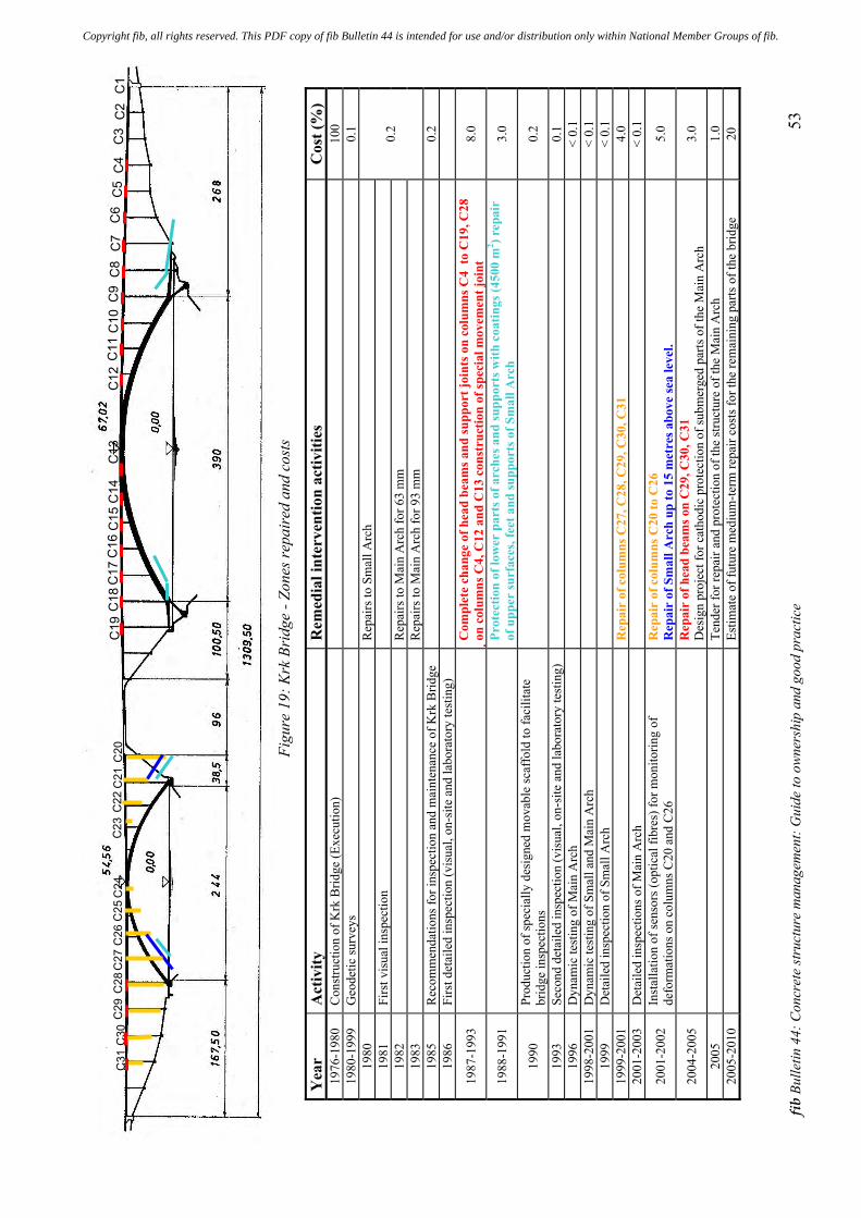
fib B
ulle
tin 4
4: C
oncr
ete
stru
ctur
e m
anag
emen
t: G
uide
to o
wner
ship
and
goo
d pr
actic
e 53
Fi
gure
19:
Krk
Bri
dge
- >on
es re
pair
ed a
nd c
osts
!ea
r A
ctiv
ity
Rem
edia
l int
erve
ntio
n ac
tiviti
es
Cos
t (%
) 19
76-1
980
Con
stru
ctio
n of
Krk
Brid
ge (E
xecu
tion)
100
1980
-199
9 G
eode
tic su
rvey
s
0.1
1980
Rep
airs
to S
mal
l Arc
h
1981
Fi
rst v
isua
l ins
pect
ion
19
82
R
epai
rs to
Mai
n A
rch
for 6
3 m
m
1983
Rep
airs
to M
ain
Arc
h fo
r 93
mm
0.2
1985
R
ecom
men
datio
ns fo
r ins
pect
ion
and
mai
nten
ance
of K
rk B
ridge
0.2
1986
Fi
rst d
etai
led
insp
ectio
n (v
isua
l, on
-site
and
labo
rato
ry te
stin
g)
1987
-199
3
Com
plet
e ch
ange
of h
ead
beam
s and
supp
ort =
oint
s on
colu
mns
C4
to C
19, C
28
!on c
olum
ns C
4, C
12 a
nd C
13 c
onst
ruct
ion
of sp
ecia
l mov
emen
t =oi
nt
8.0
1988
-199
1
Prot
ectio
n of
low
er p
arts
of a
rche
s and
supp
orts
with
coa
tings
(450
0 m
2 ) rep
air
of u
pper
surf
aces
, fee
t and
supp
orts
of S
mal
l Arc
h 3.
0
1990
Pr
oduc
tion
of sp
ecia
lly d
esig
ned
mov
able
scaf
fold
to fa
cilit
ate
brid
ge in
spec
tions
0.2
1993
Se
cond
det
aile
d in
spec
tion
(vis
ual,
on-s
ite a
nd la
bora
tory
test
ing)
0.1
1996
D
ynam
ic te
stin
g of
Mai
n A
rch
<
0.1
1998
-200
1 D
ynam
ic te
stin
g of
Sm
all a
nd M
ain
Arc
h
< 0.
1 19
99
Det
aile
d in
spec
tion
of S
mal
l Arc
h
< 0.
1 19
99-2
001
R
epai
r of
col
umns
C27
, C28
, C29
, C30
, C31
4.
0 20
01-2
003
Det
aile
d in
spec
tions
of M
ain
Arc
h
< 0.
1
2001
-200
2 In
stal
latio
n of
sens
ors (
optic
al fi
bres
) for
mon
itorin
g of
de
form
atio
ns o
n co
lum
ns C
20 a
nd C
26
Rep
air
of c
olum
ns C
20 to
C26
R
epai
r of
Sm
all A
rch
up to
15
met
res a
bove
sea
leve
l. 5.
0
2004
-200
5
Rep
air
of h
ead
beam
s on
C29
, C30
, C31
D
esig
n pr
ojec
t for
cat
hodi
c pr
otec
tion
of su
bmer
ged
parts
of t
he M
ain
Arc
h 3.
0
2005
Tend
er fo
r rep
air a
nd p
rote
ctio
n of
the
stru
ctur
e of
the
Mai
n A
rch
1.0
2005
-201
0
Estim
ate
of fu
ture
med
ium
-term
repa
ir co
sts f
or th
e re
mai
ning
par
ts o
f the
brid
ge
20
!"#
!$#
!%#
!&#
!'#
!(#
!)#
!*#
!+#
!",#
!""#
!"$#
!"%#
!"&#
!"'#
!"(#
!")#
!"*#
!"+#
!$'#
!$"# !$,#
!$$#
!$%#
!$&#
!$(#
!$)#
!$*#
!$+#
!%,
!%"#
Copyright fib, all rights reserved. This PDF copy of fib Bulletin 44 is intended for use and/or distribution only within National Member Groups of fib.
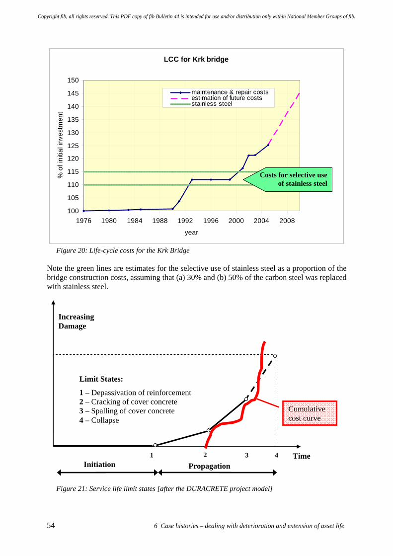
54 6 Case histories – dealing with deterioration and extension of asset life
LCC for Krk bridge
100
105
110
115
120
125
130
135
140
145
150
1976 1980 1984 1988 1992 1996 2000 2004 2008
year
% o
f ini
tial i
nves
tmen
t
maintenance & repair costsestimation of future costsstainless steel
Figure 20: Life-cycle costs for the Krk Bridge
Note the green lines are estimates for the selective use of stainless steel as a proportion of the bridge construction costs, assuming that (a) 30% and (b) 50% of the carbon steel was replaced with stainless steel.
Figure 21: Service life limit states [after the DURACRETE project model]
Time 1 2 3 4
Increasing Damage
Limit States:
1 – Depassivation of reinforcement 2 – Cracking of cover concrete 3 – Spalling of cover concrete 4 – Collapse
Initiation Propagation
Cumulative cost curve
Costs for selective use of stainless steel
Copyright fib, all rights reserved. This PDF copy of fib Bulletin 44 is intended for use and/or distribution only within National Member Groups of fib.
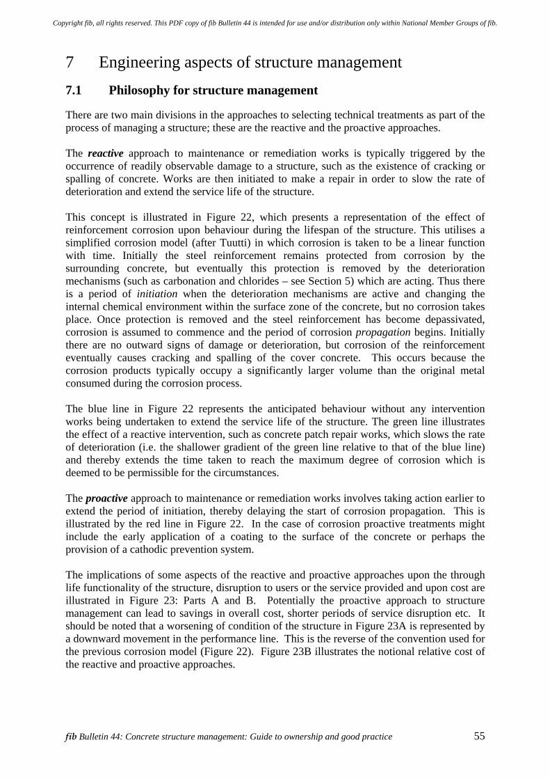
fib Bulletin 44: Concrete structure management: Guide to ownership and good practice 55
7 Engineering aspects of structure management 7.1 Philosophy for structure management
There are two main divisions in the approaches to selecting technical treatments as part of the process of managing a structure; these are the reactive and the proactive approaches. The reactive approach to maintenance or remediation works is typically triggered by the occurrence of readily observable damage to a structure, such as the existence of cracking or spalling of concrete. Works are then initiated to make a repair in order to slow the rate of deterioration and extend the service life of the structure. This concept is illustrated in Figure 22, which presents a representation of the effect of reinforcement corrosion upon behaviour during the lifespan of the structure. This utilises a simplified corrosion model (after Tuutti) in which corrosion is taken to be a linear function with time. Initially the steel reinforcement remains protected from corrosion by the surrounding concrete, but eventually this protection is removed by the deterioration mechanisms (such as carbonation and chlorides – see Section 5) which are acting. Thus there is a period of initiation when the deterioration mechanisms are active and changing the internal chemical environment within the surface zone of the concrete, but no corrosion takes place. Once protection is removed and the steel reinforcement has become depassivated, corrosion is assumed to commence and the period of corrosion propagation begins. Initially there are no outward signs of damage or deterioration, but corrosion of the reinforcement eventually causes cracking and spalling of the cover concrete. This occurs because the corrosion products typically occupy a significantly larger volume than the original metal consumed during the corrosion process. The blue line in Figure 22 represents the anticipated behaviour without any intervention works being undertaken to extend the service life of the structure. The green line illustrates the effect of a reactive intervention, such as concrete patch repair works, which slows the rate of deterioration (i.e. the shallower gradient of the green line relative to that of the blue line) and thereby extends the time taken to reach the maximum degree of corrosion which is deemed to be permissible for the circumstances. The proactive approach to maintenance or remediation works involves taking action earlier to extend the period of initiation, thereby delaying the start of corrosion propagation. This is illustrated by the red line in Figure 22. In the case of corrosion proactive treatments might include the early application of a coating to the surface of the concrete or perhaps the provision of a cathodic prevention system. The implications of some aspects of the reactive and proactive approaches upon the through life functionality of the structure, disruption to users or the service provided and upon cost are illustrated in Figure 23: Parts A and B. Potentially the proactive approach to structure management can lead to savings in overall cost, shorter periods of service disruption etc. It should be noted that a worsening of condition of the structure in Figure 23A is represented by a downward movement in the performance line. This is the reverse of the convention used for the previous corrosion model (Figure 22). Figure 23B illustrates the notional relative cost of the reactive and proactive approaches.
Copyright fib, all rights reserved. This PDF copy of fib Bulletin 44 is intended for use and/or distribution only within National Member Groups of fib.
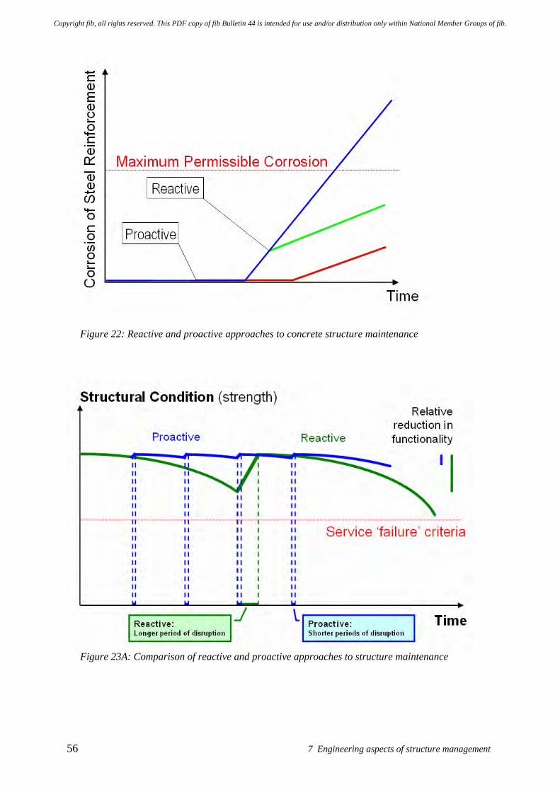
56 7 Engineering aspects of structure management
Figure 22: Reactive and proactive approaches to concrete structure maintenance
Figure 23A: Comparison of reactive and proactive approaches to structure maintenance
Copyright fib, all rights reserved. This PDF copy of fib Bulletin 44 is intended for use and/or distribution only within National Member Groups of fib.
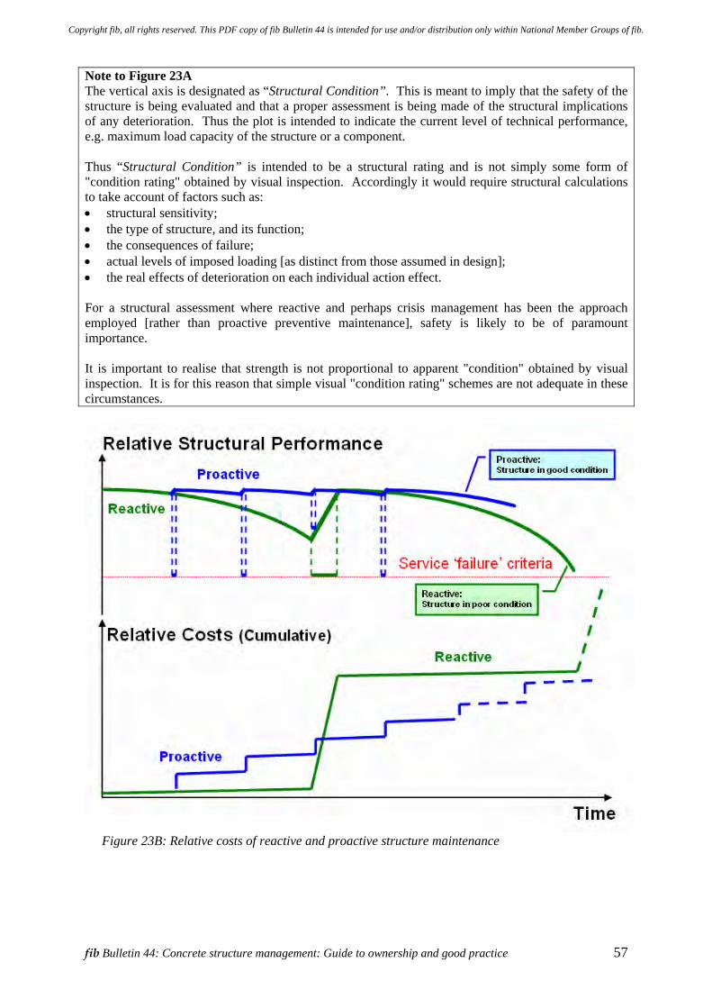
fib Bulletin 44: Concrete structure management: Guide to ownership and good practice 57
Note to Figure 23A The vertical axis is designated as “Structural Condition”. This is meant to imply that the safety of the structure is being evaluated and that a proper assessment is being made of the structural implications of any deterioration. Thus the plot is intended to indicate the current level of technical performance, e.g. maximum load capacity of the structure or a component. Thus “Structural Condition” is intended to be a structural rating and is not simply some form of "condition rating" obtained by visual inspection. Accordingly it would require structural calculations to take account of factors such as: • structural sensitivity; • the type of structure, and its function; • the consequences of failure; • actual levels of imposed loading [as distinct from those assumed in design]; • the real effects of deterioration on each individual action effect. For a structural assessment where reactive and perhaps crisis management has been the approach employed [rather than proactive preventive maintenance], safety is likely to be of paramount importance. It is important to realise that strength is not proportional to apparent "condition" obtained by visual inspection. It is for this reason that simple visual "condition rating" schemes are not adequate in these circumstances.
Figure 23B: Relative costs of reactive and proactive structure maintenance
Copyright fib, all rights reserved. This PDF copy of fib Bulletin 44 is intended for use and/or distribution only within National Member Groups of fib.
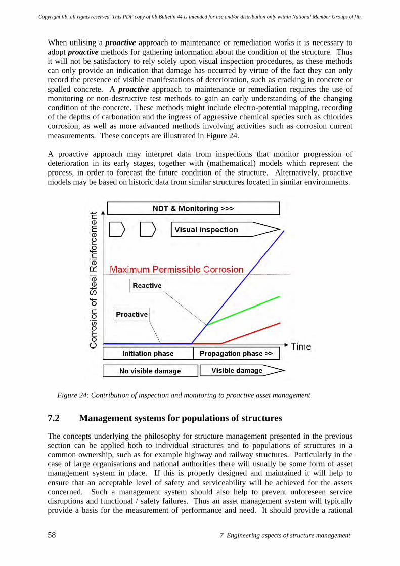
58 7 Engineering aspects of structure management
When utilising a proactive approach to maintenance or remediation works it is necessary to adopt proactive methods for gathering information about the condition of the structure. Thus it will not be satisfactory to rely solely upon visual inspection procedures, as these methods can only provide an indication that damage has occurred by virtue of the fact they can only record the presence of visible manifestations of deterioration, such as cracking in concrete or spalled concrete. A proactive approach to maintenance or remediation requires the use of monitoring or non-destructive test methods to gain an early understanding of the changing condition of the concrete. These methods might include electro-potential mapping, recording of the depths of carbonation and the ingress of aggressive chemical species such as chlorides corrosion, as well as more advanced methods involving activities such as corrosion current measurements. These concepts are illustrated in Figure 24. A proactive approach may interpret data from inspections that monitor progression of deterioration in its early stages, together with (mathematical) models which represent the process, in order to forecast the future condition of the structure. Alternatively, proactive models may be based on historic data from similar structures located in similar environments.
Figure 24: Contribution of inspection and monitoring to proactive asset management
7.2 Management systems for populations of structures
The concepts underlying the philosophy for structure management presented in the previous section can be applied both to individual structures and to populations of structures in a common ownership, such as for example highway and railway structures. Particularly in the case of large organisations and national authorities there will usually be some form of asset management system in place. If this is properly designed and maintained it will help to ensure that an acceptable level of safety and serviceability will be achieved for the assets concerned. Such a management system should also help to prevent unforeseen service disruptions and functional / safety failures. Thus an asset management system will typically provide a basis for the measurement of performance and need. It should provide a rational
Copyright fib, all rights reserved. This PDF copy of fib Bulletin 44 is intended for use and/or distribution only within National Member Groups of fib.
fib Bulletin 44: Concrete structure management: Guide to ownership and good practice 59
way of gathering and collating data, providing processes to assess this and of using the resulting information to rationalise and facilitate decision making. These processes may utilise some form of life cycle cost (LCC) analysis to promote the efficient and effective use of the available financial resources between competing demands associated with different structures. Thus an asset management system will include sets of procedures for organising and undertaking various operational activities such as inspection, assessment of structural and non-structural components, maintenance, as well as repair and protection interventions. It might encompass a wide range of parameters such as structural safety, user satisfaction, asset value, legally-defined performance requirements, government defined policy related objectives, as well as matters such as sustainability and social issues (see Section 4.2). The complexity of asset management system will depend upon matters such as the type, nature, number, condition and usage of the assets concerned. Inevitably this requires integrated consideration of engineering, functional and financial factors. Commonly these systems will need to address issues of budgets, phasing of works, potential linkages between proposed works and the operation of the wider network; as would be necessary for major works upon critical highway, railway or similar structures. As asset management systems have been developed in response to the needs of particular owners or groups of assets, they vary considerably in their nature and methods of operation. Some very sophisticated asset management systems exist and are routinely used, particularly for highway and related structures. There is a wealth of information available in the literature on asset management systems, with numerous documents and standards available for the management of highway and related structures.
7.3 Planning and implementing through-life care of a structure
7.3.1 Introduction
Critical aspects of planning and implementing through-life care of a structure are the service life period for which the structure is designed and the associated maintenance plan put in place to support this. The design service life (refer Boxes 1 and 2 and Figure 15) is the assumed period for which a structure, or part of it, is to be used for its intended purpose, with anticipated maintenance but without major repair being necessary. Design service life is defined by the selection of appropriate values for the following parameters: • performance limit state, • service life period (number of years), and • level of reliability of not passing the limit state during this period. The durability of the structure in its environment needs to be such that it remains fit for use throughout its design service life. This requirement can be achieved in various ways: • By designing suitable protective or mitigating systems. • By using materials that, with appropriate maintenance, will not degenerate during the
design service life. • By over-dimensioning the components of the structure that will experience deterioration
to compensate for the prospective deterioration during the design service life (i.e. by sacrificial provision / over-sizing of components).
Copyright fib, all rights reserved. This PDF copy of fib Bulletin 44 is intended for use and/or distribution only within National Member Groups of fib.
60 7 Engineering aspects of structure management
• By choosing a shorter lifetime for the structural elements and making provision for them to be replaced one or more times during the design life.
The above needs to be undertaken in combination with appropriate inspection / investigation activities at fixed or condition dependant intervals and with appropriate maintenance activities.
7.3.2 Design and assessment considerations
Structural and service life design needs to achieve appropriate levels of safety, in addition to seeking to ensure that the structure is durable for the chosen design service life. These issues are addressed by establishing the required level of reliability for the structural design and the associated requirements for design supervision and execution control. Considerations may also need to include the potential implications of corrosion of reinforcing bars or other form of deterioration upon the strength of a structure. In the context of these assessments it is important that the actual action (loading) and resistance values be considered.
7.3.2.1 Consequence and reliability classes For the purpose of establishing an appropriate level of safety for a particular structure or structural component, consideration should be given during its design to its use and to the potential consequences of its structural failure (i.e. collapse). This process utilises the concept of consequence classes (CC), with the criterion for classification being as set down below. The consequence classes; associated scale of impact in terms of loss of human life / economic, social or environmental consequences; and examples of how various building and civil engineering works might be classified follow: Class and Impact Examples • CC3 High: Grandstands, public buildings where consequences of failure
are high (e.g. a concert hall). • CC2 Considerable: Residential and office buildings, public buildings where
consequences of failure are significant (e.g. an office building). • CC1 Low: Agricultural buildings where people do not normally enter (e.g.
storage buildings), greenhouses. Not all components in a structure need be designed to the same consequence class and, depending on the structural form and decisions made during design, particular components may be designed to the requirements of different consequence classes. Thus if a particular component is critical to the safety of the overall building, referred to in engineering parlance as the ultimate limit state, it would be deemed to be more important than other components because the consequences of its structural failure would be far greater (i.e. a larger proportion of the building might collapse as a result of its failure, potentially with a greater number of fatalities and injuries). Accordingly the component would be designed to the requirements of a higher consequence class, which require a higher reliability level to be achieved (i.e. a safer structure / more certain outcome / lower probability of an adverse outcome). Thus the reliability level is a measure of the certainty with which a structure or a structural component is able to fulfil the specified performance requirements, such as its load-carrying capacity. Reliability is usually expressed in probabilistic terms. It is commonly quoted in terms of a non-dimensional parameter, the reliability index.
Copyright fib, all rights reserved. This PDF copy of fib Bulletin 44 is intended for use and/or distribution only within National Member Groups of fib.
fib Bulletin 44: Concrete structure management: Guide to ownership and good practice 61
The above concepts can also be applied to the serviceability of a structure and also to its service life design. When serviceability performance requirements are not achieved, such as when the in-service deflection of a component exceeds a designated limit, these perhaps should be viewed as a non-compliance with the defined criteria, rather than just simply as a “failure”. The main implications of non-compliance tend to be a reduction in some form of functionality, which have mainly economic implications. Such non-compliances tend not to be safety related, as would be the case for a structural failure or collapse situation where injury and loss of human life may result. Thus the term “failure” tends to have emotive connotations that may not be appropriate to serviceability and service life design situations. In these circumstances it is reasonable for the cost of measures to achieve a particular performance reliability level to be taken into account. This will influence the choice of consequence class and thus the reliability index used in serviceability and service life design. For existing structures the costs of achieving a higher reliability level are usually high compared with those of a new structure being designed to meet serviceability and service life requirements. For this reason the target reliability for the serviceability of an existing structure will usually be set at a lower level. Similar considerations apply when a structural assessment is being undertaken to establish the safety of an existing building. The task of making this type of assessment is more difficult when the structure has experienced a degree of deterioration, especially when the extent and severity of the deterioration cannot be fully quantified.
7.3.2.2 Design supervision and execution control classes The level of design supervision and of execution control achieved have potential impacts upon the reliability of the overall performance achieved and reflects the various organisational quality control measures put into place. The requirements for these are outlined below. The design supervision (DS) classes; characteristics; and minimum recommended requirements for the checking of calculations, drawings and specifications might be classified as follows: Class and Characteristic Minimum recommended requirements • DS3 Extended supervision: Third party checking - undertaken by an organisation
different to that which performed the design. • DS2 Normal supervision: Second party checking - undertaken by different persons
within the organisation which performed the design. • DS1 Normal supervision: Self-checking - undertaken by the person who
performed the design. The execution control (EC) classes; characteristics; and minimum recommended requirements for inspection might be classified as follows: Class and Characteristic Minimum recommended requirements • EC3 Extended supervision: Third party inspection. • EC2 Normal supervision: Second party inspection - undertaken by the organisation
which performed the design. • EC1 Normal supervision: Self-inspection - undertaken by the person who
performed the design.
Copyright fib, all rights reserved. This PDF copy of fib Bulletin 44 is intended for use and/or distribution only within National Member Groups of fib.
62 7 Engineering aspects of structure management
The execution control classes may be linked to quality management classes implemented through appropriate quality management procedures. Inspection in this context is defined within ISO 9000 as “Conformity evaluation by observation and judgment accompanied as appropriate by measurement, testing or gauging”. The above execution control (EC) classes and minimum recommended requirements for inspection are compatible with those set down in the European and international standards which apply to the execution of concrete structures (EN 13670 and ISO / DIS 22966) with the objective of achieving the intended level of safety and serviceability required during the design service life. These inter-related issues are considered further in Appendix G, which is concerned with project specifications, including execution standards and quality plans.
7.3.2.3 Sensitivity of concrete components to deterioration As part of the above design process consideration may need to be given to the potential implications of deterioration, such as the corrosion of reinforcing bars, upon the strength of a structure. Sensitivity to this type of deterioration depends upon not only upon the severity of the corrosion (i.e. how much of the reinforcing bar cross-section has been lost due to corrosion) but, most importantly, where it has occurred on the structure and the function of the reinforcement damaged by the corrosion. For example, an engineering assessment is likely to seek to differentiate between corrosion affecting the following reinforcement functions and zones, with the most sensitive situation being given first. • Reinforcement in anchorage zones without confinement. • Shear reinforcement and anchorage zones with confinement. • Bending reinforcement out-side anchorage and lap zones.
7.3.3 Maintenance class
Requirements for maintenance of a structure, or its component parts, should be defined at the time of design. The structure should be allocated to a maintenance class. This is done on the basis of a number of factors; such as the social and economic importance of the structure, its function, the nature of its design and that of its components, design service life, potential threats and impact on third parties, the environmental conditions to which it is exposed, the possible mechanisms of deterioration, the ease of undertaking inspections and maintenance works, together with considerations of cost. One way of classifying these is as follows. Maintenance Class Comment A. Structures or parts thereof
requiring planned proactive maintenance works.
• Structures whose deterioration must not be apparent or where it would be technically unacceptable.
• Monumental, important or sensitive buildings and structures that are likely to be managed in this way.
B. Structures or parts thereof for which reactive repair is satisfactory.
• Structures for which remedial measures can be taken after deterioration becomes (visually) apparent.
• Buildings and other common structures.
Copyright fib, all rights reserved. This PDF copy of fib Bulletin 44 is intended for use and/or distribution only within National Member Groups of fib.
fib Bulletin 44: Concrete structure management: Guide to ownership and good practice 63
C. Structures or parts thereof for which maintenance works are not practical.
• Structures or parts thereof where it would be difficult economically and / or technically for direct inspection / testing and protection or remedial measures to be undertaken after construction, such as foundations.
As noted previously, an initial inspection and related testing should be conducted as required in order to collect the structure specific information needed for the preparation of a “Birth Certificate” for a particular structure. It is probable that assessment and judgments of performance of structures in Category C will need to be made based on indirect information gathering. For example, in the case of foundations this could involve activities such as structure or ground subsidence measurement. By definition, these processes will be reactive in nature. As such these procedures are only likely to provide an indication once problems reach an advanced state. For example, cracking, distortion and distress in a structure due to foundation movement will usually only be noticeable once appreciable foundation movement has occurred.
7.3.3.1 Inspection and investigation regimes (IIR) Potential inspection and investigation regimes might be classified as follows. Maintenance Class Inspection and Investigation Regimes (IIR) and
Comment A. Structures or parts thereof
requiring planned proactive maintenance works.
IIR3. A planned proactive approach undertaking systematic inspection, investigation and monitoring of parameters relevant to the deterioration process(es) that is (are) expected to be critical to achieving the service life required for the structure.
B. Structures or parts thereof
for which reactive repair is satisfactory.
IIR2. A reactive approach utilising an ad-hoc inspection and investigation regime.
IIR1. A planned or ad-hoc approach using a visual inspection regime.
C. Structures or parts thereof
for which maintenance works are not practical.
IIR0. Involves no direct physical inspection. However it maybe possible to gather indirect indications of performance through ancillary behaviours as noted above for structures in Maintenance Class C.
7.3.4 Types of through-life inspection and investigations
These can be classified on the basis of the nature of the inspection and the methods of investigation to be used. Important factors are the frequency and timing of inspections and investigation. These may be classified as detailed below.
Copyright fib, all rights reserved. This PDF copy of fib Bulletin 44 is intended for use and/or distribution only within National Member Groups of fib.
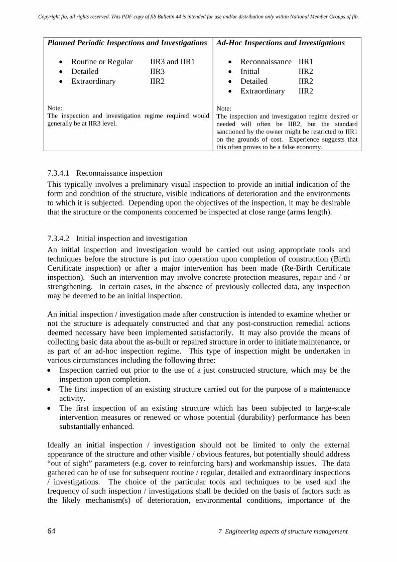
64 7 Engineering aspects of structure management
Planned Periodic Inspections and Investigations
• Routine or Regular IIR3 and IIR1 • Detailed IIR3 • Extraordinary IIR2
Note: The inspection and investigation regime required would generally be at IIR3 level.
Ad-Hoc Inspections and Investigations
• Reconnaissance IIR1 • Initial IIR2 • Detailed IIR2 • Extraordinary IIR2
Note: The inspection and investigation regime desired or needed will often be IIR2, but the standard sanctioned by the owner might be restricted to IIR1 on the grounds of cost. Experience suggests that this often proves to be a false economy.
7.3.4.1 Reconnaissance inspection This typically involves a preliminary visual inspection to provide an initial indication of the form and condition of the structure, visible indications of deterioration and the environments to which it is subjected. Depending upon the objectives of the inspection, it may be desirable that the structure or the components concerned be inspected at close range (arms length).
7.3.4.2 Initial inspection and investigation An initial inspection and investigation would be carried out using appropriate tools and techniques before the structure is put into operation upon completion of construction (Birth Certificate inspection) or after a major intervention has been made (Re-Birth Certificate inspection). Such an intervention may involve concrete protection measures, repair and / or strengthening. In certain cases, in the absence of previously collected data, any inspection may be deemed to be an initial inspection. An initial inspection / investigation made after construction is intended to examine whether or not the structure is adequately constructed and that any post-construction remedial actions deemed necessary have been implemented satisfactorily. It may also provide the means of collecting basic data about the as-built or repaired structure in order to initiate maintenance, or as part of an ad-hoc inspection regime. This type of inspection might be undertaken in various circumstances including the following three: • Inspection carried out prior to the use of a just constructed structure, which may be the
inspection upon completion. • The first inspection of an existing structure carried out for the purpose of a maintenance
activity. • The first inspection of an existing structure which has been subjected to large-scale
intervention measures or renewed or whose potential (durability) performance has been substantially enhanced.
Ideally an initial inspection / investigation should not be limited to only the external appearance of the structure and other visible / obvious features, but potentially should address “out of sight” parameters (e.g. cover to reinforcing bars) and workmanship issues. The data gathered can be of use for subsequent routine / regular, detailed and extraordinary inspections / investigations. The choice of the particular tools and techniques to be used and the frequency of such inspection / investigations shall be decided on the basis of factors such as the likely mechanism(s) of deterioration, environmental conditions, importance of the
Copyright fib, all rights reserved. This PDF copy of fib Bulletin 44 is intended for use and/or distribution only within National Member Groups of fib.
fib Bulletin 44: Concrete structure management: Guide to ownership and good practice 65
structure etc. It is usually necessary that the structure or the components concerned be inspected at close (touching) range (i.e. at arm length).
7.3.4.3 Routine or regular inspections and investigations Routine or regular inspections / investigations would be carried out periodically at intervals defined in the service life design, with the goal of identifying changing internal conditions within the concrete, indications of deterioration and the time of their first appearance. These inspections / investigations shall be carried out using appropriate tools and techniques to meet the objectives of the particular inspection. The choice of the particular tools and techniques to be used and the frequency of such inspection / investigations shall be decided on the basis of factors such as the likely mechanism(s) of deterioration, environmental conditions, importance of the structure etc. It is anticipated that these issues would have been considered at the time of design or re-design when decisions need to be made upon the selection of the maintenance class and when defining the inspection / investigation regime to be adopted. It is usually necessary that the structure or the components concerned be inspected at close (touching) range. Some form of non-destructive testing, such as estimating the depth of carbonation or the penetration of chlorides, is likely to be required in order to understand the progress of the mechanisms responsible for the initiation of deterioration. Not all inspections need have the same objectives and coverage. Thus the focus of particular inspections may differ and the scope and methods used would be expected to vary depending upon the nature of the structure or the component being inspected and the environment to which it is subjected. Not all components will need to be inspected at the same frequency or in the same degree of detail.
7.3.4.4 Detailed inspections and investigations A detailed inspection / investigation will need to be carried out when it is necessary to obtain sufficient specific information concerning the deterioration of materials and / or structural performance to facilitate detailed evaluation or re-design of the structure or the particular component concerned. The inspection / investigation will require use of appropriate tools and techniques, such as non-destructive testing and core drilling for material sampling, with the aim of locating and defining deterioration, damage and defects. Provision for close access to parts of the structure will be required. There are various circumstances when a detailed inspection and investigation may be required including when: • Signs of significant deterioration or a change in the performance level are observed during
a routine / regular inspection. • A routine / regular inspection is unable to provide the information required. • It is suspected that the structural integrity of the structure could have been adversely
affected by the extent of the deterioration. • More information is required to decide whether a major intervention is necessary and its
potential scope. In a detailed inspection the items for inspection and / or the locations where the measurements are to be made, shall be appropriate both in number and characteristic to the mechanism(s) of deterioration acting or suspected. The approach will often be hypothesis driven on the basis
Copyright fib, all rights reserved. This PDF copy of fib Bulletin 44 is intended for use and/or distribution only within National Member Groups of fib.
66 7 Engineering aspects of structure management
of the deterioration mechanism(s) acting or suspected. These activities are likely to be guided by past maintenance and inspection / investigations records, and the results of deterioration prediction modelling. The detailed quantitative data gathered might include characterisation of the concrete surface, the quality of concrete, the depth of carbonation and chloride concentration in the concrete, the degree of corrosion of the reinforcing bars and / or similar parameters. Furthermore, the detailed inspection / investigations will need to include the data on the environmental conditions; including parameters such as temperature, humidity, airborne chlorides and the physical loads acting on the structure.
7.3.4.5 Extraordinary inspections and investigations Extraordinary inspection / investigations will usually be carried out after the structure has been subjected to an accidental load or some form of extreme event, such as that caused by an earthquake, storm, flood, fire, impact by a vehicle or ship, to assess the extent of the damage and the need for a remedial intervention. Extraordinary inspections may also be carried out after an accident associated with the deterioration of a structure, perhaps caused by a piece of spalled concrete falling causing injury to a passer-by. An extraordinary inspection would usually be carried out adopting a similar methodology to that of a routine or regular inspection. Extraordinary inspections may also be carried out for a particular class of structures after an accident due to the deterioration of such a structure, as noted above. Such inspections may be carried out for similar structures, where a similar accident or incident might occur.
7.4 Assessment of existing structures
The objective of this section is to introduce the concepts and to outline the procedures used for the assessment of concrete structures. Detailed information on specific test procedures is not provided. Further guidance is given in fib Bulletins 17 and 22 and also in International Standard ISO 13822. The assessment is a complex interaction between: • structural, environmental and service data • data from existing documents • data from visual inspection • test data from in-situ and laboratory investigations, and • consideration of potential remedial actions Assessment of an existing concrete structure can comprise the following activities: • Planning of assessment activities, comprising gathering of information about the history
of the structure, first visit, programming the activities, proposal, contracting • Routine (standard, initial, regular) inspection, consisting of visual inspection, basic
testing, reporting and simple condition evaluation and planning a detailed investigation if this is necessary
• Detailed investigations: examination, special testing of materials and monitoring of service environments, and analysis and forecasting of deterioration phenomena for
Copyright fib, all rights reserved. This PDF copy of fib Bulletin 44 is intended for use and/or distribution only within National Member Groups of fib.
fib Bulletin 44: Concrete structure management: Guide to ownership and good practice 67
assessment of safety, durability and prediction of progress of corrosion or other deterioration phenomena
• Special tests and investigations: structure response testing, measuring true actions on the structure
• Deterioration assessment based on routine inspections and detailed investigations: o For concrete: categorisation of degraded areas on the structure o For reinforcement and prestressing: degree and rate of corrosion, remaining
prestressing forces • Structural assessment based on special tests and investigations: real carrying capacity and
estimation of safety, prediction of the remaining service life, adequacy rating The activity flow of the Assessment Procedure is shown in Figure 25, which also shows the links to the overall management system including planning, budgeting and optimisation. In this process the objective of the engineer / professional team is to provide the Owner with clear information so that he can decide how the structure is to be managed and what action is to be taken. A typical work sequence may include the following activities, depending upon the nature of the Owner’s brief. An initial report may be provided after Activities Nos. 1 and 2 have been completed. Activities Nos. 3-6 may then be carried out as a second stage process, after an initial report has been made and further input obtained from the owner about his objectives, requirements and constraints. Activity 1. Preparation Activity 2. Inspection Activity 3. Investigation Activity 4. Assessment Activity 5. Proposal for remedial actions Activity 6. Reporting to the Owner In Figure 25 different colours are used to signify various types of activities: • blue = information input or gathering via some form of testing or monitoring activity • green = information input via some form of calculation or technical knowledge set • tan = technical assessment activity or evaluation process • pink = main technical decision or implementation steps relating to remediation works • yellow = overall structure management and financial (budgetary) system activities In Figure 25 the box “Structural Rating” implies that the safety of the structure is being evaluated. This means that a proper assessment of the structural implications of any deterioration is being made. Thus this activity is not simply some form of "condition rating" derived from a series of observations, but involves structural calculations as required in order to take account of factors such as those given below:
• structural sensitivity; • the type of structure, and its function; • the consequences of failure; • actual levels of imposed loading [as distinct from those assumed in design]; • the real effects of deterioration on each individual action effect.
Copyright fib, all rights reserved. This PDF copy of fib Bulletin 44 is intended for use and/or distribution only within National Member Groups of fib.
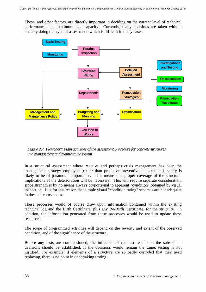
68 7 Engineering aspects of structure management
These, and other factors, are directly important in deciding on the current level of technical performance, e.g. maximum load capacity. Currently, many decisions are taken without actually doing this type of assessment, which is difficult in many cases. Basic Testing
Monitoring Routine
Inspection
Structure Rating
Repair Needs
Budgeting and Planning
Execution of Works
Management and Maintenance Policy
Optimisation
Detailed Assessment
Remediation Strategies
Investigations and Testing
Re-calculation
Monitoring
Remediation Techniques
Figure 25: Flowchart: Main activities of the assessment procedure for concrete structures in a management and maintenance system
In a structural assessment where reactive and perhaps crisis management has been the management strategy employed [rather than proactive preventive maintenance], safety is likely to be of paramount importance. This means that proper coverage of the structural implications of the deterioration will be necessary. This will require separate consideration, since strength is by no means always proportional to apparent "condition" obtained by visual inspection. It is for this reason that simple visual "condition rating" schemes are not adequate in these circumstances. These processes would of course draw upon information contained within the existing technical log and the Birth Certificate, plus any Re-Birth Certificate, for the structure. In addition, the information generated from these processes would be used to update these resources. The scope of programmed activities will depend on the severity and extent of the observed condition, and of the significance of the structure. Before any tests are commissioned, the influence of the test results on the subsequent decisions should be established. If the decisions would remain the same, testing is not justified. For example, if elements of a structure are so badly corroded that they need replacing, there is no point in undertaking testing.
Copyright fib, all rights reserved. This PDF copy of fib Bulletin 44 is intended for use and/or distribution only within National Member Groups of fib.
fib Bulletin 44: Concrete structure management: Guide to ownership and good practice 69
Two significantly different concepts may be adopted when designed sampling regimes to investigate the condition of a structure. These are hypothesis versus random sampling and testing. The former approach will generally be employed by an experienced investigator who, on the basis of an initial inspection, will generally be able to develop a view on the nature of the problems and deterioration processes affecting a structure. The investigator will then use targeted sampling and testing to validate and challenge this hypothesis. Such an approach will almost always be much more efficient and cost effective than any form of random sampling or testing. The scope of random sampling may be extended in the misguided belief that greater numbers of test results will automatically provide a more valid conclusion. This is not so. Sampling and testing, however comprehensive, cannot define the structure fully. It is generally better to target this effort on the basis of hypothesis sampling. It may be possible to restrict the scope of testing where the structure has performed well and has had appropriate professional input to its original design and construction. Additional assurance may be gained if the structure is one of many similar structures with a good service history. A prognosis upon future durability or for life-care plans will need data upon the condition and performance of the structure. The range of potential condition and performance tests is large, covering a wide range of cost and complexity. Some tests cause little disturbance to the structure itself, while others cause major disruption. The engineer should weigh up the advantages of proposed tests against the consequences and the costs. In some circumstances the cost of certain types of testing can be such that remedial action without testing provides a more economic solution (e.g. the provision of replacement ties within multi-leaf cladding panels). Generally, less testing will be needed the lower the level of performance required from the structure. The first stage in developing a test regime is to consider the minimum necessary. Further tests should be carried out only if the assessment of the first stage testing shows that a more advantageous course of action can be taken as a result. Caution needs to be exercised when relying on tests conducted previously by others, especially where results have been quoted in more general reports and only these reports are available for consideration and not the original data. It is important to check the validity of existing data before proceeding with further work that relies on this input. Clearly it is necessary to undertake an appropriate investigation and assessment of the structure to establish the mechanisms of deterioration which are active, as well as their relative importance. These processes allow a correct diagnosis of the problems affecting the structure to be made, so that an appropriate management strategy and suitable remediation options can be selected. This approach allows the underlying issues and problems to be addressed and just not the symptoms currently being manifested. In the area of structural assessment of both buildings and bridges, researchers continue to investigate non-destructive evaluations and testing (NDE and NDT) techniques. Although improvements have been made in this area no method has proven effective in all cases. Technologies used in the aerospace and aviation area are being explored for possible applications to concrete structures. Remote monitoring systems are also being explored that are programmed to call in when a problem is detected. These systems are likely to be reactive if they do not assess the needs or performance requirements placed upon the structure.
Copyright fib, all rights reserved. This PDF copy of fib Bulletin 44 is intended for use and/or distribution only within National Member Groups of fib.
70 7 Engineering aspects of structure management
In a number of countries engineers are looking into reliability based assessment of structures. These methods are being developed to improve the behaviour models and associated statistical descriptions for the resistance of older materials, create more accurate models of the structures ability to carry design loads or new loads and to derive more accurate probabilistic behaviour models for the assessment and rehabilitation of the structure. To date assessment of existing structure is typically still reliant on visual inspections by trained personnel. These inspections are very subjective, with the results obtained being found to vary from inspector to inspector. Work continues to improve the quality, accuracy and consistency of the inspection results obtained utilizing different management systems.
7.5 Overview of repair and remediation methods
In general, the choice of appropriate concrete repair and remediation method is a complex task and will depend on a number of factors. The concrete repair methods are described in various documents including: ACI 546R-96 “Concrete repair guide”, ACRA / CSIRO “Guide to concrete repair and protection” and the ICRI “Concrete repair manual”. An overview is given in Appendix B of the approaches used in the European Standards for the Repair and Protection of Concrete (EN 1504 -1, EN 1504 – 9 and drafts of prEN 1504 Parts 2 to 8). The series of EN 1504 standards set out the principles and methods of protection and repair which can be adopted. The principles and methods are divided into two groups: the first deals with defects in the concrete as a material and the second with reinforcement corrosion related defects. When choosing a repair or remediation technique the following criteria should be evaluated • Requirements defined by the owner • Remediation or repair assumptions • Experience and success of using the different remediation techniques available EN 1504-Part 9 outlines 6 different options that the owner may consider for addressing deterioration of a concrete structure: • Postpone the repair-work – but implement regular inspection of the structure and
monitoring of the degradation process, but only if the data or information gathered contributes directly to the decision making procedure. A component of this management option might be the introduction of restrictions on the usage of the structure.
• Re-evaluate and recalculate the structural load capacity or other critical performance characteristic
• Make efforts to avoid further degradation • Undertake structural strengthening / restoration and aesthetic upgrading • Reconstruction of selected components or the complete structure • Demolition
Copyright fib, all rights reserved. This PDF copy of fib Bulletin 44 is intended for use and/or distribution only within National Member Groups of fib.
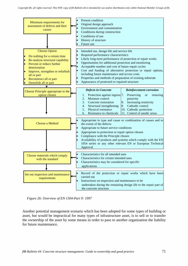
fib Bulletin 44: Concrete structure management: Guide to ownership and good practice 71
Minimum requirements for assessment of defects and their
causes
• Present condition • Original design approach • Environment and contamination • Conditions during construction
• Conditions of use • History of structure • Future use
Choose Option
• Do nothing for a certain time • Re-analyse structural capability • Prevent or reduce further
deterioration • Improve, strengthen or refurbish
all or part • Reconstruct all or part • Demolish all or part
• Intended use, design life and service life • Required performance characteristics • Likely long-term performance of protection or repair works • Opportunities for additional protection and monitoring • Acceptable number and cost of future repair cycles • Cost and funding of alternative protection or repair options,
including future maintenance and access costs • Properties and methods of preparation of existing substrate • Appearance of protected or repaired structure
Choose Principle appropriate to the option chosen
Defects in Concrete
1. Protection against ingress2. Moisture control 3. Concrete restoration 4. Structural strengthening 5. Physical resistance 6. Resistance to chemicals
Reinforcement corrosion
7. Preserving or restoring passivity
8. Increasing resistivity 9. Cathodic control 10. Cathodic protection 11. Control of anodic areas
Choose a Method • Appropriate to type and cause or combination of causes and to
the extent of the defects • Appropriate to future service conditions
• Appropriate to protection or repair option chosen • Compliance with the Principle chosen • Availability of products and systems which comply with the EN
1054 series or any other relevant EN or European Technical Approval
Choose materials which comply with the standard
• Characteristics for all intended uses • Characteristics for certain intended uses • Characteristics may be considered for specific
applications
Set out inspection and maintenance requirements
• Record of the protection or repair works which have been carried out
• Instructions on inspection and maintenance to be undertaken during the remaining design life to the repair part of
the concrete structure
Figure 26: Overview of EN 1504-Part 9: 1997
Another potential management scenario which has been adopted for some types of building or asset, but would be impractical for many types of infrastructure asset, is to sell or to transfer the ownership of the asset by some means in order to pass to another organisation the liability for future maintenance.
Copyright fib, all rights reserved. This PDF copy of fib Bulletin 44 is intended for use and/or distribution only within National Member Groups of fib.
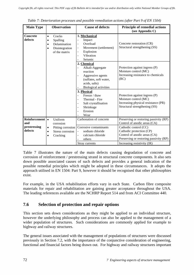
72 7 Engineering aspects of structure management
Table 7: Deterioration processes and possible remediation actions (after Part 9 of EN 1504)
Main Type Observation Cause of defects Principle of remedial actions (see Appendix C)
1. Mechanical - Impact - Overload - Movement (settlement) - Explosion - Vibration - Seismic
Concrete restoration (CR) Structural strengthening (SS)
2. Chemical - Alkali-Aggregate
reaction - Aggressive agents
(sulfates, soft water, acids, salts)
- Biological activities
Protection against ingress (P) Moisture control (MC) Increasing resistance to chemicals (RC)
Concrete defects
• Cracks • Spalling • Delamination • Disintegration
of the matrix
3. Physical - Freeze / thaw - Thermal - Fire - Salt crystallisation - Shrinkage - Erosion - Wear
Protection against ingress (P) Moisture control (MC) Increasing physical resistance (PR) Structural strengthening (SS)
Carbonation of concrete Preserving or restoring passivity (RP)Control of anodic areas (CA)
Corrosive contaminants - sodium chloride - calcium chloride - others
Cathodic control (CC) Cathodic protection (CP) Control of anodic areas (CA) Preserving or restoring passivity (RP)
Reinforcement and prestressing defects
• Uniform corrosion
• Pitting corrosion • Stress corrosion • Cracking
Stray currents Increasing resistivity (IR) Table 7 illustrates the nature of the main defects causing degradation of concrete and corrosion of reinforcement / prestressing strand in structural concrete components. It also sets down possible associated causes of such defects and provides a general indication of the possible remedial principles which might be adopted in these circumstances. It adopts the approach utilised in EN 1504: Part 9, however it should be recognised that other philosophies exist. For example, in the USA rehabilitation efforts vary in each State. Carbon fibre composite materials for repair and rehabilitation are gaining greater acceptance throughout the USA. The leading references available are the NCHRP Report 514 and from ACI Committee 440.
7.6 Selection of protection and repair options
This section sets down considerations as they might be applied to an individual structure, however the underlying philosophy and process can also be applied to the management of a wider population of structures. Such considerations are commonly applied for example to highway and railway structures. The general issues associated with the management of populations of structures were discussed previously in Section 7.2, with the importance of the conjunctive consideration of engineering, functional and financial factors being drawn out. For highway and railway structures important
Copyright fib, all rights reserved. This PDF copy of fib Bulletin 44 is intended for use and/or distribution only within National Member Groups of fib.
fib Bulletin 44: Concrete structure management: Guide to ownership and good practice 73
issues can include budgets, phasing of works and potential linkages between the works proposed on an individual structure and the operation of the wider network. The selection of remediation options requires consideration to be given to a wide range of influencing factors, including those listed below. It will be noted that factors and actions taken much earlier in the overall process of investigating and assessing the structure can have a profound impact upon remediation decisions. Critical factors may include: • The importance of correct diagnosis. • The nature of the problems to be overcome. • The time to when intervention will be required and / or the required residual life. • Whether structural or non-structural issues are to be addressed. • Load take-up and sharing mechanisms active within the structure. • The required service life of the repair / remediation materials and repair / remediation
methods, when applied to the structure as apposed to accelerated laboratory performance tests (which often provide useful comparative indications of performance and durability).
• Maintenance or intervention works needed and how these might be undertaken. • Design
o structural o non-structural o materials o non-engineering / non-technical issues
• Selection of options. • Planning and timing / phasing of intervention activities. • Execution of works. • Supervision of all processes including design, specification and execution. • Verification of effectiveness of repair / remediation and the quality achieved. • Monitoring of performance: various methods may be employed [Refs]. • Evaluate results achieved by intervention and plan future actions. • Maintenance or post-intervention life-care actions. • Costs (may be other than for engineering and technical issues). Various forms of value judgement and / or scoring systems exist to help evaluate the influence of contributing parameters, including technical and non-technical requirements, upon the selection of an appropriate remediation option. The process is commonly referred to as multi-criteria decision making and various tools 2 have been developed to perform the analyses. Most tools use weighting factors to reflect the relative importance of each criterion. These processes seek to bring together in an integrated decision process factors such as whole-life or residual-life cost, functional performance, as well as political and other social issues. Decision support tools are commonly required as the
2 The methodologies which exist include the Quality Function Deployment (QFD), the Multiple-Attribute Decision Aid (MADA) and Risk Analysis methods. A number of these were utilised in the LIFECON project (Life Cycle Management of Concrete Infrastructures for Improved Sustainability). The Life Cycle Management System developed in the LIFECON project provided a methodology to organise and implement all the activities related to maintenance, repair, rehabilitation and replacement of concrete assets in an optimised way taking into account all necessary aspects of life cycle planning. Further details about the use of these methodologies in the LIFECON project outputs [See Section 13, References relating to Durability, service life design and through-life performance].
Copyright fib, all rights reserved. This PDF copy of fib Bulletin 44 is intended for use and/or distribution only within National Member Groups of fib.
74 7 Engineering aspects of structure management
task can become complex, laborious and expensive if a large number of steps and factors are involved in the evaluation of the potential alternatives (LIFECON reports). Clearly these activities need to form part of a wider process involving the owner to establish which parameters should be considered (i.e. are important to the particular organisation and assets involved), the value criteria to be employed and how the outcomes will be utilised and implemented. See previous discussion in Section 4.
7.7 Performance indicators
A methodology for selecting and monitoring methods for the protection and repair of concrete structures
This section presents an example of a simplified methodology for selecting and subsequently monitoring the performance in service of methods for the protection and repair of concrete structures. The development and definition of appropriate Performance Indicators (see Box 3: Performance Evaluation: Stage 5) requires consideration of a range of issues such as: • The condition of the structure / substrate prior to the concrete protection and repair
intervention(s) being made. This may need to be considered at both component and overall structure level.
• The nature of the loading and environmental conditions to which the structure and the associated repair or protection intervention(s) will be exposed.
• The deterioration mechanisms affecting the original structure and potentially the concrete protection and repair method(s) to be employed.
• Test or investigation procedures which are sensitive to the mechanism(s) of deterioration concerned and hence can reliably detect/monitor these changes and effects arising over time.
The methodology is based on the definition of requirements, R, for the protection and repair intervention and / or the repaired structure. These are developed via a series of Performance Indicators, PI, that are scored from 4 (bad) to 1 (good) for the particular criterion. A high score indicates a poor performance and a low score (1) indicates good performance. An overall assessment is given by calculation of a Repair Performance Index, RPI, which is obtained by addition of the individual PI multiplied by their Relative Importance, ImPI. The RPI is the sum of the individual Performance Indicators multiplied by their respective values of Relative Importance (weight).
∑=n
1PIIm.PIRPI
Where n is the number of PI used to qualify a particular repair or intervention method. The ImPI values are expected to be different for each PI, and overall they total unity (1). The Figure 27 shows hypothetical plots for the evolution of the RPI value with time. The requisite data needed to make the evaluations is obtained by means of periodical inspections, monitoring and / or testing. In addition to the evolution of RPI with time being expressed as a score which increases with time from a low number to a higher value (maximum of 4 in the scale range illustrated in the example given below for patch repair), it can also be normalized as a percentage of the
Copyright fib, all rights reserved. This PDF copy of fib Bulletin 44 is intended for use and/or distribution only within National Member Groups of fib.
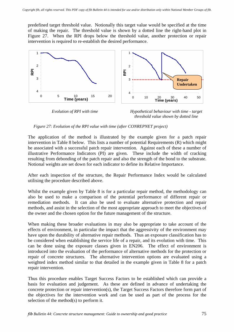
fib Bulletin 44: Concrete structure management: Guide to ownership and good practice 75
predefined target threshold value. Notionally this target value would be specified at the time of making the repair. The threshold value is shown by a dotted line the right-hand plot in Figure 27. When the RPI drops below the threshold value, another protection or repair intervention is required to re-establish the desired performance.
1
2
3
40 5 10 15 20
Time (years)
RPI
1
2
3
40 10 20 30 40 50
Time (years)
RPI
Evolution of RPI with time
Hypothetical behaviour with time - target threshold value shown by dotted line
Figure 27: Evolution of the RPI value with time (after CONREPNET project)
The application of the method is illustrated by the example given for a patch repair intervention in Table 8 below. This lists a number of potential Requirements (R) which might be associated with a successful patch repair intervention. Against each of these a number of illustrative Performance Indicators (PI) are given. These include the width of cracking resulting from debonding of the patch repair and also the strength of the bond to the substrate. Notional weights are set down for each indicator to define its Relative Importance. After each inspection of the structure, the Repair Performance Index would be calculated utilising the procedure described above. Whilst the example given by Table 8 is for a particular repair method, the methodology can also be used to make a comparison of the potential performance of different repair or remediation methods. It can also be used to evaluate alternative protection and repair methods, and assist in the selection of the most appropriate approach to meet the objectives of the owner and the chosen option for the future management of the structure. When making these broader evaluations in may also be appropriate to take account of the effects of environment, in particular the impact that the aggressivity of the environment may have upon the durability of alternative repair methods. Thus an exposure classification has to be considered when establishing the service life of a repair, and its evolution with time. This can be done using the exposure classes given in EN206. The effect of environment is introduced into the evaluation of the performance of alternative methods for the protection or repair of concrete structures. The alternative intervention options are evaluated using a weighted index method similar to that detailed in the example given in Table 8 for a patch repair intervention. Thus this procedure enables Target Success Factors to be established which can provide a basis for evaluation and judgement. As these are defined in advance of undertaking the concrete protection or repair intervention(s), the Target Success Factors therefore form part of the objectives for the intervention work and can be used as part of the process for the selection of the method(s) to perform it.
Repair Undertaken
Copyright fib, all rights reserved. This PDF copy of fib Bulletin 44 is intended for use and/or distribution only within National Member Groups of fib.
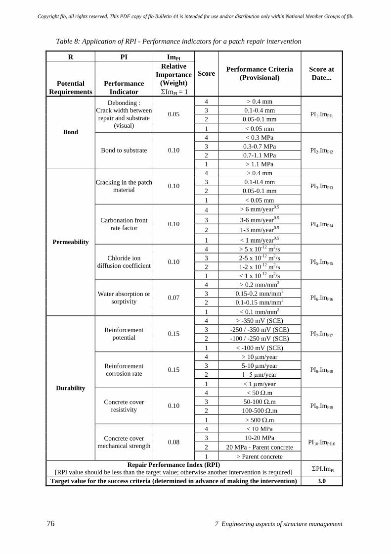
76 7 Engineering aspects of structure management
Table 8: Application of RPI - Performance indicators for a patch repair intervention
R PI ImPI
Potential Requirements
Performance Indicator
Relative Importance
(Weight) ΣImPI = 1
Score Performance Criteria (Provisional)
Score at Date...
4 > 0.4 mm 3 0.1-0.4 mm 2 0.05-0.1 mm
Debonding : Crack width between repair and substrate
(visual)
0.05
1 < 0.05 mm
PI1.ImPI1
4 < 0.3 MPa 3 0.3-0.7 MPa 2 0.7-1.1 MPa
Bond
Bond to substrate 0.10
1 > 1.1 MPa
PI2.ImPI2
4 > 0.4 mm 3 0.1-0.4 mm 2 0.05-0.1 mm
Cracking in the patch material 0.10
1 < 0.05 mm
PI3.ImPI3
4 > 6 mm/year0.5 3 3-6 mm/year0.5 2 1-3 mm/year0.5
Carbonation front rate factor 0.10
1 < 1 mm/year0.5
PI4.ImPI4
4 > 5 x 10-12 m2/s 3 2-5 x 10-12 m2/s 2 1-2 x 10-12 m2/s
Chloride ion diffusion coefficient 0.10
1 < 1 x 10-12 m2/s
PI5.ImPI5
4 > 0.2 mm/mm2 3 0.15-0.2 mm/mm2 2 0.1-0.15 mm/mm2
Permeability
Water absorption or sorptivity 0.07
1 < 0.1 mm/mm2
PI6.ImPI6
4 > -350 mV (SCE) 3 -250 / -350 mV (SCE) 2 -100 / -250 mV (SCE)
Reinforcement potential 0.15
1 < -100 mV (SCE)
PI7.ImPI7
4 > 10 µm/year 3 5-10 µm/year 2 1−5 µm/year
Reinforcement corrosion rate 0.15
1 < 1 µm/year
PI8.ImPI8
4 < 50 Ω.m 3 50-100 Ω.m 2 100-500 Ω.m
Concrete cover resistivity 0.10
1 > 500 Ω.m
PI9.ImPI9
4 < 10 MPa 3 10-20 MPa 2 20 MPa - Parent concrete
Durability
Concrete cover mechanical strength 0.08
1 > Parent concrete
PI10.ImPI10
Repair Performance Index (RPI) [RPI value should be less than the target value; otherwise another intervention is required] ΣPI.ImPI
Target value for the success criteria (determined in advance of making the intervention) 3.0
Copyright fib, all rights reserved. This PDF copy of fib Bulletin 44 is intended for use and/or distribution only within National Member Groups of fib.
fib Bulletin 44: Concrete structure management: Guide to ownership and good practice 77
8 Process management 8.1 Establishing the professional team
This section sets down considerations as they might be applied to an individual structure, however the underlying philosophy and process can also be applied to the management of a wider population of structures. It is acknowledged that the owner can greatly improve the likelihood of achieving the value they seek from a structure or facility by being intimately and effectively involved in the definition of performance requirements at the start of the construction procurement process. Clear vision and direction are important elements for success. The principles of what follows are equally applicable to new construction projects and to repair and reconstruction projects, where durability considerations apply to both the new and existing parts of the structure. The overall relationships are illustrated in Figure 1. The sophistication and complexity of the system set up to monitor performance of a structure will depend, amongst other things, on the number of structures in the population for which the owner is responsible as well as the value of the individual structures. To achieve these goals the owner will usually need the support of a team of professional advisers, which could comprise architects, engineers, contractors or others depending upon the nature of the task to be undertaken and the expertise held by the owner. Together they should be able to address the various technical and process matters relating to design, construction, maintenance and end of life issues that may arise. It is possible that some, maybe all, of the expertise required will reside within the owner’s organisation. Key considerations in setting up the professional team may include: • How the owner can engage effectively with their supporting professional team to enable
them to achieve functional, durable buildings and infrastructure providing value for money in relation to the goals of the business or organisation concerned.
• What information and direction is needed by the supporting professional team (i.e. the brief they receive from the owner).
A critical issue for repair and maintenance works on concrete structures can be the role of specialist contractors who offer proprietary systems or techniques for such works. In these circumstances there may be an absence of independent specialist knowledge or expertise about these techniques in the proposed team, unless the specialist is brought into the team at an early stage (perhaps through a Partnering arrangement).
8.2 Scenario selection
It is envisaged that successful implementation of the activities associated with the maintenance and remediation in concrete structures will involve three main steps: • A process for selecting suitable repair or remediation treatments / intervention options for
the circumstances relating to the particular facility under consideration. This would entail evaluation, using some form of scoring, against a range of technical (functional) and non-
Copyright fib, all rights reserved. This PDF copy of fib Bulletin 44 is intended for use and/or distribution only within National Member Groups of fib.
78 8 Process management
technical requirements to judge their basic suitability against pre-defined criteria established for the particular circumstances under consideration.
• A process for developing a range of potential scenarios for managing the remaining-life performance of the facilities concerned. This step considers how the suitable treatments / intervention options can be employed either on their own or in combination with others to produce practical scenarios for managing through-life performance. A high degree of technical knowledge and experience is likely to be required to perform this task satisfactorily.
• A process for establishing which the most appropriate management scenario is. Each scenario would then need to be evaluated to establish which the most appropriate approach was. This would need to consider both technical and non-technical functional requirements, together with their anticipated cost (remaining-life basis) and environmental (sustainability) impact.
In these processes due recognition needs to be given to the various requirements and constraints affecting not only the operation of the asset, but also the implications for the wider circumstances within which it resides. For example, the operational or environmental constraints affecting inspection planning and maintenance work scheduling for jetty and marine structures include factors such as tidal variations or berthing schedules of ships, heavy seasonal rains such as monsoons or typhoons, prevailing wind directions etc. It should also be understood that at such times access may be dangerous and that it may not be possible to apply some concrete protection and repair products under such aggressive conditions, nor might they be compatible with the condition of the substrate at such times. A performance based or service life approach must necessarily take these into account as these constraints affect not only the technical aspects but also the residual-life costs of maintenance, remediation and operation, as well as the processes and operational effectiveness of the overall facility. The use of performance indicators, that is the simplified methodology for selecting and monitoring methods for the protection and repair of concrete structures described in Section 7.6, may be of assistance as a decision support tool. Once these evaluations have been made and the appropriate decisions made, the works then move to the execution phase in which the repairs or other specified actions are implemented. In this context management scenarios are envisaged to be a form of story-line (a time-line narrative) outlining what actions are expected to be taken over the coming years, and at approximately what times in the future, to maintain or repair the concrete structure or facility concerned. Clearly these plans would need to be developed with an adequate understanding of the future objectives of the business or the service requirements of the organisation concerned. Timing of prospective interventions would need to take account of any budgetary or other constraints to which the owner was subject. In doing this it should be recognised that the timing of future actions is based on estimates, made via models or other means, of when the structure will reach a specified condition. This needs to be incorporated within monitoring and inspection regimes, rather than relying on the estimated timing of when that condition will occur.
Copyright fib, all rights reserved. This PDF copy of fib Bulletin 44 is intended for use and/or distribution only within National Member Groups of fib.
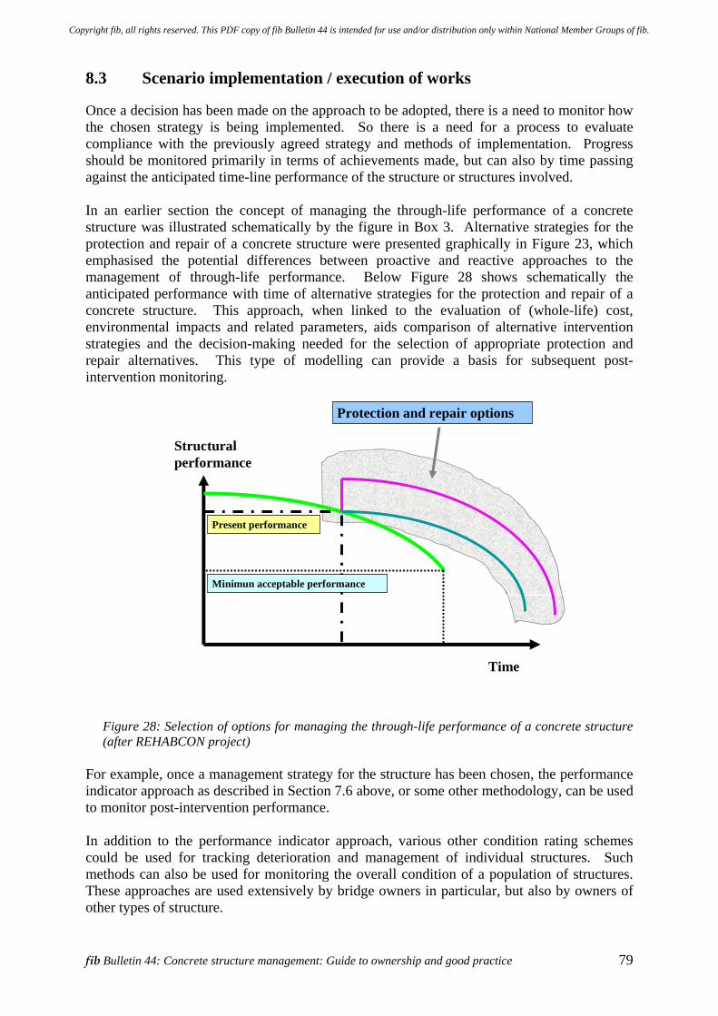
fib Bulletin 44: Concrete structure management: Guide to ownership and good practice 79
8.3 Scenario implementation / execution of works
Once a decision has been made on the approach to be adopted, there is a need to monitor how the chosen strategy is being implemented. So there is a need for a process to evaluate compliance with the previously agreed strategy and methods of implementation. Progress should be monitored primarily in terms of achievements made, but can also by time passing against the anticipated time-line performance of the structure or structures involved. In an earlier section the concept of managing the through-life performance of a concrete structure was illustrated schematically by the figure in Box 3. Alternative strategies for the protection and repair of a concrete structure were presented graphically in Figure 23, which emphasised the potential differences between proactive and reactive approaches to the management of through-life performance. Below Figure 28 shows schematically the anticipated performance with time of alternative strategies for the protection and repair of a concrete structure. This approach, when linked to the evaluation of (whole-life) cost, environmental impacts and related parameters, aids comparison of alternative intervention strategies and the decision-making needed for the selection of appropriate protection and repair alternatives. This type of modelling can provide a basis for subsequent post-intervention monitoring.
Present performance
Time
Structuralperformance
Protection and repair options
Minimun acceptable performance
Figure 28: Selection of options for managing the through-life performance of a concrete structure (after REHABCON project)
For example, once a management strategy for the structure has been chosen, the performance indicator approach as described in Section 7.6 above, or some other methodology, can be used to monitor post-intervention performance. In addition to the performance indicator approach, various other condition rating schemes could be used for tracking deterioration and management of individual structures. Such methods can also be used for monitoring the overall condition of a population of structures. These approaches are used extensively by bridge owners in particular, but also by owners of other types of structure.
Copyright fib, all rights reserved. This PDF copy of fib Bulletin 44 is intended for use and/or distribution only within National Member Groups of fib.
80 8 Process management
Other considerations which might be taken into account in this process include the: • Nature of the condition rating scheme to be used, including its advantages and limitations. • Types of contract employed and the balance of risk and reward for the parties involved.
These arrangements might be on the basis of forming a partnership between the owner and the principal service providers (consultants, repair specialist, material suppliers, etc) or this could involve competition in respect of the technical solution to be adopted and / or the service provider delivering it.
• Supervision arrangements. • Future monitoring and assessment procedures.
8.4 Quality planning and verification during execution of works
8.4.1 The role of the project specification
This section explores the role within the project specification of quality planning and processes for verification during the execution of works as a means of producing predictably durable concrete structures. Many infrastructure owners would like a greater degree of certainty that their major concrete structures will achieve their intended design life, which may be 50 or 100 years, or even longer (refer Box 1). High quality durable concrete structures can be created, but this is not always achieved because of problems which can arise with the concreting processes. In some unfortunate circumstances initial indications of durability problems, such as reinforcement corrosion, may occur after perhaps as little as 10 to 15 years. To achieve a greater degree of certainty, owners and members of their professional team need to take more interest in what is being created and exert more influence over the processes being employed. It may be that they should seek better verification of the concrete production and execution processes. It is the tender and contract documents which set the standards under which these processes will be carried out. Thus attention needs to be given to these matters in order to achieve tangible improvements in the certainty of the durability of a concrete structure being built. Within the tender documents design codes and standards for concrete structures are typically used to define the minimum required properties of the concrete in the structure, as well as providing general rules for the production of concrete and the execution of concreting processes. However, these codes do not specify in detail how the critical concreting processes will be carried out. The project specification must incorporate all the measures and requirements necessary (as contained in relevant design codes and standards, together with any supplementary documents) to ensure that all structural components will be constructed in a manner to achieve the specified properties in the finished concrete. In addition the project specification needs to call for adequate verification during concreting operations to ensure that specified process control procedures have been carried out. Under a contract utilising normal quality procedures it is the contractor and his subcontractors who develop the detailed process control and verification procedures. However, the contractual arrangements may require or allow the quality planning or verification functions to be carried out by the owner or his professional team (a formal application of the traditional method) or by an independent consultant or contractor.
Copyright fib, all rights reserved. This PDF copy of fib Bulletin 44 is intended for use and/or distribution only within National Member Groups of fib.
fib Bulletin 44: Concrete structure management: Guide to ownership and good practice 81
Whichever of the preceding methods is used, the key to successful quality management is for the project specification to incorporate an adequate set of quality plan requirements, so that the tenderers must do the necessary pre-construction planning to ensure that their tender proposals meet these requirements and are realistically priced. To achieve the specified quality, critical preparations should be undertaken at an appropriate time (essentially as early as practicable) and with sufficient monies allowed in the contract to do the work in an acceptable manner and to a satisfactory standard. This philosophy also needs to be applied as early as possible and prior to inviting tenders, that is during the process of selecting potential tenderers and when preparing a select list of potential tenderers for a project. These considerations may have a bearing upon the contractual arrangements put into place between the owner or his professional team / the constructor or repair specialist. Early involvement of professional team / the constructor or repair specialist has been shown to be advantageous and are adopted by various national authorities, such as The Highways Agency in the UK and similar public bodies elsewhere. It has been recognised that conventional approaches to quality management, which have relied upon “paper” verification by means of “box-ticking” procedures, have not always delivered in the field the quality of concrete and the durability desired for a finished concrete structure. This can be particularly important where construction circumstances may be especially difficult, the operating environment severe or the durability requirements demanding. In these circumstances reliance upon “box-ticking” procedures can be misguided if this directs efforts away from the practical steps which are needed to achieve the desired quality in the final structure. In extreme circumstances these practices might even be considered to contribute negatively to the quality achieved in the finished product. Thus “box ticking” in itself cannot be said to contribute to the quality of construction achieved on site. Difficulties can arise where individuals are exposed to conflicting priorities, which may make it inappropriate for individuals to be allowed to self-regulate for quality, or other critical requirement. The adoption of a risk based approach / methodology to quality management potentially provides a way forward and is being adopted by major contractors to supplement the basic requirements of the ISO 9001 system, which has been adopted world-wide. Both ISO 9001 and more project-specific risk-based methodologies can be used to identify potential non-conformances which could develop in the contract works, either immediately or over a longer term; as would be the case for durability related failures. The production of such non-conformances is most often associated with faulty or inadequate processes of construction, and therefore will be due to either: • faults or inadequacies in the procedures used for the controlling and verifying of those
processes • failure to comply with procedures which are adequate. Effective quality planning or risk management should ensure that the relevant procedures incorporate preventive actions specifically designed to eliminate or minimise the identified problems or risks, thereby increasing the certainty of achieving the desired outcome (a sufficiently durable concrete structure).
Copyright fib, all rights reserved. This PDF copy of fib Bulletin 44 is intended for use and/or distribution only within National Member Groups of fib.
82 8 Process management
Implementation may require, where appropriate, the adoption of additional controls, such as closer site or process supervision. These preventive actions might be concerned with: • The provision of fresh concrete, which is the design of the mix and batching procedures. • Activities associated with the creation of the formed concrete structure, such as the
provision of formwork manufactured to appropriate tolerances, achieving an adequate and compliant depth of cover, etcetera.
• Placing of the fresh concrete and its subsequent curing. • The properties of the hardened concrete, particularly those influencing durability. It is the responsibility of the owner's professional team to produce a project specification which will ensure that the proposed structure will be constructed in a manner which ensures that the required durability and service life will be achieved. All necessary pre-contract investigations and trials must be provided for, or taken account of, in the project specification. Allied to this must be the recognition that people are central to achieving quality, irrespective of what quality management system or risk management approach is being used. Accordingly training and skills are critical to achieving quality in the field. People need to understand not only what they have to do and why, but they also need to be fully aware of the consequences of not conforming to the stated requirements. This appreciation takes time and can only be driven by education. In this way workers will hopefully act in a responsible manner, rather than just adhering to the (minimum) formal requirements of the quality system. Future developments in the field of Performance Based Building (PBB) could impact on both QA and QC activities. For example, consideration of how a structure is to be put together will need proper attention to ensure delivery of the specified performance properties. The introduction of PBB may force us to rethink current quality management approaches, the relation between workmanship and performance properties, as well as how non-conformances are resolved. In all of this the conditional link between design, execution and durability needs to be recognised. Clearly it is also essential that the project specification should be prepared by experienced engineers with due consideration of the construction process. Specifications should allow compliance for reasonable effort being made at site level, recognising natural and physical limitations such as the shape of the structural component, mix design, reinforcement details etc. There is also the need to recognise the difference between the durability of concrete as a material and the durability of a concrete structure, as illustrated by the example of the Progreso Piers portrayed previously in Figure 5.
8.4.2 The need for revised quality management concepts
The durability of concrete is greatly influenced by the processes of placing, compaction and curing of the concrete. These processes are governed by workmanship, with the attendant deviations from the “nominal” which experience suggests are very difficult to avoid. This emphasises the vital role of training and qualification not only of site workers, but also of designers, detailers and specifiers. These potential difficulties justify the requirement for strict procedures and the role of independent inspectors in durability critical situations. Thus the durability-determining properties of the hardened concrete can be greatly affected by “uncontrolled and unrecorded” variations in the concrete batching process, and also by non-conformances in the placing, compaction and curing processes. In practice these can only be
Copyright fib, all rights reserved. This PDF copy of fib Bulletin 44 is intended for use and/or distribution only within National Member Groups of fib.
fib Bulletin 44: Concrete structure management: Guide to ownership and good practice 83
confirmed by direct observation during the process and by appropriate in-situ testing of durability related properties. Although equipment is available to perform an analysis of the composition of fresh concrete, generally there has not been a widespread take-up of the technology and hence there is currently very little requirement for its use. These process non-conformances can only be properly identified, and assessed, by “continuous monitoring” of the durability critical execution processes. Such continuous monitoring requires suitable expert inspectors to be in the right place at the right time. With appropriate resources they will be able to verify (and report on the fact) that the right things have, or have not, been done. This procedure could be driven by a risk-based approach. The production and execution processes must be carried out according to pre-planned procedures which explain what the critical processes are. These procedures also need to establish when, where, by whom and how the procedures will be carried out. Of these perhaps the most important issue is how the procedures will be implemented. These procedures should form the core of the contractor's quality plan, which in turn should meet all the quality plan requirements defined by the project specification. Quality auditors, with adequate relevant construction experience, should verify that this has been done before the contractor commits resources to the physical realisation of the particular concrete component or asset. Ideally quality auditors should be independent, but may be part of the contractor’s team as long as their freedom to discharge their duties is not constrained in any way. Owners and their professional team need to appreciate that some of the common concepts and practices of quality management may need to be enhanced in certain circumstances. Tender and contract documents need to ensure that quality requirements (eg. durability) will not be compromised. Furthermore, pricing schedules and project cost estimates need to allow for the provision of the resources required for the proper planning and effective monitoring of critical execution processes. Thus close monitoring and control is required for site execution processes where the risks of non-compliance are significant. It is only in this way that the owner can have genuine assurance that the required properties will actually be achieved in the built structure. Contrary to long-established construction contract practice, the durability of a concrete structure cannot be satisfactorily verified by conventional methods of product inspection and testing. For example, routine testing is normally done on separately prepared samples which are supposed to represent the hardened concrete in the structure. Notionally these test results show the potential properties of the concrete in the structure, if it is cast and cured (and tested) under the same conditions as the test samples. This is seldom, if ever, the case and the difference between potential and actual properties may be considerable. These differences could lead to the contractual acceptance of structural concrete which, in fact, does not comply with the requirements and should therefore not be accepted. Such product tests form the core of the typical industry-accepted quality-management system. However, for site-placed concrete non-conformances in the batching process and / or the execution processes can have a profound and debilitating effect on the potential durability of the concrete in the structure. Unfortunately this effect is not generally identified by routine product testing programmes employed during construction. The concrete in the test sample may have very different properties, particularly in relation to long-term durability, to that of the concrete in the structure which it is supposed to represent. In many situations non-conformances in process control go unrecognised and unreported; and so can the resulting
Copyright fib, all rights reserved. This PDF copy of fib Bulletin 44 is intended for use and/or distribution only within National Member Groups of fib.
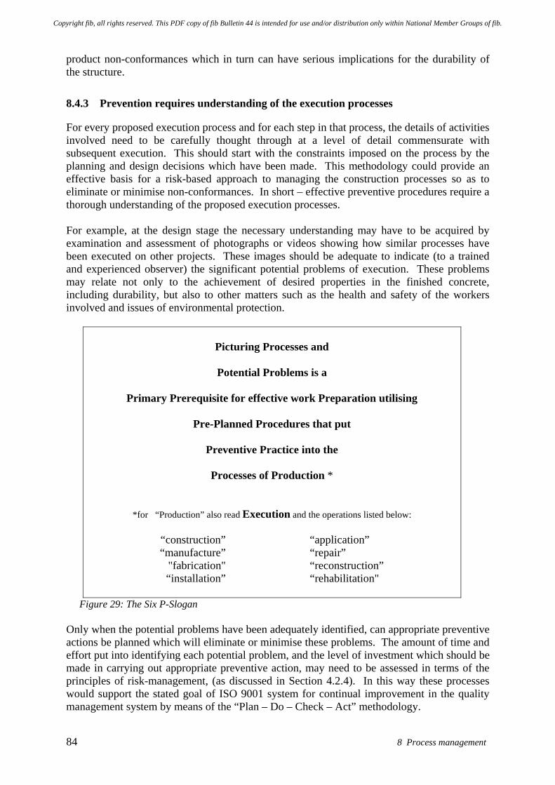
84 8 Process management
product non-conformances which in turn can have serious implications for the durability of the structure.
8.4.3 Prevention requires understanding of the execution processes
For every proposed execution process and for each step in that process, the details of activities involved need to be carefully thought through at a level of detail commensurate with subsequent execution. This should start with the constraints imposed on the process by the planning and design decisions which have been made. This methodology could provide an effective basis for a risk-based approach to managing the construction processes so as to eliminate or minimise non-conformances. In short – effective preventive procedures require a thorough understanding of the proposed execution processes. For example, at the design stage the necessary understanding may have to be acquired by examination and assessment of photographs or videos showing how similar processes have been executed on other projects. These images should be adequate to indicate (to a trained and experienced observer) the significant potential problems of execution. These problems may relate not only to the achievement of desired properties in the finished concrete, including durability, but also to other matters such as the health and safety of the workers involved and issues of environmental protection.
Picturing Processes and
Potential Problems is a
Primary Prerequisite for effective work Preparation utilising
Pre-Planned Procedures that put
Preventive Practice into the
Processes of Production *
*for “Production” also read Execution and the operations listed below:
“construction” “application” “manufacture” “repair” "fabrication" “reconstruction” “installation” “rehabilitation"
Figure 29: The Six P-Slogan
Only when the potential problems have been adequately identified, can appropriate preventive actions be planned which will eliminate or minimise these problems. The amount of time and effort put into identifying each potential problem, and the level of investment which should be made in carrying out appropriate preventive action, may need to be assessed in terms of the principles of risk-management, (as discussed in Section 4.2.4). In this way these processes would support the stated goal of ISO 9001 system for continual improvement in the quality management system by means of the “Plan – Do – Check – Act” methodology.
Copyright fib, all rights reserved. This PDF copy of fib Bulletin 44 is intended for use and/or distribution only within National Member Groups of fib.
fib Bulletin 44: Concrete structure management: Guide to ownership and good practice 85
Figure 29 - the Six P-Slogan – illustrates simplistically the principles of preventive action. These issues are addressed in quality standards and guides, with the overall focus and goal being to achieve customer satisfaction by preventing non-conformance at all stages from design through to the servicing of the “product”. "Customer satisfaction" cannot be provided without effective verification that the specified technical requirements have actually been achieved. For example, the owner needs assurance that the properties of the hardened concrete surface of the completed structure, that is the 50mm (say) thickness of cover concrete which provides protection against corrosion of the steel reinforcing bars, has consistently achieved (or will achieve) the specified minimum durability in all critical locations on site. In order to make the established quality standards, design codes and standards for concrete structures work effectively for the ultimate customer (the owner), an interpretive document needs to be prepared and incorporated in the project specification. This document is the project execution specification, which is developed from the Execution Standard for Concrete Structures as explained in Appendix G. The project execution specification must ensure that the process control requirements are effectively integrated with the specified technical requirements, including those of the relevant design codes and standards for concrete structures. Thus if effective quality management is to be achieved in today's construction contracts, the requirements must be clearly specified. Furthermore, potential contractors and sub-contractors must be fully aware of, and acknowledge these requirements. They must also be assured that the cost of meeting these requirements will be met in full in the overall price paid by the owner. All these challenges must therefore be addressed effectively, not only in the quality plan requirements of the project specification, but also in the tender and contract documents under the framework of a project quality plan (PQP). The PQP should address or refer to: objectives and criteria applicable to the project, organisational structure, technical and organisational working methods and procedures, lines of communication, tasks and responsibilities, quality management measures in case of outsourcing / subcontracting of activities, key personnel involved and handling of non-conformances. Pending the nature of the project and the type of contract, each development phase has a plan or the plan may cover a number of phases. Coherence and transfer of information and/ or instructions between phases is essential. For non standard and / or complicated projects a project specific risk analysis should be conducted to define issues to be addressed specifically in the PQP. Further details on aspects of these matters and observations are illustrated in Appendix G by reference to European and international standards for concrete and concrete structures. Overall it would be valuable if: • Codes and standards documents relating to the design, materials and execution of concrete
structures were better integrated and consistent. Work continues in this regard. • Construction professionals utilise these codes and other available guidance to create
adequate quality management systems that facilitate the specification and delivery of the desired through-life performance of the resulting structure.
Copyright fib, all rights reserved. This PDF copy of fib Bulletin 44 is intended for use and/or distribution only within National Member Groups of fib.
86 8 Process management
Owners with ongoing programmes of construction works could potentially benefit from partnering arrangements and initiatives such as early contractor involvement. Construction professionals would potentially benefit from the feedback upon through-life performance gained from individual projects and to capture this in a continuous learning and improvement process.
8.4.4 Project quality plan - Illustration of contents
The preparation of a project quality plan, including subsequent review and adjustment during the progress of the works, will assist in the overall process of risk management and achievement of owner requirements. The project quality plan needs input from all parties, including the owner, the professional team and the constructor / repair specialist depending upon the nature of the contractual relationships and the works to be undertaken. In the design and construction phase a project quality plan would usually be expected to address items such as: • Introduction: Description of the project, quality objectives in general, authorisation,
distribution and revisions of the PQP, abbreviations, references. • Project Parameters: Contractual and financial matters, project data, insurances, bonds,
guarantees and insurances, invoicing, project evaluation, owner and stakeholder satisfaction, defect liability period.
• Organisational Set-up: Project organisation, procurement and logistics, consultants / contractors, responsibilities, key personnel, interface management, communication procedures (reporting, meetings), contractual relationships, resource management.
• Project Control Systems: Project management review, change procedure and contract variations, audits, budget and cost control, project programme, risk management, information management
o Risk management: risk inventory, risk mitigation and management, safety and health plan, environment and security plan.
o Project programme (time schedule): planning schedule, milestones, document planning, construction / works sequence, review and audit planning schedule.
o Information management: document control, acceptance procedures, change management, filing, as-built documentation, secrecy agreements, information and communication technology (applications, back-up, virus control)
• Management of Design: Design verification, design check, design validation, control of design changes, document management
• Management of Construction and Process Quality: Method statements, work programme, progress reporting, quality control and records, inspection and testing, non-conformance and corrective actions, with the provision of specific items such as the following:
o Falsework plan o Concreting plan o Inspection plan o Prestressing and post-tensioning plan
• Product Quality: functional requirements, basic data and criteria, codes and practice guidance, verification plan, design validation plan, design and drafting tools
• Informative Appendices: There will generally be a number of these. Checklists may also be a useful for implementation in a project quality plan.
Copyright fib, all rights reserved. This PDF copy of fib Bulletin 44 is intended for use and/or distribution only within National Member Groups of fib.
fib Bulletin 44: Concrete structure management: Guide to ownership and good practice 87
In complex projects the adoption of a systems engineering approach might be useful as this would potentially provide an effective way of managing the interfaces between various packages of work.
8.5 Check list for owners
Owners benefit from understanding and defining the needs of their business or organisation when getting others to undertake works upon their structures or facilities. The following provides a simple preliminary check list approach which may help an owner establish their requirements and communicate these to their professional team, thereby enhancing their chance of achieving these objectives. The check list approach is essentially intended to help an owner through the process of developing a brief for the professional team that will be supporting him. While this section relates primarily to the assessment and repair of existing structures, it is obvious that many of the questions included in this checklist, should have been asked during the concept and design stages of the project. If these questions had been asked, the need for repairs should have been avoided. A THE PURPOSE OF YOUR BUILDING OR FACILITY What to think about • Why are you considering possible maintenance or repair works to asset? • Why is the building or facility important to your business or organisation? • Do you want a change in the building or the use of the building? • Should this building or facility be replaced with a new one? • Do you want to upgrade your building or facility when making the necessary repairs? How will this information help? • It helps you and your advisors to focus their efforts to make sure the building / structure
achieves your objectives over the remainder of its lifetime. B MUST-HAVE ITEMS What to think about • Are there business requirements that might affect the objectives for the proposed works? • Are there specific risks or issues that need to be avoided, managed or countered? How will this information help? • Clarity about specific needs or obligations helps your team work within these constraints. C THE NEED FOR FLEXIBILITY What to think about • Can you foresee any changes in the purpose of the asset over its lifetime? • Can you foresee any major changes in the activities carried out in the building or facility? How will this information help? • This helps to maximise the likelihood of continued function over the required service life. D THE FUNCTIONAL AND SERVICE LIFE OF THE BUILDING OR FACILITY What to think about • How long do you want the building or facility to last?
Copyright fib, all rights reserved. This PDF copy of fib Bulletin 44 is intended for use and/or distribution only within National Member Groups of fib.

88 8 Process management
• Will you sell it on later? • Will you offer a warranty? How will this information help? • This information will help you and your advisors to select a management scenario for the
asset and to choose and specify a works / repair method in accordance with your needs. E INSPECTION, MAINTENANCE, REPAIR AND REPLACEMENT What to think about • Why are you considering maintenance or repair? • Has any repair or maintenance work been carried out before on your building or facility? • Will you adopt a pro-active approach (maintain before problems become apparent) or just
be reactive (fix it if it breaks)? How will this information help? • Enable you to implement a structure management strategy appropriate to your business. F PROJECT EXPENDITURE What to think about • Are sufficient financial resources available? • How much money is available now? • How much money is available over the next five years? • Have you considered indirect costs or just first (direct) costs for the proposed works? • Are you considering the whole life cost of managing the facility? How will this information help? • Allow the professional team to assess if your requirements can be met within your budget. G SELECTION OF PROFESSIONAL TECHNICAL ADVISERS What to think about • Do you need technical advice and upon what issues? • How do you plan to get competent advisers? • Whether advisors should be chosen for their expertise or just on the basis of charge rates? • How your organisation can engage with the professional team to get maximum benefit? How will this information help? • A competent technical team can often save significant sums of money by undertaking a
thorough assessment of ways of meeting owner requirements and constraints.
Copyright fib, all rights reserved. This PDF copy of fib Bulletin 44 is intended for use and/or distribution only within National Member Groups of fib.
fib Bulletin 44: Concrete structure management: Guide to ownership and good practice 89
9 Application examples – works for the extension of asset life
9.1 Introduction
Structures commonly requiring concrete protection and repair works include car parks, bridges, waste tanks, chemical plants, food factories, swimming pools, as well as facilities such as dry docks. In addition it may be necessary for specific structural elements to be considered, such as balcony units on dwelling blocks and other buildings. Examples of the types of deterioration which occur and the nature of the concrete protection and repair works undertaken are given in Appendix B. Indeed all structures and facilities require some form of through-life care. The concepts for this are described in Section 7.3 where consideration is given to matters such as service life, the required performance limits, the period involved and the level of reliability / certainty of performance demanded by the owner. The processes adopted for providing through-life care must focus on meeting the owner’s obligations and requirements, including those of the users. These have been discussed in earlier sections of this report and they include: • Meeting health and safety obligations. • Achieving the organisation’s business or service objectives. • Ensuring financial, societal and environmental prudence in the organisation’s strategies
and actions. • Meeting risk management requirements for the business as set down in statutory
instruments / codes of best practice for corporate governance. As part of this process it is necessary to achieve an understanding of a number of technical issues including the nature of the deterioration affecting the structure and its potential consequences, such as the risk of local safety hazards (e.g. falling debris / spalled concrete) or more global concerns such as the possibility of structural collapse. Clearly an understanding is required of how the deterioration mechanisms might affect functionality and the ability to service the needs of the business / organisation. This is gained through a process of investigation and assessment of the structure, which should consider financial, environmental, social, functional performance issues and risks as factors influencing the selection of suitable protection or repair method(s) required to support the future management of the structure(s). This section of the report seeks to put these activities into context and to illustrate how the concepts outlined previously can be applied effectively for concrete structure management. The nature of the ownership of an asset strongly influences decision-making on maintenance and intervention work, as well as the mobilisation of the necessary financial resources to do the work required. For example, private and public owners are subject to different drivers and therefore will typically have different priorities. This will impact upon the management of the asset. Key factors will also be their anticipated length of ownership and the nature of the returns they expect from the asset. When there is mixed (part public and part private) ownership it can be important for the parties to achieve a shared understanding of their future objectives for the asset(s). It is desirable that these matters be resolved as far as possible before the appointment of the
Copyright fib, all rights reserved. This PDF copy of fib Bulletin 44 is intended for use and/or distribution only within National Member Groups of fib.
90 9 Application examples – works for the extension of asset life
professional team so there are clear objectives and requirements. If this has not been achieved it may be appropriate for the professional team to undertake structured interviews with the owner / owner’s team or organise a brainstorming workshop. These approaches can be used to establish the factors of interest and what must be accomplished to reach the desired goals. Where possible and appropriate: • The requirements should be described in terms of the results required. • Performance standards and quality surveillance requirements should be measurable. • Performance incentives are included for those involved. Questions that might be posed in the process include: • What constitutes best value for the owner? • How can value be measured? • Will judgements be made on the basis of “first-cost” value or “whole-life” value? • What constitutes value in respect of issues such as safety, functionality, durability,
aesthetics? How should the criteria for these be defined? • How will the various parties involved contribute to and benefit from delivering best
value? The professional team need to consider the various technical requirements including: • Length of service life required. • Technical performance specifications for functional issues. • Non-technical issues for economy, safety, health, comfort, ecology, culture etc. Table 9 provides an overview of the overall approach for undertaking an intervention, setting this in the overall context of the through-life processes and activities for the management of a concrete structure.
9.2 Steps for managing and making an intervention on a structure
Figure 30 provides an overview of main process steps for inspection, assessment, management and making an intervention upon a concrete structure to extend its useful service life. This is done diagrammatically showing more specifically the sequence of steps involved in making an intervention for the protection or repair of an asset, including the related preparatory inspection and assessment activities. The steps relating to EN 1504 are highlighted in order to give the reader some appreciation of the inter-relationship between the wider processes and those defined within one example set of standards concerned with concrete protection and repair.
Copyright fib, all rights reserved. This PDF copy of fib Bulletin 44 is intended for use and/or distribution only within National Member Groups of fib.
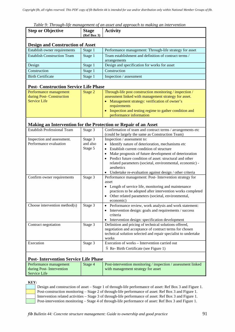
fib Bulletin 44: Concrete structure management: Guide to ownership and good practice 91
Table 9: Through-life management of an asset and approach to making an intervention Step or Objective Stage
(Ref Box 3)Activity
Design and Construction of Asset Establish owner requirements Stage 1 Performance management: Through-life strategy for asset Establish Construction Team Stage 1 Team establishment and definition of contract terms /
arrangements Design Stage 1 Design and specification for works for asset Construction Stage 1 Construction Birth Certificate Stage 1 Inspection / assessment Post- Construction Service Life Phase Performance management during Post- Construction Service Life
Stage 2
Through-life post construction monitoring / inspection / assessment linked with management strategy for asset. • Management strategy: verification of owner’s
requirements • Inspection and testing regime to gather condition and
performance information Making an Intervention for the Protection or Repair of an Asset Establish Professional Team Stage 3 Confirmation of team and contract terms / arrangements etc
(could be largely the same as Construction Team) Inspection and assessment. Performance evaluation
Stage 3 and also Stage 5
Inspection / assessment to: • Identify nature of deterioration, mechanisms etc • Establish current condition of structure • Make prognosis of future development of deterioration • Predict future condition of asset: structural and other
related parameters (societal, environmental, economic) - aesthetics
• Undertake re-evaluation against design / other criteria Confirm owner requirements Stage 3 Performance management: Post- Intervention strategy for
asset • Length of service life, monitoring and maintenance
practices to be adopted after intervention works completed • Other related parameters (societal, environmental,
economic) Choose intervention method(s)
Stage 3 • Performance review, work analysis and work statement: • Intervention design: goals and requirements / success
criteria • Intervention design: specification development
Contract negotiation Stage 3 Definition and pricing of technical solutions offered, negotiation and acceptance of contract terms for chosen technical solution selected and repair specialist to undertake works
Execution Stage 3 Execution of works – Intervention carried out Š Re- Birth Certificate (see Figure 1)
Post- Intervention Service Life Phase Performance management during Post- Intervention Service Life
Stage 4 Post-intervention monitoring / inspection / assessment linked with management strategy for asset
KEY: Design and construction of asset – Stage 1 of through-life performance of asset: Ref Box 3 and Figure 1. Post-construction monitoring – Stage 2 of through-life performance of asset: Ref Box 3 and Figure 1. Intervention related activities – Stage 3 of through-life performance of asset: Ref Box 3 and Figure 1. Post-intervention monitoring – Stage 4 of through-life performance of asset: Ref Box 3 and Figure 1.
Copyright fib, all rights reserved. This PDF copy of fib Bulletin 44 is intended for use and/or distribution only within National Member Groups of fib.
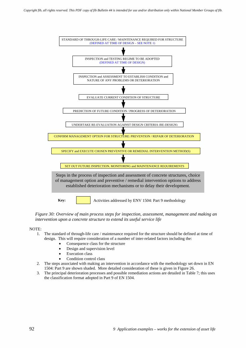
92 9 Application examples – works for the extension of asset life
Figure 30: Overview of main process steps for inspection, assessment, management and making an intervention upon a concrete structure to extend its useful service life
NOTE:
1. The standard of through-life care / maintenance required for the structure should be defined at time of design. This will require consideration of a number of inter-related factors including the:
• Consequence class for the structure • Design and supervision level • Execution class • Condition control class
2. The steps associated with making an intervention in accordance with the methodology set down in EN 1504: Part 9 are shown shaded. More detailed consideration of these is given in Figure 26.
3. The principal deterioration processes and possible remediation actions are detailed in Table 7; this uses the classification format adopted in Part 9 of EN 1504.
INSPECTION and ASSESSMENT TO ESTABLISH CONDITION and NATURE OF ANY PROBLEMS OR DETERIORATION
EVALUATE CURRENT CONDITION OF STRUCTURE
PREDICTION OF FUTURE CONDITION / PROGRESS OF DETERIORATION
CONFIRM MANAGEMENT OPTION FOR STRUCTURE: PREVENTION / REPAIR OF DETERIORATION
SPECIFY and EXECUTE CHOSEN PREVENTIVE OR REMEDIAL INTERVENTION METHOD(S)
SET OUT FUTURE INSPECTION, MONITORING and MAINTENANCE REQUIREMENTS
Steps in the process of inspection and assessment of concrete structures, choice of management option and preventive / remedial intervention options to address
established deterioration mechanisms or to delay their development.
INSPECTION and TESTING REGIME TO BE ADOPTED (DEFINED AT TIME OF DESIGN)
STANDARD OF THROUGH-LIFE CARE / MAINTENANCE REQUIRED FOR STRUCTURE (DEFINED AT TIME OF DESIGN – SEE NOTE 1)
UNDERTAKE RE-EVALUATION AGAINST DESIGN CRITERIA (RE-DESIGN)
Key: Activities addressed by ENV 1504: Part 9 methodology
Copyright fib, all rights reserved. This PDF copy of fib Bulletin 44 is intended for use and/or distribution only within National Member Groups of fib.
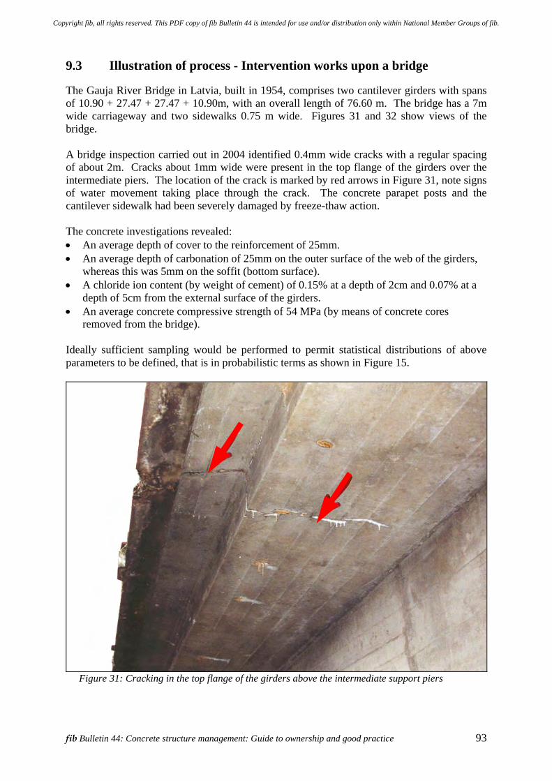
fib Bulletin 44: Concrete structure management: Guide to ownership and good practice 93
9.3 Illustration of process - Intervention works upon a bridge
The Gauja River Bridge in Latvia, built in 1954, comprises two cantilever girders with spans of 10.90 + 27.47 + 27.47 + 10.90m, with an overall length of 76.60 m. The bridge has a 7m wide carriageway and two sidewalks 0.75 m wide. Figures 31 and 32 show views of the bridge. A bridge inspection carried out in 2004 identified 0.4mm wide cracks with a regular spacing of about 2m. Cracks about 1mm wide were present in the top flange of the girders over the intermediate piers. The location of the crack is marked by red arrows in Figure 31, note signs of water movement taking place through the crack. The concrete parapet posts and the cantilever sidewalk had been severely damaged by freeze-thaw action. The concrete investigations revealed: • An average depth of cover to the reinforcement of 25mm. • An average depth of carbonation of 25mm on the outer surface of the web of the girders,
whereas this was 5mm on the soffit (bottom surface). • A chloride ion content (by weight of cement) of 0.15% at a depth of 2cm and 0.07% at a
depth of 5cm from the external surface of the girders. • An average concrete compressive strength of 54 MPa (by means of concrete cores
removed from the bridge). Ideally sufficient sampling would be performed to permit statistical distributions of above parameters to be defined, that is in probabilistic terms as shown in Figure 15.
Figure 31: Cracking in the top flange of the girders above the intermediate support piers
Copyright fib, all rights reserved. This PDF copy of fib Bulletin 44 is intended for use and/or distribution only within National Member Groups of fib.
94 9 Application examples – works for the extension of asset life
The bridge was converted into a continuous girder by the removal of the movement joint over the central pier. This action was taken to overcome a durability weakness and potential problems arising from this type of detail. Fibre reinforced polymer (FRP) strengthening was introduced over the piers and extended out to the 1/3 point of the adjacent spans. FRP strengthening was also added to enhance the shear strength of girders adjacent the piers. This work was necessary to accommodate increased shear forces associated with load redistribution effects created by the change in continuity of the girders. Associated works undertaken included: • Widening the carriageway to 9m. • Undertaking resin injection to seal the cracks in the top flange and the girder walls. • Introduction of membrane on top surface of bridge deck. • Applying a coating to the girders, piers and abutments to provide longer-term protection.
Table 10: Illustration of a simplified process for making an intervention upon a concrete bridge to extend its useful service life
Stage 3 Activities (Refer Table 9)
Observation / Outcome Doc Ref
Inspection and assessment. Performance evaluation Inspection, investigation and assessment to:
The following assumes that the investigation works have been completed.
Box 3 7.3 7.4 fib 17 fib 22
• Identify nature of deterioration, mechanisms etc
• Identify related / other issues
• Carbonation of the concrete • Low cover to reinforcement • Corrosion of reinforcement developing • Cracking in girders over intermediate supports • Water penetration through crack in girder flange • Water penetration at joint over central pier • Deterioration of cantilever footpath structure • Freeze-thaw damage to parapets / posts • Roadway not wide enough for traffic flows
5.2 Ch 7
• Establish current condition of structure
• No impairment of structural capacity • Corrosion initiated on reinforcement in girder sides • Appearance deteriorating
7.4 fib 17 fib 22
• Make prognosis of future development of deterioration
• Concern about future chloride contamination of upper surface (deck) by the use of de-icing salts
• Upper surface (top) reinforcement over intermediate piers at risk of corrosion and deterioration Š potential longer-term reduction in structural capacity of bridge
• To avoid further deterioration / corrosion of main reinforcement it is necessary to stop ingress of chlorides (from de-icing salts) into bridge deck
• Corrosion of reinforcement, loss of steel cross-section and spalling of concrete from sides of beams expected in 15 years
• Water penetration through crack in girder flange expected to lead to local reinforcement corrosion
• Water penetration at joint over central pier expected to cause future durability problems at joint
• Rust stains and spalling will adversely affect aesthetics of bridge.
5.1 5.3 7.4 fib 17 fib 22
Copyright fib, all rights reserved. This PDF copy of fib Bulletin 44 is intended for use and/or distribution only within National Member Groups of fib.
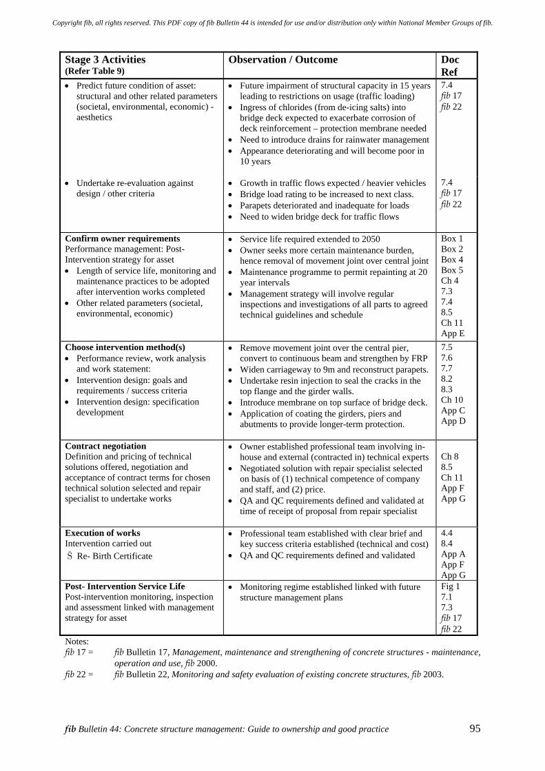
fib Bulletin 44: Concrete structure management: Guide to ownership and good practice 95
Stage 3 Activities (Refer Table 9)
Observation / Outcome Doc Ref
• Predict future condition of asset: structural and other related parameters (societal, environmental, economic) - aesthetics
• Future impairment of structural capacity in 15 years leading to restrictions on usage (traffic loading)
• Ingress of chlorides (from de-icing salts) into bridge deck expected to exacerbate corrosion of deck reinforcement – protection membrane needed
• Need to introduce drains for rainwater management • Appearance deteriorating and will become poor in
10 years
7.4 fib 17 fib 22
• Undertake re-evaluation against design / other criteria
• Growth in traffic flows expected / heavier vehicles • Bridge load rating to be increased to next class. • Parapets deteriorated and inadequate for loads • Need to widen bridge deck for traffic flows
7.4 fib 17 fib 22
Confirm owner requirements Performance management: Post- Intervention strategy for asset • Length of service life, monitoring and
maintenance practices to be adopted after intervention works completed
• Other related parameters (societal, environmental, economic)
• Service life required extended to 2050 • Owner seeks more certain maintenance burden,
hence removal of movement joint over central joint • Maintenance programme to permit repainting at 20
year intervals • Management strategy will involve regular
inspections and investigations of all parts to agreed technical guidelines and schedule
Box 1 Box 2 Box 4 Box 5 Ch 4 7.3 7.4 8.5 Ch 11 App E
Choose intervention method(s) • Performance review, work analysis
and work statement: • Intervention design: goals and
requirements / success criteria • Intervention design: specification
development
• Remove movement joint over the central pier, convert to continuous beam and strengthen by FRP
• Widen carriageway to 9m and reconstruct parapets. • Undertake resin injection to seal the cracks in the
top flange and the girder walls. • Introduce membrane on top surface of bridge deck. • Application of coating the girders, piers and
abutments to provide longer-term protection.
7.5 7.6 7.7 8.2 8.3 Ch 10 App C App D
Contract negotiation Definition and pricing of technical solutions offered, negotiation and acceptance of contract terms for chosen technical solution selected and repair specialist to undertake works
• Owner established professional team involving in-house and external (contracted in) technical experts
• Negotiated solution with repair specialist selected on basis of (1) technical competence of company and staff, and (2) price.
• QA and QC requirements defined and validated at time of receipt of proposal from repair specialist
Ch 8 8.5 Ch 11 App F App G
Execution of works Intervention carried out Š Re- Birth Certificate
• Professional team established with clear brief and key success criteria established (technical and cost)
• QA and QC requirements defined and validated
4.4 8.4 App A App F App G
Post- Intervention Service Life Post-intervention monitoring, inspection and assessment linked with management strategy for asset
• Monitoring regime established linked with future structure management plans
Fig 1 7.1 7.3 fib 17 fib 22
Notes: fib 17 = fib Bulletin 17, Management, maintenance and strengthening of concrete structures - maintenance,
operation and use, fib 2000. fib 22 = fib Bulletin 22, Monitoring and safety evaluation of existing concrete structures, fib 2003.
Copyright fib, all rights reserved. This PDF copy of fib Bulletin 44 is intended for use and/or distribution only within National Member Groups of fib.
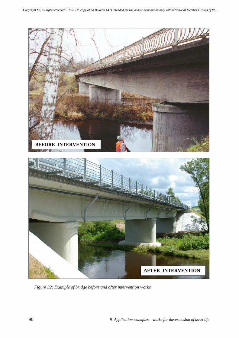
96 9 Application examples – works for the extension of asset life
Figure 32: Example of bridge before and after intervention works
BEFORE INTERVENTION
AFTER INTERVENTION
Copyright fib, all rights reserved. This PDF copy of fib Bulletin 44 is intended for use and/or distribution only within National Member Groups of fib.
fib Bulletin 44: Concrete structure management: Guide to ownership and good practice 97
10 Standards for the protection and repair of concrete structures
The European Standards for concrete repair will have a profound impact on the concrete repair and remediation industry and for owners within Europe, as well as potentially elsewhere within the world. Whilst this is not the only approach or information that exists on this topic (see Appendix D) it is convenient to explore the European approach to illustrate one methodology. For the first time there will be standard requirements for selection of repair techniques and repair products throughout Europe. In the next couple of years industry will be able to specify appropriate repair treatment and product requirements of concrete repair products by CEN standards, and CE marking will be used by manufacturers. The CEN Standard for materials for the protection and repair of concrete is EN 1504, of which there will eventually be ten parts under the general title of; Products and systems for the protection and repair of concrete structures - Definitions, requirements, quality control, and evaluation of conformity. This covers a number of aspects that specifically relate to the design and execution of repair and remediation treatments. The standard will fulfil a number of functions including: • To specify minimum performance levels so that a product can attain approval for sale in
Europe (the CE mark) for a given application. • To remove technical barriers to trade, with a repair product being deemed to satisfy
specification requirements by meeting the defined performance levels, whatever the country of manufacture.
• To provide reference to identification tests, by which a product may be sampled, checked and confirmed to be in accordance with a manufacturer's specification.
• To provide reference to relevant performance tests, by which the designer / specifier can select the most appropriate product for the repair.
• To provide standardised approaches for the design and execution of repairs to concrete structures.
The list of European standards related to the repair and protection of concrete and currently available as standards or are under development by CEN TC104 SC8 are presented in Appendix C. The principles for protection and repair are dealt with in EN 1504-Part 9: 1997 - General principles for the use of products and systems. When confirmed as a full European Standard its use will become effectively mandatory for a wide range of projects. There will therefore be significant advantages for those who gain experience with Part 9 by applying it immediately. For the first time, writers of specifications will have standardised guidance on how to select repair products based on the repair application required. Brief details of standards and guides for the protection and repair of concrete structures adopted in a number of parts of the world are given in Appendix D. These are provided for Europe, Japan, Australia and the USA.
Copyright fib, all rights reserved. This PDF copy of fib Bulletin 44 is intended for use and/or distribution only within National Member Groups of fib.

Copyright fib, all rights reserved. This PDF copy of fib Bulletin 44 is intended for use and/or distribution only within National Member Groups of fib.
fib Bulletin 44: Concrete structure management: Guide to ownership and good practice 99
11 Some frequently asked questions (FAQ) Q1: How do I choose a suitable professional technical team to support me as the owner? A1: Selection should be on the basis of professional technical competence combined with
appropriate previous experience and track record, whilst recognising the ability of different members of the professional team to work together as an integrated team which understands the owner’s objectives and business / service goals. Selection should not be made solely on the basis of fee competition or the lowest initial cost as this does not provide best value in the long run when judged from a through-life perspective. Practically enquiries could be made with other owners who have faced similar problems, asking about their experiences and selecting a team with a good reputation.
Q2: What kind of obligations and responsibilities do I have as an owner? A2: An owner’s legal obligations and responsibilities vary from country to country and
possibly even within a single country, depending on whether there are local statutes and ordinances which apply to particular types of structures or building elements. For example, building owners may have particular responsibilities for inspection of building facades in various cities in order to minimise the risk of falling debris causing injury to members of the public passing by on the street below. Negligence in face of particular duties or more generally could result in criminal prosecution of owners or their staff in some countries if injury or death is caused by their inaction or by taking inappropriate action. Looking more widely, inappropriate action could make an owner liable to financial penalties or expose them to economic sanctions, perhaps by shareholders or other organisations.
Q3: What are the common forms of deterioration of concrete structures? A3: One of the most common problems is corrosion of carbon steel reinforcement
embedded in structural concrete. This is commonly caused when agents such as carbon dioxide from the atmosphere and chlorides, typically originating from the sea when near the coast or from de-icing salts, ingress into the concrete. These processes slowly change the internal chemical conditions within the concrete, which eventually results in the breakdown of the very thin passive oxide layer on the surface of the embedded carbon steel reinforcement that was protecting the steel from corrosion. The stable passive oxide layer is created by the (initially) high pH of the concrete produced during hydration of the cement, which takes place during the setting of the concrete. Generally corrosion will eventually produce a brown staining on parts of the concrete surface, cracking and finally spalling of the concrete surface.
Sulfate in the atmosphere or below ground may attack the minerals forming the
concrete matrix, which is an expansive reaction that can cause disruption and disintegration of the concrete. Alkali-silica reaction is caused by a combination of high humidity in the concrete, high alkali-content in the concrete and high content of an active aggregate. This creates expansion and cracking of the concrete. Freeze-thaw action is caused by freezing and thawing cycles, leading to cracking and potentially to complete physical disruption of the concrete.
These deterioration processes generally develop progressively from the surface of the
concrete and often over a considerable period of time. Also in the case of carbon dioxide and chlorides, these agents eventually produce visible indications through the development of cracks in the concrete as steel reinforcement corrosion progresses to
Copyright fib, all rights reserved. This PDF copy of fib Bulletin 44 is intended for use and/or distribution only within National Member Groups of fib.
100 11 Some frequently asked questions (FAQ)
an advanced stage. In the early stages of these processes (the initiation phase) there are no externally visible indications of the ongoing change in the internal condition of the concrete which eventually results in deterioration and damage.
Q4: What role do inspections and assessments have in managing concrete structures? A4: Inspections and assessments should assist an owner in identifying and managing
health and safety issues, financial risks and maximising the benefits associated with the ownership of an asset. Without inspections and assessment the owner gains no understanding of the real condition or quality of the structure.
A proactive approach to management should enable early identification of problems
and possible risk issues, potentially enabling early preventive action to be taken to minimise the overall cost of ownership. Proactive inspections need to do more than just undertake periodic visual inspections because environmental factors slowly and subtly change the internal conditions within the concrete. As these deterioration processes generally develop progressively from the surface of the concrete, often over considerable periods of time, it is necessary to gather information on the progress of these actions either by inspections or monitoring using an appropriate form of non-destructive testing or sampling of the concrete.
Q5: What problems do cracking and spalling of concrete cause? A5: Cracking and spalling of concrete cause damage to the concrete cover layer,
potentially creating loose pieces of concrete which may pose a hazard of falling debris and the risk of injury to people passing by below. The cracking and spalling is often caused by corrosion of embedded reinforcement. Furthermore cracking, delamination and spalling of cover concrete all increase the potential exposure of the reinforcement to aggressive species such as chlorides and moisture. In turn this will enhance the rate of corrosion and associated damage. In time, if these processes are allowed to continue unchecked, the strength of the structure may be seriously reduced. In some circumstances this change can occur quickly.
Q6: Can the future performance of a repaired concrete structure be estimated
accurately? A6: This is an extremely difficult technical topic because there are a large number of
factors which might influence the future performance of a repaired concrete structure. The factors have varying degrees of influence depending upon circumstances. The factors include the condition of the structure prior to repair, the suitability of the repair or intervention method chosen for the particular circumstances and the effectiveness with which the repair works were carried out (workmanship). Broad indications of a qualitative nature can usually be given about prospective performance and limitations of the remedial procedures to be employed. However it is generally not yet possible to make accurate prognoses about the future performance of a repaired concrete structure because no suitable analytical models have yet been developed.
This said, it is possible to achieve a satisfactory life after repair provided enough
emphasis is placed on undertaking an effective investigation and assessment before making an intervention to either protect or repair the concrete structure, the choice of an appropriate management strategy for the structure and an appropriate intervention, together with adequate quality control of the work carried out (both design and intervention activities).
Copyright fib, all rights reserved. This PDF copy of fib Bulletin 44 is intended for use and/or distribution only within National Member Groups of fib.
fib Bulletin 44: Concrete structure management: Guide to ownership and good practice 101
Q7: How do I select an option for managing a deteriorating concrete structure? A7: Review with the professional team the operational needs and devise a strategy for
managing the asset over the remainder of its expected service life, bearing in mind the economic, social and environmental constraints which may apply. Practically this may require consideration of issues such as functional performance, safety, aesthetics and the degree of certainty in the outcome required by the owner. The process should identify what is important in respect of the business or service needs that the concrete structure was built to address, or has been adapted to fulfil. These should be established as elements of the “core values” of the structure management strategy.
The severity of the deterioration needs to be taken into account, both currently and in
the prognosis of its future impact upon the performance of the structure. Consideration should be given to the changes which might take place over time if the repair or preventive intervention measures are not undertaken, along with the operational and safety implications of such conditions. Account need to be taken of the advantages / disadvantages of the respective options for managing a structure and the contribution they can make to meeting the specified requirements, along with the potential implications of them not doing so. Management of a deteriorating structure may need to utilise techniques such as intensified inspection regimes, monitoring and testing, status indicators and alarms, test loading etc.
Q8: What should I do, I need to make a repair but cannot stop or delay the operations of
the facility or the asset? A8: Clearly this constraint is an important briefing point to communicate to the
professional team. It will be necessary to examine the implications of these overall requirements against the perceived benefits given by various alternatives for protecting or repairing the structure. Advice should be sought as required from the supporting professional team. In reality there may be a number of ways of mitigating the operational difficulties. With bridges, for example, it may be possible to create alternative access routes or adopt alternative working times or arrangements to lessen the difficulties faced by the owner. It may also be possible to adapt the organisation and programming of the intervention works to the owners’ circumstances. This will undoubtedly need proper planning, perhaps also requiring additional or novel preparatory works. For example, take the case where concrete protection and repair works were required to a dry dock structure. The working and access arrangements were organised in a manner so that all plant and equipment could be removed from the dry dock in a very short period. This enabled the dock to be returned to service very quickly should the dry dock secure a commercially valuable project.
Q9: What should be done when seeking to select an appropriate intervention option? A9: An important first step towards selecting a suitable technique for the protection or
repair of a concrete structure is to ensure effective dialogue between the professional team and owner so they all understand what they are seeking to achieve, what the influencing factors and constraints are, plus what the potential “trade-offs” may be. This activity would generally start with the owner briefing the professional team on the performance requirements and operational constraints, along with matters such as permissible disruptions to the functionality of asset and possibly an indication of acceptable cost. Clearly there needs to be owner input (and “buy-in”) to activities which involve not only short- term but also those requiring longer-term engagement, such as a commitment to undertake any future maintenance works which might be
Copyright fib, all rights reserved. This PDF copy of fib Bulletin 44 is intended for use and/or distribution only within National Member Groups of fib.
102 11 Some frequently asked questions (FAQ)
needed to ensure the satisfactory performance of the chosen intervention option. As with all things in life, it is generally an illusion to think that some performance or financial advantage can be gained at no cost or at the expense of some other detriment, such as a shorter life.
An important question which frequently arises is What length of life will I get from
this intervention / repair work? The desired life needs to be defined and agreed in advance as part of the owner briefing, as it influences the choice of intervention technique adopted and the potential cost of the works. The professional team will be able give advice on selection and also an opinion on the potential life for the circumstances involved. However, it should be realised that this is not a precise science and is subject to many uncertainties particularly because of the “trade-offs” which invariably have to be made during the selection process. Workmanship achieved on site can have a large influence on the life achieved, but so will the design and specification of the intervention works.
Q10: What is meant by service life and what importance does this have for the durability
of a repaired concrete structure? A10: ISO 15686: Part 1: 2000 defines service life as the period of time after installation
during which a building or its parts meet or exceed the performance requirements. EN 1504: Part 9: 1997 defines service life more simply as the period in which the intended performance is achieved.
However to establish what is meant by the term service life still requires definition of
the expected performance, so that a judgement can be made as to whether an intervention is performing satisfactorily relative to what was expected of it at the time of its design / selection. There is also a need to define what constitutes failure of an intervention / repair. Importantly these criteria can be defined in the context of both the individual intervention / repair and also the behaviour of the overall structure.
Thus there is a significant difference between the service life of the overall (repaired)
structure and the service life of a particular intervention / repair. The failure of an individual intervention / repair may have little influence on the performance of the overall structure in terms of its safety (reliability index) depending upon the circumstances and context of the particular intervention / repair. Thus consideration of the performance of the overall (repaired) structure will require an understanding an assessment of its global performance, rather than the local behaviour of a particular intervention / repair.
This also leads to a number of the slightly different concepts, such as those of design
service life and expected service life for the structure, which require definition in order to achieve a common understanding. Essentially design service life is a parameter which should be agreed and used when the intervention / repair is being designed / selected. As noted above this parameter can be in terms of the overall (repaired) structure or the individual intervention / repair. Conversely the expected service life is the anticipated out-turn service life based upon monitoring the actual behaviour of the intervention / repair or of the overall structure.
From a practical and perhaps not entirely scientific point of view, the way the term
service life is considered can also be greatly influenced by the owner’s point of view. An owner of a building or facility where deteriorating components are visible to the
Copyright fib, all rights reserved. This PDF copy of fib Bulletin 44 is intended for use and/or distribution only within National Member Groups of fib.
fib Bulletin 44: Concrete structure management: Guide to ownership and good practice 103
public is likely to be much more concerned about its aesthetic appearance than an owner of a structure where the deterioration cannot be seen so easily or widely.
The choice of design service life may greatly influence the choice of intervention /
repair method adopted, the financial aspects (cost) of these works and it will impact upon the further maintenance and inspection regimes required. A relatively short design service life might not be appropriate for a long-life structure (such as a bridge), as it is likely to increase remaining-life costs as short-term intervention works will need to be repeated.
Q11: Can a guarantee be given that this intervention / repair will last 25 years? A11: Very long-term guarantees are not generally available from the industry at this time,
although shorter-term ones of maybe 5 years duration, perhaps extending to 10 years in some instances, can be obtained. This is perhaps because currently a very significant number of repairs exhibit signs of failure within 5 years, and the proportion grows considerably by the time they are 10 – 15 years old. Some of these problems no doubt arise because of owner pressure to minimise first-cost and also because necessary maintenance works are not subsequently undertaken by the owner. However as might be expected this situation varies from structure to structure and amongst owners.
In an industry where most contractors are small, have limited financial resources and
may be at risk of ceasing to trade if difficult circumstances arise, it is often required that guarantees be backed by an insurance company. This gives better security to an owner that the guarantee will be honoured if a valid claim is established against the policy. These guarantees are invariably restricted to the intervention / repair works carried out and are not for the performance of overall repaired structure, unless the complete structure has been treated.
To obtain these guarantees the warrantee provider will typically require the use of
approved materials and methods, a specified contractor and trained (certified) personnel. These stipulations should not be limited only to the workmanship of the repair specialist, but should also extend to the members of the professional team involved with the design and specification of the intervention / repair works. The latter activities are crucial to the effectiveness and longevity of an intervention. Control of these factors seeks to influence the circumstances existing during intervention / repair to improve the chance of success. The use of appropriate QA and QC procedures should also improve the chances of achieving a long-lasting intervention / repair.
As has been noted previously, the choice of intervention / repair option influences its
longevity, as does the management strategy adopted for the structure. Currently the cost of providing a 25 year guarantee would be very high and this would
be passed on directly to the owner by higher prices. A better approach would be to select an appropriate intervention / repair option and to ensure that good quality work was carried out. This is thought to offer a high probability of long-lasting performance at a reasonable remaining-life cost. There are techniques available that should be able to achieve the desired life, such as cathodic protection of corroding reinforcement. It is possible that the most advantageous strategy for managing the
Copyright fib, all rights reserved. This PDF copy of fib Bulletin 44 is intended for use and/or distribution only within National Member Groups of fib.
104 11 Some frequently asked questions (FAQ)
structure and giving lowest remaining-life cost may be to select a method that involves repeated intervention after say every 15 years or so.
Q12: Is life cycle costing a sensible method for comparing different remediation options? A12: Yes because it gives a perspective that better reflects the longer-term issues associated
with the long-term costs of ownership of an asset. However it has to be recognised that the current level of knowledge is still limited and that the approach and methodology is still evolving. Related concepts having a bearing upon these considerations include best value and whole-life value, seeking to broaden the basis upon which decisions are made. These changes are continuing the move away from first-cost (lowest price) which is increasingly seen as inappropriate and as delivering poor overall value to society.
These approaches give consideration to a range of non-technical issues plus other
factors such as service life, residual life of repair options, the influence upon life cycle length, the uncertainty of the performance of alternatives and of the life of repaired structures. However the use of life cycle costing cannot stand alone and be considered in isolation, there are other important requirements to be achieved such as reliability of the safety levels and functional performance attained. Another important proviso, as noted previously (see Figure 6), is the adoption of a sensible discount rate in the calculations as too high a rate erroneously emphasises the importance of short-term considerations and to the disadvantage of more beneficial longer-term options.
Q13: How can the cost of repair works be estimated in advance and what difference can
be expected between an estimate and the out-turn cost? A13: Experienced practitioners suggest that provided an appropriate assessment is made in
advance, the difference between the estimated and the out-turn costs should be a maximum of 15 %. It would therefore seems to make good sense when preparing the total scheme budget to include a provision of at least 15 % of the estimated remedial works total as a contingency sum.
Key aspects of this process are to:
• Undertake a proper diagnosis and investigation, considering the potential impact of changes of scope.
• Undertake a proper quantification survey. • Recognise and take account of level of uncertainty which exists, both of a
technical and financial nature. • Give adequate consideration of access and safety costs, as well as work
limitations due to functional and environmental constraints. • Recognise and take account of the nature of different contractual arrangements
such as fixed price for a closely defined scope of work, or variable price. Consider which could be lowest if managed properly and the potential implications of unknowns.
• Recognise that the choice of intervention / repair technique influences the level of uncertainty and the potential cost of the proposed works.
• Consider what support can be given by an appropriately qualified and experienced professional team during development of the scope of the works.
• Consider the influence that the form of contract may have during the investigative and preparatory phases and upon the execution of the intervention / repair works. An important aspect of this is likely to be the treatment of risk between the parties, whether risk is shared and borne by an appropriate party.
Copyright fib, all rights reserved. This PDF copy of fib Bulletin 44 is intended for use and/or distribution only within National Member Groups of fib.
fib Bulletin 44: Concrete structure management: Guide to ownership and good practice 105
Time-based contracts can result in economies and an agile repair specialist might offer a cheaper overall price than for a fixed price alternative. A target cost contract might offer benefits in relation to assist in the control of any potential overspend if a good initial estimate of the cost of the works can be prepared.
Q14: What should I do to select an appropriate concrete repair specialist? A14: Generally a similar process would be followed to that used for the selection of the
professional technical team to support the owner (see above). As discussed before the basis of selection should be professional technical competence, allied to appropriate previous experience and track record, plus their ability to work in collaboration with this team and the owner. The qualifications / certification of staff should be taken into account, as it is people and the culture that they work within which is a dominant and potentially over-riding influencing factor.
Thus, as before the selection should not be on the basis of lowest first-cost, as this is
unlikely to provide best value in the long run when judged from a through-life perspective.
The selection of the concrete repair specialist might utilise a two-stage approach,
where consideration is initially given to technical competence and the quality of the team and how well the proposed approach meets the stipulated requirements. The provision of a proper methodology with the tender proposal (offering best value) is a critical factor. Price is considered only at the second stage.
Copyright fib, all rights reserved. This PDF copy of fib Bulletin 44 is intended for use and/or distribution only within National Member Groups of fib.

Copyright fib, all rights reserved. This PDF copy of fib Bulletin 44 is intended for use and/or distribution only within National Member Groups of fib.
fib Bulletin 44: Concrete structure management: Guide to ownership and good practice 107
12 Future look and developments 12.1 Overview
If the evolution of societal and sustainability drivers continues the trend seen over recent years, the pressures to extend the useful service life of existing assets can only be expected to become stronger in the future. Overall asset replacement rates are expected to remain low, especially in the “developed world”. In a number of instances for various types of infrastructure these are below 1%. Thus most of the existing assets will have to remain in service and will need to be seen to be safe to do so. Accordingly new ways will need to be found to address these matters and the complexities involved. With the greater realisation which has developed over recent years in relation to matters concerned with the service life design of structures, what further progress can be expected in approaches for the design of new structures to achieve more reliable performance, a better appreciation and prediction of the demands and timing of maintenance works? These developments are bringing a greater focus upon the through-life performance and care of structures, which it is hoped will bring wider benefits and appreciation of the issues associated with keeping existing assets in service. These developments are perhaps epitomised by the recent publication of the fib Model Code for Service Life Design (as fib Bulletin 34). This presents the following four alternative approaches to service life design, namely the: • Full probabilistic method: This will seldom be possible for new structures due to lack of
statistical data, but may be applicable to the assessment of existing structures where appropriate data can be obtained.
• Partial factor method: This approach is based on design values for loads, capacities and geometrical characteristics and is the approach widely used for structural design.
• Deemed-to-satisfy method: This approach involves the application of tabulated values for water-cement ratio, the depth of cover the reinforcing bars, the reinforcement provision to control crack development and crack width etc.
• Avoidance-of-deterioration method: This is also known as the “design-out” approach whereby potential deterioration mechanisms are avoided by removal of one or more components of the potential deterioration mechanism. Thus the problem of deterioration is overcome by actions such as the selective use of stainless steel, the use of non-reactive aggregates, etc
These developments provide a framework within which strategies for the through-life performance and care of structures can be developed. There are also expected to be a mix of technical changes and financial drivers. For example, what are likely to be the implications of the following:
• A greater selective use of stainless steel in construction? • The wider availability and potential (relative) reduction in the price of stainless steels? • The use of lower grade stainless steels (Duplex) in less severe environmental
conditions?
Copyright fib, all rights reserved. This PDF copy of fib Bulletin 44 is intended for use and/or distribution only within National Member Groups of fib.

108 12 Future look and developments
How will such changes impact upon: • the through-life performance and care required for structures? • the relationship between first-cost and whole-life cost in various forms of structure?
Will there be a significant increase the use of stainless steel in construction, and potentially in repairs to existing structures, over time? Technological advances must also be expected to take place in inspection and assessment procedures for existing structures, in the nature of the products and technologies available for the protection and repair of concrete structures, as well as in the amount of information available about the way structures are performing and may be managed. The later is expected to involve considerable improvements in the quantity and coverage of data available to support decision making, enabling much better scenario modelling to take place and to be visualised by those seeking to implement sensible decisions for the management of assets. There will no doubt be changes and developments in legal, social, economic and sustainability drivers influencing the management of assets. However exactly what may arise and how these factors will influence the way owners seek to manage their assets remains to be seen. It seems clear that climate change has the potential to be a major influence upon all these matters. Environmental and other aspects of sustainability (as discussed in earlier sections of the report) seem destined to have considerable influence on owners and the way they seem their obligations to society (through issues such as corporate social responsibility etc). International protocols such as the Kyoto Agreement will impact strongly on many of these matters. Fortunately there are numerous technical developments and ideas for how to move forward. One example is the LIFECON project, funded by the EU and completed December 2003. This developed a generic model of an integrated and predictive Life cycle Maintenance and Management planning System (LMS) that facilitates the change of the facility maintenance and management from a reactive approach into a predictive approach. LIFECON works on life cycle principles and integrates functionality, technical performance, value for money, impact upon the local ecology, safety, health, comfort and culture. LIFECON works by setting up a life cycle action profile (LCAP) for the structure, which results in a decision tree for the management of its repair and maintenance. The decision tree is set up by considering the reliability, availability, maintainability and safety characteristics of each alternative repair technique, as well as its economic and environmental costs. The timing of repair interventions may be forecast using predictive models. The system encourages use of proactive repair strategies. The concepts of performance based building and intervention for the delivery and through-life management of assets are being explored by various workers in a number of countries. These developments are expected to have an influence over time. One example, the application of the performance-based approach to the repair process of concrete structures in the guise of performance-based intervention (PBI) seems feasible. However, the identification of Performance Requirements and Performance Indicators will not be an easy task due the scarcity of precedents and previous experience. Careful consideration will be required of the whole process for making a preventative or remedial intervention in order to make PBI achievable. It appears that new criteria, along with methods to measure performance relating to these criteria, will need to be introduced.
Copyright fib, all rights reserved. This PDF copy of fib Bulletin 44 is intended for use and/or distribution only within National Member Groups of fib.
fib Bulletin 44: Concrete structure management: Guide to ownership and good practice 109
To facilitate the adoption of the PBI it will be necessary to develop models which provide a basis for evaluating the effects of ageing upon both repairs and the repaired structure. Such models would need to allow estimates to be made of the remaining service life of the repaired structure and facilitate management of existing structures in the post-intervention phase of their life. The concepts associated with PBI have been explored within the CONREPNET project; along with a vision for PBI, a methodology for implementing the approach and future actions necessary to support the further development and use of PBI. However, in the short-term a valuable achievement would simply be greater recognition amongst owners of the important influence that durability has upon:
• the through-life performance of a structure, and • the associated whole-life cost of ownership.
As durability is generally a property of the cover concrete, it is this part of a reinforced concrete structure which can be most vulnerable to poor quality; especially when the structure is situated within an aggressive environment. There is concern amongst some experienced engineers and construction personnel that quality management procedures employed during the design and construction of concrete structures have not always achieve satisfactory product quality and hence durability. Problems encountered during the construction phase often have their roots within earlier stages of the project; such as when the design, detailing or material specification tasks are carried out. Special efforts, primarily in the form of pre-planning construction activities and verification of the processes adopted during execution, can help overcome these potential difficulties. The adoption of a risk based approach / methodology to quality management potentially provides a way forward and is being adopted by major contractors to supplement the basic requirements of the ISO 9001 system. In complex situations and projects the adoption of a systems engineering approach might be useful as this would potentially provide an effective way of managing the interfaces between the various actors involved and between different packages of work. These activities could bring benefits in terms of improved durability and lower whole-life cost of ownership. Many owners need to take a longer-term whole-life perspective to get best value for money and to minimise overall environmental impacts. A focus upon first-cost may lead to decisions that apparently save money, but subsequently prove to be a false economy. This can be particularly so for longer-life structures.
12.2 Potential implications of climate change
In future years an issue that is likely to become increasing significant for the management of existing buildings and infrastructure assets is climate change, with the potential implications this may have for environmental loadings and the in-service performance of structures. Owners will need to take into account the possible effects of climate change, in addition to the existing range of factors they currently consider. Although there is some degree of consensus in the scientific community that there are measurable changes in the world’s environment, such as the rising concentration of
Copyright fib, all rights reserved. This PDF copy of fib Bulletin 44 is intended for use and/or distribution only within National Member Groups of fib.

110 12 Future look and developments
greenhouse gases (mainly carbon dioxide) in the atmosphere; the implications of these apparent changes seem to be far less certain with a wide range of possible scenarios being discussed. These include higher atmospheric temperatures, more frequent storms, a significant increase in sea level, a greater incidence and increase in the severity of driving rain, flooding, erosion, etc. The higher atmospheric temperature is expected to increase the overall intensity of storms. Some parts of the world are anticipated to experience greater rainfall, leading to an increase in the level of the ground water table, and more storms; whereas it is anticipated that other parts may become significantly drier. The construction industry and the owners of structures should not ignore the possible consequences of climate change as they may be profound in nature and wide reaching.
Copyright fib, all rights reserved. This PDF copy of fib Bulletin 44 is intended for use and/or distribution only within National Member Groups of fib.
fib Bulletin 44: Concrete structure management: Guide to ownership and good practice 111
13 References, websites and further reading These items are classified under the following headings:
• General • Assessment, inspection, monitoring and repair of concrete structures • Client requirements and value from construction • Deterioration, protection and repair of concrete structures • Durability, service life design and through-life performance • Environmental issues • Health and safety issues • Product standards related to concrete structures • Quality issues • Risk assessment and risk management • Structural design of concrete structures • Whole life costing and value
NOTE: Website addresses were valid at the time of publication of this guide. General A report card on the nation’s infrastructure: Investigating the health of Australia’s water systems, roads, railways and bridges. Institution of Engineers, Australia, 1999. Hertle R, Ursachen und Folgen des Einsturzes der Dachkonstruktion der Eissporthalle in Bad Reichenhal" (Reasons for and consequences of the failure of the roof construction of the ice pavilion in Bad Reichenhall), Der Prüfingenieur, volume 29, October 2006, p16 to 20. Kernohan D, Gray J and Daish J, User participation in building design and management, 2nd Edition, Butterworth Architecture, London, UK, 1996. The state of the nation 2004 – Measuring the quality of the UK’s infrastructure, New Civil Engineer, June 2004 The state of the nation 2006 – Measuring the quality of the UK’s infrastructure, New Civil Engineer, October 2006 Turnbull N et al, Internal control: Guidance for directors on the combined code. Institute of Chartered Accountants in England and Wales, September 1999. Assessment, inspection, monitoring and repair of concrete structures ACI Committee 440, Fibre reinforced polymer reinforcement, located at website http://www.concrete.org/COMMITTEES/committeehome.asp?committee_code=0000440-00. ACI 546R-96 Concrete repair guide, American Concrete Institute ACRA/CSIRO Guide to concrete repair and protection Assessment of existing structures, Institution of Structural Engineers, London – Currently being revised as 3rd Edition, 2008.
Copyright fib, all rights reserved. This PDF copy of fib Bulletin 44 is intended for use and/or distribution only within National Member Groups of fib.
112 13 References, websites and further reading
CONREPNET Project : Achieving durable repaired concrete structures: Adopting a performance-based intervention strategy, Edited by Matthews SL et al, CONREPNET Project report, IHS BRE Press, Watford, UK, November 2007, Ref. EP77, ISBN 978-1-86081-970-4, 190pp.
CONTECVET - A validated users manual for assessing the residual service life of concrete structures, EC Innovation Programme, Contract IN30902I. The documents are located at website http://olivier.calma.free.fr/HW/2d_term/InspectAssessRepair/CONTECVET
Manual for assessing concrete structures affected by frost, prepared by the Swedish partners: Vattenfall Utveckling AB, Banverket, Swedish National Road Administration, Lund Institute of Technology and Skanska Teknik AB.
Manual for assessing concrete structures affected by ASR, prepared by: British Cement Association.
Manual for assessing corrosion-affected concrete structures, prepared by: Geocisa and IETcc
fib Bulletin 17, Management, maintenance and strengthening of concrete structures - maintenance, operation and use, fib 2002. fib Bulletin 22, Monitoring and safety evaluation of existing concrete structures, fib 2003. ISO 13822, Bases for design of structures – Assessment of existing structures, ISO, 2001. NCHRP Report 514, Bonded repaired and retrofit on concrete structures using FRP composites, Transportation Research Board, 2004. Recommendations for the inspection, maintenance and management of car park structures, Institution of Civil Engineers, London, 2002. The following web site hosted by Texas DOT, http://www.dot.state.tx.us/services/general_services/manuals.htm gives information on:
• USA Federally mandated NBI (safety) inspections for bridges - which are intended to be performed every two years, and
• routine maintenance inspections to be performed every 6 months by maintenance personnel
Client requirements and value from construction Hayles C S, Bowles G and Gronqvist M, Value from construction: A comprehensive bibliography, BRE Report 333, IHS BRE Press, Watford, UK, Oct 1997, ISBN 1860811760, 38pp. Hayles C and Simister S, Value from construction, BRE Report 396, IHS BRE Press, Watford, UK, June 2000, ISBN 1860814018, 12pp. Hayles C and Simister S, The value workshop, BRE Report 397, IHS BRE Press, Watford, UK, June 2000, ISBN 1860814026, 12pp.
Copyright fib, all rights reserved. This PDF copy of fib Bulletin 44 is intended for use and/or distribution only within National Member Groups of fib.
fib Bulletin 44: Concrete structure management: Guide to ownership and good practice 113
Hayles C and Simister S, Value for social housing, BRE Report 398, IHS BRE Press, Watford, UK, June 2000, ISBN 1860814034, 12pp. Hayles C and Simister S, The FAST approach - function analysis and diagramming techniques, BRE Report BR 399, IHS BRE Press, Watford, UK, 2000. Hill R M, Better building – Integrating the supply chain: A guide for clients and their consultants, BRE Digest 450, IHS BRE Press, Watford, UK, Aug 2000, ISBN 1860814239, 12pp. Prior J J and Rizzi F, Getting it right: a clients' guide to functionality, BRE Report 452, IHS BRE Press, Watford, UK, July 2003, ISBN 1860816061, 42pp. Deterioration, protection and repair of concrete structures Bahrain Society of Engineers, Deterioration and repair of reinforced concrete in the Arabian Gulf; Proceedings of a series of international conferences held in Bahrain and variously sponsored by the Bahrain Society of Engineers, The Concrete Society, American Concrete Institute and CIRIA; published by the Bahrain Society of Engineers. These include:
• Proceedings of the 6th international conference, 20-22 November 2000. • Proceedings of the 5th international conference, 27-29 October 1997. • Proceedings of the 3rd international conference, 21-24 October 1989. • Proceedings of the 2nd international conference, 11-13 October 1987.
Concrete repair manual 2nd Edition, International Concrete Repair Institute, principal editors P Emmons and S L Matthews, 2003. CIRIA Technical Report C577, Guide to the construction of reinforced concrete in the Arabian Peninsula, CIRIA and The Concrete Society, London, 2002, ISBN 978-0-946691-93-7, 208pp. EN 1504: Products and systems for the protection and repair of concrete structures - Definitions, requirements, quality control, evaluation of conformity. In ten parts (1 to 10) but of particularly relevance is Part 9: General principles for the use of products and systems, CEN (publication dates vary).
REHABCON - Strategy for maintenance and rehabilitation in concrete structures, Innovation and SME Programme - Contract IPS-2000-0063.
REHABCON Manual - Strategy for maintenance and rehabilitation in concrete structures, REHABCON final project deliverables comprising the Main report and Annexes. Available from CBI (www.cbi.se).
Durability, service life design and through-life performance Bamforth P, Enhancing reinforced concrete durability; guidance on selecting measures for minimising the risk of corrosion of reinforcement in concrete, Concrete Society Technical Report 61, The Concrete Society, Camberley, UK, 2004. Concrete Society Technical Report 51, Guidance on the use of stainless steel reinforcement, The Concrete Society, Camberley, UK, 1998.
Copyright fib, all rights reserved. This PDF copy of fib Bulletin 44 is intended for use and/or distribution only within National Member Groups of fib.
114 13 References, websites and further reading
Driscoll, S., Sirivivatnanon, V. and Khatri, R.P., Performance of a 25-year-old coastal concrete wharf structure, Proceedings of the AUSTROADS 1997 Bridge Conference, Sydney, Australia, December 1997. fib Bulletin 34, Model code for service life design of concrete structures, fib 2006. ISO/DIS 13823: General principles on the design of structures for durability, ISO, 2006 ISO 15686-1:2000, Buildings and constructed assets - Service life planning, Part 1: General principles, ISO, 2000. ISO 15686-2:2001, Buildings and constructed assets - Service life planning, Part 2: Service life prediction procedures, ISO, 2001. ISO 15686-3:2002, Buildings and constructed assets - Service life planning, Part 3: Performance audits and reviews, ISO, 2002. ISO 15686-5:2007, Buildings and constructed assets - Service life planning, Part 5: Life-cycle costing, ISO, 2007. ISO 15686-6:2004, Buildings and constructed assets - Service life planning, Part 6: Procedures for considering environmental impacts, ISO, 2004. ISO 15686-7:2006, Buildings and constructed assets - Service life planning - Part 7: Performance evaluation for feedback of service life data from practice, ISO, 2006. ISO/DIS 22966, Execution of concrete structures, ISO, 2008. Khatri, R.P., Guirguis, S. and Sirivivatnanon, V., 60 years service life of Port Kembla concrete swimming pool, Proceedings of Concrete 2001, Concrete Institute of Australia Biennial Conference. 11-14 September, 2001, Perth, Australia. pp. 55-62.
LIFECON - Life cycle management of concrete infrastructures for improved sustainability, competitive and sustainable, Competitive and Sustainable Growth Programme – Contract G1RD-CT-2000-00378. The project deliverables are located at website www.vtt.fi//rte/strat/projects/lifecon/summary.htm.
Söderqvist MK. and Vesikari E., Generic technical handbook for a predictive life cycle management system of concrete structures, LIFECON Project Deliverable D1.1.
Vesikari E., Statistical condition management and financial optimisation in lifetime management of structures. LIFECON Project Deliverable D2.2.
Lair J., Rissanen T. and Sarja A., Methods for optimisation and decision making in lifetime management of structures. LIFECON Project Deliverable D2.3.
Miller J.B. and I.B. and Sarkkinen M., Qualitative and quantitative description and classification of RAMS (reliability, availability, maintainability and safety) characteristics for different categories of repair materials and systems. LIFECON Project Deliverable D5.1.
Copyright fib, all rights reserved. This PDF copy of fib Bulletin 44 is intended for use and/or distribution only within National Member Groups of fib.
fib Bulletin 44: Concrete structure management: Guide to ownership and good practice 115
Nolan É, Quillin K, Somerville G, Nixon P and Sergi G, Reinforced concrete service life design. Part 1. Overview, BRE Information Paper IP3/06, IHS BRE Press, Watford, UK, May 2006. Nolan É, Quillin K and Somerville G, Reinforced concrete service life design. Part 2. Design for durability, BRE Information Paper IP3/06, IHS BRE Press, Watford, UK, May 2006. Nolan É, Quillin K, Nixon P, Sergi G and Bamforth PB, Reinforced concrete service life design. Part 3. Service life forecasting and enhancement, BRE Information Paper IP3/06, IHS BRE Press, Watford, UK, May 2006, ISBN 1860819087, 8pp. Quillin K, Modelling degradation processes affecting concrete, BRE Report 434, IHS BRE Press, Watford, UK, 2001. Quillin K, Somerville G, Hooper R and Nixon P, A framework for service life design of concrete structures, 9th International Conference on Durability of Building Materials and Components, Brisbane Convention and Exhibition Centre, Australia, 17–21 March 2002. Tuutti K, Corrosion of steel in concrete, Swedish Cement and Concrete Research Institute, Stockholm, Report No. CBI Research FO 4:82, 1982 Environmental issues Dickie I and Howard N, Assessing environmental impacts of construction: Industry consensus, BREEAM and UK Ecopoints, BRE Digest 446, IHS BRE Press, Watford, UK, 2000. EN ISO 14040, Environmental Management, Life cycle assessment. Principles and framework, ISO, 1998. fib Bulletin 21, Environmental issues in prefabrication, fib 2003. Steele K, A methodology to facilitate the environmental comparison of bridge management strategies, Ph.D Thesis, University of Surrey, Guildford, UK, Sept. 2003. Health and safety issues European Workplace Directive / legislation on responsibilities during the lifespan of buildings and structures. NB. Also UK HSE legislation upon “stability and solidity” – Workplace regulations 1992 (as amended). European Organisation for Technical Approvals, www.eota.be. Winsperger, Hintermeier, Inclusion of national regulations concerning dangerous substances within the framework of the CPD, Institute for Industrial Ecology in Austria, Reiss Austrian Ministry for Environment: from the CEN/STAR PNR workshop, CSTB, Paris, June 2000. European Union legislation concerning workers safety and health: Community legislation laying down minimum requirements for the protection of workers contained in Directive 89/391/EEC and individual directives based thereon, in particular Directive 90/394/EEC.
Copyright fib, all rights reserved. This PDF copy of fib Bulletin 44 is intended for use and/or distribution only within National Member Groups of fib.
116 13 References, websites and further reading
Council Directive 89/391/EEC of 12 June 1989 on the introduction of measures to encourage improvements in the safety and health of workers at work Council Directive 90/394/EEC of 28 June 1990 on the protection of workers from the risks related to exposure to carcinogens at work (including amendments 97/42/EC and 99/38/EC). Council Directive 98/24/EC of 7 April 1998 on the protection of the health and safety of workers from the risks related to chemical agents at work (fourteenth individual Directive within the meaning of Article 16(1) of Directive 89/391/EEC) Council Directive 83/477/EEC of 19 September 1983 on the protection of workers from the risks related to exposure to asbestos at work (second individual Directive within the meaning of Article 8 of Directive 80/1107/EEC) Source: http://europa.eu.int/comm/enterprise/construction/internal/dangsub/explcoueu.htm EC Guidance paper H from: http://europa.eu.int/comm/enterprise/construction/internal/guidpap/h.htm Product standards related to concrete structures EN 206-1: 2000: Concrete: Part 1: Specification, performance, production and conformity, CEN 2000. prEN 13670: 2006: Execution of concrete structures, CEN 2006. Quality issues Curtis S., Design for durability by bridging the gap between designers intent and construction contract practice, Proc. Fifth International Conference on Durability of Concrete, Barcelona, Spain. Supplementary Papers, pp. 823-837, 2000. Curtis S., The effective application of quality assurance principles for producing durable concrete structures: the problems and the solutions, Proceedings of fib Congress, Osaka, Japan, 2002. Gimsing N, Concrete technology, The Storebaelt Publications, 271pp, 1999. ISO 9001: Quality management systems - Requirements, ISO, 2000. Risk assessment and risk management Faber M.H, Risk and safety in civil engineering, Lecture Notes. ETHZ, Zurich, Switzerland, 2001 Risk assessment and risk communication in civil engineering, CIB Publication 259, a report from CIB WG32, Edited by Vrouwenvelder A, Holicky BM, Tanner CP, Lovegrove DR and Canisius TDG, ISBN 90- 6363-026-3, available from CIB General Secretariat, Rotterdam. The Royal Academy of Engineering – RAE. The societal aspects of risk, RAE, London, U.K. Available from website http://www.raeng.org.uk/news/publications/list/reports/The_Societal_ Aspects_of_Risk.pdf
Copyright fib, all rights reserved. This PDF copy of fib Bulletin 44 is intended for use and/or distribution only within National Member Groups of fib.
fib Bulletin 44: Concrete structure management: Guide to ownership and good practice 117
Tjallingii S, Ecological conditions - strategies and structures in environmental planning. IBN Scientific Contributions 2. DLO Institute for Forestry and Nature Research, Wageningen, 1996. Vrouwenwelder A., Holicky M, Tanner P, Lovegrove R and Canisius T.D.G., Risk assessment and risk communication in civil engineering, CIB Report 259, ISBN 90- 6363-026-3, February 2001. Structural design of concrete structures Eurocode EN 1990: Basis of structural design, CEN. Eurocode EN 1991: Actions on structures, CEN. Eurocode EN 1992-Part 1.1: General rules and rules for buildings. CEN. Eurocode EN 1992-Part 1-2: Structural fire design, CEN. Eurocode EN 1992-Part 2: Bridges, CEN. Eurocode EN 1992-Part 3: Liquid retaining and containment structures, CEN. ISO 2394: General principles on reliability for structures, ISO, 1998. SCOSS 14th Biennial Report, Structural safety 2001 – 2003: Review and recommendations, Standing Committee on Structural Safety, London, UK, 2003, via www.scoss.org.uk Whole life costing and value Bourke K, Ramdas V, Singh S, Green A, Crudgington A and Mootanah D, Achieving whole life value in infrastructure and buildings, BRE Report 476, IHS BRE Press, Watford, UK, Feb 2005, ISBN 1860817378, 60pp Clift M and Bourke K, Study on whole life costing, BRE Report 367, IHS BRE Press, Watford, UK, May 1999, ISBN 1860812805, 29pp. De Sitter W.R., Costs for service life optimization: the “law of fives”, Durability of Concrete Structures, Workshop Report, Ed. Rostam, Copenhagen, Denmark, pp. 131-134, 18-20 May 1984. Edwards S, Bartlett E and Dickie I, Whole life costing and life-cycle assessment for sustainable building design, BRE Digest 452, IHS BRE Press, Watford, UK, Nov 2000, ISBN 1860814417, 8pp. The Royal Academy of Engineering – RAE. The long term costs of owning and using buildings, RAE, London, U.K, 1998. Available from website http://www.raeng.org.uk/ news/publications/list/reports/The_Long-Term_Costs_of_Buildings.pdf
Copyright fib, all rights reserved. This PDF copy of fib Bulletin 44 is intended for use and/or distribution only within National Member Groups of fib.

Copyright fib, all rights reserved. This PDF copy of fib Bulletin 44 is intended for use and/or distribution only within National Member Groups of fib.
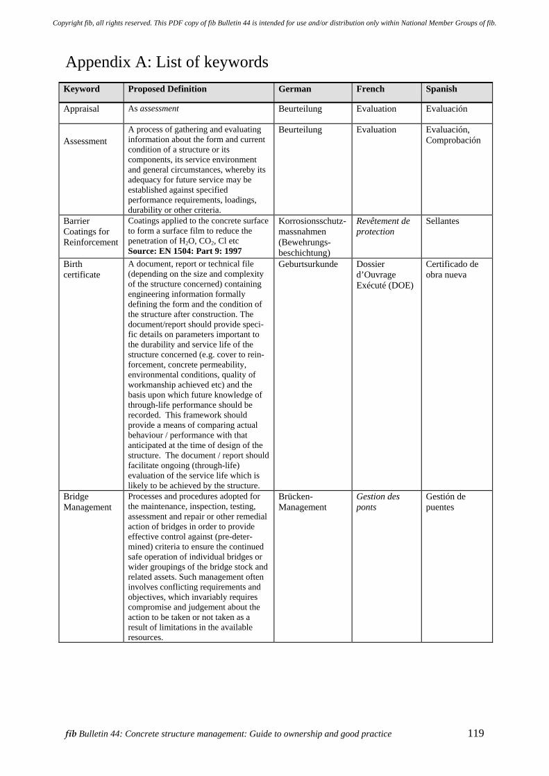
fib Bulletin 44: Concrete structure management: Guide to ownership and good practice 119
Appendix A: List of keywords Keyword Proposed Definition German French Spanish
Appraisal As assessment
Beurteilung Evaluation Evaluación
Assessment A process of gathering and evaluating information about the form and current condition of a structure or its components, its service environment and general circumstances, whereby its adequacy for future service may be established against specified performance requirements, loadings, durability or other criteria.
Beurteilung Evaluation Evaluación, Comprobación
Barrier Coatings for Reinforcement
Coatings applied to the concrete surface to form a surface film to reduce the penetration of H2O, CO2, Cl etc Source: EN 1504: Part 9: 1997
Korrosionsschutz-massnahmen (Bewehrungs-beschichtung)
Revêtement de protection
Sellantes
Birth certificate
A document, report or technical file (depending on the size and complexity of the structure concerned) containing engineering information formally defining the form and the condition of the structure after construction. The document/report should provide speci-fic details on parameters important to the durability and service life of the structure concerned (e.g. cover to rein-forcement, concrete permeability, environmental conditions, quality of workmanship achieved etc) and the basis upon which future knowledge of through-life performance should be recorded. This framework should provide a means of comparing actual behaviour / performance with that anticipated at the time of design of the structure. The document / report should facilitate ongoing (through-life) evaluation of the service life which is likely to be achieved by the structure.
Geburtsurkunde Dossier d’Ouvrage Exécuté (DOE)
Certificado de obra nueva
Bridge Management
Processes and procedures adopted for the maintenance, inspection, testing, assessment and repair or other remedial action of bridges in order to provide effective control against (pre-deter-mined) criteria to ensure the continued safe operation of individual bridges or wider groupings of the bridge stock and related assets. Such management often involves conflicting requirements and objectives, which invariably requires compromise and judgement about the action to be taken or not taken as a result of limitations in the available resources.
Brücken-Management
Gestion des ponts
Gestión de puentes
Copyright fib, all rights reserved. This PDF copy of fib Bulletin 44 is intended for use and/or distribution only within National Member Groups of fib.
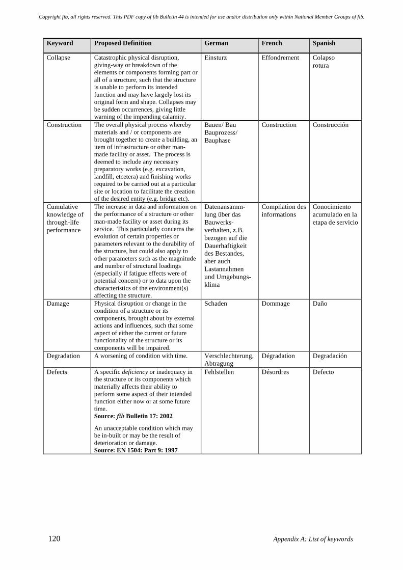
120 Appendix A: List of keywords
Keyword Proposed Definition German French Spanish
Collapse Catastrophic physical disruption, giving-way or breakdown of the elements or components forming part or all of a structure, such that the structure is unable to perform its intended function and may have largely lost its original form and shape. Collapses may be sudden occurrences, giving little warning of the impending calamity.
Einsturz Effondrement Colapso rotura
Construction The overall physical process whereby materials and / or components are brought together to create a building, an item of infrastructure or other man-made facility or asset. The process is deemed to include any necessary preparatory works (e.g. excavation, landfill, etcetera) and finishing works required to be carried out at a particular site or location to facilitate the creation of the desired entity (e.g. bridge etc).
Bauen/ Bau Bauprozess/ Bauphase
Construction Construcción
Cumulative knowledge of through-life performance
The increase in data and information on the performance of a structure or other man-made facility or asset during its service. This particularly concerns the evolution of certain properties or parameters relevant to the durability of the structure, but could also apply to other parameters such as the magnitude and number of structural loadings (especially if fatigue effects were of potential concern) or to data upon the characteristics of the environment(s) affecting the structure.
Datenansamm-lung über das Bauwerks-verhalten, z.B. bezogen auf die Dauerhaftigkeit des Bestandes, aber auch Lastannahmen und Umgebungs-klima
Compilation des informations
Conocimiento acumulado en la etapa de servicio
Damage Physical disruption or change in the condition of a structure or its components, brought about by external actions and influences, such that some aspect of either the current or future functionality of the structure or its components will be impaired.
Schaden Dommage Daño
Degradation A worsening of condition with time. Verschlechterung, Abtragung
Dégradation Degradación
Defects A specific deficiency or inadequacy in the structure or its components which materially affects their ability to perform some aspect of their intended function either now or at some future time. Source: fib Bulletin 17: 2002
An unacceptable condition which may be in-built or may be the result of deterioration or damage. Source: EN 1504: Part 9: 1997
Fehlstellen Désordres Defecto
Copyright fib, all rights reserved. This PDF copy of fib Bulletin 44 is intended for use and/or distribution only within National Member Groups of fib.
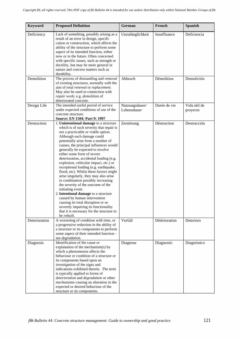
fib Bulletin 44: Concrete structure management: Guide to ownership and good practice 121
Keyword Proposed Definition German French Spanish
Deficiency Lack of something, possibly arising as a result of an error in design, specifi-cation or construction, which affects the ability of the structure to perform some aspect of its intended function, either now or in the future. Often concerned with specific issues, such as strength or ductility, but may be more general in nature and concern matters such as durability.
Unzulänglichkeit Insuffisance Deficiencia
Demolition The process of dismantling and removal of existing structures, normally with the aim of total renewal or replacement. May also be used in connection with repair work; e.g. demolition of deteriorated concrete.
Abbruch Démolition Demolición
Design Life The intended useful period of service under expected conditions of use of the concrete structure. Source: EN 1504: Part 9: 1997
Nutzungsdauer/ Lebensdauer
Durée de vie Vida útil de proyecto
Destruction 1. Unintentional damage to a structure which is of such severity that repair is not a practicable or viable option. Although such damage could potentially arise from a number of causes, the principal influences would generally be expected to involve either some form of severe deterioration, accidental loading (e.g. explosion, vehicular impact, etc.) or exceptional loading (e.g. earthquake, flood, etc). Whilst these factors might arise singularly, they may also arise in combination possibly increasing the severity of the outcome of the initiating event.
2. Intentional damage to a structure caused by human intervention causing its total disruption or so severely impairing its functionality that it is necessary for the structure to be rebuilt.
Zerstörung Déstruction Destrucción
Deterioration A worsening of condition with time, or a progressive reduction in the ability of a structure or its components to perform some aspect of their intended function - see degradation.
Verfall Détérioration Deterioro
Diagnosis Identification of the cause or explanation of the mechanism(s) by which a phenomenon affects the behaviour or condition of a structure or its components based upon an investigation of the signs and indications exhibited therein. The term is typically applied to forms of deterioration and degradation or other mechanisms causing an alteration in the expected or desired behaviour of the structure or its components.
Diagnose Diagnostic Diagnóstico
Copyright fib, all rights reserved. This PDF copy of fib Bulletin 44 is intended for use and/or distribution only within National Member Groups of fib.
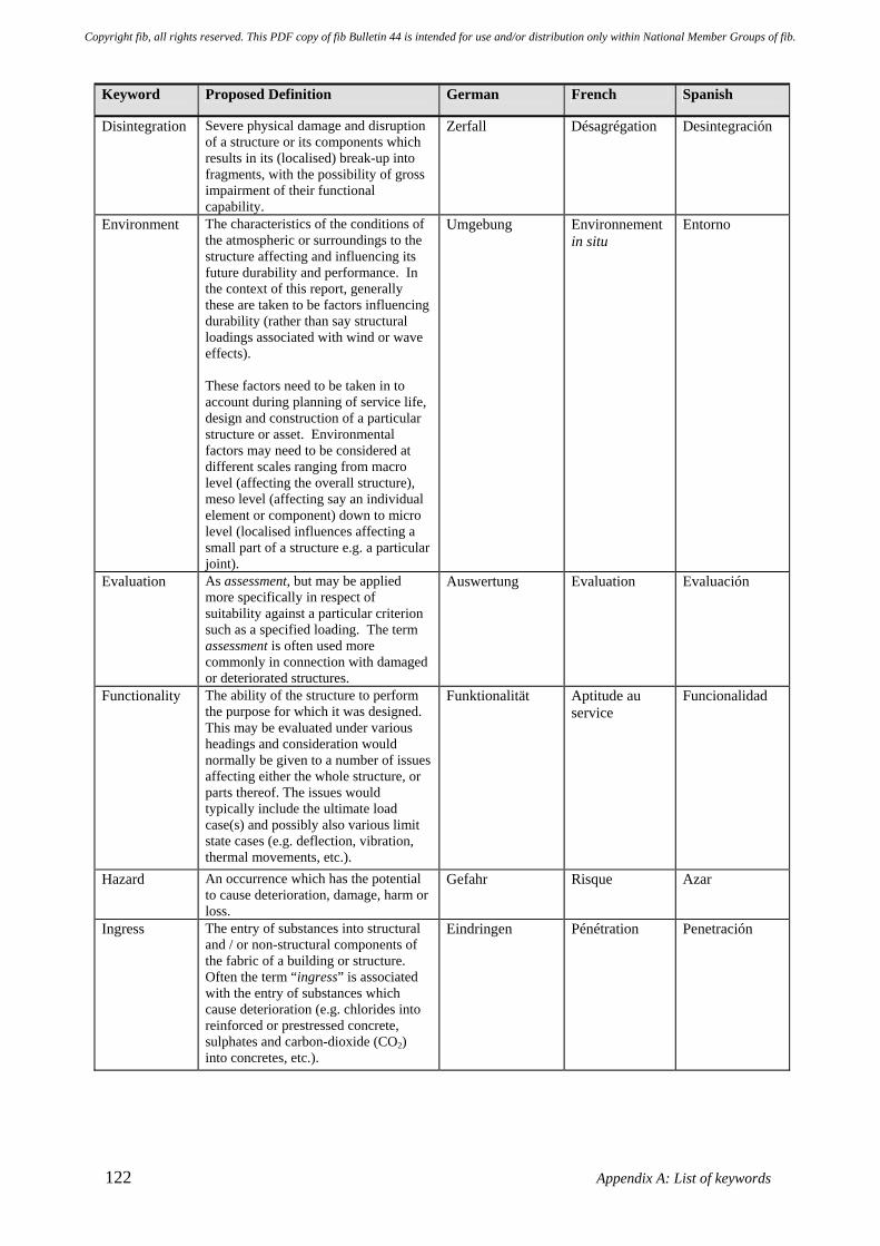
122 Appendix A: List of keywords
Keyword Proposed Definition German French Spanish
Disintegration Severe physical damage and disruption of a structure or its components which results in its (localised) break-up into fragments, with the possibility of gross impairment of their functional capability.
Zerfall Désagrégation Desintegración
Environment The characteristics of the conditions of the atmospheric or surroundings to the structure affecting and influencing its future durability and performance. In the context of this report, generally these are taken to be factors influencing durability (rather than say structural loadings associated with wind or wave effects). These factors need to be taken in to account during planning of service life, design and construction of a particular structure or asset. Environmental factors may need to be considered at different scales ranging from macro level (affecting the overall structure), meso level (affecting say an individual element or component) down to micro level (localised influences affecting a small part of a structure e.g. a particular joint).
Umgebung Environnement in situ
Entorno
Evaluation As assessment, but may be applied more specifically in respect of suitability against a particular criterion such as a specified loading. The term assessment is often used more commonly in connection with damaged or deteriorated structures.
Auswertung Evaluation Evaluación
Functionality The ability of the structure to perform the purpose for which it was designed. This may be evaluated under various headings and consideration would normally be given to a number of issues affecting either the whole structure, or parts thereof. The issues would typically include the ultimate load case(s) and possibly also various limit state cases (e.g. deflection, vibration, thermal movements, etc.).
Funktionalität Aptitude au service
Funcionalidad
Hazard An occurrence which has the potential to cause deterioration, damage, harm or loss.
Gefahr Risque Azar
Ingress The entry of substances into structural and / or non-structural components of the fabric of a building or structure. Often the term “ingress” is associated with the entry of substances which cause deterioration (e.g. chlorides into reinforced or prestressed concrete, sulphates and carbon-dioxide (CO2) into concretes, etc.).
Eindringen Pénétration Penetración
Copyright fib, all rights reserved. This PDF copy of fib Bulletin 44 is intended for use and/or distribution only within National Member Groups of fib.
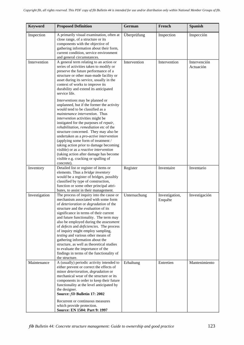
fib Bulletin 44: Concrete structure management: Guide to ownership and good practice 123
Keyword Proposed Definition German French Spanish
Inspection A primarily visual examination, often at close range, of a structure or its components with the objective of gathering information about their form, current condition, service environment and general circumstances.
Überprüfung Inspection Inspección
Intervention A general term relating to an action or series of activities taken to modify or preserve the future performance of a structure or other man-made facility or asset during its service, usually in the context of works to improve its durability and extend its anticipated service life.
Interventions may be planned or unplanned, but if the former the activity would tend to be classified as a maintenance intervention. Thus intervention activities might be instigated for the purposes of repair, rehabilitation, remediation etc of the structure concerned. They may also be undertaken as a pro-active intervention (applying some form of treatment / taking action prior to damage becoming visible) or as a reactive intervention (taking action after damage has become visible e.g. cracking or spalling of concrete).
Intervention Intervention Intervención Actuación
Inventory Detailed list or register of items or elements. Thus a bridge inventory would be a register of bridges, possibly classified by type of construction, function or some other principal attri-butes, to assist in their management.
Register Inventaire Inventario
Investigation The process of inquiry into the cause or mechanism associated with some form of deterioration or degradation of the structure and the evaluation of its significance in terms of their current and future functionality. The term may also be employed during the assessment of defects and deficiencies. The process of inquiry might employ sampling, testing and various other means of gathering information about the structure, as well as theoretical studies to evaluate the importance of the findings in terms of the functionality of the structure.
Untersuchung Investigation, Enquête
Investigación
Maintenance A (usually) periodic activity intended to either prevent or correct the effects of minor deterioration, degradation or mechanical wear of the structure or its components in order to keep their future functionality at the level anticipated by the designer. Source: fib Bulletin 17: 2002
Recurrent or continuous measures which provide protection. Source: EN 1504: Part 9: 1997
Erhaltung Entretien Mantenimiento
Copyright fib, all rights reserved. This PDF copy of fib Bulletin 44 is intended for use and/or distribution only within National Member Groups of fib.
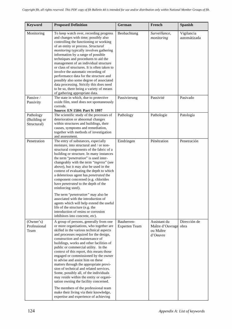
124 Appendix A: List of keywords
Keyword Proposed Definition German French Spanish
Monitoring To keep watch over, recording progress and changes with time; possibly also controlling the functioning or working of an entity or process. Structural monitoring typically involves gathering information by a range of possible techniques and procedures to aid the management of an individual structure or class of structures. It is often taken to involve the automatic recording of performance data for the structure and possibly also some degree of associated data processing. Strictly this does need to be so, there being a variety of means of gathering appropriate data.
Beobachtung Surveillance, monitoring
Vigilancia automátizada
Passive / Passivity
The state in which, due to protective oxide film, steel does not spontaneously corrode. Source: EN 1504: Part 9: 1997
Passivierung Passivité Pasivado
Pathology (Building or Structural)
The scientific study of the processes of deterioration or abnormal changes within structures and buildings, their causes, symptoms and remediation, together with methods of investigation and assessment.
Pathology Pathologie Patología
Penetration The entry of substances, especially moisture, into structural and / or non-structural components of the fabric of a building or structure. In many instances the term “penetration” is used inter-changeably with the term “ingress” (see above), but it may also be used in the context of evaluating the depth to which a deleterious agent has penetrated the component concerned (e.g. chlorides have penetrated to the depth of the reinforcing steel).
The term “penetration” may also be associated with the introduction of agents which will help extend the useful life of the structure (e.g. the introduction of resins or corrosion inhibitors into concrete, etc).
Eindringen Pénétration Penetración
(Owner’s) Professional Team
A group of persons, generally from one or more organisations, who together are skilled in the various technical aspects and processes required for the design, construction and maintenance of buildings, works and other facilities of public or commercial utility. In the context of this report, this means those engaged or commissioned by the owner to advise and assist him on these matters through the appropriate provi-sion of technical and related services. Some, possibly all, of the individuals may reside within the entity or organi-sation owning the facility concerned.
The members of the professional team make their living via their knowledge, expertise and experience of achieving
Bauherren- Experten Team
Assistant du Maître d’Ouvrage ou Maître d’Oeuvre
Dirección de obra
Copyright fib, all rights reserved. This PDF copy of fib Bulletin 44 is intended for use and/or distribution only within National Member Groups of fib.
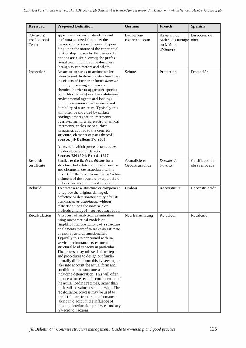
fib Bulletin 44: Concrete structure management: Guide to ownership and good practice 125
Keyword Proposed Definition German French Spanish
(Owner’s) Professional Team
appropriate technical standards and performance needed to meet the owner’s stated requirements. Depen-ding upon the nature of the contractual relationship chosen by the owner (the options are quite diverse); the profes-sional team might include designers through to contractors and others.
Bauherren- Experten Team
Assistant du Maître d’Ouvrage ou Maître d’Oeuvre
Dirección de obra
Protection An action or series of actions under-taken to seek to defend a structure from the effects of further or future deterior-ation by providing a physical or chemical barrier to aggressive species (e.g. chloride ions) or other deleterious environmental agents and loadings upon the in-service performance and durability of a structure. Typically this will often be provided by surface coatings, impregnation treatments, overlays, membranes, electro-chemical treatments, enclosure or surface wrappings applied to the concrete structure, elements or parts thereof. Source: fib Bulletin 17: 2002
A measure which prevents or reduces the development of defects. Source: EN 1504: Part 9: 1997
Schutz Protection Protección
Re-birth certificate
Similar to the Birth certificate for a structure, but relates to the information and circumstances associated with a project for the repair/remediation/ refur-bishment of the structure or a part there-of to extend its anticipated service life.
Aktualisierte Geburtsurkunde
Dossier de travaux
Certificado de obra renovada
Rebuild To create a new structure or component to replace the original damaged, defective or deteriorated entity after its destruction or demolition, without restriction upon the materials or methods employed - see reconstruction.
Umbau Reconstruire Reconstrucción
Recalculation A process of analytical examination using mathematical models or simplified representations of a structure or elements thereof to make an estimate of their structural functionality. Typically this is concerned with in-service performance assessment and structural load capacity in particular. The process may utilise similar steps and procedures to design but funda-mentally differs from this by seeking to take into account the actual form and condition of the structure as found, including deterioration. This will often include a more realistic consideration of the actual loading regimes, rather than the idealised values used in design. The recalculation process may be used to predict future structural performance taking into account the influence of ongoing deterioration processes and any remediation actions.
Neu-Berechnung Re-calcul Recálculo
Copyright fib, all rights reserved. This PDF copy of fib Bulletin 44 is intended for use and/or distribution only within National Member Groups of fib.
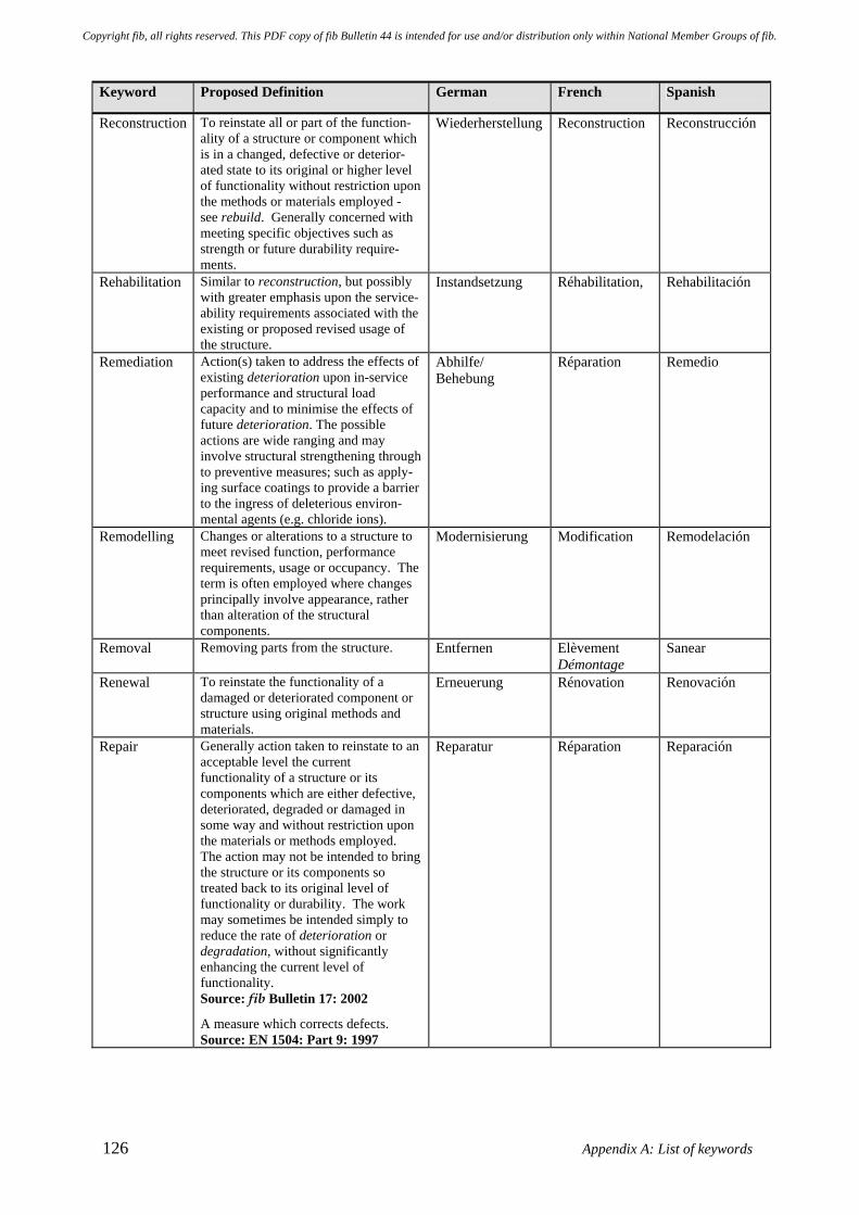
126 Appendix A: List of keywords
Keyword Proposed Definition German French Spanish
Reconstruction To reinstate all or part of the function-ality of a structure or component which is in a changed, defective or deterior-ated state to its original or higher level of functionality without restriction upon the methods or materials employed - see rebuild. Generally concerned with meeting specific objectives such as strength or future durability require-ments.
Wiederherstellung Reconstruction Reconstrucción
Rehabilitation Similar to reconstruction, but possibly with greater emphasis upon the service-ability requirements associated with the existing or proposed revised usage of the structure.
Instandsetzung Réhabilitation,
Rehabilitación
Remediation Action(s) taken to address the effects of existing deterioration upon in-service performance and structural load capacity and to minimise the effects of future deterioration. The possible actions are wide ranging and may involve structural strengthening through to preventive measures; such as apply-ing surface coatings to provide a barrier to the ingress of deleterious environ-mental agents (e.g. chloride ions).
Abhilfe/ Behebung
Réparation Remedio
Remodelling Changes or alterations to a structure to meet revised function, performance requirements, usage or occupancy. The term is often employed where changes principally involve appearance, rather than alteration of the structural components.
Modernisierung Modification Remodelación
Removal Removing parts from the structure. Entfernen Elèvement Démontage
Sanear
Renewal To reinstate the functionality of a damaged or deteriorated component or structure using original methods and materials.
Erneuerung Rénovation Renovación
Repair Generally action taken to reinstate to an acceptable level the current functionality of a structure or its components which are either defective, deteriorated, degraded or damaged in some way and without restriction upon the materials or methods employed. The action may not be intended to bring the structure or its components so treated back to its original level of functionality or durability. The work may sometimes be intended simply to reduce the rate of deterioration or degradation, without significantly enhancing the current level of functionality. Source: fib Bulletin 17: 2002
A measure which corrects defects. Source: EN 1504: Part 9: 1997
Reparatur Réparation Reparación
Copyright fib, all rights reserved. This PDF copy of fib Bulletin 44 is intended for use and/or distribution only within National Member Groups of fib.
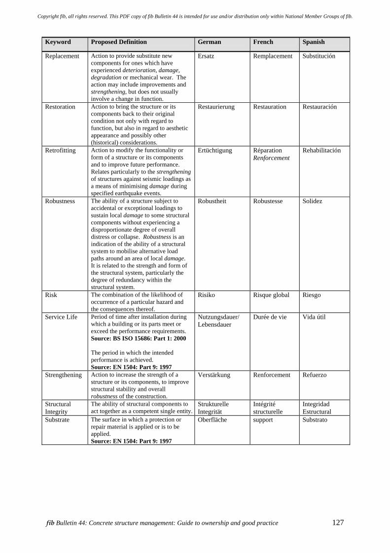
fib Bulletin 44: Concrete structure management: Guide to ownership and good practice 127
Keyword Proposed Definition German French Spanish
Replacement Action to provide substitute new components for ones which have experienced deterioration, damage, degradation or mechanical wear. The action may include improvements and strengthening, but does not usually involve a change in function.
Ersatz Remplacement Substitución
Restoration Action to bring the structure or its components back to their original condition not only with regard to function, but also in regard to aesthetic appearance and possibly other (historical) considerations.
Restaurierung Restauration Restauración
Retrofitting Action to modify the functionality or form of a structure or its components and to improve future performance. Relates particularly to the strengthening of structures against seismic loadings as a means of minimising damage during specified earthquake events.
Ertüchtigung Réparation Renforcement
Rehabilitación
Robustness The ability of a structure subject to accidental or exceptional loadings to sustain local damage to some structural components without experiencing a disproportionate degree of overall distress or collapse. Robustness is an indication of the ability of a structural system to mobilise alternative load paths around an area of local damage. It is related to the strength and form of the structural system, particularly the degree of redundancy within the structural system.
Robustheit Robustesse Solidez
Risk The combination of the likelihood of occurrence of a particular hazard and the consequences thereof.
Risiko Risque global Riesgo
Service Life
Period of time after installation during which a building or its parts meet or exceed the performance requirements. Source: BS ISO 15686: Part 1: 2000 The period in which the intended performance is achieved. Source: EN 1504: Part 9: 1997
Nutzungsdauer/ Lebensdauer
Durée de vie Vida útil
Strengthening Action to increase the strength of a structure or its components, to improve structural stability and overall robustness of the construction.
Verstärkung Renforcement Refuerzo
Structural Integrity
The ability of structural components to act together as a competent single entity.
Strukturelle Integrität
Intégrité structurelle
Integridad Estructural
Substrate
The surface in which a protection or repair material is applied or is to be applied. Source: EN 1504: Part 9: 1997
Oberfläche support Substrato
Copyright fib, all rights reserved. This PDF copy of fib Bulletin 44 is intended for use and/or distribution only within National Member Groups of fib.
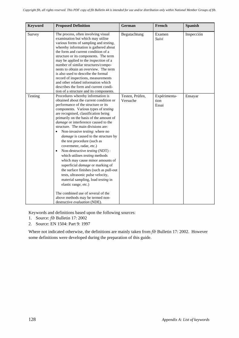
128 Appendix A: List of keywords
Keyword Proposed Definition German French Spanish
Survey The process, often involving visual examination but which may utilise various forms of sampling and testing, whereby information is gathered about the form and current condition of a structure or its components. The term may be applied to the inspection of a number of similar structures/compo-nents to obtain an overview. The term is also used to describe the formal record of inspections, measurements and other related information which describes the form and current condi-tion of a structure and its components.
Begutachtung Examen Suivi
Inspección
Testing Procedures whereby information is obtained about the current condition or performance of the structure or its components. Various types of testing are recognised, classification being primarily on the basis of the amount of damage or interference caused to the structure. The main divisions are: • Non-invasive testing: where no
damage is caused to the structure by the test procedure (such as covermeter, radar, etc.)
• Non-destructive testing (NDT) : which utilises testing methods which may cause minor amounts of superficial damage or marking of the surface finishes (such as pull-out tests, ultrasonic pulse velocity, material sampling, load testing in elastic range, etc.)
The combined use of several of the above methods may be termed non-destructive evaluation (NDE).
Testen, Prüfen, Versuche
Expérimenta-tion Essai
Ensayar
Keywords and definitions based upon the following sources: 1. Source: fib Bulletin 17: 2002 2. Source: EN 1504: Part 9: 1997
Where not indicated otherwise, the definitions are mainly taken from fib Bulletin 17: 2002. However some definitions were developed during the preparation of this guide.
Copyright fib, all rights reserved. This PDF copy of fib Bulletin 44 is intended for use and/or distribution only within National Member Groups of fib.
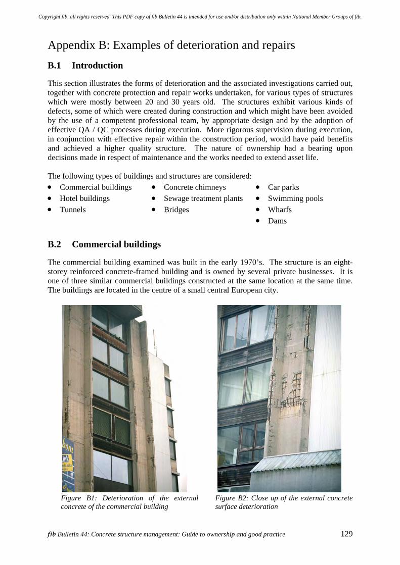
fib Bulletin 44: Concrete structure management: Guide to ownership and good practice 129
Appendix B: Examples of deterioration and repairs B.1 Introduction
This section illustrates the forms of deterioration and the associated investigations carried out, together with concrete protection and repair works undertaken, for various types of structures which were mostly between 20 and 30 years old. The structures exhibit various kinds of defects, some of which were created during construction and which might have been avoided by the use of a competent professional team, by appropriate design and by the adoption of effective QA / QC processes during execution. More rigorous supervision during execution, in conjunction with effective repair within the construction period, would have paid benefits and achieved a higher quality structure. The nature of ownership had a bearing upon decisions made in respect of maintenance and the works needed to extend asset life. The following types of buildings and structures are considered: • Commercial buildings • Hotel buildings • Tunnels
• Concrete chimneys • Sewage treatment plants • Bridges
• Car parks • Swimming pools • Wharfs • Dams
B.2 Commercial buildings
The commercial building examined was built in the early 1970’s. The structure is an eight-storey reinforced concrete-framed building and is owned by several private businesses. It is one of three similar commercial buildings constructed at the same location at the same time. The buildings are located in the centre of a small central European city.
Figure B1: Deterioration of the external concrete of the commercial building
Figure B2: Close up of the external concrete surface deterioration
Copyright fib, all rights reserved. This PDF copy of fib Bulletin 44 is intended for use and/or distribution only within National Member Groups of fib.
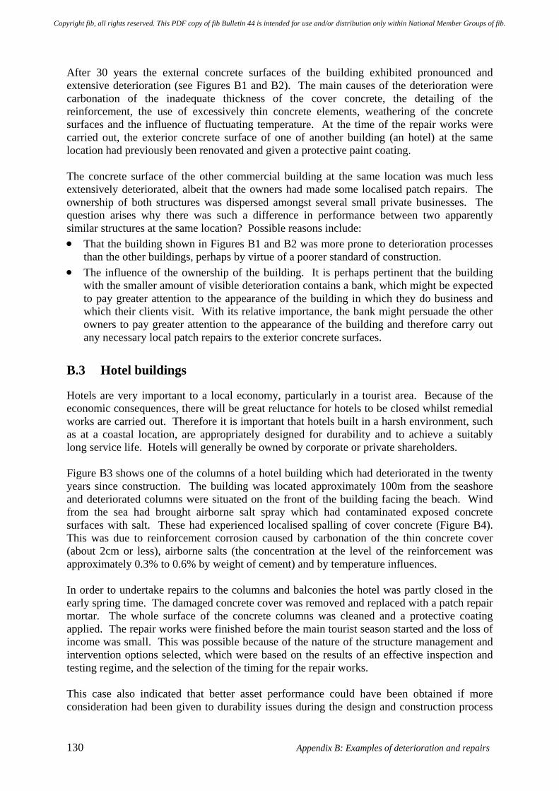
130 Appendix B: Examples of deterioration and repairs
After 30 years the external concrete surfaces of the building exhibited pronounced and extensive deterioration (see Figures B1 and B2). The main causes of the deterioration were carbonation of the inadequate thickness of the cover concrete, the detailing of the reinforcement, the use of excessively thin concrete elements, weathering of the concrete surfaces and the influence of fluctuating temperature. At the time of the repair works were carried out, the exterior concrete surface of one of another building (an hotel) at the same location had previously been renovated and given a protective paint coating. The concrete surface of the other commercial building at the same location was much less extensively deteriorated, albeit that the owners had made some localised patch repairs. The ownership of both structures was dispersed amongst several small private businesses. The question arises why there was such a difference in performance between two apparently similar structures at the same location? Possible reasons include: • That the building shown in Figures B1 and B2 was more prone to deterioration processes
than the other buildings, perhaps by virtue of a poorer standard of construction. • The influence of the ownership of the building. It is perhaps pertinent that the building
with the smaller amount of visible deterioration contains a bank, which might be expected to pay greater attention to the appearance of the building in which they do business and which their clients visit. With its relative importance, the bank might persuade the other owners to pay greater attention to the appearance of the building and therefore carry out any necessary local patch repairs to the exterior concrete surfaces.
B.3 Hotel buildings
Hotels are very important to a local economy, particularly in a tourist area. Because of the economic consequences, there will be great reluctance for hotels to be closed whilst remedial works are carried out. Therefore it is important that hotels built in a harsh environment, such as at a coastal location, are appropriately designed for durability and to achieve a suitably long service life. Hotels will generally be owned by corporate or private shareholders. Figure B3 shows one of the columns of a hotel building which had deteriorated in the twenty years since construction. The building was located approximately 100m from the seashore and deteriorated columns were situated on the front of the building facing the beach. Wind from the sea had brought airborne salt spray which had contaminated exposed concrete surfaces with salt. These had experienced localised spalling of cover concrete (Figure B4). This was due to reinforcement corrosion caused by carbonation of the thin concrete cover (about 2cm or less), airborne salts (the concentration at the level of the reinforcement was approximately 0.3% to 0.6% by weight of cement) and by temperature influences. In order to undertake repairs to the columns and balconies the hotel was partly closed in the early spring time. The damaged concrete cover was removed and replaced with a patch repair mortar. The whole surface of the concrete columns was cleaned and a protective coating applied. The repair works were finished before the main tourist season started and the loss of income was small. This was possible because of the nature of the structure management and intervention options selected, which were based on the results of an effective inspection and testing regime, and the selection of the timing for the repair works. This case also indicated that better asset performance could have been obtained if more consideration had been given to durability issues during the design and construction process
Copyright fib, all rights reserved. This PDF copy of fib Bulletin 44 is intended for use and/or distribution only within National Member Groups of fib.
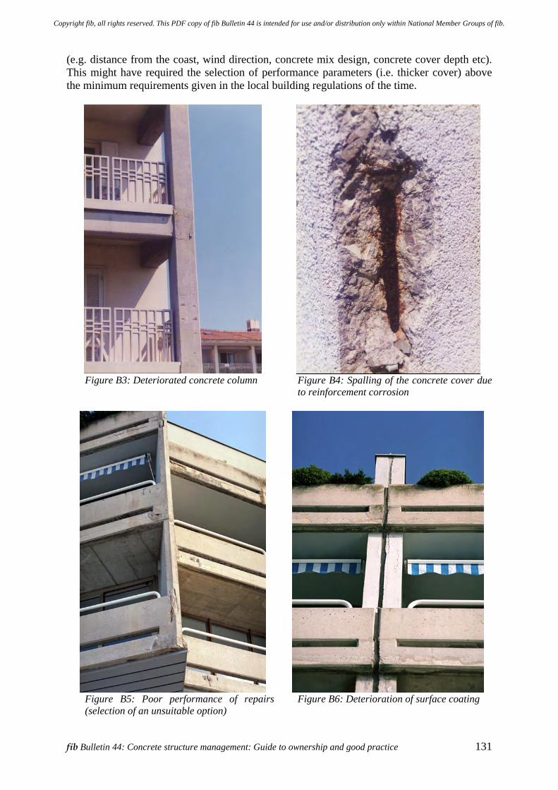
fib Bulletin 44: Concrete structure management: Guide to ownership and good practice 131
(e.g. distance from the coast, wind direction, concrete mix design, concrete cover depth etc). This might have required the selection of performance parameters (i.e. thicker cover) above the minimum requirements given in the local building regulations of the time.
Figure B3: Deteriorated concrete column
Figure B4: Spalling of the concrete cover due to reinforcement corrosion
Figure B5: Poor performance of repairs (selection of an unsuitable option)
Figure B6: Deterioration of surface coating
Copyright fib, all rights reserved. This PDF copy of fib Bulletin 44 is intended for use and/or distribution only within National Member Groups of fib.
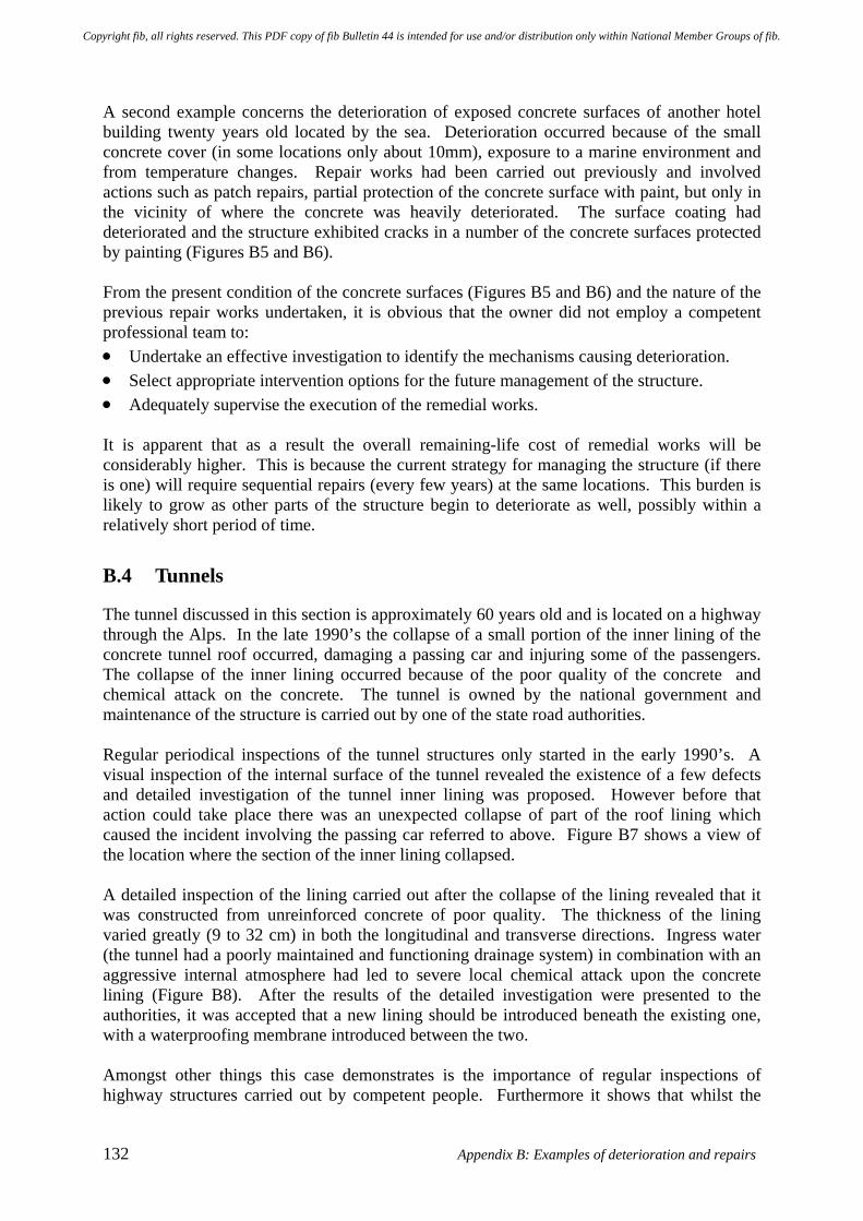
132 Appendix B: Examples of deterioration and repairs
A second example concerns the deterioration of exposed concrete surfaces of another hotel building twenty years old located by the sea. Deterioration occurred because of the small concrete cover (in some locations only about 10mm), exposure to a marine environment and from temperature changes. Repair works had been carried out previously and involved actions such as patch repairs, partial protection of the concrete surface with paint, but only in the vicinity of where the concrete was heavily deteriorated. The surface coating had deteriorated and the structure exhibited cracks in a number of the concrete surfaces protected by painting (Figures B5 and B6). From the present condition of the concrete surfaces (Figures B5 and B6) and the nature of the previous repair works undertaken, it is obvious that the owner did not employ a competent professional team to: • Undertake an effective investigation to identify the mechanisms causing deterioration. • Select appropriate intervention options for the future management of the structure. • Adequately supervise the execution of the remedial works. It is apparent that as a result the overall remaining-life cost of remedial works will be considerably higher. This is because the current strategy for managing the structure (if there is one) will require sequential repairs (every few years) at the same locations. This burden is likely to grow as other parts of the structure begin to deteriorate as well, possibly within a relatively short period of time.
B.4 Tunnels
The tunnel discussed in this section is approximately 60 years old and is located on a highway through the Alps. In the late 1990’s the collapse of a small portion of the inner lining of the concrete tunnel roof occurred, damaging a passing car and injuring some of the passengers. The collapse of the inner lining occurred because of the poor quality of the concrete and chemical attack on the concrete. The tunnel is owned by the national government and maintenance of the structure is carried out by one of the state road authorities. Regular periodical inspections of the tunnel structures only started in the early 1990’s. A visual inspection of the internal surface of the tunnel revealed the existence of a few defects and detailed investigation of the tunnel inner lining was proposed. However before that action could take place there was an unexpected collapse of part of the roof lining which caused the incident involving the passing car referred to above. Figure B7 shows a view of the location where the section of the inner lining collapsed. A detailed inspection of the lining carried out after the collapse of the lining revealed that it was constructed from unreinforced concrete of poor quality. The thickness of the lining varied greatly (9 to 32 cm) in both the longitudinal and transverse directions. Ingress water (the tunnel had a poorly maintained and functioning drainage system) in combination with an aggressive internal atmosphere had led to severe local chemical attack upon the concrete lining (Figure B8). After the results of the detailed investigation were presented to the authorities, it was accepted that a new lining should be introduced beneath the existing one, with a waterproofing membrane introduced between the two. Amongst other things this case demonstrates is the importance of regular inspections of highway structures carried out by competent people. Furthermore it shows that whilst the
Copyright fib, all rights reserved. This PDF copy of fib Bulletin 44 is intended for use and/or distribution only within National Member Groups of fib.
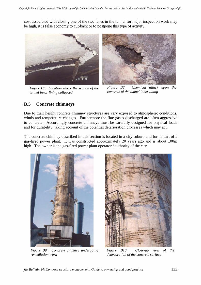
fib Bulletin 44: Concrete structure management: Guide to ownership and good practice 133
cost associated with closing one of the two lanes in the tunnel for major inspection work may be high, it is false economy to cut-back or to postpone this type of activity.
Figure B7: Location where the section of the tunnel inner lining collapsed
Figure B8: Chemical attack upon the concrete of the tunnel inner lining
B.5 Concrete chimneys
Due to their height concrete chimney structures are very exposed to atmospheric conditions, winds and temperature changes. Furthermore the flue gases discharged are often aggressive to concrete. Accordingly concrete chimneys must be carefully designed for physical loads and for durability, taking account of the potential deterioration processes which may act. The concrete chimney described in this section is located in a city suburb and forms part of a gas-fired power plant. It was constructed approximately 20 years ago and is about 100m high. The owner is the gas-fired power plant operator / authority of the city.
Figure B9: Concrete chimney undergoing remediation work
Figure B10: Close-up view of the deterioration of the concrete surface
Copyright fib, all rights reserved. This PDF copy of fib Bulletin 44 is intended for use and/or distribution only within National Member Groups of fib.
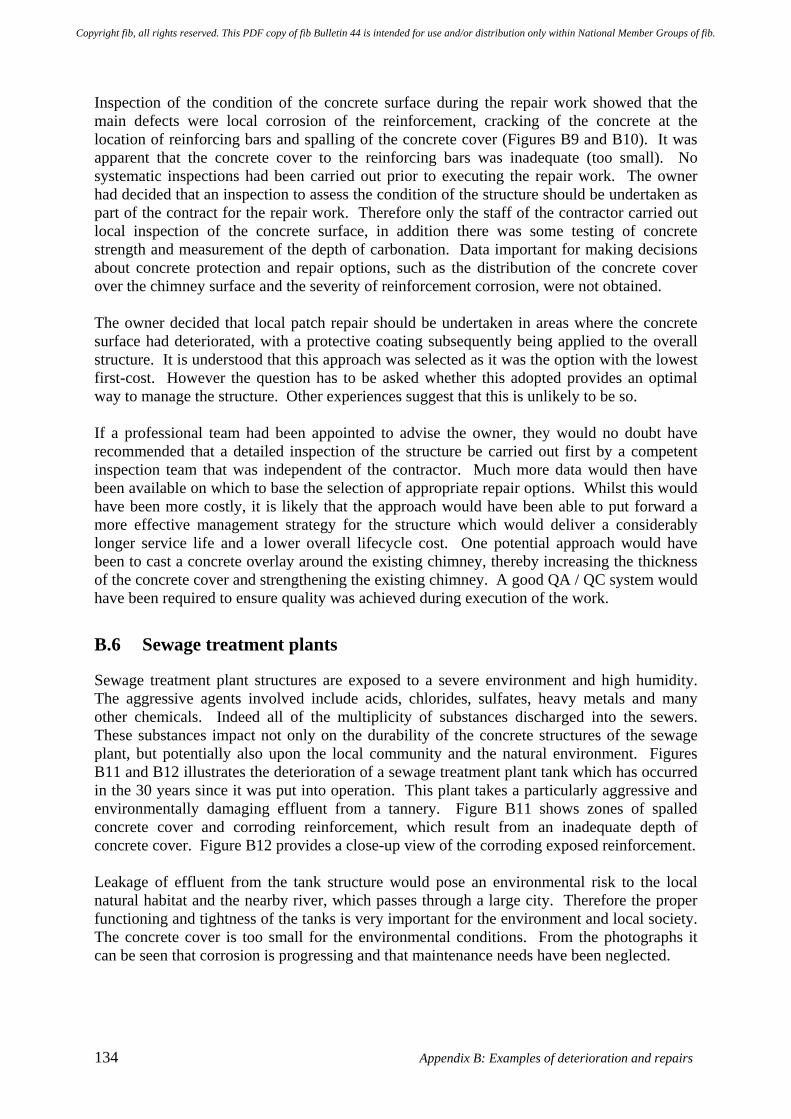
134 Appendix B: Examples of deterioration and repairs
Inspection of the condition of the concrete surface during the repair work showed that the main defects were local corrosion of the reinforcement, cracking of the concrete at the location of reinforcing bars and spalling of the concrete cover (Figures B9 and B10). It was apparent that the concrete cover to the reinforcing bars was inadequate (too small). No systematic inspections had been carried out prior to executing the repair work. The owner had decided that an inspection to assess the condition of the structure should be undertaken as part of the contract for the repair work. Therefore only the staff of the contractor carried out local inspection of the concrete surface, in addition there was some testing of concrete strength and measurement of the depth of carbonation. Data important for making decisions about concrete protection and repair options, such as the distribution of the concrete cover over the chimney surface and the severity of reinforcement corrosion, were not obtained. The owner decided that local patch repair should be undertaken in areas where the concrete surface had deteriorated, with a protective coating subsequently being applied to the overall structure. It is understood that this approach was selected as it was the option with the lowest first-cost. However the question has to be asked whether this adopted provides an optimal way to manage the structure. Other experiences suggest that this is unlikely to be so. If a professional team had been appointed to advise the owner, they would no doubt have recommended that a detailed inspection of the structure be carried out first by a competent inspection team that was independent of the contractor. Much more data would then have been available on which to base the selection of appropriate repair options. Whilst this would have been more costly, it is likely that the approach would have been able to put forward a more effective management strategy for the structure which would deliver a considerably longer service life and a lower overall lifecycle cost. One potential approach would have been to cast a concrete overlay around the existing chimney, thereby increasing the thickness of the concrete cover and strengthening the existing chimney. A good QA / QC system would have been required to ensure quality was achieved during execution of the work.
B.6 Sewage treatment plants
Sewage treatment plant structures are exposed to a severe environment and high humidity. The aggressive agents involved include acids, chlorides, sulfates, heavy metals and many other chemicals. Indeed all of the multiplicity of substances discharged into the sewers. These substances impact not only on the durability of the concrete structures of the sewage plant, but potentially also upon the local community and the natural environment. Figures B11 and B12 illustrates the deterioration of a sewage treatment plant tank which has occurred in the 30 years since it was put into operation. This plant takes a particularly aggressive and environmentally damaging effluent from a tannery. Figure B11 shows zones of spalled concrete cover and corroding reinforcement, which result from an inadequate depth of concrete cover. Figure B12 provides a close-up view of the corroding exposed reinforcement. Leakage of effluent from the tank structure would pose an environmental risk to the local natural habitat and the nearby river, which passes through a large city. Therefore the proper functioning and tightness of the tanks is very important for the environment and local society. The concrete cover is too small for the environmental conditions. From the photographs it can be seen that corrosion is progressing and that maintenance needs have been neglected.
Copyright fib, all rights reserved. This PDF copy of fib Bulletin 44 is intended for use and/or distribution only within National Member Groups of fib.
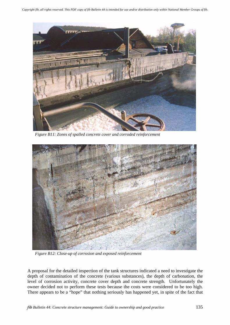
fib Bulletin 44: Concrete structure management: Guide to ownership and good practice 135
Figure B11: Zones of spalled concrete cover and corroded reinforcement
Figure B12: Close-up of corrosion and exposed reinforcement
A proposal for the detailed inspection of the tank structures indicated a need to investigate the depth of contamination of the concrete (various substances), the depth of carbonation, the level of corrosion activity, concrete cover depth and concrete strength. Unfortunately the owner decided not to perform these tests because the costs were considered to be too high. There appears to be a “hope” that nothing seriously has happened yet, in spite of the fact that
Copyright fib, all rights reserved. This PDF copy of fib Bulletin 44 is intended for use and/or distribution only within National Member Groups of fib.
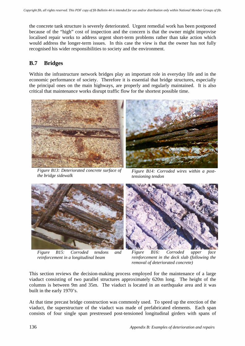
136 Appendix B: Examples of deterioration and repairs
the concrete tank structure is severely deteriorated. Urgent remedial work has been postponed because of the “high” cost of inspection and the concern is that the owner might improvise localised repair works to address urgent short-term problems rather than take action which would address the longer-term issues. In this case the view is that the owner has not fully recognised his wider responsibilities to society and the environment.
B.7 Bridges
Within the infrastructure network bridges play an important role in everyday life and in the economic performance of society. Therefore it is essential that bridge structures, especially the principal ones on the main highways, are properly and regularly maintained. It is also critical that maintenance works disrupt traffic flow for the shortest possible time.
Figure B13: Deteriorated concrete surface of the bridge sidewalk
Figure B14: Corroded wires within a post-tensioning tendon
Figure B15: Corroded tendons and reinforcement in a longitudinal beam
Figure B16: Corroded upper face reinforcement in the deck slab (following the removal of deteriorated concrete)
This section reviews the decision-making process employed for the maintenance of a large viaduct consisting of two parallel structures approximately 620m long. The height of the columns is between 9m and 35m. The viaduct is located in an earthquake area and it was built in the early 1970’s. At that time precast bridge construction was commonly used. To speed up the erection of the viaduct, the superstructure of the viaduct was made of prefabricated elements. Each span consists of four single span prestressed post-tensioned longitudinal girders with spans of
Copyright fib, all rights reserved. This PDF copy of fib Bulletin 44 is intended for use and/or distribution only within National Member Groups of fib.
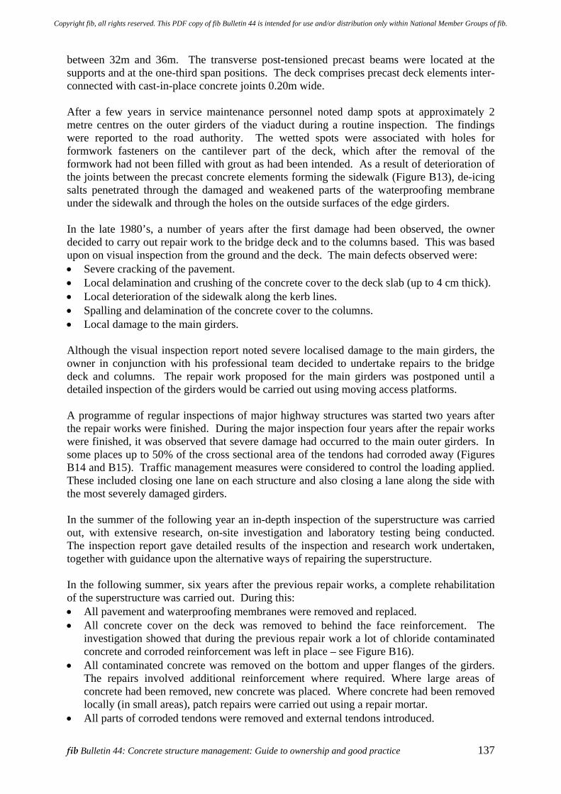
fib Bulletin 44: Concrete structure management: Guide to ownership and good practice 137
between 32m and 36m. The transverse post-tensioned precast beams were located at the supports and at the one-third span positions. The deck comprises precast deck elements inter-connected with cast-in-place concrete joints 0.20m wide. After a few years in service maintenance personnel noted damp spots at approximately 2 metre centres on the outer girders of the viaduct during a routine inspection. The findings were reported to the road authority. The wetted spots were associated with holes for formwork fasteners on the cantilever part of the deck, which after the removal of the formwork had not been filled with grout as had been intended. As a result of deterioration of the joints between the precast concrete elements forming the sidewalk (Figure B13), de-icing salts penetrated through the damaged and weakened parts of the waterproofing membrane under the sidewalk and through the holes on the outside surfaces of the edge girders. In the late 1980’s, a number of years after the first damage had been observed, the owner decided to carry out repair work to the bridge deck and to the columns based. This was based upon on visual inspection from the ground and the deck. The main defects observed were: • Severe cracking of the pavement. • Local delamination and crushing of the concrete cover to the deck slab (up to 4 cm thick). • Local deterioration of the sidewalk along the kerb lines. • Spalling and delamination of the concrete cover to the columns. • Local damage to the main girders. Although the visual inspection report noted severe localised damage to the main girders, the owner in conjunction with his professional team decided to undertake repairs to the bridge deck and columns. The repair work proposed for the main girders was postponed until a detailed inspection of the girders would be carried out using moving access platforms. A programme of regular inspections of major highway structures was started two years after the repair works were finished. During the major inspection four years after the repair works were finished, it was observed that severe damage had occurred to the main outer girders. In some places up to 50% of the cross sectional area of the tendons had corroded away (Figures B14 and B15). Traffic management measures were considered to control the loading applied. These included closing one lane on each structure and also closing a lane along the side with the most severely damaged girders. In the summer of the following year an in-depth inspection of the superstructure was carried out, with extensive research, on-site investigation and laboratory testing being conducted. The inspection report gave detailed results of the inspection and research work undertaken, together with guidance upon the alternative ways of repairing the superstructure. In the following summer, six years after the previous repair works, a complete rehabilitation of the superstructure was carried out. During this: • All pavement and waterproofing membranes were removed and replaced. • All concrete cover on the deck was removed to behind the face reinforcement. The
investigation showed that during the previous repair work a lot of chloride contaminated concrete and corroded reinforcement was left in place – see Figure B16).
• All contaminated concrete was removed on the bottom and upper flanges of the girders. The repairs involved additional reinforcement where required. Where large areas of concrete had been removed, new concrete was placed. Where concrete had been removed locally (in small areas), patch repairs were carried out using a repair mortar.
• All parts of corroded tendons were removed and external tendons introduced.
Copyright fib, all rights reserved. This PDF copy of fib Bulletin 44 is intended for use and/or distribution only within National Member Groups of fib.
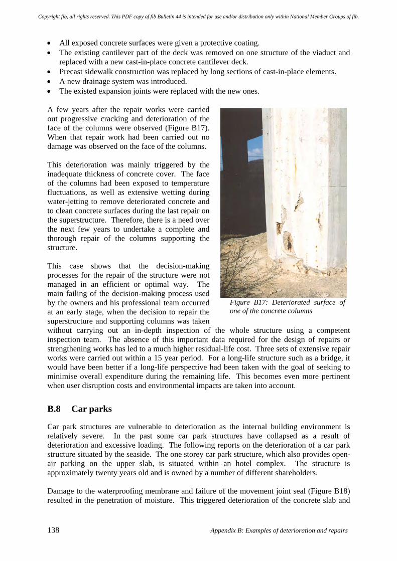
138 Appendix B: Examples of deterioration and repairs
• All exposed concrete surfaces were given a protective coating. • The existing cantilever part of the deck was removed on one structure of the viaduct and
replaced with a new cast-in-place concrete cantilever deck. • Precast sidewalk construction was replaced by long sections of cast-in-place elements. • A new drainage system was introduced. • The existed expansion joints were replaced with the new ones. A few years after the repair works were carried out progressive cracking and deterioration of the face of the columns were observed (Figure B17). When that repair work had been carried out no damage was observed on the face of the columns. This deterioration was mainly triggered by the inadequate thickness of concrete cover. The face of the columns had been exposed to temperature fluctuations, as well as extensive wetting during water-jetting to remove deteriorated concrete and to clean concrete surfaces during the last repair on the superstructure. Therefore, there is a need over the next few years to undertake a complete and thorough repair of the columns supporting the structure. This case shows that the decision-making processes for the repair of the structure were not managed in an efficient or optimal way. The main failing of the decision-making process used by the owners and his professional team occurred at an early stage, when the decision to repair the superstructure and supporting columns was taken without carrying out an in-depth inspection of the whole structure using a competent inspection team. The absence of this important data required for the design of repairs or strengthening works has led to a much higher residual-life cost. Three sets of extensive repair works were carried out within a 15 year period. For a long-life structure such as a bridge, it would have been better if a long-life perspective had been taken with the goal of seeking to minimise overall expenditure during the remaining life. This becomes even more pertinent when user disruption costs and environmental impacts are taken into account.
B.8 Car parks
Car park structures are vulnerable to deterioration as the internal building environment is relatively severe. In the past some car park structures have collapsed as a result of deterioration and excessive loading. The following reports on the deterioration of a car park structure situated by the seaside. The one storey car park structure, which also provides open-air parking on the upper slab, is situated within an hotel complex. The structure is approximately twenty years old and is owned by a number of different shareholders. Damage to the waterproofing membrane and failure of the movement joint seal (Figure B18) resulted in the penetration of moisture. This triggered deterioration of the concrete slab and
Figure B17: Deteriorated surface of one of the concrete columns
Copyright fib, all rights reserved. This PDF copy of fib Bulletin 44 is intended for use and/or distribution only within National Member Groups of fib.
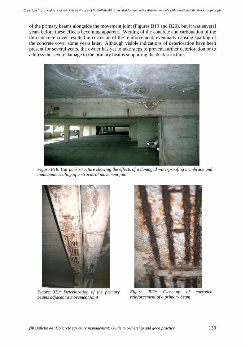
fib Bulletin 44: Concrete structure management: Guide to ownership and good practice 139
of the primary beams alongside the movement joint (Figures B19 and B20), but it was several years before these effects becoming apparent. Wetting of the concrete and carbonation of the thin concrete cover resulted in corrosion of the reinforcement, eventually causing spalling of the concrete cover some years later. Although visible indications of deterioration have been present for several years, the owner has yet to take steps to prevent further deterioration or to address the severe damage to the primary beams supporting the deck structure.
Figure B18: Car park structure showing the effects of a damaged waterproofing membrane and inadequate sealing of a structural movement joint
Figure B19: Deterioration of the primary beams adjacent a movement joint
Figure B20: Close–up of corroded reinforcement of a primary beam
Copyright fib, all rights reserved. This PDF copy of fib Bulletin 44 is intended for use and/or distribution only within National Member Groups of fib.
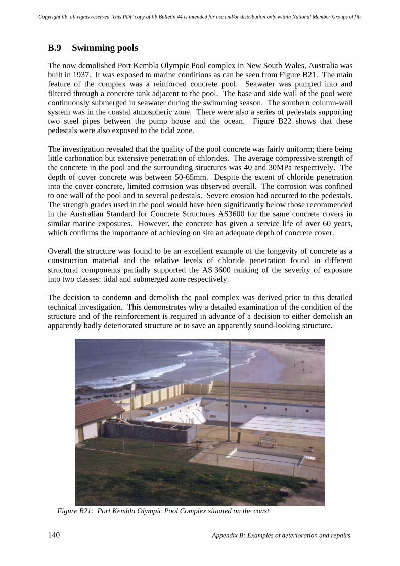
140 Appendix B: Examples of deterioration and repairs
B.9 Swimming pools
The now demolished Port Kembla Olympic Pool complex in New South Wales, Australia was built in 1937. It was exposed to marine conditions as can be seen from Figure B21. The main feature of the complex was a reinforced concrete pool. Seawater was pumped into and filtered through a concrete tank adjacent to the pool. The base and side wall of the pool were continuously submerged in seawater during the swimming season. The southern column-wall system was in the coastal atmospheric zone. There were also a series of pedestals supporting two steel pipes between the pump house and the ocean. Figure B22 shows that these pedestals were also exposed to the tidal zone. The investigation revealed that the quality of the pool concrete was fairly uniform; there being little carbonation but extensive penetration of chlorides. The average compressive strength of the concrete in the pool and the surrounding structures was 40 and 30MPa respectively. The depth of cover concrete was between 50-65mm. Despite the extent of chloride penetration into the cover concrete, limited corrosion was observed overall. The corrosion was confined to one wall of the pool and to several pedestals. Severe erosion had occurred to the pedestals. The strength grades used in the pool would have been significantly below those recommended in the Australian Standard for Concrete Structures AS3600 for the same concrete covers in similar marine exposures. However, the concrete has given a service life of over 60 years, which confirms the importance of achieving on site an adequate depth of concrete cover. Overall the structure was found to be an excellent example of the longevity of concrete as a construction material and the relative levels of chloride penetration found in different structural components partially supported the AS 3600 ranking of the severity of exposure into two classes: tidal and submerged zone respectively. The decision to condemn and demolish the pool complex was derived prior to this detailed technical investigation. This demonstrates why a detailed examination of the condition of the structure and of the reinforcement is required in advance of a decision to either demolish an apparently badly deteriorated structure or to save an apparently sound-looking structure.
Figure B21: Port Kembla Olympic Pool Complex situated on the coast
Copyright fib, all rights reserved. This PDF copy of fib Bulletin 44 is intended for use and/or distribution only within National Member Groups of fib.
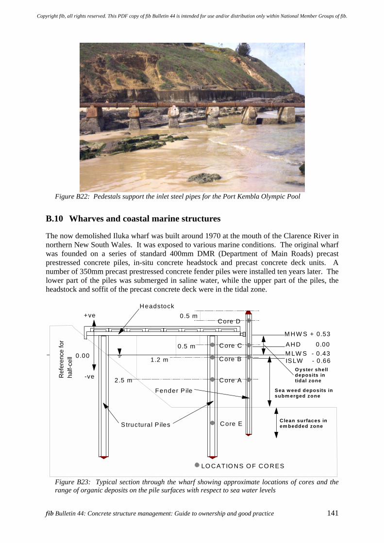
fib Bulletin 44: Concrete structure management: Guide to ownership and good practice 141
Figure B22: Pedestals support the inlet steel pipes for the Port Kembla Olympic Pool
B.10 Wharves and coastal marine structures
The now demolished Iluka wharf was built around 1970 at the mouth of the Clarence River in northern New South Wales. It was exposed to various marine conditions. The original wharf was founded on a series of standard 400mm DMR (Department of Main Roads) precast prestressed concrete piles, in-situ concrete headstock and precast concrete deck units. A number of 350mm precast prestressed concrete fender piles were installed ten years later. The lower part of the piles was submerged in saline water, while the upper part of the piles, the headstock and soffit of the precast concrete deck were in the tidal zone.
2.5 m
0.5 m
1.2 m
0.5 m
LO CATIO NS O F CO RES
M HW S + 0.53
AHD 0.00
ISLW - 0.66M LW S - 0.43
Core E
Core B
Core C
Core A
Core D
Headstock
Structural P iles
Fender P ile
O yster shelldeposits in tidal zone
Sea w eed deposits in subm erged zone
Clean surfaces in em bedded zone
Ref
eren
ce fo
r ha
lf-ce
ll 0 .00
+ve
-ve
Figure B23: Typical section through the wharf showing approximate locations of cores and the range of organic deposits on the pile surfaces with respect to sea water levels
Copyright fib, all rights reserved. This PDF copy of fib Bulletin 44 is intended for use and/or distribution only within National Member Groups of fib.
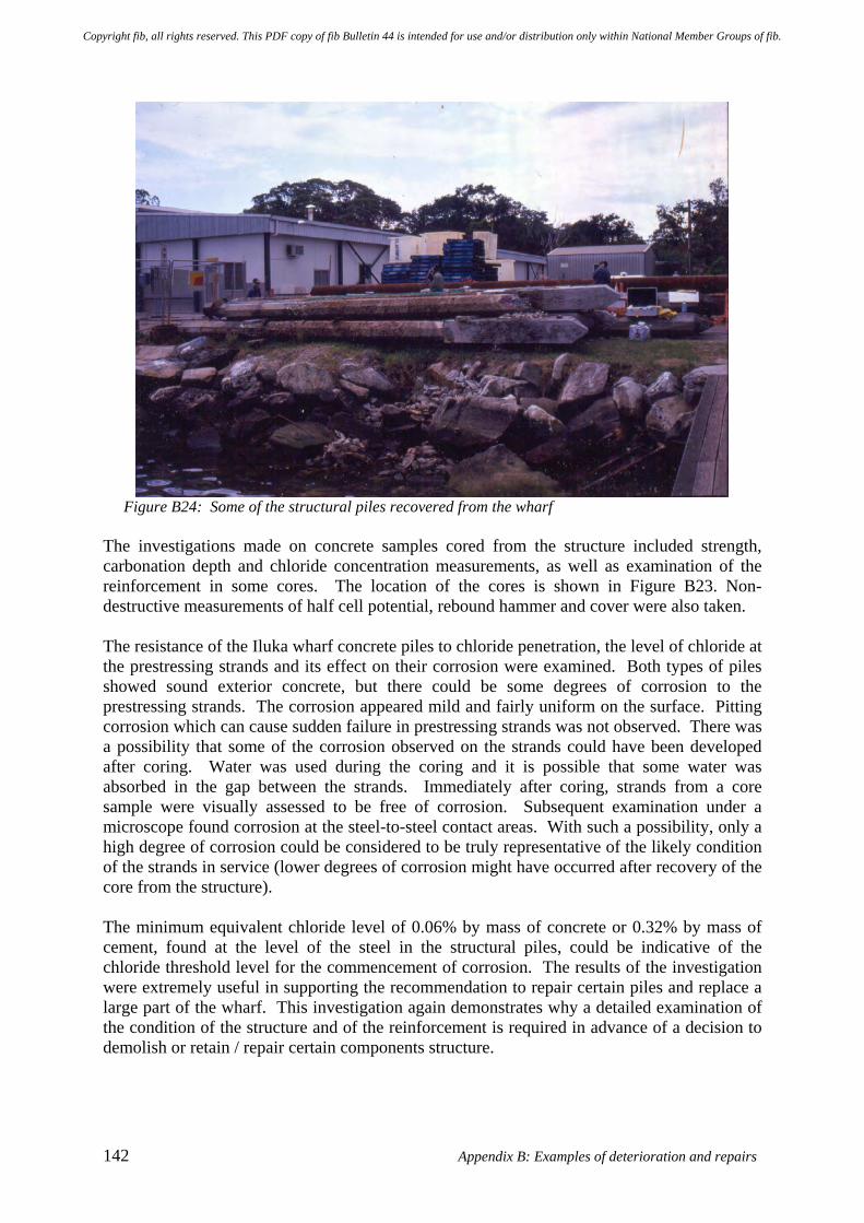
142 Appendix B: Examples of deterioration and repairs
Figure B24: Some of the structural piles recovered from the wharf
The investigations made on concrete samples cored from the structure included strength, carbonation depth and chloride concentration measurements, as well as examination of the reinforcement in some cores. The location of the cores is shown in Figure B23. Non-destructive measurements of half cell potential, rebound hammer and cover were also taken. The resistance of the Iluka wharf concrete piles to chloride penetration, the level of chloride at the prestressing strands and its effect on their corrosion were examined. Both types of piles showed sound exterior concrete, but there could be some degrees of corrosion to the prestressing strands. The corrosion appeared mild and fairly uniform on the surface. Pitting corrosion which can cause sudden failure in prestressing strands was not observed. There was a possibility that some of the corrosion observed on the strands could have been developed after coring. Water was used during the coring and it is possible that some water was absorbed in the gap between the strands. Immediately after coring, strands from a core sample were visually assessed to be free of corrosion. Subsequent examination under a microscope found corrosion at the steel-to-steel contact areas. With such a possibility, only a high degree of corrosion could be considered to be truly representative of the likely condition of the strands in service (lower degrees of corrosion might have occurred after recovery of the core from the structure). The minimum equivalent chloride level of 0.06% by mass of concrete or 0.32% by mass of cement, found at the level of the steel in the structural piles, could be indicative of the chloride threshold level for the commencement of corrosion. The results of the investigation were extremely useful in supporting the recommendation to repair certain piles and replace a large part of the wharf. This investigation again demonstrates why a detailed examination of the condition of the structure and of the reinforcement is required in advance of a decision to demolish or retain / repair certain components structure.
Copyright fib, all rights reserved. This PDF copy of fib Bulletin 44 is intended for use and/or distribution only within National Member Groups of fib.
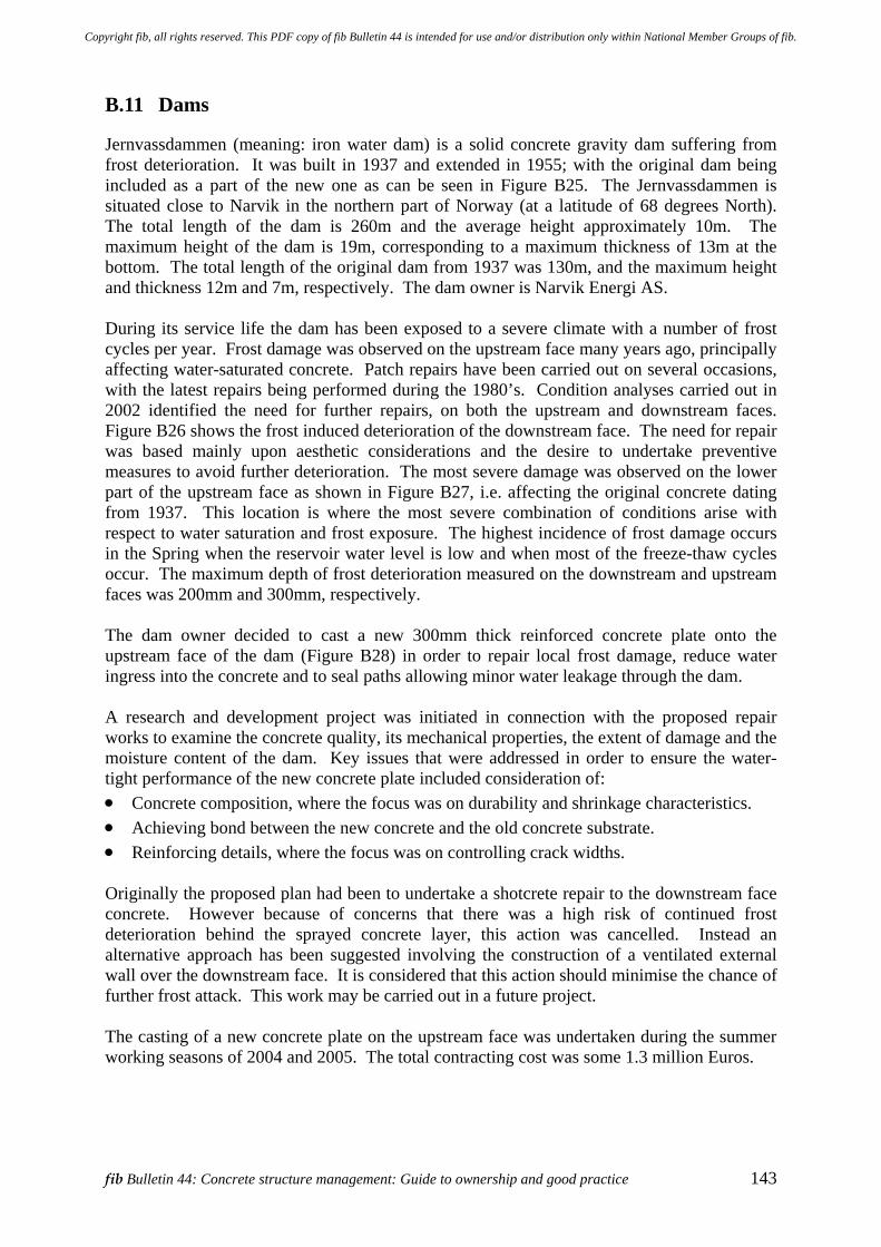
fib Bulletin 44: Concrete structure management: Guide to ownership and good practice 143
B.11 Dams
Jernvassdammen (meaning: iron water dam) is a solid concrete gravity dam suffering from frost deterioration. It was built in 1937 and extended in 1955; with the original dam being included as a part of the new one as can be seen in Figure B25. The Jernvassdammen is situated close to Narvik in the northern part of Norway (at a latitude of 68 degrees North). The total length of the dam is 260m and the average height approximately 10m. The maximum height of the dam is 19m, corresponding to a maximum thickness of 13m at the bottom. The total length of the original dam from 1937 was 130m, and the maximum height and thickness 12m and 7m, respectively. The dam owner is Narvik Energi AS. During its service life the dam has been exposed to a severe climate with a number of frost cycles per year. Frost damage was observed on the upstream face many years ago, principally affecting water-saturated concrete. Patch repairs have been carried out on several occasions, with the latest repairs being performed during the 1980’s. Condition analyses carried out in 2002 identified the need for further repairs, on both the upstream and downstream faces. Figure B26 shows the frost induced deterioration of the downstream face. The need for repair was based mainly upon aesthetic considerations and the desire to undertake preventive measures to avoid further deterioration. The most severe damage was observed on the lower part of the upstream face as shown in Figure B27, i.e. affecting the original concrete dating from 1937. This location is where the most severe combination of conditions arise with respect to water saturation and frost exposure. The highest incidence of frost damage occurs in the Spring when the reservoir water level is low and when most of the freeze-thaw cycles occur. The maximum depth of frost deterioration measured on the downstream and upstream faces was 200mm and 300mm, respectively. The dam owner decided to cast a new 300mm thick reinforced concrete plate onto the upstream face of the dam (Figure B28) in order to repair local frost damage, reduce water ingress into the concrete and to seal paths allowing minor water leakage through the dam. A research and development project was initiated in connection with the proposed repair works to examine the concrete quality, its mechanical properties, the extent of damage and the moisture content of the dam. Key issues that were addressed in order to ensure the water-tight performance of the new concrete plate included consideration of: • Concrete composition, where the focus was on durability and shrinkage characteristics. • Achieving bond between the new concrete and the old concrete substrate. • Reinforcing details, where the focus was on controlling crack widths. Originally the proposed plan had been to undertake a shotcrete repair to the downstream face concrete. However because of concerns that there was a high risk of continued frost deterioration behind the sprayed concrete layer, this action was cancelled. Instead an alternative approach has been suggested involving the construction of a ventilated external wall over the downstream face. It is considered that this action should minimise the chance of further frost attack. This work may be carried out in a future project. The casting of a new concrete plate on the upstream face was undertaken during the summer working seasons of 2004 and 2005. The total contracting cost was some 1.3 million Euros.
Copyright fib, all rights reserved. This PDF copy of fib Bulletin 44 is intended for use and/or distribution only within National Member Groups of fib.
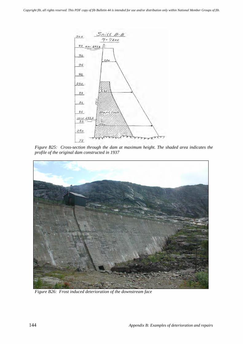
144 Appendix B: Examples of deterioration and repairs
Figure B25: Cross-section through the dam at maximum height. The shaded area indicates the profile of the original dam constructed in 1937
Figure B26: Frost induced deterioration of the downstream face
Copyright fib, all rights reserved. This PDF copy of fib Bulletin 44 is intended for use and/or distribution only within National Member Groups of fib.
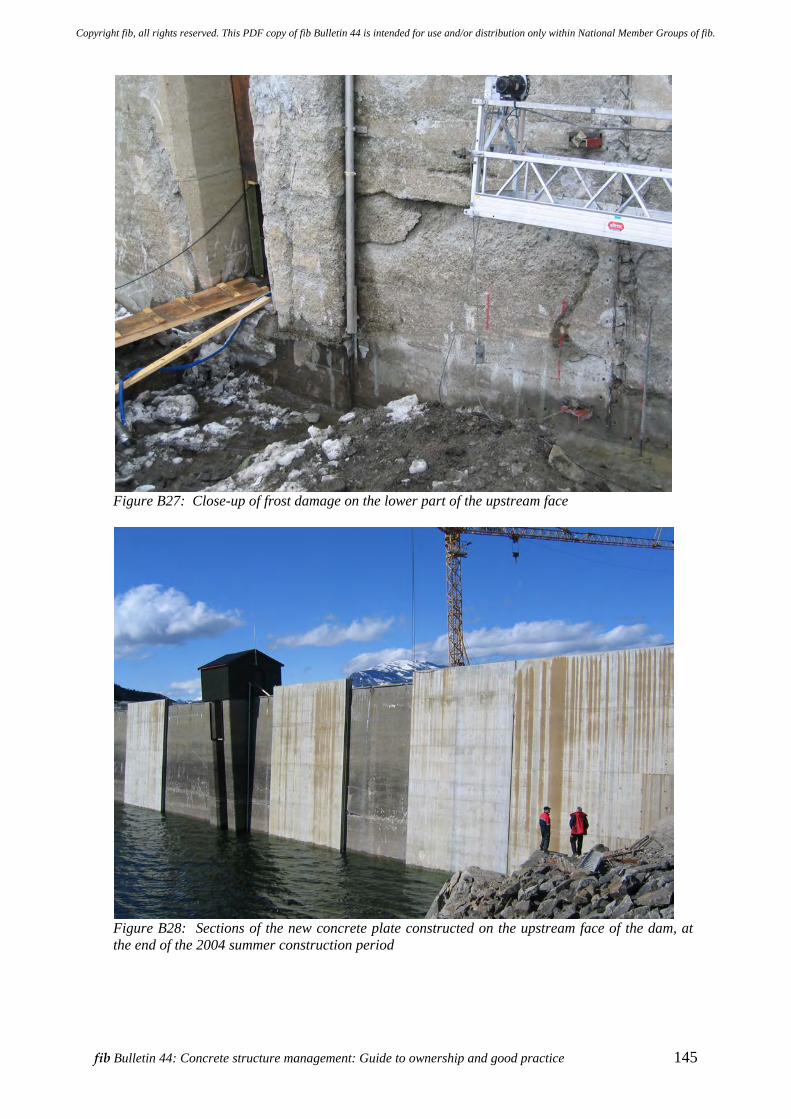
fib Bulletin 44: Concrete structure management: Guide to ownership and good practice 145
Figure B27: Close-up of frost damage on the lower part of the upstream face
Figure B28: Sections of the new concrete plate constructed on the upstream face of the dam, at the end of the 2004 summer construction period
Copyright fib, all rights reserved. This PDF copy of fib Bulletin 44 is intended for use and/or distribution only within National Member Groups of fib.

Copyright fib, all rights reserved. This PDF copy of fib Bulletin 44 is intended for use and/or distribution only within National Member Groups of fib.
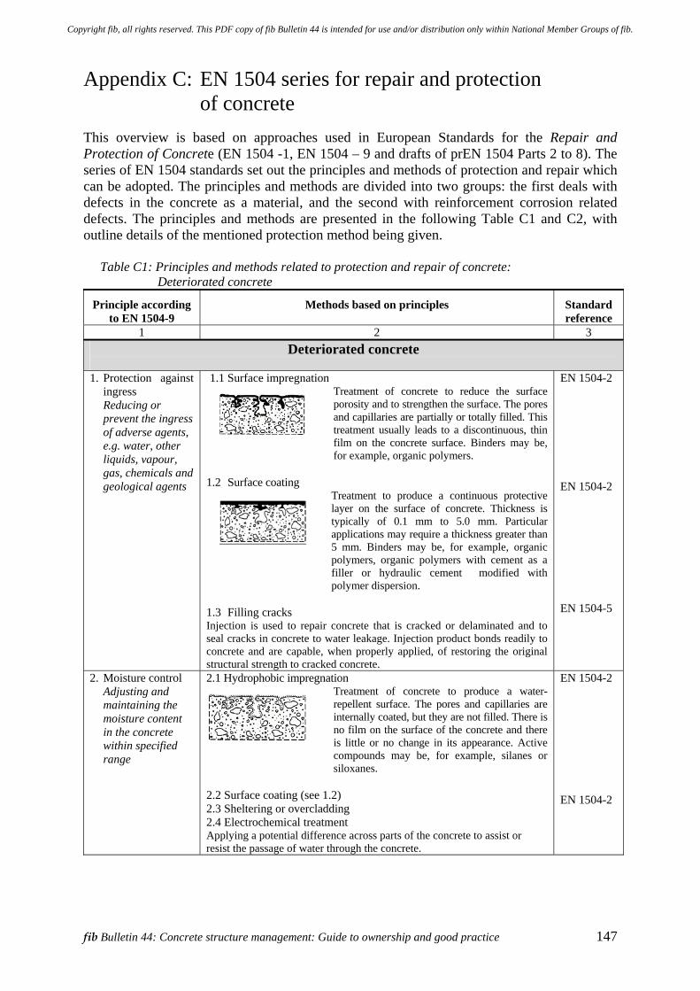
fib Bulletin 44: Concrete structure management: Guide to ownership and good practice 147
Appendix C: EN 1504 series for repair and protection of concrete
This overview is based on approaches used in European Standards for the Repair and Protection of Concrete (EN 1504 -1, EN 1504 – 9 and drafts of prEN 1504 Parts 2 to 8). The series of EN 1504 standards set out the principles and methods of protection and repair which can be adopted. The principles and methods are divided into two groups: the first deals with defects in the concrete as a material, and the second with reinforcement corrosion related defects. The principles and methods are presented in the following Table C1 and C2, with outline details of the mentioned protection method being given.
Table C1: Principles and methods related to protection and repair of concrete: Deteriorated concrete
Principle according to EN 1504-9
Methods based on principles Standard reference
1 2 3 Deteriorated concrete
1. Protection against
ingress Reducing or prevent the ingress of adverse agents, e.g. water, other liquids, vapour, gas, chemicals and geological agents
1.1 Surface impregnation Treatment of concrete to reduce the surface porosity and to strengthen the surface. The pores and capillaries are partially or totally filled. This treatment usually leads to a discontinuous, thin film on the concrete surface. Binders may be, for example, organic polymers.
1.2 Surface coating Treatment to produce a continuous protective layer on the surface of concrete. Thickness is typically of 0.1 mm to 5.0 mm. Particular applications may require a thickness greater than 5 mm. Binders may be, for example, organic polymers, organic polymers with cement as a filler or hydraulic cement modified with polymer dispersion.
1.3 Filling cracks Injection is used to repair concrete that is cracked or delaminated and to seal cracks in concrete to water leakage. Injection product bonds readily to concrete and are capable, when properly applied, of restoring the original structural strength to cracked concrete.
EN 1504-2 EN 1504-2 EN 1504-5
2. Moisture control Adjusting and maintaining the moisture content in the concrete within specified range
2.1 Hydrophobic impregnation Treatment of concrete to produce a water-repellent surface. The pores and capillaries are internally coated, but they are not filled. There is no film on the surface of the concrete and there is little or no change in its appearance. Active compounds may be, for example, silanes or siloxanes.
2.2 Surface coating (see 1.2) 2.3 Sheltering or overcladding 2.4 Electrochemical treatment Applying a potential difference across parts of the concrete to assist or resist the passage of water through the concrete.
EN 1504-2 EN 1504-2
Copyright fib, all rights reserved. This PDF copy of fib Bulletin 44 is intended for use and/or distribution only within National Member Groups of fib.
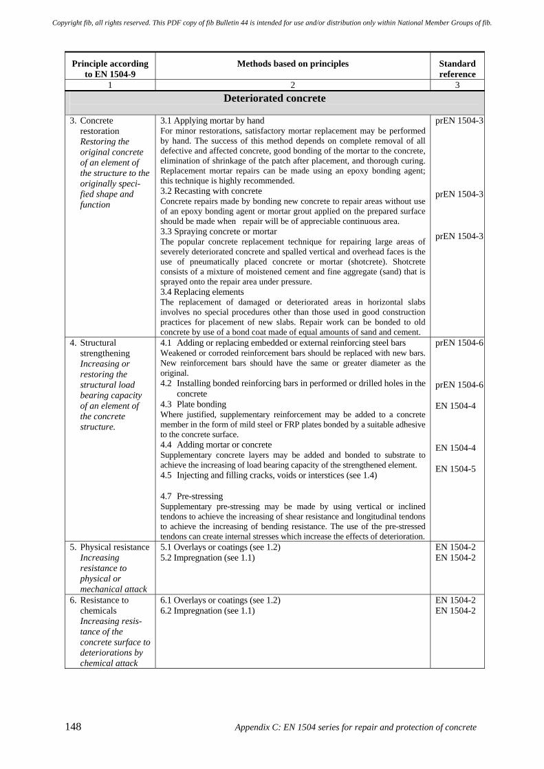
148 Appendix C: EN 1504 series for repair and protection of concrete
Principle according to EN 1504-9
Methods based on principles Standard reference
1 2 3 Deteriorated concrete
3. Concrete
restoration Restoring the original concrete of an element of the structure to the originally speci-fied shape and function
3.1 Applying mortar by hand For minor restorations, satisfactory mortar replacement may be performed by hand. The success of this method depends on complete removal of all defective and affected concrete, good bonding of the mortar to the concrete, elimination of shrinkage of the patch after placement, and thorough curing. Replacement mortar repairs can be made using an epoxy bonding agent; this technique is highly recommended. 3.2 Recasting with concrete Concrete repairs made by bonding new concrete to repair areas without use of an epoxy bonding agent or mortar grout applied on the prepared surface should be made when repair will be of appreciable continuous area. 3.3 Spraying concrete or mortar The popular concrete replacement technique for repairing large areas of severely deteriorated concrete and spalled vertical and overhead faces is the use of pneumatically placed concrete or mortar (shotcrete). Shotcrete consists of a mixture of moistened cement and fine aggregate (sand) that is sprayed onto the repair area under pressure. 3.4 Replacing elements The replacement of damaged or deteriorated areas in horizontal slabs involves no special procedures other than those used in good construction practices for placement of new slabs. Repair work can be bonded to old concrete by use of a bond coat made of equal amounts of sand and cement.
prEN 1504-3 prEN 1504-3 prEN 1504-3
4. Structural strengthening Increasing or restoring the structural load bearing capacity of an element of the concrete structure.
4.1 Adding or replacing embedded or external reinforcing steel bars Weakened or corroded reinforcement bars should be replaced with new bars. New reinforcement bars should have the same or greater diameter as the original. 4.2 Installing bonded reinforcing bars in performed or drilled holes in the
concrete 4.3 Plate bonding Where justified, supplementary reinforcement may be added to a concrete member in the form of mild steel or FRP plates bonded by a suitable adhesive to the concrete surface. 4.4 Adding mortar or concrete Supplementary concrete layers may be added and bonded to substrate to achieve the increasing of load bearing capacity of the strengthened element. 4.5 Injecting and filling cracks, voids or interstices (see 1.4) 4.7 Pre-stressing Supplementary pre-stressing may be made by using vertical or inclined tendons to achieve the increasing of shear resistance and longitudinal tendons to achieve the increasing of bending resistance. The use of the pre-stressed tendons can create internal stresses which increase the effects of deterioration.
prEN 1504-6 prEN 1504-6 EN 1504-4 EN 1504-4 EN 1504-5
5. Physical resistance Increasing resistance to physical or mechanical attack
5.1 Overlays or coatings (see 1.2) 5.2 Impregnation (see 1.1)
EN 1504-2 EN 1504-2
6. Resistance to chemicals Increasing resis-tance of the concrete surface to deteriorations by chemical attack
6.1 Overlays or coatings (see 1.2) 6.2 Impregnation (see 1.1)
EN 1504-2 EN 1504-2
Copyright fib, all rights reserved. This PDF copy of fib Bulletin 44 is intended for use and/or distribution only within National Member Groups of fib.
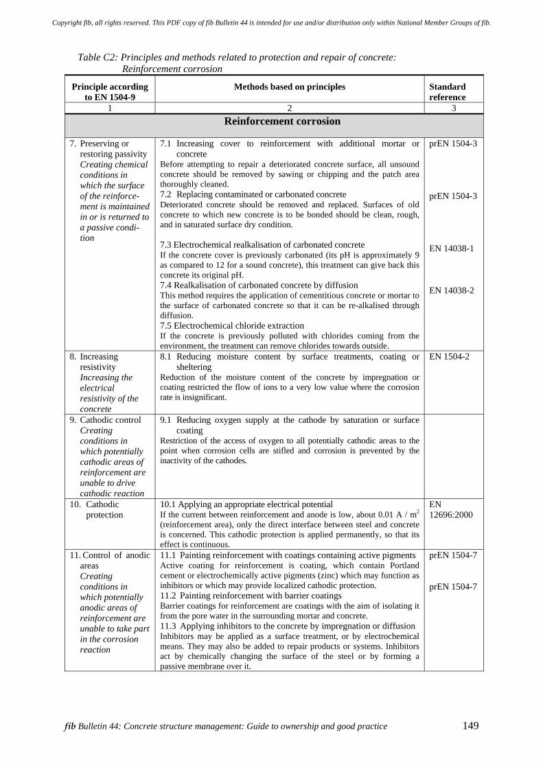
fib Bulletin 44: Concrete structure management: Guide to ownership and good practice 149
Table C2: Principles and methods related to protection and repair of concrete: Reinforcement corrosion
Principle according to EN 1504-9
Methods based on principles Standard reference
1 2 3 Reinforcement corrosion
7. Preserving or
restoring passivity Creating chemical conditions in which the surface of the reinforce-ment is maintained in or is returned to a passive condi-tion
7.1 Increasing cover to reinforcement with additional mortar or concrete
Before attempting to repair a deteriorated concrete surface, all unsound concrete should be removed by sawing or chipping and the patch area thoroughly cleaned. 7.2 Replacing contaminated or carbonated concrete Deteriorated concrete should be removed and replaced. Surfaces of old concrete to which new concrete is to be bonded should be clean, rough, and in saturated surface dry condition. 7.3 Electrochemical realkalisation of carbonated concrete If the concrete cover is previously carbonated (its pH is approximately 9 as compared to 12 for a sound concrete), this treatment can give back this concrete its original pH. 7.4 Realkalisation of carbonated concrete by diffusion This method requires the application of cementitious concrete or mortar to the surface of carbonated concrete so that it can be re-alkalised through diffusion. 7.5 Electrochemical chloride extraction If the concrete is previously polluted with chlorides coming from the environment, the treatment can remove chlorides towards outside.
prEN 1504-3 prEN 1504-3 EN 14038-1 EN 14038-2
8. Increasing resistivity Increasing the electrical resistivity of the concrete
8.1 Reducing moisture content by surface treatments, coating or sheltering
Reduction of the moisture content of the concrete by impregnation or coating restricted the flow of ions to a very low value where the corrosion rate is insignificant.
EN 1504-2
9. Cathodic control Creating conditions in which potentially cathodic areas of reinforcement are unable to drive cathodic reaction
9.1 Reducing oxygen supply at the cathode by saturation or surface coating
Restriction of the access of oxygen to all potentially cathodic areas to the point when corrosion cells are stifled and corrosion is prevented by the inactivity of the cathodes.
10. Cathodic protection
10.1 Applying an appropriate electrical potential If the current between reinforcement and anode is low, about 0.01 A / m2 (reinforcement area), only the direct interface between steel and concrete is concerned. This cathodic protection is applied permanently, so that its effect is continuous.
EN 12696:2000
11. Control of anodic areas Creating conditions in which potentially anodic areas of reinforcement are unable to take part in the corrosion reaction
11.1 Painting reinforcement with coatings containing active pigments Active coating for reinforcement is coating, which contain Portland cement or electrochemically active pigments (zinc) which may function as inhibitors or which may provide localized cathodic protection. 11.2 Painting reinforcement with barrier coatings Barrier coatings for reinforcement are coatings with the aim of isolating it from the pore water in the surrounding mortar and concrete. 11.3 Applying inhibitors to the concrete by impregnation or diffusion Inhibitors may be applied as a surface treatment, or by electrochemical means. They may also be added to repair products or systems. Inhibitors act by chemically changing the surface of the steel or by forming a passive membrane over it.
prEN 1504-7 prEN 1504-7
Copyright fib, all rights reserved. This PDF copy of fib Bulletin 44 is intended for use and/or distribution only within National Member Groups of fib.

Copyright fib, all rights reserved. This PDF copy of fib Bulletin 44 is intended for use and/or distribution only within National Member Groups of fib.
fib Bulletin 44: Concrete structure management: Guide to ownership and good practice 151
Appendix D: Standards for protection and repair of concrete D.1 Introduction
This section provides a brief overview of the standards for protection and repair of concrete adopted in a number of parts of the world. These are provided for Europe, Japan, Australia and the USA. These brief overviews facilitate some comparison of the various approaches adopted around the world. This section does not claim to be representative of all approaches employed, but hopefully it provides some insight and would enable the reader to pursue further enquiries should this be of interest.
D.2 European standards
Within the European Union the Construction Products Directive calls for standardisation of all products that are traded across member states in order to support a more open single market within Europe. Although this is proving to be a much more difficult and time consuming project than was ever initially anticipated, European Standards will become an increasingly important factor for the producers and users of all construction materials. Coupled with the public procurement rules within Europe, the use of European Standards will become mandatory for much of the construction industry. CEN (Comité Européen de Normalisation) has been working for many years to establish unified European standards for construction products and systems. It is making steady progress towards this goal. CEN TC104 SC8 is responsible for the development of European standards concerned with the protection and repair of concrete structures. The committee are working towards the overall introduction of EN 1504 which is entitled, “Products and systems for the protection and repair of concrete structures - Definitions, requirements, quality control, and evaluation of conformity”. This covers a number of aspects that specifically relate to the design and execution of repair and remediation treatments. The standard will fulfil a number of functions including: • Specify minimum performance levels so that a product can attain approval for sale in
Europe (the CE mark) for a given application. • To remove technical barriers to trade, with a repair product being deemed to satisfy
specification requirements by meeting the defined performance levels, whatever the country of manufacture.
• To provide reference to identification tests, by which a product may be sampled, checked and confirmed to be in accordance with a manufacturer's specification.
• To provide reference to relevant performance tests, by which the designer / specifier can select the most appropriate product for the repair.
• To provide standardised approaches for the design and execution of repairs to concrete structures.
The list of European standards related to the repair and protection of concrete and currently available as standards or are under development by CEN TC104 SC8 are presented in Table D1.
Copyright fib, all rights reserved. This PDF copy of fib Bulletin 44 is intended for use and/or distribution only within National Member Groups of fib.
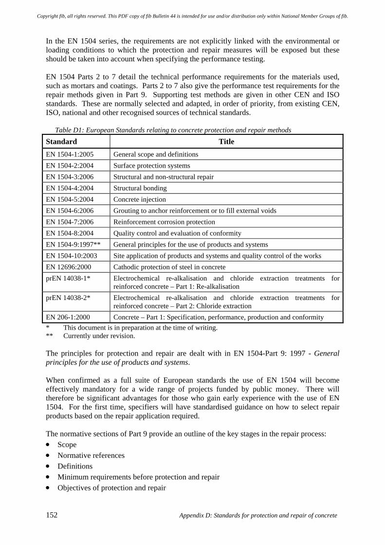
152 Appendix D: Standards for protection and repair of concrete
In the EN 1504 series, the requirements are not explicitly linked with the environmental or loading conditions to which the protection and repair measures will be exposed but these should be taken into account when specifying the performance testing. EN 1504 Parts 2 to 7 detail the technical performance requirements for the materials used, such as mortars and coatings. Parts 2 to 7 also give the performance test requirements for the repair methods given in Part 9. Supporting test methods are given in other CEN and ISO standards. These are normally selected and adapted, in order of priority, from existing CEN, ISO, national and other recognised sources of technical standards.
Table D1: European Standards relating to concrete protection and repair methods
Standard Title EN 1504-1:2005 General scope and definitions EN 1504-2:2004 Surface protection systems EN 1504-3:2006 Structural and non-structural repair EN 1504-4:2004 Structural bonding EN 1504-5:2004 Concrete injection EN 1504-6:2006 Grouting to anchor reinforcement or to fill external voids EN 1504-7:2006 Reinforcement corrosion protection EN 1504-8:2004 Quality control and evaluation of conformity EN 1504-9:1997** General principles for the use of products and systems EN 1504-10:2003 Site application of products and systems and quality control of the works EN 12696:2000 Cathodic protection of steel in concrete prEN 14038-1* Electrochemical re-alkalisation and chloride extraction treatments for
reinforced concrete – Part 1: Re-alkalisation prEN 14038-2* Electrochemical re-alkalisation and chloride extraction treatments for
reinforced concrete – Part 2: Chloride extraction EN 206-1:2000 Concrete – Part 1: Specification, performance, production and conformity * This document is in preparation at the time of writing. ** Currently under revision. The principles for protection and repair are dealt with in EN 1504-Part 9: 1997 - General principles for the use of products and systems. When confirmed as a full suite of European standards the use of EN 1504 will become effectively mandatory for a wide range of projects funded by public money. There will therefore be significant advantages for those who gain early experience with the use of EN 1504. For the first time, specifiers will have standardised guidance on how to select repair products based on the repair application required. The normative sections of Part 9 provide an outline of the key stages in the repair process: • Scope • Normative references • Definitions • Minimum requirements before protection and repair • Objectives of protection and repair
Copyright fib, all rights reserved. This PDF copy of fib Bulletin 44 is intended for use and/or distribution only within National Member Groups of fib.
fib Bulletin 44: Concrete structure management: Guide to ownership and good practice 153
• Basis for the choice of products and systems • Properties of products and systems required for compliance with the principle of
protection and repair • Maintenance following completion of protection or repair • Health, safety and the environment. The proposed selection strategy is presented in Figure 10 in the main report text. Part 9 provides notes for guidance regarding the methods included but does not exclude the use of other methods not mentioned. Specific applications that are excluded from the standard are: • structures damaged by fire, • any purpose other than protection or repair of concrete, and • defects of existing post-tensioned systems. However, the general principles can still be applied to such applications. Two informative annexes are included in the standard. Annex A of Part 9 of EN 1504 comprises a table that lists the properties of products and systems required for a variety of uses; all intended uses (AIU) and certain intended uses (CIU). Annex B of Part 9 of EN 1504 provides guidance and background information on the normative text. Minimum requirements for assessment of defects and their causes are given but Part 9 clearly states that it is not intended to be a guide for inspecting and assessing the condition of concrete structures. In the standard the strategic options for maintenance and repair that are listed range from doing nothing to complete demolition of the structure. When selecting an appropriate strategy a number of factors have to be considered such as, the cost of alternative protection and repair options, future maintenance and repair cycles, and the required future functionality of the structure.
D.3 Japanese standards
Table D2 lists the Japanese standards relating to concrete protection and repair methods. The first Japanese standard was “Practical Guideline for Corrosion Protection of Coastal Concrete Structures”, issued by the Japan Concrete Institute (JCI) in 1983. This guideline specifies two types of corrosion protection as follows: First type of corrosion protection: • Appropriate concrete cover
• Allowable crack width • Concrete quality
Second type of corrosion protection: • Epoxy-coated reinforcing steel bar • Cathodic protection • Formwork for corrosion protection
Copyright fib, all rights reserved. This PDF copy of fib Bulletin 44 is intended for use and/or distribution only within National Member Groups of fib.
154 Appendix D: Standards for protection and repair of concrete
The Japan Society of Civil Engineers (JSCE) issued its first guideline relating to protection and repair of concrete structures, “Guidelines for Retrofit of Concrete Structures - Draft-“ in 1999. The guidelines were prepared for structural repair, especially with external bonding, wrapping (or jacketing), over / under-laying and external prestressing. The repair materials covered in the guidelines are cementitious materials, steel and fibre reinforced plastics (FRP). The guidelines utilise performance-based concepts. JSCE later presented “Guideline on Upgrading of Concrete Structures with FRP Sheet”, which is concerned with structural repair using FRP sheet external bonding and wrapping. The guideline also shows that FRP sheet can be regarded as a layer to shield the structure from penetration by aggressive species. “Recommendation for Design and Construction of Electrochemical Corrosion Control Method - Draft” was issued by JSCE and describes electrochemical repair methods, together with associated investigation manuals and monitoring technology for corrosion protection for the following:
• Cathodic protection • Chloride extraction • Re-alkalization • Electro-deposition
JSCE’s “Standard Specifications for Concrete Structures – Maintenance” is intended to provide an overview on how to maintain concrete structures and includes standard maintenance methods. It takes account of various deterioration factors including carbonation, salt attack, frost attack, chemical attack, alkali aggregate reaction and fatigue. The Architectural Institute of Japan (AIJ) has presented the following standards for buildings:
• Recommendation for Practice of Survey, Diagnosis and Repair for Deterioration of Reinforced Concrete Structures
• Principal Guide for Refurbishment of Buildings The most recent standard is “Practical Guideline for Investigation, Repair and Strengthening of Cracked Concrete Structures” issued by JCI in 2003. This guideline addresses almost every issue required to protect and repair cracked concrete structures; namely investigation, assessment of cause, judgment on whether remedial action has to be taken or not, repair and strengthening measures. JSCE’s other relating documents are “Recommendation for Design and Construction of Concrete Structures Using Epoxy-Coated Reinforcing Steel Bars – Revised Edition” issued in 2003 (First edition was printed in 1986) and “Standard test methods for measurement of diffusion coefficient of chloride ions in concrete”, due for issue in 2004. There are several standard testing methods, specified as Japanese Industrial Standards (JIS) relating to concrete protection and repair methods. They address testing methods for measurement of carbonation depth, accelerating carbonation, and chloride ion contents (see Table D2).
Copyright fib, all rights reserved. This PDF copy of fib Bulletin 44 is intended for use and/or distribution only within National Member Groups of fib.
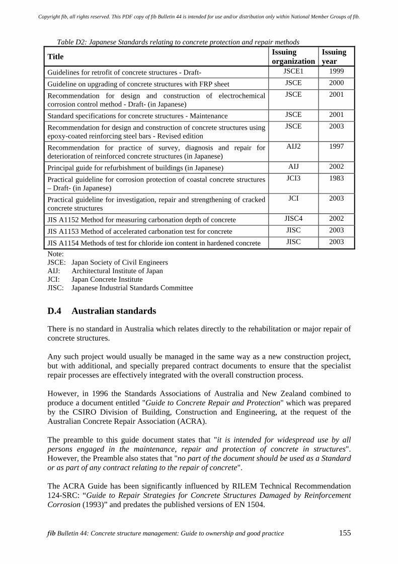
fib Bulletin 44: Concrete structure management: Guide to ownership and good practice 155
Table D2: Japanese Standards relating to concrete protection and repair methods
Title Issuing organization
Issuing year
Guidelines for retrofit of concrete structures - Draft- JSCE1 1999
Guideline on upgrading of concrete structures with FRP sheet JSCE 2000
Recommendation for design and construction of electrochemical corrosion control method - Draft- (in Japanese)
JSCE 2001
Standard specifications for concrete structures - Maintenance JSCE 2001
Recommendation for design and construction of concrete structures using epoxy-coated reinforcing steel bars - Revised edition
JSCE 2003
Recommendation for practice of survey, diagnosis and repair for deterioration of reinforced concrete structures (in Japanese)
AIJ2 1997
Principal guide for refurbishment of buildings (in Japanese) AIJ 2002
Practical guideline for corrosion protection of coastal concrete structures – Draft- (in Japanese)
JCI3 1983
Practical guideline for investigation, repair and strengthening of cracked concrete structures
JCI 2003
JIS A1152 Method for measuring carbonation depth of concrete JISC4 2002
JIS A1153 Method of accelerated carbonation test for concrete JISC 2003
JIS A1154 Methods of test for chloride ion content in hardened concrete JISC 2003
Note: JSCE: Japan Society of Civil Engineers AIJ: Architectural Institute of Japan JCI: Japan Concrete Institute JISC: Japanese Industrial Standards Committee
D.4 Australian standards
There is no standard in Australia which relates directly to the rehabilitation or major repair of concrete structures. Any such project would usually be managed in the same way as a new construction project, but with additional, and specially prepared contract documents to ensure that the specialist repair processes are effectively integrated with the overall construction process. However, in 1996 the Standards Associations of Australia and New Zealand combined to produce a document entitled "Guide to Concrete Repair and Protection" which was prepared by the CSIRO Division of Building, Construction and Engineering, at the request of the Australian Concrete Repair Association (ACRA). The preamble to this guide document states that "it is intended for widespread use by all persons engaged in the maintenance, repair and protection of concrete in structures". However, the Preamble also states that "no part of the document should be used as a Standard or as part of any contract relating to the repair of concrete". The ACRA Guide has been significantly influenced by RILEM Technical Recommendation 124-SRC: “Guide to Repair Strategies for Concrete Structures Damaged by Reinforcement Corrosion (1993)” and predates the published versions of EN 1504.
Copyright fib, all rights reserved. This PDF copy of fib Bulletin 44 is intended for use and/or distribution only within National Member Groups of fib.
156 Appendix D: Standards for protection and repair of concrete
The ACRA Guide is well-produced, well-presented and reader / user-friendly. The level of technical discussion is suitable for both engineers and technicians. The Guide includes selected references from both European and American sources, but its various sections flow relatively seamlessly - and not as a patched-together collection of extracts from the reference documents. The chapter headings of the ACRA guide are:
1 Concrete properties 2 Causes of concrete deterioration 3 Formation and types of cracks 4 Inspection techniques 5 Protective and remedial systems 6 Repair practice 7 Case studies Appendix A:-Repair strategies for carbonation-induced corrosion Appendix B:-Strategies for chloride-induced corrosion Appendix C:-Strategies for crack repair
The following short extract is an example of the simple but effective way in which this Guide is written. (It is taken from a clause dealing with the application of quality assurance to concrete patch repair).
..."the patch repair process would be performed in accordance with the project specific work procedure (also known as a technical instruction). The work procedure may be a derivative from the concrete repair guidelines, technical specification, or based on experience of the company".
When defects are noted in the repair - or in the execution of the repair process - a formal report (known as a non-conformance report (NCR)) is completed, to identify the area of defective work and to provide a brief description of the defect's nature The purpose of the NCR is to provide identification / traceability of the defect, a record of the remedial action taken and formal verification / acceptance of such rework. By using this formal process, all relevant parties can provide input to the remedial action methodology and constructive contributions can be offered to prevent the same defect recurring. Preventing a recurrence of the same defect is the most important aspect, and may consist of a “Task Team" rewriting work procedures, technical specifications, etc, to reduce or eliminate the risk of future problems. With such introductory guidance at his disposal, a relatively inexperienced engineer should be well-placed to take up any required functions with respect to procedures, specifications, auditing of documents or site operations etc.
Copyright fib, all rights reserved. This PDF copy of fib Bulletin 44 is intended for use and/or distribution only within National Member Groups of fib.
fib Bulletin 44: Concrete structure management: Guide to ownership and good practice 157
D.5 US standards
Bridge maintenance in the US is largely dealt with on a reactive basis. In general this means that problems are fixed only after they become significant. There is little or no effort to prevent the problems or to use testing or monitoring in a proactive manner to try and predict when problems will occur. Individual states set their own priorities and approaches to these issues. It is suggested that one of the main reasons for this situation, like in so many parts of the world, is a scarcity of resources for maintenance and repair. With the large inventory of ageing bridges in the US it is difficult to find enough trained people to properly collect all the data required to run effective bridge management systems or to follow-up on previous repair / maintenance efforts to evaluate their effectiveness. Additionally the Highway Bridge Replacement / Rehabilitation Program (HBRRP) - the funding system used by the FHWA to allocate funds to the states - until recently could not be used for preventive maintenance. Previously under the HBRRP funds would only be made available when the sufficiency rating for a bridge fell below a certain level. Thus for bridges that were close to qualifying for replacement the HBRRP had the effect of discouraging owners from maintaining them to improve their condition because this type of action was not eligible for Federal funding. With all 50 states in the US independently implementing similar but different programs, consistency of approach and sharing of information has been limited. However the situation has now begun to improve. For example, Texas and a number of other states perform two main types of in-service inspection of bridges: • The Federally mandated NBI (safety) inspection is required to be performed every two
years. The nature of this inspection is the same in all 50 states and condition scores are determined on a 0-9 basis for the deck, superstructure and substructure. The element condition ratings are used to calculate the overall sufficiency rating (SR). With this system the magnitude or nature of the particular maintenance or repair problem cannot be determined. If a bridge has 50 columns and one column has a low score, the entire substructure will get a low score for all of this type of component. The review is somewhat subjective as the outcome is influenced by the persons doing the inspection.
• Routine maintenance inspections are performed every 6 months by maintenance personnel. These inspections focus on maintenance related items such as plugged joints, debris in drainage channels, impact damage, etc.
Further details can be found at: http://www.dot.state.tx.us/services/general_services/ manuals.htm Many of the states in the US are working to develop a Bridge Management Information System (BMIS). PONTIS software developed by AASHTO is the software of choice in most States. PONTIS collects similar data to the NBI inspections but it is more detailed and can give an idea of the magnitude of the particular maintenance or repair problem to be addressed. PONTIS indicates the % of elements in poor condition. It also tracks trends as the scores of more elements drop with time. It can be used to predict when maintenance is needed both for prevention or repair. A cost estimation module also provides an “estimated cost to cure” in terms of “present worth” dollars. As with most inspection techniques PONTIS is limited because it relies on visual inspections (subjective) and does not incorporate testing or monitoring data. In addition the uniqueness if each repair means that the historical cost data may not be representative of actual expenditure which will be incurred when the work is undertaken.
Copyright fib, all rights reserved. This PDF copy of fib Bulletin 44 is intended for use and/or distribution only within National Member Groups of fib.

Copyright fib, all rights reserved. This PDF copy of fib Bulletin 44 is intended for use and/or distribution only within National Member Groups of fib.
fib Bulletin 44: Concrete structure management: Guide to ownership and good practice 159
Appendix E: Risk assessment and management E.1 Introduction
In engineering situations the concept of risk is typically expressed by an equation in a format similar to the following: Risk (consequence / unit time) =
Frequency (event / unit time) * Magnitude (Consequence / event) [1] Issues of risk and its perception generally have a number of facets. One possible framework for grouping these was set out previously in Section 4.2, during the discussion about the responsibilities and liabilities owners may have. There are a number of additional considerations such as the possibility of latent defects, the mitigating effects of insurance and the level of risk which an organisation or society is prepared to accept. It would still be possible for these facets to be grouped under the broad headings of: • Engineering parameters concerning functionality • Economic and financial interests • Societal and cultural factors • Environmental issues Thus a diverse range of factors has to be brought into the evaluation and this generally involves some form of weighting being applied to the respective fields. This enables an overall value to be determined, thereby allowing comparison to be made of different situations or options for managing the risk(s).
E.2 Qualitative risk assessment
It may not be practical to make an explicit quantitative (numerical) evaluation of all the significant factors contributing to the risk environment. In these circumstances, a common approach is to use some form of risk matrix (frequency versus severity) concept. This provides a simpler basis to support aspects of the decision making needed for assessing or managing the structure concerned. The approach is essentially qualitative, with either high, medium and low ratings generally being given to the factors under consideration. Figure 4 illustrates one potential simplified risk matrix format. It may be necessary to employ a number of risk matrices to cover the range of risk issues to be considered. The following illustrates a possible qualitative approach to risk assessment and management. The categories of severity / consequence of a hazard are defined in Table E1 to provide a quantitative measure of the worst possible incident resulting from the hazardous situation, e.g. personal error, environmental incidents, design inadequacies, procedural deficiencies, and system, subsystem, or component failure or malfunction.
Copyright fib, all rights reserved. This PDF copy of fib Bulletin 44 is intended for use and/or distribution only within National Member Groups of fib.
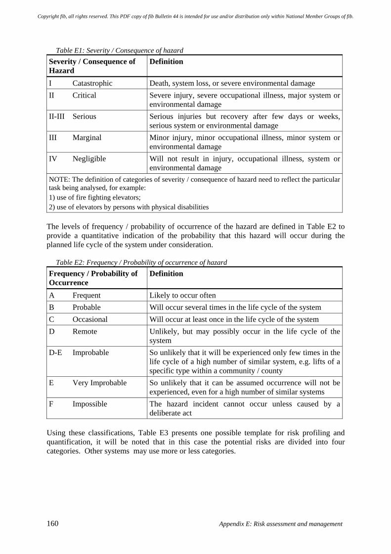
160 Appendix E: Risk assessment and management
Table E1: Severity / Consequence of hazard
Severity / Consequence of Hazard
Definition
I Catastrophic Death, system loss, or severe environmental damage II Critical Severe injury, severe occupational illness, major system or
environmental damage II-III Serious Serious injuries but recovery after few days or weeks,
serious system or environmental damage III Marginal Minor injury, minor occupational illness, minor system or
environmental damage IV Negligible Will not result in injury, occupational illness, system or
environmental damage NOTE: The definition of categories of severity / consequence of hazard need to reflect the particular task being analysed, for example: 1) use of fire fighting elevators; 2) use of elevators by persons with physical disabilities
The levels of frequency / probability of occurrence of the hazard are defined in Table E2 to provide a quantitative indication of the probability that this hazard will occur during the planned life cycle of the system under consideration.
Table E2: Frequency / Probability of occurrence of hazard Frequency / Probability of Occurrence
Definition
A Frequent Likely to occur often B Probable Will occur several times in the life cycle of the system C Occasional Will occur at least once in the life cycle of the system D Remote Unlikely, but may possibly occur in the life cycle of the
system D-E Improbable So unlikely that it will be experienced only few times in the
life cycle of a high number of similar system, e.g. lifts of a specific type within a community / county
E Very Improbable So unlikely that it can be assumed occurrence will not be experienced, even for a high number of similar systems
F Impossible The hazard incident cannot occur unless caused by a deliberate act
Using these classifications, Table E3 presents one possible template for risk profiling and quantification, it will be noted that in this case the potential risks are divided into four categories. Other systems may use more or less categories.
Copyright fib, all rights reserved. This PDF copy of fib Bulletin 44 is intended for use and/or distribution only within National Member Groups of fib.
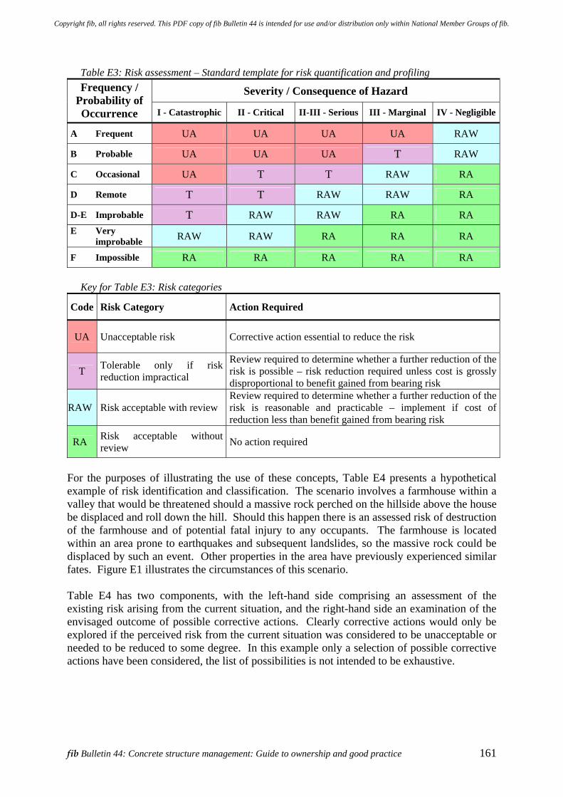
fib Bulletin 44: Concrete structure management: Guide to ownership and good practice 161
Table E3: Risk assessment – Standard template for risk quantification and profiling
Severity / Consequence of Hazard Frequency / Probability of Occurrence I - Catastrophic II - Critical II-III - Serious III - Marginal IV - Negligible
A Frequent UA UA UA UA RAW
B Probable UA UA UA T RAW
C Occasional UA T T RAW RA
D Remote T T RAW RAW RA
D-E Improbable T RAW RAW RA RA E Very
improbable RAW RAW RA RA RA
F Impossible RA RA RA RA RA
Key for Table E3: Risk categories
Code Risk Category Action Required
UA Unacceptable risk Corrective action essential to reduce the risk
T Tolerable only if risk reduction impractical
Review required to determine whether a further reduction of the risk is possible – risk reduction required unless cost is grossly disproportional to benefit gained from bearing risk
RAW Risk acceptable with review Review required to determine whether a further reduction of the risk is reasonable and practicable – implement if cost of reduction less than benefit gained from bearing risk
RA Risk acceptable without review No action required
For the purposes of illustrating the use of these concepts, Table E4 presents a hypothetical example of risk identification and classification. The scenario involves a farmhouse within a valley that would be threatened should a massive rock perched on the hillside above the house be displaced and roll down the hill. Should this happen there is an assessed risk of destruction of the farmhouse and of potential fatal injury to any occupants. The farmhouse is located within an area prone to earthquakes and subsequent landslides, so the massive rock could be displaced by such an event. Other properties in the area have previously experienced similar fates. Figure E1 illustrates the circumstances of this scenario. Table E4 has two components, with the left-hand side comprising an assessment of the existing risk arising from the current situation, and the right-hand side an examination of the envisaged outcome of possible corrective actions. Clearly corrective actions would only be explored if the perceived risk from the current situation was considered to be unacceptable or needed to be reduced to some degree. In this example only a selection of possible corrective actions have been considered, the list of possibilities is not intended to be exhaustive.
Copyright fib, all rights reserved. This PDF copy of fib Bulletin 44 is intended for use and/or distribution only within National Member Groups of fib.
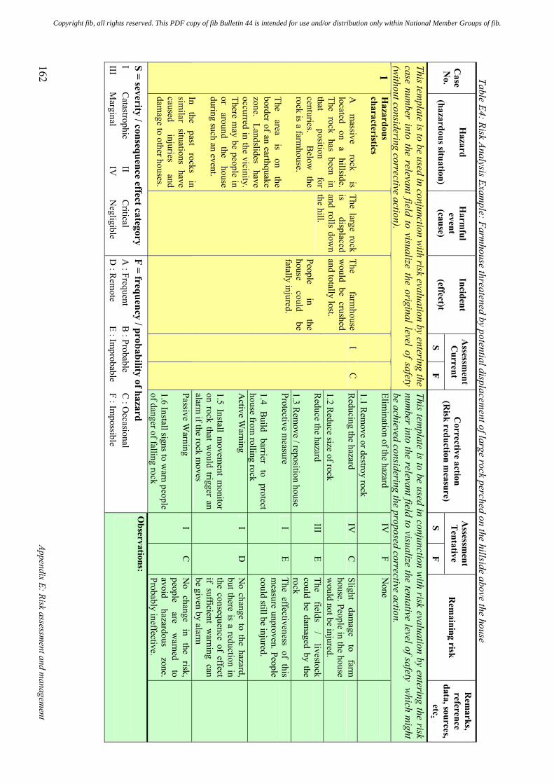
162 Appendix E: Risk assessm
ent and managem
ent
Table E4: Risk Analysis Exam
ple: Farmhouse threatened by potential displacem
ent of large rock perched on the hillside above the house A
ssessment
Current
Assessm
ent Tentative
Case
No.
Hazard
(hazardous situation)
Harm
ful event
(cause)
Incident
(effect)t S
F
Corrective action
(Risk reduction m
easure) S
F
Rem
aining risk
Rem
arks, reference
data, sources, etc.
This template is to be used in conjunction w
ith risk evaluation by entering the case num
ber into the relevant field to visualize the original level of safety (w
ithout considering corrective action).
This template is to be used in conjunction w
ith risk evaluation by entering the risk num
ber into the relevant field to visualize the tentative level of safety which m
ight be achieved considering the proposed corrective action. Elim
ination of the hazard 1.1 R
emove or destroy rock
IV
F N
one
Reducing the hazard
1.2 Reduce size of rock
IV
C
Slight dam
age to
farm
house. People in the house w
ould not be injured.
Reduce the hazard
1.3 Rem
ove / reposition house
III E
The fields
/ livestock
could be damaged by the
rock
Protective measure
1.4 B
uild barrier
to protect
house from rolling rock
I E
The effectiveness of this m
easure unproven. People could still be injured.
Active W
arning 1.5 Install m
ovement m
onitor on rock that w
ould trigger an alarm
if the rock moves
I D
N
o change to the hazard, but there is a reduction in the consequence of effect if sufficient w
arning can be given by alarm
1
Hazardous
characteristics A
m
assive rock
is located
on a
hillside. The rock has been in that
position for
centuries.
Below
the
rock is a farmhouse.
The area
is on
the border of an earthquake zone.
Landslides have
occurred in the vicinity. There m
ay be people in or
around the
house during such an event. In
the past
rocks in
similar situations have
caused injuries
and dam
age to other houses.
The large rock is
displaced and rolls dow
n the hill.
The farm
house w
ould be crushed and totally lost. People
in the
house could
be fatally injured.
I
C
Passive Warning
1.6 Install signs to warn people
of danger of falling rock
I C
N
o change
in the
risk, people
are w
arned to
avoid hazardous
zone. Probably ineffective.
S = severity / consequence effect category I
Catastrophic
II C
ritical III
Marginal
IV
N
egligible
F = frequency / probability of hazard A
: Frequent B
: Probable C
: Occasional
D : R
emote
E : Improbable
F : Impossible
Observations:
Copyright fib, all rights reserved. This PDF copy of fib Bulletin 44 is intended for use and/or distribution only within National Member Groups of fib.
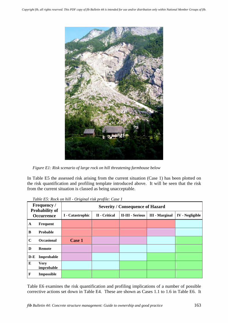
fib Bulletin 44: Concrete structure management: Guide to ownership and good practice 163
Figure E1: Risk scenario of large rock on hill threatening farmhouse below In Table E5 the assessed risk arising from the current situation (Case 1) has been plotted on the risk quantification and profiling template introduced above. It will be seen that the risk from the current situation is classed as being unacceptable.
Table E5: Rock on hill - Original risk profile: Case 1
Severity / Consequence of Hazard Frequency / Probability of Occurrence I - Catastrophic II - Critical II-III - Serious III - Marginal IV - Negligible
A Frequent
B Probable
C Occasional Case 1
D Remote
D-E Improbable E Very
improbable
F Impossible Table E6 examines the risk quantification and profiling implications of a number of possible corrective actions set down in Table E4. These are shown as Cases 1.1 to 1.6 in Table E6. It
Copyright fib, all rights reserved. This PDF copy of fib Bulletin 44 is intended for use and/or distribution only within National Member Groups of fib.
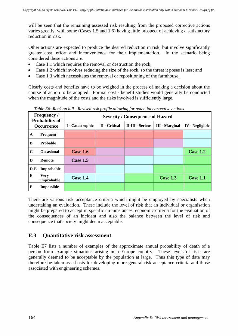
164 Appendix E: Risk assessment and management
will be seen that the remaining assessed risk resulting from the proposed corrective actions varies greatly, with some (Cases 1.5 and 1.6) having little prospect of achieving a satisfactory reduction in risk. Other actions are expected to produce the desired reduction in risk, but involve significantly greater cost, effort and inconvenience for their implementation. In the scenario being considered these actions are: • Case 1.1 which requires the removal or destruction the rock; • Case 1.2 which involves reducing the size of the rock, so the threat it poses is less; and • Case 1.3 which necessitates the removal or repositioning of the farmhouse. Clearly costs and benefits have to be weighed in the process of making a decision about the course of action to be adopted. Formal cost - benefit studies would generally be conducted when the magnitude of the costs and the risks involved is sufficiently large.
Table E6: Rock on hill - Revised risk profile allowing for potential corrective actions
Severity / Consequence of Hazard Frequency / Probability of Occurrence I - Catastrophic II - Critical II-III - Serious III - Marginal IV - Negligible
A Frequent
B Probable
C Occasional Case 1.6 Case 1.2
D Remote Case 1.5
D-E Improbable E Very
improbable Case 1.4 Case 1.3 Case 1.1
F Impossible There are various risk acceptance criteria which might be employed by specialists when undertaking an evaluation. These include the level of risk that an individual or organisation might be prepared to accept in specific circumstances, economic criteria for the evaluation of the consequences of an incident and also the balance between the level of risk and consequence that society might deem acceptable.
E.3 Quantitative risk assessment
Table E7 lists a number of examples of the approximate annual probability of death of a person from example situations arising in a Europe country. These levels of risks are generally deemed to be acceptable by the population at large. Thus this type of data may therefore be taken as a basis for developing more general risk acceptance criteria and those associated with engineering schemes.
Copyright fib, all rights reserved. This PDF copy of fib Bulletin 44 is intended for use and/or distribution only within National Member Groups of fib.
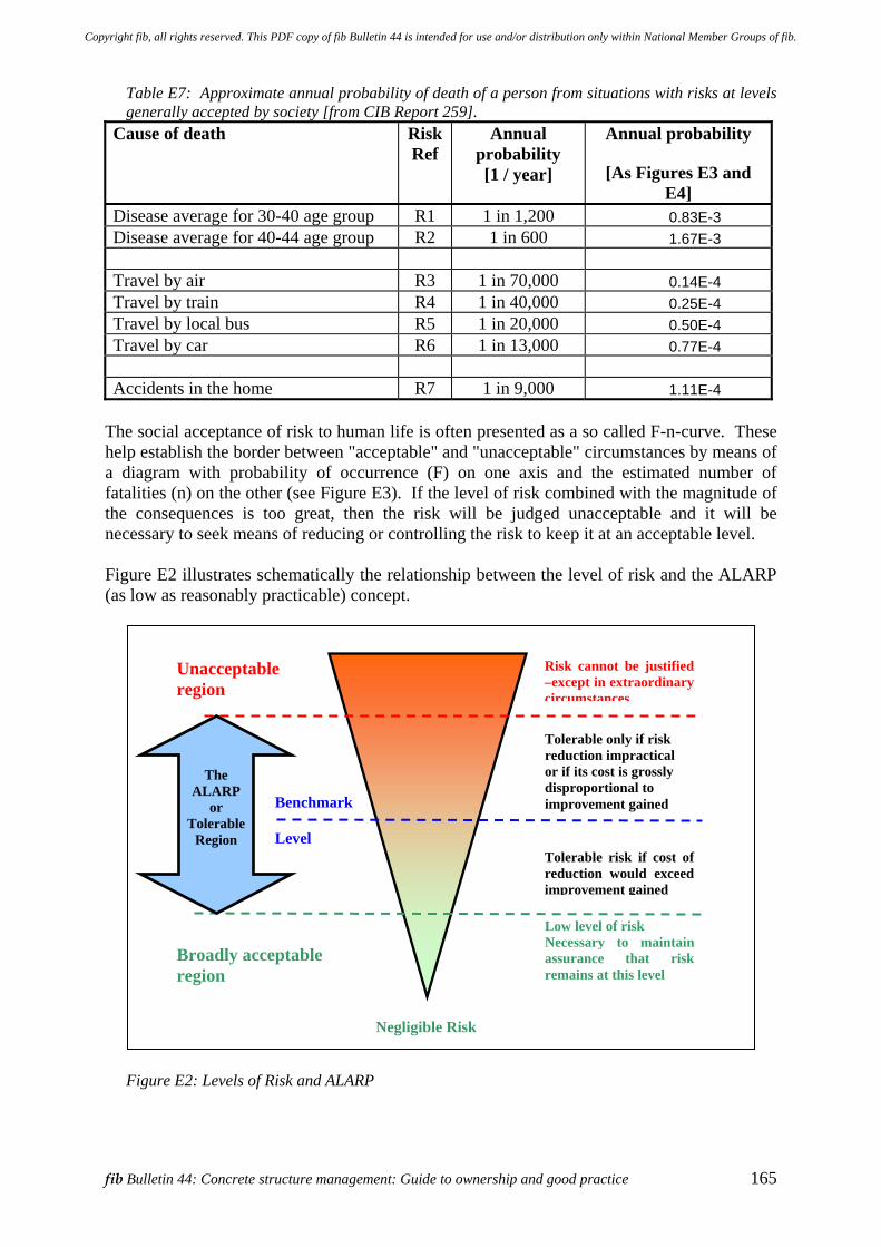
fib Bulletin 44: Concrete structure management: Guide to ownership and good practice 165
Table E7: Approximate annual probability of death of a person from situations with risks at levels generally accepted by society [from CIB Report 259].
Cause of death
Risk Ref
Annual probability [1 / year]
Annual probability
[As Figures E3 and E4]
Disease average for 30-40 age group R1 1 in 1,200 0.83E-3 Disease average for 40-44 age group R2 1 in 600 1.67E-3 Travel by air R3 1 in 70,000 0.14E-4 Travel by train R4 1 in 40,000 0.25E-4 Travel by local bus R5 1 in 20,000 0.50E-4 Travel by car R6 1 in 13,000 0.77E-4 Accidents in the home R7 1 in 9,000 1.11E-4
The social acceptance of risk to human life is often presented as a so called F-n-curve. These help establish the border between "acceptable" and "unacceptable" circumstances by means of a diagram with probability of occurrence (F) on one axis and the estimated number of fatalities (n) on the other (see Figure E3). If the level of risk combined with the magnitude of the consequences is too great, then the risk will be judged unacceptable and it will be necessary to seek means of reducing or controlling the risk to keep it at an acceptable level. Figure E2 illustrates schematically the relationship between the level of risk and the ALARP (as low as reasonably practicable) concept.
Figure E2: Levels of Risk and ALARP
Unacceptable region
Broadly acceptable region
Risk cannot be justified –except in extraordinary circumstances
Low level of risk Necessary to maintain assurance that risk remains at this level
Tolerable risk if cost of reduction would exceed improvement gained
Tolerable only if risk reduction impractical or if its cost is grossly disproportional to improvement gained
The
ALARP or
Tolerable Region
Benchmark Level
Negligible Risk
Copyright fib, all rights reserved. This PDF copy of fib Bulletin 44 is intended for use and/or distribution only within National Member Groups of fib.
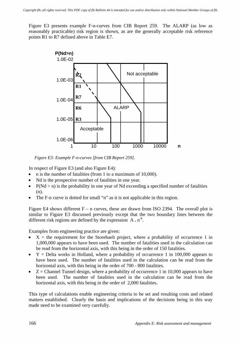
166 Appendix E: Risk assessment and management
Figure E3 presents example F-n-curves from CIB Report 259. The ALARP (as low as reasonably practicable) risk region is shown, as are the generally acceptable risk reference points R1 to R7 defined above in Table E7.
P(Nd>n) 1.0E-02
1.0E-03
1.0E-04
1.0E-05
1.0E-061 10 100 1000 10000 n
Not acceptable
ALARP
Acceptable
Figure E3: Example F-n-curves [from CIB Report 259].
In respect of Figure E3 (and also Figure E4): • n is the number of fatalities (from 1 to a maximum of 10,000). • Nd is the prospective number of fatalities in one year. • P(Nd > n) is the probability in one year of Nd exceeding a specified number of fatalities
(n). • The F-n curve is dotted for small “n” as it is not applicable in this region. Figure E4 shows different F – n curves, these are drawn from ISO 2394. The overall plot is similar to Figure E3 discussed previously except that the two boundary lines between the different risk regions are defined by the expression A . n-k. Examples from engineering practice are given: • X = the requirement for the Storebaelt project, where a probability of occurrence 1 in
1,000,000 appears to have been used. The number of fatalities used in the calculation can be read from the horizontal axis, with this being in the order of 150 fatalities.
• Y = Delta works in Holland, where a probability of occurrence 1 in 100,000 appears to have been used. The number of fatalities used in the calculation can be read from the horizontal axis, with this being in the order of 700 - 800 fatalities.
• Z = Channel Tunnel design, where a probability of occurrence 1 in 10,000 appears to have been used. The number of fatalities used in the calculation can be read from the horizontal axis, with this being in the order of 2,000 fatalities.
This type of calculations enable engineering criteria to be set and resulting costs and related matters established. Clearly the basis and implications of the decisions being in this way made need to be examined very carefully.
R7
R6 R3
R2 R1
Copyright fib, all rights reserved. This PDF copy of fib Bulletin 44 is intended for use and/or distribution only within National Member Groups of fib.
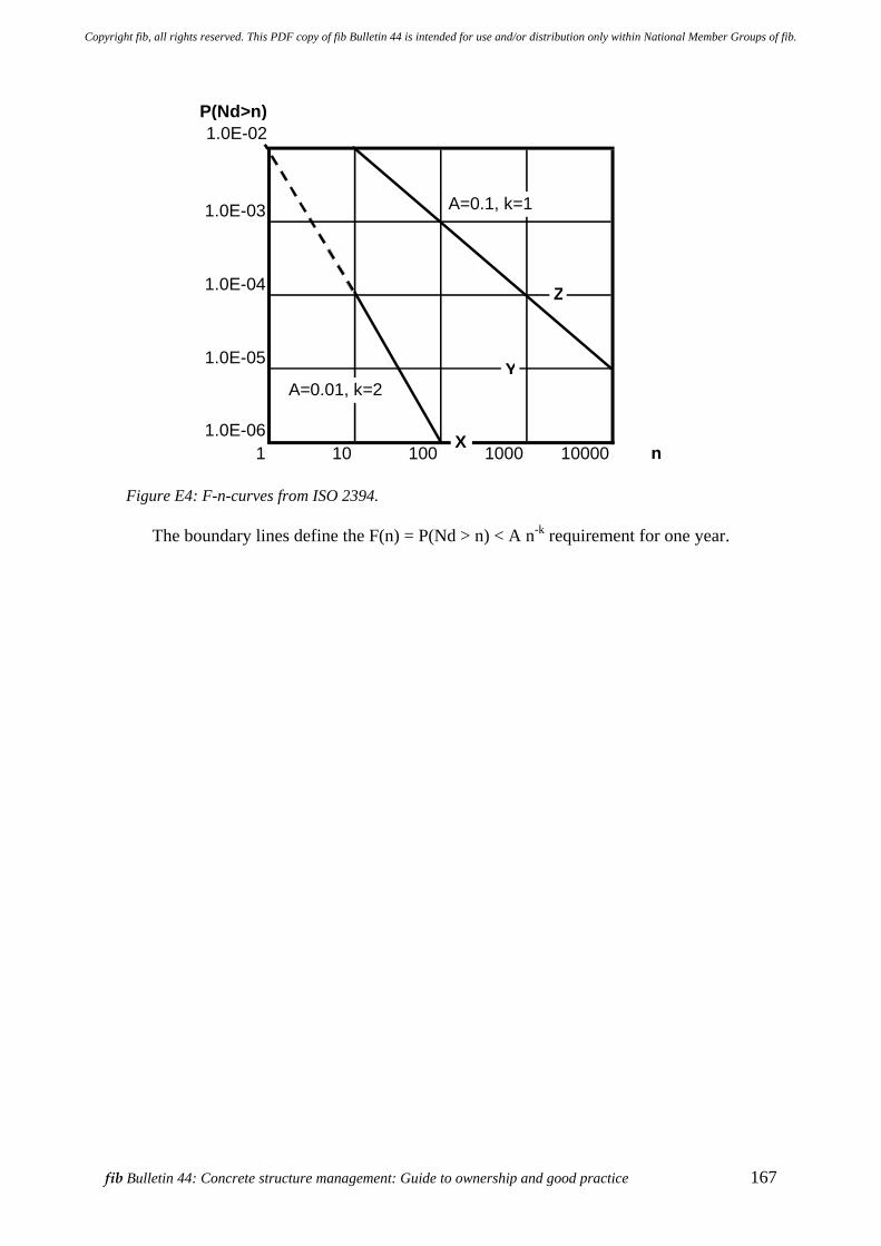
fib Bulletin 44: Concrete structure management: Guide to ownership and good practice 167
P(Nd>n) 1.0E-02
1.0E-03
1.0E-04
1.0E-05
1.0E-061 10 100 1000 10000 n
A=0.1, k=1
A=0.01, k=2
Z
Y
X
Figure E4: F-n-curves from ISO 2394.
The boundary lines define the F(n) = P(Nd > n) < A n-k requirement for one year.
Copyright fib, all rights reserved. This PDF copy of fib Bulletin 44 is intended for use and/or distribution only within National Member Groups of fib.

Copyright fib, all rights reserved. This PDF copy of fib Bulletin 44 is intended for use and/or distribution only within National Member Groups of fib.
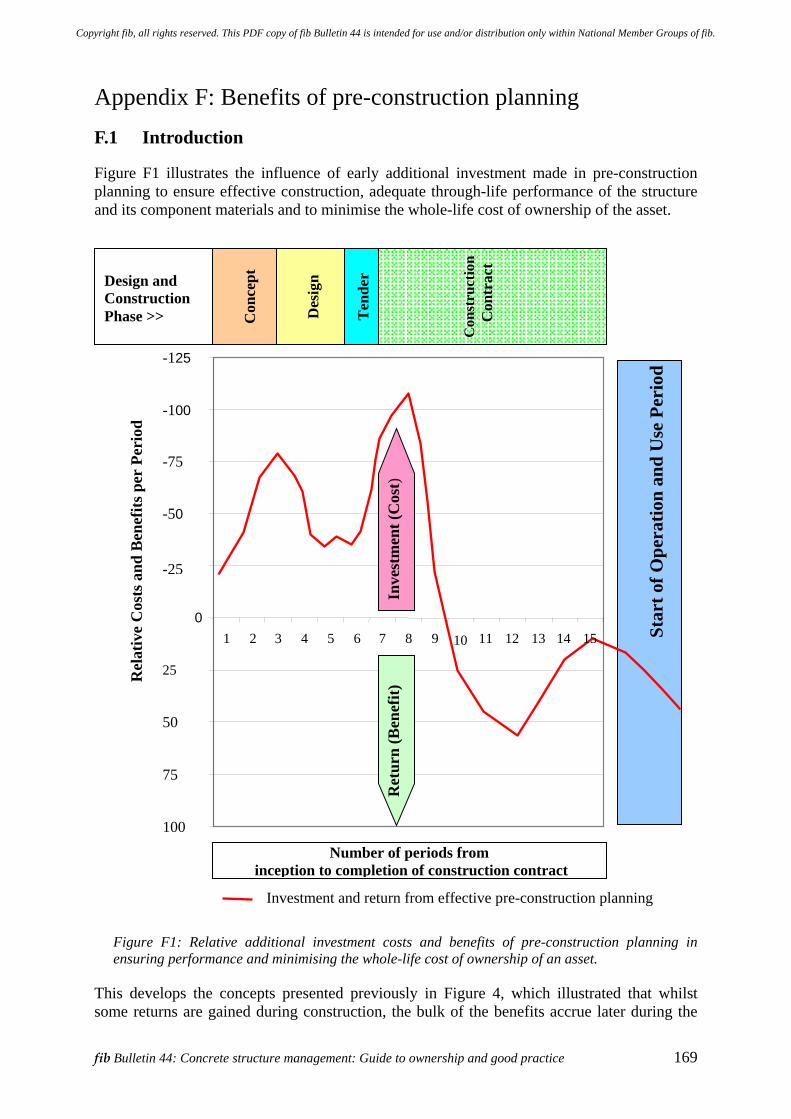
fib Bulletin 44: Concrete structure management: Guide to ownership and good practice 169
Appendix F: Benefits of pre-construction planning F.1 Introduction
Figure F1 illustrates the influence of early additional investment made in pre-construction planning to ensure effective construction, adequate through-life performance of the structure and its component materials and to minimise the whole-life cost of ownership of the asset.
Figure F1: Relative additional investment costs and benefits of pre-construction planning in ensuring performance and minimising the whole-life cost of ownership of an asset.
This develops the concepts presented previously in Figure 4, which illustrated that whilst some returns are gained during construction, the bulk of the benefits accrue later during the
St
art o
f Ope
ratio
n an
d U
se P
erio
d
100
75
50
25
0
-25
-50
-75
-100
-125
1 2 3 4 5 6 7 8 9 10 11 12 13 14 15
Number of periods from inception to completion of construction contract
Rel
ativ
e C
osts
and
Ben
efits
per
Per
iod
Investment and return from effective pre-construction planning
Design and Construction Phase >>
C
onst
ruct
ion
Con
trac
t
Ten
der
C
once
pt
D
esig
n
Inve
stm
ent (
Cos
t)
Ret
urn
(Ben
efit)
Copyright fib, all rights reserved. This PDF copy of fib Bulletin 44 is intended for use and/or distribution only within National Member Groups of fib.
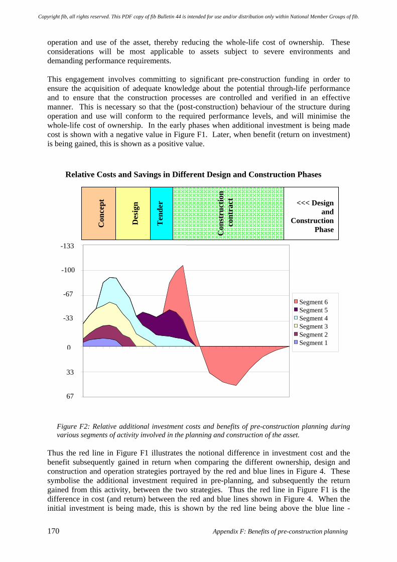
170 Appendix F: Benefits of pre-construction planning
operation and use of the asset, thereby reducing the whole-life cost of ownership. These considerations will be most applicable to assets subject to severe environments and demanding performance requirements. This engagement involves committing to significant pre-construction funding in order to ensure the acquisition of adequate knowledge about the potential through-life performance and to ensure that the construction processes are controlled and verified in an effective manner. This is necessary so that the (post-construction) behaviour of the structure during operation and use will conform to the required performance levels, and will minimise the whole-life cost of ownership. In the early phases when additional investment is being made cost is shown with a negative value in Figure F1. Later, when benefit (return on investment) is being gained, this is shown as a positive value.
Figure F2: Relative additional investment costs and benefits of pre-construction planning during various segments of activity involved in the planning and construction of the asset.
Thus the red line in Figure F1 illustrates the notional difference in investment cost and the benefit subsequently gained in return when comparing the different ownership, design and construction and operation strategies portrayed by the red and blue lines in Figure 4. These symbolise the additional investment required in pre-planning, and subsequently the return gained from this activity, between the two strategies. Thus the red line in Figure F1 is the difference in cost (and return) between the red and blue lines shown in Figure 4. When the initial investment is being made, this is shown by the red line being above the blue line -
Relative Costs and Savings in Different Design and Construction Phases
67
33
0
-33
-67
-100
-133
Segment 6 Segment 5 Segment 4 Segment 3 Segment 2 Segment 1
C
onst
ruct
ion
con
trac
t
Ten
der
C
once
pt
D
esig
n <<< Design and
Construction Phase
Copyright fib, all rights reserved. This PDF copy of fib Bulletin 44 is intended for use and/or distribution only within National Member Groups of fib.
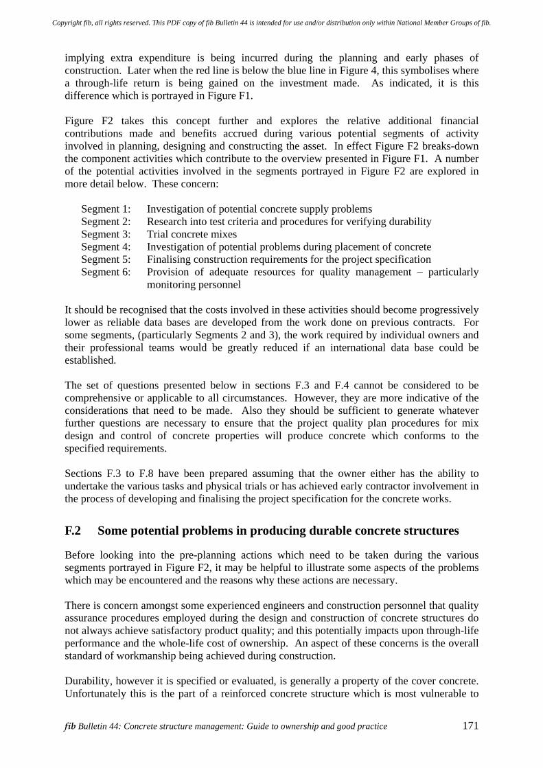
fib Bulletin 44: Concrete structure management: Guide to ownership and good practice 171
implying extra expenditure is being incurred during the planning and early phases of construction. Later when the red line is below the blue line in Figure 4, this symbolises where a through-life return is being gained on the investment made. As indicated, it is this difference which is portrayed in Figure F1. Figure F2 takes this concept further and explores the relative additional financial contributions made and benefits accrued during various potential segments of activity involved in planning, designing and constructing the asset. In effect Figure F2 breaks-down the component activities which contribute to the overview presented in Figure F1. A number of the potential activities involved in the segments portrayed in Figure F2 are explored in more detail below. These concern:
Segment 1: Investigation of potential concrete supply problems Segment 2: Research into test criteria and procedures for verifying durability Segment 3: Trial concrete mixes Segment 4: Investigation of potential problems during placement of concrete Segment 5: Finalising construction requirements for the project specification Segment 6: Provision of adequate resources for quality management – particularly
monitoring personnel It should be recognised that the costs involved in these activities should become progressively lower as reliable data bases are developed from the work done on previous contracts. For some segments, (particularly Segments 2 and 3), the work required by individual owners and their professional teams would be greatly reduced if an international data base could be established. The set of questions presented below in sections F.3 and F.4 cannot be considered to be comprehensive or applicable to all circumstances. However, they are more indicative of the considerations that need to be made. Also they should be sufficient to generate whatever further questions are necessary to ensure that the project quality plan procedures for mix design and control of concrete properties will produce concrete which conforms to the specified requirements. Sections F.3 to F.8 have been prepared assuming that the owner either has the ability to undertake the various tasks and physical trials or has achieved early contractor involvement in the process of developing and finalising the project specification for the concrete works.
F.2 Some potential problems in producing durable concrete structures
Before looking into the pre-planning actions which need to be taken during the various segments portrayed in Figure F2, it may be helpful to illustrate some aspects of the problems which may be encountered and the reasons why these actions are necessary. There is concern amongst some experienced engineers and construction personnel that quality assurance procedures employed during the design and construction of concrete structures do not always achieve satisfactory product quality; and this potentially impacts upon through-life performance and the whole-life cost of ownership. An aspect of these concerns is the overall standard of workmanship being achieved during construction. Durability, however it is specified or evaluated, is generally a property of the cover concrete. Unfortunately this is the part of a reinforced concrete structure which is most vulnerable to
Copyright fib, all rights reserved. This PDF copy of fib Bulletin 44 is intended for use and/or distribution only within National Member Groups of fib.
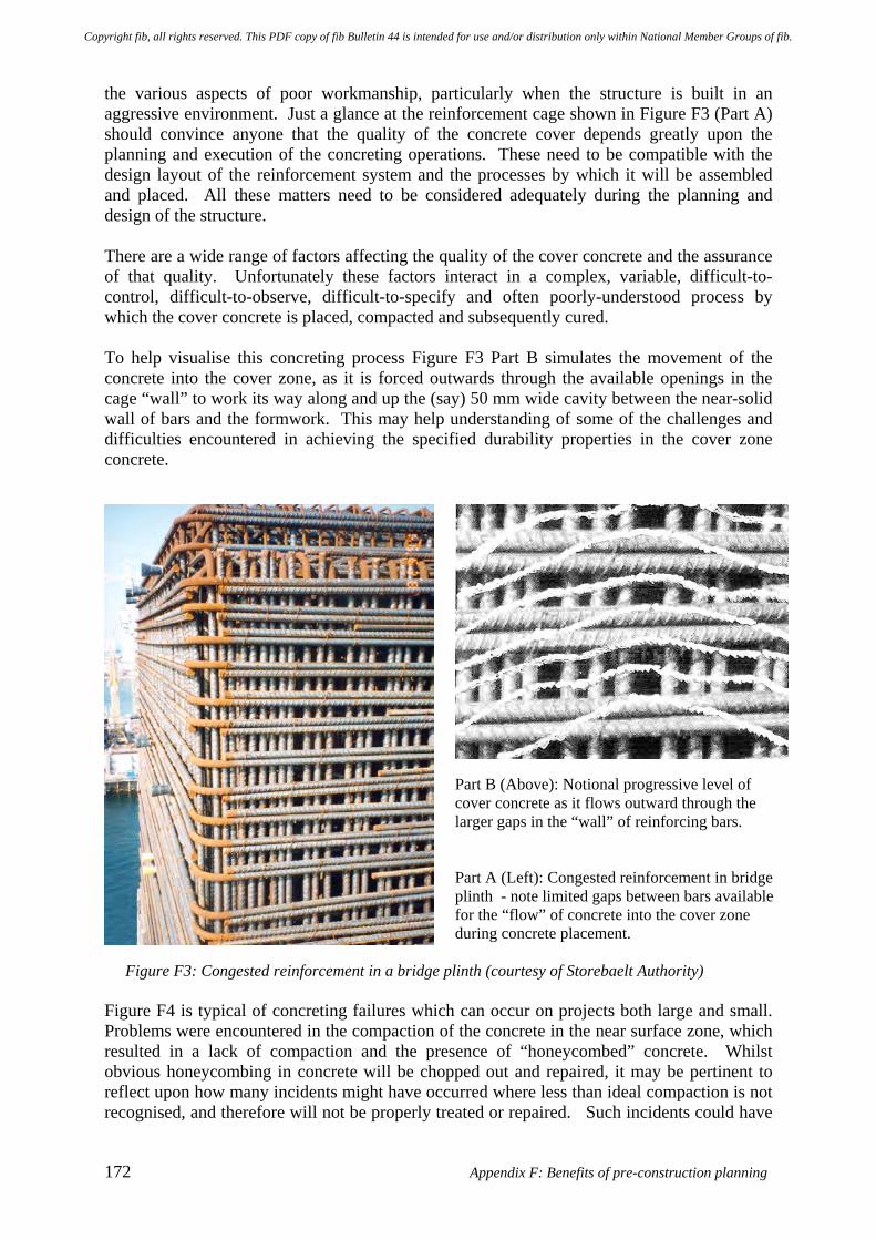
172 Appendix F: Benefits of pre-construction planning
the various aspects of poor workmanship, particularly when the structure is built in an aggressive environment. Just a glance at the reinforcement cage shown in Figure F3 (Part A) should convince anyone that the quality of the concrete cover depends greatly upon the planning and execution of the concreting operations. These need to be compatible with the design layout of the reinforcement system and the processes by which it will be assembled and placed. All these matters need to be considered adequately during the planning and design of the structure. There are a wide range of factors affecting the quality of the cover concrete and the assurance of that quality. Unfortunately these factors interact in a complex, variable, difficult-to-control, difficult-to-observe, difficult-to-specify and often poorly-understood process by which the cover concrete is placed, compacted and subsequently cured. To help visualise this concreting process Figure F3 Part B simulates the movement of the concrete into the cover zone, as it is forced outwards through the available openings in the cage “wall” to work its way along and up the (say) 50 mm wide cavity between the near-solid wall of bars and the formwork. This may help understanding of some of the challenges and difficulties encountered in achieving the specified durability properties in the cover zone concrete.
Part B (Above): Notional progressive level of cover concrete as it flows outward through the larger gaps in the “wall” of reinforcing bars. Part A (Left): Congested reinforcement in bridge plinth - note limited gaps between bars available for the “flow” of concrete into the cover zone during concrete placement.
Figure F3: Congested reinforcement in a bridge plinth (courtesy of Storebaelt Authority) Figure F4 is typical of concreting failures which can occur on projects both large and small. Problems were encountered in the compaction of the concrete in the near surface zone, which resulted in a lack of compaction and the presence of “honeycombed” concrete. Whilst obvious honeycombing in concrete will be chopped out and repaired, it may be pertinent to reflect upon how many incidents might have occurred where less than ideal compaction is not recognised, and therefore will not be properly treated or repaired. Such incidents could have
Copyright fib, all rights reserved. This PDF copy of fib Bulletin 44 is intended for use and/or distribution only within National Member Groups of fib.
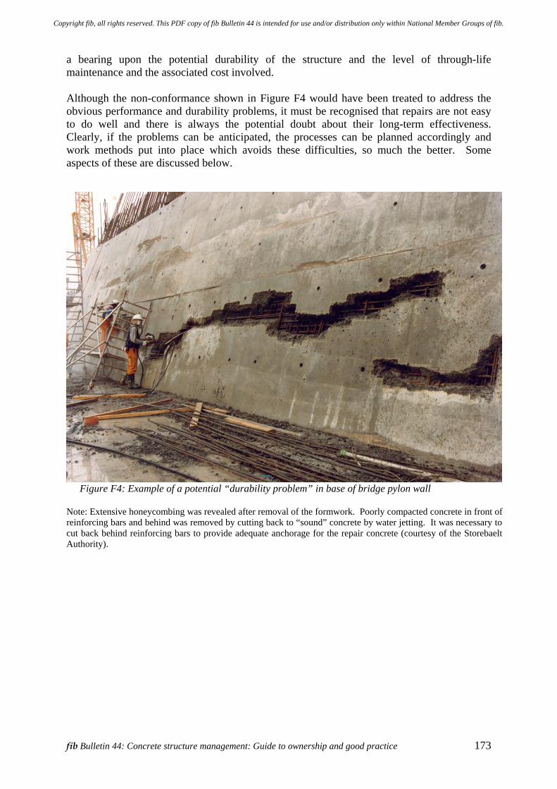
fib Bulletin 44: Concrete structure management: Guide to ownership and good practice 173
a bearing upon the potential durability of the structure and the level of through-life maintenance and the associated cost involved. Although the non-conformance shown in Figure F4 would have been treated to address the obvious performance and durability problems, it must be recognised that repairs are not easy to do well and there is always the potential doubt about their long-term effectiveness. Clearly, if the problems can be anticipated, the processes can be planned accordingly and work methods put into place which avoids these difficulties, so much the better. Some aspects of these are discussed below.
Figure F4: Example of a potential “durability problem” in base of bridge pylon wall
Note: Extensive honeycombing was revealed after removal of the formwork. Poorly compacted concrete in front of reinforcing bars and behind was removed by cutting back to “sound” concrete by water jetting. It was necessary to cut back behind reinforcing bars to provide adequate anchorage for the repair concrete (courtesy of the Storebaelt Authority).
Copyright fib, all rights reserved. This PDF copy of fib Bulletin 44 is intended for use and/or distribution only within National Member Groups of fib.
174 Appendix F: Benefits of pre-construction planning
F.3 Segment 1: Investigation of potential concrete supply problems
This segment might consume perhaps 10% of additional effort invested in pre-planning. Matters concerned with the source of aggregates, cement, water etc. might be identified by posing questions such as:
Q1: Have all potential deterioration problems due to aggregate reactivity been adequately addressed - for all potential aggregate sources?
Q2: Have the relevant properties of the proposed / approved cement, along with other cementitious materials, been adequately researched and tested?
Q3: Have any potential durability problems associated with the proposed water supply been adequately investigated?
Matters concerned with concrete batching plants which are being seriously assessed to supply concrete for the project, including the associated levels of control and the mix designs required might be identified by posing questions such as:
Q4: How accurately can the total water content of each batch be measured? Q5: What are the causes of significant variations in water content of the concrete
and how difficult are these to control? Q6: How can these variations be monitored and minimised? Q7: What is the range of variation from the nominal or nominated water content
which can reasonably be expected between batches delivered to site and used in the “final works” of the project?
For each proposed mix design for members where the durability requirements are critical:
Q8: What are the critical durability criteria – should these include parameters such as shrinkage, the tendency to crack, resistance to chloride penetration and others ?
Q9: Can a reliably consistent, quantitative relationship be established between the standard acceptance criterion for concrete delivered to the site and the critical durability criteria?
F.4 Segment 2: Research into verification of durability
This segment concerns research into test criteria and procedures for verifying durability and might consume perhaps 10% of additional effort invested in pre-planning. Matters concerned with concrete durability criteria might be identified by posing questions such as:
Q10: Does the specified test procedure accurately represent the actual concrete deterioration process (such as the depassivation process) which is expected to occur in the structure?
Q11: Does the test have a satisfactory level of accuracy over the full range of water/cement ratios at which the concrete will be supplied?
Copyright fib, all rights reserved. This PDF copy of fib Bulletin 44 is intended for use and/or distribution only within National Member Groups of fib.
fib Bulletin 44: Concrete structure management: Guide to ownership and good practice 175
Q12: Can the test criteria for accepting the mix design be accurately correlated with the test criteria for routine acceptance of batches of concrete delivered to the site?
Matters concerned with concrete sampling and testing procedures might be identified by posing questions such as:
Q13: Is the specified sampling procedure such that the test samples are always a true representation of the concrete in the cover zone?
Q14: Do the specified requirements for preparation and curing of the test specimens ensure that the acceptance test procedure will accurately represent the method of curing which will be used on the concrete in the structure?
F.5 Segment 3: Trial concrete mixes
This segment might consume perhaps 20% of additional effort invested in pre-planning. Having established preliminary answers to the above questions, the mix design process can now proceed in accordance with the following steps. During this process it may be discovered that the preliminary answers to the above questions (Q1 to Q14) may not be adequate. In this case further research and investigation may be necessary.
a) Determine the allowable range of water-cement ratio. b) Determine the corresponding range in the chosen durability criteria. c) Determine the experimental relationship between "durability" and the water-cement
ratio over the allowable range, and d) Repeat a, b and c if necessary. e) Confirm the nominal mix and allowable range of water-cement ratio.
During the mix design process the principles embodied in Figure F5 need to be understood by all personnel in the contractor's and concrete supplier's organization, as well as by all process verification (QA) personnel. In particular, they should be aware that the lower level of water content must be accurately controlled and recorded, as this affects placing and compaction of the concrete. It is essential that the water content be kept above a predetermined lower limit to prevent shrinkage cracking. All responsible personnel should be aware of the vulnerability that concrete slabs have to surface cracking when the concrete is placed at low water-cement ratios, particularly under conditions of low ambient humidity. The impact of the upper level of water content must also be accurately controlled and recorded, as this impacts upon the potential durability of the concrete in other ways. Figure F5 identifies the conundrum experienced in relation to the prediction of the service life of a concrete structure and determining which value of water-cement ratio should be employed in these evaluations?
Copyright fib, all rights reserved. This PDF copy of fib Bulletin 44 is intended for use and/or distribution only within National Member Groups of fib.
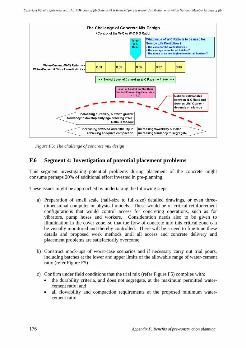
176 Appendix F: Benefits of pre-construction planning
Figure F5: The challenge of concrete mix design
F.6 Segment 4: Investigation of potential placement problems
This segment investigating potential problems during placement of the concrete might consume perhaps 20% of additional effort invested in pre-planning. These issues might be approached by undertaking the following steps:
a) Preparation of small scale (half-size to full-size) detailed drawings, or even three-dimensional computer or physical models. These would be of critical reinforcement configurations that would control access for concreting operations, such as for vibrators, pump hoses and workers. Consideration needs also to be given to illumination in the cover zone, so that the flow of concrete into this critical zone can be visually monitored and thereby controlled. There will be a need to fine-tune these details and proposed work methods until all access and concrete delivery and placement problems are satisfactorily overcome.
b) Construct mock-ups of worst-case scenarios and if necessary carry out trial pours,
including batches at the lower and upper limits of the allowable range of water-cement ratio (refer Figure F5).
c) Confirm under field conditions that the trial mix (refer Figure F5) complies with:
• the durability criteria, and does not segregate, at the maximum permitted water-cement ratio; and
• all flowability and compaction requirements at the proposed minimum water-cement ratio.
Copyright fib, all rights reserved. This PDF copy of fib Bulletin 44 is intended for use and/or distribution only within National Member Groups of fib.
fib Bulletin 44: Concrete structure management: Guide to ownership and good practice 177
d) Compile a comprehensive list of all significant potential concreting and concrete supply problems, together with appropriate preventive actions to minimise the risk of each identified problem occurring.
These activities will require the input of experienced construction engineers, foremen and operators to liaise with the designer and concrete supplier to ensure that avoidable concreting problems are not incorporated into the design of the final works and the construction processes.
F.7 Segment 5: Finalise construction requirements in project specification
This segment seeks to finalise the construction requirements for the project specification, it might consume perhaps 20% of additional effort invested in pre-planning. These issues might be approached by undertaking the following steps:
a) Prepare necessary supplements to the: • Concrete production standard(s) • Execution standard for concrete structures • Standards (ISO 9001) for quality planning and verification, including
development of the associated requirements for procurement and process control, and relevant site management and interface issues,
to ensure that the project specification addresses all identified potential concreting and concrete supply problems.
b) Prepare guide project plan procedures, including monitoring procedures, to address all
concreting problems identified above. c) Prepare schedule of items and quantities for insertion into the project specification.
These activities are crucial. If they are not done effectively and comprehensively, the necessary control and verification of the concreting processes will not happen. As a result the durability of the structure will not be assured.
F.8 Segment 6: Provision of adequate resources for quality management
This segment addresses the provision of adequate resources for quality management, particularly the personnel needed for monitoring construction processes, and might consume perhaps 20% of additional effort invested in pre-planning. These issues might be approached by undertaking the following steps to ensure:
a) All "special processes" are verified by appropriate physical inspection / visual monitoring / surveillance by appropriately qualified and experienced independent staff dedicated to these activities.
b) Quality records are to include the nature, location and extent of all significant
observed non-conformances. These are to include suspected non-conformances which may be recorded as potential non-conformity notifications. The records must also
Copyright fib, all rights reserved. This PDF copy of fib Bulletin 44 is intended for use and/or distribution only within National Member Groups of fib.
178 Appendix F: Benefits of pre-construction planning
include corrective action reports by which the non-conformance was rectified and the approved preventive actions which were implemented to prevent future non-conformances of this nature (corrective / preventive action reports). Where effective repairs are not possible this will require commitment from the contractor to provide ongoing maintenance / protection of the non-conforming component.
c) Effective, practical auditing of the contractor's quality system, particularly the procedures for process control and verification of critical concreting operations.
Segment 6 is an appeal for the return of effective process monitoring, which is widely recognised as a vital missing element in many of today’s construction projects. However, for this to happen, in the end it has to be paid for by the owner. It would be preferable that the owner accepts to pay for these activities at the outset, rather than chase what may prove to be a false economy. Furthermore, potential contractors and sub-contractors must be assured that if they price for the specified quality requirements in their tender, they will not be undercut by competitors who do not. Figure F2 indicates that the savings which occur in the later stages of construction (the second part of Segment 6) should largely compensate for the necessary pre-contract and pre-construction work carried out as indicated in Segments 1 – 5 and in the first part of Segment 6.
Copyright fib, all rights reserved. This PDF copy of fib Bulletin 44 is intended for use and/or distribution only within National Member Groups of fib.
fib Bulletin 44: Concrete structure management: Guide to ownership and good practice 179
Appendix G: Project specifications – An owner’s tool G.1 General
The service life of a structure and its associated through-life management costs and environmental impacts3 are largely determined by the achievement of appropriately specified durability related requirements (or conversely the failure to define them and / or to achieve them) set down in the project specification for the design and construction of a concrete structure. The project specification, incorporating the execution specification and project-specific quality plan requirements, provides the owner and his professional team with a means of defining and achieving the standard of performance they require from the structure. It is critical that appropriate information is included in the tender and contract documents which provide the legal and financial foundation for all aspects of procuring the desired concrete structure. Thus owners and their professional teams need to know how to draw up appropriate tender and contract documents to ensure that problems do not occur which could diminish the actual durability of the structure below the level that is required. The centrepiece of these documents is the project specification. The goal is that these documents should incorporate the necessary preventive action requirements and effective control procedures, as explored in Appendix F and discussed later, and that they should not simply create a “forms for forms sake” based approach to quality management. This informative appendix gives guidance upon some aspects which can be included in the project specification for a concrete structure. This guidance could have a significant impact upon through-life management costs and environmental impacts. These issues relate particularly to the execution of construction and to quality plan requirements when the structure is being built. Many of the considerations also potentially apply directly to certain types of structural concrete repair works, particularly those which involve the recasting of part or all of a concrete component. The philosophical points which underlie these considerations also apply more generally to other forms of intervention works upon structural concrete components. In what follows the term execution is used to refer to all the physical activities undertaken for the physical completion (construction) of the works. These activities include procurement, scaffolding, falsework, formwork, reinforcement, concreting, curing etcetera; as well as the related inspection and documentation of those activities. The usage of this term is consistent with the convention adopted in European and international technical construction standards, as discussed below.
3 In some instances the environmental impacts will be primarily concerned with those relating to the embodied energy employed to manufacture the materials used and the process involved in their placement in the structure. However in other circumstances the environmental impacts could also involve the operational energy used during the life of the structure. In the case of a building the operational energy component could be that used for heating, cooling, lighting, business activities, repairs, refurbishment etc. For a building the operational energy used throughout its life will often be an order of magnitude larger than the embodied energy associated with its construction. In the case of elements of concrete infrastructure (eg. bridges) the operational energy might be that associated with activities such as repairs, refurbishment, etc. However, these activities are likely to involve a degree of disruption to the function of the structure. In the case of a bridge, this would be the passage of traffic and the operational energy component might be considered to be that associated with the traffic. Where the passage of traffic is disrupted by repair works, the operational energy component might be taken to be the energy wasted by queuing traffic (ie. a form of consequential cost / environmental impact). Studies have shown that in these circumstances the environmental impacts of the energy wasted can soon exceed those relating to the embodied energy associated with construction.
Copyright fib, all rights reserved. This PDF copy of fib Bulletin 44 is intended for use and/or distribution only within National Member Groups of fib.
180 Appendix G: Project specifications – An owners tool
It is the tender and contract documents which set out the client defined requirements to which the design and execution processes for a concrete structure should be carried out, with detailed arrangements being dependent upon the actual procurement route adopted. Thus attention given to these matters is expected to achieve tangible improvements in the certainty of the durability of the concrete structure being built, especially if a long service life is demanded in an aggressive environment. This can be achieved by means of project specific requirements set down in a project execution specification compatible with the requirements of European and international codes of practice for concrete structures, as explained below. This appendix considers how a project specification and associated contractual documentation may draw upon codes of practice for the design and the execution of concrete structures, as well as how these aspects may link with project quality management processes. The issues are illustrated by consideration of European and international codes of practice for concrete structures and for quality management. This provides an insight into contemporary and forthcoming industry practice and illustrates how the owner and his professional team can use the project specification to enhance the certainty that the desired durability will be achieved, thereby helping to minimise through-life costs and environmental impacts of the concrete structure concerned. Summarising, the following sections discuss the preparation of project specifications, including execution and quality plan requirements, for inclusion in tender and contract documents for the design, construction and repair of reinforced concrete structures. The goal is to achieve predictable long service-life and to prevent premature deterioration. Perhaps most importantly from the point of view of an owner, these sections help highlight issues which might result in unplanned remedial works costs, and thereby aid in the identification of actions which should help to avoid such situations.
G.2 The benefits of “thinking construction”
By "thinking construction" long before the construction process actually starts on site, designers develop a construction-focused approach which potentially leads not only to a reduction in construction problems and costs, improvements in health and safety for those involved in the construction, which helps increase the certainty of that the desired outcomes will be achieved, but also to reduced intervention costs over the life of the structure. The benefits to be gained from pre-construction planning are discussed in Appendix F, along with a process that might be followed. If a “thinking construction” culture can be developed from the bottom-up, designers are more likely to appreciate the practical problems faced by the workers involved in preparing formwork and falsework, fixing reinforcement and placing concrete. This is important if these workers are to be encouraged to use their initiative and to recognise and eliminate conditions adverse to quality, which could result in nonconforming work that does not meet the longer-term durability related goals for the structure. To be successful and gain the maximum benefit, the “thinking construction” approach also needs to be actively and practically promoted from the top in all the organisations involved. This appendix seeks to draw upon principles which are most relevant to construction quality management in order to propose project planning activities which can be undertaken by the owner and his professional team, particularly in respect of the processes of inspection. This
Copyright fib, all rights reserved. This PDF copy of fib Bulletin 44 is intended for use and/or distribution only within National Member Groups of fib.
fib Bulletin 44: Concrete structure management: Guide to ownership and good practice 181
approach should enable the owner and his professional team not only to establish the standard of execution necessary and that the owner is prepared to pay for, but also the definition of the execution requirements to be incorporated in the tender documents. This should ensure that clearly specified project related requirements are in place and used, thereby reducing the possibility that doubtful or inappropriate assumptions may be made by the constructor about the level of project management, site organisation and workmanship that will be necessary. As a result, both at tender stage and during the works, contractors and repair specialists will know better what they have to provide and what the owner / his professional team can be expected to provide. If all else fails these actions would at least provide a basis for negotiation if disputes should arise about inspection and related execution requirements. As noted above, these principles apply just as much to concrete repair and reconstruction operations as they do to new construction.
G.3 Standards for concrete structures and quality management
G.3.1 Introduction
Europe has developed an integrated suite of technical standards for the principal construction materials. In the current context we are only concerned with those relating to the design and construction of concrete structures. Figure G1 shows the main modules and the hierarchy of the system of European technical construction standards which provide a basis for the design, execution and selection of materials for concrete structures. The European and international approach is used to illustrate philosophical points which are expected to apply more widely and in other parts of the world using different systems for technical standards. In this context it is also relevant to note that the International Standards Organisation document for the execution of concrete structures (ISO / DIS 22966) is very similar to EN 13670, the applicable European technical construction standard. Thus the principles explained and recommended in this appendix should be applicable to either document, giving a wider potential impact. Both documents are expected to become available for use during 2008. Another reason for focusing on the European documents is that they are likely to become de facto standards in numerous countries outside Europe.
G.3.2 Hierarchy of European Standards and the Execution Standard
The European technical construction standards sit beneath the national building legislation and regulations applicable to the country in which the structure is to be situated. EN 13670 applies to the execution of concrete structures to achieve the intended level of safety and serviceability during the design service life, as defined by EN 1990 – Basis for structural design and EN 1992 – Design of concrete structures (using the Nationally Determined Parameters which relate to issues of safety as applicable in the country of use). The Execution Standard (EN 13670) has three functions, namely:
• To transfer the requirements set during design to the construction (ie. to be the link between design and construction).
Copyright fib, all rights reserved. This PDF copy of fib Bulletin 44 is intended for use and/or distribution only within National Member Groups of fib.
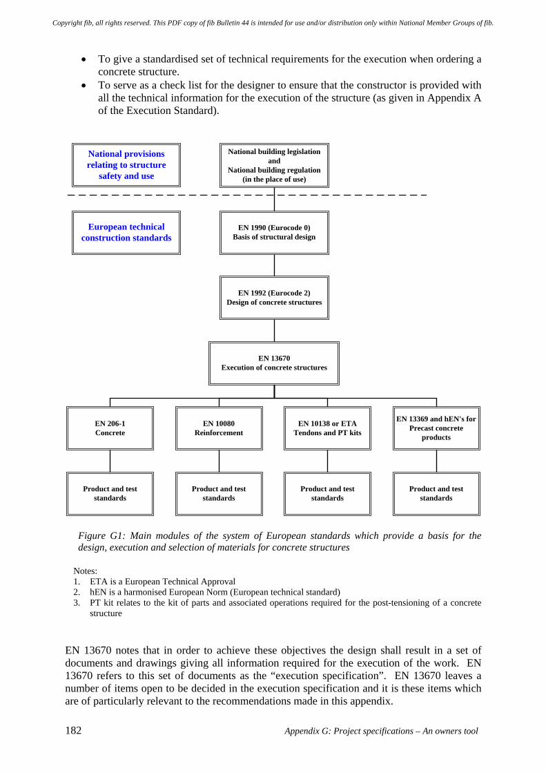
182 Appendix G: Project specifications – An owners tool
• To give a standardised set of technical requirements for the execution when ordering a concrete structure.
• To serve as a check list for the designer to ensure that the constructor is provided with all the technical information for the execution of the structure (as given in Appendix A of the Execution Standard).
National building legislationand
National building regulation(in the place of use)
EN 1990 (Eurocode 0)Basis of structural design
EN 1992 (Eurocode 2)Design of concrete structures
EN 13670Execution of concrete structures
EN 10080Reinforcement
EN 10138 or ETATendons and PT kits
Product and teststandards
Product and teststandards
EN 206-1Concrete
EN 13369 and hEN's forPrecast concrete
products
Product and teststandards
Product and teststandards
National provisionsrelating to structure
safety and use
European technicalconstruction standards
Figure G1: Main modules of the system of European standards which provide a basis for the design, execution and selection of materials for concrete structures
Notes: 1. ETA is a European Technical Approval 2. hEN is a harmonised European Norm (European technical standard) 3. PT kit relates to the kit of parts and associated operations required for the post-tensioning of a concrete
structure EN 13670 notes that in order to achieve these objectives the design shall result in a set of documents and drawings giving all information required for the execution of the work. EN 13670 refers to this set of documents as the “execution specification”. EN 13670 leaves a number of items open to be decided in the execution specification and it is these items which are of particularly relevant to the recommendations made in this appendix.
Copyright fib, all rights reserved. This PDF copy of fib Bulletin 44 is intended for use and/or distribution only within National Member Groups of fib.
fib Bulletin 44: Concrete structure management: Guide to ownership and good practice 183
G.3.3 Quality management in the Execution Standard
In the Execution Standard the requirements for quality management are specified in terms of three Execution Classes (1, 2 and 3), for which the required “strictness” increases from Class 1 to Class 3. This gives the option to specify the required level of quality management based upon the importance of the structure / component and the criticality of the execution to its ability to fulfil its intended function. The three execution classes are intended to correspond to the three levels of reliability differentiation given in EN 1990 Annex B. This implies that the achieved quality of construction should increase from Class 1 to Class 3, but no explicit performance related definition of this achievement is given. Instead the Execution Standard relates the three execution classes to the type of inspection to be carried out, who should carry out the inspection and to what standard, the extent of the inspection and whether an inspection report is required. The associated categories of activities and requirements are defined in Table 3 of the Execution Standard as follows. Inspection Parameter
Defined Requirement or Category of Activity
The type of inspection • Visual inspection and random measurements • Visual inspection and systematic and regular
measurements of major works • Visual inspection and detailed inspection of all
works which are significant for the load-bearing capacity and durability of the structure
The party which carries out the inspection (and to what standard)
• Self inspection • Inspection in accordance with the procedures of
the constructor • Additional requirements defined by the
execution specification
The extent of the inspection • All works • Systematic and regular inspection of the works
Requirement for an inspection report
• Not required • Required
Note: Inspection in this context is defined as conformity evaluation by observation and judgement accompanied as appropriate by measurement, testing or gauging.
Copyright fib, all rights reserved. This PDF copy of fib Bulletin 44 is intended for use and/or distribution only within National Member Groups of fib.
184 Appendix G: Project specifications – An owners tool
The Execution Standard defines inspection requirements for: • Materials and products to be incorporated into the permanent works • The execution activities include the provision of scaffolding, falsework, formwork,
reinforcement, prestressing, embedded items, erection of precast items, site transport, casting and curing of concreting and as-built geometry.
The Execution Standard defines quality management in terms of inspection requirements as outlined above, but it makes no direct reference to ISO 9001 and related quality management standards. However, provision is made for a quality plan "if required by the execution specification". By the same token, there is no requirement in the Execution Standard for ISO 9001 auditing, but technical auditing could be an important part of the Class 3 inspection activities defined by the Execution Standard.
G.3.4 Quality management standards – ISO 9000 series of standards
Consideration also needs to be given to the contribution which can be made by quality management processes. Whilst ISO 9001 is accepted world-wide as the model approach for quality management, its implementation for the construction of concrete structures on site can present various difficulties. There was a change in the focus of the third (2000) edition of ISO 9001. This adopted the concept of the “continual improvement” of an organisation's management system in order to improve overall performance and customer satisfaction. Whilst this is better suited to the continued evolution and improvement of an organisation, it did represent a move away from the stated “primary aim” of the earlier (1987 and 1994) editions of ISO 9001 - which were concerned with “preventing nonconformity at all stages from design through to servicing”. It might be argued that the process control philosophy of the earlier editions of ISO 9001 was more compatible with the needs of assuring quality in the “one-off” circumstances associated with the site placement of concrete in a particular structure or component. Typically the site environment is very different to that of a “factory” involved in the production of standard items using a continuously repeated manufacturing process. The “factory” circumstances are well suited to a process of continual improvement. However, it should also be recognised that the concept of the “continual improvement” can make a major contribution to establishing an appropriate ethos in the organisation undertaking the construction of concrete structures on site. Both aspects have a role to play. Quality assurance (QA) is a term which has strong associations with the sampling and testing / inspection systems developed by suppliers to guarantee the quality of their product. An example of this is the premixed concrete industry. However, for concrete structures and other major concrete works, the emphasis placed on the product testing / inspection aspects of quality assurance needs to be accompanied by a greater emphasis on the process control and monitoring aspects of the (site) execution works. Also, it is increasingly recognised in the construction industry that “a form filling / box ticking approach” does not contribute to the achievement of actual quality on site during the construction process. It is also suggested in some quarters that the ability of people to self-regulate should be restricted because there are numerous examples where self-regulation has not worked satisfactorily. Problems tend to occur in situations where people are faced with
Copyright fib, all rights reserved. This PDF copy of fib Bulletin 44 is intended for use and/or distribution only within National Member Groups of fib.
fib Bulletin 44: Concrete structure management: Guide to ownership and good practice 185
conflicting priorities. It is proposed that there is a need for the standard of site / process supervision to be related to the circumstances appertaining and, in light of this, many contractors are adopting a risk-based approach and related methodology to quality management. This could provide a way forward. The issues of risk management, the preparation of a project quality plan and the linkages between these activities, including the concept of risk based quality management is discussed in Section 8.4. In essence a risk management plan and a quality management plan have the same objective. Both seek to identify risks and potential problems. Their aim is to ensure that appropriate preventive actions are developed and implemented as effectively and as early as possible during the course of design and execution. Ideally risk awareness processes will be included right from the start of the conceptual development of the proposed scheme in order to support choices between possible alternatives and to avoid the potential need for future preventive actions, as has been illustrated by the discussion of Figures 2 and 3 in the main text.
G.4 Improving the certainty of achieving durable concrete structures
Most concreting processes should be considered to be "special processes" because process deficiencies may not be evident initially and will become apparent only after the product (ie. the concrete structure) is in use. In the context of the current discussion the product is typically the cover concrete of the structural element concerned and the potential deficiency will be in the durability and / or the length of time that the structural element performs satisfactorily without some form of preventive or remedial intervention. The term "special processes" was originally defined in ISO 9001: 19874 and this definition is still appropriate in the context of the construction of concrete structures. It was defined as follows:
"These are processes, the results of which cannot be fully verified by subsequent inspection and testing of the product and where, for example, processing deficiencies may become apparent only after the product is in use. Accordingly, continuous monitoring and / or compliance with the documented procedures is required to ensure that the specified requirements are met."
For example, deficiencies in the construction process may compromise the quality of the cover concrete (eg. lack of compaction or excessive permeability for whatever reason, but perhaps due to inadequate curing) or its thickness (ie. distance over the reinforcing bars). In such circumstances the cover concrete may then not provide adequate protection to the reinforcing bars for the environment in which the structure is situated. Inadequate protection5 commonly results in premature corrosion of the reinforcing bars and spalling of concrete. Premature deterioration will usually necessitate some form of preventive or remedial intervention being made before the end of the required service life period. Such interventions may have only a limited life, with further interventions being necessary in due course; all of which add to the cost and environmental impacts incurred and to the potential disruption of the operation of the structure or facility that it forms part of.
4 ISO 9001: 1987: Quality management systems - Requirements, ISO, 1994 (withdrawn) 5 Although the aggressive elements in the environment vary, the main causes of deterioration of reinforced concrete structures are carbonation or chloride ion induced corrosion of the embedded reinforcing bars.
Copyright fib, all rights reserved. This PDF copy of fib Bulletin 44 is intended for use and/or distribution only within National Member Groups of fib.

186 Appendix G: Project specifications – An owners tool
Thus the implication is that deficiencies in the construction process need to be avoided. Essentially there is only one opportunity to “get things right first time”, which is when the concrete for the structure is cast. Figures F3 and F4 (Appendix F) illustrate the challenges that may be faced and the potential “durability problems” that may be encountered and need to be overcome. It should also be recognised that deficiencies also include situations where geometrical variations on cover to the reinforcement exceed the allowable geometrical tolerance values (ie. the nominal cover value less the permitted tolerance). In the case of a reinforcing cage similar to that illustrated in Figure F3, the challenge would be to ensure that the concreting processes are so effectively controlled when casting the concrete that the cover zone is completely filled with concrete of the specified quality; and that this can be verified to the satisfaction of the owner and his professional team. Ideally the design and construction process would be controlled in a sufficiently effective manner that the reinforcing cage produced would not be similar to that illustrated in Figure F3. The goal would be to avoid creating a situation where problems of concrete placement and compaction were likely to occur. Thus a reinforcing cage where the bars effectively create a wall should ideally be designed out, thereby avoiding the potential problems. The goal of greater certainty of achieving the desired durability can be delivered by taking the Execution Standard as the starting point and developing a set of project specific requirements set down in the project execution specification. This approach would use the effective application of process analysis, employing the process visualisation and risk evaluation activities discussed in Appendix F, to ensure that execution is controlled and verified by well planned and documented preventive procedures. It is possible to meet the objective of ensuring the durability of the structure by defining inspection clauses in a way that goes beyond the minimum requirements of the Execution Standard. It is for the owner and his professional team to take advantage of the provisions incorporated in the Execution Standard to improve the certainty of achieving the desired quality / standard of execution required. Essentially the Execution Standard comprises a generic set of construction requirements from which it is expected that the specifier will define requirements which are appropriate for a specific project or member type. It is also expected that the specifier will do this through appropriate clauses introduced into the execution specification, as required to address the specific needs of a particular project or member type. Annex A of the Execution Standard provides a convenient mechanism for identifying the clauses (in the Execution Standard) which can be used to produce the required project execution specification. This is done through Table A1 of the Execution Standard, which is a checklist of the clauses identifying parameters to be defined to suit project specific requirements. This may involve providing project specific requirements for only a few, but possibly many, of the standard clauses. An example is given in Section G.7.2 to illustrate the application of Annex A and Table A1 of the Execution Standard. However, there may also be a need to insert additional clauses (requirements) into the execution specification in order to enhance the certainty that the desired durability will be achieved. These clauses are additional to those in the Execution Standard. Some suggestions
Copyright fib, all rights reserved. This PDF copy of fib Bulletin 44 is intended for use and/or distribution only within National Member Groups of fib.
fib Bulletin 44: Concrete structure management: Guide to ownership and good practice 187
for, and examples of, additional clauses are given later in this appendix [refer Sections G.7.3 and G.7.5]. This mechanism would enable designers to go beyond the assumptions currently made during the development of their designs that adequate levels of workmanship, site management and project supervision will be achieved during construction in all circumstances, even in aggressive environments. In such demanding circumstances the commonly made assumptions have been frequently be found to be not good enough. More needs to be done to provide assurance that the quality, and hence durability, required for satisfactory through-life performance will be achieved. As noted before, effective inspection processes can help provide greater certainty of achieving the desired outcome, which is conformity to the specified strength and durability requirements. Effective inspection can be summarized “as the right concentration of effort and resources involving the right people at the right time and in the right place”. When preparing for the casting of the concrete elements concerned, effective inspection is essential to give reliable assurance that the specified quality will be achieved. Post-construction, effective inspection is essential to be able to give verification that the specified quality has been achieved.
G.5 Execution management and the requirement for supporting plans
In the Execution Standard Clause 4 is entitled “Execution management”, but is in effect a summary of the assumptions which are typically applied to a construction project. These assumptions include items such as:
• “the availability of a comprehensive design for the structure”, • “a project management in charge of the supervision of the works which will enable
the execution of a conforming structure” and • “a site management which will take charge of the organisation of the works and
enable the correct and safe use of equipment and machinery, the satisfactory quality of materials, the execution of a conforming structure and its safe use up to the delivery of the works”.
If these assumptions are not appropriate or do not apply to the project, suitable requirements need to be specified. These requirements might be defined under the following broad headings:
• Inspection Plan, and a • Concreting Plan, which in turn might be supported by other subsidiary plans such as:
o Reinforcement Plan o Formwork Plan o Falsework Plan, and o Post-tensioning Plan
G.6 The Execution Standard and the Inspection Plan
Clause 4.3 and Annex B of the Execution Standard refer to "quality management", but in this context "quality management" is actually concerned with the definition and application of supervision and inspection activities. Such activities, which are required for the verification of the control processes put in place to achieve the desired quality in the concrete structure (the final works), are often referred to as quality assurance (QA).
Copyright fib, all rights reserved. This PDF copy of fib Bulletin 44 is intended for use and/or distribution only within National Member Groups of fib.
188 Appendix G: Project specifications – An owners tool
The Execution Standard defines inspection requirements for:
• Materials and products to be incorporated into the permanent works • The execution activities, including the provision of scaffolding, falsework, formwork,
reinforcement, prestressing, embedded items, erection of precast items, site transport, casting and curing of concreting and as-built geometry.
Concreting processes will require an Inspection Plan, appropriate to the circumstances, for the execution activities detailed above. These requirements are likely to be particularly important for major or complex concrete pours. Inspection requirements should be applied to both site-cast and factory-cast concretes as appropriate, but the details of these regimes may differ. The Inspection Plan will need to address at least the following issues at each location to be inspected. The locations, or appropriate criteria to establish which locations on the structure should be inspected, would need to be defined in the execution specification.
• The requirements (as defined in the drawings, specification, etc) • The references to the standard and the execution specification • The method of inspection, monitoring and testing • The definition of the inspection section • The frequency of inspection, monitoring or testing • The acceptance criteria • The documentation • The responsible inspector • The possible involvement of other parties in the inspection.
As the inspection regime for Execution Class 3 may incorporate a significant component of inspection / verification by the owner or his agents, in addition to more traditional quality control (QC) and quality assurance (QA) roles by the constructor, it is imperative that the Inspection Plan requirements be included in the preliminary tender documents prepared by the owner or by his professional team. These requirements would therefore need to have been developed at least in outline form by tender stage. To achieve this the owner or his professional team must have given adequate consideration to requirements for inspection and / or verification and / or supervision and to how these responsibilities will be borne by the various parties.
G.7 The Execution Standard and the Concreting Plan
G.7.1 Introduction
Throughout the process of procurement and delivery of a project there will be a need for progressive planning and review of the design and construction processes, including the requirements for durability. All the necessary planning to achieve the desired quality in the concrete structure (the final works) should be incorporated into a Concreting Plan. In this way the requirements for effective planning are included in the relevant clauses of the execution specification. The control of these processes is commonly referred to as quality control (QC).
Copyright fib, all rights reserved. This PDF copy of fib Bulletin 44 is intended for use and/or distribution only within National Member Groups of fib.
fib Bulletin 44: Concrete structure management: Guide to ownership and good practice 189
When it is decided that a Concreting Plan and other project specific requirements are necessary, the Execution Standard provides mechanisms for the specific requirements to be incorporated via the project execution specification. For example, Clause 8.2 (1) of the Execution Standard states that "a concreting plan shall be prepared where required by the execution specification". Table A1 in Annex A of the Execution Standard provides a convenient checklist of information for inclusion in the execution specification. Thus in respect of Clause 8.2 (1), Table A1 notes that the execution specification should “state if a concreting plan is required". There is no reason why this approach might not be used to define other modified or additional execution requirements, should this be deemed to be appropriate.
G.7.2 Developing a specification clause for the execution specification
For a major concrete construction or remedial project; the need for a concreting plan could be addressed by project specific clauses incorporated into the project execution specification using the facility provided in Clauses 8.2 (1) and 4.1 (3) of the Execution Standard. For example, the clauses incorporated in the project execution specification might be as follows:
A Concreting Plan shall be prepared for each of the member types listed. The Concreting Plan (for a particular structural element) shall be defined as that component of the Project Quality Plan which specifies what procedures and associated resources shall be applied how, when, where and by whom to ensure the concreting processes are controlled and monitored effectively so as to provide the owner with assurance that the hardened concrete in that structural element will achieve its specified durability. A concreting sub-plan shall be prepared for a particular structural element / by or on behalf of each relevant sub-contractor (as appropriate). These sub-plans shall include:
• Design, detailing and scheduling of reinforcing steel • Investigation and design of concrete mix • Design and detailing of formwork • Supply and erection of formwork • Supply, placing and inspection of reinforcing steel • Supply of concrete • Placement and finishing of concrete • Curing of the concrete
The various sub-plans shall be integrated within the overall Concreting Plan - which shall itself be integrated with other components of the Project Quality Plan, including as appropriate those for reinforcement, formwork, falsework and post-tensioning. All sub-plans shall address and comply with the requirements of the relevant clauses of the Execution Specification.
Copyright fib, all rights reserved. This PDF copy of fib Bulletin 44 is intended for use and/or distribution only within National Member Groups of fib.
190 Appendix G: Project specifications – An owners tool
The requirements for a concreting plan shall be incorporated effectively in the preliminary design brief; and this requirement shall be progressively developed as design and construction proceed.
Using these types of clause a project execution specification could be drawn up which is appropriate and workable for that particular project / critical members. An owner / his professional team should find that a limited number of such specification clauses should address the needs of a particular project, with perhaps only minor changes required for each new project.
G.7.3 Linkage between the Concreting Plan with the Inspection Plan
Once the need for a Concreting Plan has been established, it is then possible to specify appropriate concreting plan and ancillary requirements which should ensure that the following objectives are achieved:
Objective 1. The necessary design and construction requirements are incorporated in the tender and contract documents.
Objective 2. That these requirements are faithfully complied with during the relevant construction operations.
Objective 3. The achievement of the required service life properties of the finished structure can be satisfactorily verified, to an acceptable degree of certainty.
If the first of these objectives is not achieved, it seems unlikely that the other two will be fully met. The first objective also needs to be achieved in a manner which is applicable to initial design briefs, as well as to design and "design and build" contracts. The first objective seeks to address the fact that many current construction projects: • Fail to recognise that a large proportion of construction problems result to some degree
from inadequacies in the relevant design details and / or specification requirements. • Need an effective process to assist the designer in minimising potential construction
problems (ie. within the execution specification). To overcome the difficulties experienced, the designer – on behalf of the owner – needs to include in the tender documents an Inspection Plan which shall specify the supervision requirements for all critical processes and member types; and designate how the responsibilities for inspection, monitoring and verification shall be distributed between the designer, the constructor, the owner and their agents. Appropriate items should be included in the tender schedule of items, against which amounts would be entered to provide for all supervision costs. The schedule should include details and an estimate of the value of the proposed supervision to be provided by the owner. Variations to the contract could be negotiated on the basis of the scheduled rates and related quantities. Comprehensive design shall be understood to include identification of potential construction problems and appropriate detailing and re-detailing as required to eliminate or minimise these problems. The identified potential problems, along with the requirements for their minimisation, could be recorded by means of appropriate notes on the drawings and with appropriate amendments made to relevant clauses in the execution specification.
Copyright fib, all rights reserved. This PDF copy of fib Bulletin 44 is intended for use and/or distribution only within National Member Groups of fib.
fib Bulletin 44: Concrete structure management: Guide to ownership and good practice 191
It will be necessary for relevant members of the project management team to familiarise themselves with the potential problems identified by the designers, in order that they can incorporate appropriate preventive actions in the procedures for the relevant components of the project quality plan. This would include as appropriate the Concreting Plan and associated sub-plans for reinforcement, formwork, falsework and post-tensioning activities. Progressively updated records should be kept of the potential and actual construction problems associated with design details, together with the methods adopted to eliminate or minimise them.
G.7.4 The Inspection Plan
The above issues could be addressed by clauses specifying project specific requirements in the project execution specification using the facility provided in Clauses 1 (2) and 4.1 (3) of the Execution Standard (that is to the Scope and to Execution management – Assumptions). For example, the clauses in the project execution specification might be worded as follows:
Inspection Plan As part of the tender documentation an outline Inspection Plan is provided by the designer which specifies the supervision requirements for all critical processes and member types. It designates how the responsibilities for inspection, monitoring and verification are to be distributed between the designer, the constructor and the owner, or their agents. Appropriate items are included in the tender schedule against which amounts are to be entered to provide for all supervision costs. The schedule includes details and an estimate of the proposed supervision to be provided by the owner. The relevant members of the project management team shall familiarise themselves with the potential problems identified by the designers, and shall incorporate appropriate preventive actions in the procedures of the relevant components of the Project Quality Plan. This would include as appropriate the Concreting Plan and associated sub-plans for Reinforcement, Formwork, Falsework and Post-tensioning. Progressively updated records shall be kept of the potential and actual construction problems associated with the design details, together with the methods adopted to eliminate or minimise them.
An example of a sub-plan supporting the Concreting Plan is given in Section G.7.5. This is a Reinforcement Plan, relating to the design, detailing and placement of reinforcement in structural concrete elements.
G.7.5 Procurement, production and delivery of concrete
In addition to the concreting processes, the Concreting Plan and the Inspection Plan must also address the risks of inadequate process control and "conditions adverse to quality" in the procurement, production and delivery of the concrete. While it is acknowledged that some countries have a comprehensive specification and QA system which is intended to prevent the supply of nonconforming concrete, such a QA system
Copyright fib, all rights reserved. This PDF copy of fib Bulletin 44 is intended for use and/or distribution only within National Member Groups of fib.
192 Appendix G: Project specifications – An owners tool
is based on assumptions about standards of workmanship and inspection which need to be examined on a project-specific basis. Moreover it is not realistic to assume that a concrete mix can be designed independently of site-specific requirements, especially if a long service life is demanded for a structure in an aggressive environment. Most obviously, if the proposed site curing regime is markedly different from that assumed by the concrete supplier; adjustments will need to be made to the test acceptance criteria. However, there are many other aspects of concrete supply which must be tailored to meet the constructor’s site requirements; or alternatively, the constructor would need to change the site conditions. In these circumstances, effective liaison between the constructor and the concrete supplier must be provided for in the Concreting Plan and the Inspection Plan. There are many aspects of the concrete production and delivery process which need to be progressively planned and reviewed. Amongst the most difficult is the selection of an appropriate durability criterion and a method for evaluating conformity to that criterion. In addition, it should be realised that many of the fundamental processes used by the concrete supply industry are in fact "special processes". For example, sampling is a special process, as are most testing processes, because once the test is completed it is difficult to verify by inspection that the testing process was carried out correctly. With respect to batching, the measurement of water content in aggregates is also a special process. Likewise, the addition of water in a batching operation is a special process, as there are no widely accepted tests for measuring or verifying the water content in a batch of concrete. As well as the potential problems associated with concrete supply, there are also the factors associated with the placement of concrete to take into account. These include the interface conditions between the flowing concrete and the assembly of formwork and reinforcement into and around which it has to be placed and compacted, along with other influences such as weather conditions.
G.7.6 The Reinforcement Plan
It was previously stressed that the assumptions made in the Execution Standard with respect to design, project management and site supervision should be questioned and appropriate project specific qualifying requirements introduced as necessary. Nowhere are these qualifying requirements likely to be more necessary than in the planning, design and detailing of steel reinforcing cages and during the subsequent placing of concrete in and around these cages. Figures F3 and F4 (Appendix F) have previously drawn attention to this need. It is a commonly observed reality that “fighting to get cover” or “getting the cover right” is a recurring problem for all forms of reinforced concrete construction, with potentially considerable significance for its durability. During construction this problem is usually not properly identified until the forms are closed up. Typically one of the first attempts at rectification of the deficiency is to try to force the reinforcing cage away from the form so that additional spacers can be entered into the gap created. These extra spacers are often precariously placed and may even be subject to crushing if the forces involved in displacing the reinforcing cage are high enough. It is often difficult to achieve much increase in cover by such force. It is also very time-consuming to
Copyright fib, all rights reserved. This PDF copy of fib Bulletin 44 is intended for use and/or distribution only within National Member Groups of fib.
fib Bulletin 44: Concrete structure management: Guide to ownership and good practice 193
check the adjusted cover thoroughly, as each ligature may have been forced individually and the cover will need to be gauged individually for each ligature. On the other hand, if the outside bars are stiff enough not to deflect appreciably between spacers, the checking of cover becomes a relatively simple matter using an appropriately sized “gauging block”. Getting the cover distance correct could eliminate the need for some of the 10 to 15 mm permitted deviation provided as geometric tolerances within Tolerance Class 1 in the Execution Standard (see Figure 3(b) EN 13670). These tolerances are considered normal for the standard of control and supervision achieved in many reinforcement placing operations. Smaller permitted deviations could correspond to those of Tolerance Class 2 in the Execution Standard (see Figure 3(b) EN 13670). Less scatter in the value of cover distance would help improve the predictability in the performance and durability of the structure (NB. As also would improved consistency of the properties of the hardened concrete). The project execution specification can be formulated in a manner which permits a certain percentage of cover distance values to be less than the required minimum cover (see Notes to Figure 3(b) EN 13670). This approach requires a statistical assessment of deviations in cover distance for the member / structure concerned. Confidence that the cover distance is correct would obviate the need for any requirement in the execution specification for such a statistical assessment, which would be time consuming and expensive to carry out. To reduce the chance of encountering the types of difficulties discussed, it is appropriate to consider the modifications and additions which might be made to the project execution specification in respect of Sections 6 (Reinforcement) and 8 (Concreting) of the Execution Standard. Similarly the Inspection Plan requirements would need to be reconsidered, and perhaps modified for the project taking account of the proposed method of procurement and the anticipated contractual arrangements. The example draft clauses presented below are only illustrative.
Reinforcement Plan Reinforcement design and detailing A plan for the design, detailing, scheduling, bending and fixing (including verification) of the reinforcement, shall be submitted as a subsidiary plan to the Concreting Plan. These requirements shall be applied in particular to those locations in reinforced and prestressed concrete members where congestion of reinforcement requires special consideration of reinforcement placing and concreting operations. Where considered necessary by the designer and / or the project manager and / or the site manager, enlarged detailed drawings or three-dimensional computer simulations of reinforcement details and / or physical models or mock-ups shall be prepared to ensure that the as-constructed formwork-reinforcement assembly provides adequate access for vibrators and pump hoses etc. For major and / or deep pours, a pre-planned pattern of pump discharge access ways shall be designed and constructed into the reinforcement assembly. The reinforcement detailer shall be responsible for ensuring not only that unobstructed access is provided for vibrators and pump hoses (extending to the bottom of the pour), but that necessary access is also provided (particularly in deep
Copyright fib, all rights reserved. This PDF copy of fib Bulletin 44 is intended for use and/or distribution only within National Member Groups of fib.
194 Appendix G: Project specifications – An owners tool
pours) for steel fixers, form workers, concrete workers and monitoring personnel to work safely and effectively within the reinforcement assembly – including the provision of effective lighting during the concreting operation. In critical situations where there is a high risk of non-conformity of the depth and / or quality of the cover concrete, trial pours shall be carried out to validate the chosen design / construction solution. Appropriate records shall be kept, including relevant sketches, photos and video clips. The detailing of the reinforcement shall take full account of the effects of laps in reducing the effective available space for concreting operations. Mechanical couplers or double lapped splice bars shall be used where required to ensure consistency of location of each bar in relation to the ligatures. Bundling of bars shall be designed and detailed into the reinforcement pattern wherever necessary to open up space for access ways to meet the requirements of the concreting plan. Templates shall be used during assembly to ensure that the necessary openings are maintained until the time of concreting. The designer / reinforcement detailer shall ensure that independent checking of the reinforcement design and bending schedules is carried out, to verify that cover distances are not compromised by localised “thickness build-up effects” due to laps, hooks, inserts etc. and any situation where intersecting bars have been assumed to occupy the same layer. Placement and inspection of reinforcement The project manager shall arrange for the necessary inspection, verification and validation exercises to be planned and executed progressively and in adequate time to ensure that significant design errors are identified and rectified before the nonconforming bars are bent and delivered in large quantities. For each major pour, the site supervisor shall ensure that representative small sections are assembled to verify conformity to access and cover requirements, prior to placing the bulk of the steel in that pour. For deep or complex pours, the conformity of the lower sections of the reinforcing assembly shall be verified before the addition of further bars makes it too difficult to monitor and rectify / relocate the bars in the lower section. This principle shall be applied progressively as the assembly is built up. Establishing and maintaining cover distance to wall steel reinforcement Reinforcement cages for walls and beams shall be designed so that the outermost layer of bars are horizontal, and support a system of spacers at predetermined intervals, to ensure deflections at and between spacers are negligible. The location of the sides of beams and wall cages shall be verified before the forms are closed up. The procedures for verifying the location of reinforcing cages before the formwork is closed up shall be included in the Concreting Plan. Out of position reinforcement shall be rectified before the formwork is closed up – in order that the spacers will not be used to force over the out of position bars.
Copyright fib, all rights reserved. This PDF copy of fib Bulletin 44 is intended for use and/or distribution only within National Member Groups of fib.
fib Bulletin 44: Concrete structure management: Guide to ownership and good practice 195
G.7.7 The Falsework Plan
These relationships are not explored in the current illustration given in this appendix, but they could be developed along the lines of the previous examples if the circumstances of a particular project should require this.
G.7.8 The Post-tensioning Plan
These relationships are not explored in the current illustration given in this appendix, but they could be developed along the lines of the previous examples if the circumstances of a particular project should require this.
G.8 Products and systems used for repair of concrete structures
G.8.1 Introduction
In addition to the European Standards for the design and execution of new concrete structures, there is a suite of European Standards concerned with the protection and repair of concrete structures. These form the EN 1504 series, which is entitled, “Products and systems for the protection and repair of concrete structures - Definitions, requirements, quality control, and evaluation of conformity”. The EN 1504 series of standards covers a number of aspects that specifically relate to the design and execution of preventive and remedial intervention treatments to concrete structures. These standards fulfil a number of functions including: • Specify minimum performance levels so that a product can attain approval for sale in
Europe (the CE mark) for a given application. • To remove technical barriers to trade, with a repair product being deemed to satisfy
specification requirements by meeting the defined performance levels, whatever the country of manufacture.
• To provide reference to identification tests, by which a product may be sampled, checked and confirmed to be in accordance with a manufacturer's specification.
• To provide reference to relevant performance tests, by which the designer / specifier can select the most appropriate product for the repair.
• To provide standardised approaches for the design and execution of repairs to concrete structures.
Further details of the EN 1504 series of standards are given in Appendices C and D. An example is given in Section G.8.3 of the potential application of the principles outlined earlier in this appendix to circumstances involving the use of EN 1504. This gives consideration to the issues associated with the making of a repair to a structure involving “recasting with concrete”. Such an approach might be required for a major foundation component, such as a pile-cap or tie beam, where it is necessary to make a repair to a zone of poorly-compacted concrete. Figure F4 (Appendix F) shows a situation where such a problem has occurred.
Copyright fib, all rights reserved. This PDF copy of fib Bulletin 44 is intended for use and/or distribution only within National Member Groups of fib.
196 Appendix G: Project specifications – An owners tool
G.8.2 QC but no QA in EN 1504: Part 10
In EN 1504: Part 10 (Site application of products and systems and quality control of the works) there is a requirement for quality planning. EN 1504: Part 10 makes comprehensive reference to quality control of the various repair products and systems, in both the fresh and hardened states, as well as of the substrate and even of the ambient conditions. The quality control requirements include a great variety of specified inspection and test procedures. For example, see the table of the relevant characteristics to be tested for Method 3.1 (Applying mortar by hand), which are also potentially applicable to Method 3.2 (Recasting in concrete) and Method 3.3 (Spraying concrete or mortar) in EN 1504: Part 10. However, for "special", that is non-product-verifiable, processes EN 1504: Part 10 takes a fall-back position by calling up the Execution Standard EN 13670 – as explained below. Quality control, as specified in EN 1504: Part 10, can only give assurance as long as the properties of the hardened concrete (including full compaction and homogeneity) and the condition at the interface with the substrate, can be reliably verified by one or more of the specified product inspection and test procedures. NB. The philosophy is analogous to the testing of welds in structural steelwork. Whenever it is recognised that it is impossible or impractical to verify quality by inspecting and / or testing the finished product, then by definition the processes of construction must be identified as “special”. This means they are non-product-verifiable and accordingly the requirements for verification must be focused more on monitoring of the process, as the process is conducted, rather than trying to test the resulting product after the process is completed. The quality planning requirements of EN 1504: Part 10 refer back to EN 1504: Part 8 (Quality control and evaluation of conformity). However, the quality control requirements of EN 1504: Part 8 are concerned with the manufacture of the products and systems used in repair. As is the case with the conventionally accepted testing of concrete, the quality control measures applied to the manufacture of these products and systems can only give assurance about the potential properties of the hardened product (i.e. notionally those which would be developed in the structure if the concrete has been compacted and cured in the same way as the test specimens).
G.8.3 Example of Method 3.2 (Recasting in concrete) in EN 1504: Part 10
This example takes as an illustration Method 3.2 in EN 1504: Part 10 (Refer Clause 6.4.2 - Recasting with concrete). Such an approach might be required to undertake the repair of a major foundation component, such as a pile-cap or tie beam, where there is a zone of poorly-compacted concrete - refer Figure F4 (Appendix F). Even if the quantities of concrete requiring replacement are relatively small, it would generally be accepted that the repairs required should be treated as a major operation. That is they would require significant mix design and trial casting activities. After removing all defective concrete and chasing out appropriate cavities behind the reinforcement, a work methodology must be prepared to recast concrete into the total cavity in such a way that the
Copyright fib, all rights reserved. This PDF copy of fib Bulletin 44 is intended for use and/or distribution only within National Member Groups of fib.
fib Bulletin 44: Concrete structure management: Guide to ownership and good practice 197
hardened concrete will develop all the required properties, including a fully effective bond with the substrate. This work methodology must provide the necessary assurance to the owner, by verifying that the design requirements of the repair process have been complied with. Thus this work methodology must deliver a repaired structure which conforms to the original design requirements, including durability expectations. It will be recognised that the arguments for quality planning for a concrete recasting operation such as this example are almost identical to those for new construction. The product inspection and test plan forms an important component in the required overall quality plan. This should be developed in accordance with Clause 9 (Quality Control) and the detailed procedures contained in Clauses 7 (Preparation of substrate) and 8 (Application of products and systems) of EN 1504: Part 10. However, where concrete has to be placed around and behind congested reinforcement (and sometimes around prestressing ducts and tendons or beneath bearings, anchorages or other embedments) the prescribed inspection and / or test procedures of EN 1504: Part 10 will not provide adequate verification and quality assurance. In these situations it has to be recognised that the concrete placement processes are “special processes”. Accordingly credible quality assurance can only be achieved through well-planned and well-executed inspection procedures as discussed previously in respect of the Execution Standard for construction activities. EN 1504: Part 10 does in fact point the way towards effective quality planning. It does this by referring to EN 13670 – the Execution Standard. In the introduction to EN 1504: Part 10, it is stated that “The execution should be in accordance with the series of Standards (EN 1504 Parts 1 - 10), EN 13670, EN 1992 and any other relevant EN and European Technical Approval”. Clause 6.4.2 of EN 1504: Part 10 also states that "preparation" and "application" should not only be in accordance with Clauses 7 and 8 (of EN 1504: Part 10), but "shall also be in accordance with EN 13670". It will be necessary for the project execution specification to incorporate the necessary quality plan requirements, which the contractor must address by appropriate procedures in his project quality plan. The project execution specification may also include detailed specifications and procedures (mandatory or optional) for the contractor to incorporate in his project quality plan.
G.9 Supplementary documents to support the project execution specification
The following section sets out steps for development of supplementary documents which could support the preparation of the project specification. 1) Make list of all member types in the project. Note 1: In circumstances where there are very large numbers of members and the work
involved in the following process is deemed excessive, a risk-based approach might be adopted as a basis for identifying those member types which are considered to be a greater risk than others (ie. aggressive or severe environment, complex structural form,
Copyright fib, all rights reserved. This PDF copy of fib Bulletin 44 is intended for use and/or distribution only within National Member Groups of fib.
198 Appendix G: Project specifications – An owners tool
large reinforcement provision, deep pour, etc) and to focus quality management efforts on these elements.
Note 2: For a preventive treatment / repair / reconstruction replace “member” with “intervention” or “repair” as appropriate.
2) For each member type in the project:
• make lists of all processes and sub-processes involved in its construction / repair. • for each sub-process, list product and process requirements and verification
requirements. • for each such requirement, identify potential problems (IPs) and conditions
adverse to quality / safety / environmental protection. 3) Prepare a comprehensive set of "recommended" quality plan procedures (QPPs) which
meet all listed requirements for all member types. Note: Each identified problem (IP) and quality plan procedure (QPP) should be given a unique reference
number, based on a standard classification system. Having identified the potential problems and developed quality plan procedures to
prevent those problems from occurring, the next step is to: 4) Prepare appropriate supplementary clauses for the project execution specification. This
step should ensure that the necessary quality plan procedures are prepared and subsequently adhered to.
5) Prepare schedule of items and quantities. This is for organisations tendering to enter
their rates and amounts on basis of member types / sub-processes. The tenderer must therefore estimate, and provide in his tender, for the cost of
inspection and this must be done in terms of the supplementary specified requirements and / or the recommended QPPs.
It is also essential that, as part of the tender assessment process, each tenderer’s
schedule of rates and amounts is examined and assessed to verify that the tendered amount is consistent with the necessary work and resources required to meet the specified inspection and monitoring requirements. That is, to comply with the recommended quality plan procedures.
For important "special processes", particularly those concreting and pre-concreting
processes affecting long-term durability of the structure, the project execution specification should require every tenderer to include with his tender all relevant proposed quality plan procedures (even if they are identical to the recommended QPPs).
By doing this, the contractor, his sub-contractors and the owner will all be bound to
comply with these procedures during site operations. This includes complying with all requirements for continuous monitoring of non-product-verifiable concreting processes, so that compaction, achievement of the correct cover distance and minimum required concrete properties can be reliably verified and recorded.
Copyright fib, all rights reserved. This PDF copy of fib Bulletin 44 is intended for use and/or distribution only within National Member Groups of fib.
fib Bulletin 44: Concrete structure management: Guide to ownership and good practice 199
G.10 Summary
If the above steps are followed during the development of the project execution specification, this should result in an effective working document which will: 1) Comply with the stated and implied requirements of applicable codes and standards. 2) Ensure that all construction processes are effectively analysed with a view to identifying
significant potential problems and risk of non-conformance including assessing the level of risk involved in each case.
3) Quality Assurance Actions: Ensure that effective preventive actions 6 are incorporated in
relevant process control procedures at all stages of design and construction so as to minimise the identified problems and / or reduce the level of risk to an acceptable value.
The process control procedures – along with the preventive actions incorporated in them
– must be documented so that it is quite clear to the responsible operators and supervisors not only what is to be done during the course of each process, but also how the process is to be undertaken.
These procedures will define QC roles and responsibilities. The documentation must be
such that quality auditors who are knowledgeable and experienced in the relevant processes can verify that the process control procedures are effective.
4) Quality Control Actions: Ensure that verification procedures7 are prepared and
implemented which define how, when, where and by whom each process will be monitored. The observations need to be recorded by appropriately qualified and experienced (independent) staff dedicated to these surveillance activities, with adequate time and resources to conduct the required monitoring role. In addition to the conventional contractor QA roles, the requirements and responsibilities of independent verifiers will also be defined.
These verification procedures will define all inspection roles and responsibilities, as
provided by the Execution Standard. The documentation must be such that quality auditors who are knowledgeable and experienced in the relevant processes so that verification procedures are effective.
Ensure that verification procedures will be developed in full recognition of the “special
process” nature of most major construction processes which determine the long-term durability of a concrete structure, or critical parts thereof. These special processes also include welding and galvanising, as well as the basic concreting and associated processes which include fixing reinforcement and erection of formwork. Together such activities form the fundamental elements of concrete construction and repair operations .
6 Quality Assurance (QA) is a process forming part of quality management system focused upon providing confidence that a specified set of quality requirements will be / have an acceptable probability of being fulfilled by a manufacturing process. This is achieved by undertaking verification (eg. inspections and assessments) of the control processes put in place to achieve the specified set of quality requirements. 7 Quality Control (QC) is a process forming part of quality management system for verifying that a specified set of quality requirements have been satisfied by a manufacturing process. This is achieved by undertaking testing / inspection of an appropriate sample of the output.
Copyright fib, all rights reserved. This PDF copy of fib Bulletin 44 is intended for use and/or distribution only within National Member Groups of fib.
200 Appendix G: Project specifications – An owners tool
The concrete verification procedures should include all necessary testing and validation procedures required to augment the standard compliance tests used to characterise the properties of the hardened concrete within the structure.
The project execution specification should provide for all necessary pre-construction
investigation work necessary to ensure that the short-term verification tests on the hardened concrete will provide a reliable assessment of the long-term durability of the concrete in the structure.
5) Ensure that the schedule of items and amounts accompanying the tender documents
includes appropriate items for developing and implementing the necessary preventive actions. These should also include separate sub-items for each process to provide for the estimated costs of the contractor providing independent appropriately qualified and suitably experienced QA staff dedicated to these surveillance activities as required to comply with the specified verification (QA) requirements.
The tender documents also need to ensure that these additional scheduled sub-items are
properly evaluated and assessed, with these matters being taken into account in the tender evaluation process.
G.11 Concluding remarks
The above philosophy should help the owner ensure that the overall through-life construction and maintenance costs are minimised in accordance with the red line shown in Figure 4 in the main text, irrespective of the nature of the contractual relationships. In the case of design & build and design, build & manage contracts, the principles behind Figure 4 (as explained in Appendix F) would have to be adapted to the contractual circumstances where the design is continuously evolving after the contract has been awarded. In such circumstances the tender document would need to anticipate and provide for the necessary verification procedures. Most importantly – for all types of contractual relationships – tenderers must be required to make quantitative provision for the supply of (independent) appropriately qualified and suitably experienced QA staff dedicated to the required surveillance activities. This requirement should be so worded and scheduled that all tenderers are able to price for this requirement in a fair and transparent manner. Similarly these principles should be carried through into the tender evaluation process. Finally, the agreed and approved verification procedures must be implemented faithfully and rigorously throughout the duration of the project, so that the desired longer-term durability and performance benefits will be realised. By following the above approach the owner will have a higher level of assurance that the structure will meet these aspirations. Thus the owner needs to recognise what performance and durability is required from the structure and to effectively specify these requirements. At the end of the day, the owner essentially gets only what he is prepared to pay for and the (reasonable) measures which are taken to ensure that this is can be achieved.
Copyright fib, all rights reserved. This PDF copy of fib Bulletin 44 is intended for use and/or distribution only within National Member Groups of fib.
fib Bulletin 44: Concrete structure management: Guide to ownership and good practice 201
In complex projects the adoption of a systems engineering approach might be useful as this would potentially provide an effective way of managing the interfaces between various packages of work. Future developments in the field of Performance Based Building (PBB) could impact on both QA and QC activities. For example, consideration of how a structure is to be put together will need proper attention to ensure delivery of the specified performance properties. The introduction of PBB may force us to rethink current quality management approaches, the relation between workmanship and performance properties, as well as how non-conformances are resolved.
Copyright fib, all rights reserved. This PDF copy of fib Bulletin 44 is intended for use and/or distribution only within National Member Groups of fib.

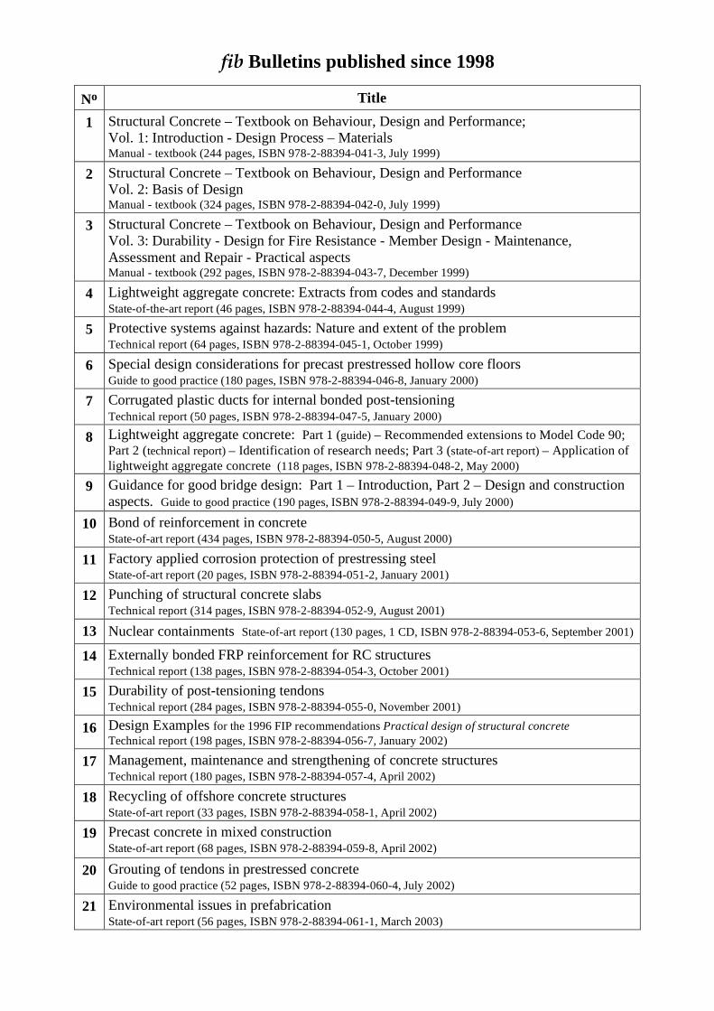
fib Bulletins published since 1998
No Title 1 Structural Concrete – Textbook on Behaviour, Design and Performance;
Vol. 1: Introduction - Design Process – Materials Manual - textbook (244 pages, ISBN 978-2-88394-041-3, July 1999)
2 Structural Concrete – Textbook on Behaviour, Design and Performance Vol. 2: Basis of Design Manual - textbook (324 pages, ISBN 978-2-88394-042-0, July 1999)
3 Structural Concrete – Textbook on Behaviour, Design and Performance Vol. 3: Durability - Design for Fire Resistance - Member Design - Maintenance, Assessment and Repair - Practical aspects Manual - textbook (292 pages, ISBN 978-2-88394-043-7, December 1999)
4 Lightweight aggregate concrete: Extracts from codes and standards State-of-the-art report (46 pages, ISBN 978-2-88394-044-4, August 1999)
5 Protective systems against hazards: Nature and extent of the problem Technical report (64 pages, ISBN 978-2-88394-045-1, October 1999)
6 Special design considerations for precast prestressed hollow core floors Guide to good practice (180 pages, ISBN 978-2-88394-046-8, January 2000)
7 Corrugated plastic ducts for internal bonded post-tensioning Technical report (50 pages, ISBN 978-2-88394-047-5, January 2000)
8 Lightweight aggregate concrete: Part 1 (guide) – Recommended extensions to Model Code 90; Part 2 (technical report) – Identification of research needs; Part 3 (state-of-art report) – Application of lightweight aggregate concrete (118 pages, ISBN 978-2-88394-048-2, May 2000)
9 Guidance for good bridge design: Part 1 – Introduction, Part 2 – Design and construction aspects. Guide to good practice (190 pages, ISBN 978-2-88394-049-9, July 2000)
10 Bond of reinforcement in concrete State-of-art report (434 pages, ISBN 978-2-88394-050-5, August 2000)
11 Factory applied corrosion protection of prestressing steel State-of-art report (20 pages, ISBN 978-2-88394-051-2, January 2001)
12 Punching of structural concrete slabs Technical report (314 pages, ISBN 978-2-88394-052-9, August 2001)
13 Nuclear containments State-of-art report (130 pages, 1 CD, ISBN 978-2-88394-053-6, September 2001)
14 Externally bonded FRP reinforcement for RC structures Technical report (138 pages, ISBN 978-2-88394-054-3, October 2001)
15 Durability of post-tensioning tendons Technical report (284 pages, ISBN 978-2-88394-055-0, November 2001)
16 Design Examples for the 1996 FIP recommendations Practical design of structural concrete Technical report (198 pages, ISBN 978-2-88394-056-7, January 2002)
17 Management, maintenance and strengthening of concrete structures Technical report (180 pages, ISBN 978-2-88394-057-4, April 2002)
18 Recycling of offshore concrete structures State-of-art report (33 pages, ISBN 978-2-88394-058-1, April 2002)
19 Precast concrete in mixed construction State-of-art report (68 pages, ISBN 978-2-88394-059-8, April 2002)
20 Grouting of tendons in prestressed concrete Guide to good practice (52 pages, ISBN 978-2-88394-060-4, July 2002)
21 Environmental issues in prefabrication State-of-art report (56 pages, ISBN 978-2-88394-061-1, March 2003)
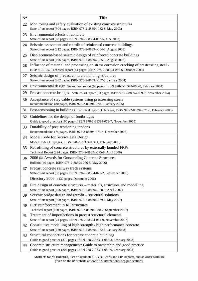
No Title
22 Monitoring and safety evaluation of existing concrete structures State-of-art report (304 pages, ISBN 978-2-88394-062-8, May 2003)
23 Environmental effects of concrete State-of-art report (68 pages, ISBN 978-2-88394-063-5, June 2003)
24 Seismic assessment and retrofit of reinforced concrete buildings State-of-art report (312 pages, ISBN 978-2-88394-064-2, August 2003)
25 Displacement-based seismic design of reinforced concrete buildings State-of-art report (196 pages, ISBN 978-2-88394-065-9, August 2003)
26 Influence of material and processing on stress corrosion cracking of prestressing steel - case studies. Technical report (44 pages, ISBN 978-2-88394-066-6, October 2003)
27 Seismic design of precast concrete building structures State-of-art report (262 pages, ISBN 978-2-88394-067-3, January 2004)
28 Environmental design State-of-art report (86 pages, ISBN 978-2-88394-068-0, February 2004)
29 Precast concrete bridges State-of-art report (83 pages, ISBN 978-2-88394-069-7, November 2004)
30 Acceptance of stay cable systems using prestressing steels Recommendation (80 pages, ISBN 978-2-88394-070-3, January 2005)
31 Post-tensioning in buildings Technical report (116 pages, ISBN 978-2-88394-071-0, February 2005)
32 Guidelines for the design of footbridges Guide to good practice (160 pages, ISBN 978-2-88394-072-7, November 2005)
33 Durability of post-tensioning tendons Recommendation (74 pages, ISBN 978-2-88394-073-4, December 2005)
34 Model Code for Service Life Design Model Code (116 pages, ISBN 978-2-88394-074-1, February 2006)
35 Retrofitting of concrete structures by externally bonded FRPs. Technical Report (224 pages, ISBN 978-2-88394-075-8, April 2006)
36 2006 fib Awards for Outstanding Concrete Structures Bulletin (40 pages, ISBN 978-2-88394-076-5, May 2006)
37 Precast concrete railway track systems State-of-art report (38 pages, ISBN 978-2-88394-077-2, September 2006)
Directory 2006 (130 pages, December 2006)
38 Fire design of concrete structures – materials, structures and modelling State-of-art report (106 pages, ISBN 978-2-88394-078-9, April 2007)
39 Seismic bridge design and retrofit – structural solutions State-of-art report (300 pages, ISBN 978-2-88394-079-6, May 2007)
40 FRP reinforcement in RC structures Technical report (160 pages, ISBN 978-2-88394-080-2, September 2007)
41 Treatment of imperfections in precast structural elements State-of-art report (74 pages, ISBN 978-2-88394-081-9, November 2007)
42 Constitutive modelling of high strength / high performance concrete State-of-art report (130 pages, ISBN 978-2-88394-082-6, January 2008)
43 Structural connections for precast concrete buildings Guide to good practice (370 pages, ISBN 978-2-88394-083-3, February 2008)
44 Concrete structure management: Guide to ownership and good practice Guide to good practice (208 pages, ISBN 978-2-88394-084-0, February 2008)
Abstracts for fib Bulletins, lists of available CEB Bulletins and FIP Reports, and an order form are
given on the fib website at www.fib-international.org/publications.