Embed Size (px)
Citation preview
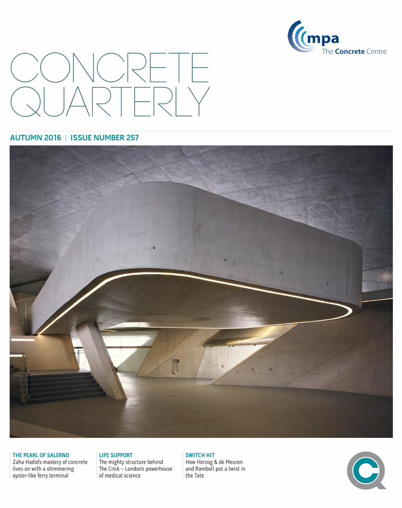
CONCRETE QUARTERLYAUTUMN 2016 | ISSUE NUMBER 257
SWITCH HITHow Herzog & de Meuron and Ramboll put a twist in the Tate
THE PEARL OF SALERNOZaha Hadid’s mastery of concrete lives on with a shimmering oyster-like ferry terminal
LIFE SUPPORTThe mighty structure behind The Crick – London’s powerhouse of medical science
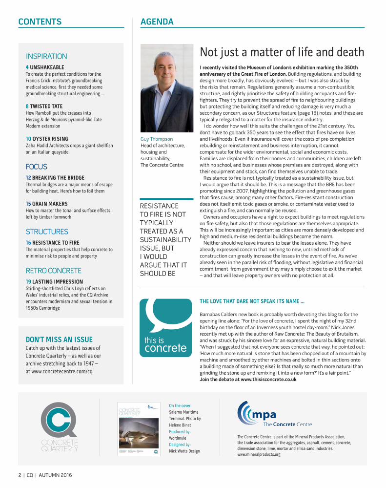
AGENDA
Not just a matter of life and deathI recently visited the Museum of London’s exhibition marking the 350th anniversary of the Great Fire of London. Building regulations, and building design more broadly, has obviously evolved – but I was also struck by the risks that remain. Regulations generally assume a non-combustible structure, and rightly prioritise the safety of building occupants and fire-fighters. They try to prevent the spread of fire to neighbouring buildings, but protecting the building itself and reducing damage is very much a secondary concern, as our Structures feature (page 16) notes, and these are typically relegated to a matter for the insurance industry.
I do wonder how well this suits the challenges of the 21st century. You don’t have to go back 350 years to see the effect that fires have on lives and livelihoods. Even if insurance will cover the costs of pre-completion rebuilding or reinstatement and business interruption, it cannot compensate for the wider environmental, social and economic costs. Families are displaced from their homes and communities, children are left with no school, and businesses whose premises are destroyed, along with their equipment and stock, can find themselves unable to trade.
Resistance to fire is not typically treated as a sustainability issue, but I would argue that it should be. This is a message that the BRE has been promoting since 2007, highlighting the pollution and greenhouse gases that fires cause, among many other factors. Fire-resistant construction does not itself emit toxic gases or smoke, or contaminate water used to extinguish a fire, and can normally be reused.
Owners and occupiers have a right to expect buildings to meet regulations on fire safety, but also that those regulations are themselves appropriate. This will be increasingly important as cities are more densely developed and high and medium-rise residential buildings become the norm.
Neither should we leave insurers to bear the losses alone. They have already expressed concern that rushing to new, untried methods of construction can greatly increase the losses in the event of fire. As we’ve already seen in the parallel risk of flooding, without legislative and financial commitment from government they may simply choose to exit the market – and that will leave property owners with no protection at all.
RESISTANCE TO FIRE IS NOT TYPICALLY TREATED AS A SUSTAINABILITY ISSUE, BUT I WOULD ARGUE THAT IT SHOULD BE
Barnabas Calder’s new book is probably worth devoting this blog to for the opening line alone: “For the love of concrete, I spent the night of my 32nd birthday on the floor of an Inverness youth hostel day-room.” Nick Jones recently met up with the author of Raw Concrete: The Beauty of Brutalism, and was struck by his sincere love for an expressive, natural building material. “When I suggested that not everyone sees concrete that way, he pointed out: ‘How much more natural is stone that has been chopped out of a mountain by machine and smoothed by other machines and bolted in thin sections onto a building made of something else? Is that really so much more natural than grinding the stone up and remixing it into a new form?’ It’s a fair point.”Join the debate at www.thisisconcrete.co.uk
THE LOVE THAT DARE NOT SPEAK ITS NAME …
The Concrete Centre is part of the Mineral Products Association, the trade association for the aggregates, asphalt, cement, concrete, dimension stone, lime, mortar and silica sand industries. www.mineralproducts.org
On the cover: Salerno Maritime Terminal. Photo by Hélène BinetProduced by: WordmuleDesigned by: Nick Watts Design
CONTENTS
INSPIRATION4 UNSHAKEABLETo create the perfect conditions for the Francis Crick Institute’s groundbreaking medical science, first they needed some groundbreaking structural engineering …
8 TWISTED TATE How Ramboll put the creases into Herzog & de Meuron’s pyramid-like Tate Modern extension
10 OYSTER RISINGZaha Hadid Architects drops a giant shellfish on an Italian quayside
FOCUS12 BREAKING THE BRIDGEThermal bridges are a major means of escape for building heat. Here’s how to foil them
15 GRAIN MAKERSHow to master the tonal and surface effects left by timber formwork
STRUCTURES16 RESISTANCE TO FIREThe material properties that help concrete to minimise risk to people and property
RETRO CONCRETE19 LASTING IMPRESSIONStirling-shortlisted Chris Loyn reflects on Wales’ industrial relics, and the CQ Archive encounters modernism and sexual tension in 1960s Cambridge
DON’T MISS AN ISSUECatch up with the lastest issues of Concrete Quarterly – as well as our archive stretching back to 1947 – at www.concretecentre.com/cq
2 | CQ | AUTUMN 2016
Guy ThompsonHead of architecture, housing and sustainability, The Concrete Centre
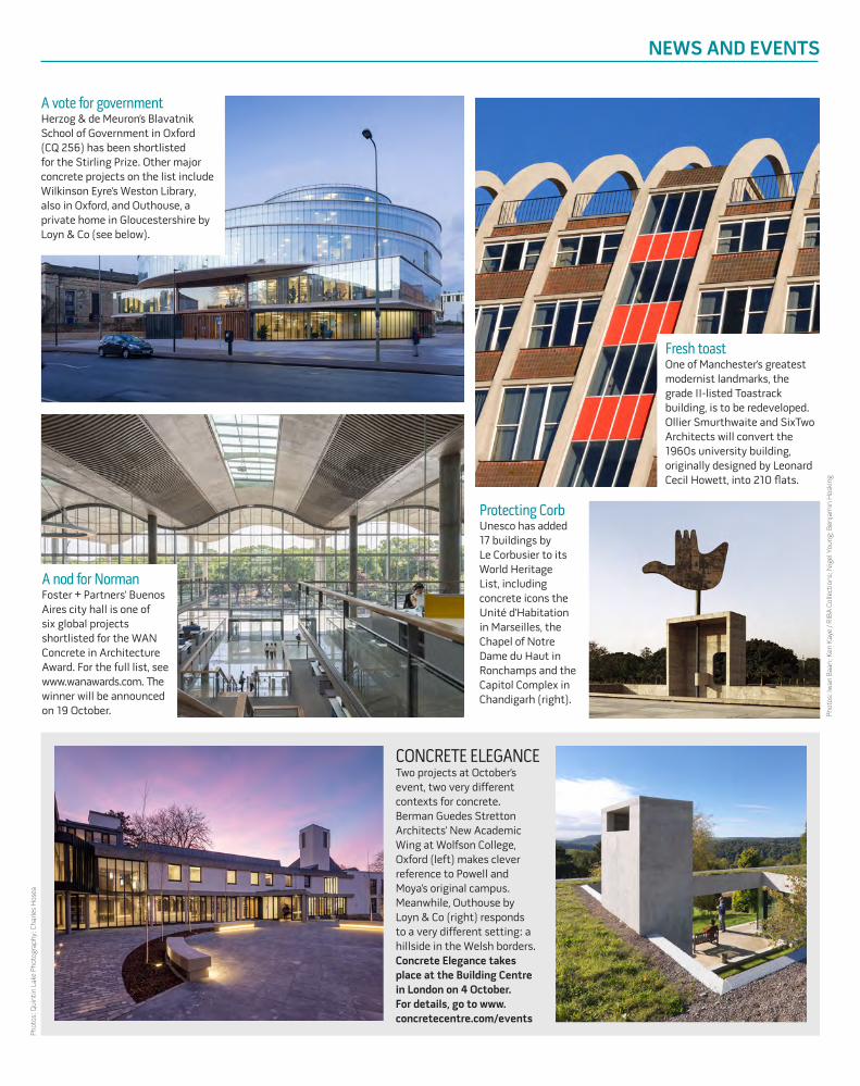
A vote for governmentHerzog & de Meuron’s Blavatnik School of Government in Oxford (CQ 256) has been shortlisted for the Stirling Prize. Other major concrete projects on the list include Wilkinson Eyre’s Weston Library, also in Oxford, and Outhouse, a private home in Gloucestershire by Loyn & Co (see below).
NEWS AND EVENTS
A nod for Norman Foster + Partners’ Buenos Aires city hall is one of six global projects shortlisted for the WAN Concrete in Architecture Award. For the full list, see www.wanawards.com. The winner will be announced on 19 October.
Protecting CorbUnesco has added 17 buildings by Le Corbusier to its World Heritage List, including concrete icons the Unité d’Habitation in Marseilles, the Chapel of Notre Dame du Haut in Ronchamps and the Capitol Complex in Chandigarh (right).
CONCRETE ELEGANCETwo projects at October’s event, two very different contexts for concrete. Berman Guedes Stretton Architects’ New Academic Wing at Wolfson College, Oxford (left) makes clever reference to Powell and Moya’s original campus. Meanwhile, Outhouse by Loyn & Co (right) responds to a very different setting: a hillside in the Welsh borders.Concrete Elegance takes place at the Building Centre in London on 4 October. For details, go to www.concretecentre.com/events
Phot
os: Q
uint
in L
ake
Phot
ogra
phy;
Cha
rles
Hos
ea
Phot
os: I
wan
Baa
n; K
en K
aye
/ RIB
A C
olle
ctio
ns; N
igel
You
ng; B
enja
min
Hos
king
Fresh toast One of Manchester’s greatest modernist landmarks, the grade II-listed Toastrack building, is to be redeveloped. Ollier Smurthwaite and SixTwo Architects will convert the 1960s university building, originally designed by Leonard Cecil Howett, into 210 flats.
4 | CQ | AUTUMN 2016
EVEN COMPARED TO THE ROYAL LONDON OR BARTS, WHICH BOTH FINISHED RECENTLY, ANOTHER 7-8% OF THE BUDGET WAS SPENT ON SERVICES HERE
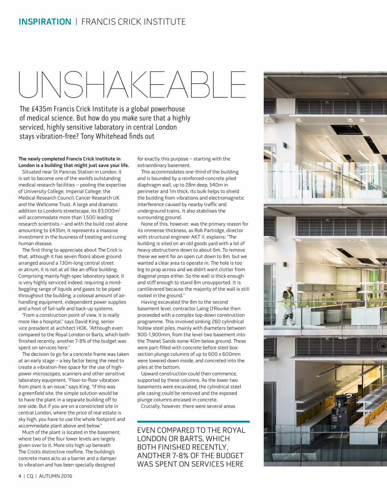
UNSHAKEABLEThe £435m Francis Crick Institute is a global powerhouse of medical science. But how do you make sure that a highly serviced, highly sensitive laboratory in central London stays vibration-free? Tony Whitehead finds out
INSPIRATION | FRANCIS CRICK INSTITUTE
The newly completed Francis Crick Institute in London is a building that might just save your life.
Situated near St Pancras Station in London, it is set to become one of the world’s outstanding medical research facilities – pooling the expertise of University College, Imperial College, the Medical Research Council, Cancer Research UK and the Wellcome Trust. A large and dramatic addition to London’s streetscape, its 83,000m2 will accommodate more than 1,500 leading research scientists – and with the build cost alone amounting to £435m, it represents a massive investment in the business of treating and curing human disease.
The first thing to appreciate about The Crick is that, although it has seven floors above ground arranged around a 130m-long central street or atrium, it is not at all like an office building. Comprising mainly high-spec laboratory space, it is very highly serviced indeed, requiring a mind-boggling range of liquids and gases to be piped throughout the building, a colossal amount of air-handling equipment, independent power supplies and a host of fail-safe and back-up systems.
“From a construction point of view, it is really more like a hospital,” says David King, senior vice president at architect HOK. “Although even compared to the Royal London or Barts, which both finished recently, another 7-8% of the budget was spent on services here.”
The decision to go for a concrete frame was taken at an early stage – a key factor being the need to create a vibration-free space for the use of high-power microscopes, scanners and other sensitive laboratory equipment. “Floor-to-floor vibration from plant is an issue,” says King. “If this was a greenfield site, the simple solution would be to have the plant in a separate building off to one side. But if you are on a constricted site in central London, where the price of real estate is sky high, you have to use the whole footprint and accommodate plant above and below.”
Much of the plant is located in the basement, where two of the four lower levels are largely given over to it. More sits high up beneath The Crick’s distinctive roofline. The building’s concrete mass acts as a barrier and a damper to vibration and has been specially designed
for exactly this purpose – starting with the extraordinary basement.
This accommodates one-third of the building and is bounded by a reinforced-concrete piled diaphragm wall, up to 28m deep, 540m in perimeter and 1m thick. Its bulk helps to shield the building from vibrations and electromagnetic interference caused by nearby traffic and underground trains. It also stabilises the surrounding ground.
None of this, however, was the primary reason for its immense thickness, as Rob Partridge, director with structural engineer AKT II, explains: “The building is sited on an old goods yard with a lot of heavy obstructions down to about 6m. To remove these we went for an open cut down to 8m, but we wanted a clear area to operate in. The hole is too big to prop across and we didn’t want clutter from diagonal props either. So the wall is thick enough and stiff enough to stand 8m unsupported. It is cantilevered because the majority of the wall is still rooted in the ground.”
Having excavated the 8m to the second basement level, contractor Laing O’Rourke then proceeded with a complex top-down construction programme. This involved sinking 260 cylindrical hollow steel piles, mainly with diameters between 900-1,900mm, from the level-two basement into the Thanet Sands some 40m below ground. These were part-filled with concrete before steel box-section plunge columns of up to 600 x 600mm were lowered down inside, and concreted into the piles at the bottom.
Upward construction could then commence, supported by these columns. As the lower two basements were excavated, the cylindrical steel pile casing could be removed and the exposed plunge columns encased in concrete.
Crucially, however, there were several areas
Phot
o:
Phot
o: W
ellc
ome
Trus
t
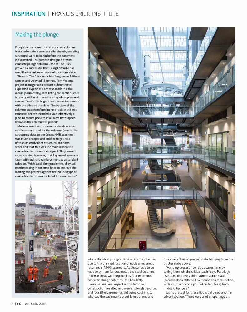
Making the plunge
Plunge columns are concrete or steel columns installed within a concrete pile, thereby enabling structural work to begin before the basement is excavated. The purpose-designed precast-concrete plunge columns used at The Crick proved so successful that Laing O’Rourke has used the technique on several occasions since.
Those at The Crick were 14m long, some 800mm square, and weighed 15 tonnes. Tom Mullens, project manager with precast subcontractor Expanded, explains: “Each was made in a flat mould [horizontally] with lifting connections cast in, along with an impressive array of couplers and connection details to get the columns to connect with the pile and the slabs. The bottom of the columns was chamfered to help it sit in the wet concrete, and we included a void, effectively a pipe, to ensure pockets of air were not trapped below as the column was placed.”
Mullens says the non-ferrous stainless steel reinforcement used for the columns (needed for structures close to the Crick’s NMR scanners) was much cheaper and quicker to get hold of than an equivalent structural stainless steel, and that this was the main reason the concrete columns were designed. They proved so successful, however, that Expanded now uses them with ordinary reinforcement as a standard solution. “With steel plunge columns, they still need encasing in concrete later to improve the loading and protect against fire, so this type of concrete column saves a lot of time and mess.”
6 | CQ | AUTUMN 2016
INSPIRATION | FRANCIS CRICK INSTITUTE
where the steel plunge columns could not be used due to the planned location of nuclear magnetic resonance (NMR) scanners. As these have to be kept away from ferrous metal, the steel columns in these areas were replaced by four enormous concrete plunge columns (see box, left).
Another unusual aspect of the top-down construction resulted in basement levels zero, two and four (the basement slab) being cast in situ, whereas the basement’s plant levels of one and
three were thinner precast slabs hanging from the thicker slabs above.
“Hanging precast floor slabs saves time by taking them off the critical path,” says Partridge. “We used relatively thin 175mm lattice slabs [precast slabs stiffened by means of a steel lattice, with in-situ concrete poured on top] hung from mid-grid hangers.”
Using precast for these floors delivered another advantage too: “There were a lot of openings on
OPPOSITE The floors are constructed from 400mm-thick precast lattice slabs
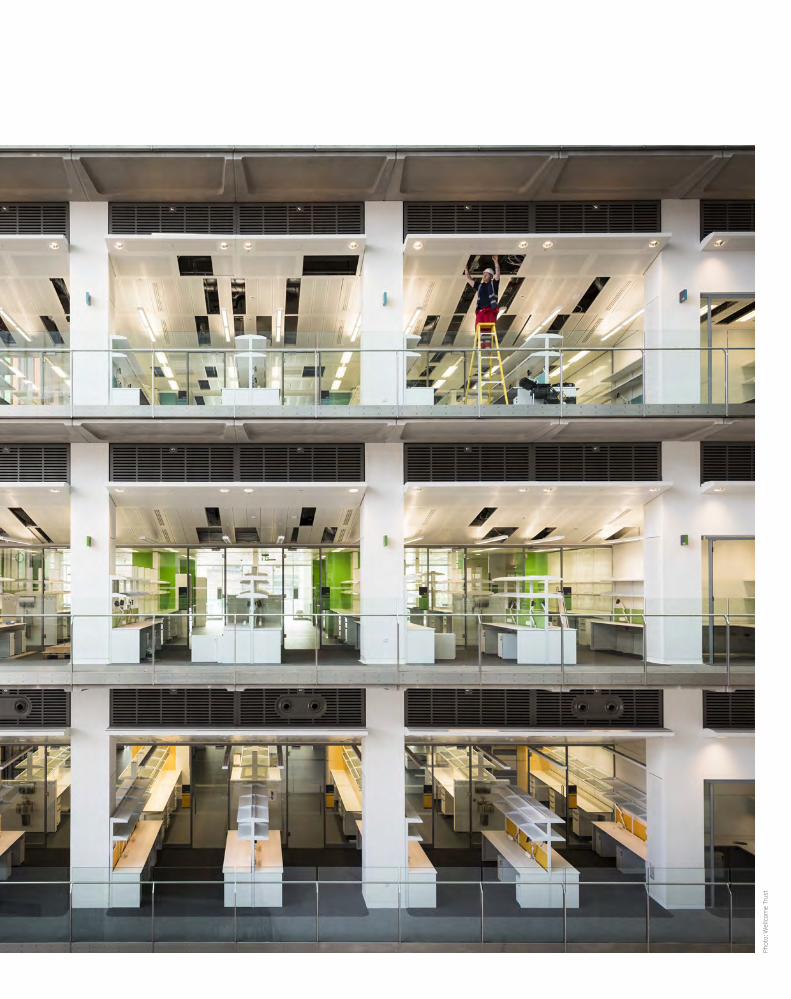
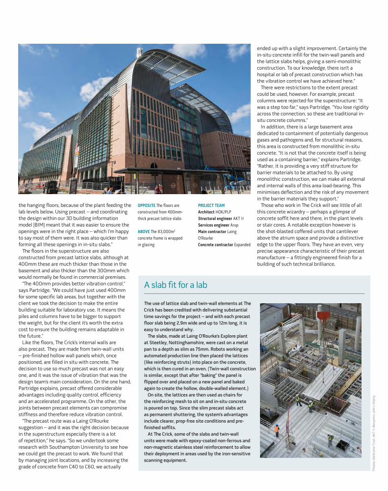
ABOVE The 83,000m2 concrete frame is wrapped in glazing
PROJECT TEAMArchitect HOK/PLPStructural engineer AKT IIServices engineer ArupMain contractor Laing O’RourkeConcrete contractor Expanded
A slab fit for a lab
The use of lattice slab and twin-wall elements at The Crick has been credited with delivering substantial time savings for the project – and with each precast floor slab being 2.9m wide and up to 12m long, it is easy to understand why.
The slabs, made at Laing O’Rourke’s Explore plant at Steetley, Nottinghamshire, were cast on a metal pan to a depth as slim as 75mm. Robots working an automated production line then placed the lattices (like reinforcing struts) into place on the concrete, which is then cured in an oven. (Twin-wall construction is similar, except that after “baking” the panel is flipped over and placed on a new panel and baked again to create the hollow, double-walled element.)
On site, the lattices are then used as chairs for the reinforcing mesh to sit on and in-situ concrete is poured on top. Since the slim precast slabs act as permanent shuttering, the system’s advantages include clearer, prop-free site conditions and pre-finished soffits.
At The Crick, some of the slabs and twin-wall units were made with epoxy-coated non-ferrous and non-magnetic stainless steel reinforcement to allow their deployment in areas used by the iron-sensitive scanning equipment.
the hanging floors, because of the plant feeding the lab levels below. Using precast – and coordinating the design within our 3D building information model [BIM] meant that it was easier to ensure the openings were in the right place – which I’m happy to say most of them were. It was also quicker than forming all these openings in in-situ slabs.”
The floors in the superstructure are also constructed from precast lattice slabs, although at 400mm these are much thicker than those in the basement and also thicker than the 300mm which would normally be found in commercial premises.
“The 400mm provides better vibration control,” says Partridge. “We could have just used 400mm for some specific lab areas, but together with the client we took the decision to make the entire building suitable for laboratory use. It means the piles and columns have to be bigger to support the weight, but for the client it’s worth the extra cost to ensure the building remains adaptable in the future.”
Like the floors, The Crick’s internal walls are also precast. They are made from twin-wall units – pre-finished hollow wall panels which, once positioned, are filled in situ with concrete. The decision to use so much precast was not an easy one, and it was the issue of vibration that was the design team’s main consideration. On the one hand, Partridge explains, precast offered considerable advantages including quality control, efficiency and an accelerated programme. On the other, the joints between precast elements can compromise stiffness and therefore reduce vibration control.
“The precast route was a Laing O’Rourke suggestion – and it was the right decision because in the superstructure especially there is a lot of repetition,” he says. “So we undertook some research with Southampton University to see how we could get the precast to work. We found that by managing joint locations, and by increasing the grade of concrete from C40 to C60, we actually
ended up with a slight improvement. Certainly the in-situ concrete infill for the twin-wall panels and the lattice slabs helps, giving a semi-monolithic construction. To our knowledge, there isn’t a hospital or lab of precast construction which has the vibration control we have achieved here.”
There were restrictions to the extent precast could be used, however. For example, precast columns were rejected for the superstructure: “It was a step too far,” says Partridge. “You lose rigidity across the connection, so these are traditional in-situ concrete columns.”
In addition, there is a large basement area dedicated to containment of potentially dangerous gases and pathogens and, for structural reasons, this area is constructed from monolithic in-situ concrete. “It is not that the concrete itself is being used as a containing barrier,” explains Partridge. “Rather, it is providing a very stiff structure for barrier materials to be attached to. By using monolithic construction, we can make all external and internal walls of this area load-bearing. This minimises deflection and the risk of any movement in the barrier materials they support.”
Those who work in The Crick will see little of all this concrete wizardry – perhaps a glimpse of concrete soffit here and there, in the plant levels or stair cores. A notable exception however is the shot-blasted coffered units that cantilever above the atrium space and provide a distinctive edge to the upper floors. They have an even, very precise appearance characteristic of their precast manufacture – a fittingly engineered finish for a building of such technical brilliance.
Phot
os: W
ellc
ome
Trus
t; A
KT
II; B
enja
min
Joh
n / A
lam
y

8 | CQ | AUTUMN 2016
In solving the structural riddle of Tate Modern’s new Switch House, Ramboll has created some extraordinary concrete spaces, writes Nick Jones
From its turbine hall to its subterranean oil tank galleries, Herzog & de Meuron’s Tate Modern has always made ingenious use of unlikely spaces. Now the first new-build structure has been built on the site – a 65m-high twisting brick-clad pyramid connected to the rear of the former power station. In some ways, it is the most unlikely space of the lot.
If you had the choice, you probably wouldn’t build anything on this site at all. The eastern end of Tate Modern still houses a UK Power Network facility, which means the main cable that drives the City runs directly below. Things don’t get much better above ground. Constrained on two sides by the power station and Richard Rogers’ luxury Neo Bankside development, and above by rights to light and viewing corridors to St Paul’s, there was only a small envelope in which to fit a building – and even this was directly on top of the underground oil tanks.
But with visitor numbers topping 5 million a year and a collection that had expanded massively to include installations, videos and audio works, Tate Modern desperately needed more space. So Herzog & de Meuron, the architect behind the original redevelopment, began to weave a building through Bankside’s tightly regulated airspace. Starting from a square footprint, the architects pulled out the corners and extruded upwards, tilting the form into the space available. The result was a series of slanting elevations, each with a sharp crease where it met the vertical. The whole would be wrapped in a perforated veil of red brick, which would filter sunlight by day and glow from within by night. The overall effect would be both a coherent extension to the original building and a robust London icon in its own right.
In fact, the only problem with the tower – known as the Switch House – was how to build it. If the architects’ approach was to design from the outside
INSPIRATION | TATE MODERN
in, then structural engineer Ramboll had to work out how to do the same in the opposite direction, ending with the installation of the brick façade to a tolerance of +-2mm. From the start, it was clear that concrete would be key to making this unique form stand up. “We’ve got pretty much every known form of concrete construction in this building,” says Martin Burden, director of Ramboll.
Chief among these are two jump-form concrete cores – it quickly became clear that one core would not be enough. “Because the elevations are all sloping in, you get these massive horizontal forces – they’re always wanting to push the building in,” says Philip Wilkinson, associate at Ramboll. To take account of the twisting effect of the building form, the huge main core is positioned off-centre. It holds four passenger lifts, two emergency stairs and a mighty 15m-long x 5m-high lift for transporting artworks. The smaller core rises to the fourth floor and contains four passenger lifts.
Moving outwards from the cores, the generous 1,500mm-deep floor plates are formed of long-span, in-situ concrete ribs, which support both an in-situ slab and precast soffits. Services are located in a 500mm raised floor, dropping down through carefully coordinated holes in the rib beams. Cooling coils were cast into the soffit panels to exploit the concrete’s thermal mass. This system, which uses water from two bore holes in the ground, is also key to the building’s iconic form, as it meant that the roofline was free from chiller plant.
TWISTED TATE
WE’VE GOT PRETTY MUCH EVERY KNOWN FORM OF CONCRETE CONSTRUCTION IN THIS BUILDING
There are strikingly few internal columns – just three up to the sixth floor and six on the upper storeys – the structure instead relying on an immense precast-concrete exoskeleton, which transfers loads down into a network of 800 piles, crammed in every available space around the existing groundworks. Because of the building’s cranked form, the frame is irregular, which meant that more than 40 different moulds were needed for the perimeter columns. These were cast in a
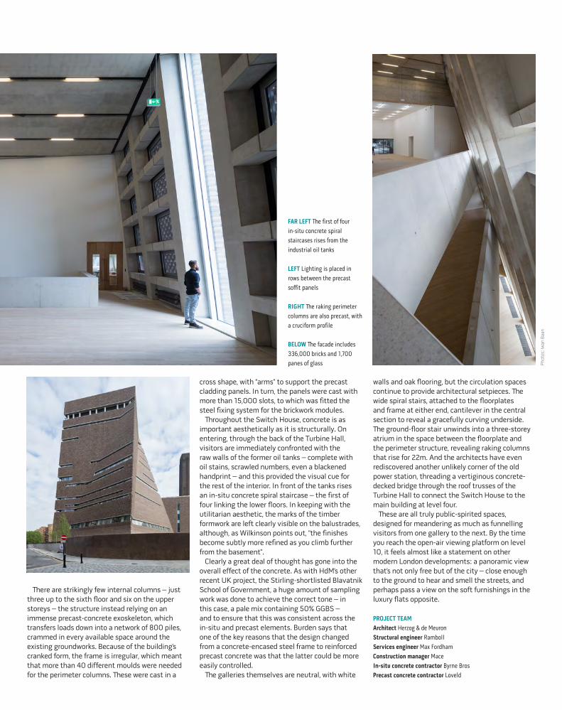
FAR LEFT The first of four in-situ concrete spiral staircases rises from the industrial oil tanks
LEFT Lighting is placed in rows between the precast soffit panels
RIGHT The raking perimeter columns are also precast, with a cruciform profile
BELOW The facade includes 336,000 bricks and 1,700 panes of glass Ph
otos
: Iw
an B
aan
walls and oak flooring, but the circulation spaces continue to provide architectural setpieces. The wide spiral stairs, attached to the floorplates and frame at either end, cantilever in the central section to reveal a gracefully curving underside. The ground-floor stair unwinds into a three-storey atrium in the space between the floorplate and the perimeter structure, revealing raking columns that rise for 22m. And the architects have even rediscovered another unlikely corner of the old power station, threading a vertiginous concrete-decked bridge through the roof trusses of the Turbine Hall to connect the Switch House to the main building at level four.
These are all truly public-spirited spaces, designed for meandering as much as funnelling visitors from one gallery to the next. By the time you reach the open-air viewing platform on level 10, it feels almost like a statement on other modern London developments: a panoramic view that’s not only free but of the city – close enough to the ground to hear and smell the streets, and perhaps pass a view on the soft furnishings in the luxury flats opposite.
PROJECT TEAM Architect Herzog & de MeuronStructural engineer RambollServices engineer Max FordhamConstruction manager MaceIn-situ concrete contractor Byrne BrosPrecast concrete contractor Loveld
cross shape, with “arms” to support the precast cladding panels. In turn, the panels were cast with more than 15,000 slots, to which was fitted the steel fixing system for the brickwork modules.
Throughout the Switch House, concrete is as important aesthetically as it is structurally. On entering, through the back of the Turbine Hall, visitors are immediately confronted with the raw walls of the former oil tanks – complete with oil stains, scrawled numbers, even a blackened handprint – and this provided the visual cue for the rest of the interior. In front of the tanks rises an in-situ concrete spiral staircase – the first of four linking the lower floors. In keeping with the utilitarian aesthetic, the marks of the timber formwork are left clearly visible on the balustrades, although, as Wilkinson points out, “the finishes become subtly more refined as you climb further from the basement”.
Clearly a great deal of thought has gone into the overall effect of the concrete. As with HdM’s other recent UK project, the Stirling-shortlisted Blavatnik School of Government, a huge amount of sampling work was done to achieve the correct tone – in this case, a pale mix containing 50% GGBS – and to ensure that this was consistent across the in-situ and precast elements. Burden says that one of the key reasons that the design changed from a concrete-encased steel frame to reinforced precast concrete was that the latter could be more easily controlled.
The galleries themselves are neutral, with white
10 | CQ | AUTUMN 2016
Beneath its ceramic shell, Zaha Hadid’s first posthumous work recalls some of her finest concrete projects, writes Pamela Buxton
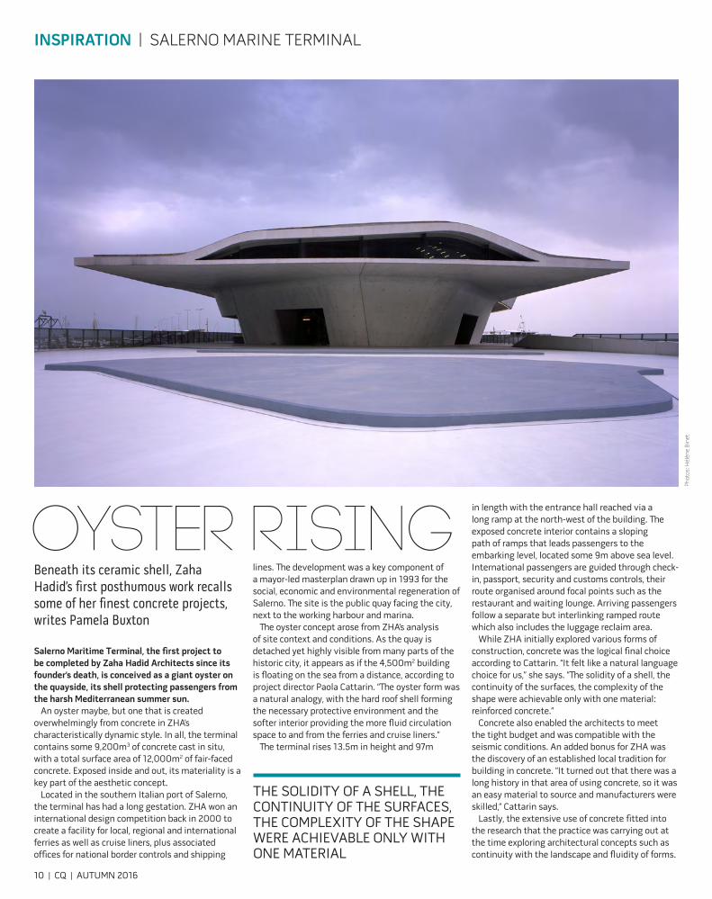
Salerno Maritime Terminal, the first project to be completed by Zaha Hadid Architects since its founder’s death, is conceived as a giant oyster on the quayside, its shell protecting passengers from the harsh Mediterranean summer sun.
An oyster maybe, but one that is created overwhelmingly from concrete in ZHA’s characteristically dynamic style. In all, the terminal contains some 9,200m3 of concrete cast in situ, with a total surface area of 12,000m2 of fair-faced concrete. Exposed inside and out, its materiality is a key part of the aesthetic concept.
Located in the southern Italian port of Salerno, the terminal has had a long gestation. ZHA won an international design competition back in 2000 to create a facility for local, regional and international ferries as well as cruise liners, plus associated offices for national border controls and shipping
lines. The development was a key component of a mayor-led masterplan drawn up in 1993 for the social, economic and environmental regeneration of Salerno. The site is the public quay facing the city, next to the working harbour and marina.
The oyster concept arose from ZHA’s analysis of site context and conditions. As the quay is detached yet highly visible from many parts of the historic city, it appears as if the 4,500m2 building is floating on the sea from a distance, according to project director Paola Cattarin. “The oyster form was a natural analogy, with the hard roof shell forming the necessary protective environment and the softer interior providing the more fluid circulation space to and from the ferries and cruise liners.”
The terminal rises 13.5m in height and 97m
INSPIRATION | SALERNO MARINE TERMINAL
in length with the entrance hall reached via a long ramp at the north-west of the building. The exposed concrete interior contains a sloping path of ramps that leads passengers to the embarking level, located some 9m above sea level. International passengers are guided through check-in, passport, security and customs controls, their route organised around focal points such as the restaurant and waiting lounge. Arriving passengers follow a separate but interlinking ramped route which also includes the luggage reclaim area.
While ZHA initially explored various forms of construction, concrete was the logical final choice according to Cattarin. “It felt like a natural language choice for us,” she says. “The solidity of a shell, the continuity of the surfaces, the complexity of the shape were achievable only with one material: reinforced concrete.”
Concrete also enabled the architects to meet the tight budget and was compatible with the seismic conditions. An added bonus for ZHA was the discovery of an established local tradition for building in concrete. “It turned out that there was a long history in that area of using concrete, so it was an easy material to source and manufacturers were skilled,” Cattarin says.
Lastly, the extensive use of concrete fitted into the research that the practice was carrying out at the time exploring architectural concepts such as continuity with the landscape and fluidity of forms.
OYSTER RISING
THE SOLIDITY OF A SHELL, THE CONTINUITY OF THE SURFACES, THE COMPLEXITY OF THE SHAPE WERE ACHIEVABLE ONLY WITH ONE MATERIAL
Phot
os: H
élèn
e Bi
net
Due to its fluidity, self-compacting concrete was considered. However the architects decided that in-situ concrete, using traditional plywood and steel formwork, was able to meet their stringent requirements for almost all of the project. This was a challenge for the contractor, given the dynamic form of the design and required extensive testing and mock-ups. “The geometry was unusual, and also the level of quality we wanted wasn’t standard … The contractors had to use their creativity to find the best way to build the formwork,” says Cattarin.
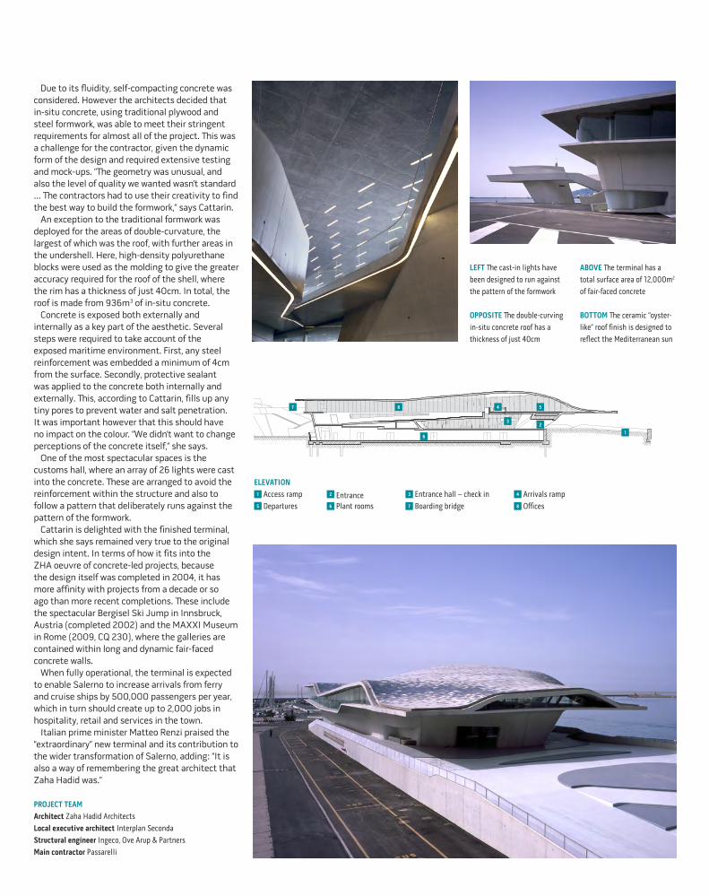
An exception to the traditional formwork was deployed for the areas of double-curvature, the largest of which was the roof, with further areas in the undershell. Here, high-density polyurethane blocks were used as the molding to give the greater accuracy required for the roof of the shell, where the rim has a thickness of just 40cm. In total, the roof is made from 936m3 of in-situ concrete.
Concrete is exposed both externally and internally as a key part of the aesthetic. Several steps were required to take account of the exposed maritime environment. First, any steel reinforcement was embedded a minimum of 4cm from the surface. Secondly, protective sealant was applied to the concrete both internally and externally. This, according to Cattarin, fills up any tiny pores to prevent water and salt penetration. It was important however that this should have no impact on the colour. “We didn’t want to change perceptions of the concrete itself,” she says.
One of the most spectacular spaces is the customs hall, where an array of 26 lights were cast into the concrete. These are arranged to avoid the reinforcement within the structure and also to follow a pattern that deliberately runs against the pattern of the formwork.
Cattarin is delighted with the finished terminal, which she says remained very true to the original design intent. In terms of how it fits into the ZHA oeuvre of concrete-led projects, because the design itself was completed in 2004, it has more affinity with projects from a decade or so ago than more recent completions. These include the spectacular Bergisel Ski Jump in Innsbruck, Austria (completed 2002) and the MAXXI Museum in Rome (2009, CQ 230), where the galleries are contained within long and dynamic fair-faced concrete walls.
When fully operational, the terminal is expected to enable Salerno to increase arrivals from ferry and cruise ships by 500,000 passengers per year, which in turn should create up to 2,000 jobs in hospitality, retail and services in the town.
Italian prime minister Matteo Renzi praised the “extraordinary” new terminal and its contribution to the wider transformation of Salerno, adding: “It is also a way of remembering the great architect that Zaha Hadid was.”
PROJECT TEAM Architect Zaha Hadid ArchitectsLocal executive architect Interplan SecondaStructural engineer Ingeco, Ove Arup & Partners Main contractor Passarelli
LEFT The cast-in lights have been designed to run against the pattern of the formwork
OPPOSITE The double-curving in-situ concrete roof has a thickness of just 40cm
ABOVE The terminal has a total surface area of 12,000m2 of fair-faced concrete
BOTTOM The ceramic “oyster-like” roof finish is designed to reflect the Mediterranean sun
ELEVATION1 Access ramp 2 Entrance 3 Entrance hall – check in 4 Arrivals ramp5 Departures 6 Plant rooms 7 Boarding bridge 8 Offices
32
8
6
5
1
47

12 | CQ | AUTUMN 2016
FOCUS | THERMAL BRIDGING
BREAKING THE BRIDGE Thermal bridging can account for up to 35% of heat loss from a building. Tom De Saulles outlines the best ways to foil this means of escape
Not so long ago, in simpler times, thermal bridging was considered to be of limited importance and largely overlooked. Today, it sits alongside airtightness and insulation as a critical aspect of design and an essential element in delivering energy efficiency in all forms of construction.
A thermal bridge, also known as a cold bridge, occurs within the building envelope where an area has significantly higher heat loss than the surrounding fabric, due to either geometry or the presence of materials with poor insulating properties. This creates a bridge for heat to escape, reducing energy efficiency. The resulting cold patch can also attract condensation, potentially leading in turn to a mould problem.
Common examples of thermal bridges include lintels, balconies and the junction between floors and walls. These are referred to as “non-repeating” or “linear” thermal bridges, for which the specific heat loss should ideally be calculated and included in the overall loss from the building. There are also “repeating” thermal bridges – for example, those created by wall ties or the studs in timber frame construction. These are accounted for in the U-value for the wall, so don’t require a separate thermal calculation.
Accounting for thermal bridgesAny aspect of the fabric responsible for undue heat loss requires design attention. But the issue of thermal bridging has become more acute. As higher insulation standards have steadily reduced heat loss through elements such as walls and roofs, thermal bridging accounts for a growing share of the heat that escapes from buildings: in well-insulated dwellings, it can be responsible for up to 35% of overall heat loss.
Tackling the issue in low-rise housing and similar structures is arguably more straightforward than in other building types, as most of the junctions encountered are relatively conventional in their make-up (42 of the most common junctions are set out in the SAP: 2012 table K1). This has enabled the development of standardised, high-performance construction details for masonry and insulating concrete formwork (ICF). These are readily available
� Contemporary Arts Center Cincinnati (2003)The Contemporary Arts Center in Cincinnati, Ohio, was Zaha Hadid’s first US project, and was hailed by the New York Times architecture critic Herbert Muschamp at the time as “the most important American building to be completed since the cold war”.
The fair-faced concrete east facade is expressed as a sculptural relief, providing an imprint, in negative, of the variously shaped gallery interiors. To achieve this dynamic exterior design, the cantilevered elements required thermal breaks at the concrete-to-concrete connections. Schöck Isokorb thermal break modules were specified, which use a hard-foam insulating material called Neopor. This has a thermal conductivity value of 0.031W/mK.
The modules are also loadbearing, transferring positive and negative bending moments as well as positive and negative shear forces.
from a number of sources (see Key References, overleaf). Each detail has its own calculated heat-loss rating (psi value) for use in SAP or SBEM, and is also accompanied by a simple 2D drawing showing how it is constructed.
Use of these details where practicable offers an easy win, as they provide a no-cost means of enhancing thermal performance, and avoid the need to use the default thermal bridging values for SAP and SBEM, which result in a punitive increase in heat loss of up to 60%.
There will always be situations that call for the use of bespoke details, but these can still be used in combination with published, verified details where the design allows it. Taking a “mix-and-match” approach helps to lower overall heat loss and is permitted by Part L of the Building Regulations. This can be a useful technique in concrete-frame
Phot
os: R
olan
d H
albe
; Den
nis
Gilb
ert/
VIE
W
construction, with its broad design flexibility and wide variety of external finishes and attachments.
There is also the option of having bespoke details evaluated using appropriate thermal-bridging software to ensure thermal performance is both optimised and verified. This will require the services of a suitably qualified energy assessor, but in addition to helping minimise losses from thermal bridging, it may also allow a degree of additional design flexibility elsewhere, such as the use of slightly less demanding U-values than might otherwise be required.
Generally, the best thermal performance with concrete-frame construction will be achieved by having the insulation on the outside of the structure. Systems that require large numbers of structural fixings to bridge the insulation layer do not represent good practice. For example, cladding attachments can be a significant thermal bridge and reduce exterior insulation
performance considerably in poor systems – or by as little as 5-10% in high-performance installations. Similarly, framed infill panels within the concrete frame can have lower thermal performance and may be more difficult to make airtight compared with externally insulated build-ups. Construction tolerances and frame deflections must be carefully considered.
Thermal-break productsManufacturers are responding well to the market demand for products that address thermal bridging. These range from ultra-low conductivity
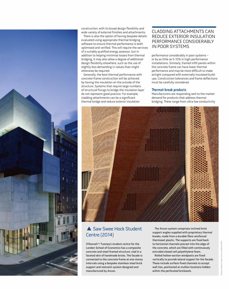
� Saw Swee Hock Student Centre (2014)
O’Donnell + Tuomey’s student centre for the London School of Economics has a composite concrete and steel-framed structure, clad in a faceted skin of handmade bricks. The facade is connected to the concrete frame at one-storey intervals using a bespoke stainless-steel brick support and restraint system designed and manufactured by Ancon.
The Ancon system comprises inclined brick support angles supplied with proprietary thermal breaks, made from a durable fibre-reinforced thermoset plastic. The supports are fixed back to horizontal channels precast into the edge of the concrete, which are filled with continuously extruded closed-cell polyethylene foam.
Rolled hollow-section windposts are fixed vertically to provide lateral support for the facade. These include surface-fixed channels to accept wall ties, positioned at mullion locations hidden within the perforated brickwork.
CLADDING ATTACHMENTS CAN REDUCE EXTERIOR INSULATION PERFORMANCE CONSIDERABLY IN POOR SYSTEMS

14 | CQ | AUTUMN 2016
FOCUS | THERMAL BRIDGING
wall ties and lintels for masonry construction, to load-bearing insulation products for cantilever concrete-frame construction and connecting canopies, brise soleil, parapets etc.
Balconies are probably the most common example of cantilever construction where excessive heat loss can result from inadequate detailing of the junction. A simple and well-tested solution is to use proprietary connectors such as those made by Ancon, HALFEN and Schöck, which transfer moment, shear, tension and compression forces, while also providing a thermal break. In the case of the Schöck system, this is achieved through a combination of stainless steel connecting rods, which conduct around 60% less heat than steel rebar, and rigid EPS insulation that conducts over 95% less heat than the structural concrete it abuts.
In addition to offering technical advice on thermal bridging and psi values, some manufacturers also provide design tools and apps to ensure the correct product is specified and the required thermal-performance values are calculated for use in SAP and SBEM.
Another useful product for bespoke load-bearing junctions and resolving tricky thermal bridges is structural insulating foam, such as Cavalok Compacfoam, which is made from a type of expanded polystyrene. This very lightweight material has the strength to support large compressive loads, while also conducting very little heat. It can also be easily cut and used with screws without pre-drilling, making it easy to work with on site.
Visual concreteRealising visual concrete both internally and externally brings the challenge of where to locate the insulation in what is ostensibly a monolithic structure. The simplest solution is to use concrete sandwich construction, where rigid insulation is placed between internal and external concrete leaves, which are structurally linked by cast-in ties passing through the insulation.
A proven means of producing sandwich construction is the Thermomass system, which was developed over 30 years ago. It features rigid insulation and high-strength fibre-composite connectors made from reinforced polymer for long-term structural integrity and very low thermal conductivity. This effectively eliminates repeated thermal bridging, allowing the concrete sections to be thermally isolated from each another. It is applicable to precast or in-situ concrete construction and has the flexibility to be used with a broad range of concrete types and finishes.
Key referencesFor basic, practical guidance on this topic, a series of illustrated guides on detailing have been produced by Studio Partington (formerly Richards Partington Architects), covering concrete-frame, ICF and masonry construction. These offer good-practice advice on thermal bridging, thermal bypass, airtightness and sequencing. They can be downloaded from www.concretecentre.com (search for “Richards Partington” in the publications section).
High-performance masonry and ICF details can be downloaded from the following organisations:n Concrete Block Association www.cba-blocks.org.uk (aggregate block construction)n Constructive Details www.constructivedetails.co.uk (aircrete block construction)n Local Authority Building Control www.labc.co.uk (aggregate and aircrete block construction)n Insulating Concrete Formwork Association www.icfa.org.uk
Phot
o: w
ww
.bau
-wer
k-st
adt.d
e
� Haus U, 2009This minimalist four-bedroom house in Bühl, south Germany, designed by Thomas Bechtold, has been built using lime sand brick masonry, clad with a 160mm layer of insulation.
However, in thermal bridging terms, there was a problem. Externally the house and garage appear to be a single unit, but internally the “cold” garage ceiling requires thermal isolation from the “warm” residential area. The solution was a specially designed version of the Schöck Isokorb thermal break module type Q – a loadbearing connector for reinforced-concrete slabs with thicknesses between 160mm and 250mm.
The Isokorb type Q was particularly suitable for this project as it also transmits positive shear forces for full-length support. Therefore, by installing the units in the ceiling above the garage, they act as connectors to the outer wall of the house in the form of reinforced-concrete binding beams.
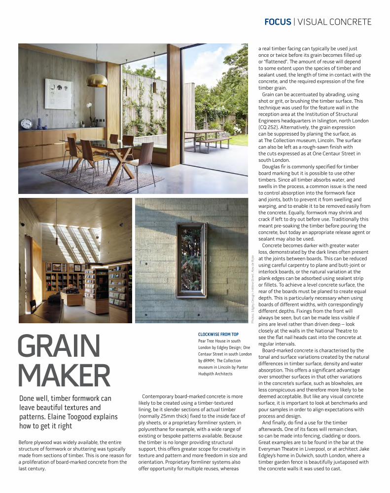
CLOCKWISE FROM TOP Pear Tree House in south London by Edgley Design; One Centaur Street in south London by dRMM; The Collection museum in Lincoln by Panter Hudspith Architects
FOCUS | VISUAL CONCRETE
GRAIN MAKERDone well, timber formwork can leave beautiful textures and patterns. Elaine Toogood explains how to get it right
Before plywood was widely available, the entire structure of formwork or shuttering was typically made from sections of timber. This is one reason for a proliferation of board-marked concrete from the last century.
Phot
os: E
dgle
y D
esig
n; H
élèn
e Bi
net;
Ale
x de
Rijk
e
a real timber facing can typically be used just once or twice before its grain becomes filled up or “flattened”. The amount of reuse will depend to some extent upon the species of timber and sealant used, the length of time in contact with the concrete, and the required expression of the fine timber grain.
Grain can be accentuated by abrading, using shot or grit, or brushing the timber surface. This technique was used for the feature wall in the reception area at the Institution of Structural Engineers headquarters in Islington, north London (CQ 252). Alternatively, the grain expression can be suppressed by planing the surface, as at The Collection museum, Lincoln. The surface can also be left as a rough-sawn finish with the cuts expressed as at One Centaur Street in south London.
Douglas fir is commonly specified for timber board marking but it is possible to use other timbers. Since all timber absorbs water, and swells in the process, a common issue is the need to control absorption into the formwork face and joints, both to prevent it from swelling and warping, and to enable it to be removed easily from the concrete. Equally, formwork may shrink and crack if left to dry out before use. Traditionally this meant pre-soaking the timber before pouring the concrete, but today an appropriate release agent or sealant may also be used.
Concrete becomes darker with greater water loss, demonstrated by the dark lines often present at the joints between boards. This can be reduced using careful carpentry to plane and butt-joint or interlock boards, or the natural variation at the plank edges can be adsorbed using sealant strip or fillets. To achieve a level concrete surface, the rear of the boards must be planed to create equal depth. This is particularly necessary when using boards of different widths, with correspondingly different depths. Fixings from the front will always be seen, but can be made less visible if pins are level rather than driven deep – look closely at the walls in the National Theatre to see the flat nail heads cast into the concrete at regular intervals.
Board-marked concrete is characterised by the tonal and surface variations created by the natural differences in timber surface, density and water absorption. This offers a significant advantage over smoother surfaces in that other variations in the concrete’s surface, such as blowholes, are less conspicuous and therefore more likely to be deemed acceptable. But like any visual concrete surface, it is important to look at benchmarks and pour samples in order to align expectations with process and design.
And finally, do find a use for the timber afterwards. One of its faces will remain clean, so can be made into fencing, cladding or doors. Great examples are to be found in the bar at the Everyman Theatre in Liverpool, or at architect Jake Edgley’s home in Dulwich, south London, where a timber garden fence is beautifully juxtaposed with the concrete walls it was used to cast.
Contemporary board-marked concrete is more likely to be created using a timber-textured lining, be it slender sections of actual timber (normally 25mm thick) fixed to the inside face of ply sheets, or a proprietary formliner system, in polyurethane for example, with a wide range of existing or bespoke patterns available. Because the timber is no longer providing structural support, this offers greater scope for creativity in texture and pattern and more freedom in size and orientation. Proprietary formliner systems also offer opportunity for multiple reuses, whereas
16 | CQ | AUTUMN 2016
STRUCTURES | FIRE RESISTANCE
Imag
e: P
aul M
ello
n Co
llect
ion
in th
e Ya
le C
ente
r for
Brit
ish
Art
RESISTANCE TO FIRE A concrete or masonry structure can significantly reduce fire damage to a building, as well as the cost of repair, says Jenny Burridge
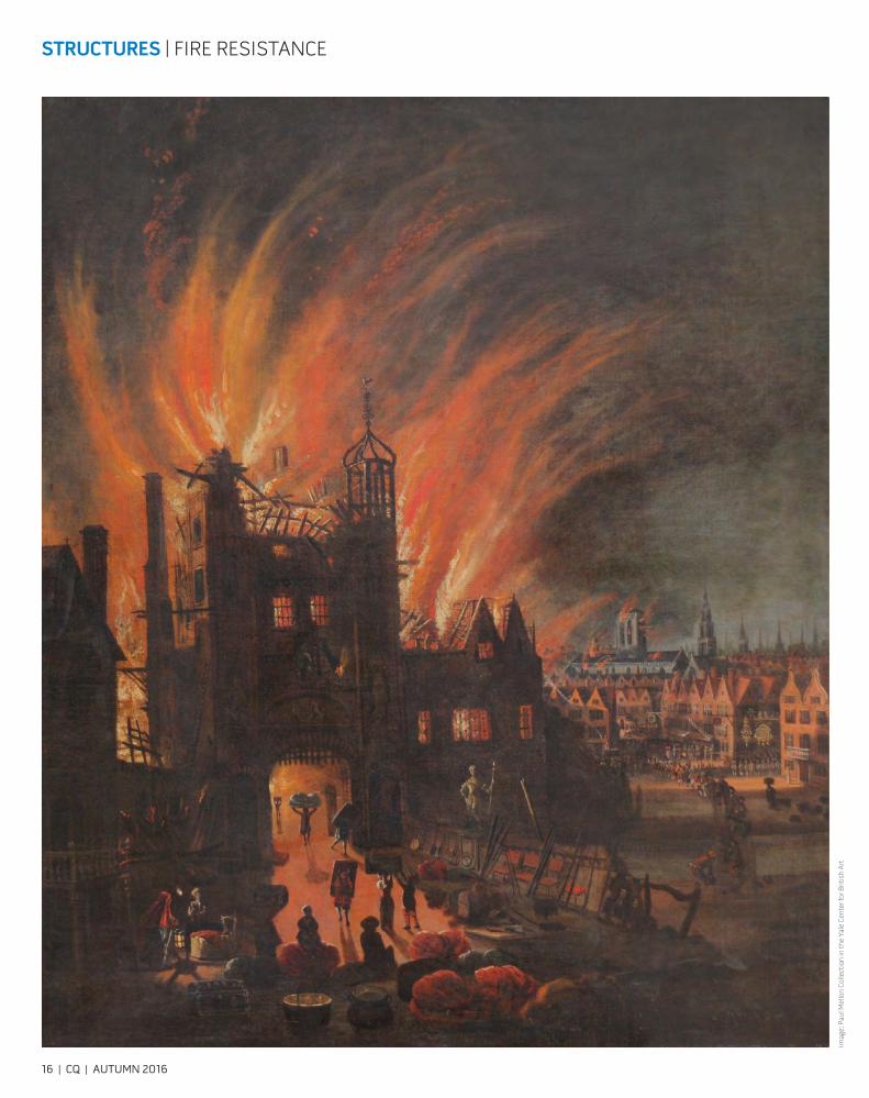
Autumn 2016 marks the 350th anniversary of the Great Fire of London, which started in a bakery on Pudding Lane on 2 September 1666. The conflagration was finally put out on 5 September, after 70,000 of the 80,000 inhabitants of the City of London had been made homeless. There were just six reported casualties, though many historians believe there would have been a great deal more as the poor were not counted – and as the fire was hot enough to melt pottery, there would have been no remains of the victims.
The spread of the fire was exacerbated by the strong east wind. This blew the flames over the firebreaks, then the main way of controlling the spread of fire. Another factor was the closeness of the buildings, with the upper storeys cantilevered over the road, leaving little space between one side of the street and the other.
Most of the buildings were made of timber, although it was acknowledged at the time that
timber houses were more prone to fire than masonry. The Great Fire of 1666 may be the best known, but there had been many other significant fires in London, notably in 1135 and 1212, after which thatched roofs had been banned. But masonry houses were, at that time, more expensive to build, so the houses of the poor were typically made from timber.
The London Building Act of 1667 banned timber-framed houses in the City of London and stated that masonry should be used as the structural material. This was extended to Westminster in 1707, and to the rest of London by 1774. There has been no great fire in London since 1666, due in significant part to the restrictions laid down in the 1667 Act and subsequent ones.
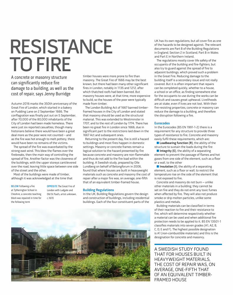
Returning to the present day, fire is still a hazard to buildings and most fires happen in domestic settings. Masonry or concrete frames remain a logical solution to the hazard presented by fire because concrete and masonry are non-flammable and thus do not add to the fire load within the building. A Swedish study, prepared by Olle Lundberg on behalf of Betongforum in 2006, found that where houses are built in heavyweight materials such as concrete and masonry the cost of repair after a major fire was, on average, one-fifth that of an equivalent timber-framed house.
Building RegulationsIn the UK, Building Regulations govern the design and construction of buildings, including residential buildings. Each of the four constituent parts of the
BELOW Following a fire at Tytherington School in Cheshire, a concrete teaching block was repaired in time for the following term
UK has its own regulations, but all cover fire as one of the hazards to be designed against. The relevant documents are Part B of the Building Regulations in England, Section 2 in Scotland, Part B in Wales and Part E in Northern Ireland.
The regulations mostly cover life safety of the occupants of the building and fire-fighters, but also try to guard against the spread of fire to adjacent buildings, which proved such a problem in the Great Fire. Reducing damage to the building itself is a secondary issue and not really covered. But it is often important that repairs can be completed quickly, whether to a house, a school or an office, as finding somewhere else for the occupants to use during the works can be difficult and causes great upheaval. Livelihoods are at stake, even if lives are not lost. With their fire-resisting properties, concrete or masonry can reduce the damage to a building, and therefore the disruption following a fire.
EurocodesIn the Eurocodes (BS EN 1991-1-2) there is a requirement for any structure to provide three types of resistance to fire. Concrete and masonry easily fulfil these requirements, which are: n Loadbearing function (R), the ability of the
structure to sustain the loads during the firen Integrity (E), the ability of a separating
element to prevent the passage of flames and hot gases from one side of the element, such as a floor or a wall, to the othern Insulation (I), the ability of a separating
element, such as a floor or wall, to restrict the temperature rise on the side of the element that is not exposed to fire.
Concrete and masonry do not burn – unlike other materials in a building, they cannot be set on fire and they do not emit any toxic fumes when affected by fire. They will also not produce smoke or drip molten particles, unlike some plastics and metals.
Building materials can be classified in terms of their reaction to fire and their resistance to fire, which will determine respectively whether a material can be used and when additional fire protection needs to be applied to it. BS EN 13501-1 classifies materials into seven grades (A1, A2, B, C, D, E and F). The highest possible designation is A1 (non-combustible materials) and this is the designation for concrete and masonry.
OPPOSITE The Great Fire of London with Ludgate and Old St Paul’s, artist unknown, c.1670
A SWEDISH STUDY FOUND THAT FOR HOUSES BUILT IN HEAVYWEIGHT MATERIALS, THE COST OF REPAIR WAS, ON AVERAGE, ONE-FIFTH THAT OF AN EQUIVALENT TIMBER-FRAMED HOUSE

18 | CQ | AUTUMN 2016
STRUCTURES | FIRE RESISTANCE
The rate of increase of temperature through the cross-section of a concrete element is relatively slow. This means that the internal zones of the concrete do not reach the same high temperatures as a concrete surface exposed to flames. A standard BS ISO 834/BS 476 fire test on a concrete wall showed that the surface reached a temperature of 900°C, but that this reduced to 450°C at 25mm, where the reinforcement might be located, and further reduced to 230°C at 50mm into the concrete. In a 200mm-thick wall this means that 75% of the concrete is effectively unaffected by the one-hour fire. The tabulated data in Eurocode 2 parts 1-2 (BS EN 1992-1-2) indicates that a 130mm-thick loadbearing concrete wall will give one-hour fire resistance for the three requirements above (REI).
Masonry has many of the same properties as concrete, but tends not to be reinforced. This means that it has excellent fire-resisting capacity. In Eurocode 6 parts 1-2, the type of block or brick and the density all affect the fire resistance, but generally a standard 100mm-thick masonry wall will be more than sufficient to resist a one-hour fire.
Spalling in concreteSpalling is a phenomenon that may occur in particular circumstances in which the surface concrete breaks away at elevated temperatures.
CLOCKWISE FROM LEFT Fire damage to concrete on a circular column, exposing the reinforcing cage; Concrete spalled from a slab soffit, revealing pink discolouration; Reinforcement exposed on a beam soffit following a fire. Repair to concrete structures is usually possible following a fire.
In normal buildings under normal fire loads it may not occur at all, or is not of significance. For normal buildings (including offices, schools, hospitals and housing) subjected to normal fires, design codes already take into account the effect of spalling. Because spalling is caused by steam forming in the concrete and creating pressure that builds up until it is released, less porous high-strength concrete (above 60MPa cube strength) and concrete with a high moisture content are more susceptible.
Where spalling is considered to be a major risk, there are methods to reduce or eliminate the likelihood of damage. One of these is to provide external protection to the concrete, but a more efficient solution is to incorporate polypropylene fibres within the concrete mix. The fibres melt at 160°C and thus provide cracks through which the steam can escape. The Concrete Centre guide (Performance of Concrete Structures in Fire, CCIP031, 2011) for structural engineers and specialist fire consultants presents the principles of fire behaviour of concrete structures and how to reduce the probability of spalling. Guidance is also provided for specialist areas such as tunnels.
Repairs to concreteThe vast majority of concrete and masonry structures are not destroyed in a fire, and one of the advantages of concrete structures is that they can usually be easily repaired. The modest floor loads that are actually applied in most structures,
Phot
os: S
andb
erg
TABLE 1: STAGES IN THE ASSESSMENT AND REPAIR PROCESS
Stage Activities
1 Preliminary inspection• Carry out preliminary inspection of the structure• Prop any members that are in a critical condition
2 Assessment of damage• On-site assessment of the structure to determine the extent of the damage by visual inspection, breakouts and hammer testing• Decide whether any elements need further assessment and where only cosmetic repair is required (such as cleaning and painting)
3 Testing and detailed inspection• Break out spalled concrete to determine the depth of fire damage• Carry out lab testing to determine the depth of fire damage• Assess the residual strength of the fire-damaged concrete• Carry out a dimensional survey to check on deflections and movements of the structure
4 Design of repairs to structural elements• Determine the structural capacity of the fire-damaged members• Decide on the extent of any demolition• Decide on the extent of repairs
5 Implement structural repairs• Select suitably qualified contractor• Agree method statements and sequencing of the repair work• Carry out repair work
Source: Technical Report 68, the Concrete Society
combined with the relatively low temperatures experienced in most building fires, mean that the loadbearing capacity of concrete is largely retained both during and after a fire. For these reasons, often all that is required is a simple clean-up.
After a fire, a concrete structure should be assessed. It is normally sufficient to take ”soundings” on the damaged concrete to determine the degree of deterioration. A hammer and chisel can be used to indicate the ring of sound concrete or the dull thud of unsound material. Also, the concrete aggregate changes to a pink/red colour at 300°C, the temperature which indicates the start of strength loss. Thus, a survey taking small cores can determine the extent of concrete that should be removed.
A structural evaluation should follow the material investigation to determine the method of repair. Repair of concrete exposed to high fire temperatures is often preferable to demolition and reinstatement for cost reasons. Technical Report 68 from the Concrete Society, ”Assessment and repair of fire-damaged concrete”, provides more detail on this topic (see table, left).
It is important that we design buildings and structures that minimise risk to both people and property as effectively and as efficiently as possible. Because of concrete’s inherent material properties, it can be used to minimise fire risk for the lowest initial cost while requiring the least in terms of ongoing maintenance.
RETRO CONCRETE
LASTING IMPRESSIONCHRIS LOYN
“A PERFECT FOIL TO FEMINITY”The decision to let the brutalist architects of the Barbican Centre – Chamberlin, Powell and Bon – design an entire new college certainly shook things up at the University of Cambridge in the early 1960s. It seems to have got CQ editor George Perkins slightly flustered too.
New Hall – completed 50 years ago – was the university’s first purpose-built women’s college, and part of a new wave to be built in a bold modernist style. On visiting, Perkins found it a “stimulating experience” to walk amid the white-concrete courts and fountains, noting the “quiet domesticity” of the residential block, and the dome of the dining hall “like the separated segments of an orange”.
But could such robust materiality and strong forms really be suitable for the fairer sex? “Apart from the symbolic inference which may be drawn from domes and curves, there is nothing obvious in these chalky masses of concrete and brick to suggest femininity: rather an image of rugger and tobacco comes to mind,” Perkins ruminates, before (almost) getting with the times: “Perhaps with the narrowing gulf between the sexes, this is appropriate. Perhaps also this coolly austere setting is a perfect foil to femininity, wanting only the warmth and animation of its inmates.”Access the full CQ archive at www.concretecentre.com/cq
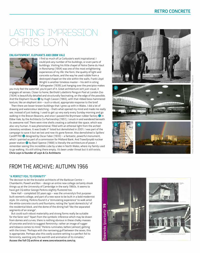
ENLIGHTENMENT, ELEPHANTS AND EBBW VALEI find so much of Le Corbusier’s work inspirational, I could pick any number of his buildings, or even parts of buildings. Visiting his little chapel of Notre Dame du Haut in Ronchamp (1954) was one of the most enlightening experiences of my life: the form, the quality of light and concrete surfaces, and the way he used rubble from a destroyed chapel on the site within the walls. Frank Lloyd Wright is another timeless master – his skill in siting Fallingwater (1939) just hanging over the precipice makes
you truly feel the waterfall, you’re part of it. Great architecture isn’t just visual, it engages all senses. Closer to home, Berthold Lubetkin’s Penguin Pool at London Zoo (1934) is beautifully detailed and structurally fascinating, on the edge of the possible. And the Elephant House 1 by Hugh Casson (1965), with that ribbed boss-hammered texture, like an elephant skin – such a robust, appropriate response to the brief.
Then there are lesser-known buildings that I grew up with in Wales. I did a lot of drawing and watercolour sketching – that’s what opened my mind and made me really see, instead of just looking. I used to get up very early every Sunday morning and go walking in the Brecon Beacons, and once I passed the Brynmawr rubber factory 2 in Ebbw Vale, by the Architects Co-Partnership (1951). I snuck in and wandered beneath its awesome roof. There were nine shells creating a cathedral-like space, which was also very human. It was phenomenal, filled with an ethereal light from the arched clerestory windows. It was Grade II* listed but demolished in 2001. I was part of the campaign to save it but we lost and now it’s gone forever. Also demolished is Spillers’ Cardiff Mill 3 designed by Oscar Faber (1933) – a fantastic, powerful monument, which I painted as part of a commission for Midland Bank. And Trawsfynydd nuclear power station 4 by Basil Spence (1968) is literally the architecture of power. I remember seeing this incredible cube by a lake in North Wales, where my family used to go walking. It’s still sitting there empty. It’s been under threat but it still exists. Chris Loyn is founder of Loyn & Co Architects
FROM THE ARCHIVE: AUTUMN 1966
1
2
3 4
Phot
os: A
rchi
tect
ural
Pre
ss A
rchi
ve /
RIBA
Col
lect
ions
; Vea
le &
Co
/ The
Conc
rete
Soc
iety
; Chr
is L
oyn;
Mag
nox
Ltd
Phot
o: F
ilipp
o Po
li
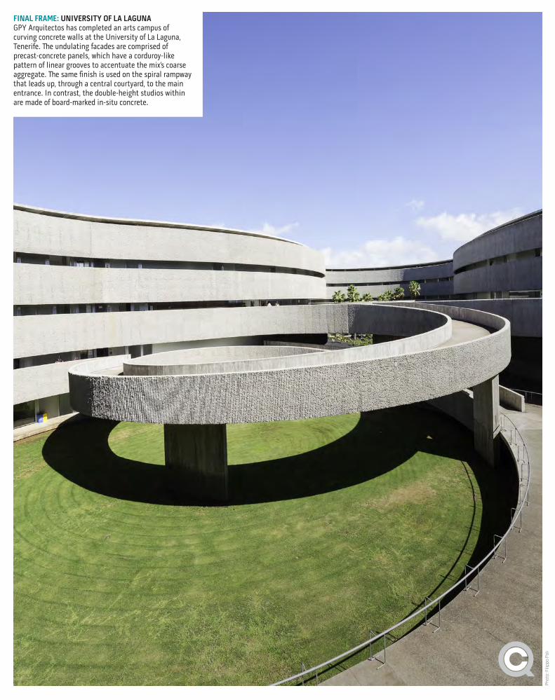
FINAL FRAME: UNIVERSITY OF LA LAGUNAGPY Arquitectos has completed an arts campus of curving concrete walls at the University of La Laguna, Tenerife. The undulating facades are comprised of precast-concrete panels, which have a corduroy-like pattern of linear grooves to accentuate the mix’s coarse aggregate. The same finish is used on the spiral rampway that leads up, through a central courtyard, to the main entrance. In contrast, the double-height studios within are made of board-marked in-situ concrete.