Embed Size (px)
Citation preview

Budapest Univesity of Technology and EconomicsDepartment of Building Machines, Materials Handling Machines and Manufacturing Logistics
and Department of Construction Technology and Managementand Department of Construction Technology and Management
Construction EquipmentConstruction EquipmentConcrete & Asphalt WorksConcrete & Asphalt Works
Edited by: József Károly Ph.D. studentand Dr. Zoltán A.Vattai
Translated by: Dr. Zoltán A.Vattai
Budapest, 2009-2010

Concrete and asphalt works
extraction (excavation)processing – crushing
– sizing
Aggregate production (at pit or quarry):
Batching (mixing) at plant:
– aggregates: by fractions, in open-air deposits or in chambered silos– fines (cement limestone dust): in silos (handled by compressed air)
– washingBatching (mixing) at plant: Receiving and storing rough material:
Scaling and batching components:
fines (cement, limestone dust): in silos (handled by compressed air)– bitumen: in tanks, as heated liquid
weight measuring batching according to mixing formulas
Drying aggregates (asphalt only):
– weight measuring, batching according to mixing formulas– pan-, conveyor belt- or electronic scales
intermittent mixer: in rotary dryer re sizing (re screening) and scaling
mixing: pug-pressure mixing (kneading) (asphalt, continuous: dryer-mixer drum)
– intermittent mixer: in rotary dryer, re-sizing (re-screening) and scaling– continuous mixer: in dryer-mixer drum
Processing mixtures on site: transporting: dumper truck (asphalt), mixer truck (concrete)
spreading, compacting: by asphalt- or concrete finisherspreading, compacting: by asphalt or concrete finisherheat-curing, aging (concrete)curing (concrete)
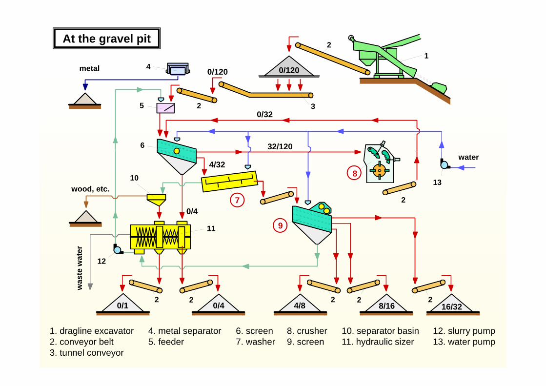
12At the gravel pit
0/120 0/1204
5 32
metal
32/120
5
6
0/3232
4/32
32/120
810 13
water
wood, etc.
8
0/47
911
2
9
7
12
aste
wat
er
0/1 0/4 4/8 8/16 16/322 22 2 2
wa
4. metal separator5. feeder
12. slurry pump13. water pump
1. dragline excavator2. conveyor belt3. tunnel conveyor
10. separator basin11. hydraulic sizer
8. crusher9. screen
6. screen7. washer

Crushers
breaker / mill impact crusher
cone crusherjaw crusher
Dmax = 2500 mm Q = 2300 to/hdmax = 25 mm P = 3500 kW
45
Impact crusher „Mammut”(Krupp)
14
8 6
84
1. case2. rotor4
53. crushing piece4. impact piece5. impact piece
li d
1
2
7
cylinder6. feeder7. tiltable upper case8. wear parts
5 9 3
8. wear parts9. tiltable upper case
cylinder

Cone crusher
1. Feed hopper2. Bowl hopper
24. Main frame cap25. Feed plate
3. Adjustment cap seal
4. Feed cone5. Cover plate6. Torch ring7 Main shaft
26. Main shaft nut27. Adjustment cap28. Main frame pin29. Adjustment ring30. Upper spring
segment7. Main shaftsleeve
8. Bowl9. U-shaped bolt
and washer10. Adjustment ring
d t ll
segment31. Spring32. Spring bolt33. Socket liner34. Main frame liner35. Lower spring
tdust collar11. Bowl liner12. Mantle13. Head14. Socket seal ring15. Gear
segment36. Socket37. Countershaft
box guard38. Oil flinger39. Crusher sheave
16. Arm guard17. Pinion thrust
washer18. Pinion19. Inner eccentric
bushing
40. Sheave tapersleeve
41. Countershaft42. Outer countershaft
bushing43 Oil flinger housingbushing
20. Eccentric21. Outer eccentric
bushing22. Main frame23. Step bearing
43. Oil flinger housing44. Countershaft box45. Inner countershaft
bushing46. Countershaft
box sealplate 47. Main shaft

Cone crusher
Jaw crusher
Impact crusher

Gravel sizing (screening)
hydraulicmechanical
%
flat screen drum screen
Q Q Q
100
80
60szQ
eria
l ( Q
), %
Q = +Qr szQ40
20
0
Qr
unt o
f mat
eMechanical screening
Q szQ
0 d maxdgrid size ( log d ), mmam
ou
Qrz
Hydarulic sizing
settling velocity of grains heavier than water isfunction of their sizes particles lighter than water are floating on theparticles lighter than water are floating on thesurface and let out to waste tanks (washing)bigger grains (d > 4 mm) are separatedto fractions by water on flat screens slurry (water + d < 4 mm grains + pollutants)slurry (water + d < 4 mm grains + pollutants)is further screened by hydraulic screens

Water-content detection and measurement
a.) Electric resistancemeasurement(aggregate)
b.) Neutron radiationmeasurement
c.) Electric resistancemeasurement
(mixture)(aggregate) (mixture)
1. mixer pan1. mixer pan2. mixer shaft3. water inlet

Aggregate (batching-) feedersSector gate feeder
Delivery rollerDelivery roller
Vibratory feeder1. bunker (silo)2. pneumatic (hydraulic) cylinder3. sector gate4. control track5-6. position sensors
Conveyor scalebunker
slide gate
1. bunker (silo)2. conveyor belt3. senzor roller
Belt feeder4. manometer5. driving unit6. display

Cement feeders
Screw feeder
Cellular wheel (drum) feederCellular wheel (drum) feeder
1. steel tube 3. gear (drive)2. screw 4. engine (motor)
Pneumatic feeder (aerator)1A-A section
air permeable layer
2
34
1. cement bunker (silo)2. compressed air3. pneumatic lock and cylinder4. baffle (spreader)
56
to scale
4. baffle (spreader)5. compressed air (P = 0.05 Bar)6. pneumatic lock and cylinder

5
12
AgitatormixerVertical-axle (pan) concrete mixers
211
9 10 1012
2 13 14
11
10
1 45 6
17
7 63815
4 124 123 16Pan mixer
7 geared transmission7. geared transmission8. discharge door9. discharge door drive
10. feeder11 water inlet
8
2
11. water inlet12. driver13. dead-axle (sun) gear14. revolver gear15 planetary mixing
1. mixer pan2. agitator3. mixing blade 4
14. clearing blade5. engine6. V-belt drive
15. planetary mixingblades
16. cylinder17. wear lining

Twin-shaft mixer, blades and material flow
Horizontal axle (shaft) mixers
Single-shaft mixer, blades Twin shaft mixer, blades and material flowSingle shaft mixer, blades
Twin shaft mixer drive Continuous mixer
3 4 53
B. Double enginedA. Single enginedTwin-shaft mixer drive
1
6
2
Continuous mixer
1 1 6
2
3 51. engine2 V-belt drive 4 cardan gear
74
53
33 5
5. bevel gear6. cardan axle
2. V-belt drive3. gear4. synchronizer
gears
4. cardan gear5. mixer shaft6. charging7. discharging
1. engine2. V-belt drive3. worm-gear

Concrete batching plants
2
Horizontal system Vertical (tower) system
A. Mobile( )
1. tunnel conveyor2 conveyor belt
3
2(+ star depo) 2. conveyor belt3. rotatory chute4. chambered
aggregate silo5 t l
4
65. aggregate scale6. cement silo7. cement screw8. cement scale
7
9. control room10. mixer
5
910
8B. Portable(+ feeder line)
12

4
5
Continuous concrete mixing plant 1. feeder line with
151. feeder line with
batching belt scale2. conveyor belt3. charging belt4. cement silo
3
67
8
4. cement silo5. cement conveyor
screw6. cement scale7. cement batcher screw
28
9
108. water batcher scale9. continuous mixer
10. concrete delivery belt 9
Concrete delivery(through collector basin)
Mobile plant
9
Mobile plant

Aggregate storage and batching
Semicircular („star”) deposit
- fractions of aggregate are separated- water content measured and controlled- heating facilities for hot concrete(winter-time concreting)
- grain-size distribution composed andfit to concrete when batching
G-H section E-F section
Row storage plant

Concrete (wet) hoppers and containers
„Shoe”-Container
On smaller hopper containers the sector gate isoperated by simple levers (a) but on bigger onesoperated by simple levers (a) but on bigger onessegment gears and handwheels are provided (b)

Concrete pumps
Rotary
Truck mounted mobile mixer drum, cross section
Piston

Truck mounted concrete pumpand delivery boom
Mobile concrete pump
Mixer truck (charger chute open)
Mixer truck with concrete pump and delivery boom (”pumix”) Concrete pump spare parts

Mi t k ith d li (i ti )Mixer truck with delivery conveyor (in action)
Pump - mixer truck (”pumix”)Mixer truck and ”pumix” co-operating at the site
Mixer truck with delivery conveyor (riding position) Mixer feeding the pump

Concrete pump allocations and configurations
(Concrete) pump directing hand signals

Concrete work-in(booms and vibrators)(booms and vibrators)
A-A sectionelectromotor
Immersible (poker) vibratorsStationary concrete boom
eccentric (a) and planetary system (b)
A-A section
flexible shaft
A-A sectionrubber cover pipe
formwork vibrator head
vibrating cylinder
„sword” head
cable shaftself-aligning ball-bearing

Shotcrete (Gunite) pumps
1. dry mix hopper2. rotary feeder wheel3. feeder pocket4. dry mix conveying
by compressed air
Structural maintenancey p
Free-form architecture
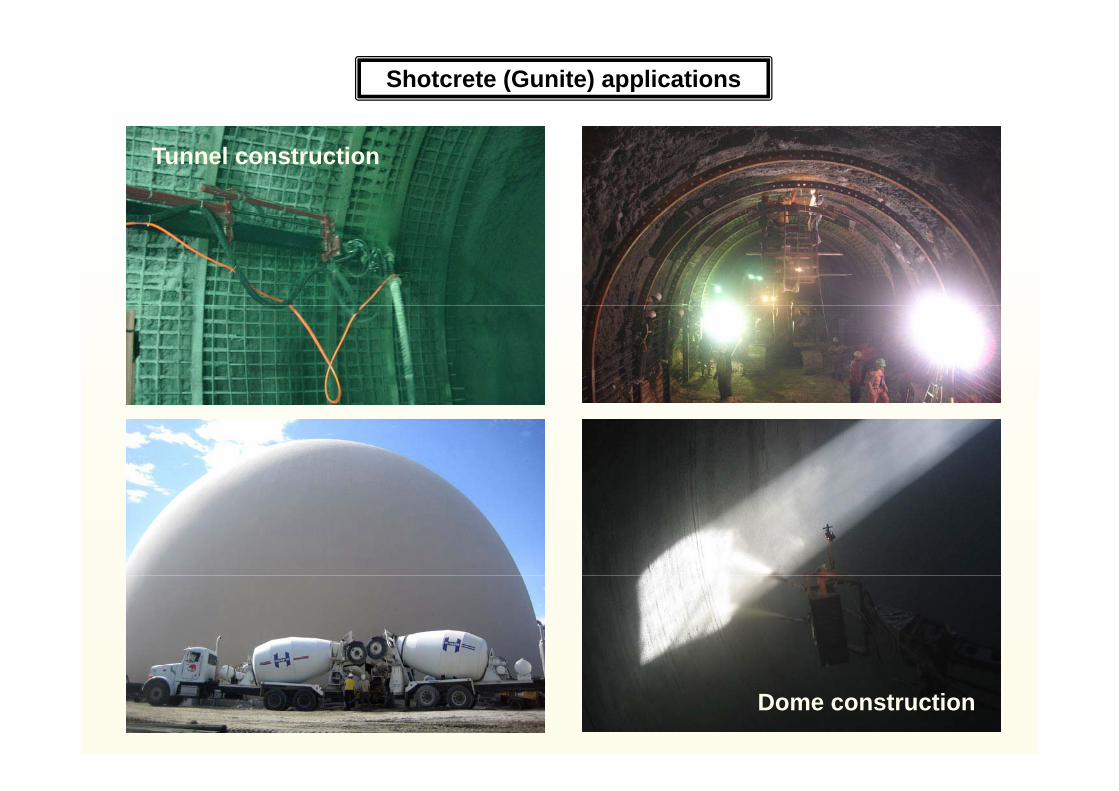
Shotcrete (Gunite) applications
Tunnel construction
Dome construction

Shotcrete (Gunite) applications
R t i i ll t tiRetaining wall construction(permanent or temporary),
paving, landscaping

Ride-on typeddouble rotor power trowel
Power trowels (finishers)p
Power trowels in action
Walk-by typedsingle rotor
power trowel

10Immersible vibratorConcrete paver (finisher)
9
1112
3 41 25 6
1 bogie track
97
8
1. bogie track2. mould3. distributor screw4. Immersible vibrator5. surface vibrator
8. exciter mass9. power cable
10. hydraulic cylinder5. surface vibrator6. floating trowel7. motor
10. hydraulic cylinder11. tip shaft12. plate spring
Course spreading Kerb (curb) construction by concrete finisher

Joint bars: bond breaker coated steel bars inserted across the extension joints
Concrete paver (finisher) with joint-bar inserter
5 44 9
Joint-bars: bond breaker coated steel bars inserted across the extension joints
3. bogie track4. elevation control
Functions: retaining vertical dislocation of adjoining concrete panels
5 4
13
14
4
13
95. main frame6. distributor screw7. immersible vibrators8 screed (mould)
6 71 3 28 10 11 123
8. screed (mould)9. joint-bar inserter
10. joint-bar vibrator11. transversal screed12 l it di l d12. longitudinal screed13. level detectors14. guide wire
1. loose concrete mix2. compacted concrete layer
Transversal joint-bars inserted(for joining parallel lanes)Longitudinal joint-bar inserter

Effect of weather conditions on concrete works
Hardening time of concrete is effected by the temperature of the environment:
Final hardness of concrete is attained in 28 days at about +20 oCAt +5 oC to attain final hardness of concrete takes 35-50 days
If water content of concrete mixture froze at beginning of hardening process, before attaining it’s final hardness, it can not resist pressure of solidifying (extending) water (i ) it k d h th i t d d (d i d) fi l t th (h d )(ice), it cracks and never reaches the intended (designed) final strength (hardness)
At about freezing-point:
Hot concrete” production (delivery temperature: 40 45 oC)
H t
„Hot concrete production (delivery temperature: 40 - 45 oC)
Admixing „anti-freeze” agent (additive)Limited applicabilityat road construction
Hot summer:
Counter-action:
Problem is the intensive evaporation of water (at the surface)
Using low heat-producing cementsR d i i i t t ( li th t )Reducing mixing temperature (pre-cooling the aggregate)Reducing evaporation (covering fresh concrete, vapour-tight coating)Using retarding admixtures or reducing water content (with admixtures)
Precipitation: Can change water content of the fresh concreteCan corrupt the surface of the fresh concrete structure

16 1312
Intermittent asphalt mixing plant
914 814
115
15
6
18
6
432
1 4
10
17
4
Horizontal system7
10
11. ready-mix container12. bitumen tank13. bitumen heater
1. feeder bunkers2. conveyor belt scale3. conveyor belt
1110
19
14. dust collector15. exhaust ventilator16. control room17. elevator bucket
4. rotary dryer5. hot elevator6. separator 7. scales
18. wire rope19. transporter truck
8. limestone dust silo 9. fines elevator
10. mixerChambered ready-mix container
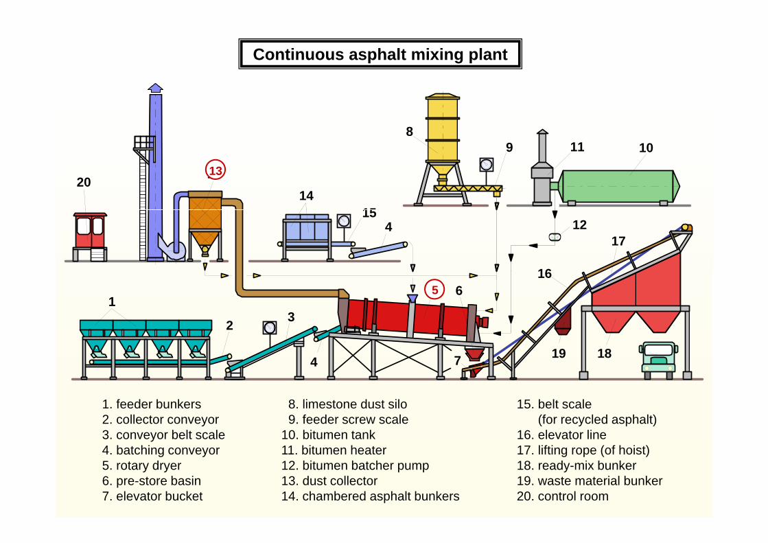
Continuous asphalt mixing plant
98
11 109
13
15
20
11 10
14
13
16
4 1215
17
165
3
6
2
15
4 197 18
15. belt scale (for recycled asphalt)
16. elevator line17. lifting rope (of hoist)
1. feeder bunkers2. collector conveyor3. conveyor belt scale4. batching conveyor
8. limestone dust silo9. feeder screw scale
10. bitumen tank11. bitumen heater g p ( )
18. ready-mix bunker19. waste material bunker20. control room
g y5. rotary dryer6. pre-store basin7. elevator bucket
12. bitumen batcher pump13. dust collector14. chambered asphalt bunkers

A h lt
Pavers (Finishers)
C tAsphalt
30 - 300 mm,more layers, spread in layersCourse thickness
180 - 600 mm,single layer
Concrete
Compactingpreliminary final
by the finisher by rollers
both preliminary and finalby finisher
(higher output vibrators)
Auxiliary units roughening and curing equipments can be attached behind the finisher
mechanical parts in direct contactwith the asphalt can be heated
Direct-feed, low performanceasphalt finisher
2
1
2
65
34 71. dumper truck 2. feeder bunker
3. screed4. level mould5. tamper beam
6. vibro plate 7. push idler
Asphalt finisher in action

1Conveyor-belt asphalt finisher
52
6
1. delivery dumper truck2. feeder bunker
6. main frame7. distributor screw
389 107 4
2. feeder bunker3. conveyor belt4. screed5. level mould
7. distributor screw8. tamper beam9. vibro plate
10. push idler
Finishers applied in groupsFeeding the finisher

Conveyor-belt (scraper-chain) asphalt finisher
seat
control boardexhauster
coolercooler
enginefeederbunker
distributorpanel (screw)
tractor (crawler)conveyor
belt

independent external
Main parts of a conveyor-belt (scraper-chain) asphalt finisher
nickel coated
pscrew drives
nickel coatedscrew segments
alloy-steel chainlinks and bars
independentb lt ( h i ) d i
Feeder (bunker) Conveyor-belts and distributor screws
belt (chain) drives
Bogie types:
•Track (caterpillar)
•Rubber wheel
•Rubber belt (track)
Track (crawler) bogie Rubber wheel bogie
•Rubber belt (track)


Mastic asphalt mixers (boilers)
Fix(batching plant)
V ti l h ft
Horizontal shaftMobile
(masticator)Vertical shaft
Horizontal shaft mastic asphalt mixer Vertical shaft mastic asphalt mixer

Effect of delivery time of mixtures on workability
Workability time of asphalt infunction of mix temperature
and of layer thickness
Asphalt temperature in function of layer thickness and of
cooling time
20
30
me
[min
] tenvironment = 10 oC 160
1406 cmat
ure
[o C] tenvironment = 10 oC
10
20
135 oC
150 oC
Wor
kabi
lity
tim 120
100
80
9 cm
18 cm12 cm
phal
t tem
pera
M i h ldi ti f t i f ti f
1 2 3 4 5 6 7 80
Layer thicknes [cm]
W
1 2 43 560As
p
Cooling time [h]
Maximum holding time of concrete in function of means of transport and of temperature of the environment
Temperature [oC] Transport [h] Casting [h]Transporter
30 - 2019 - 10
9 - 5
30 20
1,01,51,5
0 50
0,50,50,5
0 5
Mixer truck
30 - 2019 - 10
9 - 5
0,500,750,75
0,50,50,5
Dumper truck

Effect of weather conditions on asphalt works
Temperature close to freezing-point:
Asphalt must not be laid on frozen base!
Acceptable air temperature when spreading regarding the type of course
Base course Bond course Wearing courseCourse
S d i t b d f th f b f di h lt it
Temperature > - 3 oC > 0 oC > ( 3 … 6 ) oCaccording to thickness
Hot summer:
Snow and ice must be removed from the surface before spreading any aphalt course on it. Roller compactors must work immediately after (behind) the finisher.
Hot summer:
Rubber-wheel rollers should not be favoured (due to segregation).Delivery temperature must be optimized regarding the temperature of the environment.
Rainy weather:
Handover to traffic is allowed when asphalt temperature got less than 40 oC.
Top (wearing) course must not be spread on wet base or in rainy weather .Rain-water collected on the surface must be removed after rainfall before going on.

Managerial tasks of asphalt surfacing
When ordering asphalt expectations must be set clearly regarding:– quality and composition of mixture (grain-size number, temperature, etc..),– quantity of mixture, location of use, transport route,
When delivering unbroken telecommunication is essential between the place of use and the mixing plant
Before working in quality control is evident (sampling regularly, measuring temperature, visual inspection)
– schedule of delivery broken down to days and to hours.
Visual inspection of asphalt mixtureP C l d BF t
g q y ( p g g y, g p , p )
Proper Cooled BurntFeature
Colour black, weakly sparkling browny, mat
St i i h i tSteaming greyish not steaming tawny
Castability easily castable lumpy scattering
Adhesion adheres properly crust on the surface low or no anyAdhesion adheres properly crust on the surface low or no any
– advancing of the finisher must be adjusted to schedule of delivery and
When working in:advancing of the finisher must be adjusted to schedule of delivery and to performance capacity of roller-compactors.
– wearther and temperature of the environment must be also regarded

Sources of B&W pictures and drawings:
- Bacher Károly, Dr. Lánczos Pál, Dr. Soós László, Építésgépesítés I., Tankönyvkiadó, Budapest, 1985- Dr. Nagy Pál, Építéstechnológia I, Alaptechnológiák, Tankönyvkiadó, Budapest, 1990
É- Soós László, Építőoipari gépek I., Tervezési segédlet, Tankönyvkiadó, Budapest, 1987- Soós László, Építőipari gépek II, Tervezési segédlet, Tankönyvkiadó, Budapest, 1987
![ASPHALT CONCRETE [Types] - KSU Facultyfac.ksu.edu.sa/sites/default/files/AC-1-LabTYPESDISTRESS.pdf · ASPHALT CONCRETE [Types] Introduction ... Sand Asphalt Mix Sand asphalt mixes](https://img.pdfslide.us/doc/110x75/5b72d5437f8b9a674d8d5d0c/asphalt-concrete-types-ksu-asphalt-concrete-types-introduction-sand.jpg)