Embed Size (px)
Citation preview

D-1

CONCEPTUAL WATER REPORT
JN: 9000.100 Page i July, 2016
TABLE OF CONTENTS I. INTRODUCTION ....................................................................................................... 1
II. DESCRIPTION OF DEVELOPMENT .......................................................................... 1
A. Terrain .................................................................................................................... 1
B. Phasing ................................................................................................................... 1
III. EXISTING OFF-SITE WATER SUPPLY FACILITIES ................................................ 2
A. Fish Springs Tank/TMWA System ............................................................................... 2
B. Red Rock Road/TMWA System ................................................................................... 3
C. Stead/TMWA System ................................................................................................ 3
IV. WATER DEMAND ESTIMATES ................................................................................ 3
A. Residential Demand .................................................................................................. 3
B. Non-Residential Demand ........................................................................................... 5
C. Irrigation Demand .................................................................................................... 6
D. Total Demand .......................................................................................................... 7
E. Fire Flow .................................................................................................................. 7
F. Other Demands ........................................................................................................ 8
V. DESIGN CRITERIA .................................................................................................. 8
A. On-Site Water System ............................................................................................... 8
B. Off-Site Water System .............................................................................................. 9
VI. ON-SITE WATER MODEL ......................................................................................10
A. Average Day Demand ............................................................................................. 10
B. Maximum Day Demand ........................................................................................... 10
C. Maximum Day Demand with Fire Flow ...................................................................... 10
D. Peak Hour Demand ................................................................................................. 10
VII. EVALUATION OF ON-SITE WATER SYSTEM ........................................................10
A. Storage.................................................................................................................. 10
B. Distribution ............................................................................................................ 11
VIII. EVALUATION OF OFF-SITE WATER SYSTEM .....................................................12
A. Fish Springs Tank/TMWA System ............................................................................. 12
D-2
CONCEPTUAL WATER REPORT
JN: 9000.100 Page ii July, 2016
B. Red Rock Road/TMWA System ................................................................................. 15
IX. RECOMMENDED WATER SYSTEM ........................................................................15
A. System Description ................................................................................................. 15
B. Opinion of Probable Costs ....................................................................................... 16
C. Permitting Requirements ......................................................................................... 18
D. Construction Considerations .................................................................................... 18
X. CONCLUSIONS ......................................................................................................19
XI. REFERENCES .......................................................................................................20
APPENDICES Appendix A Construction Drawing for 24” TMWA Main in North Virginia Street
Appendix B Irrigation Calculations
Appendix C Water Main Calculations
LIST OF TABLES Table 1: Dwelling Unit Count by Phase ................................................................................. 2
Table 2: Single-Family and Active Adult Residence MDD Calculation ....................................... 4
Table 3: Phase 4 MDD Calculation ....................................................................................... 4
Table 4: Multi-Family Residence MDD Calculation ................................................................. 4
Table 5: Summary of Residential Demands .......................................................................... 5
Table 6: Non-Residential Demands ...................................................................................... 6
Table 7: Irrigation Demands ............................................................................................... 7
Table 8: Summary of Total Demands ................................................................................... 7
Table 9: Preliminary Storage Tank Requirements .................................................................11
Table 10: Preliminary Tank Elevations and Areas Served ......................................................11
Table 11: Pipeline Lengths for Backbone Distribution System ................................................12
Table 12: Off-Site Water Main Sizing ..................................................................................13
Table 13: Off-Site Booster Pump Sizing ...............................................................................14
Table 14: Required Water Main and Booster Pump Sizing with Potable Demand Reduction ......15
D-3

CONCEPTUAL WATER REPORT
JN: 9000.100 Page iii July, 2016
Table 15: Preliminary Opinion of Probable Project Costs: On-Site System ...............................17
Table 16: Preliminary Opinion of Probable Project Costs: Off-Site System ..............................18
LIST OF FIGURES Figure 1: StoneGate Preliminary Phasing Program ................................................................22
Figure 2: Preliminary Tank Locations & Service Areas ...........................................................23
Figure 3: Preliminary Distribution Map ................................................................................24
Figure 4: Preliminary Off-Site Water System ........................................................................25
[File Doc: L:\LAProj\9000.100 - Heinz Ranch Entitlements\Civil\30000 Water Report\Handbook\final\9000.100 Water Report_2016-
0516.docx] July 7, 2016
D-4

CONCEPTUAL WATER REPORT
JN: 9000.100 Page 1 July, 2016
I. INTRODUCTION
StoneGate, a Master Planned Community (MPC) Development, is located 12 miles north of the US395-580/I-80 interchange. The total area of land is comprised of 1,437 acres south of US395 which encroaches on the following parcels: 081-010-18, 081-010-13, 081-110-32, 081-110-33. Heinz Ranch Land Company also holds property on the north side of the freeway consisting of 359 acres that is independent of StoneGate. The site resides within Section 32, T21N, R18E, Section 33, T21N, R18E and Section 5, T20N, R18E, in the City of Reno, Nevada. The proposed StoneGate MPC will consist of 3,815 single-family and 320 multi-family residential units situated on approximately 1,437 acres of the Heinz Ranch in the Cold Springs area of Reno, Nevada. Within the immediate vicinity of StoneGate there is no available water supply. On-site and off-site water supply infrastructure will need to be constructed to bring water to the StoneGate development. The purpose of this report is to evaluate water supply options and provide preliminary design recommendations for the conceptual on-site and off-site water systems.
II. DESCRIPTION OF DEVELOPMENT
A. Terrain
The terrain of the project site varies from a slight incline on the valley floor near US395 to steep mountainous terrain of the northern foothills of Peavine Mountain. The terrain for the StoneGate project becomes steeper to the South and allows for strategic placement of storage tanks throughout the site. B. Phasing
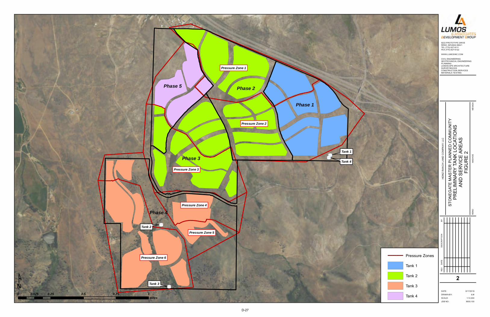
StoneGate is planned to be constructed in five phases as illustrated in Figure 1. Access to all phases is planned to be from the existing US395 interchange. Refer to Table 1 at the end of this section for a summary of dwelling unit (DU) counts for each phase. The first two phases are planned to be constructed in the plain near US395. Phase 1 is planned for the eastern most area of the StoneGate project and consists of an estimated 580 single-family residences and 300 active adult residences. An initial storage tank is planned to be constructed with the Phase 1 water system. Elevations in this phase vary from 5,052 to 5,183 feet and the average lot size phase is 6,276 square feet (sf). Phase 1 is planned to be incorporated into two pressure zones designated as Pressure Zones 1 and 2. Refer to Figure 2 for a map delineating pressure zones. Phase 2 is planned for the area west of Phase 1 and contains an estimated 810 single-family homes, 300 active adult homes, and an elementary school. Elevations in this phase vary from 5,045 to 5,155 feet and the average lot size is 5,775 sf. Phase 2 is planned to be incorporated in Pressure Zones 1 and 2.
D-5

CONCEPTUAL WATER REPORT
JN: 9000.100 Page 2 July, 2016
Phase 3 is planned to be located southwest of Phase 2 and is bordered along the south by an existing active railroad track. Phase 2 is planned to contain an estimated 690 single-family residences and a community center (with recreation area and retail/office space). Elevations in this phase vary from 5,108 to 5,238 feet and the average lot size is 6,749 sf. Phase 3 is planned to be incorporated in Pressure Zones 2 and 3. Phase 4 is located in the southern most section of the StoneGate Project with the highest elevations of all the phases. Phase 4 is planned to contain 600 single-family homes, approximately 25 of which would be large lots equal to or greater than one acre. Elevations in this phase vary from 5,322 to 5,572 feet. Excluding the oversized lots, the average lot size of this phase is 11,596 sf. The oversized lots are planned to have an average lot size of 82,560 sf, contain larger houses, and will have a higher fire flow requirement than the other residential units. Phase 4 is planned to be incorporated in Pressure Zones 4, 5, and 6. Phase 5 is located to the west of Phase 3 and is planned to include 535 single-family residences and 320 multi-family residences. Elevations in this phase vary from 5,066 to 5,183 feet. Phase 5 is planned to be incorporated in Pressure Zones 1, 2, and 3.
Table 1: Dwelling Unit Count by Phase
Phase
Single-Family (DU)
Active Adult (DU)
Multi-Family (DU)
Total (DU)
1 580 300 - 880
2 810 300 - 1,110
3 690 - - 690
4 600 - - 600
5 535 - 320 855
Total 3,215 600 320 4,135
III. EXISTING OFF-SITE WATER SUPPLY FACILITIES
Existing facilities associated with potential off-site water supply sources are described below. A. Fish Springs Tank/TMWA System
An existing storage tank operated by Vidler Water Company and supplied by Fish Springs Valley is located off Matterhorn Blvd. From the storage tank, an existing 30-inch water main runs south along Matterhorn Blvd to the intersection of Lemmon Dr. The Truckee Meadows Water Authority (TMWA) is currently constructing a new high-pressure 24-inch water main as part of the North Valleys Integration Project. The new 24-inch main connects to the existing 30-inch
D-6
CONCEPTUAL WATER REPORT
JN: 9000.100 Page 3 July, 2016
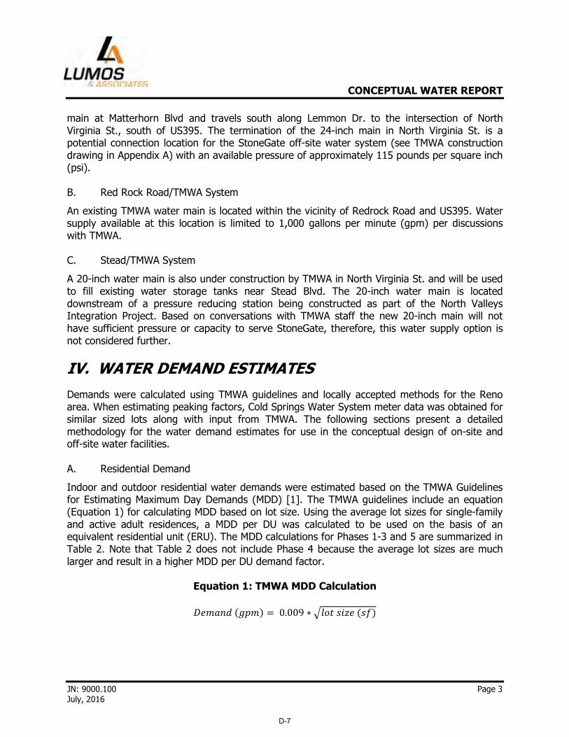
main at Matterhorn Blvd and travels south along Lemmon Dr. to the intersection of North Virginia St., south of US395. The termination of the 24-inch main in North Virginia St. is a potential connection location for the StoneGate off-site water system (see TMWA construction drawing in Appendix A) with an available pressure of approximately 115 pounds per square inch (psi). B. Red Rock Road/TMWA System
An existing TMWA water main is located within the vicinity of Redrock Road and US395. Water supply available at this location is limited to 1,000 gallons per minute (gpm) per discussions with TMWA. C. Stead/TMWA System
A 20-inch water main is also under construction by TMWA in North Virginia St. and will be used to fill existing water storage tanks near Stead Blvd. The 20-inch water main is located downstream of a pressure reducing station being constructed as part of the North Valleys Integration Project. Based on conversations with TMWA staff the new 20-inch main will not have sufficient pressure or capacity to serve StoneGate, therefore, this water supply option is not considered further.
IV. WATER DEMAND ESTIMATES
Demands were calculated using TMWA guidelines and locally accepted methods for the Reno area. When estimating peaking factors, Cold Springs Water System meter data was obtained for similar sized lots along with input from TMWA. The following sections present a detailed methodology for the water demand estimates for use in the conceptual design of on-site and off-site water facilities. A. Residential Demand
Indoor and outdoor residential water demands were estimated based on the TMWA Guidelines for Estimating Maximum Day Demands (MDD) [1]. The TMWA guidelines include an equation (Equation 1) for calculating MDD based on lot size. Using the average lot sizes for single-family and active adult residences, a MDD per DU was calculated to be used on the basis of an equivalent residential unit (ERU). The MDD calculations for Phases 1-3 and 5 are summarized in Table 2. Note that Table 2 does not include Phase 4 because the average lot sizes are much larger and result in a higher MDD per DU demand factor.
Equation 1: TMWA MDD Calculation
��������� � 0.009 ∗ ������������
D-7

CONCEPTUAL WATER REPORT
JN: 9000.100 Page 4 July, 2016
Table 2: Single-Family and Active Adult Residence MDD Calculation
Phase DUs
Average Size per MDD per DU Total MDD
Lot (sf) (gpm) (gpd) (gpm) (gpd)
1 880 6,276 0.7 1,008 616 887,040
2 1,110 5,775 0.7 1,008 777 1,118,880
3 690 6,749 0.7 1,008 483 695,520
5 S.F. 535 5,797 0.7 1,008 375 539,280
Total 3,215 - - - 2,251 3,240,720
An ERU in terms of MDD for StoneGate is represented by 1,008 gallons per day per DU (gpd/DU). With the larger lot sizes in Phase 4, a larger water demand is expected. Lot sizes in Phase 4 can be separated into two categories: those in the wooded area and those in an open area. Based on average lot sizes, each residence in the open area represents 1.4 ERUs and each residence in the wooded area represents 3.7 ERUs. The MDD calculation and ERU conversion factors for Phase 4 are shown in Table 3.
Table 3: Phase 4 MDD Calculation
Phase DUs
Average Size per MDD per DU Total MDD
ERU Conversion
Factor Lot (sf) (gpm) (gpd) (gpm) (gpd)
4 Suburbs 575 11,596 1.0 1,440 575 828,000 1.4
4 Wooded Area 25 82,560 2.6 3,774 65 93,600 3.7
Total 600 - - - 640 921,600 -
For multi-family residences such as the units planned for Phase 5, the TMWA guidelines provide a MDD factor of 0.15 gpm per unit (assumed to exclude irrigation demands) [1]. Each multi-family unit in Phase 5 represents 0.21 ERUs. The MDD calculation and ERU conversion factor for the multi-family residences in Phase 5 are provided in Table 4.
Table 4: Multi-Family Residence MDD Calculation
Phase DUs
MDD per DU Total MDD ERU
Conversion Factor (gpm) (gpd) (gpm) (gpd)
5 M.F.1 320 0.15 216 48 69,120 0.21
1 Excludes irrigation demands.
D-8

CONCEPTUAL WATER REPORT
JN: 9000.100 Page 5 July, 2016
Peaking factors were used calculate average day demand (ADD) and peak hour demand (PHD) from the MDD values presented in Tables 2-4. Based on input from TMWA staff, a MDD to ADD peaking factor of 2.61 was used to calculate ADD. Based on meter data for the Cold Springs water system, a PHD to MDD peaking factor of 1.75 was used to calculate PHD. Both of the peaking factors used for planning purposes are within industry standards. A summary of anticipated residential water demands and ERUs by phase is presented in Table 5.
Table 5: Summary of Residential Demands
Phase DUs
Average Size per Lot (sf)
MDD per DU ADD MDD PHD
ERUs/ MDD Basis (gpm) (gpm) (gpd) (gpm) (gpd) (gpm)
1 880 6,276 0.7 236 339,862 616 887,040 1,078 880
2 1,110 5,775 0.7 298 428,690 777 1,118,880 1,360 1,110
3 690 6,749 0.7 185 266,483 483 695,520 845 690
4 Suburbs
575 11,596 1.0 220 317,241 575 828,000 1,006 805
4 Wooded
Area 25 82,560 2.6 25 35,862 65 93,600 114 93
5 S.F. 535 5,797 0.7 143 206,621 375 539,280 655 535
5 M.F.1 320 - 0.15 18 26,483 48 69,120 84 68
Total 4,135
1,125 1,621,242 2,939 4,231,440 5,142 4,181
1 Excludes irrigation demands.
B. Non-Residential Demand
In addition to the anticipated residential water demands, non-residential demands in the form of a community center and an elementary school are included in the StoneGate project. The elementary school’s demands were calculated on a per student basis. A typical ADD unit factor for a school with a cafeteria and without a gymnasium/shower is 15 gpd per student [2]. With a projected 1,070 students, the anticipated ADD and for the elementary school is 16,050 gpd. Preliminary plans for the community center include a recreation area and approximately 60,000 sf of retail/office space. For the retail/office space, a unit water demand factor of 2.18 gal/sf/month is recommended based on a paper presented at an American Water Works Association conference on estimating commercial/institutional/industrial water demands [3]. The estimated ADD for the retail/office space at the community center is 4,300 gpd. In addition,
D-9

CONCEPTUAL WATER REPORT
JN: 9000.100 Page 6 July, 2016
the estimated ADD for the recreation area at the community center is estimated at 3,300 gpd based on Cold Springs water system meter data for a similar land use. A summary of non-residential water demands and ERUs is tabulated in Table 6. The values presented in Table 6 exclude irrigation demands.
Table 6: Non-Residential Demands
Location
ADD MDD1 PHD1 ERUs/
MDD Basis (gpm) (gpd) (gpm) (gpd) gpm
Elementary School2 11 16,050 29 41,891 51 41.6
Community Center2
Retail/Office Space 3 4,300 8 11,223 14 11.1
Recreational Area 2 3,300 6 8,613 11 8.5
Total 16 23,650 43 61,727 76 61.1
1 Calculated using a MDD/ADD peaking factor of 2.61 and a PHD/MDD peaking factor of 1.75. 2 Excludes irrigation demands.
C. Irrigation Demand
Common areas and open space within the StoneGate development include the entrance to the community, street right-of-ways, channels, the community park, and the community center. The estimated irrigation demand takes into account the trees, plants, turf, and pasture grasses used for landscaping in the various StoneGate open space, common areas, and also the landscaping at the multi-family complex in Phase 5. Single-family and active adult residential landscaping for StoneGate is taken into account with the residential demand calculation as part of the TMWA guidelines (as reflected in Table 5). Drip systems are planned to be installed to irrigate individual plants such as shrubs and trees. Sprinkler systems are planned to be used to irrigate large areas such as turf and pasture grasses. Estimated irrigation demands by phase are summarized in Table 7 and detailed in Appendix B. Irrigation demands in Appendix B are estimated assuming a 32-week watering season. The ADD in Table 7 is calculated by averaging the 32-week irrigation demand over a year. The MDD to ADD peaking factor of 2.61 provides a reasonable estimation of MDD during the watering season while also considering staggered watering days. However, PHD is not applicable because irrigation times are typically scheduled during non-peak hours. Open space irrigation may potentially utilize treated effluent which would result in a reduction in the required MDD for the StoneGate development.
D-10

CONCEPTUAL WATER REPORT
JN: 9000.100 Page 7 July, 2016
Table 7: Irrigation Demands
ADD1 (gpd) MDD2
Phase Trees & Plants Turf Pasture Total (gpm) (gpd)
1 14,761 4,571 2,623 21,955 40 57,303
2 25,301 29,065 12,228 66,594 121 173,810
3 9,012 4,074 4,559 17,645 32 46,053
4 8,465 - 2,985 11,450 21 29,885
5 4,328 1,528 - 5,856 11 15,284
Total 61,867 39,238 22,395 123,500 225 322,335
1 Irrigation demands during an assumed 32-week watering period averaged over a year.
2 Calculated using a MDD/ADD peaking factor of 2.61.
D. Total Demand
Total residential, non-residential, and irrigation water demands are summarized in Table 8.
Table 8: Summary of Total Demands
Item
ADD MDD PHD
(gpm) (gpd) (gpm) (gpd) (gpm)
Residential 1,125 1,621,242 2,939 4,231,440 5,142
Non-Residential 16 23,650 43 61,727 75
Irrigation 86 123,500 225 322,335 -
Total 1,227 1,768,392 3,207 4,615,502 5,217
E. Fire Flow
Lower Pressure Zones 1, 2, and 3
With the construction of Phase 1 (Pressure Zones 1 and 2) of StoneGate, the initial fire flow required will be based on single-family residences. Fire flow for residential homes under 3,600 square feet will be 1,500 gpm, and will need to be provided for two hours. This equates to a residential fire demand of 180,000 gallons. After the construction of Phase 2 (Pressure Zones 1 and 2), fire flow requirements will be dictated by the elementary school which is expected to have similar construction type and size to other schools in the Cold Springs Valley. Per the most recent version of the International Fire Code (IFC), a type IIIA construction at 140,000 sf (typical size and construction for elementary
D-11

CONCEPTUAL WATER REPORT
JN: 9000.100 Page 8 July, 2016
schools in the area) will require 5,500 gpm for 4 hours. With the elementary school, the total fire flow requirement for the system through Phase 2 is 1,320,000 gallons. Installing sprinklers in the school could reduce demand by 50% if approved by the fire authority. Fire flow requirements for Phase 3 (Pressure Zones 2 and 3) and Phase 5 (Pressure Zones 1, 2, and 3) do not exceed that of the elementary school. Upper Pressure Zones 4, 5, and 6
The residential units in the wooded area of Phase 4 (Pressure Zones 4, 5, and 6) are planned to be greater than 3,600 sf. These larger homes will require a fire flow requirement of 2,750 gpm for 2 hours which equates to a fire demand of 333,000 gallons. Buildout Fire Flow Requirements
The total fire flow requirement at buildout for the water system is 1,320,000 gallons in the lower pressure zones and 330,000 gallons in the upper pressure zones. The fire flow for the lower pressure zones could reduce to 660,000 gallons with sprinkler installation at the elementary school. F. Other Demands
In evaluating TMWA water supply facilities (described in Section III) for conceptual design of the off-site water system to StoneGate, other water demands in the Cold Springs area to be considered include:
� Fish Springs Ranch: Existing water demand of 1,600 gpm from 30-inch water main at Matterhorn Blvd and Lemmon Dr.
V. DESIGN CRITERIA
As the StoneGate water system will be connected to and served as part of an existing public water system it falls under Nevada Administrative Code (NAC) 445A66.752 through 445A.66755. These sections of the NAC describe requirements for the existing water system. Recommended design criteria for the on-site and off-site water systems are outlined below. A. On-Site Water System
Design criteria for the on-site water system is in conformance with the NAC and TMWA design standards [4] as follows:
� Storage capacity: Minimum storage capacity will include operating storage, emergency reserve, and fire demand per NAC 445A.6674(b).
o Recommended operating storage = 8 hours of indoor PHD (off-site water system will be designed to provide MDD).
o Recommended emergency reserve = 24 hours of indoor and outdoor ADD.
D-12

CONCEPTUAL WATER REPORT
JN: 9000.100 Page 9 July, 2016
� Distribution system pressures (more stringent of NAC 445A.6711 and TMWA design standards [4]):
o Minimum pressure of 45 psi during MDD. o Minimum pressure of 20 psi during MDD + fire flow. o Minimum pressure of 40 psi during PHD. o Minimum static pressure of 45 psi. o Maximum static pressure of 100 psi.
� Distribution system main sizing [4]: o Minimum water main size of 8-inch diameter. o Maximum velocity of 8 feet per second (fps) during PHD. o Maximum velocity of 18 fps during MDD + fire flow. o Hazen Williams roughness coefficient (‘C’ Value) of 130 for pipe diameters
greater than or equal to 14-inch diameter and 120 for pipe diameters less than 14-inch diameter.
� Minimum 10 ft horizontal and 18-inch vertical (water main above) separation from sewer, storm, and reclaimed water pipelines, unless approved otherwise with special construction per NAC 445A.6715 and TMWA design standards [4].
� Isolation valves required at intervals not to exceed 500 ft, at intervals to isolate no more than (2) fire hydrants at any time, at all main intersections, and at tees/crosses [4].
� Air/vacuum valves required at high points along water pipelines per NAC 445A.67135 and TMWA design standards [4].
� Fire hydrants spacing in accordance with fire department having jurisdiction [4]. � Individual pressure reducing valve (PRV) required when static pressure exceeds 80 psi.
B. Off-Site Water System
The off-site water facilities will be sized to provide MDD to StoneGate. Design criteria in conformance with NAC, TMWA design standards [4], and based on correspondence with TMWA staff are as follows:
� Hazen Williams roughness coefficient (‘C’ Value) of 130 for pipe diameters greater than
or equal to 14-inch diameter and 120 for pipe diameters less than 14-inch diameter [4]. � Minimum depth of cover [4]:
o 48-inches within NDOT right-of-way. o 36-inches in Washoe County (County) right-of-way with established street grade. o 60-inches in County right-of-way without an established street grade.
� Minimum 10 ft horizontal and 18-inch vertical (water main above) separation from sewer, storm, and reclaimed water pipelines, unless approved otherwise with special construction per NAC 445A.6715 and TMWA design standards [4].
� Minimum 20 psi pressure at high point along water main (input from TMWA staff). � Isolation valves required at intervals not to exceed one mile (butterfly valves permitted
for systems with pressures exceeding 150 psi) [4]. � Air/vacuum valves required at high points along the water main per NAC 445A.67135
and TMWA design standards [4].
D-13
CONCEPTUAL WATER REPORT
JN: 9000.100 Page 10 July, 2016
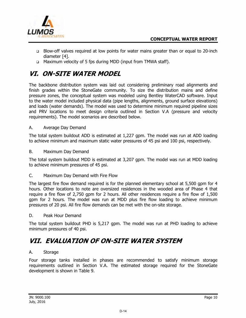
� Blow-off valves required at low points for water mains greater than or equal to 20-inch diameter [4].
� Maximum velocity of 5 fps during MDD (input from TMWA staff).
VI. ON-SITE WATER MODEL
The backbone distribution system was laid out considering preliminary road alignments and finish grades within the StoneGate community. To size the distribution mains and define pressure zones, the conceptual system was modeled using Bentley WaterCAD software. Input to the water model included physical data (pipe lengths, alignments, ground surface elevations) and loads (water demands). The model was used to determine minimum required pipeline sizes and PRV locations to meet design criteria outlined in Section V.A (pressure and velocity requirements). The model scenarios are described below. A. Average Day Demand
The total system buildout ADD is estimated at 1,227 gpm. The model was run at ADD loading to achieve minimum and maximum static water pressures of 45 psi and 100 psi, respectively. B. Maximum Day Demand
The total system buildout MDD is estimated at 3,207 gpm. The model was run at MDD loading to achieve minimum pressures of 45 psi. C. Maximum Day Demand with Fire Flow
The largest fire flow demand required is for the planned elementary school at 5,500 gpm for 4 hours. Other locations to note are oversized residences in the wooded area of Phase 4 that require a fire flow of 2,750 gpm for 2 hours. All other residences require a fire flow of 1,500 gpm for 2 hours. The model was run at MDD plus fire flow loading to achieve minimum pressures of 20 psi. All fire flow demands can be met with the on-site storage. D. Peak Hour Demand
The total system buildout PHD is 5,217 gpm. The model was run at PHD loading to achieve minimum pressures of 40 psi.
VII. EVALUATION OF ON-SITE WATER SYSTEM
A. Storage
Four storage tanks installed in phases are recommended to satisfy minimum storage requirements outlined in Section V.A. The estimated storage required for the StoneGate development is shown in Table 9.
D-14

CONCEPTUAL WATER REPORT
JN: 9000.100 Page 11 July, 2016
Table 9: Preliminary Storage Tank Requirements
Operating Emergency Reserve
Min Tank Size
Required (MG) Tank
Indoor PHD, 8 hrs (gal)
Residential/ Non-
Residential ADD (gal)
Common Area
Irrigation ADD (gal)
Fire Demand (gal)
1 517,440 339,862 21,956 180,000 1.1
2 1,094,407 718,823 84,239 1,140,000 3.0
3 537,600 353,103 11,450 330,000 1.2
4 354,900 233,104 5,857 - 0.6
Total 2,504,347 1,644,892 123,501 1,650,000 5.9
1 Fire storage may be reduced with installation of sprinklers at elementary school.
Preliminary tank elevations and areas served are summarized in Table 10. Storage tank locations and pressure zone delineations are shown in Figure 2.
Table 10: Preliminary Tank Elevations and Areas Served
Tank
Base Elevation
(ft) Location/Phase Served
1 5,280 Lower Tank, Phase 1
2 5,390 Intermediate Tank, Phase 2 + Phase 3
3 5,630 Upper Tank, Phase 4
4 5,280 Lower Tank, Phase 5
B. Distribution
Preliminary design of the backbone distribution system considers minimum/maximum pressure and maximum velocity requirements outlined in the design criteria in Section V.A. The distribution system is planned to consist of C900/C905 PVC pipe with diameters ranging from 8 to 16-inches. Pressures in the system are anticipated to be regulated via PRVs, booster stations, and tanks with the final layout to be determined during final design. Total pipeline lengths for the backbone distribution system are summarized in Table 11. Additional distribution mains are part of the project, however, with the flexible nature of each village these quantities are difficult to determine and are not included in the pipe lengths shown in Table 11. The preliminary backbone distribution system is shown in Figure 3.
D-15

CONCEPTUAL WATER REPORT
JN: 9000.100 Page 12 July, 2016
Table 11: Pipeline Lengths for Backbone Distribution System
Pipe Size Pipe Length1
(LF)
8” 5,030
10” 30,870
12” 7,580
14” 2,430
16” 10,830
Total 56,740
1 Preliminary quantities are for backbone distribution system only.
VIII. EVALUATION OF OFF-SITE WATER SYSTEM
An analysis of the off-site water supply alternatives and water main sizing is provided in the sections below. A. Fish Springs Tank/TMWA System
To connect to the existing Fish Springs Tank/TMWA system, a new water main would be needed along the south side of US395 from the intersection of Lemmon Dr. and North Virginia St. to the entrance of the planned StoneGate development at White Lake Pkwy. The total length of water main along this conceptual alignment is approximately 33,000 linear feet (LF). Sizing of the new water main is dependent on anticipated water demands, pipe materials/friction losses, velocities, and line pressures. The limiting factor in water main capacity and sizing is the pressure requirement at the high point along the conceptual alignment. In accordance with recommendations from TMWA staff, a minimum line pressure of 20 psi will be maintained at the high point which has a ground elevation of 5,430 ft and is located approximately 6,000 LF southeast of the intersection of US395 and White Lake Pkwy. A minimum 16-inch water main is required to serve the total MDD of 3,207 gpm for Phases 1 to 5 (buildout) considering the maximum velocity criteria of 5 fps. Initial demands for Phase 1 and 2 could be supplied without the need for booster pumping to maintain the minimum high point pressure of 20 psi. Beyond Phase 1 and 2 demands, an off-site booster pump station would be needed along US395 to overcome the pressure limitation. Velocities and pressures for incremental water demands with a 16-inch diameter main are summarized in Table 12. The existing 1,600 gpm demand for Fish Springs Ranch at Matterhorn Blvd. and Lemmon Dr. is accounted for in the values shown within Table 12.
D-16

CONCEPTUAL WATER REPORT
JN: 9000.100 Page 13 July, 2016
Table 12: Off-Site Water Main Sizing
Area/Use Type MDD
(gpm) Pipe
Diameter Velocity1
(fps)
Pressure at High Point
along US3952 (psi)
Pressure at StoneGate Entrance
(psi)
Phase 1
Residential 616
16" 1.0 33 171 Common Areas Irrigation 40
Subtotal = 656
Phase 2
Residential 777
16" 2.3 20 155
School 29
Common Areas Irrigation 121
Subtotal = 927
Total Cumulative = 1,583
Phase 3
Residential 483
16" 3.1 8 141
Community Center 14
Common Areas Irrigation 32
Subtotal = 529
Total Cumulative = 2,112
Phase 4
Residential 640
16" 4.1 -11 119 Common Areas Irrigation 21
Subtotal = 661
Total Cumulative = 2,773
Phase 5
Residential, S.F. 375
16" 4.7 -25 101
Residential, M.F. 48
Common Areas Irrigation 11
Subtotal = 434
Total Cumulative = 3,207 1 Velocities assuming inner diameter for ductile iron pipe. 2 Pressures less than 20 psi indicate booster pumping is required.
D-17

CONCEPTUAL WATER REPORT
JN: 9000.100 Page 14 July, 2016
Preliminary pump sizing calculations for the off-site booster pump station at a buildout MDD of 3,207 gpm are presented in Table 13. A 150-200 horsepower (hp) booster pump would be required to maintain a minimum 20 psi pressure at the high point along US395 and to deliver water to the lower and intermediate on-site storage tanks (Tanks 1, 2, and 4).
Table 13: Off-Site Booster Pump Sizing
Water Main Size
MDD (gpm)
Velocity1 (fps) TDH2 (ft)
Required Motor Size
(hp)
16" 3,207 4.7 104 150 - 200
1 Velocity assuming inner diameter for ductile iron pipe. 2 TDH = total dynamic head based on minimum pressure of 20 psi
required at high point along US395.
Supplying irrigation demands through an alternate source such as on-site springs or recycled water could result in reduced potable water demands and a smaller diameter water main for the off-site system. To evaluate the effect of potable water demand reduction, two scenarios are considered:
� Scenario 1: Irrigation demands for common areas supplied by alternate non-potable water source.
o Demand reduction = 225 gpm � Scenario 2: Irrigation demands for common areas and for outdoor residential supplied
by alternate non-potable water source. o Demand reduction = 948 gpm
Minimum pipe diameters and booster pump size required considering the potable water demand reductions outlined above are summarized in Table 14. For Scenario 2 demand reductions, the required water main diameter could be reduced to 14-inch.
D-18

CONCEPTUAL WATER REPORT
JN: 9000.100 Page 15 July, 2016
Table 14: Required Water Main and Booster Pump Sizing with Potable Demand Reduction
Scenario
Reduced Potable Water
Demand (gpm)
Minimum Pipe
Diameter Required
Velocity1 (fps)
TDH (ft)
Pump Size
Required (hp)
Scenario 1: StoneGate Demand w/Alternate Source for Common Area Irrigation
2,982 16" 4.4 86 125 - 150
Scenario 2: StoneGate Demand w/Alternate Source for Common Area & Outdoor Residential Irrigation2
2,259 14" 4.3 101 100 - 125
1 Velocities assuming inner diameter for ductile iron pipe. 2 Reduced potable water demand estimated assuming outdoor residential demand is 25% of
total residential demand.
B. Red Rock Road/TMWA System
Water supply available at Red Rock Road is limited to 1,000 gpm and is only sufficient to serve MDD for Phase 1 and a portion of Phase 2 (total MDD for Phases 1 and 2 is 1,583 gpm). Additional water would be needed for the rest of Phase 2 and Phases 3-5 (e.g. through the Fish Springs Tank/TMWA System), however, connection to the water system at Red Rock Road could be used as a supplemental source of supply for StoneGate. Available pressure at Red Rock Road is estimated at 60 psi, but would need to be confirmed. To use the 1,000 gpm supply at Red Rock Road, an estimated 150 to 225 horsepower (hp) booster pump and an 8 to 12-inch diameter water main would be required to pump water to the lower on-site storage tank at StoneGate (while maintaining a minimum pressure of 20 psi at the high point along US395).
IX. RECOMMENDED WATER SYSTEM
A. System Description
On-Site System
The preliminary on-site water system includes a backbone distribution system with six pressure zones, pipe diameters ranging from 8 to 16-inch diameter, four phased water storage tanks, and two booster pump stations to boost water to upper pressure zones. One of the on-site booster pump stations would be located at the intermediate tank site (Tank 2) to pump water to the upper level on-site storage tank serving Phase 4. The other on-site
D-19

CONCEPTUAL WATER REPORT
JN: 9000.100 Page 16 July, 2016
booster pump station would be located at the upper tank site (Tank 3) to boost water to residences within Pressure Zone 6. Off-Site System
The preliminary off-site water system includes 33,000 LF of 16-inch water main connecting to a 24-inch TMWA main near the intersection of Lemmon Dr. and N. Virginia St. Water from the Fish Springs Tank/TMWA system could be delivered to the StoneGate lower and intermediate level on-site storage tanks serving Phases 1 and 2 without booster pumping. Prior to construction of Phase 3 of StoneGate, an off-site booster pump station would need to be constructed along US395 to maintain a minimum pressure of 20 psi at the high point in the water main. Detailed calculations for delivery of water from the Fish Springs Tank to the lower and intermediate tanks is included in Appendix C. The preliminary water main alignment and off-site booster pump station is shown in Figure 4. B. Opinion of Probable Costs
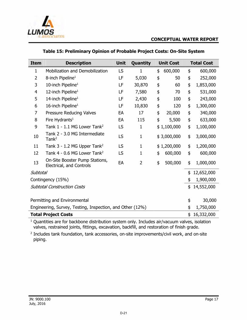
Preliminary opinions of probable project costs for the recommended on-site and off-site water systems are presented in Tables 15 and 16.
D-20
CONCEPTUAL WATER REPORT
JN: 9000.100 Page 17 July, 2016
Table 15: Preliminary Opinion of Probable Project Costs: On-Site System
Item Description Unit Quantity Unit Cost Total Cost
1 Mobilization and Demobilization LS 1 $ 600,000 $ 600,000
2 8-inch Pipeline1 LF 5,030 $ 50 $ 252,000
3 10-inch Pipeline1 LF 30,870 $ 60 $ 1,853,000
4 12-inch Pipeline1 LF 7,580 $ 70 $ 531,000
5 14-inch Pipeline1 LF 2,430 $ 100 $ 243,000
6 16-inch Pipeline1 LF 10,830 $ 120 $ 1,300,000
7 Pressure Reducing Valves EA 17 $ 20,000 $ 340,000
8 Fire Hydrants1 EA 115 $ 5,500 $ 633,000
9 Tank 1 - 1.1 MG Lower Tank2 LS 1 $ 1,100,000 $ 1,100,000
10 Tank 2 - 3.0 MG Intermediate Tank2 LS 1 $ 3,000,000 $ 3,000,000
11 Tank 3 - 1.2 MG Upper Tank2 LS 1 $ 1,200,000 $ 1,200,000
12 Tank 4 - 0.6 MG Lower Tank2 LS 1 $ 600,000 $ 600,000
13 On-Site Booster Pump Stations, Electrical, and Controls
EA 2 $ 500,000 $ 1,000,000
Subtotal
$ 12,652,000
Contingency (15%)
$ 1,900,000
Subtotal Construction Costs
$ 14,552,000
Permitting and Environmental
$ 30,000
Engineering, Survey, Testing, Inspection, and Other (12%)
$ 1,750,000
Total Project Costs $ 16,332,000
1 Quantities are for backbone distribution system only. Includes air/vacuum valves, isolation valves, restrained joints, fittings, excavation, backfill, and restoration of finish grade.
2 Includes tank foundation, tank accessories, on-site improvements/civil work, and on-site piping.
D-21

CONCEPTUAL WATER REPORT
JN: 9000.100 Page 18 July, 2016
Table 16: Preliminary Opinion of Probable Project Costs: Off-Site System
Item Description Unit Quantity Unit Cost Total Cost
1 Mobilization and Demobilization LS 1 $ 400,000 $ 400,000
2 Furnish and Install 16" Pipeline1 LF 33,000 $ 150 $ 4,950,000
3 Connection to Existing 24" TMWA Main1 LS 1 $ 30,000 $ 30,000
4 Off-Site Booster Pump Station, Electrical, Controls, and Building
LS 1 $ 800,000 $ 800,000
5 Isolation Valves EA 8 $ 20,000 $ 160,000
6 Air/Vacuum Valves EA 3 $ 20,000 $ 60,000
Subtotal
$ 6,400,000
Contingency (15%)
$ 960,000
Subtotal Construction Costs
$ 7,360,000
Permitting and Environmental
$ 30,000
Engineering, Survey, Testing, Inspection, and Other (12%)
$ 890,000
Total Project Costs $ 8,280,000
1 Includes restrained joints, fittings, excavation, backfill, restoration of finish grade/pavement replacement, traffic control.
C. Permitting Requirements
Permits and approvals that will be required for construction of the on-site and off-site water systems will include, but not be limited to, the following:
� County Encroachment Permit � Nevada Department of Transportation (NDOT) Right-of-Way Occupancy Permit � Nevada Division of Environmental Protection (NDEP) Bureau of Safe Drinking Water
Application for Approval of a Water Project � TMWA
D. Construction Considerations
Considerations for design and construction of the off-site water main are summarized below:
� Utility conflicts: A thorough investigation of existing utilities along the water main alignment will need to be conducted during design including review of record drawings, coordination with utility companies, and potentially potholing.
� Special construction: Special construction (e.g. concrete encasement) may be required if minimum utility separations cannot be met within existing utility corridors.
D-22

CONCEPTUAL WATER REPORT
JN: 9000.100 Page 19 July, 2016
� Connection to existing system: Connection to the existing 24” TMWA water main in Lemmon Dr. and North Virginia St. (see Appendix A) will need to be coordinated and planned to minimize water service interruptions.
� Traffic control: Traffic control measures will need to be developed and implemented in accordance with the requirements of the County, NDOT, and the Manual on Uniform Traffic Control Devices.
� NDOT: Construction requirements and right-of-way occupancy permit terms will need to be incorporated into the design and considered for the project schedule.
X. CONCLUSIONS
The preliminary on-site water system includes a backbone distribution system with six pressure zones, pipe diameters ranging from 8 to 16-inch diameter, four phased water storage tanks, and two booster pump stations to boost water to higher pressure zones. Hydraulic modeling results and calculations show that conceptual StoneGate water distribution system will be in compliance with all state and local regulations to meet required ADD, MDD, fire flow, and PHD scenarios. The preliminary off-site water system is sized to provide a MDD of approximately 3,207 gpm for Phases 1 through 5 of the StoneGate community and includes 33,000 LF of 16-inch water main and an off-site booster pump station to be constructed prior to Phase 3. Reduction of potable water demands and addition of supplemental water supply (e.g. Red Rock Road) could result in a smaller water main diameter and/or higher flow capacity.
D-23

CONCEPTUAL WATER REPORT
JN: 9000.100 Page 20 July, 2016
XI. REFERENCES
[1] Truckee Meadows Water Authority, Guidelines for Estimating Maximum Day Demands, 14 August 2013.
[2] Office of Energy Efficiency & Renewable Energy, Federal Water Use Indices (Source: American Water Works Association 1996), May 2016. <http://energy.gov/eere/femp/federal-water-use-indices>
[3] Morales, Miguel A., Martin, Jacqueline M., Heaney, James P., University of Florida, and
Conserve Florida Water Clearinghouse. “Methods for Estimating Commercial, Industrial, and Institutional Water Use”. 2009 FSAWWA Water Conference, Orlando, FL.
[4] Truckee Meadows Water Authority, Section 1.1. Designing Water Distribution Facilities –
Design Standards, July 2011.
D-24

FIGURES
D-25

WWW.LUMOSINC.COM
DATE:DRAWN BY:DESIGNED BY:CHECKED BY:
CIVIL ENGINEERINGGEOTECHNICAL ENGINEERINGPLANNINGLANDSCAPE ARCHITECTURESURVEYING / GISCONSTRUCTION SERVICESMATERIALS TESTING
BYD
ESC
RIP
TIO
ND
ATE
REV
JOB NO.:
FAX (775) 883-7114TEL (775) 883-7077CARSON CITY, NEVADA 89706800 EAST COLLEGE PARKWAY
HEI
NZ
RAN
CH
LAN
D C
OM
PAN
Y, L
LC
STO
NEG
ATE
MAS
TER
PLA
NN
ED C
OM
MU
NIT
YST
ON
EGAT
E PR
ELIM
NAR
Y LO
T PR
OG
RAM
FIG
UR
E 1
15/11/2016
MB
9000.100
REN
OW
ASH
OE
NEV
ADA
D-26
Service Layer Credits: Source: Esri,DigitalGlobe, GeoEye, Earthstar Geographics,CNES/Airbus DS, USDA, USGS, AEX,Getmapping, Aerogrid, IGN, IGP, swisstopo,and the GIS User Community
UTUT
UT
UT
Tank 3
Tank 2
Tank 4
Tank 1
Phase 4
Phase 2
Phase 3
Phase 1
Phase 5
9222 PROTOTYPE DRIVERENO, NEVADA 89521TEL (775) 827-6111FAX (775) 827-6122
WWW.LUMOSINC.COM
CIVIL ENGINEERINGGEOTECHNICAL ENGINEERINGPLANNINGLANDSCAPE ARCHITECTURESURVEYING/GISCONSTRUCTION SERVICESMATERIALS TESTING
HE
INZ
RA
NC
H L
AN
D C
OM
PAN
Y, L
LC
RE
NO
NE
VAD
A
STO
NE
GAT
E M
ASTE
R P
LAN
NE
D C
OM
MU
NIT
YPR
ELIM
INA
RY
TAN
K LO
CAT
ION
SAN
D S
ERV
ICE
ARE
ASFI
GU
RE
2
DATE:
DRAWN BY:
SCALE:
JOB NO:
6/17/2016
ILM
1:14,000
9000.100
RE
VD
ATE
DE
SC
RIP
TIO
NB
Y
WA
SH
OE
Tank 4
Tank 3
Tank 2
Tank 1
Pressure Zones
0 0.25 0.5 0.75 10.125Miles
¹ 2
Pressure Zone 1
Pressure Zone 2
Pressure Zone 3
Pressure Zone 4
Pressure Zone 5
Pressure Zone 6
D-27

Service Layer Credits: Source: Esri,DigitalGlobe, GeoEye, Earthstar Geographics,CNES/Airbus DS, USDA, USGS, AEX,Getmapping, Aerogrid, IGN, IGP, swisstopo,and the GIS User Community
=
=
UTUT
UT
UT
!(
!(
!(
!(
!(
!(
!(
!(
!(
!(
!(
!(
!(
!(
!(
!(
!(
!(
Tank 3
Tank 2
Tank 4
Tank 1
Pump
Pump
Phase 4
Phase 2
Phase 3
Phase 1
Phase 5
Potential FutureUtility Connection
Potential FutureUtility Connection
9222 PROTOTYPE DRIVERENO, NEVADA 89521TEL (775) 827-6111FAX (775) 827-6122
WWW.LUMOSINC.COM
CIVIL ENGINEERINGGEOTECHNICAL ENGINEERINGPLANNINGLANDSCAPE ARCHITECTURESURVEYING/GISCONSTRUCTION SERVICESMATERIALS TESTING
HE
INZ
RA
NC
H L
AN
D C
OM
PAN
Y, L
LC
RE
NO
NE
VAD
A
STO
NE
GAT
E M
ASTE
R P
LAN
NE
D C
OM
MU
NIT
YPR
ELIM
INA
RY
DIS
TRIB
UTI
ON
MAP
FIG
UR
E 3
DATE:
DRAWN BY:
SCALE:
JOB NO:
6/17/2016
ILM
1:14,000
9000.100
RE
VD
ATE
DE
SC
RIP
TIO
NB
Y
WA
SH
OE
0 0.25 0.5 0.75 10.125Miles
¹
!( Pressure Reducing Valve
8" Water Main
14" Water Main
12" Water Main
10" Water Main
3
16" Water Main
D-28

Image courtesy of USGS Image courtesy of the Nevada State Mapping Advisory Committee Earthstar Geographics SIO © 2016 Microsoft Corporation Image courtesy of USGS Image courtesy of the Nevada State Mapping Advisory Committee Earthstar Geographics SIO © 2016 Microsoft Corporation
Image courtesy of USGS Image courtesy of the Nevada State Mapping Advisory Committee Earthstar Geographics SIO © 2016 Microsoft Corporation Image courtesy of USGS Image courtesy of the Nevada State Mapping Advisory Committee Earthstar Geographics SIO © 2016 Microsoft Corporation
WWW.LUMOSINC.COM
DATE:DRAWN BY:DESIGNED BY:CHECKED BY:
CIVIL ENGINEERINGGEOTECHNICAL ENGINEERINGPLANNINGLANDSCAPE ARCHITECTURESURVEYING / GISCONSTRUCTION SERVICESMATERIALS TESTING
BYD
ESC
RIP
TIO
ND
ATE
REV
JOB NO.:
FAX (775) 883-7114TEL (775) 883-7077CARSON CITY, NEVADA 89706800 EAST COLLEGE PARKWAY
HEI
NZ
RAN
CH
LAN
D C
OM
PAN
Y, L
LC
STO
NEG
ATE
MAS
TER
PLA
NN
ED C
OM
MU
NIT
YPR
ELIM
INAR
Y O
FF-S
ITE
WAT
ER S
YSTE
MFI
GU
RE
4
4MAY, 2016
KTKTTR
9000.400
REN
OW
ASH
OE
NEV
ADA
LEGEND
SCALE: 1" =
FOR SHEET SIZE: GRAPHIC SCALE
0 260013002600 5200
5200'
11" x 17"
D-29

APPENDICES
D-30

Appendix A
Construction Drawing for 24” TMWA Main in North Virginia Street
D-31

D-32

Appendix B
Irrigation Calculations
D-33

LANDSCAPE WATER USE CALCULATIONS
Project Name: StoneGate Phase 1 - Reclaimed water use
Date: 4-7-16
assumption:Drip System: 1 gallon per hour emitters -
(1/1 gal. plant; 2/5 gal. plant; 3/15 gal. plant; 4/24" box plant)
no.of plants 7113 1 gal shrubs (x1)2371 5 gal shrubs (x2)797 Small trees (x3)
1700 Large trees (x4)= 21,046 drip emitters @ 1 gphx 4 hours (4 hours per day)= 84184 gallons per dayx 64 waterings (twice/week x 32 weeks)= 5387776 gallons per year
5387776 total gallons per year/ 325851 gallons per acre foot
= 16.534 acre feet per year
Lawn/ Grasses
New Turf Area 41,822 Area (SF)x 2 Inches per Weekx 32 Weeks per year= 5.1205387 acre feet per year
Pasture Grasses 96,000 Area (SF)x 0.5 Inches per Weekx 32 Weeks per year/ 2.9384757 acre feet per year
8.0590144 acre feet per year
LS H20 Use Calc.-100%-12-18-03.xls Page 1D-34

LANDSCAPE WATER USE CALCULATIONS
Project Name: StoneGate Phase 2 - Reclaimed water use
Date: 4-21-16 update
assumption:Drip System: 1 gallon per hour emitters -
(1/1 gal. plant; 2/5 gal. plant; 3/15 gal. plant; 4/24" box plant)
no.of plants 12,454 1 gal shrubs (x1)4,150 5 gal shrubs (x2)1476 Small trees (x3)2723 Large trees (x4)
= 36,074 drip emitters @ 1 gphx 4 hours (4 hours per day)= 144296 gallons per dayx 64 waterings (twice/week x 32 weeks)= 9234944 gallons per year
9234944 total gallons per year/ 325851 gallons per acre foot
= 28.341 acre feet per year
Lawn/ Grasses
New Turf Area 265,906 Area (SF)x 2 Inches per Weekx 32 Weeks per year= 32.556596 acre feet per year
Pasture Grasses 447,500 Area (SF)x 0.5 Inches per Weekx 32 Weeks per year/ 13.697582 acre feet per year
46.254178 acre feet per year
LS H20 Use Calc.-100%-12-18-03.xls Page 1D-35

LANDSCAPE WATER USE CALCULATIONS
Project Name: StoneGate Phase 3 - Reclaimed water use
Date: 4-7-16
assumption:Drip System: 1 gallon per hour emitters -
(1/1 gal. plant; 2/5 gal. plant; 3/15 gal. plant; 4/24" box plant)
no.of plants 4827 1 gal shrubs (x1)1609 5 gal shrubs (x2)388 Small trees (x3)910 Large trees (x4)
= 12,849 drip emitters @ 1 gphx 4 hours (4 hours per day)= 51396 gallons per dayx 64 waterings (twice/week x 32 weeks)= 3289344 gallons per year
3289344 total gallons per year/ 325851 gallons per acre foot
= 10.095 acre feet per year
Lawn/ Grasses
New Turf Area 37,270 Area (SF)x 2 Inches per Weekx 32 Weeks per year= 4.5632078 acre feet per year
Pasture Grasses 166,820 Area (SF)x 0.5 Inches per Weekx 32 Weeks per year/ 5.1062137 acre feet per year
9.6694215 acre feet per year
LS H20 Use Calc.-100%-12-18-03.xls Page 1D-36

LANDSCAPE WATER USE CALCULATIONS
Project Name: StoneGate Phase 4 - Reclaimed water use
Date: 4-7-16
assumption:Drip System: 1 gallon per hour emitters -
(1/1 gal. plant; 2/5 gal. plant; 3/15 gal. plant; 4/24" box plant)
no.of plants 4498 1 gal shrubs (x1)1500 5 gal shrubs (x2)653 Small trees (x3)653 Large trees (x4)
= 12,069 drip emitters @ 1 gphx 4 hours (4 hours per day)= 48276 gallons per dayx 64 waterings (twice/week x 32 weeks)= 3089664 gallons per year
3089664 total gallons per year/ 325851 gallons per acre foot
= 9.482 acre feet per year
Lawn/ Grasses
New Turf Area 0 Area (SF)x 2 Inches per Weekx 32 Weeks per year= 0 acre feet per year
Pasture Grasses 109,250 Area (SF)x 0.5 Inches per Weekx 32 Weeks per year/ 3.3440465 acre feet per year
3.3440465 acre feet per year
LS H20 Use Calc.-100%-12-18-03.xls Page 1D-37

LANDSCAPE WATER USE CALCULATIONS
Project Name: StoneGate Phase 5 - Reclaimed water use
Date: 4-22-16 update
assumption:Drip System: 1 gallon per hour emitters -
(1/1 gal. plant; 2/5 gal. plant; 3/15 gal. plant; 4/24" box plant)
no.of plants 2480 1 gal shrubs (x1)826 5 gal shrubs (x2)165 Small trees (x3)386 Large trees (x4)
= 6,171 drip emitters @ 1 gphx 4 hours (4 hours per day)= 24684 gallons per dayx 64 waterings (twice/week x 32 weeks)= 1579776 gallons per year
1579776 total gallons per year/ 325851 gallons per acre foot
= 4.848 acre feet per year
Lawn/ Grasses
New Turf Area 13,983 Area (SF)x 2 Inches per Weekx 32 Weeks per year= 1.7120294 acre feet per year
Pasture Grasses 0 Area (SF)x 0.5 Inches per Weekx 32 Weeks per year/ 0 acre feet per year
1.7120294 acre feet per year
LS H20 Use Calc.-100%-12-18-03.xls Page 1D-38

LANDSCAPE WATER USE CALCULATIONS
Project Name: StoneGate North Parcel Water Use
Date: 4-20-16
assumption:Drip System: 1 gallon per hour emitters -
(1/1 gal. plant; 2/5 gal. plant; 3/15 gal. plant; 4/24" box plant)
no.of plants 21600 1 gal shrubs (x1)7200 5 gal shrubs (x2)1440 Small trees (x3)3360 Large trees (x4)
= 53,760 drip emitters @ 1 gphx 4 hours (4 hours per day)= 215040 gallons per dayx 64 waterings (twice/week x 32 weeks)= 13762560 gallons per year
13762560 total gallons per year/ 325851 gallons per acre foot
= 42.236 acre feet per year
Lawn/Spray System
New Turf Area 899,079 Area (SF)x 2 Inches per Weekx 32 Weeks per year= 110.08007 acre feet per year
Existing Turf Area Area (SF)x 2 Inches per Weekx 32 Weeks per year/ 0 acre feet per year
110.08007 acre feet per year
LS H20 Use Calc.-100%-12-18-03.xls Page 1D-39

Appendix C
Water Main Calculations
D-40

Water Demands Roughness Coefficient 'C' 130
MDD for Phase 1 (gpm) 656 MDD for Phase 4 (gpm) 661
MDD for Phase 2 (gpm) 927 MDD for Phase 5 (gpm) 434
MDD for Phase 3 (gpm) 529 Total MDD (gpm) 3,207
Pipe Segment
Pipe
Length
(LF)
Pipe
Diameter
(in)
StoneGate
Demand
(gpm)
Additional
Demand
(gpm)
Velocity1
(fps)
HGL @
Start2 (ft)
HGL @
End2
(ft)
Ground/Tank
HWL Elevation
@ End (ft)
Pressure @
End2 (psi)
1: Ex. 30" Main (Matterhorn to Lemmon) 21,000 30 3,207 1,600 2.0 5,515 5,506 4,928 250
2: TMWA 24" Main (Lemmon to N.
Virginia)27,000 24 3,207 0 2.1 5,506 5,489 5,220 117
3: New Main to StoneGate Entrance (along
Hwy 395)33,000 16 3,207 0 4.7 5,489 5,448 5,110 147
High Point along Hwy 395 - 16 3,207 0 4.7 - 5,482 5,430 22.6
4: On-Site Water Main to Lower Tank Road
Intersection2,200 16 3,207 0 4.7 5,448 5,438 5,128 135
5: On-Site Water Main to Intermediate
Tank HWL (from end of Segment 4)8,000 16 2,117 0 3.1 5,438 5,422 5,420 1
6: On-Site Water Main to Lower Tank HWL
(from end of Segment 4)2,000 14 1,090 0 2.1 5,438 5,436 5,320 50
1 Velocities assuming ductile iron pipe for inner pipe diameters.
2 HGL and pressures for segments 3-6 include booster pumping along US395.
APPENDIX C
STONEGATE MASTER PLANNED COMMUNITY
CONCEPTUAL WATER REPORT
PRELIMINARY WATER MAIN CALCULATIONS WITH BOOSTER PUMPING
6/17/2016 C-1 L:\LAProj\9000.400 - Stonegate Offsite Engineering\Civil\Water\water main sizing
D-41
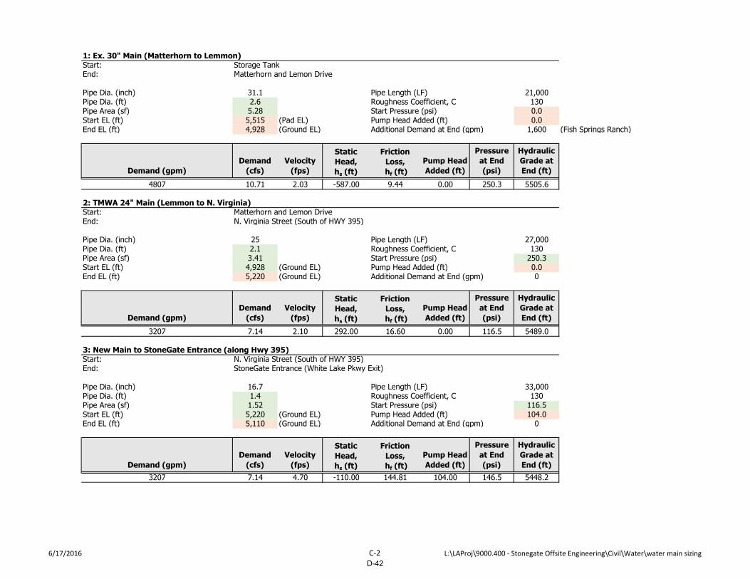
1: Ex. 30" Main (Matterhorn to Lemmon)Start: Storage Tank End: Matterhorn and Lemon Drive
Pipe Dia. (inch) 31.1 Pipe Length (LF) 21,000Pipe Dia. (ft) 2.6 Roughness Coefficient, C 130Pipe Area (sf) 5.28 Start Pressure (psi) 0.0Start EL (ft) 5,515 (Pad EL) Pump Head Added (ft) 0.0End EL (ft) 4,928 (Ground EL) Additional Demand at End (gpm) 1,600 (Fish Springs Ranch)
Demand (gpm)
Demand
(cfs)
Velocity
(fps)
Static
Head,
hs (ft)
Friction
Loss,
hf (ft)
Pump Head
Added (ft)
Pressure
at End
(psi)
Hydraulic
Grade at
End (ft)
4807 10.71 2.03 -587.00 9.44 0.00 250.3 5505.6
2: TMWA 24" Main (Lemmon to N. Virginia)Start: Matterhorn and Lemon DriveEnd: N. Virginia Street (South of HWY 395)
Pipe Dia. (inch) 25 Pipe Length (LF) 27,000Pipe Dia. (ft) 2.1 Roughness Coefficient, C 130Pipe Area (sf) 3.41 Start Pressure (psi) 250.3Start EL (ft) 4,928 (Ground EL) Pump Head Added (ft) 0.0End EL (ft) 5,220 (Ground EL) Additional Demand at End (gpm) 0
Demand (gpm)
Demand
(cfs)
Velocity
(fps)
Static
Head,
hs (ft)
Friction
Loss,
hf (ft)
Pump Head
Added (ft)
Pressure
at End
(psi)
Hydraulic
Grade at
End (ft)
3207 7.14 2.10 292.00 16.60 0.00 116.5 5489.0
3: New Main to StoneGate Entrance (along Hwy 395)Start: N. Virginia Street (South of HWY 395)End: StoneGate Entrance (White Lake Pkwy Exit)
Pipe Dia. (inch) 16.7 Pipe Length (LF) 33,000Pipe Dia. (ft) 1.4 Roughness Coefficient, C 130Pipe Area (sf) 1.52 Start Pressure (psi) 116.5Start EL (ft) 5,220 (Ground EL) Pump Head Added (ft) 104.0End EL (ft) 5,110 (Ground EL) Additional Demand at End (gpm) 0
Demand (gpm)
Demand
(cfs)
Velocity
(fps)
Static
Head,
hs (ft)
Friction
Loss,
hf (ft)
Pump Head
Added (ft)
Pressure
at End
(psi)
Hydraulic
Grade at
End (ft)
3207 7.14 4.70 -110.00 144.81 104.00 146.5 5448.2
6/17/2016 C-2 L:\LAProj\9000.400 - Stonegate Offsite Engineering\Civil\Water\water main sizing
D-42

4: On-Site Water Main to Lower Tank Road IntersectionStart: StoneGate Entrance (White Lake Pkwy Exit)End: Intersection of Road to Lower Tank
Pipe Dia. (inch) 16.7 Pipe Length (LF) 2,200Pipe Dia. (ft) 1.4 Roughness Coefficient, C 130Pipe Area (sf) 1.52 Start Pressure (psi) 146.5Start EL (ft) 5,110 (Ground EL) Pump Head Added (ft) 0.0End EL (ft) 5,128 (Ground EL) Additional Demand at End (gpm) 0
Demand (gpm)
Demand
(cfs)
Velocity
(fps)
Static
Head,
hs (ft)
Friction
Loss,
hf (ft)
Pump Head
Added (ft)
Pressure
at End
(psi)
Hydraulic
Grade at
End (ft)
3207 7.14 4.70 18.00 9.65 0.00 134.5 5438.5
5: On-Site Water Main to Intermediate Tank HWL (from end of Segment 4)Start: Intersection of Road to Lower TankEnd: Intermediate Tank
Pipe Dia. (inch) 16.7 Pipe Length (LF) 8,000Pipe Dia. (ft) 1.4 Roughness Coefficient, C 130Pipe Area (sf) 1.52 Start Pressure (psi) 134.5Start EL (ft) 5,128 (Ground EL) Pump Head Added (ft) 0.0End EL (ft) 5,420 (Tank HWL) Additional Demand at End (gpm) 0
Demand (gpm)
Demand
(cfs)
Velocity
(fps)
Static
Head,
hs (ft)
Friction
Loss,
hf (ft)
Pump Head
Added (ft)
Pressure
at End
(psi)
Hydraulic
Grade at
End (ft)
2117 4.72 3.10 292.00 16.27 0.00 1.0 5422.2
6: On-Site Water Main to Lower Tank HWL (from end of Segment 4)Start: Intersection of Road to Lower TankEnd: Lower Tank
Pipe Dia. (inch) 14.7 Pipe Length (LF) 2,000Pipe Dia. (ft) 1.2 Roughness Coefficient, C 130Pipe Area (sf) 1.18 Start Pressure (psi) 134.5Start EL (ft) 5,128 (Ground EL) Pump Head Added (ft) 0.0End EL (ft) 5,320 (Tank HWL) Additional Demand at End (gpm) 0
Demand (gpm)
Demand
(cfs)
Velocity
(fps)
Static
Head,
hs (ft)
Friction
Loss,
hf (ft)
Pump Head
Added (ft)
Pressure
at End
(psi)
Hydraulic
Grade at
End (ft)
1090 2.43 2.06 192.00 2.21 0.00 50.4 5436.3
6/17/2016 C-3 L:\LAProj\9000.400 - Stonegate Offsite Engineering\Civil\Water\water main sizing
D-43