Embed Size (px)
Citation preview
Evolution of the conceptual hydrogeologic and ground-water flow
model for Las Vegas Valley, Clark County, Nevada
David J. Donovan
Southern Nevada Water Authority
Geological Society of America Annual Meeting
November 14, 2000
Outline
• Model development
• Improvement in geologic understanding
Conceptual Model DevelopmentHydrologic Parameters
• Location, timing and value of:– Water levels– Ground water production / injection– Spring, creek flow– Major and minor wash flow– Water usage by bare-soil and pheatophytes– Natural recharge– Secondary recharge– Interbasin flow
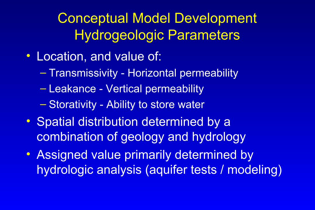
Conceptual Model DevelopmentHydrogeologic Parameters
• Location, and value of:– Transmissivity - Horizontal permeability– Leakance - Vertical permeability– Storativity - Ability to store water
• Spatial distribution determined by a combination of geology and hydrology
• Assigned value primarily determined by hydrologic analysis (aquifer tests / modeling)
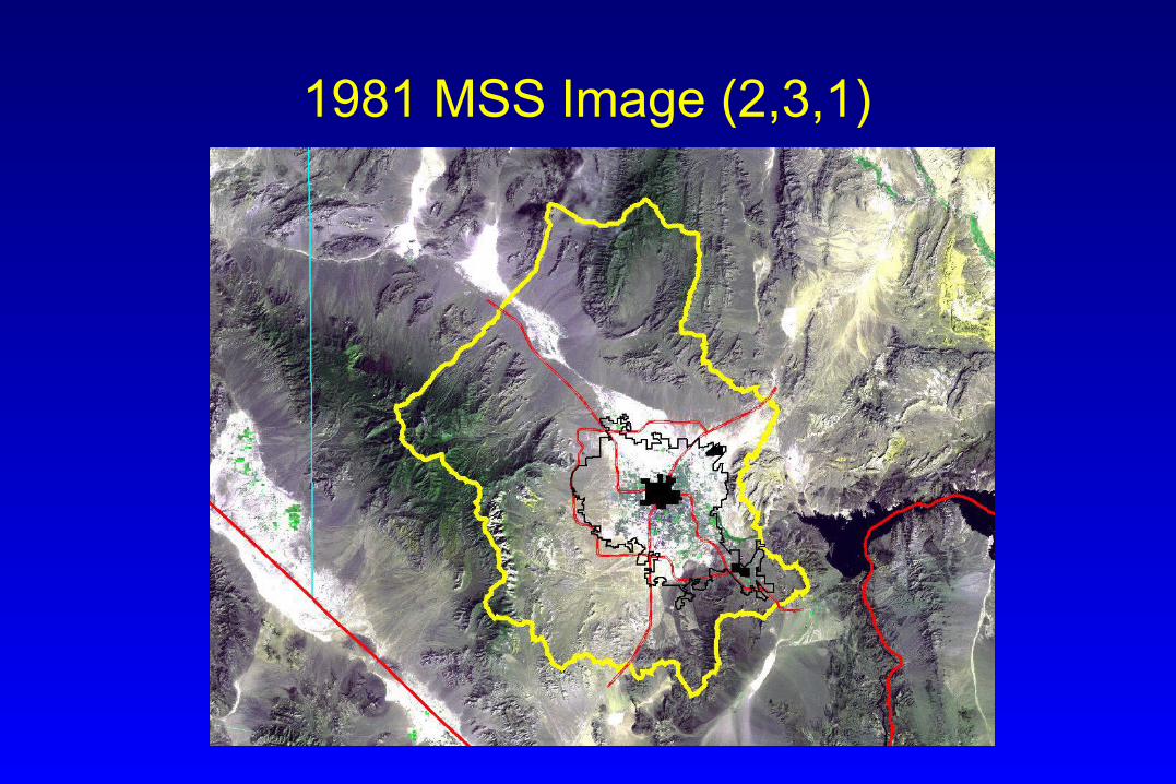
1981 MSS Image (2,3,1)
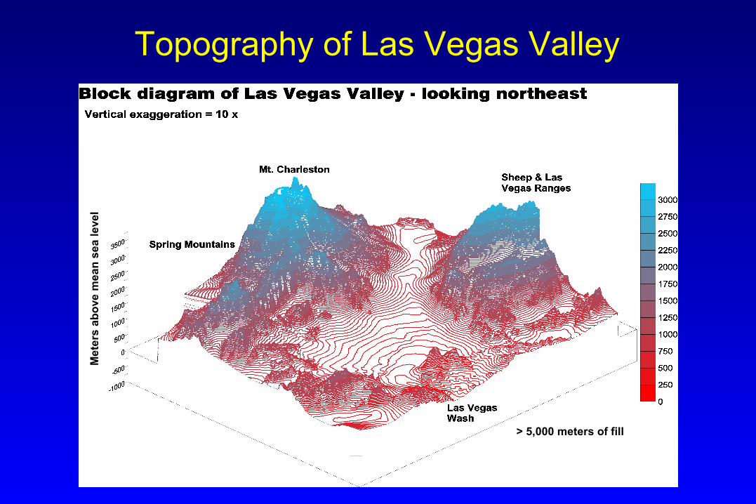
> 5,000 meters of fill
Me
ters
ab
ove
me
an
se
a l
eve
l
Topography of Las Vegas Valley
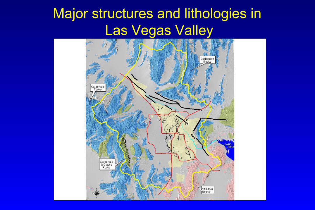
Major structures and lithologies in Las Vegas Valley
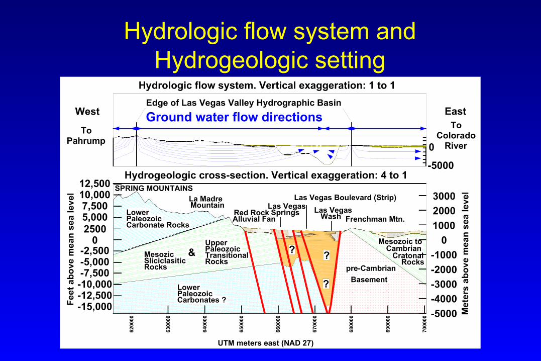
Hydrologic flow system and Hydrogeologic setting
-1000
-4000
-3000
-2000
-5000
2000
3000
0
1000LowerPaleozoicCarbonate Rocks
Carbonates ?PaleozoicLower
UpperPaleozoicTransitionalMesozic
SliciclasiticRocks
&Rocks Rocks
CratonalCambrian
Mesozoic to
?
pre-Cambrian
Basement
SPRING MOUNTAINS
Frenchman Mtn.Las Vegas
WashSpringsLas VegasMountain
La Madre
Alluvial FanRed Rock
Las Vegas Boulevard (Strip)
West EastEdge of Las Vegas Valley Hydrographic Basin
Ground water flow directions
0
-5000Hydrogeologic cross-section. Vertical exaggeration: 4 to 1
025005,0007,500
10,00012,500
-2,500-5,000-7,500
-10,000-12,500-15,000
??
UTM meters east (NAD 27)
Hydrologic flow system. Vertical exaggeration: 1 to 1
ToColorado
River
ToPahrump
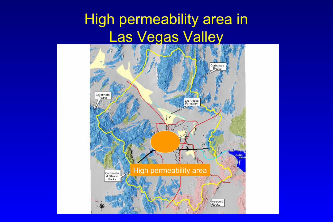
High permeability area inLas Vegas Valley
High permeability area
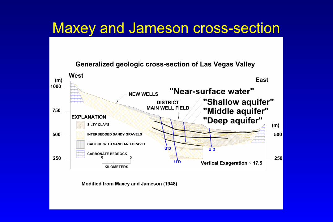
Maxey and Jameson cross-section
East
INTERBEDDED SANDY GRAVELS
SILTY CLAYS
CALICHE WITH SAND AND GRAVEL
DISTRICTMAIN WELL FIELD
NEW WELLS
Generalized geologic cross-section of Las Vegas Valley
EXPLANATION
Modified from Maxey and Jameson (1948)
Vertical Exageration ~ 17.5U D
U D U D
500
250
(m)
West
0 5
KILOMETERS
CARBONATE BEDROCK
500
250
750
1000(m)
"Near-surface water""Shallow aquifer""Middle aquifer""Deep aquifer"
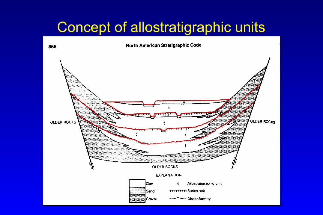
Concept of allostratigraphic units
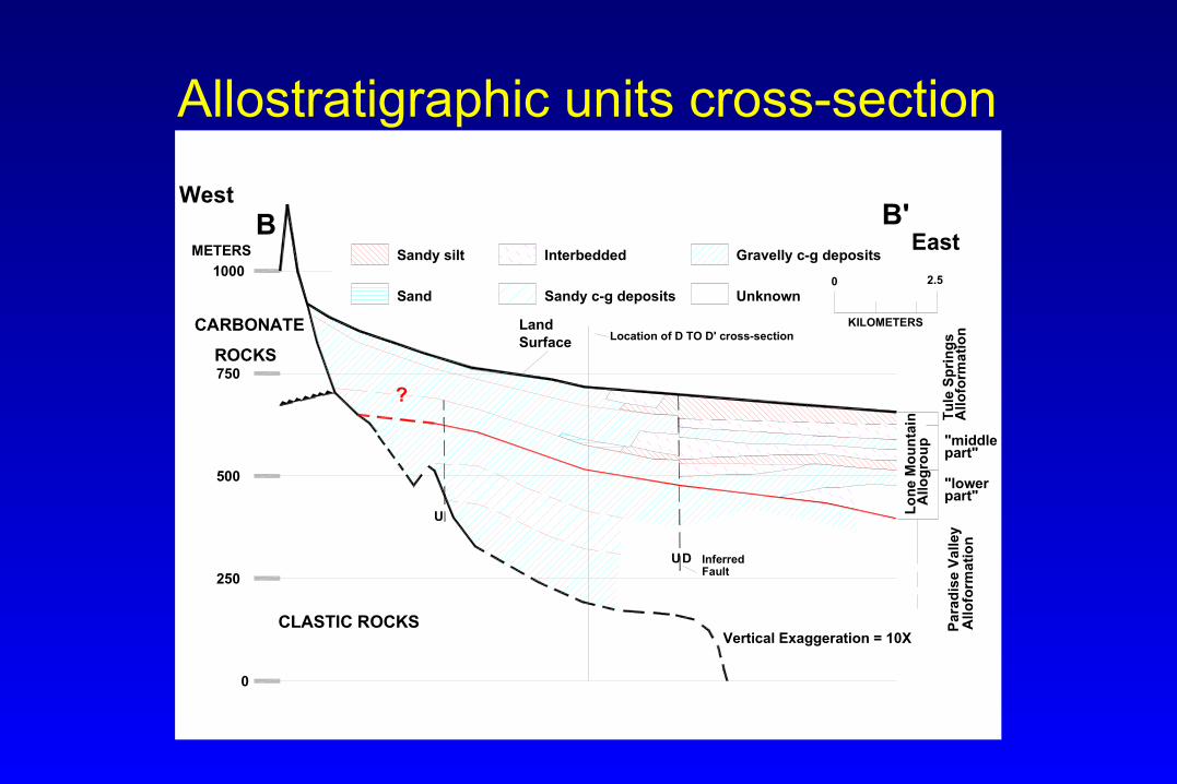
Allostratigraphic units cross-section
"middle
0
250
500
Fault
CLASTIC ROCKS
UD Inferred
U
part""lower
part"
CARBONATE
750
West
1000
METERS
B
?
Surface Location of D TO D' cross-section
Vertical Exaggeration = 10X
B'
Land
Sand Sandy c-g deposits
KILOMETERS
Gravelly c-g depositsInterbeddedSandy silt
2.50
ROCKS
Unknown
East
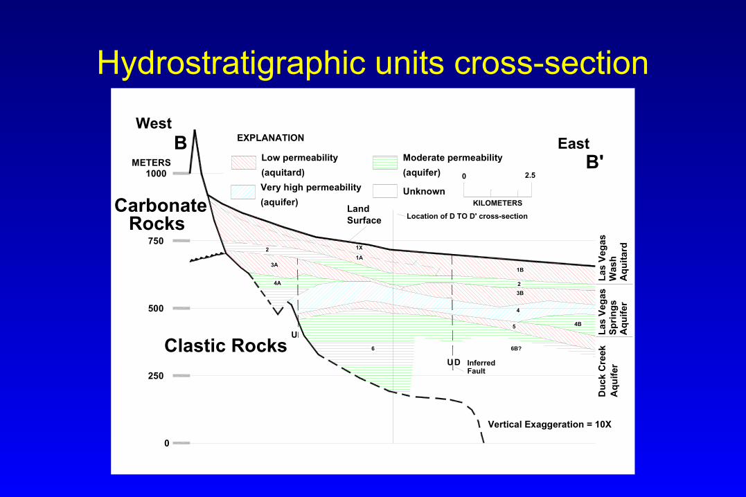
Hydrostratigraphic units cross-section
24A
0
250
500
Fault
5
6 6B?
UD Inferred
U
4
4B
3B
750
West
1000METERS
B
(aquifer)
(aquifer)(aquitard)
3A1B
2
1A
1X
East
Surface Location of D TO D' cross-section
Vertical Exaggeration = 10X
B'
Land
Very high permeability
Low permeability Moderate permeability
KILOMETERS
Unknown
2.50
EXPLANATION
CarbonateRocks
Clastic Rocks
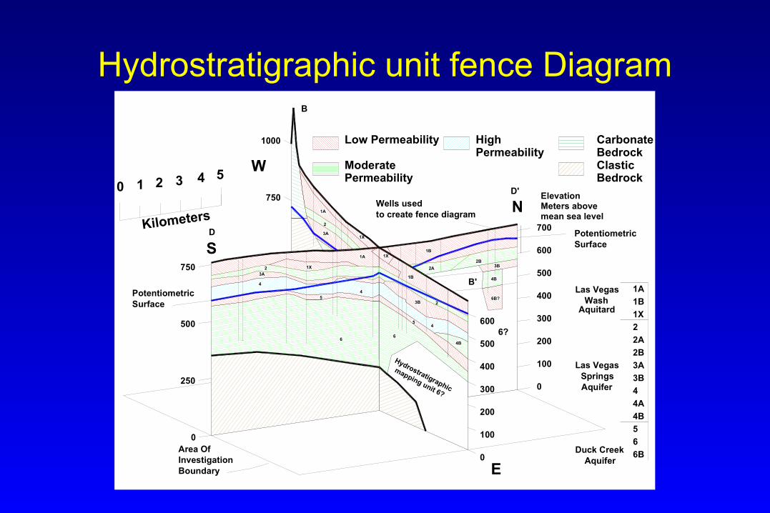
Hydrostratigraphic unit fence Diagram
1X1A
1B
1B
1A
1X
1X
4
4
4B
4B3A
2
5
66
5
3B 2
2
3A
2A
2B
4
6B?
3B
0 1 2 3 4 5
N
W
S
E
0
0
100
100
200
200
300
300
400
400
500
500
600
600
700
0
250
500
750
750
1000
Meters above
6?
Area OfInvestigationBoundary
D
D'
B
B'
Low Permeability
ModeratePermeability
HighPermeability
CarbonateBedrockClasticBedrock
PotentiometricSurface
Wells usedto create fence diagram
PotentiometricSurface
1A
1B
1X
2
2A
3A
3B
4
4A
4B
5
6
6B
2B
mean sea level
Elevation
Duck CreekAquifer
Las VegasSprings
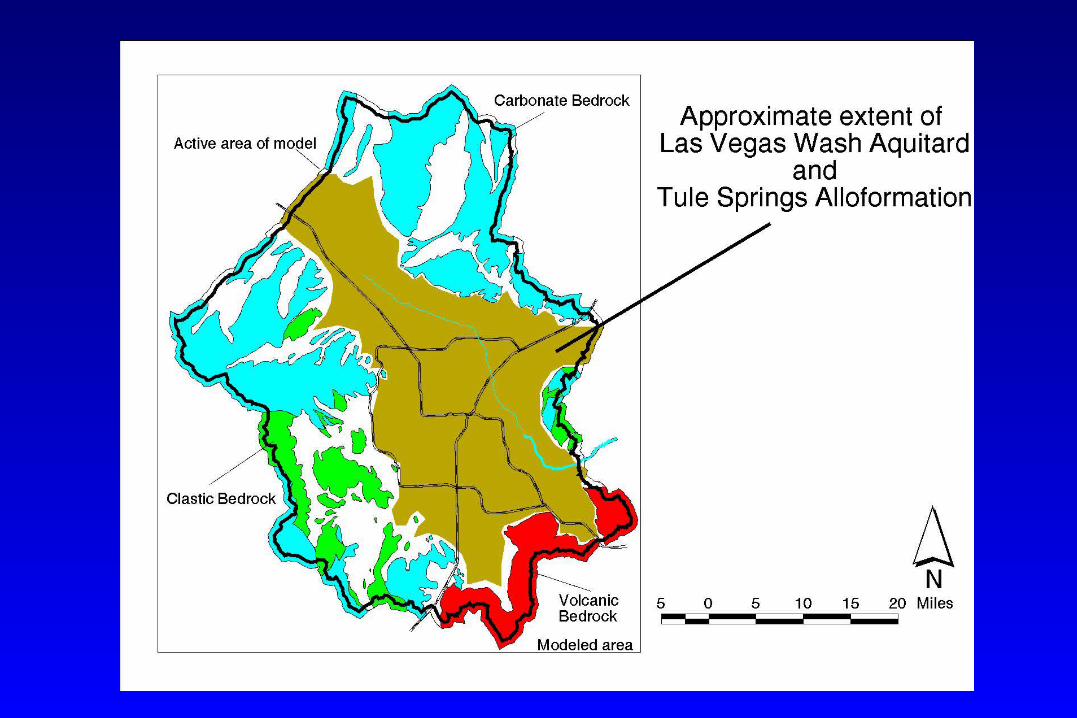
Las VegasWash
Aquifer
Aquitard
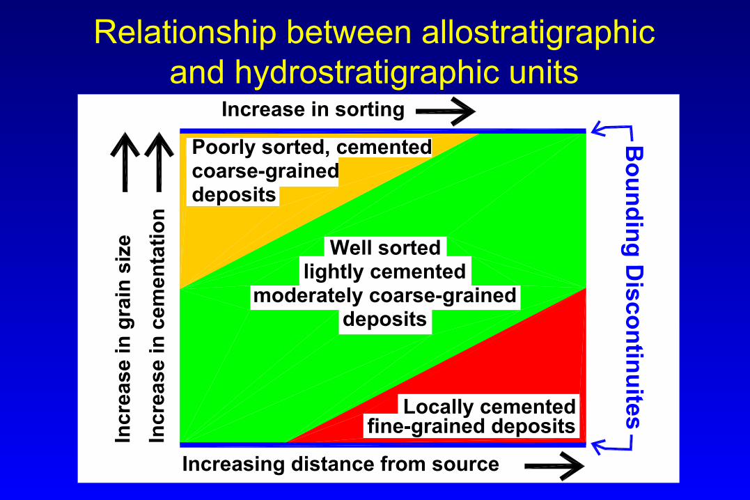
Relationship between allostratigraphic and hydrostratigraphic units
Increase in sorting
Increasing distance from source
Locally cemented
Poorly sorted, cementedcoarse-graineddeposits
Well sortedlightly cemented
moderately coarse-graineddeposits
fine-grained deposits
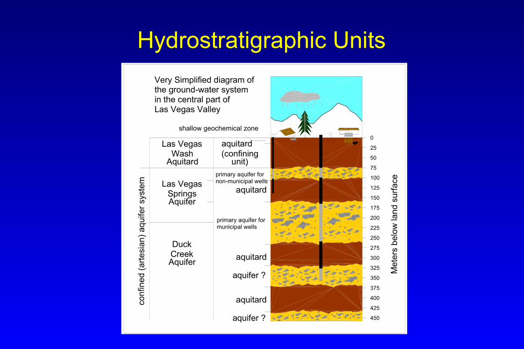
Hydrostratigraphic Units
shallow geochemical zone
aquitard
aquitard
aquitard
aquitard
primary aquifer fornon-municipal wells
primary aquifer formunicipal wells
aquifer ?
aquifer ?
Las VegasWash
Aquitard
Las VegasSpringsAquifer
DuckCreekAquifer
(confiningunit)
Very Simplified diagram ofthe ground-water systemin the central part ofLas Vegas Valley
0
25
50
75
100
125
150
175
200
225
250
275
300
325
350
375
400
425
450
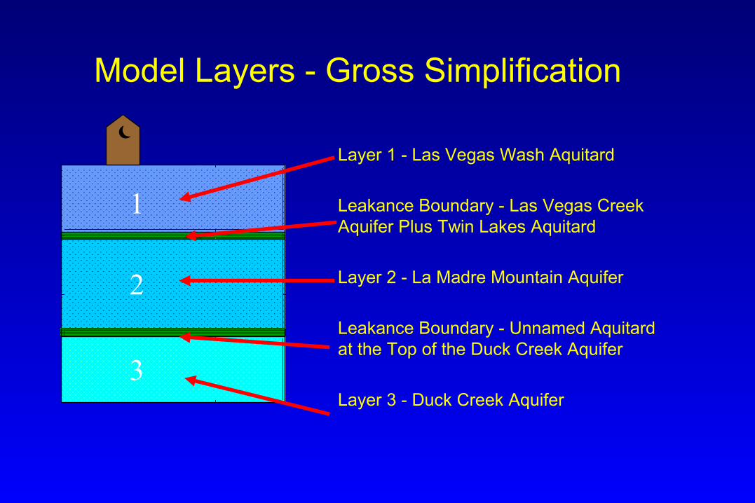
Model Layers - Gross Simplification
Layer 1 - Las Vegas Wash Aquitard
Leakance Boundary - Las Vegas Creek Aquifer Plus Twin Lakes Aquitard
Layer 2 - La Madre Mountain Aquifer
Leakance Boundary - Unnamed Aquitard at the Top of the Duck Creek Aquifer
Layer 3 - Duck Creek Aquifer
1
2
3
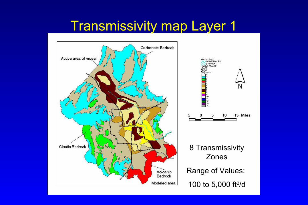
Transmissivity map Layer 1
8 Transmissivity Zones
Range of Values:
100 to 5,000 ft2/d

Upper Leakance layer
8 Leakance Zones
Range of Values:
1.0E-8 to 1.6E-4 ft2/d
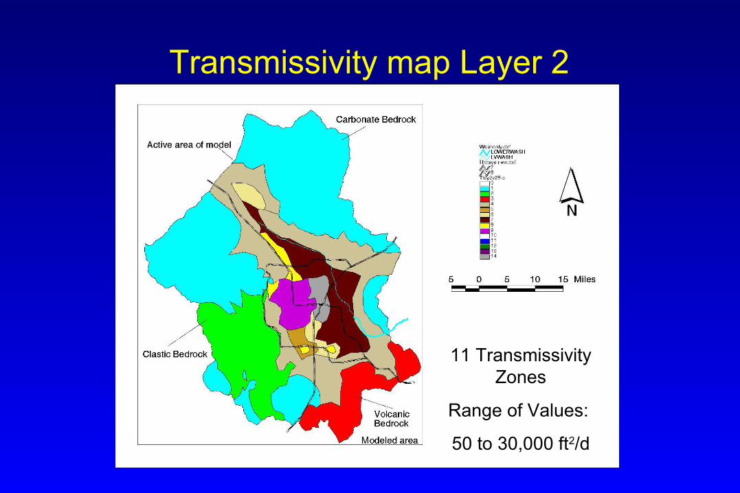
Transmissivity map Layer 2
11 Transmissivity Zones
Range of Values:
50 to 30,000 ft2/d
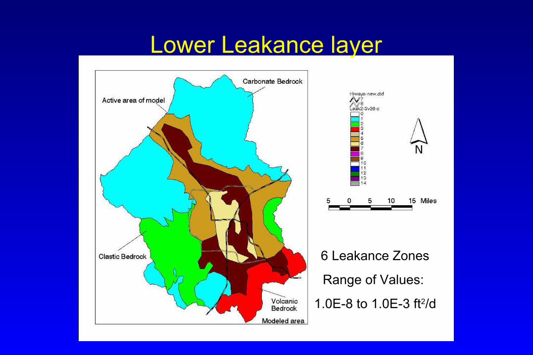
Lower Leakance layer
6 Leakance Zones
Range of Values:
1.0E-8 to 1.0E-3 ft2/d
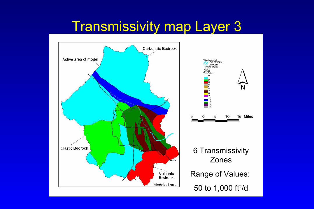
Transmissivity map Layer 3
6 Transmissivity Zones
Range of Values:
50 to 1,000 ft2/d
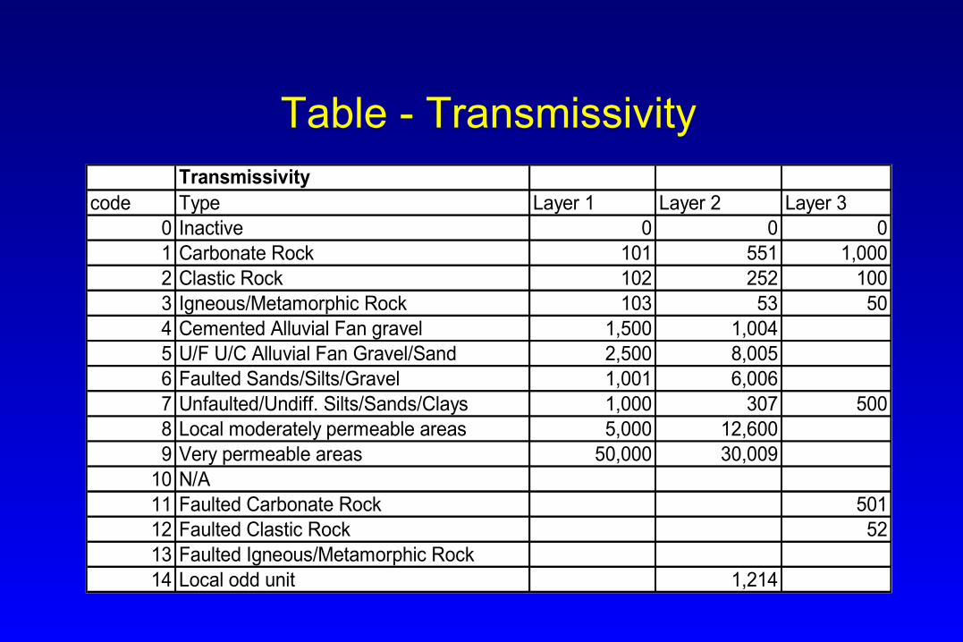
Table - TransmissivityTransmissivity
code Type Layer 1 Layer 2 Layer 30 Inactive 0 0 01 Carbonate Rock 101 551 1,0002 Clastic Rock 102 252 1003 Igneous/Metamorphic Rock 103 53 504 Cemented Alluvial Fan gravel 1,500 1,0045 U/F U/C Alluvial Fan Gravel/Sand 2,500 8,0056 Faulted Sands/Silts/Gravel 1,001 6,0067 Unfaulted/Undiff. Silts/Sands/Clays 1,000 307 5008 Local moderately permeable areas 5,000 12,6009 Very permeable areas 50,000 30,009
10 N/A11 Faulted Carbonate Rock 50112 Faulted Clastic Rock 5213 Faulted Igneous/Metamorphic Rock14 Local odd unit 1,214
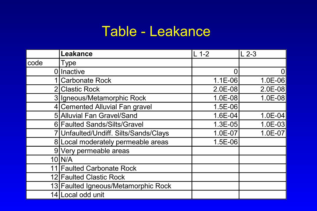
Table - Leakance
Leakance L 1-2 L 2-3code Type
0 Inactive 0 01 Carbonate Rock 1.1E-06 1.0E-062 Clastic Rock 2.0E-08 2.0E-083 Igneous/Metamorphic Rock 1.0E-08 1.0E-084 Cemented Alluvial Fan gravel 1.5E-065 Alluvial Fan Gravel/Sand 1.6E-04 1.0E-046 Faulted Sands/Silts/Gravel 1.3E-05 1.0E-037 Unfaulted/Undiff. Silts/Sands/Clays 1.0E-07 1.0E-078 Local moderately permeable areas 1.5E-069 Very permeable areas
10 N/A11 Faulted Carbonate Rock12 Faulted Clastic Rock13 Faulted Igneous/Metamorphic Rock14 Local odd unit
Conclusions
• Hydrologeologic models primarily test geologic concepts
• Geologic understanding has increased in the last two decades
• Hydrologic data is the compilation of causes and effects on the ground-water system
• Most observed ground-water system changes are a result of multiple causes
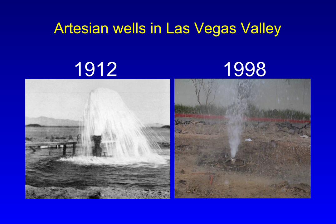
Artesian wells in Las Vegas Valley
1912 1998
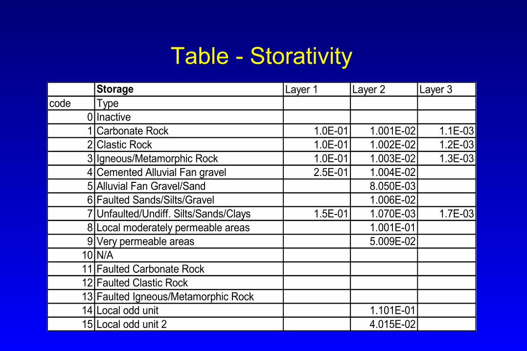
Table - StorativityStorage Layer 1 Layer 2 Layer 3
code Type0 Inactive1 Carbonate Rock 1.0E-01 1.001E-02 1.1E-032 Clastic Rock 1.0E-01 1.002E-02 1.2E-033 Igneous/Metamorphic Rock 1.0E-01 1.003E-02 1.3E-034 Cemented Alluvial Fan gravel 2.5E-01 1.004E-025 Alluvial Fan Gravel/Sand 8.050E-036 Faulted Sands/Silts/Gravel 1.006E-027 Unfaulted/Undiff. Silts/Sands/Clays 1.5E-01 1.070E-03 1.7E-038 Local moderately permeable areas 1.001E-019 Very permeable areas 5.009E-02
10 N/A11 Faulted Carbonate Rock12 Faulted Clastic Rock13 Faulted Igneous/Metamorphic Rock14 Local odd unit 1.101E-0115 Local odd unit 2 4.015E-02
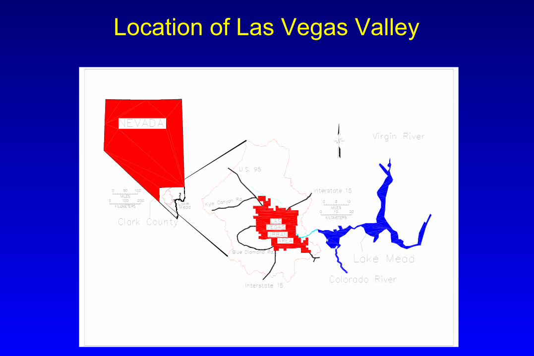
Location of Las Vegas Valley
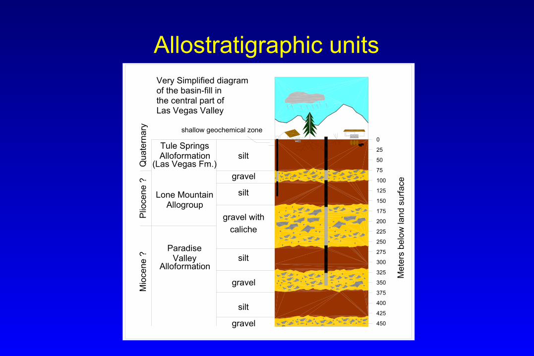
Allostratigraphic units
shallow geochemical zone
Tule SpringsAlloformation
Lone MountainAllogroup
ParadiseValley
Alloformation
silt
Very Simplified diagramof the basin-fill inthe central part ofLas Vegas Valley
0
25
50
75
100
125
150
175
200
225
250
275
300
325
350
375
400
425
450
gravel
silt
gravel with
silt
gravel
silt
gravel
caliche
(Las Vegas Fm.)
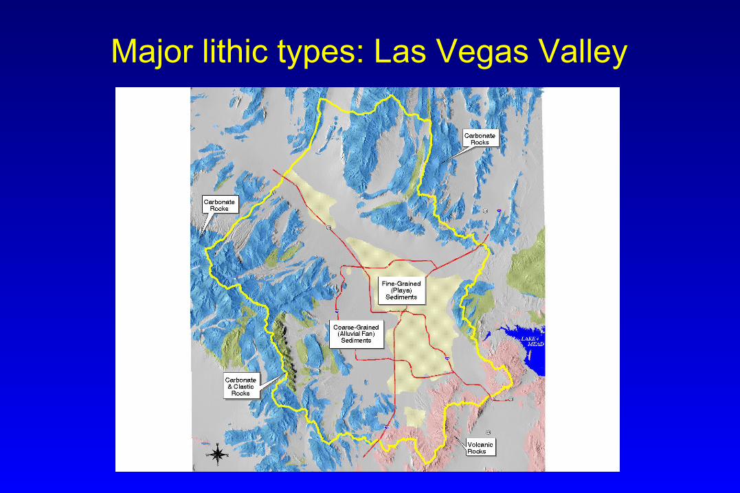
Major lithic types: Las Vegas Valley