Embed Size (px)
Citation preview
SECTION VII
CONCENTRATING BY GRAVITY METHODS

Chapter 40
THE SINK-FLOAT PROCESS I N LEAD-ZINC CONCENTRATION
bv E. N. Dovle
Actinp Sunerintendent, Su l l ivan Concentrator Comincn Ltd. , Kimberley, B. C . , Canada
Since t h e mid-1930's a number of p l a n t s , usinp t h e n r i n c i p l e s of h e a w media separa t ion , have been instalJ.ed throuphout the world. In cases involvinp: l ead , z inc o r lead-zinc o r e s the rea- sons f o r the choice of t h i s t y ~ e of benef ic ia t ion process have f a l l e n i n t o four major ca teaor ies :
A) The economic recovery of a d d i t i o n a l d i s t i n c t l y separa te vroducts, such a s dolomite l imestone a t the ?fascot P lan t (1) of t h e Amer- i can Zinc Co., and t h e f e r r o s i l i c o n produced by S t . Joseph Lead Company. (2)
B) The el iminat ion of a l a r e e por t ion of run-of-the-mine o r e p r i o r t o prindinp and f l o t a t i o n . t o a l low increased throuphput with low c a n i t a l c o s t . Examples of t h i s approach a r e the Levante and Ponente p l a n t s of the Montevecchio Comnany i n I t a l v (3) and the f requent choice of t h e Sink-Float nrocess by t h e Penarroya Comnanv of P a r i s .
C) The processine of a sedimentary deoos i t , i n which t h e valuable mineral is contained i n the matr ix separa t ing the boulders , a s was t h e case a t the S t . Joseph Lead Company p l a n t a t Haydon Creek (4) and a l s o a t Bunker H i l l Mininp and Smeltin?, Kellogr, Idaho.
D) The s i ~ p l i f i c a t i o n of eround support programs i n mines by allow- ing Kreater freedom of a c t i o n i n t h e e x t r a c t i v e p a t t e r n . An ex- ample of t h i s choice is Cominco's Su l l ivan p l a n t which came i n t o bein? a s p a r t of an extensive proposal t o update the mininp, crushinp. t r anspor ta t ion , gr indin? and b e n e f i c i a t i o n processes. (5)
HOW TO DETERMINE THE POTENTIAL OF SINK-FLOAT
Whatever the reason for selecting the Sink-Float process, it is, of course, essential that the physical properties essential to efficient separation exist in the material under consideration.
WHAT ORES CAN BE TREATED? ( 6 )
Any material can be treated in which there is a difference in specific gravity, between the valuable constituent and the waste, of at least 0.02, the separation can be effected in the specific gravity range of 1.25 to 3.40 and a clean separation between one constituent and the others is achieved by crushing to between 5 inch and 65 mesh. The latter size range is made possible by the use of cyclones similar to those used in the American Zinc Company Dyna-Whirlpool Process. Normally, in convential plants, the lower size range is between 4 and 10 mesh.
Under normal conditions all that is required to test any material for amenability to the Sink-Float process is: a supply of heavy medium, such as galena, ferrosilicon, magnetite, pyrite, heavy liquid chemical, etc., a series of sieves for screening different size fractions, and a few ordinary buckets or pails. With these simple tools, it is quite feasible to precisely determine the metallurgy that can be expected from any particular sample of ore at any level of specific gravity within the mixing range of the medium selected .
WHAT PROCESSES ARE AVAILABLE? (6)
The tvo major processes are the Heavy Media Separation prbcess, licensed by American Zinc Company and represented by American Cy- anamid Company, and the Sink-and-Float or H and H process, which is represented by Simon-Carves Ltd. in most countries throughout the world.
The former process generally utilizes a medium composed of ferrosilicon or magnetite, which is cleaned by magnetic separation, and the latter system uses eitherfine galena, which is cleaned by flotation, or, more recently, ferroeilicon-magnetite suspensions.
The equipment generally used in the H.M.S. process ranges from standard cones, utilizing air lifts for elevating the sink product, to drum separators, such as Western Machinery Company's Mobil-Mill,
and Akins spirals, which can produce a middling product if this is required. The H 6 H separator is basically a truncated pyramidal vessel, with an elevator fitted with self-draining buckets for positive sink removal.
The advantages of the drum separator are the ease of starting up or shutting down and power consumption savings.
PENARROYA
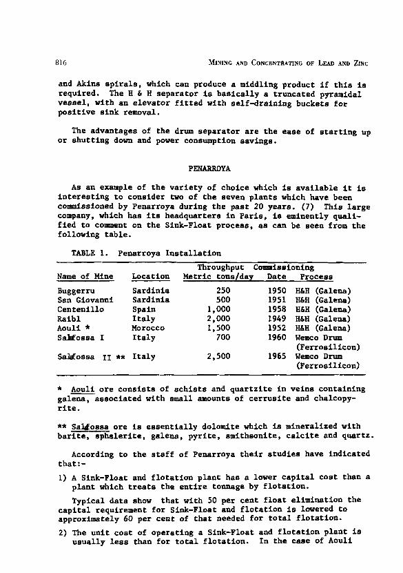
As an example of the variety of choice which is available it is interesting to consider two of the seven plants which have been commissioned by Penarroya during the past 20 years. (7) This large company, which has its headquarters in Paris, is eminently quali- fied to comment on the Sink-Float process, as can be seen from the following table.
TABLE 1. Penarroya Installation
Throughput Commissioning Name of Mine Location Metric tons/day Date Process
Buggerru Sardinia 250 1950 H6H (Galena) San Giovanni Sardinia 500 1951 HbH (Galena) Centenillo Spain 1,000 1958 H6H (Galena) Raibl Italy 2,000 1949 H6H (Galena) Aouli * Morocco 1,500 1952 HbH (Galena) Salcfossa I Italy 700 1960 Wemco Drum
(Ferrosilicon) SaMossa 11 ** Italy 2,500 1965 Wemco Drum
(Ferrosilicon)
* Aouli ore consists of schists and quartzite in veins containing galena, associated with emall amounts of cerrusite and chalcopy- rite.
** Sal&ossa ore is essentially dolomite which is mineralized vith barite, sphalerite, galena, pyrite, smithsonite, calcite and quartz.
According to the staff of Penarroya their studies have indicated that: - 1) A Sink-Float and flotation plant has a lower capital cost than a
plant which treats the entire tonnage by flotation.
Typical data show that with 50 per cent float elimination the capital requirement for Sink-Float and flotation is lowered to approximately 60 per cent of that needed for total flotation.
2) The unit cost of operating a Sink-Float and flotation plant is usually less than for total flotation. In the case of Aouli
the calculated cost r a t i o is $1.09 per ton versus $1.15 per ton, i n favour of pre-concentration by Sink-Float.
3) The use of heavy media separation na tura l ly involves some los s i n metal values. The f l o a t portion is generally extremely s t ab le while the sink-plus f i n e s represent the chemically a l t e r - able material which oxidizes f a i r l y rapidly. This means of course tha t the pre-concentrated f rac t ion must be treated a s rapidly a s possible t o avoid losses and that storage capacity must be somewhat limited. Indeed, i n the case of the f ines f rac t ion , it represents a possible upsetting influence i n the f l o t a t i o n c i r c u i t unless a la rge storage ag i t a to r is available fo r metering the f ines f r ac t ion to grinding on a continuous and even basis .
The f l o a t l o s s a t Aouli assays 0.32% lead and, by grinding and f lo t a t ion , 84% of t h i s metal can be recovered a t a grade of 70% Pb. The predicted treatment cost for t h i s f r ac t ion is high and, a t current metal prices, the decision t o i n s t a l l Sink-Float is still valid.
The primary considerations, which Penarroya list, a r e a s fol- love : - a) Capital cos t of plant and buildings b) Mesh of l i be ra t ion i n grinding C) Grindabil i ty of the ore d) Total recovery by e i the r method e ) Long term forecast of metal pr ices f ) Water and pover supply g) Tail ing disposal
Galena Versus Ferrosi l icon
Having decided tha t there a r e advantages t o preconcentration, the choice then has t o be made a s t o w h a t type of Sink-Float plant t o use. A t Penarroya both types of un i t s have been t r i ed , and they have developed a highly qual i ta t ive method of se lec t ing e i the r galena o r fer ros i l icon a s t h e i r choice of medium. (7)
In general, a mine such a s Aouli, with a feed grade of about 3.3 per cent lead, can supply su f f i c i en t medium from m i l l feed t o guarantee the trouble f r e e operation of an H & H plant. This is not the case a t Saltfossa 11, which has a feed grade of only 1.0 per cent lead and is primarily a zinc mine.
Studies car r ied out a t Penarroya's various propert ies have in- dicated t h a t the r e l a t i v e cos t of medium per ton t rea ted is 3.2 cents for galena and 1.7 cents for fer ros i l icon.
N.B. These f igures were based on L.M.E. prices fo r lead a t 100 Pounds Ster l ing per ton and "Knapsack" fer ros i l icon a t 24 cents per Kilo. (Knapsack fer ros i l icon is an atomized product which is

818 MINING AND CONCENTRATING OF LEAD AND ZINC
l e s s abrasive than t he normal crushed mater ial (9) ).
Control of both types of medium can be reasonably a t ta ined , bu t , according t o published da t a (8), t he use of f e r ro s i l i con brings a l eve l of automation t o a p lan t which is not poss ib le with galena medium.
Fie . 1 - Control Room - Salafossa 11
A s a r e s u l t of instrumentation, associated with the use of f e r ro s i l i con and the Wemco separator , Salafossa I1 enjoys a con- s iderab le advantage i n labour u t i l i z a t i o n over Aouli.
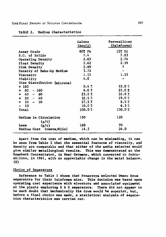
TABLE 2. Medium Characteristics
Assay Grade S.G. of Solids Operating Density Float Density Sink Density Density of Make-Up Medium Viscosity Stability Size Distribution (microns) + 160 + 80 - 160 + 40 - 80 + 20 - 40 + 10 - 20 - 10 Total
Medium in Circulation (g/t)
Loss (glt) Medium Cost (cente/Kilo)
Galena (Aouli)
80% Pb 7.4 2.65 2.62 2.69 3.72 1.15 4.0
Ferrosilicon (Salaf ossa)
15% Si 7.03 2.74 2.59
? - 1.15 -
Apart from the cost of medium, which can be misleading, it can be seen from Table 2 that the essential features of viscosity, and density are comparable and that either of the media selected would give similar metallurgical results. This was demonstrated at the Ramsbeck Concentrator, in West Germany, which converted to ferro- silicon, in 1961, with no appreciable change in the metal balance. (8)
Choice of Separators
Reference to Table 1 shows that Penarroya selected Wemco Drum separators for their Salafosga mine. This decision was based upon operating cost experience with elevators and associated equipment at the plants employing B 6 H separators. There did not appear to be much doubt that mechanically the drum would be superior, but, before a final choice was made, a statistical analysis of separa- tion characteristics was carried out.
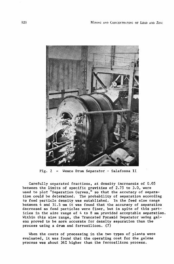
Fig. 2 - Wemco Drum Separator - Salafossa I1
Carefully separated fractions, at density increments of 0.05 between the limits of specific gravities of 2.75 to 3.0, were used to plot "Separation Curves," so that the accuracy of separa- tion could be determined. The probability of separation according to feed particle density was established. In the feed size range between 4 and 31.5 mm it was found that the accuracy of separation decreased as feed particles were finer, but in spite of this part- icles in the size range of 4 to 8 mu provided acceptable separation. Within this size range, the Truncated Pyramid Separator using gal- ena proved to be more accurate for density separation than the process using a drum and ferrosilicon. (7)
When the costs of processing in the two types of plants were evaluated, it was found that the operating cost for the galena process was about 36% higher than the ferrosilicon process.
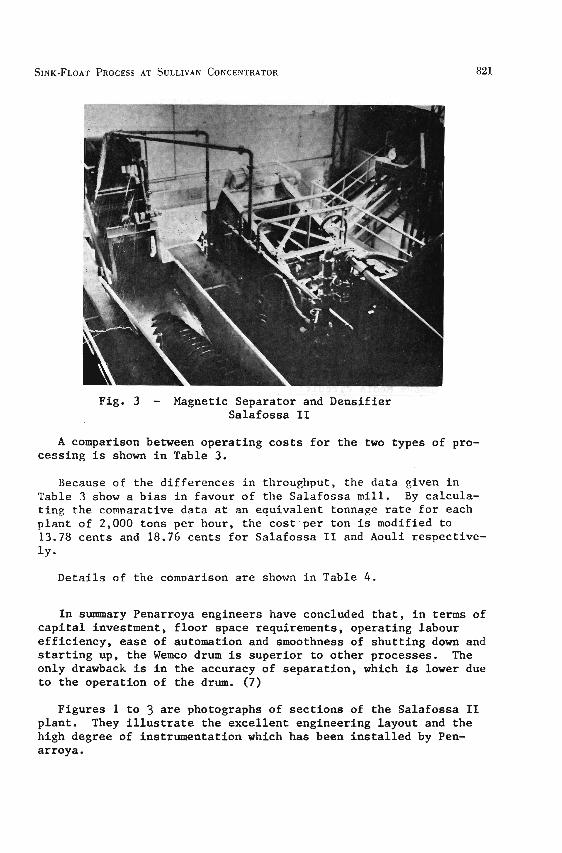
Fig. 3 - Magnetic Separator and Densifier Salafossa I1
A comparison between operating costs for the two types of pro- cessing is shown in Table 3.
Because of the differences in throughput, the data given in Table 3 show a bias in favour of the Salafossa mill. By calcula- ting the comparative data at an equivalent tonnage rate for each plant of 2,000 tons per hour, the cost.per ton is modified to 13.78 cents and 18.76 cents for Salafossa I1 and Aouli respective- ly-
Details of the comvarison are shown in Table 4.
In summary Penarroya engineers have concluded that, in terms of capital investment, floor space requirements, operating labour efficiency, ease of automation and smoothness of shutting down and starting up, the Wemco drum is superior to other processes. The only drawback is in the accuracy of separation, which is lower due to the operation of the drum. (7)
Figures 1 to 3 are photographs of sections of the Salafossa I1 plant. They illustrate the excellent engineering layout and the high degree of instrumentation which has been installed by Pen- arroya.
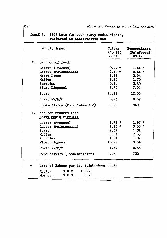
TABLE 3. 1968 Data for both Heavy Media Plants, evaluated in cents/metric ton
Hourly Input
I. per ton of feed:
Labour (Proceee) Labour (Maintenance) Motor Pover Medium Suppliee Float Dispoeal
Total
Power kW/h/ t
Productivity (Tone / w h i f t )
11. per ton treated into Heavy Media circuit:
Labour (Process) Labour (Maintenance) Power Medium Supplies Float Disposal
I Power kW/h/t
Galena Ferrosilicon (Aouli) (Salaf ossa) 65 t/h 93 t/h
1 Productivity (Tons/manshif t ) 293 7 00 I
1 * Cost of labour per day (eight-hour day) : 1 1 Italy: $ U.S. 13.87 1
~orocco: $ U.S. 5.02

TABLE 4. Comparative Operating Costs of a Wemco Plant using f e r ros i l i con and an a h H Plant using galena (Cents/ton)
H L H - Wemco
Operating Labour Repair Labour Parer Medium Supplies F loa t Disposal
WHAT TONNAGE RATES ARE POSSIBLE?
Ins t a l l ed capac i t i e s range from 5 tons per hour t o 450 tons per hour f o r lead-zinc appl ica t ions and a s high a s 800 tons per hour f o r diamond separat ion. There is r e a l l y no upper l i m i t bn the de- signed capaci ty, except f o r the a b i l i t y of t he mine t o provide s u f f i c i e n t feed t o maintain t he hourly r a t e .
ADVANTAGES AND DISADVANTAGES
Advantages
Some of the advantages have already been mentioned and they a l l trend towards: increased throughput, more f l e x i b i l i t y , lower sub- sequent treatment cos t s i n grinding and f l o t a t i o n , grea te r scope i n terms of acceptance of d i l u t i on i n mining and lower cos t of providing back f i l l . Naturally, unless t he process has a reasonable economic incentive, there is l i t t l e point i n incurr ing the cos t of the i n s t a l l a t i on . I n some cases there a r e o ther advantages which a r e unique t o t h e pa r t i cu l a r property i n question. For example, t a i l i n g disposal may be a ser ious problem because of l oca l regu- l a t i o n s regarding pol lut ion. However, the same volume of f l o a t could be stock-piled with no complaints from the au tho r i t i e s . Gen- e r a l l y speaking, t he process re-uses water qu i t e adequately and i t is common prac t ice t o u t i l i z e t he same water i n four o r f i v e s tages of the separat ion process, without the use of a thickener. (10)
Under most condit ions it is possible t o bring the p lan t under reasonably e f f ec t ive automatic cont ro l , and noise, which was form- e r l y a considerable nuisance, can be reduced by the use of rubber screens, sound a t tenuat ing mater ia l s i n cont ro l room walls , e tc .
Disadvant-
From the foregoing, it would appear that w concentrator should be without its own Sink-Float plant. This is hardly the case,and most operators vill agree that there are some serious disadvantages which could manifest themselves.
Listed in rather abstract order these are:-
1) Medium "fouling" can happen very rapidly, particularly vith galena, and the supply of medium can run out. This, of course, shuts the plant down until the medium is cleaned up again.
The best way of avoiding this situation is to provide a better than adequate vash to the feed entering the separator. Efficient slime removal is 95 per cent of the solution. If washing is a difficult proposition, then pre-cycloning of the fouled medium, prior to flotation cleaning, will produce a rapid improvement in medium stability and viscosity. N.B. With magnetite or ferro- silicon medium this problem does not really exist.
2) Disposal of the vaste product, usually the float, can present difficulties particularly in severe climatic conditions.
3) There is inevitably some loss of medium, regardless of washing efficiency, and this of course represents a cost item.
4) Precise control of the separation density is a pre-requisite to economic operation. Metal losses to float can become excessive and these are usually non-recoverable.
5) The equipment is generally subjected to high wear and mainten- ance is a major cost consideration.
6) Allied with the high maintenance cost is lower than normal op- erating availability, or high cost stand-by provision to obtain maximum operating time from the plant.
7) Extra operators are required and clean-up is a problem in many plants.
8) Extra bin capacitg must be constructed to accommodate sink, float and sometimes fines. This can lead to reduced operatin? availability, because there are just so many more thinps which can ~o wronc.
GUIDE TO DECISION
Notwithstandin? the pros and cons listed in the preceding para- graphs, it should be relatively simple to come to a decision as to whether or not Sink-Float will be an asset to any particular pro- cess plant.
COMINCO LTD. - SULLIVAN 'IINE
A s an example, it is proposed t o consider Cominco's Su l l ivan ?fine and t o o u t l i n e t h e th ink ine which l e d t o t h e eventual i n s t a l - l a t i o n of an H and H , Galena medium, Sink and F loa t P l a n t a t t h e Su l l ivan Concentrator i n 1948 - 9. (11)
M I N I N G DIFFICULTIES
I n t h e mid-1940's i t became obvious t h a t because of e a r l y min- ing methods and the phys ica l na tu re of the Su l l ivan depos i t , a problem faced t h e enpineer inp s t a f f concernine p i l l a r ex t rac t ion . Up t o t h i s time t h e mininq had been f a i r l y s e l e c t i v e and a random number of p i l l a r s were l i t e r a l l y s c a t t e r e d through the e x i s t i n e work areas .
General Descr ipt ion of the Ore Deaosit --- --- --A The o r e b o d ~ is e s s e n t i a l l v a bedded, replacement depos i t i n
a r e i l l i t e s . The width v a r i e s from a few inches t o 300 f e e t and the averane st on in^ width i s approximatelv 80 f e e t from footwal l t o h a n e i n w a l l . The din v a r i e s from almost hor izon ta l t o about 30' e a s t I n t h e u o w r s e c t i o n of the mine and a t 400 - 4s0 e a s t i n t h e lower l e v e l s . The ~ e n e r a l s t r i k e v a r i e s from nor th t o nnrth- west.
The major c o n s t i t u e n t s of t h e o r e bodv a re : n y r r h o t i t e . p v r i t e , ~ a l e n a and marmatite wlth a s l l i c i f i e d qaneue a s t h e hos t mate r ia l . The chief metals nrodticed from t h e o r e a r e l ead , z inc , i r o n , t i n , antimonv, bismuth, cadmium and s i l v e r . There is a l s o considerable imnortance i n t h e sulphur content of these minerals and t h i s i s the b a s i s f o r t h e f e r t i l i z e r indtlstrv a t T r a i l and Kimberlev.
A t t he time of t h e dec i s ion t o i n s t a l l Sink-Float t h e inso lub le content of t h e o r e ran about 25 per cen t . This has increased s i n c e t h a t t i m e t o between 45 and 50 per c e n t , and has ~ r o v i d e d even more j u s t i f i c a t i o n f o r t h e dec i s ion t o nroceed with Sink-Float nre- Concentration.
PRIMARY EXTRACTION
Development
The depos i t was o r i g i n a l l y worked from a n a d i t d r i v e n a t t h e 4600 f o o t l e v e l . A s more o r e was provided i n depth, another l e v e l , known a s t h e 3900 tunnel , was d r iven under t h e known o r e a t an e le - v a t i o n of 3900 f e e t above s e a l e v e l . This is c u r r e n t l y t h e main haulage f o r mine access and most s u p p l i e s a r e hauled on t h i s l e v e l .
Because of t h e f l a t d i p of t h e o r e body, l i t e r a l l y thousands of

826 MINING AND CONCENTRATING OF LEAD AND ZINC
f e e t of cross-cutting and d r i f t i n g were done t o allow the extrac- t i o n of t he o r e t o take place.
Ore discovered subsequent t o the dr iv ing of t he 3900 tunnel has been developed by winzes and d r i f t s o r ig ina t ing from t h i s main dev- elopment heading. The lowest l eve l i n the Sul l ivan a t t he present time i s located 2500 f e e t above sea l eve l .
STOPING
Early Mining
The o r ig ina l s topes, i n the upper pa r t of t he mine, were qu i t e sca t te red due t o the s e l ec t i ve mining of high grade, s i lver- lead ore which was produced before d i f f e r e n t i a l f l o t a t i o n had been developed and put i n t o prac t ice i n 1923.
A s the various d i f f i c u l t i e s of t r e a t i ng t h i s complex o r e became resolved, more order ly methods of s toping became possible . But even then, due t o necess i ty , and sometimes expediency, low grade o r e and a reas of weak hanging wall were o f t en l e f t , causing many departures from the planned mining program.
Stoping Methods
The general plan, a t t h i s s tage, was t o open s tope a t 80 t o 200 foo t cen te rs , leaving 40% - 50% of t he intervening o r e a s p i l l a r s . Stoping up the d ip extended from 100 t o 200 f e e t , depending on lo- c a l conditions. Transverse p i l l a r s were l e f t between s topes but p a r t s of these were removed l a t e r . The openings were consequently qu i t e extensive and i n an extreme case, i n one sec t ion of t he mine, the a rea of unsupported back measured 100 f e e t by 800 f e e t . Un- supported back a reas 50 f e e t by 500 f e e t were not uncommon.
Caving had taken place i n some areas . The r e s u l t was t ha t some p i l l a r s were e i t h e r p a r t i a l l y o r completely surrounded by broken waste.
A program of gravel f i l l i n g was inaugurated but i t was evident t ha t t h i s mater ial would be unsui table f o r use i n the lower l e v e l s of the mine, because of drainage problems associated with the f l u i d nature of the pravel f i l l . It was the consensus t ha t waste rock, such a s f l o a t obtained i n the Sink-Float separat ion of Su l l i - van feed, was the bes t type of f i l l fo r the lower sec t ions of the mine.
I n addi t ion t o the support problem, the mineralogy of the de- pos i t was changing i n depth from massive lead-zinc-iron sulphides to a banded s t ruc tu re which obviously meant a subs t an t i a l increase i n insoluble content. (12)

SINK AND FLOAI PLAN1 FEED-DISCHARGE FROM 7SIANDARD SYMCNS CRVWER
t SPLl l rER rWO UNlrS v
+ OVERSIZE-MINUS I ~ ~ L U S ?&'' +
UNDERSIZE MINUS KPRODVC~ P
-
rWO DEWAIERING CHUrES
7 IWO HUNllNGrON HEBERLEIN SEPARArCRS I I ' x 11'- 964 CUBK FEEr- 90 IONS MEDIUM 7-- t
rWO 8UCKEr ELEVArORS
IWO 5'X SINGLE OECK LOW HEAD SCPEENS C
rWO 5k 16' SINGLE DECK LOW HEAD SCREENS * t 4 v MCCIUM MEDIUM 7 7
WASH W A I E R 7 .----. I ILVO 5 x 16 SINGLE DECK SCREWS r w o 4-GALIGHER WMPS 4---'
t t - 1
WASH WAIER I
I IWO 4'X 4' HUMMER SCREENS
I - 1 : 1800 ION SURGE BIN
UNDERSIZEE- M&.DIUM OVERSIZE DEEGADA~ION PRODUC~
B I T W L L LOADING BIN - # - - - - - - - - t t
M I N E SIOPES OR SrOCKPlLE I 3 I
FLOfArlON
I OVERSIZE DEGRADArlON PRODUCr
I 1 I I 1 B'X 12' OIIVER FILIER 3 COARSE CONCENrmrE I I MAKE. UP WEDlLW
' I I I I
I
I T I H.M SrOCK IANK I I
I-+- '4 - - - - - - - - - - - - - - J
Fig. 4 - Flowsheet - Sink-Float Plant - Sull ivan Concentrator

These combined problems brought about the decision to install a pre-concentration plant, ahead of conventional grinding, and, due to the relatively hiph lead content of the ore body, the H and H galena medium Drocess was selected.
An underground crushing plant was installed, with a fine ore bin capacity of 15,000 tons, a completelv new haulage system was commissioned and a two unit H and H 500 ton per hour Sink-Float plant was constructed. The total program has been fully discussed in various technical papers prepared by Cominco staff. ( 5 )
OPERATINGFEATURES OF THE SULLIVAN CONCENTRATOR SINK-FLOAT PLANT
There are FOUR essential steps to the process:
a) Washing the incoming feed,removing the minus 114 inch material on screens aild dewatering the screen oversize in drainage chutes. (fig. 5)
b) Separation in a suspension of galena particles.
Fig. 5 - Primary Screen and Separator

c) Reclamation of the galena medium from the Sink and from the Float by means of draining and washing on screens. (fig. 6j
d) Preparing the reclaimed medium for further use in the separa- tory vessels.
The plant i s currently treating 10,000 tons per 24 hours and operates for 5 days each week at an availability of 87.5% of maximum .
SEPARATION
Feeding, Sampl-
Crushed ore from the 3200 ton receiving bin is conveyed to two parallel H and H sink-float units at a rate of 350 - 500 tons per hour. The tonnage, assay value and moisture content of the feed are ascertained as the ore proceeds over the conveyor system. This includes a Ramsey-Rec single idler load cell-weightometer, a swing- ing arc sampler, a Syntron feeder, a Denver jaw crusher and an
Fig. 6 - Hummer Screens - & d i m Reclamation
e l e c t r i c a l l y vibrated r i f f l e which reduces the sample volume t o 1/64 of the o r ig ina l bulk.
Sample r e j e c t s a r e retained f o r a standard lauoratory f l o t a t i o n t e s t which records the amenability t rend, and is usefu l f o r s t a t i s - t i c a l comparisons.
The ore, 43.7 per cent plus 1-inch and 22.3 per cent minus 4 mesh, is thoroughly wetted i n puddling sec t ions ahead of the 6 foot by 16 foo t Allis-Chalmers double-deck, low head screens. High pressure water i s sprayed onto the o r e moving across the upper screen deck which is 114-inch p l a t e with 314-inch holes and the washed product is fed t o the separa tors over s t a t i ona ry wedge wire screens with 2 rnm s l o t s . This provides some de-watering.
The lower screen decks a r e f i t t e d with f i v e Ton-Cap sec t ions , 0.146 inch by 1-112 inch s l o t , using 0.135 inch s t a i n l e s s s t e e l wire. The oversize l ikewise goes over the s t a t i ona ry screens t o the separa tors .
Fines Treatment
The undersize, (minus 3116-inch) is pumped to a separa te s p i r a l c l a s s i f i e r -ba l l mill-hydrocyclone c i r c u i t f o r treatment with prod- uc t s from the grinding sect ion. Approximately 20 per cent by weight of the Sink-Float feed is e l i d n a t e d by the washing screens and, due t o t he r e l a t i v e l y low a l k a l i n i t y of t h i s f r ac t i on (pH 8.0). cont ro l of the lead rougher f l o t a t i o n c i r c u i t is modified whenever there a r e in te r rup t ions i n the operation of the Sink-Float p lan t . These upsets a r e minimized by the u t i l i z a t i o n of a 60-foot diameter Dorr thickener, which allows slimes from t h e cyclone overflow to be metered i n t o the f l o t a t i o n c i r c u i t . There is , i n addi t ion, pH con- t r o l i n s t a l l e d a t a l l s tages of grinding and f l o t a t i on .
Medium Density Control
Medium densi ty i n the separators is automatically control led by means of two gamma gauges. These monitor the dens i ty of the separator medium overflow, which is pumped t o H-r screens f o r the removal of s i l i c e o w ~ t e r f a l . Further reference w i l l be made t o the program of i o s t f m e n t a t i o n which h s been instituted through- out the p lan t e ince t he o r ig ina l s tar t -up i n 1949. Viscosity and s t a b i l i t y a r e not a u t o v t i c a l l y control led.
Sink C i r cu i t
The s ink product is col lected continuously a t t h e apex of t he separator and is l i f t e d , by a bucket e leva tor , t o two single-deck 5 foo t by 16 foo t Al1is-Chalwrs, low haad screenr which a r e f i t t e d with multi-s.ctimm1 12 p l a t e s , perforated with 3 nun holes f o r medium drainage. ( f i g 7

221-222 D lS IR lBUlOR MAKE U P MEDIUM FROM COARSE LELLD C I ~ I I I
101-202 SEPARAI
2 0 1 IHICIIENER
CONCEN I R A I E
SIOCU IANK
IAILING I 0 GRINDING C I R C U I I
-211 M.S. FLOIAI ION MACHINE
--
PULP OENSlrV
Fig. 7 - Medium Flowsheet

Fig. 8 - Washing Screen
The first section of these screens is essentially a drainage area, and the medium is re-circulated, via Galigher vertical pumps and Hummer screens, back to (1) the separators, (2) the heavy med- ium stock tank or (3) to flotation cells for cleaning. Subsequent to the drainage section, high pressure sprays using reclaimed water wash off the adhering galena, and the wash product is cleaned in a ?!inerals Separation flotation machine, together with a similar pro- duct from the float washing screens and, occasionally, separator medium which has become fouled with clay.
Washed sink material is then drained on the last section of the screen and is conveyed to an 1,800 ton storage bin for treatment through the rod mill.
The tripper which distributes the sink is fully automated and is described in more detail under the Instrumentation section.
Float Circuit
The float product, skimmed to a discharge chute by three rotat-
ing multi-vane paddles, is laundered t o 5 foo t by 6 foo t 3-112 inch s i n g l e deck Allis-Chalmers low head screens f o r medium drain- age. The f l o a t is then discharged onto 5 foot by 16 foot Allis- Chalmers low head, s i ng l e deck, washing and draining screens. A l l of these un i t s a r e f i t t e d with mult i -sect ional 12 gauge panels, perforated by 3 mm holes. Some experimentation has been attempted using rubber screen c lo th , but i n t h i s lower s i z e range no success has been achieved.
The ca r e and a t t e n t i o n given t o f l o a t washing f a r exceeds t h a t of t h e s i nk wash because, na tura l ly , t h e f l o a t represents a source of metal l o s s i n t e r n of adhering medium and included sulphides.
Regular samples a r e taken by t he Technical Development group t o determine washing e f f i c i enc i e s and t o record medium losses . The average l o s s is 0.15 pounds of galena medium per ton of f l o a t . The assay of medium is approximately 69.0% Pb.
Washed f l o a t i s conveyed t o a 2,000 ton catenary b in f o r disposal t o t he mine f o r b a c k f i l l , t o t rucks f o r l o c a l f i l l , t o t he Canadian Pac i f i c Railway f o r road ba l las t , , o r t o t he s tacker f o r s tockpi l ing.
Screen analyses of Sink-Float products and various cost da ta a r e shown i n Table 5 and Table 6 and Table 7.
FLOAT DISPOSAL
A considerable problem i n operatiny a Sink-Float p lan t i n a climate which demonstrates temperature var ia t ions from 100 '~ above t o 4!i0 below is disposinc of the f l o a t i n very co1.d weather.
The Sul l ivan system o r ig ina l l y was d e s i ~ n e d t o supplv back f i l l to the mine. Because of the need t o f i l l on a campaion bas i s , i t became necessary t o provide t rucks t o haul f l o a t when the mine was unable t o accept the mater ial .
I n i t i a l l y t h i s was advanta~eous , because i t allowed f o r the creat ion of l i t e r a l l y thousands of square yards of l eve l ground f o r the s torage of r u p ~ e d spare pa r t s .
The cost of truckinp and blading was i n the order of $0.20 per ton of f l o a t , and, because of the obvious need t o ~ r o v i d e new mo- b i l e equipment and the increasinp, haulage dis tances, a study was car r ied out a s t o the f e a s i b i l i t y of amployin? an incl ined conveyor s v s t e ~ , wi t11 a mobile s tackina un i t mounted a t the head end.
The economics, predicatedover a t en year period and allowing f o r normal esca la t ion i n cos t s , indicated a probable savings of $0.096 per ton of f l o a t (excessive t o b a c k f i l l requirements).
834 MINING AND CONCENTRATING OF LEAD AND ZINC
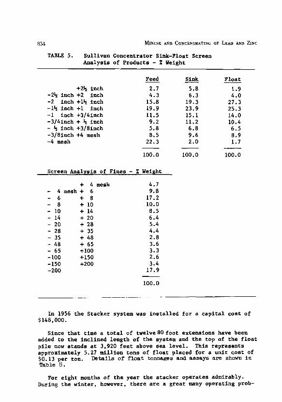
TABLE 5. Sullivan Concentrator Sink-Float Screen Analysis of Products - % Weight
+2% inch -2% inch +2 inch -2 inch +1+ inch -1% inch +1 inch -1 inch +3/4inch -3/4inch + + inch - 5 inch +3/8inch -3/8inch +4 mesh -4 mesh
Feed - 2.7 4.3
15.8 19.9 11.5 9.2 5.8 8.5
22.3
100.0
Sink - 5.8 6.3
19.3 23.9 15.1 11.2 6.8 9.6 2.0
100.0
Float
1.9 4.0
27.3 25.3 14.0 10.4 6.5 8.9 1.7
Screen Analysis of Fines - % Weight
+ 4 mesh - 4 mesh + 6 - 6 + 8 - 8 + 10 - 10 + 14 - 14 + 20 - 20 + 28 - 28 + 35 - 35 + 48 - 48 + 65 - 65 +lo0 - 100 +I50 - 150 +200 -200
In 1956 the Stacker system was in s t a l l ed f o r a c a p i t a l cos t of $148,000.
Since t h a t time a t o t a l of twelve80 foot extensions have been added t o the incl ined length of the system and the top of the f l o a t p i l e now stands a t 3,920 f e e t above sea leve l . This represents approximately 5.27 mil l ion tons of f l o a t placed fo r a un i t cos t of $0.13 per ton. D e t a i l s of float tonnages and assays a re shorn i n Table 8.
For e ight months of the year the s tacker operates admirably. During the winter, however, there a r e a great many operating prob-
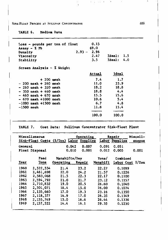
1 TABLE 6. Medium Data
Loss - pounds per ton of f l o a t 0.15 Assay - X Pb 69.0 Density 2.93 - 2.96 Viscosity 2.47 Ideal: 1.5 S t a b i l i t y 3.5 Ideal: 4.0
1 Screen Analysis - X Weight
+ 200 mesh - 200 mesh + 260 mesh - 260 mesh + 350 mesh - 350 mesh + 460 mesh - 460 mesh + 670 mesh - 670 mesh +I000 mesh -1000 mesh +I500 mesh -1500 mesh
Actual
7.4 11.0 18.2 18.8 15.5 10.6 6.7 11.8
100.0
Ideal
1.7 33.9 18.8 4.4 15.6 5.4 4.8 15.4
100.0
TABLE 7. Cost Data: Sullivan Concentrator Sink-Float Plant
Miscellaneous Operating Repair Miscell- Sink-Float Costs ($/Ton) Labor Supplies Labor Supplies aneous
General 0.042 0.007 0.091 0.051 Float Disposal 0.010 0.001 0.012 0.005 0.001
Year - 1960 1961 1962 1963 1964 1965 1966 1967 1968 1969
Feed Manshif ts/Day Tons Operating Repair -
2,522,554 21.4 23.2 2,461,698 22.0 24.2 2,583,068 21.5 22.3 2,594,792 21.0 21.7 2,710,832 19.0 20.5 2,301,071 18.4 15.0 2,135,660 17.0 19.3 2,118,377 14.9 17.0 2,155,749 15.0 16.6 2,157,522 14.4 16.1
Tons/ Manshif t
22.27 21.57 22.17 23.12 26.60 26.00 23.16 26.35 26.44 29.35
Combined Labor Cost $/Ton
0.1099 0.1226 0.1100 0.1157 0.1040 0.1074 0.1350 0.1349 0.1336 0.1230
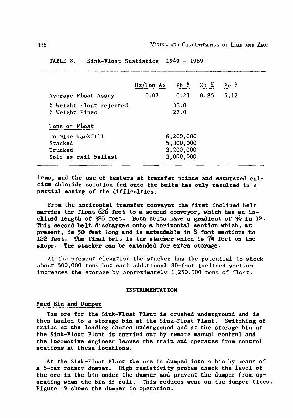
836 MINING AND CONCENTRATING OF LEAD AND ~ N C
TABLE 8. Sink-Float S t a t i s t i c s 1949 - 1969
Oz/Ton> E b A %% Fe% --
Average Float Assay 0.07 0.21 0.25 5.12
% Weight Float re jec ted % Weight Fines
Tons of F l 9 i
To Mine b a c k f i l l Stacked Trucked Sold a s r a i l b a l l a s t
l ens , and t h e use of hea te rs a t t r an s f e r po in t s and sa tura ted ca l - cium ch lor ide so lu t i on fed onto t h e b e l t s has only r e su l t ed i n a p a r t i a l easing of t h e d i f f i c u l t i e s .
From the hor izonta l t r an s f e r conveyor the f i r s t inc l ined b e l t carries the float 626 feet to a second conveyor, which has an in - c l i n sd leng th o f 326 feet. Both belts have a grad ien t o f 3* i n 12. This second belt discharges onto a hor izonta l sec t ion which, a t present , is 50 f e e t long snd is extendable i n 8 foo t sec t ions t o 122 feet. The f i n a l belt is t h e s t a cke r which is 74 f e e t on t h e s lope. The stacker can be extended for extra storage.
A t the present e leva t ion t he s tacker has the po t en t i a l t o s tock about 500,000 tons but each addi t iona l 80-foot inc l ined sec t ion increases the s to rage by approximately 1,250.000 tons of f l o a t .
INSTRUMENTATION
Feed Bin and Dumper
The ore f o r t he Sink-Float P lan t is crushed underground and i s then hauled t o a s to rage b in a t t h e Sink-Float Plant . Switching of t r a i n s a t the loading chutes underground and a t the s to rage b in a t t h e Sink-Float Plant is ca r r i ed ou t by remote manual con t ro l and t h e locomotive engineer leaves t he t r a i n and operates from cont ro l s t a t i o n s at these loca t ions .
A t t h e Sink-Float P lan t t h e o r e i s dumped i n t o a b i n by means of a 5-car r o t a ry dumper. High r e s i s t i v i t y probes check t he l e v e l of t h e o r e i n t he b in under t he dumper and prevent t h e dumper from op- e r a t i ng when t he b in i f f u l l . This reduces wear on t h e dumper tires. Figure 9 shows t he dumper i n operation.
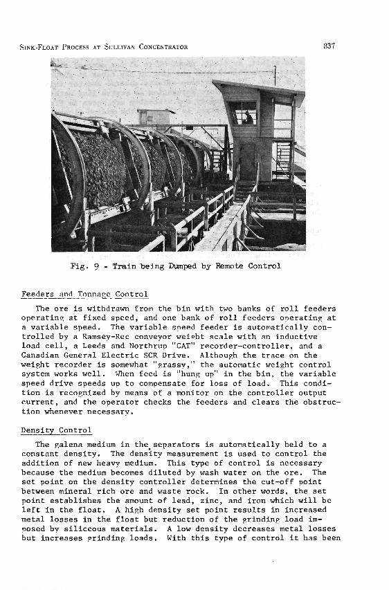
Fig. 9 - T r a i n be ing Dumped by Remote Control
Feeders and Tonnape Control
The o r e is withdrawn from the b i n wi th two banks of r o l l f eeders o p e r a t i n ? a t f ixed speed, and one bank of r o l l f eeders o n e r a t i n r a t a v a r i a b l e speed. The v a r i a b l e speed feeder is automat ical ly con- t r o l l e d by a Ramsey-Rec conveyor weioht s c a l e wi th an induc t ive load c e l l , a Leeds and N o r t h r u ~ "CAT" recorder -con t ro l l e r , and a Canadian General E l e c t r i c SCR Drive. Althouch the t r a c e on the weight recorder is somewhat " ~ r a s s y , " t h e automatic weight c o n t r o l system works we l l . When feed i s "hung up" i n t h e b in . t h e v a r i a b l e speed d r i v e speeds up t o compensate f o r l o s s of load. This condi- t i o n is r e c o ~ n i z e d by means of a manitor on the c o n t r o l l e r output c u r r e n t , and t h e opera to r checks the feeders and c l e a r s the obst ruc- t i o n whenever necessarv.
Density Control
The galena medium i n the , separa to r s is au tomat ica l ly held t o a constant dens i ty . The d e n s i t y measurement is used t o c o n t r o l t h e a d d i t i o n of new heavy medium. This type of c o n t r o l is necessary because t h e medium becomes d i l u t e d by wash water on t h e o r e . The s e t po in t on t h e dens i ty c o n t r o l l e r determines t h e cut-off po in t between mineral r i c h o r e and waste rock. I n o t h e r words, t h e s e t ' po in t e s t a b l i s h e s the amount of l ead , z inc , and i r o n which w i l l be l e f t i n t h e f l o a t . A high dens i ty s e t po in t r e s u l t s i n increased metal l o s s e s i n t h e f l o a t but r educ t ion of t h e g r i n d i n r load i m - posed by s i l i c e o u s mate r ia l s . A low d e n s i t y decreases metal l o s s e s but inc reases pr inding loads . With t h i s type of c o n t r o l i t has been
possible to reject, as float, about 30 to 35 per cent of the feed and maintain the combined lead and zinc in the float at about 0.4 per cent or less. Viscosity also affects control and for this rea- son, the ore is washed before separation to remove fine materials. The overall effects of density and viscosity are shown in figure 10. Automatic density control is shown in the medium flowsheet (fig. 7 ) .
The galena medium is held to a constant density by a Honeywell Electronic 18 three mode recorder-controller, a Nuclear Chicago density gauge, a Honeywell pneumatic operator and positioner, and a Clarkson B valve. The Clarkaon B valve is merely a pinch valve inside a pipe section and this type of valve appears to be the most satisfactory type to use in controlling slurry flows. The gamma ray density gauge ie mounted on a vertical pipe with an upflow of circulating medium. The radioactive source is mounted on one side of the pipe while the detector is mounted on the other.
Reagents
A small Mineral Separation flotation machine is used to clean up and recover medium. Control of reagents is by time modulation using Hagen per cent-of-cycle timers and solenoid valves. The timers thus provide remote manual control of reagents.
Sink Bin Tripper Controls
The sink is discharged into the bin by means of an automatically controlled travelling tripper which traverses the length of the bin. The various sections of the bin are equipped with resistivity probes to indicate high level and to supply signals to the tripper which searches out low sections of the bin. The east end of the bin nearest the rod mill holds priority and recalls the tripper to that section of the bin when feed is low.
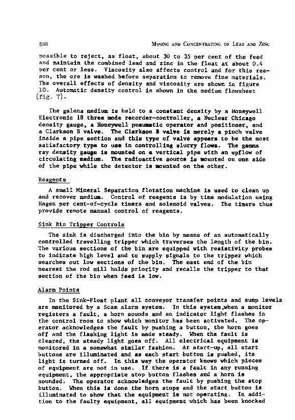
Alarm Points
In the Sink-Float plant all conveyor transfer points and sump levels are monitored by a Scam alarm system. In this system,when a monitor registers a fault, a horn sounds and an indicator light flashes in the control room to show which monitor has been activated. The op- erator acknowledges the fault by pushing a button, the horn goes off and the flashing light is made steady. When the fault is cleared, the steady light goes off. All electrical equipment is monitored in a somewhat similar fashion. At start-up, all start buttons are illuminated and as each start button is pushed, its light is turned off. In this way the operator knows which pieces of equipment are not in use. If there is a fault in any running equipment, the appropriate stop button flashes and a horn is sounded. The operator acknowledges the fault by pushing the stop button. When this is done the horn stops and the start button is illuminated to show that the equipment is not operating. In addi- tion to the faulty equipment, all equipment which has been knocked

L L . w 0 C,
2 1
VISCOSITY LlMl T ------- - - - -
I I I
CONTROL POINT
1 2 3 SPECIFIC GRAVITY OF ME01 UM
+ HIGHER GRINDING LOAD HIGHER FLOAT LOSSES -+
Wg. 10 - Curvea ehcning tbe Effect of I a w Speciflc h v i t y Ykteriale on Medium
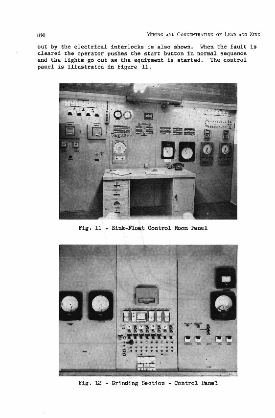
out by the electrical interlocks is also shown. When the fault is cleared the operator pushes the start button in normal sequence and the lights go out as the equipment is started. The control panel is illustrated in figure 11.
F'ig. 11 - Sink-Float Control Room Panel
Fig. 12 - Grinding Section - Control Panel

Remote Ind ica tors
Communication between t he Sink-Float p lan t and t h e Grinding sec- t i o n is provided by means of ind ica tor l i g h t s on t he c e n t r a l con- t r o l panel located near t he rod m i l l . The grinding operator is responsible f o r looking a f t e r the supply of heavy medium make-up which is f loa ted from the c e l l s shown i n f igure 13,
FYg. 13 - Coarse Lead Flo ta t ion
MAINTENANCE
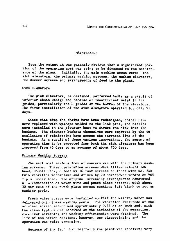
From the ou t s e t i t was pa ten t ly obvious t ha t a s i gn i f i c an t por- t i on of t he operat ing cos t was going t o be d i r ec t ed t o t he mainten- ance of the p lan t . I n i t i a l l y , the main problem a r ea s were: t he s ink e leva tors , the primary washing screens, the medium e leva tors , t he Hunaaer screens and arrangements of feed t o t he p lan t .
Sink Elevators
The s i nk e leva tors , a s designed, performed badly a s a r e s u l t of i n f e r i o r chain design and because of i n s u f f i c i e n t metal i n the guides, p a r t i c u l a r l y t he U-guides at the bottom of the e leva tors . The f i r s t i n a t a l l a t i o n of t he s i nk e l eva to r s operated f o r only 95 days.
Since t h a t time t h e chains have been redeoimed, c o t t e r p ins were replaced with warhers velded t o t he l i n k pins , and b a f f l e s were i n s t a l l e d i n t he e l eva to r boot t o d i r e c t t he s i nk i n t o t he buckets. The e l eva to r buckets themselves vere improved by the in- s t a l l a t i o n of re in forc ing bars across t h e s e r r a t ed l i p s of the buckets. A s a r e s u l t of these var ious innovations, t he amount of operat ing time t o be expected from both t he s i n k e leva tors has been imoroved from 95 days t o an average of about 250 days.
Primary Washin? Screens
The next most s e r i ous item of concern was with the primary wash- in? screens. These preparat ion screens were Allis-Chalmers low head, double deck, 6 foot by 16 foot screens equipped with No. 3,YD twin v ibra t iny mechanisms and dr iven by 20 horsepower motors a t 965 r.p.m. under load. The o r i ~ i n a l screening arrangements consis ted of a combination of woven wire and punch p l a t e screens, with about 50 per cent o f the punch p l a t e screen sec t ions l e f t blank t o a c t a s washinp pools.
Fresh water sprays were i n s t a l l e d so t ha t the washing water was del ivered onto these washinp pools. The v ibra t ion amplitude of the o r i v ina l screen set-up was approximately 0.44 of an inch and, with t h e clean tvpe of o r e received a t the beqinninv of the ooera t ion , exce l len t screening and washinp e f f i c i enc i e s were obtained. The l i f e of the screen s ec t i ons , however, was disappoint in? and t he operat ion was qu i t e emens ive .
Because of the f a c t t ha t i n i t i a l l y the p lan t was receiving very

c lean o r e i t was decided t o convert t h e p repara t ion sc reens t o s i n q l e deck u n i t s i n Sentember of 1950 and t h i s r e s u l t e d i n a s i p -
n i f i c a n t r educ t ion i n maintenance c o s t . Durinp t h i s per iod of op- e r a t i o n an a t temnt was made t o opera te with a s i n g l e v i b r a t o r in- s t ead o f t h e twin mechanism, bu t t h e amplitude dropped t o 0 . 2 5 of an inch and i t became d i f f i c u l t t o keep the screen proper lv ba l - anced. Because of t h i s , t h e a t t m p t t o onera te wi th one v i b r a t i n p u n i t was abandoned.
I n 1952 i n a d d i t i o n t o t h e need t o r e i n f o r c e t h e screen body, a chancre i n t h e o r e c h a r a c t e r i s t i c s took o l a c e and the feed t o the p l a n t became extremely h i ~ h i n c lay .
Because of t h e premature f a i l u r e of the sc reen frames and f o r b e t t e r wash in^ e f f i c i e n c y because of t h e c lay . i t was then decided t o r e v e r t back t o double deck sc reen inp with a screen body of much heav ie r cons t ruc t ion , and a l s o t o incorpora te a new stepped-deck des ien f o r e r e a t e r washinp e f f i c i e n c y . It was c a l c u l a t e d t h a t the weieht of t h e screen would be approximately two tons e r e a t e r than t h a t of t h e o r i e i n a l double deck u n i t and t h a t t h e amplitude of the sc reen would be reduced t o approximately 0 . 3 4 of an inch. This was expected t o be s u f f i c i e n t t o prevent blind in^ of t h e screening panels .
The new heavy dutv double deck sc reens were purchased from Allis-Chalmers and thev went i n t o opera t ion dur ine t h e e a r l y p a r t of 1953. A t t h i s s t a g e t h e sc reens were equioped wi th too deck havina 7 / 1 6 inch openinas and a bottom deck with 3 nun ooeninps. blind in^ of both t h e ton and bottom deck became a s e r i o u s oroblem from t h e o u t s e t and, a f t e r c o n s u l t a t i o n s wi th t h e manufacturers and a e r e a t dea l of emer imenta t ion i n t h e p l a n t , the sc reen a r r - aneement was es tab l i shed with punched p l a t e h a v i n ~ 314 inch round ho les wi th inch s t a c ~ e r e d c e n t e r s f o r t h e too deck ~ a n e l s and hav- i n g s t a i n l e s s s t e e l Ton-Can sc reen nanels wi th 0.146 inch by 1% inch s l o t ooeninqs f o r the bottom deck.
The averape amnlitude from s e v e r a l t e s t s taken a t t h i s time was 0 . 2 3 of an inch. This moved adequate t o prevent b l i n d i n e wi th t h e 314 inch round ho les on t h e top deck and the T 0 n - h ~ sc reens on t h e bottom deck.
I n s n i t e of t h e d e l i b e r a t e a t tempt t o r e i n f o r c e t h e sc reen , t h e s t e p cons t ruc t ion proved t o be inadequate f o r the job and f a t i e u e crackinp was observed a f t e r a r e l a t i v e l y s h o r t per iod of onerat ion. A t t h i s s t a e e the maintenance department constructed a comoletely new heavy duty screen which was of u n i t cons t ruc t ion , a l l welded, wi th a slop in^ deck, bu t wi th no chance i n t h e screen conf ieura t ion r e f e r r e d t o i n t h e previous oaragraph.
General ly speaking t h e r e have been r e l a t i v e l y few changes s i n c e the a l l welded, u n i t sc reen was adopted and, a p a r t from some ex- per imentat ion wi th l i n a t e x sc reens and proposed exper imentat ion wi th Skeca and Trelaborg sc reens , i t is n o t proposed, a t t h i s t ime, t o make any f u r t h e r modif ica t ions .
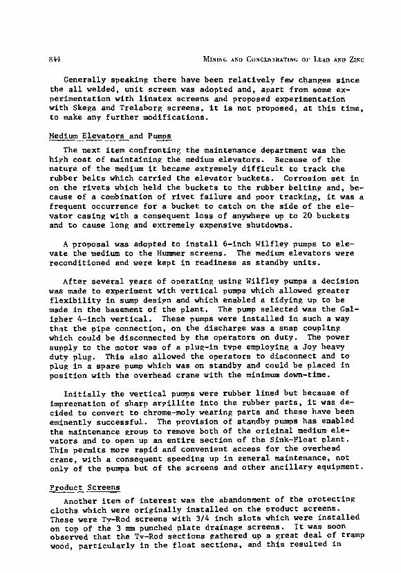
Medium Eleva to r s and Pumps
The next i tem conf ron t ing t h e maintenance department was t h e h iph c o s t of mainta ining t h e medium e l e v a t o r s . Because of the n a t u r e of t h e medium i t became extremely d i f f i c u l t t o t r a c k t h e rubber b e l t s which c a r r i e d t h e e l e v a t o r buckets . Corros ion s e t i n on t h e r i v e t s which he ld t h e buckets t o t h e rubber b e l t i n g and, be- cause of a combination of r i v e t f a i l u r e and poor t r a c k i n g , i t was a f requent occurrence f o r a bucket t o c a t c h on t h e s i d e of t h e e l e - v a t o r cas ing wi th a consequent l o s s o f anywhere up t o 20 buckets and t o cause long and extremely expensive shutdowns.
A proposal was adopted t o i n s t a l l 6-inch I J i l f l e y pumps t o e l e - v a t e t h e medium t o t h e Hunrmer sc reens . The medium e l e v a t o r s were recondi t ioned and were kept i n r ead iness a s s tandby u n i t s .
A f t e r s e v e r a l yea r s o f o p e r a t i n g us ing Wilf ley pumps a d e c i s i o n was made t o experiment wi th v e r t i c a l pumps which allowed g r e a t e r f l e x i b i l i t y i n sump des ipn and which enabled a t i d y i n g up t o be made i n t h e basement of t h e p l a n t . The pump s e l e c t e d was t h e Gal- i g h e r 4-inch v e r t i c a l . These pumps were i n s t a l l e d i n such a way t h a t t h e p i p e connect ion, on the discharge was a snap coupling which could b e disconnected by t h e o p e r a t o r s on duty . The power supply t o t h e motor was o f a plug-in type employinp a Joy heavy duty plug. This a l s o allowed the o p e r a t o r s t o d isconnect and t o plug i n a s p a r e pump which was on standby and could be placed i n p o s i t i o n wi th t h e overhead c rane wi th t h e minimum down-time.
I n i t i a l l y t h e v e r t i c a l pumps were rubber l i n e d bu t because of impreenation of sha rp a r p i l l i t e i n t o t h e rubber p a r t s , i t was de- c ided t o conver t t o chrome-moly wearing p a r t s and t h e s e have been eminently success fu l . The p rov i s ion of standby pumps has enabled t h e maintenance grour, t o remove both of the o r i g i n a l medium e l e - v a t o r s and t o open up an e n t i r e s e c t i o n of t h e Sink-Float p l a n t . Th i s permits more r a p i d and convenient access f o r t h e overhead c rane , wi th a consequent speeding up i n general maintenance, n o t only of the pumps but of t h e s c r e e n s and o t h e r a n c i l l a r y equipment.
Product Screens
Another i tem of i n t e r e s t was t h e abandonment of t h e v r o t e c t i n g c l o t h s which were o r i g i n a l l y i n s t a l l e d on t h e product sc reens . These were Tv-Rod sc reens wi th 3/4 inch s l o t s which were i n s t a l l e d on top of t h e 3 mm punched p l a t e dra inage sc reens . I t was soon observed t h a t the Tv-Rod s e c t i o n s gathered up a g r e a t d e a l of tramp wood, p a r t i c u l a r l y i n t h e f l o a t s e c t i o n s , and t h i s r e s u l t e d i n

ser ious bl inding problems which shut down the plant . Apart from a pro tec t ive c lo th on the very f i r s t sec t ion of both t he sink and the f l o a t product screens, a l l protect ing c lo ths have been removed and the bl inding no longer cons t i t u t e s a problem.
Reference was made e a r l i e r t o t he problems associated with main- tenance on the Hummer screens. This i s probably a na tura l function of t h i s type of v ibfa t ing screen. Or ig ina l ly t he screen c lo th s e l - ected was obviously f a r too f i ne a t 100 mesh and the operators be- came gradually aware t ha t they could accept a coarser mesh, and the current Hummer screens, which screen out t he degradation product from the c i r cu l a t i ng medium, a re 20 mesh screens with a backing c lo th f o r support.
Feeders and Conveyors
The o r ig ina l feed arrangements from the Sink-Float bin ca l led f o r a l l nine r o l l feeders t o be connected t o a common shaf t . This caused considerable d i s loca t ion of the operation, the breakdown of a s ing le feeder shut the e n t i r e feed off the plant and i t was not u n t i l t he problem had been r e c t i f i e d t ha t feed could be restored again.
The s ing le l i n e sha f t was very soon converted i n to th ree d i s - t i n c t l y separate u n i t s each comprising three r o l l feeders. Since instrumentation has been introduced i n t o the p lan t the center bank of feeders has been converted from f ixed speed t o an SCR var iab le speed drive. A second group of th ree i s i n process of conversion t o var iab le speed.
One item of maintenance "know-how" which contributed t o a s ig- n i f i c an t increase i n the a v a i l a b i l i t y of the p lan t was the i n t ro - duction of a shear coupling on the sha f t of the individual feeders so t h a t , i n the case of any obstruct ion i n the discharge point of the bin, the feeder merely sheared the pins. There was no s i g n i f i - cant o r major damage done t o the shaf t ing o r the d r ive , and the op- e r a to r was ab le t o replace pins whenever he inspected the feeding arrangements.
There were the normal problems associated with conveying which a r e common t o a l l plants . A campaign was conducted t o clean up the plant by the introduct ion of more e f f i c i e n t scraping and one s ign i - f i c an t improvement t o the b e l t scraping was t h e development of a ro ta ry , lawn-mower-type, rubber-bladed scraper which was dr iven by a small high speed motor.
The feed arrangements t o the individual separators were i n i t i a l l y a s i ng l e c ross -be l t with a plough scraper t o provide feed t o the

most northerly o f the two units . This was unquestionably one o f the worst set-ups which has ever been designed.
The present arrangement has a twin-chute discharge with air op- erated cut-off gates to give remote control to the operators. When the plant i s running normally the incline conveyor bringing the feed up from the bin discharges into t h i s two-way sp l i t t e r chute and one half o f the feed goes directly t o Number 1 un i t , into the washing pool. The other half o f the feed i s discharged onto a cross-con- veyor and i s fed over to the second or most southerly uni t . The operation thus far has been satisfactory with few o f the attendant housekeeping problems exphrienced with the original feed arrange- ment.
Fines - Transportation t o Grinding Circuit
Fines pumping was quite a problem with the rubber lined pumps specified i n the original layout o f the plant. Once again the very abrasive arg i l l i t e s impregnated the rubber, and l i f e o f the runners and casings on these pumps was measured i n hours rather than days. Changes were made to use metal wearing parts and, within the l imi t s o f normal expectation, the pumping o f f ines over t o the c l a s s i f i - cation and grinding circuit has been relatively trouble free.
I t i s unfortunate that the same thing cannot be said for the pipe l ines which carry the minus 1 / 4 inch material t o the grinding sec- tion. After considerable experimentation with various types o f metal pipe it was decided to go to a thick wall rubber reinforced piping for t h i s product. Despite the fact that the cost i s f i v e and a half times that o f black iron, the performance has been im- proved to the point where it i s quite practical and economical to use expensive rubber pipe.
Ways and means o f improving maintenance performance are being sought continuously and a study i s currently under way to investi- gate the possibil i ty o f converting the operation o f the plant to ferrosilicon medium with a view to eliminating some o f the higher cost maintenance items. This study i s s t r i c t l y o f a preliminary nature, and it i s quite possible that the separators w i l l not be replaced and that the increased cost o f ferrosilicon w i l l more than o f f s e t any savings i n galena medium preparation.
Typical maintenance data are given i n Table 9 .

TABLE 9. Maintenance Items - Frequency and Cost
Item - Sink Elevators Clean-up Elevator Product Screens Hummer Screene Separator6 Medium Circui t Bins and Feeders Conveyors and Stacker pumps Instruments Building Maintenance Planning Supervision Miscellaneous
TOTAL
In terva l
Yearly Quarterly Weekly Weekly Variable Variable Weekly Weekly Variable Weekly Variable Daily Daily Variable
Manshif ts/ Year
337 165 255 2 10 6 7
3 35 420 675 500 45
210 105 420 136
3,880
Total Maintenance
Cost $/Ton
0.0135 0.0058 0.0155 0.0068 0.0025 0.0117 0.0169 0.0254 0.0169 0.0016 0.0084 0.0003 0.0090 0.0247
CONCLUSION
Table 10 is a l i s t of some of t he p lan ts which have used t h e Sink-Float process a s a pre-concentration s tage i n the recovery of lead.-zinc. The majority of t he mines l i s t e d a r e medium t o small tonnage un i t s , some a r e i n remote geographic a reas , which could i nd i ca t e water and/or supply problems, but they a l l operate (or d id operate) a gravi ty separat ion p lan t , using heavy medium, and they did so with a grea t measure of success.
I t i s conceivable with the advances which have been made i n crushing, grinding and f l o t a t i o n equipment during the past 20 odd years t ha t some of the la rger un i t s l i s t edmigh t have e lec ted t o opt out of the Sink-Float f i e l d , had the decision t o bui ld been made i n 1969 inetead of 1939. Autogenous grinding, l a rge r crushers, automation and instrumentation, bigger and b e t t e r pumps and the constant improvement of f l o t a t i o n equipment, with associated re- ductions i n c a p i t a l and operating cos t s per ton, have made the process of se lec t ion more d i f f i c u l t .
Tax s t ruc tu re is becoming increasingly important i n the .dec is ion making process, pa r t i cu l a r ly with respect t o big tonnage proposi- t ions which requi re r e l a t i v e l y l a rge cap i t a l i za t i on . The a r t of mineral engineering can go only so f a r i n the economical j u s t i f i -

TABLE 10. Heavy Media Plants
Lead Ores
Name - Linton Mines Halkyn Mines Glebe Mine Zellid ja T r i S ta te Mining Penarroya Raibl Mine nines D'Amronzo St. Joseph Lead Co. pyfrebrune Mine %unt I sa Mines Ltd. Ge Aramayo S. A. S t . Joseph Lead Co.
Locat ion
Bonita, Mon. Halkyn, U.K. Derbyshire, U. K. Fr. Morocco U. S. A. I t a l y I t a l y Bonneterre , Mo . France Queensland, Austral ia Animas , Bolivia Haydon Creek
Lead-Zinc Ores
American Zinc Co. Mascot, Tennessee Eagle Pitcher M 6 S Cardin, Oklahoma Bunker H i l l M 6 S Kellogg, Idaho Viel le Montagne Sweden Mesloula Algeria Cominco Ltd. Umberley, B. C. Sindicated Minero Rio Alpamarca, Peru
Pallanca Zambian Broken H i l l Zambia Mitsubishi Metal Min.Co. Hosokura, Japan Toho Zinc Co. Taishu, Japan
Feed Rate %?!? Tons/Hour
7' Mobil-Mill 35 B C H 25 H C H 10 18' Cone 50 H C H 4 0 H C H 65 H C H 40 H C H 85 Wemco Drum 10 Wemco Drum 2 0 Wemco Cone 25 H L H 85
H.M.S. Cone 165 H.M.S. Cone 4 00 H 6 H 135 H C H 45 7' Mobil-Mill 40 H C H 500 H.M.S. 20
Wemc0 Drum 90 Swirl Cyclone 30
Feed Size -
3"-6 mm 3-30 mm 3-25 m -
Star t ing Date S .G.

TABLE 10. Heavy Media P l a n t s (contd)
Name - Hokuriku Kozan O.C. Corp. Blaymard L'Union Miniere Pyrenes Sachtleben-Meggen O.C. Corp. Geotecnica S.A.C. Montevecchio Co. Montevecchio Co. Campo P i sa jo Penarroya-Aouli Mine Penarroya San Giovanni Penarroya Cen ten i l lo Penarroya Salafossa I Penarroya Sa la fossa I1 Hecla Mining Co.
Location BS Ogoya, Japan Akins Lezere, France Wemco Drum Sent ien, France Wemco Drum Germany Wemco Drum Mezica, Yugoslavia Wemco Drum Buenes Ai res , Argent ine Wemco Drum Levante, Sa rd in ia . H 6 H Ponente, Sa rd in ia H 6 H Sard in ia H 6 H Midelt , Morocco H i i H Sa rd in ia H 6 H Spain H 6 H I t a l y Wemco Drum I t a l y Wemco Drum Idaho H 6 H
Zinc Ores
S t . Joseph Lead Co. Josephtown Smelter Wemco Drum Penarroya Bugguru Sard in ia H 6 H
Copper-Lead Ore
Uruwira Minerals Ltd. Mpanda, Tanzania H 6 H Uruwira Minerals Ltd. Mpanda, Tanzania Wemco Drum
z T.
Feed Rate Feed S t a r t i n g 7 0
Tons/Hour Size Date S. G. 1
15 +5 mm - 2.43 2
- - 2 2 25-2 mm S 25 25-8 mm - * - 40 70-2 rn - - 4
88 2-50 nun - c - V1
F 12 I+"-7 m - - - P
35 3-25 IDIQ - 2.70 z 2 35 3-25 UUII - 2.70 10 3-25 rrrm - 2.70 6 4 5 6-40 mm 1952 2.65
4 n
20 - 1951 - z 1 w
4 5 - 1958 2-
30 50-4 mm 1960 2.74 0 w
100 50-4 1965 2.74 125 - - -
cation of any particular mining venture. Government must also bear some responsibility.
Acknowledgments
The author wishes to acknowledge the generous assistance given to him by the following persons.
Mr. Paul Raffinot - Societe Miniere et Metallurgique de Penarr- oya.
Mr. H. A. Steave - Placer Development Ltd. Mr. H. Hartjens - American Cyanmind Co. Mr. H. T. Brown - Simon-Carves Ltd. Mr. J. G. Eby - Wemco (Canada) Ltd. The Staff - Cominco Ltd., Sullivan Concentrator.
Permission by Cominco Ltd. to publish this paper is also gratefully acknowledged.
REFERENCES
(1) Grove, D. B., Brackin, R. B. and Polhemus, J. H., "Compara- tive Results With Galena and Ferrosilicon at Mascot," Mining Engineering, August 1951, pp. 691 - 698.
(2) Lund, R. E., Welch, G. E., Ferrighetto, J. and Hoffacker, B. E., "An Unusual Application of Heavy Media Separation," Mining Engineering, Dec. 1968,(Vol. 20, No. 12.)
(3) Bellanita, G. and Antoniolli, R., "Jig Concentrate and Flotation Concentrate as Heavy Media at the Two Huntington- Huberlein Sink-Float Plants of the Montevecchio Co.," International Mineral Dressing Congress, Stockholm, 1957.
(4) Stockett, N. A., "Developments in Milling Practice in SouthaetMissouri," Mining Congress Journal, April 1953, pp. 84 - 87.
(5) Stiles, E. M., Nagle, E. H. and Knighton, G. J., "Recent Improvements at the Sullivan Operations of the Coneoli- dated Mining and Smelting Company of Canada, ~imited," Trans. CIMM, Vol. 53, 1950, pp. 152 - 165.
(6) Staff, "How New Unite, New Uses Widen Scope of Sink-Float," E W Vol. 152, No. 7, July 1951, pp. 130 - 133. -
(7) Raffinot, P., Private Communication, 1969.
(8) Volk, F. W., "Ergebnisse Der umstellung Von Bleiglanz Auf Ferrosilizium Ale Beschweretoff In der Schwimm Sink-Anlage Der Aufbereitung Ramsbeck. " Erzmetall Bd 18, 1965.
(9) Staff, "Why an Atomized Ferrosilicon Proves Superior for Heavy Media Plants," World Minin~, March 1960. pp. 32 - 35.
(10) H. T. Brown, Simon-Carvea Limited, Private Communication 1969.
(11) Bloomer, P. T., "Pillar Extraction at the Sullivan Mine," Bulletin CIMM, No. 429, Jan. 1948, pp. 2 - 13.
(12) Banks, H. R., "Sink-Float at the Sullivan Concentrator," Mining Congress Journal, July 1950, pp. 29 - 31.