Embed Size (px)
Citation preview
Computers & Fluids 114 (2015) 110–120
Contents lists available at ScienceDirect
Computers & Fluids
journal homepage: www.elsevier .com/locate /compfluid
Numerical study on dynamic sorting of a compliant capsulewith a thin shell
http://dx.doi.org/10.1016/j.compfluid.2015.02.0210045-7930/� 2015 Elsevier Ltd. All rights reserved.
⇑ Corresponding author.
Huilin Ye, Haibo Huang ⇑, Xi-yun LuDept. of Modern Mechanics, Univ. of Sci. and Tech. of China, Hefei 230026, China
a r t i c l e i n f o
Article history:Received 4 December 2014Received in revised form 10 February 2015Accepted 28 February 2015Available online 9 March 2015
Keywords:LBMLSMShear flowDeformable particleNarrow channelMulti-particles
a b s t r a c t
Sorting compliant capsules is an interesting research topic. In this paper, a simple bifurcated micro-channel is used to sort the particles with different rigidities. The behavior of a compliant particle insidethe channel is investigated numerically. The fluid flow and the particle’s deformation are solved byLattice Boltzmann Method (LBM) and Lattice Spring Model (LSM), respectively. The fluid and solid solversare coupled through interpolated bounce-back scheme. Two benchmark problems are used to validateour method. One is the motion of a compliant capsule in a channel and the other is the deformation ofa capsule inside a simple shear flow. The results are quantitatively consistent with those in literature.By taking advantage of the rotating of capsules in shear flow, a simple distinguished bifurcated micro-channel is proposed to sort capsules with different rigidities. In this micro-channel, the initial offsetand shear stress induce the rotating and lateral migration of the capsule and flux ratio is determinedby the outlet pressures. The competition between the effect of initial offset and flux ratio contributesto the sorting mechanism. Compared to other micro-channels with different geometrical models, presentone is more convenient and may be more efficient to screen the microcapsule we want.
� 2015 Elsevier Ltd. All rights reserved.
1. Introduction
In recent years, researchers are very interested in the deforma-tion and motion behavior of a capsule enclosed with elastic mem-brane. A possible reason is that behavior of a capsule immersed influid is similar to that of a Red Blood Cell (RBC) suspended inplasma. As we know, the RBC plays important role in Oxygen trans-fer. The RBC is enclosed with lipid bilayer, which would protect theentity of the cell and afford the ability to deform. The RBC sus-pended in blood on one hand is driven to flow with the blood, onthe other hand is deforming under the effect of the fluid enclosingit. Hence, understanding the motion and deformation behavior ofthe RBC is important. In blood diseases like cerebral malaria andsickle cell anemia, the rigidity of RBC would be affected much[1]. When the RBC goes through the constricted capillary tube, itmay be unable to deform enough and in a certain condition, itmay be destroyed by a little stimulant such as some impurity con-tained in blood. For the application of capsules, artificial capsulesare often used in the pharmaceutical, cosmetics, and food indus-tries. They could regulate the release of active substances and fla-vors. Because of the small size and fragility, measuring themechanical properties of the membrane is very difficult.
Research in membrane hydrodynamics has achieved greatsuccess. It leads to numerous membrane constitutive laws. Thesimplest law is Hooke’s law restricted to small deformations.Another is Mooney–Rivlin (MR) law which assumed the membraneis a very thin sheet [2]. In order to model the large deformationsof RBC, Skalak et al. [3] proposed the Skalak (SK) Law. Sometheoretical studies have been carried out. Barthes-Biesel [4] andBarthes-Biesel and Rallison [5] applied a regular perturbation toanalyze cases where the deviation from spherical shape of thecapsule is small or large. Barthes-Biesel et al. [6] also comparedthe effect of constitutive laws for two dimensional (2D)membranes. They found that after a continuous elongation, acapsule with a MR membrane bursts, while a capsule with a SKmembrane would reach a steady state.
However, deformation of a RBC depends on not only the elasticof the membrane, but also the flow of fluid surrounding the RBC.The flows in complex geometry are difficult to be analyzed theo-retically. To study the deformation, usually experimental andnumerical methods are adopted. To investigate the deformationof a capsule in a simple shear flow, Chang and Olbricht [7] andWalter et al. [8] designed artificial capsules composed of differentmaterial. However, usually it is difficult to change the rigidity ofthe capsule in experiments. With the development of numericalmethods and computers, more researchers carried out relevantnumerical studies [9–17].
H. Ye et al. / Computers & Fluids 114 (2015) 110–120 111
Many numerical methods have been developed to solve boththe deformation of the capsule and fluid flow. For example,Woolfenden and Blyth [18] used boundary element method tosolve both the solid and fluid parts. Immersed-boundary method(IBM) is another simple but effective scheme to solve the flowproblem. The IBM is introduced by Peskin [19], and developed byFeng et al. [20], which is usually used to simulate the movingboundary problem. In the scheme, the deformation of capsuleand fluid flow are solved separately and the IBM is used to couplethe solutions. For example, MacMeccan et al. [21] and Sui et al. [11]applied the finite element analysis (FEA) and Lattice BoltzmannMethod (LBM) to solve the dynamics of the membrane and fluidflow, respectively. The IBM is adopted to couple the FEA andLBM. This method is able to simulate large numbers of capsulessuspended in fluid efficiently [12]. Sui et al. [9,10] identified vari-ous types of motion for a capsule freely suspended in simple shearflow. For an initially spherical capsule, it would exhibit a steady‘‘tank-treading’’ motion, wherein the capsule deforms into a sta-tionary shape with a finite inclination with the flow directionand the membrane would rotate around the interior liquid. Kellerand Skalak [22] analyzed the motion of a viscous ellipsoid andinvestigated the effect of viscosity ratio of the inner and outerfluids. They found the critical viscosity ratio for a capsule translat-ing from tank-treading motion to tumbling motion. Abkarian et al.[23] and Skotheim and Secomb [24] found that lowering the shearrate of the external flow could trigger the transition from succes-sive swinging mode to the pure tumbling mode. Kessler et al.[25] concluded a full phase diagram for varying shear rate and vis-cosity ratio.
For studies of capsules sorting, Alexeev et al. [26–28] came upwith an idea about capsules that are driven by a shear flow goingthrough compliant substrates or corrugated surfaces. The motionof capsules can be controlled through changing rigidity of the sub-strates or corrugated structure. Zhu et al. [29] designed a con-stricted pillar geometrical model to regulate the motion ofcapsule because the velocity of the capsule depends on the rigidityof the capsule. However, the above sorting methods are not easilyand efficiently applied in engineering. Now, more and moreresearchers try to design different mechanism to sort capsules withdifferent rigidity.
Here, taking advantage of ‘‘tank treading motion’’, we designeda simple bifurcated micro-channel to sort capsules with differentrigidities. Through setting different pressures on the outlet bound-aries of the device, we can control which sub-channel the capsuleswill enter into. In the literature, there are some studies on capsules’behavior near the bifurcation. Woolfenden and Blyth [18] con-ducted a two-dimensional elastic fluid-filled capsule through achannel with a side branch. The deformation experienced by thecapsule near the junction of main channel and side branch is foundto depend strongly on the branch angle, and the path selection of acell at a branch junction can depend crucially on the capsuledeformability [18]. Hyakutake et al. [30] and Barber et al. [31] used2D bifurcation flow to investigate the blood cell behavior at micro-vascular bifurcations. They found the fractional particle flux to adaughter branch is almost similar to the fractional bulk flow tothe same branch in high hematocrit. However, in low hematocrit,the fractional particle flux against the fractional bulk flowincreases. Hence, in previous relevant studies, no one focused onsorting capsules using simple bifurcated micro-channel.
To evaluate the performance of the device we designed, we takea numerical study on the sorting mechanism. Our numericalmethod is based on that of Alexeev et al. [26]. Capsule is modeledas a fluid-filled elastic shell. The Lattice Spring Model (LSM) is usedto solve the deformation of the shell [32–35]. This model is able tosimulate the solid material constructed by isotropic homogeneouselastic medium [32]. In the model, discrete solid nodes are
connected with linear springs. For the fluid flow, the LBM is used,which is an efficient solver for Navier–Stokes equations [36–38].The interpolated bounce-back scheme is used to couple the fluidflow and deformation of the capsules. However, Omori et al. [14]has used the numerical test of tension-strain relations and the iso-tropic tension-area dilation relations for large deformation todemonstrate that the cross mesh type we used in our paperexhibits a strain-hardening behavior and strain-softening behav-ior,respectively. So we set the capsule’s deformation relativelylow ðCa < 0:2Þ in order to model the biological cell membraneswhich is local area incompressibility more closely.
In this paper, first the numerical methods about LBM and LSMare introduced briefly. Then the numerical method is validatedby two benchmark problems. One is the motion of a compliant cap-sule in a channel and the other is the deformation of a capsuleinside a simple shear flow. Finally, sorting mechanism of capsuleswith different rigidity through the bifurcated channel is explored.
2. Method
2.1. Lattice Boltzmann method
In our study, the fluid flow is solved using LBM. In the LBM, theBhatnagar–Gross–Krook (BGK) approximation for the collisionterm is adopted [36]. In the lattice BGK method, a distributionfunction f iðx; tÞ is introduced to implicitly represent all relevantproperties of the fluid. This distribution function satisfies the fol-lowing lattice Boltzmann equation [36]:
f iðxþ eiDt; t þ DtÞ ¼ f iðx; tÞ �1sðf iðx; tÞ � f eq
i ðx; tÞÞ; ð1Þ
where f iðx; tÞ is the density distribution function in the discretevelocity ei direction. f iðx; tÞ is functions of position x and time t. sis a non-dimensional relaxation time which is related to the kine-matic viscosity by m ¼ c2
s ðs� 0:5ÞDt. Usually in the LBM code, Eq.(1) is decomposed into two steps. One is the streaming step:
f iðxþ eiDt; t þ DtÞ ¼ fþi ðx; tÞ; ð2Þ
the other is the collision step:
fþi ðx; tÞ ¼ f iðx; tÞ �1sðf iðx; tÞ � f eq
i ðx; tÞÞ: ð3Þ
The equilibrium distribution function f eqi ðx; tÞ can be calculated
as [36]
f eqi ðx; tÞ ¼ wiq 1þ ei � u
c2sþ ðei � uÞ2
2c4s� ðuÞ
2
2c2s
" #: ð4Þ
In Eqs. (1) and (4), for the two-dimensional nine-velocity(D2Q9) model, eis are given by [36]
½e0;e1;e2;e3;e4;e5;e6;e7;e8� ¼ c �0 1 0 �1 0 1 �1 �1 10 0 1 0 �1 1 1 �1 �1
� �:
In Eq. (4) the weighting coefficients wi ¼ 4=9, (i = 0), wi ¼ 1=9,(i = 1, 2, 3, 4), wi ¼ 1=36, (i = 5, 6, 7, 8). The lattice sound speed inthe LBM [36] is cs ¼ cffiffi
3p for the D2Q9 model, where c ¼ Dx
Dt is the ratio
of lattice spacing Dx and time step Dt. Here, we define 1 lattice unit(Dx) as 1 lu, 1 time step (Dt) as 1 ts, and 1 mass unit as 1 mu.
In Eq. (4), q is the density of the fluid, which can be obtainedfrom the zeroth order moment of f i [36],
q ¼X
i
f i; ð5Þ
and q0 is used to denote the average density of the fluid. The fluidvelocity can be calculated through the first order moment of f i [36],
112 H. Ye et al. / Computers & Fluids 114 (2015) 110–120
u ¼ 1qX
i
f iei: ð6Þ
Macroscopically, the LBM recovers the Navier–Stokes equations.
2.2. Lattice spring model
The deformation of an elastic capsule is solved by the latticespring model [26]. In the model, the regularly spaced mass pointand nodes are connected by harmonic springs. The lattice springnodes are described in a Lagrange coordinate. The position of thenode i in the Euler coordinates (fixed in space) is ri, which maychange with time. The elastic energy on node ri is [26,33]
EðriÞ ¼12
Xj
kj rij � reqij
� �2; ð7Þ
where rij and kj are the length and the spring constant of the springconnecting ri and rj, respectively. rij and req
ij are the distancebetween ri and rj, and its equilibrium length, respectively. Hencethe summation is over all the springs connected with node ri. Thisresults in spring forces acting on node ri [26]
FsðriÞ ¼X
j
kj
rij � reqij
rij
!rij: ð8Þ
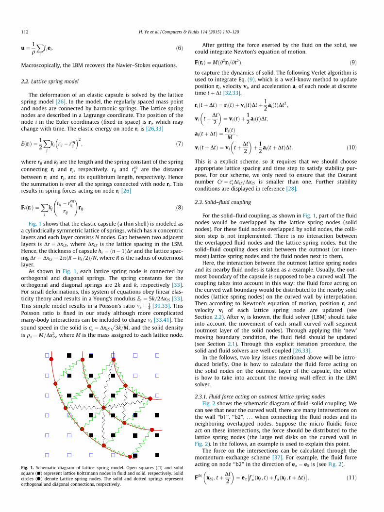
Fig. 1 shows that the elastic capsule (a thin shell) is modeled asa cylindrically symmetric lattice of springs, which has n concentriclayers and each layer consists N nodes. Gap between two adjacentlayers is Dr ¼ DxLS, where DxLS is the lattice spacing in the LSM.Hence, the thickness of capsule hs ¼ ðn� 1ÞDr and the lattice spac-ing Dr ¼ DxLs ¼ 2pðR� hs=2Þ=N, where R is the radius of outermostlayer.
As shown in Fig. 1, each lattice spring node is connected byorthogonal and diagonal springs. The spring constants for theorthogonal and diagonal springs are 2k and k, respectively [33].For small deformations, this system of equations obey linear elas-ticity theory and results in a Young’s modulus Es ¼ 5k=2DxLS [33].This simple model results in a Poisson’s ratio ms ¼ 1
4 [39,33]. ThisPoisson ratio is fixed in our study although more complicatedmany-body interactions can be included to change ms [33,41]. Thesound speed in the solid is c0s ¼ DxLS
ffiffiffiffiffiffiffiffiffiffiffiffiffi3k=M
p, and the solid density
is qs ¼ M=Dx2LS, where M is the mass assigned to each lattice node.
Fig. 1. Schematic diagram of lattice spring model. Open squares (�) and solidsquare (j) represent lattice Boltzmann nodes in fluid and solid, respectively. Solidcircles (�) denote Lattice spring nodes. The solid and dotted springs representorthogonal and diagonal connections, respectively.
After getting the force exerted by the fluid on the solid, wecould integrate Newton’s equation of motion,
FðriÞ ¼ Mð@2ri=@t2Þ; ð9Þ
to capture the dynamics of solid. The following Verlet algorithm isused to integrate Eq. (9), which is a well-know method to updateposition ri, velocity vi, and acceleration ai of each node at discretetime t þ Dt [32,33].
riðt þ DtÞ ¼ riðtÞ þ viðtÞDt þ 12
aiðtÞDt2;
vi t þ Dt2
� �¼ viðtÞ þ
12
aiðtÞDt;
aiðt þ DtÞ ¼ FiðtÞM
;
viðt þ DtÞ ¼ vi t þ Dt2
� �þ 1
2aiðt þ DtÞDt: ð10Þ
This is a explicit scheme, so it requires that we should chooseappropriate lattice spacing and time step to satisfy stability pur-pose. For our scheme, we only need to ensure that the Courantnumber Cr ¼ c0sDtLS=DxLS is smaller than one. Further stabilityconditions are displayed in reference [28].
2.3. Solid–fluid coupling
For the solid–fluid coupling, as shown in Fig. 1, part of the fluidnodes would be overlapped by the lattice spring nodes (solidnodes). For these fluid nodes overlapped by solid nodes, the colli-sion step is not implemented. There is no interaction betweenthe overlapped fluid nodes and the lattice spring nodes. But thesolid–fluid coupling does exist between the outmost (or inner-most) lattice spring nodes and the fluid nodes next to them.
Here, the interaction between the outmost lattice spring nodesand its nearby fluid nodes is taken as a example. Usually, the out-most boundary of the capsule is supposed to be a curved wall. Thecoupling takes into account in this way: the fluid force acting onthe curved wall boundary would be distributed to the nearby solidnodes (lattice spring nodes) on the curved wall by interpolation.Then according to Newton’s equation of motion, position ri andvelocity vi of each lattice spring node are updated (seeSection 2.2). After vi is known, the fluid solver (LBM) should takeinto account the movement of each small curved wall segment(outmost layer of the solid nodes). Through applying this ‘new’moving boundary condition, the fluid field should be updated(see Section 2.1). Through this explicit iteration procedure, thesolid and fluid solvers are well coupled [26,33].
In the follows, two key issues mentioned above will be intro-duced briefly. One is how to calculate the fluid force acting onthe solid nodes on the outmost layer of the capsule, the otheris how to take into account the moving wall effect in the LBMsolver.
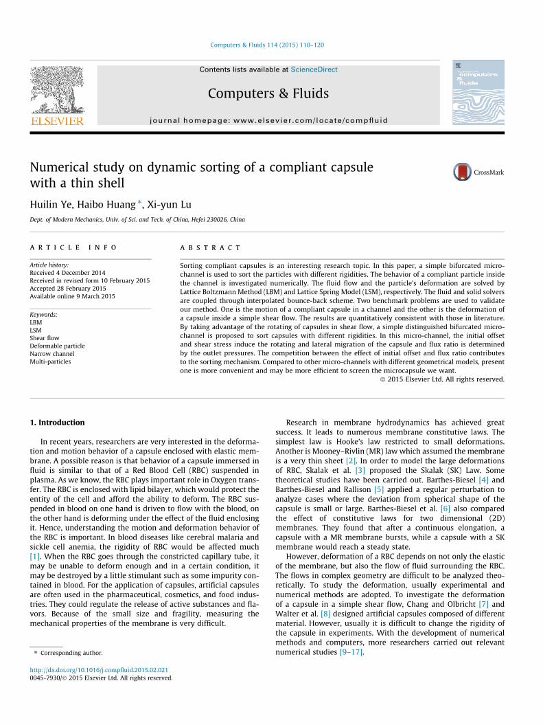
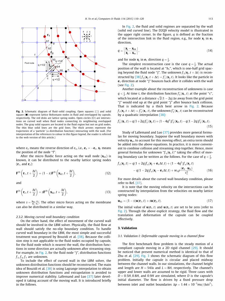
2.3.1. Fluid force acting on outmost lattice spring nodesFig. 2 shows the schematic diagram of fluid–solid coupling. We
can see that near the curved wall, there are many intersections onthe wall ‘‘b1’’, ‘‘b2’’, . . . when connecting the fluid nodes and itsneighboring overlapped nodes. Suppose the micro fluidic forceact on these intersections, the force should be distributed to thelattice spring nodes (the large red disks on the curved wall inFig. 2). In the follows, an example is used to explain this point.
The force on the intersections can be calculated through themomentum exchange scheme [37]. For example, the fluid forceacting on node ‘‘b2’’ in the direction of ea ¼ e5 is (see Fig. 2).
FðbÞ xb2; t þDt2
� �¼ ea fþa ðxf ; tÞ þ f �aðxf ; t þ DtÞ
; ð11Þ
q =1/2
Fluid node
j
e
c
d
q <1/2
2 5
4
3 1
87
6
a b4q >1/2
b5
b3
r
r1
2f
gb1
b2
m
n
Fig. 2. Schematic diagram of fluid–solid coupling. Open squares (�) and solidsquare (j) represent lattice Boltzmann nodes in fluid and overlapped by capsule,respectively. The red disks are lattice spring nodes. Open circles (�) are intersec-tions on curved wall when fluid nodes connecting its neighboring overlappednodes. The gray solid squares are located in the fluid region but not on grid nodes.The thin blue solid lines are the grid lines. The thick arrows represent thetrajectories of a ‘particle’ (a distribution function) interacting with the wall. (Forinterpretation of the references to colour in this figure legend, the reader is referredto the web version of this article.)
H. Ye et al. / Computers & Fluids 114 (2015) 110–120 113
where e�a means the reverse direction of ea, i.e., e�a ¼ �ea. xf meansthe position of the node ‘‘f’’.
After the micro fluidic force acting on the wall node (xb2) isknown, it can be distributed to the nearby lattice spring nodes(r1, and r2):
FðbÞ r1; t þDt2
� �¼ ð1� sÞFðbÞ xb2; t þ
Dt2
� �; ð12Þ
and
FðbÞ r2; t þDt2
� �¼ sFðbÞ xb2; t þ
Dt2
� �; ð13Þ
where s ¼ jxb2�r1 jjr2�r1 j
. The other micro forces acting on the membrane
can also be distributed in a similar way.
2.3.2. Moving curved wall boundary conditionOn the other hand, the effect of movement of the curved wall
should be involved in the LBM solver. Physically, the fluid flow atwall should satisfy the no-slip boundary condition. To handlecurved wall boundary in the LBM, the most simple and successfultreatment was proposed by Bouzidi et al. [38]. Because the colli-sion step is not applicable to the fluid nodes occupied by capsule,for the fluid node which is nearest the wall, the distribution func-tions in some direction are actually unknown after streaming step.For example, in Fig. 2, for the fluid node ‘‘j’’, distribution functionsf 3; f 4; f 7 are unknown.
To include the effect of curved wall in the LBM solver, theunknown distribution functions should be reconstructed. The mainidea of Bouzidi et al. [38] is using Lagrange interpolation to obtainunknown distribution functions and extrapolation is avoided toimprove numerical stability. Lallemand and Luo [37] later devel-oped it taking account of the moving wall. It is introduced brieflyin the follows.
In Fig. 2, the fluid and solid regimes are separated by the wall(solid red curved line). The D2Q9 velocity model is illustrated inthe upper right corner. In the figure, q is defined as the fractionof the intersection link in the fluid region, e.g., for node xj in e5
direction,
q ¼ j xj � xb4 jj xj � xm j
; ð14Þ
and for node xj in e1 direction q ¼ 12.
The simplest reconstruction case is the case q ¼ 12. The actual
position of the wall is located at ‘‘b5’’, which is one-half grid spac-ing beyond the fluid node ‘‘j’’. The unknown f 3ðxj; t þ DtÞ is recon-structed by [38] f 3ðxj; t þ DtÞ ¼ fþ1 ðxj; tÞ. It looks like the particle ine1 direction at node ‘‘j’’ bounces back after it collides with the wall(see Fig. 2).
Another example about the reconstruction of unknowns is caseq < 1
2. At time t, the distribution function fþ5 ðxc; tÞ at the point ‘‘c’’,
which located at a distanceffiffiffi2pð1� 2qÞDx away from the grid point
‘‘j’’ would end up at the grid point ‘‘j’’ after bounce back collision.That is indicated by a thick bent arrow in Fig. 2. Becausef 7ðxj; t þ DtÞ ¼ fþ5 ðxc; tÞ, the unknown fþ5 ðxc; tÞ can be reconstructedby a quadratic interpolation [38]:
fþ5 ðxc;tÞ¼ qð1þ2qÞfþ5 ðxj;tÞþð1�4q2Þfþ5 ðxd;tÞ�qð1�2qÞfþ5 ðxe;tÞ:ð15Þ
Study of Lallemand and Luo [37] provides more general formu-las for moving boundary. Suppose the wall boundary moves withvelocity uw, to account for this moving effect, an extra term shouldbe added into the above equations. In practice, it is more conveni-ent to combine collision and streaming step together. Hence, moregeneral formulas for unknown ‘‘f �aðxj; tÞ’’ taking the effect of mov-ing boundary can be written as the follows. For the case of q < 1
2,
f �aðxj; tÞ ¼ qð1þ 2qÞf aðxj þ eaDt; tÞ þ ð1� 4q2Þf aðxj; tÞ
� qð1� 2qÞf aðxj � eaDt; tÞ þw�aqðe�a � uwÞ
c2s
: ð16Þ
For more details about the curved wall boundary condition, pleaserefer to Ref. [37].
It is note that the moving velocity on the intersections can beconstructed by interpolation from the velocities on nearby latticespring nodes:
ub2 ¼ ð1� sÞuðr1; tÞ þ suðr2; tÞ: ð17Þ
The initial value of uðr1; tÞ and uðr2; tÞ are set to be zero (refer toFig. 2). Through the above explicit strategy, the fluid flow and thetranslation and deformation of the capsule can be coupledeffectively.
3. Validation
3.1. Validation I: Deformable capsule moving in a channel flow
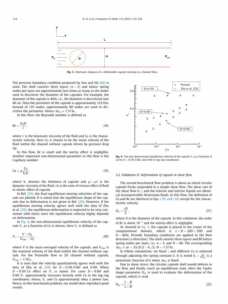
The first benchmark flow problem is the steady motion of acompliant capsule moving in a 2D rigid channel [29]. It shouldbe noticed that present numerical method is identical to that ofZhu et al. [29]. Fig. 3 shows the schematic diagram of this flowproblem. Initially the capsule is circular and placed midwaybetween the channel walls. In our simulations, the channel heightand length are H ¼ 54 lu and L ¼ 8H, respectively. The channel’supper and lower walls are assumed to be rigid. Three cases withD ¼ 0:5H;0:8H, and 0:9H are simulated, where D is the capsule’sinitial diameter. The flow is driven by a fixed pressure drop
between inlet and outlet boundaries Dp ¼ 1:44� 10�3mu=ðluts2Þ.
PoutPin DH
Lx
y
Fig. 3. Schematic diagram of a deformable capsule moving in a channel flow.
Ca
Vr
10-4 10-3 10-2 10-1
0.4
0.8
PresentZhu et al. [29]
D=0.9H
D=0.5H
D=0.8H
Fig. 4. The non-dimensional equilibrium velocity of the capsule Vr as a function ofCa for D ¼ 0:5H;0:8H, and 0:9H in log–log coordinates.
114 H. Ye et al. / Computers & Fluids 114 (2015) 110–120
The pressure boundary condition proposed by Zou and He [42] isused. The shell consists three layers (n ¼ 3) and lattice springnodes per layer are approximately two times as many as the nodesused to discretize the diameter of the capsules. For example, thediameter of the capsule is 40 lu, i.e., the diameter is discretized into40 Dx. Then the perimeter of the capsule is approximately 125:6 lu.Instead of 125 nodes, approximately 80 nodes are used to dis-cretize the perimeter. Hence DxLS � 1:57 lu.
In this flow, the Reynolds number is defined as
Re ¼ U0Dm
; ð18Þ
where m is the kinematic viscosity of the fluid and U0 is the charac-teristic velocity. Here U0 is chosen to be the mean velocity of thefluid within the channel without capsule driven by pressure dropDp.
In this flow, Re is small and the inertia effect is negligible.Another important non-dimensional parameter in this flow is theCapillary number:
Ca ¼ l U0
Eshc; ð19Þ
where hc denotes the thickness of capsule and l ¼ qm is thedynamic viscosity of the fluid. Ca is the ratio of viscous effect of fluidto elastic effect of capsule.
In Ref. [29], the final equilibrium moving velocities of the cap-sule are plotted. It is noted that the equilibrium shape of the cap-sule due to deformation is not given in Ref. [29]. However, if theequilibrium moving velocity agrees well with the data of Zhuet al. [29], the equilibrium deformation is expected to be very con-sistent with theirs since the equilibrium velocity highly dependson deformation.
In Fig. 4, the non-dimensional equilibrium velocity of the cap-sule Vr as a function of Ca is shown. Here Vr is defined as
Vr ¼V � U0
Umax � U0; ð20Þ
where V is the mass-averaged velocity of the capsule, and Umax isthe maximal velocity of the fluid within the channel without cap-sule. For the Poiseuille flow in 2D channel without capsule,Umax ¼ 1:5U0.
It is seen that the velocity quantitatively agrees well with thedata of Zhu et al. [29] for D ¼ 0:5H;0:8H and 0:9H. WhenD ¼ 0:5H;Ca effect on Vr is minor. For cases D ¼ 0:8H and0:9H;Vr approximately increases linearly with Ca in the log–logcoordinates. Hence, Vr and Ca approximately obey a power law.Hence, in this benchmark problem, our model does reproduce goodresults.
3.2. Validation II: Deformation of capsule in shear flow
The second benchmark flow problem is about an initial circularcapsule freely suspended in a simple shear flow. The shear rate ofthe shear flow is c, and the exterior and interior liquids are identi-cal incompressible Newtonian fluids. In this flow, the definition ofCa and Re are identical to Eqs. (19) and (18) except for the charac-teristic velocity
U0 ¼cD2; ð21Þ
where D is the diameter of the capsule. In this validation, the orderof Re is about 10�2 and the inertia effect is negligible.
As showed in Fig. 5, the capsule is placed in the center of thecomputational domain, which is L� H ¼ 20D� 20D andD ¼ 40 lu. Periodic boundary conditions are applied in the flowdirection (x-direction). The shell consists three layers and 80 latticespring nodes per layer, i.e., n ¼ 3, and N ¼ 80. The correspondingDxLS � Dr ¼ 2pðD=2� hs=2Þ=N ¼ 1:57 lu.
In follow simulations, we fixed c and different Ca is achievedthrough adjusting the spring constant k. It is noted Es ¼ 5k
2DxLSis a
monotonic function of k when DxLS is fixed.Due to shear stress, the circular capsule shell would deform in
the flow and finally reach an equilibrium state. Here the Taylorshape parameter Dxy is used to evaluate the deformation of thecapsule, which is read
Dxy ¼L� BLþ B
; ð22Þ
y
x
u= γ y
θ=−π/2
θ=π/2
θL
B
Fig. 5. Schematic of a capsule suspended in a shear flow.
H. Ye et al. / Computers & Fluids 114 (2015) 110–120 115
where L and B are the lengths of the semi-major and minor axes ofthe equilibrium elliptical capsule, respectively (see Fig. 5). h is theinclined angle (the major axis with respect to the horizontal x-axis).
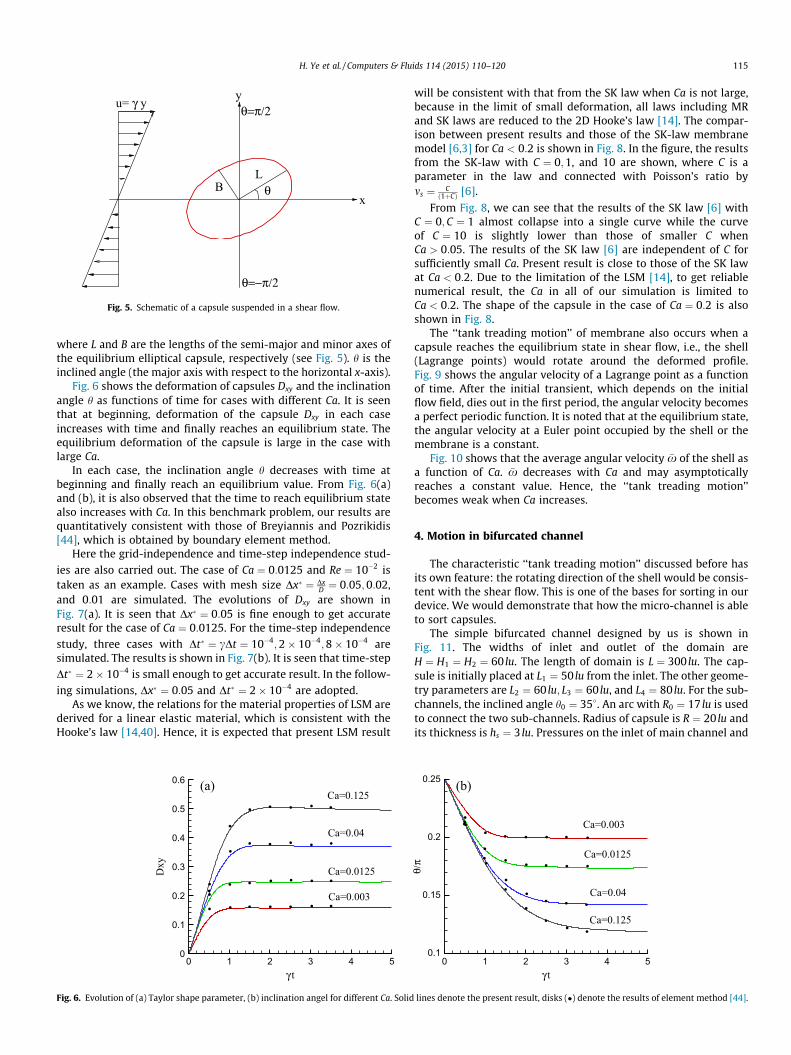
Fig. 6 shows the deformation of capsules Dxy and the inclinationangle h as functions of time for cases with different Ca. It is seenthat at beginning, deformation of the capsule Dxy in each caseincreases with time and finally reaches an equilibrium state. Theequilibrium deformation of the capsule is large in the case withlarge Ca.
In each case, the inclination angle h decreases with time atbeginning and finally reach an equilibrium value. From Fig. 6(a)and (b), it is also observed that the time to reach equilibrium statealso increases with Ca. In this benchmark problem, our results arequantitatively consistent with those of Breyiannis and Pozrikidis[44], which is obtained by boundary element method.
Here the grid-independence and time-step independence stud-ies are also carried out. The case of Ca ¼ 0:0125 and Re ¼ 10�2 istaken as an example. Cases with mesh size Dx ¼ Dx
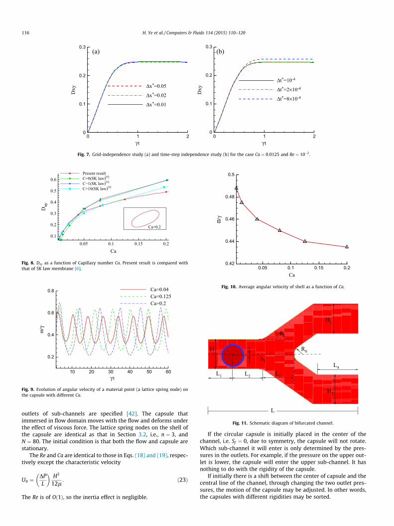
D ¼ 0:05;0:02,and 0:01 are simulated. The evolutions of Dxy are shown inFig. 7(a). It is seen that Dx ¼ 0:05 is fine enough to get accurateresult for the case of Ca ¼ 0:0125. For the time-step independencestudy, three cases with Dt ¼ cDt ¼ 10�4;2� 10�4;8� 10�4 aresimulated. The results is shown in Fig. 7(b). It is seen that time-stepDt ¼ 2� 10�4 is small enough to get accurate result. In the follow-ing simulations, Dx ¼ 0:05 and Dt ¼ 2� 10�4 are adopted.
As we know, the relations for the material properties of LSM arederived for a linear elastic material, which is consistent with theHooke’s law [14,40]. Hence, it is expected that present LSM result
Dxy
0 1 2 3 4 50
0.1
0.2
0.3
0.4
0.5
0.6Ca=0.125
Ca=0.04
Ca=0.0125
Ca=0.003
(a)
Fig. 6. Evolution of (a) Taylor shape parameter, (b) inclination angel for different Ca. Solid
will be consistent with that from the SK law when Ca is not large,because in the limit of small deformation, all laws including MRand SK laws are reduced to the 2D Hooke’s law [14]. The compar-ison between present results and those of the SK-law membranemodel [6,3] for Ca < 0:2 is shown in Fig. 8. In the figure, the resultsfrom the SK-law with C ¼ 0;1, and 10 are shown, where C is aparameter in the law and connected with Poisson’s ratio byms ¼ C
ð1þCÞ [6].
From Fig. 8, we can see that the results of the SK law [6] withC ¼ 0; C ¼ 1 almost collapse into a single curve while the curveof C ¼ 10 is slightly lower than those of smaller C whenCa > 0:05. The results of the SK law [6] are independent of C forsufficiently small Ca. Present result is close to those of the SK lawat Ca < 0:2. Due to the limitation of the LSM [14], to get reliablenumerical result, the Ca in all of our simulation is limited toCa < 0:2. The shape of the capsule in the case of Ca ¼ 0:2 is alsoshown in Fig. 8.
The ‘‘tank treading motion’’ of membrane also occurs when acapsule reaches the equilibrium state in shear flow, i.e., the shell(Lagrange points) would rotate around the deformed profile.Fig. 9 shows the angular velocity of a Lagrange point as a functionof time. After the initial transient, which depends on the initialflow field, dies out in the first period, the angular velocity becomesa perfect periodic function. It is noted that at the equilibrium state,the angular velocity at a Euler point occupied by the shell or themembrane is a constant.
Fig. 10 shows that the average angular velocity �x of the shell asa function of Ca. �x decreases with Ca and may asymptoticallyreaches a constant value. Hence, the ‘‘tank treading motion’’becomes weak when Ca increases.
4. Motion in bifurcated channel
The characteristic ‘‘tank treading motion’’ discussed before hasits own feature: the rotating direction of the shell would be consis-tent with the shear flow. This is one of the bases for sorting in ourdevice. We would demonstrate that how the micro-channel is ableto sort capsules.
The simple bifurcated channel designed by us is shown inFig. 11. The widths of inlet and outlet of the domain areH ¼ H1 ¼ H2 ¼ 60 lu. The length of domain is L ¼ 300 lu. The cap-sule is initially placed at L1 ¼ 50 lu from the inlet. The other geome-try parameters are L2 ¼ 60 lu; L3 ¼ 60 lu, and L4 ¼ 80 lu. For the sub-channels, the inclined angle h0 ¼ 35�. An arc with R0 ¼ 17 lu is usedto connect the two sub-channels. Radius of capsule is R ¼ 20 lu andits thickness is hs ¼ 3 lu. Pressures on the inlet of main channel and
θ/π
0 1 2 3 4 50.1
0.15
0.2
0.25
Ca=0.003
Ca=0.0125
Ca=0.04
Ca=0.125
(b)
lines denote the present result, disks (�) denote the results of element method [44].
Dxy
0 1 20
0.1
0.2
0.3
Δt*=10-4
Δt*=2×10⁻⁴
Δt*=8×10⁻⁴
(b)
Dxy
0 1 20
0.1
0.2
0.3
Δx*=0.05
Δx*=0.02
Δx*=0.01
(a)
Fig. 7. Grid-independence study (a) and time-step independence study (b) for the case Ca ¼ 0:0125 and Re ¼ 10�2.
Ca
Dxy
0.05 0.1 0.15 0.2
0.1
0.2
0.3
0.4
0.5
0.6Present resultC=0(SK law)[6]
C=1(SK law)[6]
C=10(SK law)[6]
Ca=0.2
Fig. 8. Dxy as a function of Capillary number Ca. Present result is compared withthat of SK law membrane [6].
ω/γ
10 20 30 40 50 60
0.2
0.4
0.6
0.8 Ca=0.04Ca=0.125Ca=0.2
Fig. 9. Evolution of angular velocity of a material point (a lattice spring node) onthe capsule with different Ca.
Ca0.05 0.1 0.15 0.2
0.42
0.44
0.46
0.48
0.5
ω/γ
Fig. 10. Average angular velocity of shell as a function of Ca.
R0H
L3
H2
H1
L4
L1
θ0
Sf
L2
L
Fig. 11. Schematic diagram of bifurcated channel.
116 H. Ye et al. / Computers & Fluids 114 (2015) 110–120
outlets of sub-channels are specified [42]. The capsule thatimmersed in flow domain moves with the flow and deforms underthe effect of viscous force. The lattice spring nodes on the shell ofthe capsule are identical as that in Section 3.2, i.e., n ¼ 3, andN ¼ 80. The initial condition is that both the flow and capsule arestationary.
The Re and Ca are identical to those in Eqs. (18) and (19), respec-tively except the characteristic velocity
U0 ¼DPL
� �H2
12l: ð23Þ
The Re is of Oð1Þ, so the inertia effect is negligible.
If the circular capsule is initially placed in the center of thechannel, i.e. Sf ¼ 0, due to symmetry, the capsule will not rotate.Which sub-channel it will enter is only determined by the pres-sures in the outlets. For example, if the pressure on the upper out-let is lower, the capsule will enter the upper sub-channel. It hasnothing to do with the rigidity of the capsule.
If initially there is a shift between the center of capsule and thecentral line of the channel, through changing the two outlet pres-sures, the motion of the capsule may be adjusted. In other words,the capsules with different rigidities may be sorted.
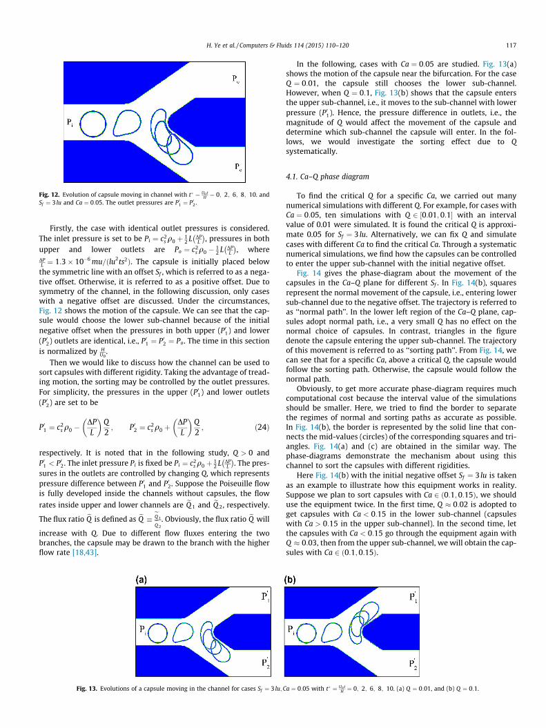
Fig. 12. Evolution of capsule moving in channel with t ¼ U0 tH ¼ 0; 2; 6; 8; 10. and
Sf ¼ 3 lu and Ca ¼ 0:05. The outlet pressures are P01 ¼ P02.
H. Ye et al. / Computers & Fluids 114 (2015) 110–120 117
Firstly, the case with identical outlet pressures is considered.The inlet pressure is set to be Pi ¼ c2
s q0 þ 12 L DP
L
� �, pressures in both
upper and lower outlets are Po ¼ c2s q0 � 1
2 L DPL
� �, where
DPL ¼ 1:3� 10�6 mu=ðlu2ts2Þ. The capsule is initially placed below
the symmetric line with an offset Sf , which is referred to as a nega-tive offset. Otherwise, it is referred to as a positive offset. Due tosymmetry of the channel, in the following discussion, only caseswith a negative offset are discussed. Under the circumstances,Fig. 12 shows the motion of the capsule. We can see that the cap-sule would choose the lower sub-channel because of the initialnegative offset when the pressures in both upper (P01) and lower(P02) outlets are identical, i.e., P01 ¼ P02 ¼ Po. The time in this sectionis normalized by H
U0.
Then we would like to discuss how the channel can be used tosort capsules with different rigidity. Taking the advantage of tread-ing motion, the sorting may be controlled by the outlet pressures.For simplicity, the pressures in the upper (P01) and lower outlets(P02) are set to be
P01 ¼ c2s q0 �
DPL
� �Q2; P02 ¼ c2
s q0 þDPL
� �Q2; ð24Þ
respectively. It is noted that in the following study, Q > 0 andP01 < P02. The inlet pressure Pi is fixed be Pi ¼ c2
s q0 þ 12 L DP
L
� �. The pres-
sures in the outlets are controlled by changing Q, which representspressure difference between P01 and P02. Suppose the Poiseuille flowis fully developed inside the channels without capsules, the flow
rates inside upper and lower channels are eQ 1 and eQ 2, respectively.
The flux ratio eQ is defined as eQ eQ 1eQ 2
. Obviously, the flux ratio eQ will
increase with Q. Due to different flow fluxes entering the twobranches, the capsule may be drawn to the branch with the higherflow rate [18,43].
Fig. 13. Evolutions of a capsule moving in the channel for cases Sf ¼ 3 lu;C
In the following, cases with Ca ¼ 0:05 are studied. Fig. 13(a)shows the motion of the capsule near the bifurcation. For the caseQ ¼ 0:01, the capsule still chooses the lower sub-channel.However, when Q ¼ 0:1, Fig. 13(b) shows that the capsule entersthe upper sub-channel, i.e., it moves to the sub-channel with lowerpressure (P01). Hence, the pressure difference in outlets, i.e., themagnitude of Q would affect the movement of the capsule anddetermine which sub-channel the capsule will enter. In the fol-lows, we would investigate the sorting effect due to Qsystematically.
4.1. Ca–Q phase diagram
To find the critical Q for a specific Ca, we carried out manynumerical simulations with different Q. For example, for cases withCa ¼ 0:05, ten simulations with Q 2 ½0:01; 0:1� with an intervalvalue of 0.01 were simulated. It is found the critical Q is approxi-mate 0.05 for Sf ¼ 3 lu. Alternatively, we can fix Q and simulatecases with different Ca to find the critical Ca. Through a systematicnumerical simulations, we find how the capsules can be controlledto enter the upper sub-channel with the initial negative offset.
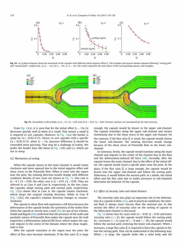
Fig. 14 gives the phase-diagram about the movement of thecapsules in the Ca–Q plane for different Sf . In Fig. 14(b), squaresrepresent the normal movement of the capsule, i.e., entering lowersub-channel due to the negative offset. The trajectory is referred toas ‘‘normal path’’. In the lower left region of the Ca–Q plane, cap-sules adopt normal path, i.e., a very small Q has no effect on thenormal choice of capsules. In contrast, triangles in the figuredenote the capsule entering the upper sub-channel. The trajectoryof this movement is referred to as ‘‘sorting path’’. From Fig. 14, wecan see that for a specific Ca, above a critical Q, the capsule wouldfollow the sorting path. Otherwise, the capsule would follow thenormal path.
Obviously, to get more accurate phase-diagram requires muchcomputational cost because the interval value of the simulationsshould be smaller. Here, we tried to find the border to separatethe regimes of normal and sorting paths as accurate as possible.In Fig. 14(b), the border is represented by the solid line that con-nects the mid-values (circles) of the corresponding squares and tri-angles. Fig. 14(a) and (c) are obtained in the similar way. Thephase-diagrams demonstrate the mechanism about using thischannel to sort the capsules with different rigidities.
Here Fig. 14(b) with the initial negative offset Sf ¼ 3 lu is takenas an example to illustrate how this equipment works in reality.Suppose we plan to sort capsules with Ca 2 ð0:1;0:15Þ, we shoulduse the equipment twice. In the first time, Q � 0:02 is adopted toget capsules with Ca < 0:15 in the lower sub-channel (capsuleswith Ca > 0:15 in the upper sub-channel). In the second time, letthe capsules with Ca < 0:15 go through the equipment again withQ � 0:03, then from the upper sub-channel, we will obtain the cap-sules with Ca 2 ð0:1;0:15Þ.
a ¼ 0:05 with t ¼ U0 tH ¼ 0; 2; 6; 8; 10. (a) Q ¼ 0:01, and (b) Q ¼ 0:1.
Q
Ca
0 0.02 0.04 0.06 0.080
0.1
0.2(c) Sf=5
Q
Ca
0 0.02 0.04 0.06 0.080
0.1
0.2
sorting region
normal region
(b) Sf=3
Q
Ca
0 0.02 0.04 0.06 0.080
0.1
0.2(a) Sf=1
Fig. 14. Ca–Q phase-diagram about the movement of the capsules with different initial negative offset Sf . The triangles and squares denote capsules following ‘‘sorting path’’and ‘‘normal path’’, respectively. (a) Sf ¼ 1 lu, (b) Sf ¼ 3 lu, (c) Sf ¼ 5 lu. The circles represent the mid-values of the corresponding squares and triangles.
Fig. 15. Streamlines in flow fields (a) Q ¼ 0:1;Ca ¼ 0:05 and (b) Q ¼ 0:01;Ca ¼ 0:05. Pressure contours are normalized by the inlet pressure.
118 H. Ye et al. / Computers & Fluids 114 (2015) 110–120
From Fig. 14(a), it is seen that for the initial offset Sf ¼ 1 lu;Cadecreases quickly with Q when Q is small. That means a small Qis required to sort capsules. However, in Fig. 14(a) the border issteep for Ca 2 ð0:02;0:15Þ. Hence, to sort capsules with a specificCa 2 ð0:02;0:15Þ when Sf ¼ 1 lu, pressure difference Q should becontrolled more precisely. That may be a challenge in reality. Weprefer the border lines like those in Fig. 14(b) and (c), which arenot so steep.
4.2. Mechanism of sorting
When the capsule moves in the main channel, it would rotateclockwise and move upward due to the initial negative offset andshear stress in the Poiseuille flow. When it enter into the regionnear the joint, the rotating direction would change with differentcondition. Results of two cases are shown in Fig. 15. One case isQ ¼ 0:1;Ca ¼ 0:05, the other case is Q ¼ 0:01;Ca ¼ 0:05. They arereferred to as Case A and Case B, respectively. In the two cases,the capsules adopt sorting path and normal path, respectively.Fig. 15(a) shows that in Case A, the capsule rotates clockwise,which keeps the original rotating direction. While in Case B(Fig. 15(b)), the capsule’s rotation direction changes to counter-clockwise.
The capsule in shear flow will experience a lift force because thedeformation of the capsule breaks the symmetry of the stokes flowwhen the capsule or vesicle near a wall [45]. In case of our scheme,Doddi and Bagchi [46] confirmed that the presence of the walls andparabolic nature of Poiseuille flow makes the capsule near the wallexperience a deformation-induced lift force, which makes the cap-sule migrate to the center of the domain where the shear magni-tude is low.
After the capsule translates to the region near the joint, the
effect of flux ratio becomes dominant. If the flux ratio eQ is large
enough, the capsule would be drawn to the upper sub-channel.The capsule translates along the upper sub-channel and rotatesclockwisely due to the shear stress in the upper sub-channel. On
the contrary, if the flux ratio eQ is small, the capsule would choosethe lower sub-channel. The rotating direction would changebecause of the shear stress of Poiseuille flow in the lower sub-channel.
In summary, firstly, the capsule would translate along the mainchannel and migrate to the center of the channel due to the flowand the deformation-induced lift force [46]. Secondly, after thecapsule leaves the main channel, due to the effect of the initial off-set, the capsule would reach a specific place near the joint. At the
place, if the flux ratio eQ is large enough, the capsule would bedrawn into the upper sub-channel and follow the sorting path.Otherwise, it would follow the normal path. In a whole, the initialoffset and the flux ratio due to outlet pressures in sub-channelsdetermine the behavior of the capsule.
4.3. Effect of viscosity ratio and initial distance
The viscosity ratio also plays an important role in the deforma-tion of a capsule in flow [4,5], and in practical conditions, the inter-nal fluid is always more viscous than the external one. In thissection the effect of viscosity ratio on the sorting of capsule inthe bifurcated channel is discussed.
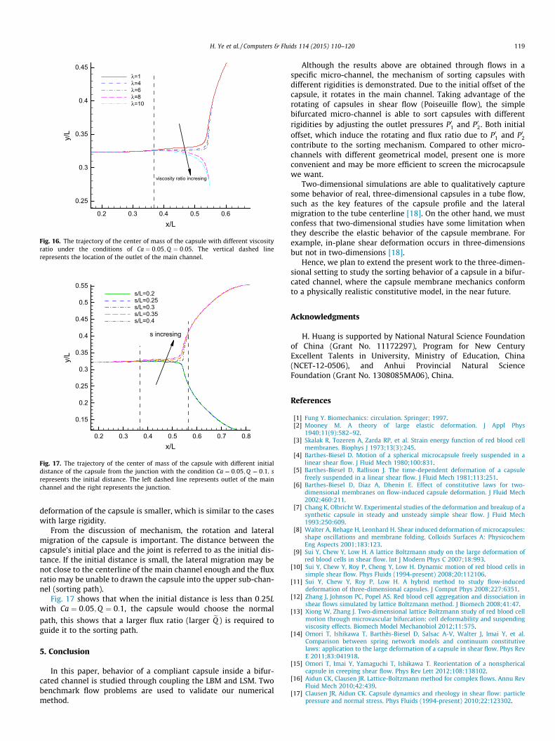
Fig. 16 shows that for cases with Ca ¼ 0:05;Q ¼ 0:05 and lowerviscosity ratio (k 6 6), the capsule would follow the sorting path.As k increases (k > 6, cases of k ¼ 8 and k ¼ 10), the capsule wouldfollow the normal path (entering the lower sub-channel). When k
increases, a large flux ratio eQ is required to force the capsule to fol-low the sorting path. That can be understood in the following way.When k is large, the capsule looks like a solid body and the
x/L
y/L
0.2 0.3 0.4 0.5 0.6
0.25
0.3
0.35
0.4
0.45λ=1λ=4λ=6λ=8λ=10
viscosity ratio incresing
Fig. 16. The trajectory of the center of mass of the capsule with different viscosityratio under the conditions of Ca ¼ 0:05;Q ¼ 0:05. The vertical dashed linerepresents the location of the outlet of the main channel.
x/L
y/L
0.2 0.3 0.4 0.5 0.6 0.7 0.8
0.15
0.2
0.25
0.3
0.35
0.4
0.45
0.5
0.55s/L=0.2s/L=0.25s/L=0.3s/L=0.35s/L=0.4
s incresing
Fig. 17. The trajectory of the center of mass of the capsule with different initialdistance of the capsule from the junction with the condition Ca ¼ 0:05;Q ¼ 0:1. srepresents the initial distance. The left dashed line represents outlet of the mainchannel and the right represents the junction.
H. Ye et al. / Computers & Fluids 114 (2015) 110–120 119
deformation of the capsule is smaller, which is similar to the caseswith large rigidity.
From the discussion of mechanism, the rotation and lateralmigration of the capsule is important. The distance between thecapsule’s initial place and the joint is referred to as the initial dis-tance. If the initial distance is small, the lateral migration may benot close to the centerline of the main channel enough and the fluxratio may be unable to drawn the capsule into the upper sub-chan-nel (sorting path).
Fig. 17 shows that when the initial distance is less than 0:25Lwith Ca ¼ 0:05;Q ¼ 0:1, the capsule would choose the normal
path, this shows that a larger flux ratio (larger eQ ) is required toguide it to the sorting path.
5. Conclusion
In this paper, behavior of a compliant capsule inside a bifur-cated channel is studied through coupling the LBM and LSM. Twobenchmark flow problems are used to validate our numericalmethod.
Although the results above are obtained through flows in aspecific micro-channel, the mechanism of sorting capsules withdifferent rigidities is demonstrated. Due to the initial offset of thecapsule, it rotates in the main channel. Taking advantage of therotating of capsules in shear flow (Poiseuille flow), the simplebifurcated micro-channel is able to sort capsules with differentrigidities by adjusting the outlet pressures P01 and P02. Both initialoffset, which induce the rotating and flux ratio due to P01 and P02contribute to the sorting mechanism. Compared to other micro-channels with different geometrical model, present one is moreconvenient and may be more efficient to screen the microcapsulewe want.
Two-dimensional simulations are able to qualitatively capturesome behavior of real, three-dimensional capsules in a tube flow,such as the key features of the capsule profile and the lateralmigration to the tube centerline [18]. On the other hand, we mustconfess that two-dimensional studies have some limitation whenthey describe the elastic behavior of the capsule membrane. Forexample, in-plane shear deformation occurs in three-dimensionsbut not in two-dimensions [18].
Hence, we plan to extend the present work to the three-dimen-sional setting to study the sorting behavior of a capsule in a bifur-cated channel, where the capsule membrane mechanics conformto a physically realistic constitutive model, in the near future.
Acknowledgments
H. Huang is supported by National Natural Science Foundationof China (Grant No. 11172297), Program for New CenturyExcellent Talents in University, Ministry of Education, China(NCET-12-0506), and Anhui Provincial Natural ScienceFoundation (Grant No. 1308085MA06), China.
References
[1] Fung Y. Biomechanics: circulation. Springer; 1997.[2] Mooney M. A theory of large elastic deformation. J Appl Phys
1940;11(9):582–92.[3] Skalak R, Tozeren A, Zarda RP, et al. Strain energy function of red blood cell
membranes. Biophys J 1973;13(3):245.[4] Barthes-Biesel D. Motion of a spherical microcapsule freely suspended in a
linear shear flow. J Fluid Mech 1980;100:831.[5] Barthes-Biesel D, Rallison J. The time-dependent deformation of a capsule
freely suspended in a linear shear flow. J Fluid Mech 1981;113:251.[6] Barthes-Biesel D, Diaz A, Dhenin E. Effect of constitutive laws for two-
dimensional membranes on flow-induced capsule deformation. J Fluid Mech2002;460:211.
[7] Chang K, Olbricht W. Experimental studies of the deformation and breakup of asynthetic capsule in steady and unsteady simple shear flow. J Fluid Mech1993;250:609.
[8] Walter A, Rehage H, Leonhard H. Shear induced deformation of microcapsules:shape oscillations and membrane folding. Colloids Surfaces A: PhysicochemEng Aspects 2001;183:123.
[9] Sui Y, Chew Y, Low H. A lattice Boltzmann study on the large deformation ofred blood cells in shear flow. Int J Modern Phys C 2007;18:993.
[10] Sui Y, Chew Y, Roy P, Cheng Y, Low H. Dynamic motion of red blood cells insimple shear flow. Phys Fluids (1994-present) 2008;20:112106.
[11] Sui Y, Chew Y, Roy P, Low H. A hybrid method to study flow-induceddeformation of three-dimensional capsules. J Comput Phys 2008;227:6351.
[12] Zhang J, Johnson PC, Popel AS. Red blood cell aggregation and dissociation inshear flows simulated by lattice Boltzmann method. J Biomech 2008;41:47.
[13] Xiong W, Zhang J. Two-dimensional lattice Boltzmann study of red blood cellmotion through microvascular bifurcation: cell deformability and suspendingviscosity effects. Biomech Model Mechanobiol 2012;11:575.
[14] Omori T, Ishikawa T, Barthès-Biesel D, Salsac A-V, Walter J, Imai Y, et al.Comparison between spring network models and continuum constitutivelaws: application to the large deformation of a capsule in shear flow. Phys RevE 2011;83:041918.
[15] Omori T, Imai Y, Yamaguchi T, Ishikawa T. Reorientation of a nonsphericalcapsule in creeping shear flow. Phys Rev Lett 2012;108:138102.
[16] Aidun CK, Clausen JR. Lattice-Boltzmann method for complex flows. Annu RevFluid Mech 2010;42:439.
[17] Clausen JR, Aidun CK. Capsule dynamics and rheology in shear flow: particlepressure and normal stress. Phys Fluids (1994-present) 2010;22:123302.
120 H. Ye et al. / Computers & Fluids 114 (2015) 110–120
[18] Woolfenden H, Blyth M. Motion of a two-dimensional elastic capsule in abranching channel flow. J Fluid Mech 2011;669:3.
[19] Peskin CS. The immersed boundary method. Acta Numer 2002;11.[20] Feng Z-G, Michaelides EE. Proteus: a direct forcing method in the simulations
of particulate flows. J Comput Phys 2005;202:20.[21] MacMeccan RM, Clausen J, Neitzel G, Aidun C. Simulating deformable particle
suspensions using a coupled lattice-Boltzmann and finite-element method. JFluid Mech 2009;618:13.
[22] Keller SR, Skalak R. Motion of a tank-treading ellipsoidal particle in a shearflow. J Fluid Mech 1982;120:27.
[23] Abkarian M, Faivre M, Viallat A. Swinging of red blood cells under shear flow.Phys Rev Lett 2007;98:188302.
[24] Skotheim J, Secomb T. Red blood cells and other nonspherical capsules in shearflow: oscillatory dynamics and the tank-treading-to-tumbling transition. PhysRev Lett 2007;98:078301.
[25] Kessler S, Finken R, Seifert U. Swinging and tumbling of elastic capsules inshear flow. J Fluid Mech 2008;605:207.
[26] Alexeev A, Verberg R, Balazs AC. Designing compliant substrates to regulatethe motion of vesicles. Phys Rev Lett 2006;96:148103.
[27] Alexeev A, Verberg R, Balazs AC. Motion of compliant capsules on corrugatedsurfaces: a means of sorting by mechanical properties. J Polym Sci Part B:Polym Phys 2006;44:2667.
[28] Alexeev A, Verberg R, Balazs AC. Modeling the motion of microcapsules oncompliant polymeric surfaces. Macromolecules 2005;38:10244.
[29] Zhu G, Alexeev A, Kumacheva E, Balazs AC. Modeling the interactions betweencompliant microcapsules and pillars in microchannels. J Chem Phys2007;127:034703.
[30] Hyakutake T, Matsumoto T, Yanase S. Lattice Boltzmann simulation of bloodcell behavior at microvascular bifurcations. Math Comput Simul 2006;72:134.
[31] Barber JO, Alberding JP, Restrepo JM, Secomb TW. Simulated two-dimensionalred blood cell motion, deformation, and partitioning in microvesselbifurcations. Ann Biomed Eng 2008;36:1690.
[32] Pazdniakou A, Adler P. Lattice spring models. Transport Porous Media2012;93:243.
[33] Buxton G, Verberg R, Jasnow D, Balazs A. Newtonian fluid meets an elasticsolid: coupling lattice Boltzmann and lattice-spring models. Phys Rev E2005;71:056707.
[34] Buxton GA, Care CM, Cleaver DJ. A lattice spring model of heterogeneousmaterials with plasticity. Modell Simul Mater Sci Eng 2001;9(6):485.
[35] Ostoja-Starzewski M. Lattice models in micromechanics. Appl Mech Rev2002;55:35.
[36] He X, Luo L-S. Theory of the lattice Boltzmann method: from the Boltzmannequation to the lattice Boltzmann equation. Phys Rev E 1997;56:6811.
[37] Lallemand P, Luo L-S. Lattice Boltzmann method for moving boundaries. JComput Phys 2003;184:406.
[38] Bouzidi M, Firdaouss M, Lallemand P. Momentum transfer of a Boltzmann-lattice fluid with boundaries. Phys Fluids (1994-present) 2001;13:3452.
[39] Ladd AJ, Kinney JH. Elastic constants of cellular structures. Phys A: Stat MechAppl 1997;240:349.
[40] Kilimnik A, Mao W, Alexeev A. Inertial migration of deformable capsules inchannel flow. Phys Fluids (1994-present) 2011;23:123302.
[41] Schwartz LM, Feng S, Thorpe M, Sen PN. Behavior of depleted elastic networks:comparison of effective-medium and numerical calculations. Phys Rev B1985;32:4607.
[42] Zou Q, He X. On pressure and velocity boundary conditions for the latticeBoltzmann BGK model. Phys Fluids (1994-present) 1997;9:1591.
[43] Fung YC. Stochastic flow in capillary blood vessels. Microvasc Res1973;5(1):34C48.
[44] Breyiannis G, Pozrikidis C. Simple shear flow of suspensions of elastic capsules.Theor Comput Fluid Dynam 2000;13:327.
[45] Olla, Piero. The lift on a tank-treading ellipsoidal cell in a shear flow. J Phys II1997;10:7.
[46] Doddi Sai K, Bagchi Prosenjit. Lateral migration of a capsule in a planePoiseuille flow in a channel. Int J Multiphase Flow 2008;10:34.


![Forcing term in single-phase and Shan-Chen-type multiphase ...staff.ustc.edu.cn/~huanghb/2011_PRE_Huang_krafczyk.pdf · theforcingtermintheLBM,fiveofwhich[1,5,7–10],labeled I–V,](https://img.pdfslide.us/doc/110x75/601af68a3f863024af308177/forcing-term-in-single-phase-and-shan-chen-type-multiphase-staffustceducnhuanghb2011prehuang.jpg)