Embed Size (px)
Citation preview

Computer Simulation, Mathematical Model, and Experimental Analysis of Severe Slugging in a Riser
Daniel Schmidt (LSU Petroleum Engineering student)
Mentors: Dr. Mayank Tyagi (PETE Dept.) and Dr. Michael Malisoff (Math Dept.)
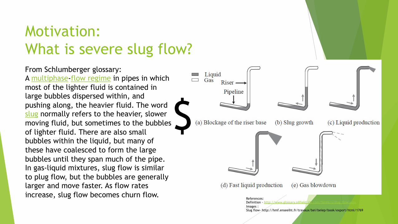
Motivation: What is severe slug flow? From Schlumberger glossary: A multiphase-flow regime in pipes in which most of the lighter fluid is contained in large bubbles dispersed within, and pushing along, the heavier fluid. The word slug normally refers to the heavier, slower moving fluid, but sometimes to the bubbles of lighter fluid. There are also small bubbles within the liquid, but many of these have coalesced to form the large bubbles until they span much of the pipe. In gas-liquid mixtures, slug flow is similar to plug flow, but the bubbles are generally larger and move faster. As flow rates increase, slug flow becomes churn flow.
References: Definition - http://www.glossary.oilfield.slb.com/Terms/s/slug_flow.aspx Images : Slug flow- http://hmf.enseeiht.fr/travaux/bei/beiep/book/export/html/1769
$

Mathematical model
u From Di Meglio et. al. for using with a control on the slug flow process
u Consists of three differential equations:
Mass of gas in bubble
Mass of gas in riser / mass of liquid in riser
Mass of liquid in riser References: F. Di Meglio, G. –O Kaasa, N. Petit, and V. Alstad,”Model-based control of slugging flow: an experimental case study,”.

CFD Simulation: ANSYS FLUENT
u Similar geometry to experimental setup: pipe diameter and distances
u Input flow rate for gas and water
u Mesh consisted of 17056 nodes
u Solves for mass, momentum balance, phase field and performs linear interpolation to gather data
VOF:
Momentum:
**** All equations and pictures were all taken from the ANSYS FLUENT Academic version and its corresponding manual

FLUENT Animation

Experimental Setup
• Pressure sensor at choke valve
• Riser
• Flow meter
• Air flow meter
• Pressure sensor (base)
• Air compressor
• Water pump


Data Comparison
Experimental
CFD Simulation
Mathematical Model

Questions?
Special thanks to the following people for help with:
Ø Micheal Schmidt – (model design and fabrication)
Ø Jim Shafer – (electrical)
Ø Daniel Barreca – (CFD simulation)
Ø Kathleen Schmidt – (aesthetics)
Ø CCT and NSF (this experience)
Ø Dr. Richard Hughes & Campanile charities (model funding)
***This material is based upon work supported by the National Science Foundation under award OCI-1560410 with additional support from the Center for Computation & Technology at Louisiana State University