Embed Size (px)
Citation preview
CS 2363 / CS 65 – COMPUTER NETWORKS UNIT - I Electrical and Electronics Engineering
P.ANANTH [M.E, MCSE, CCNA], Lecturer CSE Feedback Mail To: [email protected] Page 1
UNIT- I Introduction to networks – network architecture – network performance – Direct link networks –
encoding – framing – error detection – transmision – Ethernet – Rings – FDDI - Wireles networks – Switched networks – bridges.
Def ine Network? (May/June’12 – 2Mark)
Def ine computer networks? (Nov/Dec’11 – 2Mark)
Network It is a set of devices connected by communication links. This device can be a computer, mobile, printer or anything else which is capable of sending
and receiving information / data.
Networking Networking is a connecting of two or more computing devices together for the purpose of
haring data and resources.
Purpose of Networking
Computer networks can be used for a variety of purposes, 1. Sharing hardware
In a networked environment, each computer on a network may access and use hardware
resources on the network, such as printing a document on a shared network printer.
2. Sharing files, data, and information
In a network environment, authorized user may access data and information stored on
other computers on the network. The capability of providing access to data and information on
hared storage devices is an important feature of many networks. 3. Sharing software
Users connected to a network may run application programs on remote computers. 4. Facilitating communications
Using a network, people can communicate efficiently and easily via email, instant
mesaging, chat rooms, telephone, video telephone calls, and video conferencing. 5. Security
Give the basic building blocks of network? (Nov/Dec’12 – 2Mark)
1. Computer (Client or Server).
2. Networking Devices (Hub, Bridge, Switch, and Router).
3. Physical Connectivity. (Wired or Wireles).
4. Protocols.
De fine protocol? (May/June ’11 –
2Mark) Protocol is a set of rules that govern data communications. A protocol defines what is
communicated, how it communicated and when it is communicated. The key elements of
protocol are syntax, semantics and timing.
Introduction to Networks
CS 2363 / CS 65 – COMPUTER NETWORKS UNIT - I Electrical and Electronics Engineering
P.ANANTH [M.E, MCSE, CCNA], Lecturer CSE Feedback Mail To: [email protected] Page 2
Describe network architecture in detail? (Nov/Dec’11 – 8Mark)
Discuss about the architecture of computer network with sketches? (Nov/Dec’12 – 8Mark)
With a neat block diagram explain the layered architecture? (Nov/Dec’11 – 16Mark)
Write short notes on network model? (May/June’12 – 4Mark)
Network Architecture
A scomputer snetwork vmust vprovide sgeneral, scost veffective, sfair sand srobust
connectivity among a large number of computers. Designing a network to meet these
requirements is no small task.
To deal with this complexity, network designers have developed general blue prints
– usually called network architectures. It guides the design and implementation
of networks.
The most widely referenced architectures,
- OSI architecture.
- Internet architecture.
Layering and Protocols
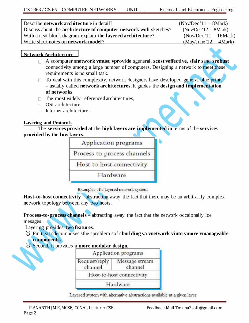
The services provided at the high layers are implemented in terms of the services
provided by the low layers.
Host-to-host connectivity – abstracting away the fact that there may be an arbitrarily complex
network topology between any two hosts.
Process-to-process channels – abtracting away the fact that the network occaionally loe
mesages.
Layering provides two features. Fir t, sit sdecomposes sthe sproblem sof sbuilding va vnetwork vinto vmore vmanageable
components. Second, it provides a more modular design.
CS 2363 / CS 65 – COMPUTER NETWORKS UNIT - I Electrical and Electronics Engineering
P.ANANTH [M.E, MCSE, CCNA], Lecturer CSE Feedback Mail To: [email protected] Page 3
The abstract objects that make up the layers of a network system are called protocols. ie) sa sprotocol sprovides sa scommunication service sthat shigher s– slevel sobjects ( such as
application processes, or perhaps higher – level protocols ) use to exchange messages.
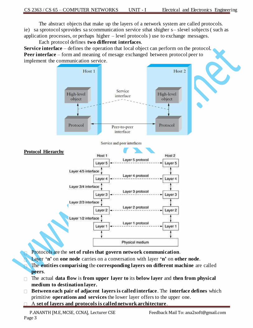
Each protocol defines two different interfaces.
Service interface – defines the operation that local object can perform on the protocol.
Peer interface – form and meaning of mesage exchanged between protocol peer to
implement the communication service.
Protocol Hierarchy
Protocols are the set of rules that govern network communication.
Layer ‘n’ on one node carries on a conversation with layer ‘n’ on other node.
The entities comparising the corresponding layers on different machine are called
peers.
The actual data flow is from upper layer to its below layer and then from physical
medium to destination layer.
Between each pair of adjacent layers is called interface . The interface defines which
primitive operations and services the lower layer offers to the upper one.
A set of layers and protocols is called network architecture .
CS 2363 / CS 65 – COMPUTER NETWORKS UNIT - I Electrical and Electronics Engineering
P.ANANTH [M.E, MCSE, CCNA], Lecturer CSE Feedback Mail To: [email protected] Page 4
ISO /OSI Reference Model
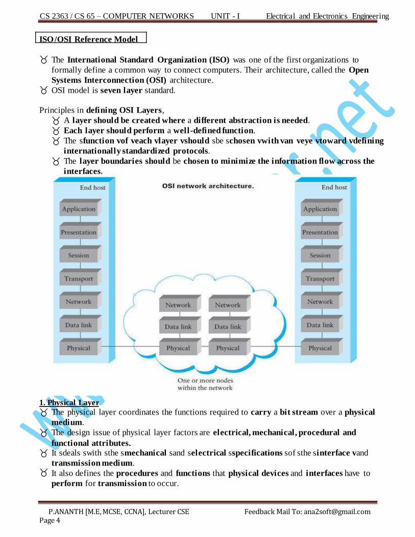
The International Standard Organization (ISO) was one of the first organizations to
formally define a common way to connect computers. Their architecture, called the Open
Systems Interconnection (OSI) architecture. OSI model is seven layer standard.
Principles in defining OSI Layers,
A layer should be created where a different abstraction is needed.
Each layer should perform a well-defined function.
The sfunction vof veach vlayer vshould sbe schosen vwith van veye vtoward vdefining
internationally standardized protocols.
The layer boundaries should be chosen to minimize the information flow across the
interfaces.
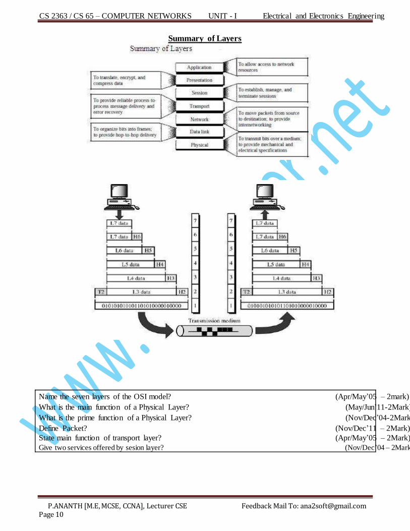
1. Physical Layer
The physical layer coordinates the functions required to carry a bit stream over a physical
medium.
The design issue of physical layer factors are electrical, mechanical, procedural and
functional attributes. It sdeals swith sthe smechanical sand selectrical sspecifications sof sthe sinterface vand
transmission medium. It also defines the procedures and functions that physical devices and interfaces have to
perform for transmission to occur.
CS 2363 / CS 65 – COMPUTER NETWORKS UNIT - I Electrical and Electronics Engineering
P.ANANTH [M.E, MCSE, CCNA], Lecturer CSE Feedback Mail To: [email protected] Page 5
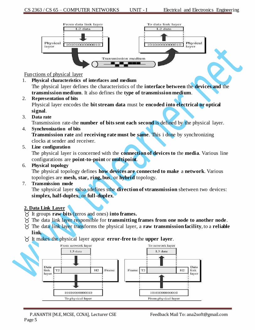
Fun ctions of physical layer
1. Physical characteristics of interfaces and medium
The physical layer defines the characteristics of the interface between the devices and the
transmission medium. It also defines the type of transmission medium. 2. Representation of bits
Physical layer encodes the bit stream data must be encoded into electrical or optical
signal. 3. Data rate
Transmission rate-the number of bits sent each second is defined by the physical layer. 4. Synchronization of bits
Transmission rate and receiving rate must be same. This i done by synchronizing
clocks at sender and receiver. 5. Line configuration
The physical layer is concerned with the connection of devices to the media. Various line
configurations are point-to-point or multipoint. 6. Physical topology
The physical topology defines how devices are connected to make a network. Various
topologies are mesh, star, ring, bus, or hybrid topology. 7. Transmission mode
The sphysical layer salso sdefines sthe direction of vtransmission sbetween two devices:
simplex, half-duplex, or full-duplex.
2. Data Link Layer
It groups raw bits (zeros and ones) into frames.
The data link layer responsible for transmitting frames from one node to another node .
The data link layer transforms the physical layer, a raw transmission facility, to a reliable
link.
It makes the physical layer appear error-free to the upper layer.
CS 2363 / CS 65 – COMPUTER NETWORKS UNIT - I Electrical and Electronics Engineering
P.ANANTH [M.E, MCSE, CCNA], Lecturer CSE Feedback Mail To: [email protected] Page 6
Fun ctions of data link layer: 1. Framing
The frame received from network layer is divided into manageable data units called
frames. 2. Physical addressing
If frames are to be send to different systems on the network, the data link layer adds a
header to the frame to define the sender and/or receiver of the frame. 3. Flow control
When the rate of the data transmitted and rate of data received by the receiver i not
same, some data may be lost. The data link layer impoes a flow control mechanism to
avoid overwhelming the receiver.
4 . Error control The data link layer uses this mechanism to detect and retransmit damaged or lost frames.
Error control is normally achieved through a trailer added to the end of the frame (Frame
Check Sequence).
5. Access control
When two or more devices are connected to the same link, data link layer protocols are
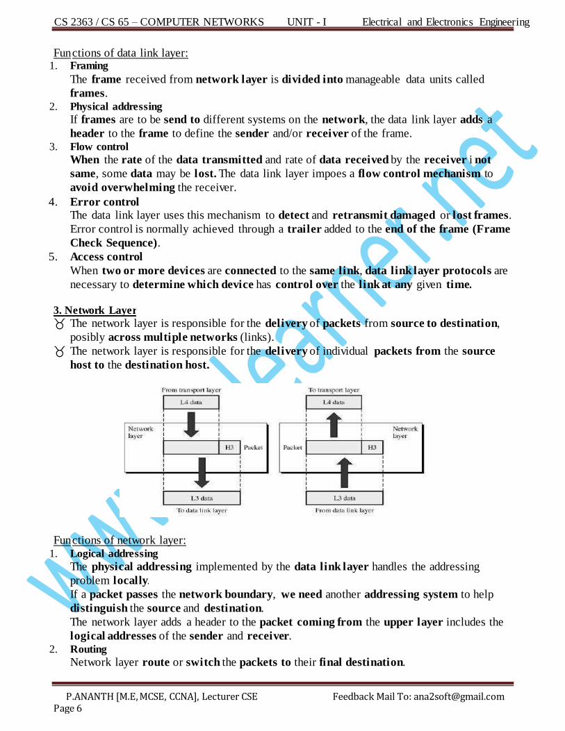
necessary to determine which device has control over the link at any given time. 3. Network Layer
The network layer is responsible for the delivery of packets from source to destination,
posibly across multiple networks (links).
The network layer is responsible for the delivery of individual packets from the source
host to the destination host.
Fun ctions of network layer: 1. Logical addressing
The physical addressing implemented by the data link layer handles the addressing
problem locally.
If a packet passes the network boundary, we need another addressing system to help
distinguish the source and destination.
The network layer adds a header to the packet coming from the upper layer includes the
logical addresses of the sender and receiver. 2. Routing
Network layer route or switch the packets to their final destination.
CS 2363 / CS 65 – COMPUTER NETWORKS UNIT - I Electrical and Electronics Engineering
P.ANANTH [M.E, MCSE, CCNA], Lecturer CSE Feedback Mail To: [email protected] Page 7
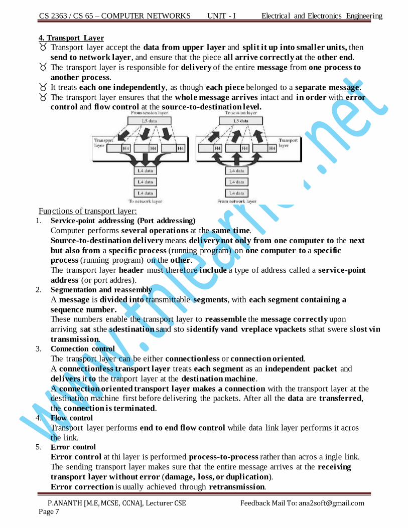
4. Transport Layer Transport layer accept the data from upper layer and split it up into smaller units, then
send to network layer, and ensure that the piece all arrive correctly at the other end. The transport layer is responsible for delivery of the entire message from one process to
another process. It treats each one independently, as though each piece belonged to a separate message. The transport layer ensures that the whole message arrives intact and in order with error
control and flow control at the source-to-destination level.
Fun ctions of transport layer:
1. Service-point addressing (Port addressing)
Computer performs several operations at the same time.
Source-to-destination delivery means delivery not only from one computer to the next
but also from a specific process (running program) on one computer to a specific process (running program) on the other.
The transport layer header must therefore include a type of address called a service-point
address (or port addres). 2. Segmentation and reassembly
A message is divided into transmittable segments, with each segment containing a
sequence number. These numbers enable the transport layer to reassemble the message correctly upon
arriving sat sthe sdestination sand sto sidentify vand vreplace vpackets sthat swere slost vin
transmission. 3. Connection control
The transport layer can be either connectionless or connection oriented.
A connectionless transport layer treats each segment as an independent packet and
delivers it to the tranport layer at the destination machine.
A connection oriented transport layer makes a connection with the transport layer at the destination machine first before delivering the packets. After all the data are transferred,
the connection is terminated. 4. Flow control
Transport layer performs end to end flow control while data link layer performs it acros
the link. 5. E rror control
Error control at thi layer is performed process-to-process rather than acros a ingle link.
The sending transport layer makes sure that the entire message arrives at the receiving
transport layer without error (damage, loss, or duplication).
Error correction is uually achieved through retransmission.
CS 2363 / CS 65 – COMPUTER NETWORKS UNIT - I Electrical and Electronics Engineering
P.ANANTH [M.E, MCSE, CCNA], Lecturer CSE Feedback Mail To: [email protected] Page 8
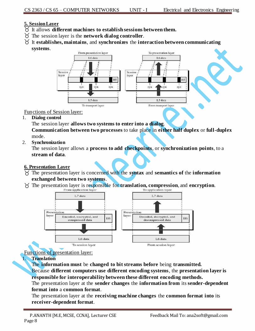
5. Session Layer It allows different machines to establish sessions between them. The session layer is the network dialog controller. It establishes, maintains, and synchronizes the interaction between communicating
systems.
Fun ctions of Session layer:
1. Dialog control
The session layer allows two systems to enter into a dialog.
Communication between two processes to take place in either half duplex or full-duplex
mode. 2. Synchronization
The session layer allows a process to add checkpoints, or synchronization points, to a
stream of data.
6. Presentation Layer
The presentation layer is concerned with the syntax and semantics of the information
exchanged between two systems.
The presentation layer is responsible for translation, compression, and encryption.
Fun ctions of presentation layer:
1. Translation
The information must be changed to bit streams before being transmitted.
Because different computers use different encoding systems , the presentation layer is
responsible for interoperability between these different encoding methods. The presentation layer at the sender changes the information from its sender-dependent
format into a common format.
The presentation layer at the receiving machine changes the common format into its
receiver-dependent format.
CS 2363 / CS 65 – COMPUTER NETWORKS UNIT - I Electrical and Electronics Engineering
P.ANANTH [M.E, MCSE, CCNA], Lecturer CSE Feedback Mail To: [email protected] Page 9
2. E ncryption
To carry sensitive information, a system must be able to ensure privacy.
Encryption means that the sender transforms the original information to another form
and sends the resulting mesage out over the network.
Decryption reverses the original process to transform the message back to its original
form. 3. Compression
Data compresion reduces the number of bits contained in the information.
Data compression becomes particularly important in the transmission of multimedia such
as text, audio, and sideo.
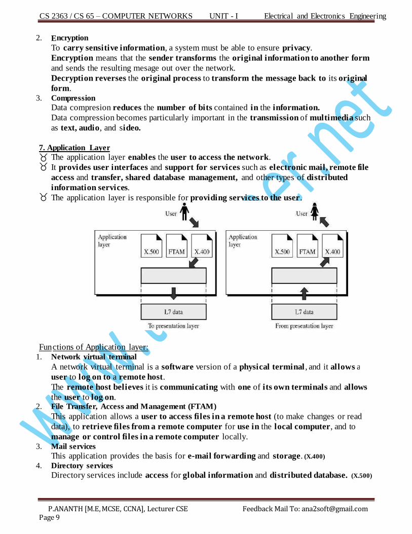
7. Application Layer
The application layer enables the user to access the network. It provides user interfaces and support for services such as electronic mail, remote file
access and transfer, shared database management, and other types of distributed
information services. The application layer is responsible for providing services to the user.
Fun ctions of Application layer: 1. Network virtual terminal
A network virtual terminal is a software version of a physical terminal , and it allows a
user to log on to a remote host.
The remote host believes it is communicating with one of its own terminals and allows
the user to log on. 2. File Transfer, Access and Management (FTAM)
This application allows a user to access files in a remote host (to make changes or read
data), to retrieve files from a remote computer for use in the local computer, and to
manage or control files in a remote computer locally. 3. M ail services
This application provides the basis for e-mail forwarding and storage. (X.400) 4. Directory services
Dir ectory services include access for global information and distributed database. (X.500)
CS 2363 / CS 65 – COMPUTER NETWORKS UNIT - I Electrical and Electronics Engineering
P.ANANTH [M.E, MCSE, CCNA], Lecturer CSE Feedback Mail To: [email protected] Page 10
Summary of Layers
Name the seven layers of the OSI model? (Apr/May’05 – 2mark)
What is the main function of a Physical Layer? (May/Jun’11-2Mark)
What is the prime function of a Physical Layer? (Nov/Dec’04-2Mark)
De fine Packet? (Nov/Dec’11 – 2Mark)
State main function of transport layer? (Apr/May’05 – 2Mark)
G ive two services offered by sesion layer? (Nov/Dec’04 – 2Mark)
CS 2363 / CS 65 – COMPUTER NETWORKS UNIT - I Electrical and Electronics Engineering
P.ANANTH [M.E, MCSE, CCNA], Lecturer CSE Feedback Mail To: [email protected] Page 11
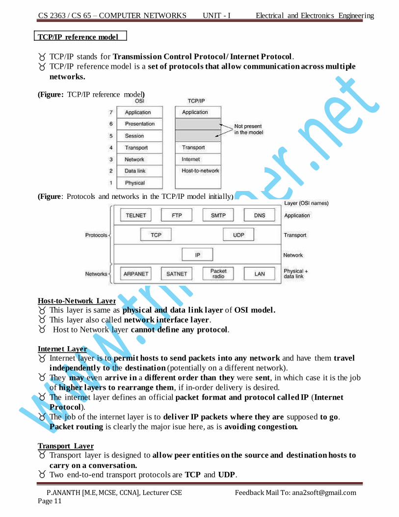
TCP/IP reference model
TCP/IP stands for Transmission Control Protocol/ Internet Protocol.
TCP/IP reference model is a set of protocols that allow communication across multiple
networks. (Figure: TCP/IP reference model)
(Figure: Protocols and networks in the TCP/IP model initially)
Host-to-Network Layer
This layer is same as physical and data link layer of OSI model. This layer also called network interface layer. Host to Network layer cannot define any protocol.
Internet Layer
Internet layer is to permit hosts to send packets into any network and have them travel
independently to the destination (potentially on a different network). They may even arrive in a different order than they were sent, in which case it is the job
of higher layers to rearrange them, if in-order delivery is desired. The internet layer defines an official packet format and protocol called IP (Internet
Protocol). The job of the internet layer is to deliver IP packets where they are supposed to go.
Packet routing is clearly the major isue here, as is avoiding congestion.
Transport Layer Transport layer is designed to allow peer entities on the source and destination hosts to
carry on a conversation. Two end-to-end transport protocols are TCP and UDP.
CS 2363 / CS 65 – COMPUTER NETWORKS UNIT - I Electrical and Electronics Engineering
P.ANANTH [M.E, MCSE, CCNA], Lecturer CSE Feedback Mail To: [email protected] Page 12
TCP (Transmission Control Protocol ) is a reliable connection-oriented protocol that allows a byte stream originating on one machine to be delivered without error on any
other machine in the internet. It fragments the incoming byte stream into discrete
messages and passes each one on to the internet layer. At the destination, the receiving
TCP process reassembles the received messages into the output stream. TCP also
handles flow control to make sure a fast sender cannot swamp a slow receiver with more
mesages than it can handle.
UDP (User Datagram Protocol) i an unreliable, connectionless protocol for applications
that do not want TCP's sequencing or flow control and wish to provide their own. It is
also widely used for one-shot, client-server-type request-reply queries and applications in
which prompt delivery is more important than accurate delivery, such as transmitting
peech or video.
Application Layer
TCP/IP model does not have session or presentation layers.
It contains all the higher-level protocols. The early ones included virtual terminal
(T ELNET), file transfer (FTP), and electronic mail (SMTP). The virtual terminal protocol (TELNET) allows a user on one machine to log onto a
distant machine and work there. The file transfer protocol (FTP) provides a way to move data efficiently from one
machine to another. Electronic mail wa originally jut a kind of file transfer, but later a pecialized protocol
( SM TP) was developed for it. Many other protocols have been added to these over the years: the Domain Name System
(DNS) for mapping host names onto their network addresses , NNTP, the protocol for
moving USENET news articles around, and HTTP, the protocol for fetching pages on
the World Wide Web, and many others.
Perform a comparative study between the ISO/OSI model and TCP/IP reference model? (May/June’12 – 16Mark)
Compare and contrast ISO/OSI and TCP/IP reference models? (Nov/Dec’09 – 8Mark) Perform a comparative study between the ISO OSI model and the TCP/IP reference model? (May/June’07 – 12Mark)
Compare ISO-OSI model and TCP/IP reference model? (May/June’10 – 2Mark)
C omparison of ISO/OSI and TCP/IP reference model TCP/IP tands for Transmission Control Protocol / Internet Protocol .
Layers in the TCP/IP protocol uite do not exactly match thoe in the OSI model.
TCP/IP protocol suite was defined as having four layers: They are,
Host-to-Network, Internet, Transport, Application
When TCP/IP is compared to OSI,
The Host-to-Network layer is equivalent to the combination of the physical and data
link layers. The Internet layer is equivalent to the network layer. The application layer in TCP/IP is equivalent to the session, presentation, application
layer of the OSI reference model.
CS 2363 / CS 65 – COMPUTER NETWORKS UNIT - I Electrical and Electronics Engineering
P.ANANTH [M.E, MCSE, CCNA], Lecturer CSE Feedback Mail To: [email protected] Page 13
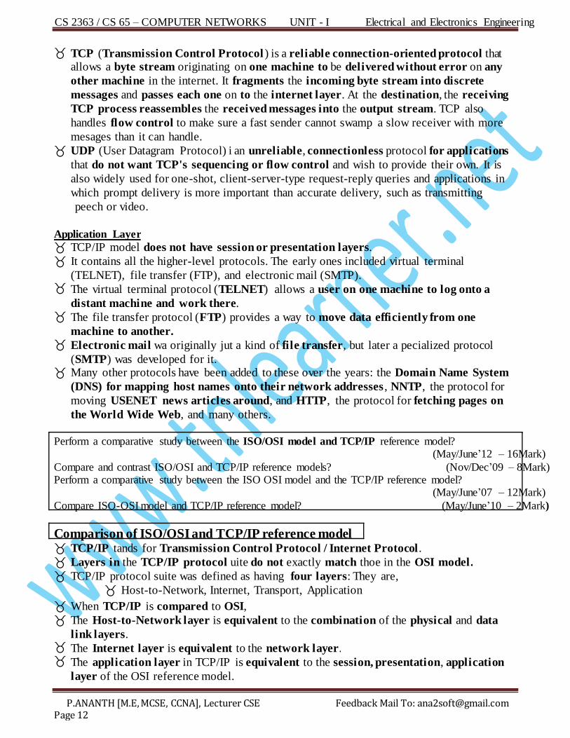
The first four layers provide physical standards, network interfaces, internetworking,
and transport functions that correspond to the first four layers of the OSI model.
The three topmost layers in the OSI model , however, are represented in TCP/IP by a
single layer called the application layer.
The OSI model specifies which functions belong to each of its layers, the layers of the
TCP/IP protocol uite contain relatively independent protocols that can be mixed and
matched depending on the needs of the system.
At the transport layer, TCP/IP defines three protocols: Transmission Control Protocol
(TCP), User Datagram Protocol (UDP), and Stream Control Transmission Protocol
(SCTP). At the network layer, the main protocol defined by TCP/IP is the Internetworking
Protocol (IP).
1. Host to Network (Physical and Data Link Layers)
This layer is same as physical and data link layer of OSI model.
This layer also called network interface layer. Host to Network layer cannot define any protocol.
2. Internet layer (Network Layer)
At the network layer, TCP/IP supports the Internetworking Protocol.
IP, in turn, use four supporting protocols:
o ARP, RARP, ICMP, IGMP. 2.1. Internetworking Protocol (IP)
The Internetworking Protocol (IP) is the transmission mechanism used by the TCP/IP
protocols.
It is an unreliable and connectionless protocol-a best-effort delivery service.
IP transports data in packets called datagrams, each of which i tranported separately.
IP provide the following services,
a. Addressing Determine the Route to deliver data to the detination hot.
b. Fragmentation Breaking the mesages into pieces if an intervening network cannot
handle a large message.
CS 2363 / CS 65 – COMPUTER NETWORKS UNIT - I Electrical and Electronics Engineering
P.ANANTH [M.E, MCSE, CCNA], Lecturer CSE Feedback Mail To: [email protected] Page 14
2.2 Addres Resolution Protocol The Address Resolution Protocol (ARP) is used to associate a logical address with a
physical address. In a LAN each device on a link is identified by a physical or station address, usually
imprinted on the network interface card (NIC). ARP is used to find the physical address of the node when its Internet address is known.
2.3. Reverse Addres Resolution Protocol:
The Reverse Address Resolution Protocol (RARP) allows a host to discover its Internet
address when it knows only its physical address. 2.4. Internet Control Mesage Protocol:
The Internet Control Message Protocol (ICMP) is a mechanism used by hosts and
gateways to send notification of datagram problems back to the sender. ICMP sends query and error reporting messages.
2.5. Internet Group Management Protocol:
The Internet Group Management Protocol (IGMP) is used to facilitate the simultaneous
transmission of a message to a group of recipients.
3. Transport Layer The transport layer was represented in TCP/IP by two protocols:
o TCP , UDP, SCTP IP is a host-to-host protocol , meaning that it can deliver a packet from one physical
device to another. UDP and TCP are tranport level protocol responsible for delivery of a message from a
process (running program) to another process.
SCTP has some newer applications. 3.1. User Datagram Protocol:
UDP is a connection oriented protocol (unreliable)
It is a proces-to-proces protocol that adds only port addresses, checksum error control,
and length information to the data from the upper layer. 3.2. Transmission Control Protocol: TCP provides transport-layer services to applications. TCP is a connection oriented protocol (reliable) transport protocol. Connection-oriented means:
o A connection must be established between both ends of a transmission before either
can transmit data.
o At the sending end of each transmision, TCP divides a stream of data into smaller
units called segments.
o Each segment includes a sequence number for reordering after receipt, together with
an acknowledgment number for the segments received.
o At the receiving end, TCP collects each datagram as it comes in and reorders the
transmission based on sequence numbers.

CS 2363 / CS 65 – COMPUTER NETWORKS UNIT - I Electrical and Electronics Engineering
P.ANANTH [M.E, MCSE, CCNA], Lecturer CSE Feedback Mail To: [email protected] Page 15
3.3. Stream Control Transmission Protocol: The Stream Control Transmission Protocol (SCTP) provides support for newer
applications uch as soice over the Internet. It is a transport layer protocol that combines the best features of UDP and TCP.
4. Application Layer
The application layer in TCP/IP is equivalent to the combined session, presentation, and
application layers in the OSI model
Many protocols are defined at this layer. (TELNET, SMTP, FTP, DNS)
Explain the various factors contributing to the network performance? (Apr/May’11 – 8Mark)
Network Performance
Network performance is measured in two ways: bandwidth (also called throughput)
and latency (also called delay). Bandwidth of a network is given by the number of bits that can be transmitted over the
network in a certain period of time.
Latency correspond to how long it takes a message to travel from one end of a network
to the other. Latency i measured strictly in terms of time. It’ alo called Transit time.
Latency =Propagation + Transmit + Queue Propagation = Distance/Speed of Light Transmit = Size/Bandwidth Distance is the length of the wire, Speed of Light is the effective speed of light over that
wire, Size is the size of the packet, and Bandwidth is the bandwidth at which the packet
is transmitted.
Delay × Bandwidth Product
The latency corresponds to the length of the pipe and the bandwidth gives the diameter of
the pipe, then the delay × bandwidth product gives the volume of the pipe the number of
bits it holds. The delay × bandwidth product is important to know when constructing high performance
networks because it corresponds to how many bits the sender must transmit before the first
bit arrives at the receiver.
Data Representation
Information (Data) represented in different form such as text, numbers, images,
audio, and video.
CS 2363 / CS 65 – COMPUTER NETWORKS UNIT - I Electrical and Electronics Engineering
P.ANANTH [M.E, MCSE, CCNA], Lecturer CSE Feedback Mail To: [email protected] Page 16
Data Flow
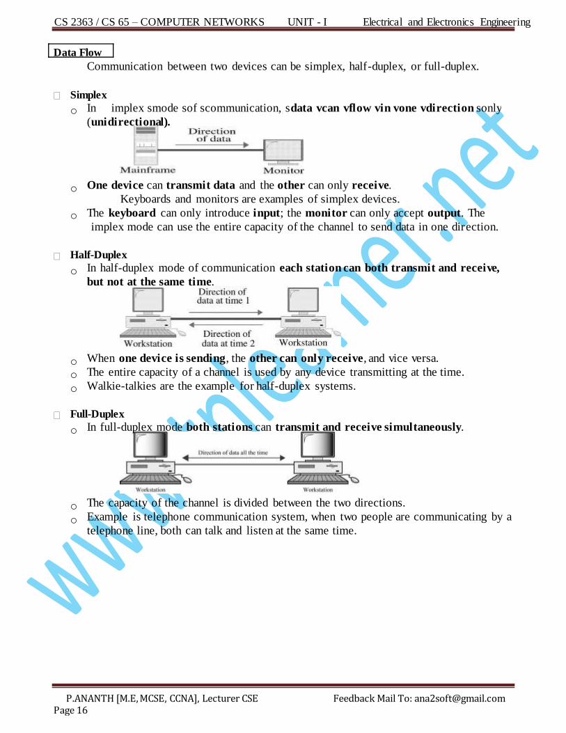
Communication between two devices can be simplex, half-duplex, or full-duplex.
Simplex
o In implex smode sof scommunication, sdata vcan vflow vin vone vdirection sonly
( unidirectional).
o One device can transmit data and the other can only receive.
Keyboards and monitors are examples of simplex devices.
o The keyboard can only introduce input; the monitor can only accept output. The
implex mode can use the entire capacity of the channel to send data in one direction.
Half-Duplex
o In half-duplex mode of communication each station can both transmit and receive,
but not at the same time.
o When one device is sending, the other can only receive, and vice versa.
o The entire capacity of a channel is used by any device transmitting at the time.
o Walkie-talkies are the example for half-duplex systems.
Full-Duplex
o In full-duplex mode both stations can transmit and receive simultaneously.
o The capacity of the channel is divided between the two directions.
o Example is telephone communication system, when two people are communicating by a
telephone line, both can talk and listen at the same time.
CS 2363 / CS 65 – COMPUTER NETWORKS UNIT - I Electrical and Electronics Engineering
P.ANANTH [M.E, MCSE, CCNA], Lecturer CSE Feedback Mail To: [email protected] Page 17
Di tinguish between point-to-point links and multi-point links with relevant diagram? s
(May/June’12 – 16Mark)
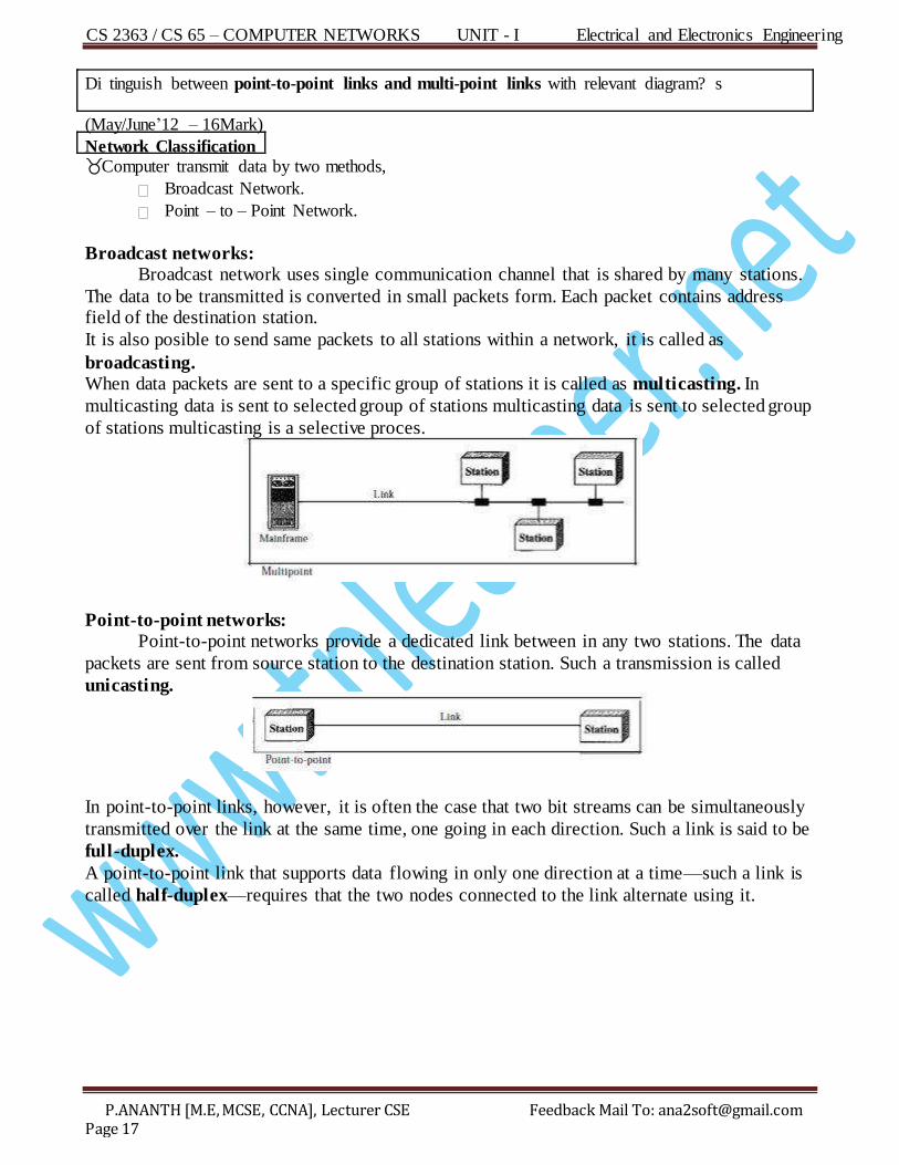
Network Classification Computer transmit data by two methods,
Broadcast Network.
Point – to – Point Network.
Broadcast networks: Broadcast network uses single communication channel that is shared by many stations.
The data to be transmitted is converted in small packets form. Each packet contains address field of the destination station.
It is also posible to send same packets to all stations within a network, it is called as
broadcasting. When data packets are sent to a specific group of stations it is called as multicasting. In
multicasting data is sent to selected group of stations multicasting data is sent to selected group
of stations multicasting is a selective proces.
Point-to-point networks: Point-to-point networks provide a dedicated link between in any two stations. The data
packets are sent from source station to the destination station. Such a transmission is called
unicasting.
In point-to-point links, however, it is often the case that two bit streams can be simultaneously
transmitted over the link at the same time, one going in each direction. Such a link is said to be
full-duplex.
A point-to-point link that supports data flowing in only one direction at a time—such a link is
called half-duplex—requires that the two nodes connected to the link alternate using it.
CS 2363 / CS 65 – COMPUTER NETWORKS UNIT - I Electrical and Electronics Engineering
P.ANANTH [M.E, MCSE, CCNA], Lecturer CSE Feedback Mail To: [email protected] Page 18
Write the categories of networks? s (Apr/May’11 – 2Mark) What are LAN? (Apr/May’05 – 2mark)
Categories of Networks Local Area Network (LAN) Wide Area Network (WAN) Metropolitan Area Network (MAN)
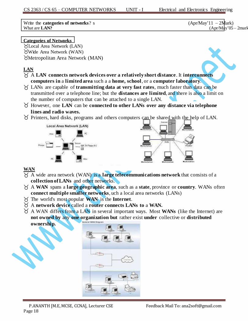
LAN
A LAN connects network devices over a relatively short distance . It interconnects
computers in a limited area such a a home, school , or a computer laboratory.
LANs are capable of transmitting data at very fast rates, much faster than data can be
transmitted over a telephone line; but the distances are limited, and there is also a limit on
the number of computers that can be attached to a single LAN. However, one LAN can be connected to other LANs over any distance via telephone
lines and radio waves. Printers, hard disks, programs and others computers can be shared with the help of LAN.
WAN
A wide area network (WAN) is a large telecommunications network that consists of a
collection of LANs and other networks.
A WAN spans a large geographic area, such as a state, province or country. WANs often
connect multiple smaller networks, uch a local area networks (LANs)
The world's most popular WAN is the Internet. A network device called a router connects LANs to a WAN. A WAN differs from a LAN in several important ways. Most WANs (like the Internet) are
not owned by any one organization but rather exist under collective or distributed
ownership.
CS 2363 / CS 65 – COMPUTER NETWORKS UNIT - I Electrical and Electronics Engineering
P.ANANTH [M.E, MCSE, CCNA], Lecturer CSE Feedback Mail To: [email protected] Page 19
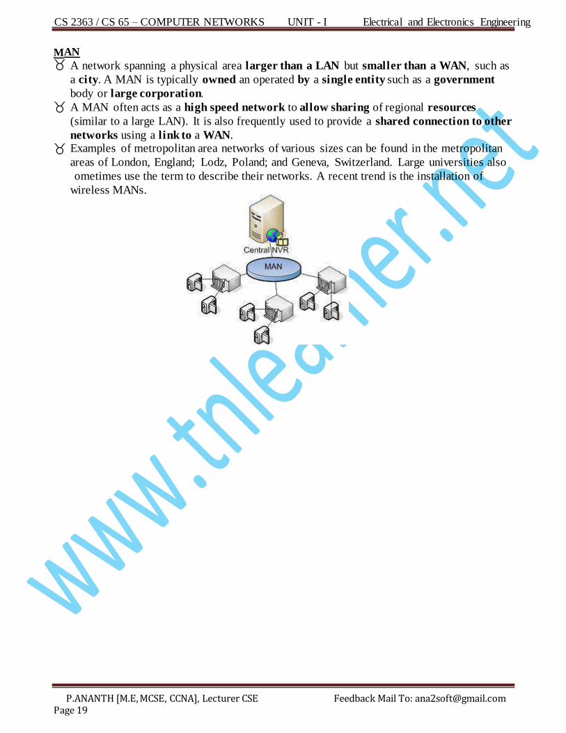
M AN A network spanning a physical area larger than a LAN but smaller than a WAN, such as
a city. A MAN is typically owned an operated by a single entity such as a government
body or large corporation. A MAN often acts as a high speed network to allow sharing of regional resources
(si milar to a large LAN). It is also frequently used to provide a shared connection to other
networks using a link to a WAN. Examples of metropolitan area networks of various sizes can be found in the metropolitan
areas of London, England; Lodz, Poland; and Geneva, Switzerland. Large universities also
ometimes use the term to describe their networks. A recent trend is the installation of
wireless MANs.
CS 2363 / CS 65 – COMPUTER NETWORKS UNIT - I Electrical and Electronics Engineering
P.ANANTH [M.E, MCSE, CCNA], Lecturer CSE Feedback Mail To: [email protected] Page 20
Di cuss the four basic network topologies and give the advantages and disadvantages of each type? (Apr/May’11 – 8Mark)
List out the four basic topologies? s (Apr/May’11 – 2Mark)
What are the different network topologies to organize computer networks? (Nov/Dec’04 – 2Mark)
Network Topologies The sterm sphysical vtopology refers sto sthe sway vin vwhich va vnetwork vis vphysically
interconnected. Two or more devices connect to a link; two or more links form a topology. The network topology is the geometric representation of the relationship of all the links
(m edium) and linking devices (nodes) to one another.
There are four basic topologies possible: Mesh, Star, Bus, and Ring.
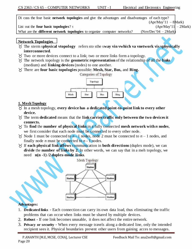
1. Mesh Topology
In a mesh topology, every device has a dedicated point-to-point link to every other
device. The term dedicated means that the link carries traffic only between the two devices it
connects. To find the number of physical links in a fully connected mesh network with n nodes,
we first consider that each node must be connected to every other node.
Node 1 must be connected to n - 1 nodes, node 2 must be connected to n – 1 nodes, and
finally node n must be connected to n - 1 nodes.
If each physical link allows communication in both directions (duplex mode), we can
divide the number of links by 2. In other words, we can say that in a meh topology, we
need n(n -1) /2 duplex-mode links.
Advantages:
1. Dedicated links - Each connection can carry its own data load, thus eliminating the traffic
problems that can occur when links must be shared by multiple devices.
2. Robust - If one link becomes unusable, it does not affect the entire network.
3. Privacy or security - When every message travels along a dedicated line, only the intended recipient sees it. Physical boundaries prevent other users from gaining acces to messages.
CS 2363 / CS 65 – COMPUTER NETWORKS UNIT - I Electrical and Electronics Engineering
P.ANANTH [M.E, MCSE, CCNA], Lecturer CSE Feedback Mail To: [email protected] Page 21
4. E asy fault identification and fault isolation - Point-to-point links between the nodes, so fault
identification and fault isolation easy. Disadvantages:
1 . Difficulty in installation and reconfiguration - Every device must be connected to every other device so installation and reconnection are difficult.
2. M ore Expensive - The hardware required to connect each link (I/O ports and cable) can be prohibitively expensive.
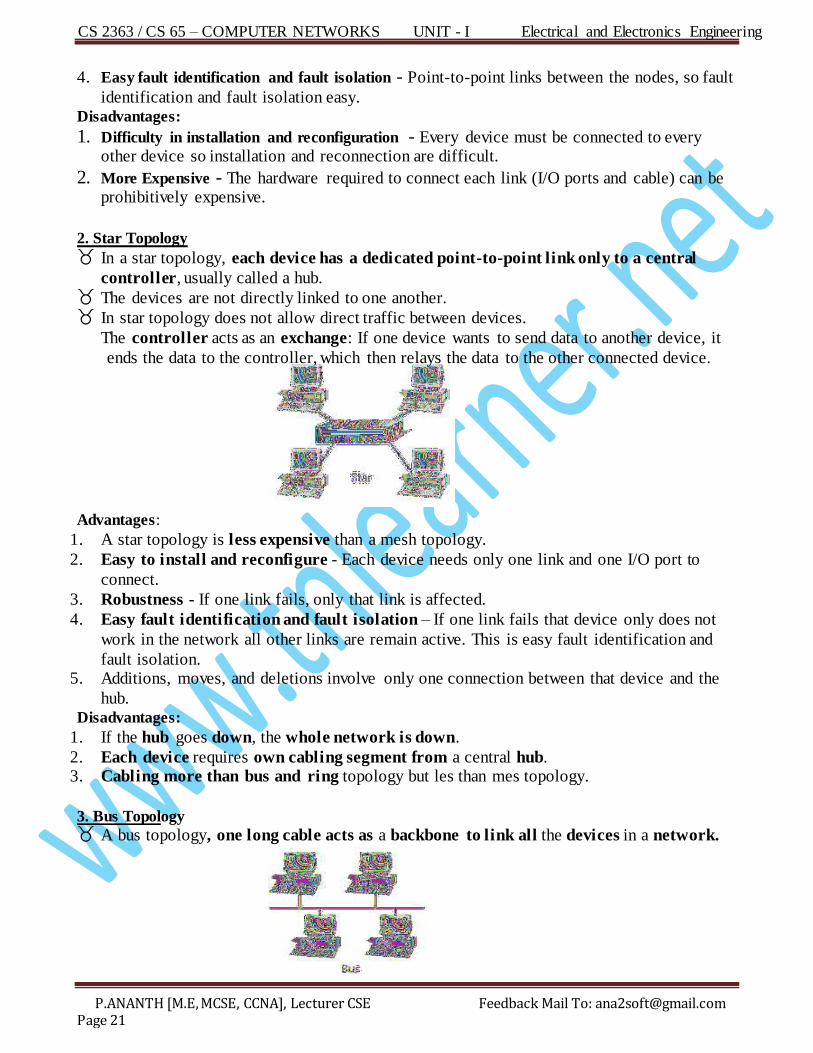
2. Star Topology In a star topology, each device has a dedicated point-to-point link only to a central
controller, usually called a hub. The devices are not directly linked to one another. In star topology does not allow direct traffic between devices.
The controller acts as an exchange: If one device wants to send data to another device, it
ends the data to the controller, which then relays the data to the other connected device.
Advantages:
1 . A star topology is less expensive than a mesh topology.
2. Easy to install and reconfigure - Each device needs only one link and one I/O port to
connect.
3. Robustness - If one link fails, only that link is affected.
4 . Easy fault identification and fault isolation – If one link fails that device only does not
work in the network all other links are remain active. This is easy fault identification and
fault isolation. 5. Additions, moves, and deletions involve only one connection between that device and the
hub. Disadvantages:
1 . If the hub goes down, the whole network is down.
2. Each device requires own cabling segment from a central hub. 3. Cabling more than bus and ring topology but les than mes topology.
3. Bus Topology A bus topology, one long cable acts as a backbone to link all the devices in a network.
CS 2363 / CS 65 – COMPUTER NETWORKS UNIT - I Electrical and Electronics Engineering
P.ANANTH [M.E, MCSE, CCNA], Lecturer CSE Feedback Mail To: [email protected] Page 22
Nodes are connected to the bu cable by drop lines and taps. A drop line is a connection running between the device and the main cable.
A tap is a connector that splices the main cable to create a contact with the metallic
core.
Advantages:
1. Easy to installation.
2. Needs fewer connectivity devices.
3. Low cost.
4. Bus topology uses less cabling than mesh and star topologies. Disadvantages:
1. Difficult to add new devices.
2. Signal reflection at the taps can cause degradation in quality.
3. Heavy network traffic can slow a performance.
4. Difficult reconnection and fault isolation.
5. In addition, a fault or break in the bus cable stops all transmission, even between
devices on the same side of the problem. .
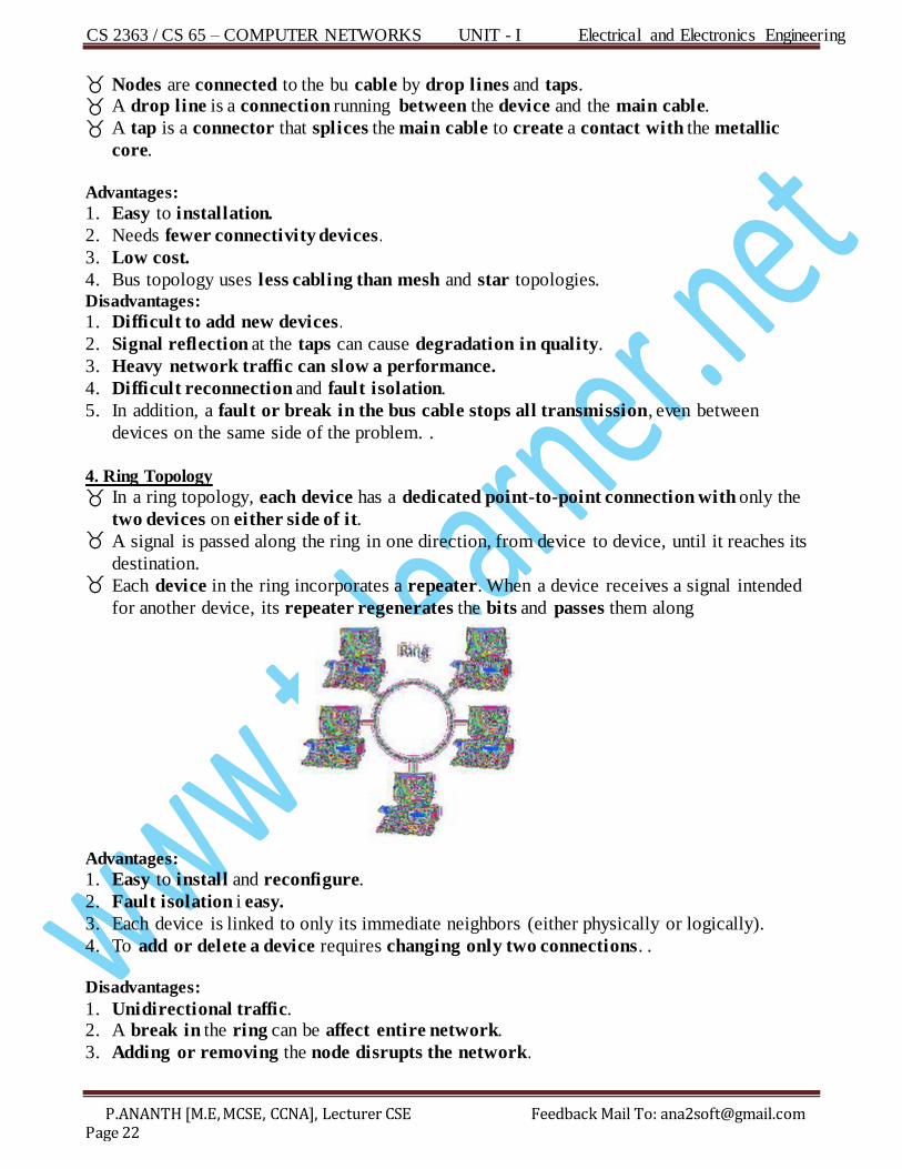
4. Ring Topology
In a ring topology, each device has a dedicated point-to-point connection with only the
two devices on either side of it. A signal is passed along the ring in one direction, from device to device, until it reaches its
destination. Each device in the ring incorporates a repeater. When a device receives a signal intended
for another device, its repeater regenerates the bits and passes them along
Advantages:
1. Easy to install and reconfigure.
2. Fault isolation i easy.
3. Each device is linked to only its immediate neighbors (either physically or logically).
4. To add or delete a device requires changing only two connections. . Disadvantages:
1. Unidirectional traffic. 2. A break in the ring can be affect entire network.
3. Adding or removing the node disrupts the network.
CS 2363 / CS 65 – COMPUTER NETWORKS UNIT - I Electrical and Electronics Engineering
P.ANANTH [M.E, MCSE, CCNA], Lecturer CSE Feedback Mail To: [email protected] Page 23
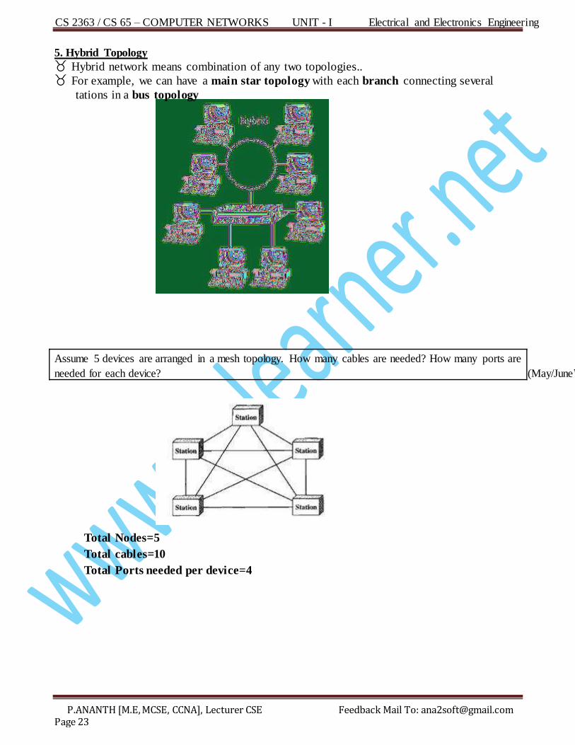
5. Hybrid Topology H ybrid network means combination of any two topologies.. For example, we can have a main star topology with each branch connecting several
tations in a bus topology
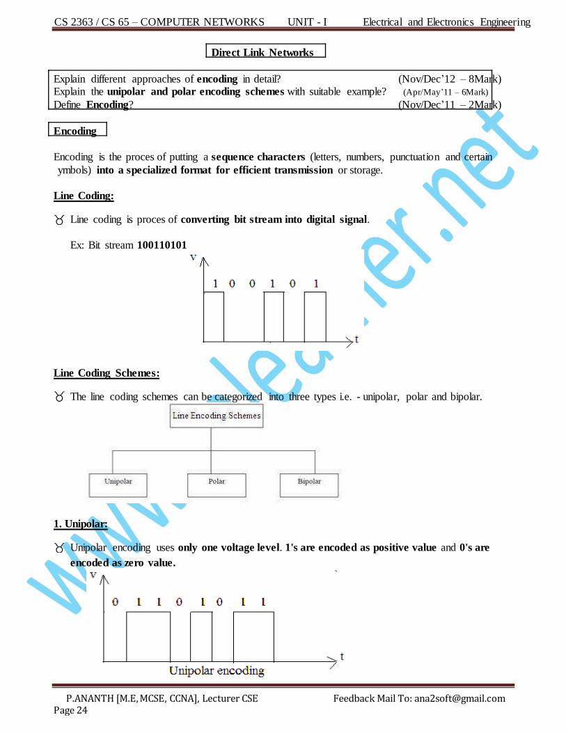
Assume 5 devices are arranged in a mesh topology. How many cables are needed? How many ports are
needed for each device? (May/June’10 – 2Mark)
Total Nodes=5
Total cables=10
Total Ports needed per device=4
CS 2363 / CS 65 – COMPUTER NETWORKS UNIT - I Electrical and Electronics Engineering
P.ANANTH [M.E, MCSE, CCNA], Lecturer CSE Feedback Mail To: [email protected] Page 24
D irect Link Networks
Explain different approaches of encoding in detail? (Nov/Dec’12 – 8Mark) Explain the unipolar and polar encoding schemes with suitable example? (Apr/May’11 – 6Mark)
De fine Encoding? (Nov/Dec’11 – 2Mark)
E ncoding
Encoding is the proces of putting a sequence characters (letters, numbers, punctuation and certain
ymbols) into a specialized format for efficient transmission or storage.
Line Coding:
Line coding is proces of converting bit stream into digital signal.
Ex: Bit stream 100110101
Line Coding Schemes:
The line coding schemes can be categorized into three types i.e. - unipolar, polar and bipolar.
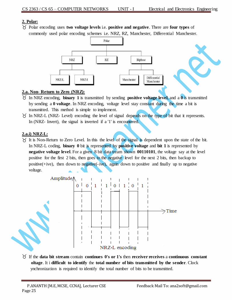
1. Unipolar:
Unipolar encoding uses only one voltage level. 1's are encoded as positive value and 0's are
encoded as zero value.
CS 2363 / CS 65 – COMPUTER NETWORKS UNIT - I Electrical and Electronics Engineering
P.ANANTH [M.E, MCSE, CCNA], Lecturer CSE Feedback Mail To: [email protected] Page 25
2. Polar:
Polar encoding uses two voltage levels i.e. positive and negative. There are four types of
commonly used polar encoding schemes i.e. NRZ, RZ, Manchester, Differential Manchester.
2.a. Non- Return to Zero (NRZ):
In NRZ encoding, binary 1 is transmitted by sending positive voltage level, and a 0 is transmitted
b y sending a 0 voltage. In NRZ encoding, voltage level stay constant during the time a bit is
transmitted. This method is simple to implement.
In NRZ-L (NRZ- Level) encoding the level of signal depends on the type of bit that it represents.
In (NRZ- Invert), the signal is inverted if a '1' is encountered.
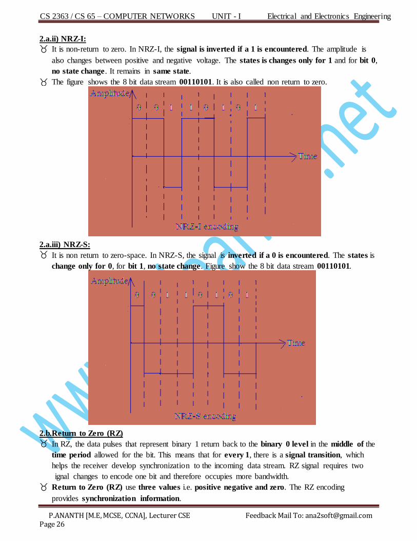
2.a.i) NRZ-L:
It is Non-Return to Zero Level. In this the level of the signal is dependent upon the state of the bit.
In NRZ-L coding, binary 0 bit is represented by positive voltage and bit 1 is represented by
negative voltage level. For a given 8 bit data tream shown 00110101, the voltage say at the level
positive for the first 2 bits, then goes to the negative level for the next 2 bits, then backup to
positive(+ive), then down to negative(- ive), again down to positive and finally up to negative
voltage.
If the data bit stream contain continues 0's or 1's then receiver receives a continuous constant
oltage. It i difficult to identify the total number of bits transmitted by the sender. Clock
ynchronization is required to identify the total number of bits to be transmitted.
CS 2363 / CS 65 – COMPUTER NETWORKS UNIT - I Electrical and Electronics Engineering
P.ANANTH [M.E, MCSE, CCNA], Lecturer CSE Feedback Mail To: [email protected] Page 26
2.a.ii) NRZ-I:
It is non-return to zero. In NRZ-I, the signal is inverted if a 1 is encountered. The amplitude is
also changes between positive and negative voltage. The states is changes only for 1 and for bit 0,
no state change. It remains in same state.
The figure shows the 8 bit data stream 00110101. It is also called non return to zero.
2.a.iii) NRZ-S:
It is non return to zero-space. In NRZ-S, the signal is inverted if a 0 is encountered. The states is
change only for 0, for bit 1, no state change. Figure show the 8 bit data stream 00110101.
2.b.Return to Zero (RZ)
In RZ, the data pulses that represent binary 1 return back to the binary 0 level in the middle of the
time period allowed for the bit. This means that for every 1, there is a signal transition, which
helps the receiver develop synchronization to the incoming data stream. RZ signal requires two
ignal changes to encode one bit and therefore occupies more bandwidth.
Return to Zero (RZ) use three values i.e. positive negative and zero. The RZ encoding
provides synchronization information.
CS 2363 / CS 65 – COMPUTER NETWORKS UNIT - I Electrical and Electronics Engineering
P.ANANTH [M.E, MCSE, CCNA], Lecturer CSE Feedback Mail To: [email protected] Page 27
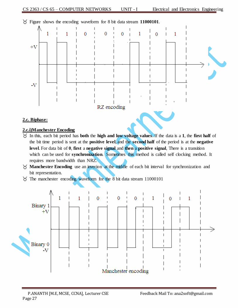
F igure shows the encoding waveform for 8 bit data stream 11000101.
2.c. Biphase:
2.c.i)Manchester Encoding
In this, each bit period has both the high and low voltage values. If the data is a 1, the first half of
the bit time period is sent at the positive level, and the second half of the period is at the negative
level. For data bit of 0, first a negative signal and then a positive signal, There is a transition
which can be used for synchronization. Sometimes this method is called self clocking method. It
requires more bandwidth than NRZ.
M anchester Encoding use an inverion at the middle of each bit interval for synchronization and
bit representation.
The manchester encoding waveform for the 8 bit data stream 11000101
CS 2363 / CS 65 – COMPUTER NETWORKS UNIT - I Electrical and Electronics Engineering
P.ANANTH [M.E, MCSE, CCNA], Lecturer CSE Feedback Mail To: [email protected] Page 28
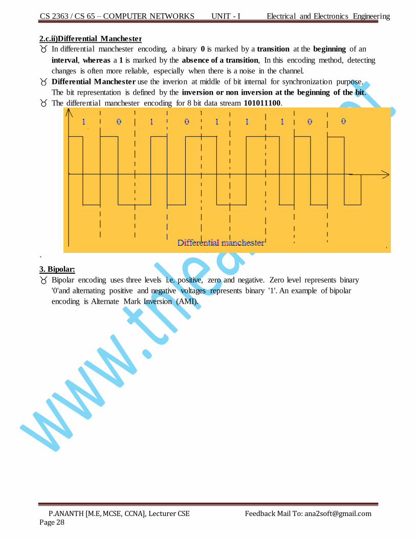
2.c.ii)Differential Manchester
In differential manchester encoding, a binary 0 is marked by a transition at the beginning of an
interval, whereas a 1 is marked by the absence of a transition, In this encoding method, detecting
changes is often more reliable, especially when there is a noise in the channel.
Differential Manchester use the inverion at middle of bit internal for synchronization purpose.
The bit representation is defined by the inversion or non inversion at the beginning of the bit.
The differential manchester encoding for 8 bit data stream 101011100.
`
3. Bipolar:
Bipolar encoding uses three levels i.e. positive, zero and negative. Zero level represents binary
'0'and alternating positive and negative voltages represents binary '1'. An example of bipolar
encoding is Alternate Mark Inversion (AMI).
CS 2363 / CS 65 – COMPUTER NETWORKS UNIT - I Electrical and Electronics Engineering
P.ANANTH [M.E, MCSE, CCNA], Lecturer CSE Feedback Mail To: [email protected] Page 29
De fine Framing? (May/June’12 – 2Mark)
Framing
Encapsulates datagram into frame, adding header and trailer.
Physical address used in frame headers to identify source and destination.
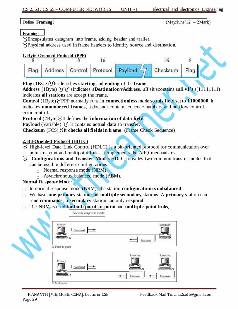
1. Byte-Oriented Protocol (PPP)
Flag (1Byte) It identifies starting and ending of the frame. Address (1Byte) sIndicates sDestination vAddress. sIf sit scontains sall v1’s s(11111111)
indicates all stations are accept the frame.
Control (1Byte) PPP normally runs in connectionless mode so this field set to 11000000. It
indicates unnumbered frames, it doesnot contain sequence numbers and no flow control,
error control.
Protocol (2Byte) It defines the information of data field.
Payload (Variable) It contains actual data to transfer.
Checksum (FCS) It checks all fields in frame. (Frame Check Sequence)
2. Bit-Oriented Protocol (HDLC) High-level Data Link Control (HDLC) is a bit-oriented protocol for communication over
point-to-point and multipoint links. It implements the ARQ mechanisms. Configurations and Transfer Modes HDLC provides two common transfer modes that
can be used in different configurations:
o Normal response mode (NRM)
o Asynchronous balanced mode (ABM).
Normal Response Mode:
In normal response mode (NRM), the station configuration is unbalanced.
We have one primary station and multiple secondary stations. A primary vtation can
end commands; a secondary station can only respond.
The NRM is used for both point-to-point and multiple-point links,
CS 2363 / CS 65 – COMPUTER NETWORKS UNIT - I Electrical and Electronics Engineering
P.ANANTH [M.E, MCSE, CCNA], Lecturer CSE Feedback Mail To: [email protected] Page 30
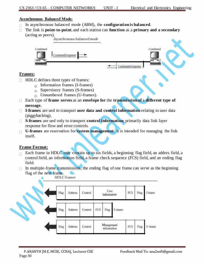
Asynchronous Balanced Mode:
In asynchronous balanced mode (ABM), the configuration is balanced.
The link is point-to-point, and each station can function as a primary and a secondary
(a cting as peers).
Frames:
HDL C defines three types of frames:
o Information frames (I-frames)
o Supervisory frames (S-frames)
o Unnumbered frames (U-frames).
Each type of frame serves as an envelope for the transmission of a different type of
message.
I-frames are ued to transport user data and control information relating to user data
(piggybacking).
S-frames are ued only to transport control information, primarily data link layer
response for flow and error controls.
U-frames are reservation for system management. It is intended for managing the link
itself.
Frame Format:
Each frame in HDLC may contain up to six fields, a beginning flag field, an addres field, a
control field, an information field, a frame check sequence (FCS) field, and an ending flag
field.
In multiple-frame transmissions, the ending flag of one frame can serve as the beginning
flag of the next frame.
CS 2363 / CS 65 – COMPUTER NETWORKS UNIT - I Electrical and Electronics Engineering
P.ANANTH [M.E, MCSE, CCNA], Lecturer CSE Feedback Mail To: [email protected] Page 31
Flag field.
o The flag field of an HDLC frame is an 8-bit sequence with the bit pattern 01111110 that
identifies both the beginning and the end of a frame and serves as a synchronization
pattern for the receiver.
Address field.
o The second field of an HDLC frame contains the address of the secondary station. If a
primary station created the frame, it contains a to address.
o If a secondary creates the frame, it contains a from address.
Control field.
o The control field is a 1 or 2-byte segment of the frame used for flow and error control.
o The interpretation of bits in this field depends on the frame type.
Information field.
o The information field contains the user's data from the network layer or management
information. Its length can sary from one network to another.
FCS field.
o The frame check sequence (FCS) is the HDLC error detection field. It can contain
either a 2- or 4-byte ITU-T CRC.
A network with bandwidth of 10Mbps can pas only an average of 12,000 frames per minute with each frame carrying an average of 10,000 bits. What is the throughput of this network?
(Apr/May’11 – 2Mark) Throughput= (12000 * 10000) / 60 = 120000000 / 60
= 2000000 = 2 Mbps (It is 1/5 of bandwidth)
CS 2363 / CS 65 – COMPUTER NETWORKS UNIT - I Electrical and Electronics Engineering
P.ANANTH [M.E, MCSE, CCNA], Lecturer CSE Feedback Mail To: [email protected] Page 32
What is error detection? Explain with example? (Nov/Dec’11 – 8Mark)
E rror Detection
Process of checking the data unit for the presence of any error. It is simpler than error
correction and it is the first step in error correction process.
Redundancy:
Error detection uses the concept of redundancy, which means adding error bits for
detecting errors at the destination.
4 types of redundancy checks,
VRC
LRC
CRC
Checksum VRC:
It’s a parity check. If the total number of 1’s become even called even parity check.
Similarly total number of 1’s becomes odd called odd parity check.
ie) even no 0
odd no 1
11 10111 11 01111 11 10010 11 01100 11 00100
W s o s r s l d
Ans: s11101110 11 011110 11 100100 11 01100 11 00100
The receiver counts the 1’s and (6, 6, 4, 4, 4) the data would be accepted. If any error
occur, the receiver knows that the data are
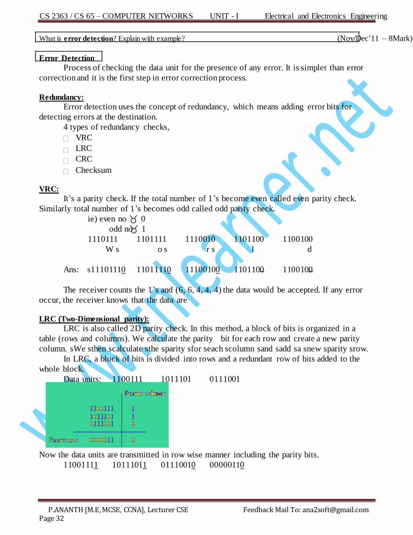
LRC (Two-Dimensional parity):
LRC is also called 2D parity check. In this method, a block of bits is organized in a
table (rows and columns). We calculate the parity bit for each row and create a new parity
column. sWe sthen scalculate sthe sparity sfor seach scolumn sand sadd sa snew sparity srow.
In LRC, a block of bits is divided into rows and a redundant row of bits added to the
whole block.
Data units: 1100111 1011101 0111001
Now the data units are transmitted in row wise manner including the parity bits.
11 001111 10111011 01110010 00000110
CS 2363 / CS 65 – COMPUTER NETWORKS UNIT - I Electrical and Electronics Engineering
P.ANANTH [M.E, MCSE, CCNA], Lecturer CSE Feedback Mail To: [email protected] Page 33
Internet checksum Algorithm:
In the internet checksum just add up all the words that are transmitted and then transmit
the result of that sum. The result is called the checksum. The receiver perform the same
calculation on the received data and compares the result with the received checksum.
If any transmitted data, including the checksum itself, is corrupted, then the results will
not match, so the receiver knows that an error occurred.
Before transmitting the data the sender follows the step,
The unit is divided into ‘K’ sections, each of ‘n’ bits.
All sections are added together using 1’s complement.
The sum is complemented and becomes the checksum.
The checksum is sent along with the data.
After receiving the data,
The unit is divided into k sections, each of ‘n’ bits.
All sections are added together using 1’s complement to get the sum
The sum is completed. If the result is ‘0’, the data is accepted or rejected.
Eg) 16bit 1 0 1 0 1 0 0 1 0 0 1 1 1 0 0 1
1 1 1 0 0 0 1 0
0 0 0 1 1 1 0 1 1’s complement.
The pattern sent is 10101001 00111001 00011101.
Cyclic Redundancy check: (CRC):
In this method, a sequence of redundant bits called CRC. Is appended to the end of the
data unit. So that the resulting data unit becomes exactly divisible by a predetermined binary
number.
At the receiver side the incoming data unit is divided by the same number and if there is
no reminder and the data unit is assumed to be error free and therefore accepted, A reminder
indicates that the data unit has been damaged in transit and therefore must be rejected.
The mesage is represented by the polynomial by using the value of each bit in the
mesage as the co-efficient for each term in the polynomial, starting with the most significant
bit to represent the highest order term.
Eg) 8-bit message bit 10011010 – corresponds to the polynomial, M( x) = 1*xs+0*xs+0*xs+1*xs+1*xs+0*xs+1*xs+0*xs
7 6 5 4 3 2 1 0
For the purpose of calculating a CRC, a sender and receiver have to agree on a divisor
polynomial C(x). C(x) is a polynomial of degree ‘k’.
Eg) C(x) = xs+xs+1 3 2
Where k = 3
When a sender wishes to transmit a message M(x) that is n+1 bits long, it sent (n+1)
mesage plus k bits. We call the complete transmitted message including the redundant bits
P(x).
CS 2363 / CS 65 – COMPUTER NETWORKS UNIT - I Electrical and Electronics Engineering
P.ANANTH [M.E, MCSE, CCNA], Lecturer CSE Feedback Mail To: [email protected] Page 34
If M(x) is exactly divisible by C(x) Multiply M(x) by xs, ie, add k zeros at the end of the mesage.
k
Divide T(x) by C(x) and find the reminder.
Subtract the reminder from T(x).
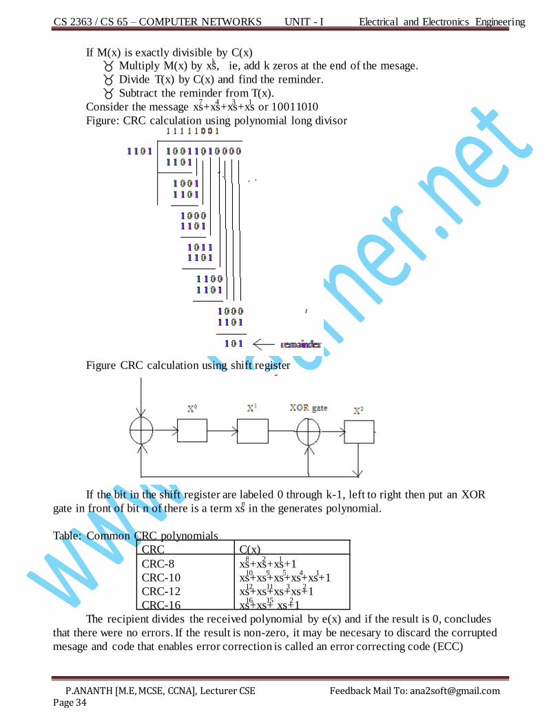
Consider the message xs+xs+xs+xs or 10011010 7 4 3 1
Figure: CRC calculation using polynomial long divisor
Figure CRC calculation using shift register
If the bit in the shift register are labeled 0 through k-1, left to right then put an XOR
gate in front of bit n of there is a term xs in the generates polynomial. n
Table: Common CRC polynomials
CRC C(x)
CRC-8
CRC-10
CRC-12
CRC-16
xs+xs+xs+1 8 2 1
xs+xs+xs+xs+xs+1 1 0 9 5 4 1
xs+xs+xs+xs+1 1 2 1 1 3 2
xs+xs+ xs+1 1 6 1 5 2
The recipient divides the received polynomial by e(x) and if the result is 0, concludes
that there were no errors. If the result is non-zero, it may be necesary to discard the corrupted
mesage and code that enables error correction is called an error correcting code (ECC)
CS 2363 / CS 65 – COMPUTER NETWORKS UNIT - I Electrical and Electronics Engineering
P.ANANTH [M.E, MCSE, CCNA], Lecturer CSE Feedback Mail To: [email protected] Page 35
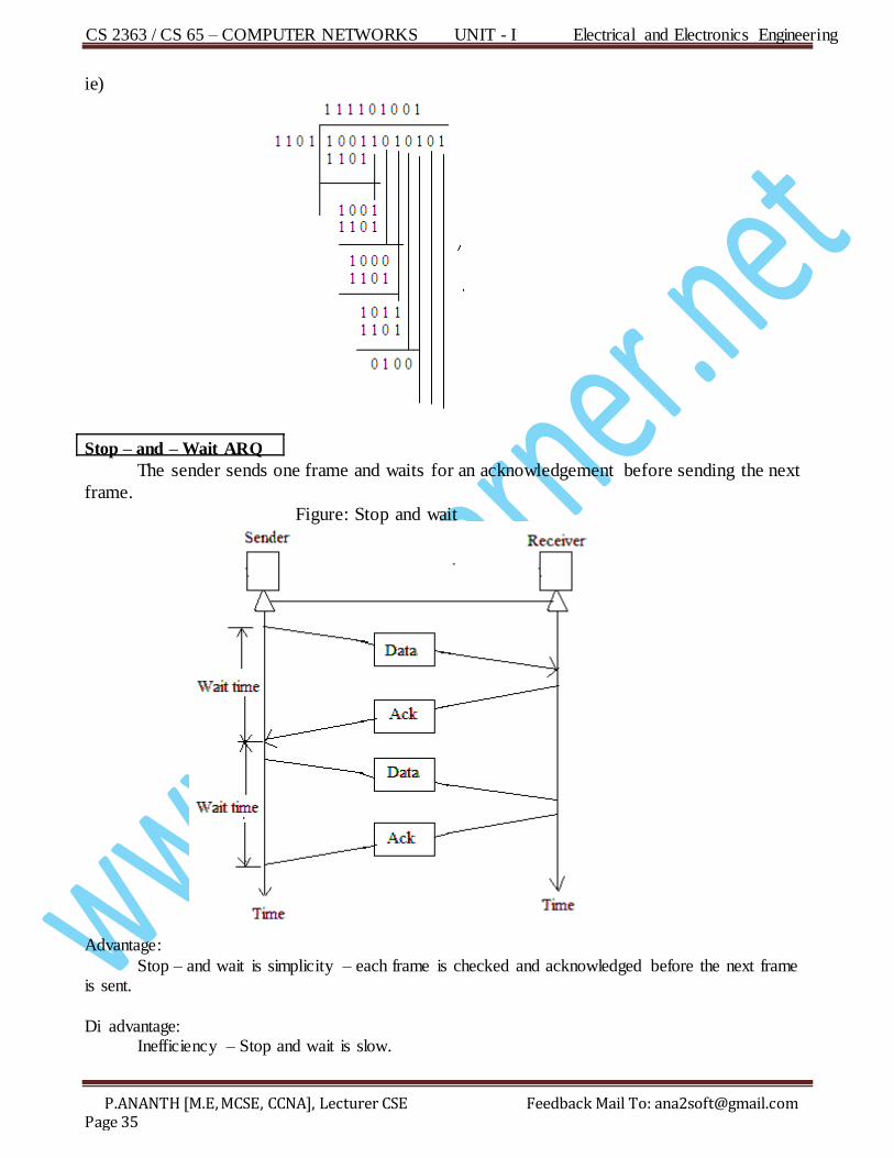
ie)
Stop – and – Wait ARQ
The sender sends one frame and waits for an acknowledgement before sending the next
frame.
Figure: Stop and wait
Advantage:
Stop – and wait is simplicity – each frame is checked and acknowledged before the next frame is sent.
Di advantage: Inefficiency – Stop and wait is slow.
CS 2363 / CS 65 – COMPUTER NETWORKS UNIT - I Electrical and Electronics Engineering
P.ANANTH [M.E, MCSE, CCNA], Lecturer CSE Feedback Mail To: [email protected] Page 36
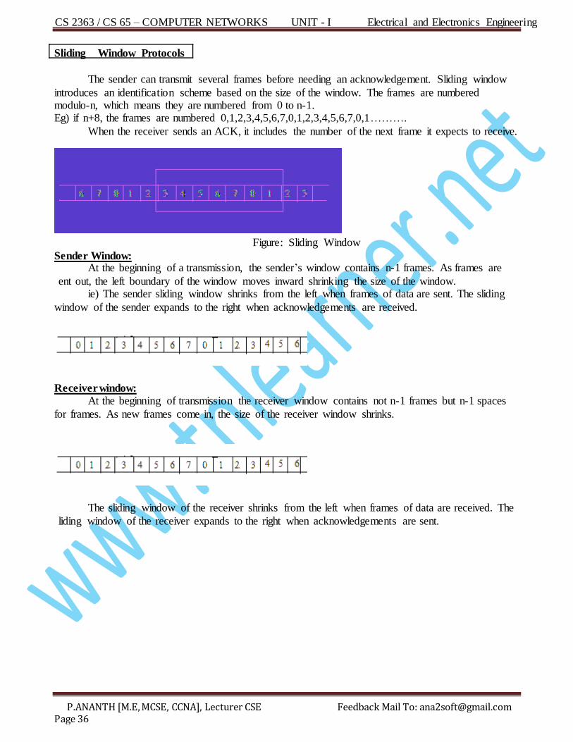
Sliding Window Protocols
The sender can transmit several frames before needing an acknowledgement. Sliding window
introduces an identification scheme based on the size of the window. The frames are numbered modulo-n, which means they are numbered from 0 to n-1. Eg) if n+8, the frames are numbered 0,1,2,3,4,5,6,7,0,1,2,3,4,5,6,7,0,1……….
When the receiver sends an ACK, it includes the number of the next frame it expects to receive.
Figure: Sliding Window
Sender Window: At the beginning of a transmission, the sender’s window contains n-1 frames. As frames are
ent out, the left boundary of the window moves inward shrinking the size of the window. ie) The sender sliding window shrinks from the left when frames of data are sent. The sliding
window of the sender expands to the right when acknowledgements are received.
Receiver window: At the beginning of transmission the receiver window contains not n-1 frames but n-1 spaces
for frames. As new frames come in, the size of the receiver window shrinks.
The sliding window of the receiver shrinks from the left when frames of data are received. The
liding window of the receiver expands to the right when acknowledgements are sent.
CS 2363 / CS 65 – COMPUTER NETWORKS UNIT - I Electrical and Electronics Engineering
P.ANANTH [M.E, MCSE, CCNA], Lecturer CSE Feedback Mail To: [email protected] Page 37
What is Ethernet? Explain in detail? (Nov/Dec’11 – 8Mark) Explain the IEEE 802.3 standard? s (Nov/Dec’12 – 8Mark)
E thernet It is the name of a packet – switching LAN technology which was standardized in 1978. IEEE 802.3 has two categories.
Baseband – base – digital signal. Broadband – broad – analog signal.
Baseband & Broadband: Category of baseband
10 base 5 10 base 2 10 base-T 10 base-F
Category of broadband 10 base 36
Here,
F irst number data rate in Mbps. Last number maximum cable length Letter type of cable.
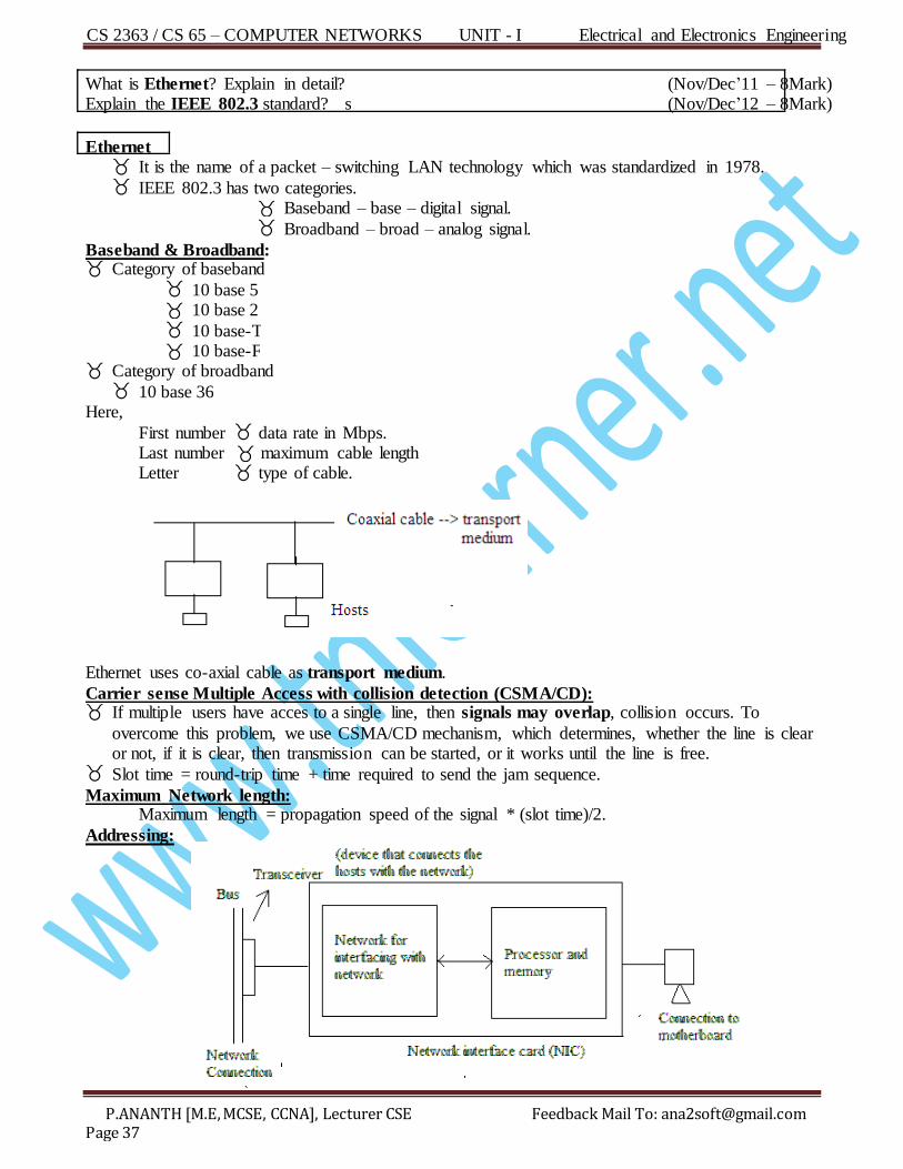
Ethernet uses co-axial cable as transport medium.
Carrier sense Multiple Access with collision detection (CSMA/CD): If multiple users have acces to a single line, then signals may overlap, collision occurs. To
overcome this problem, we use CSMA/CD mechanism, which determines, whether the line is clear or not, if it is clear, then transmission can be started, or it works until the line is free.
Slot time = round-trip time + time required to send the jam sequence.
M aximum Network length: Maximum length = propagation speed of the signal * (slot time)/2.
Addressing:
CS 2363 / CS 65 – COMPUTER NETWORKS UNIT - I Electrical and Electronics Engineering
P.ANANTH [M.E, MCSE, CCNA], Lecturer CSE Feedback Mail To: [email protected] Page 38
NIC provides each station with 6-byte physical addres.
Eg) 4A:30:10:21:10:1A
6 byte = 48 bits = 12 hex digits.
Type of addresses:
Unicast address: De fines one recipient (one to one) If the LSB of the 1sbyte is 0, then it is unicast.
t
0
Eg: 25:02:13:45:62:08
M ulticast address: De fines a group of addreses (one to many). Here, the LSB of the 1sbyte is 1.
t
Eg) 01:13:64:73:82:17
If 2s hex digit is even n d
Unicast. If 2s hex digit is odd
n d Multicast.
Broadcast address: Here, all the bits are 1’s (48 1’s).
E lectrical specification:
Signaling: Baseband systems use Manchester digital encoding. 10 broad 36 uses differential Phase shift keying.
Date rate: Ethernet supports data rates between 1 to 100 Mbps.
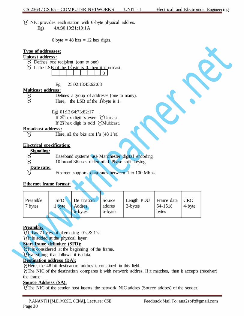
E thernet frame format: Preamble
7 bytes
SFD
1 byte
De tination
Addres 6-bytes
Source
addres 6-bytes
Length PDU
2-bytes
F rame data
64-1518 b ytes
CRC
4-byte
Preamble: It has 7 bytes of alternating 0’s & 1’s. It is added at the physical layer.
Start frame delimiter (SFD): It is considered at the beginning of the frame. Everything that follows it is data.
Destination address (DA): Here, the 48 bit destination addres is contained in this field. The NIC of the destination compares it with network addres. If it matches, then it accepts (receiver)
the frame.
Source Address (SA): The NIC of the sender host inserts the network NIC addres (Source addres) of the sender.
CS 2363 / CS 65 – COMPUTER NETWORKS UNIT - I Electrical and Electronics Engineering
P.ANANTH [M.E, MCSE, CCNA], Lecturer CSE Feedback Mail To: [email protected] Page 39
Length/type of PDU (Protocol Data Unit): Indicate the number of bytes in the PDU.
PDU data unit in the upper sup layer of the data link layer.
Frame data: Contains actual data of the frame.
CRC: This field contains the error detection information.
Generations: 4 generations are there, Ethernet evolution
Standard Ethernet F ast Ethernet Gigabit Ethernet
Ten-Gigabit Ethernet
Standard or traditional Ethernet: It defines the types of cable. Connections & signals:
Characteristics 10 Base-5 10 Base-2 10 Base-T 10 Base-F Medium Max segment length
Topology Encoding
Thick coaxial 500m
Bus Manchester
Thick coaxial 200m
Bus Manchester
Twisted pair 100m
Bus Manchester
F iber optic 2
Bus Manchester
Switched Ethernet: Here, if we use a hub and if a device sends a data, then the hub will direct the frame to all other devices. If we use a switch, then only the destination. Station will receive the frame.
Fast Ethernet: Here, the data rate is increased to 100 Mbps, & the collision is reduced.
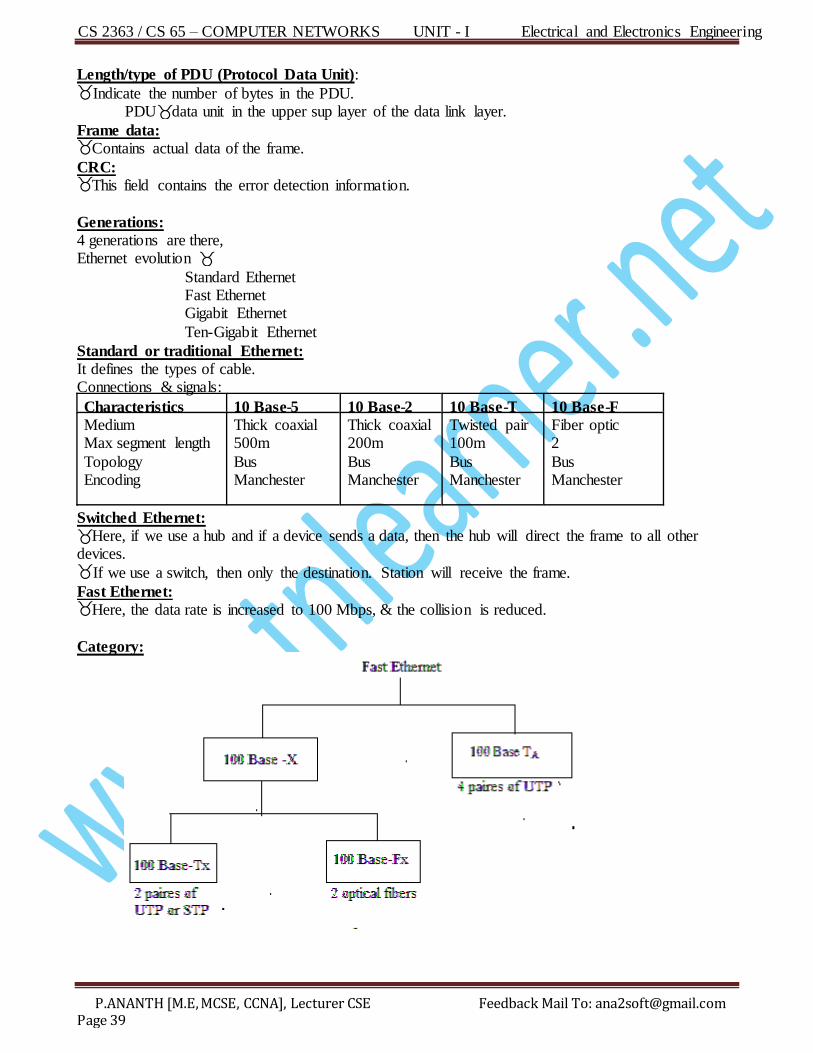
Category:
CS 2363 / CS 65 – COMPUTER NETWORKS UNIT - I Electrical and Electronics Engineering
P.ANANTH [M.E, MCSE, CCNA], Lecturer CSE Feedback Mail To: [email protected] Page 40
F eatures 100Base-Tx 100Base-Tx 100Base-Fx
Medium
Maximum Segment length
Topology
Encoding
Twisted pair(UTP)
100 m
tar
4B/5B
UTP or STP
100 m
tar
4B/5B
Optical fiber multimode
2 km
Star
8B/6T
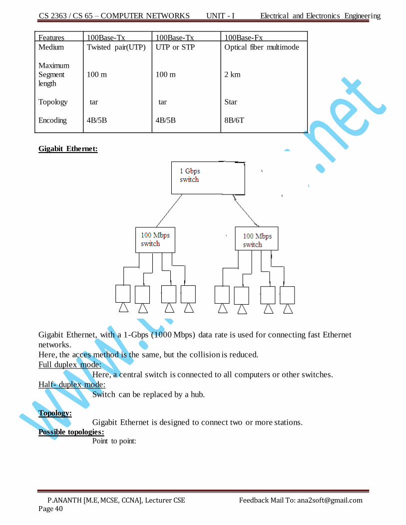
Gigabit Ethernet:
Gigabit Ethernet, with a 1-Gbps (1000 Mbps) data rate is used for connecting fast Ethernet
networks.
Here, the acces method is the same, but the collision is reduced.
Full duplex mode:
Here, a central switch is connected to all computers or other switches.
Half- duplex mode:
Switch can be replaced by a hub.
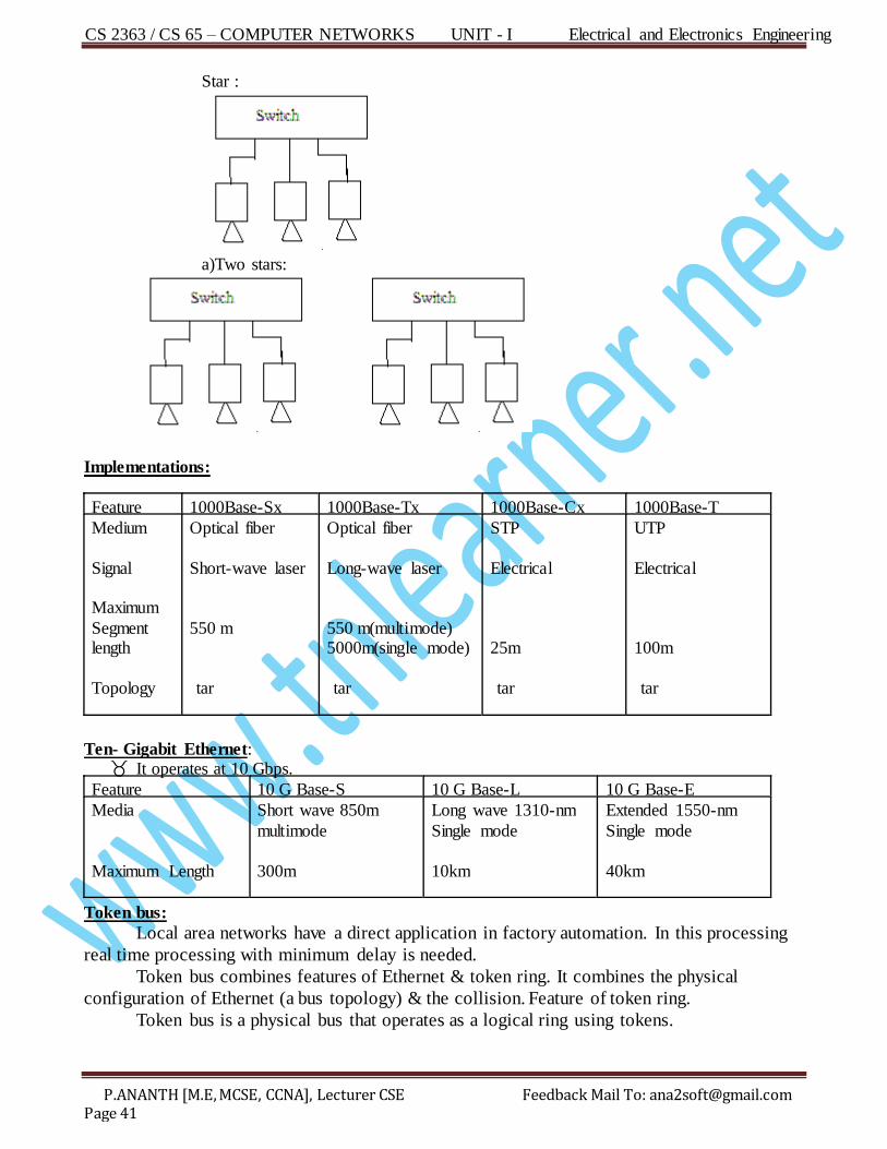
Topology:
Gigabit Ethernet is designed to connect two or more stations. Possible topologies:
Point to point:
CS 2363 / CS 65 – COMPUTER NETWORKS UNIT - I Electrical and Electronics Engineering
P.ANANTH [M.E, MCSE, CCNA], Lecturer CSE Feedback Mail To: [email protected] Page 41
Star :
a)Two stars:
Implementations:
F eature 1000Base-Sx 1000Base-Tx 1000Base-Cx 1000Base-T
Medium
Signal Maximum
Segment length
Topology
Optical fiber
Short-wave laser
550 m
tar
Optical fiber
Long-wave laser
550 m(multimode) 5000m(single mode)
tar
STP
Electrical
25m
tar
UTP
Electrical
100m
tar
Ten- Gigabit Ethernet: It operates at 10 Gbps.
F eature 10 G Base-S 10 G Base-L 10 G Base-E
Media
Maximum Length
Short wave 850m
multimode
300m
Long wave 1310-nm
Single mode
10km
Extended 1550-nm
Single mode
40km
Token bus:
Local area networks have a direct application in factory automation. In this processing
real time processing with minimum delay is needed.
Token bus combines features of Ethernet & token ring. It combines the physical
configuration of Ethernet (a bus topology) & the collision. Feature of token ring.
Token bus is a physical bus that operates as a logical ring using tokens.
CS 2363 / CS 65 – COMPUTER NETWORKS UNIT - I Electrical and Electronics Engineering
P.ANANTH [M.E, MCSE, CCNA], Lecturer CSE Feedback Mail To: [email protected] Page 42
What is FDDI? (Nov/Dec’11 – 2Mark) What is FDDI? (Nov/Dec’12 – 2Mark)
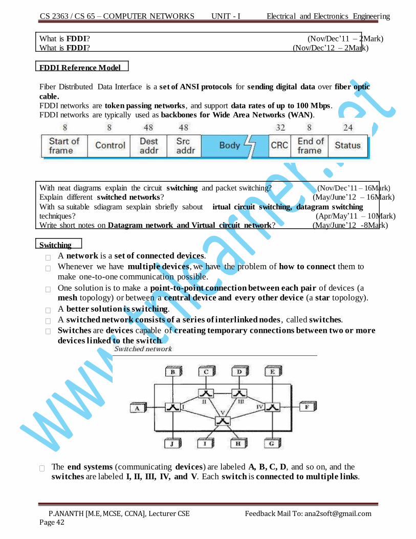
FDDI Reference Model
F iber Distributed Data Interface is a set of ANSI protocols for sending digital data over fiber optic
cable. F DD I networks are token passing networks, and support data rates of up to 100 Mbps. F DD I networks are typically used as backbones for Wide Area Networks (WAN).
With neat diagrams explain the circuit switching and packet switching? (Nov/Dec’11 – 16Mark)
Explain different switched networks? (May/June’12 – 16Mark)
With sa suitable sdiagram sexplain sbriefly sabout irtual circuit switching, datagram switching techniques? (Apr/May’11 – 10Mark) Write short notes on Datagram network and Virtual circuit network? (May/June’12 -8Mark)
Switching
A network is a set of connected devices.
Whenever we have multiple devices, we have the problem of how to connect them to
make one-to-one communication possible.
One solution is to make a point-to-point connection between each pair of devices (a mesh topology) or between a central device and every other device (a star topology).
A better solution is switching.
A switched network consists of a series of interlinked nodes , called switches.
Switches are devices capable of creating temporary connections between two or more
devices linked to the switch.
The end systems (communicating devices) are labeled A, B, C, D, and so on, and the switches are labeled I, II, III, IV, and V. Each switch is connected to multiple links.
CS 2363 / CS 65 – COMPUTER NETWORKS UNIT - I Electrical and Electronics Engineering
P.ANANTH [M.E, MCSE, CCNA], Lecturer CSE Feedback Mail To: [email protected] Page 43
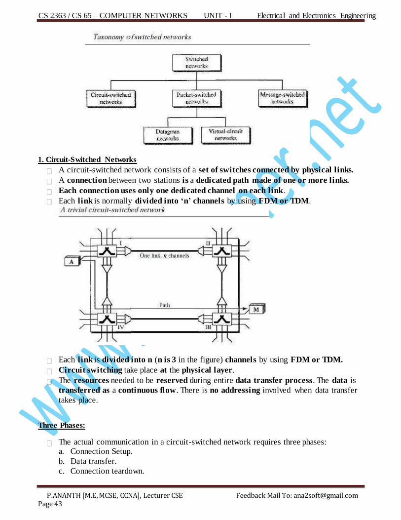
1. Circuit-Switched Networks
A circuit-switched network consists of a set of switches connected by physical links.
A connection between two stations is a dedicated path made of one or more links.
Each connection uses only one dedicated channel on each link.
Each link is normally divided into ‘n’ channels by using FDM or TDM.
Each link is divided into n (n is 3 in the figure) channels by using FDM or TDM.
Circuit switching take place at the physical layer.
The resources needed to be reserved during entire data transfer process. The data is
transferred as a continuous flow. There is no addressing involved when data transfer
takes place.
Three Phases:
The actual communication in a circuit-switched network requires three phases: a. Connection Setup.
b. Da ta transfer.
c. Connection teardown.
CS 2363 / CS 65 – COMPUTER NETWORKS UNIT - I Electrical and Electronics Engineering
P.ANANTH [M.E, MCSE, CCNA], Lecturer CSE Feedback Mail To: [email protected] Page 44
a. Connection Setup Phase
The end systems are connected through dedicated lines to the switches, so connection
setup means creating dedicated channels between the switches.
b. Data Transfer Phase
After the establishment of the dedicated circuit (channel), the end systems are can
transfer data.
c. Teardown Phase
When one of system needs to disconnect, a signal is sent to each switch to release the
resources.
E fficiency
The circuit-switched networks are not efficient as the other two types of networks
because resources are allocated sduring sthe entire duration sof the connection ( resources are dedicated).
These resources are unavailable to other connections.
Delay
In circuit-switched network normally has low efficiency, the delay in this type of network
is minimal.
During data transfer the data are not delayed at each switch; the resources are allocated
for the duration of the connection.
The total delay is due to the time needed to create the connection, transfer data, and disconnect the circuit.
How will you transmit the packets by using datagram approach? Explain in detail with a neat diagram?
(Apr/May’10 – 6Mark)
What is datagram? (Nov/Dec’04 – 2Mark)
2.Packet-Switched Networks
2.1. Datagram Networks
Datagram is an independent transmission unit in packet switching network.
In packet switching, there is no resource allocation for a packet. This means that there is
no reserved bandwidth on the links, and there is no scheduled processing time for
each packet.
Resources are allocated on demand. The allocation is done on a first-come first-served
basis.
When a switch receives a packet, no matter what is the source or destination, the packet
must wait if there are other packets being processed.
In a datagram network, each packet is treated independently of all others.
Datagram switching is normally done at the network layer.
CS 2363 / CS 65 – COMPUTER NETWORKS UNIT - I Electrical and Electronics Engineering
P.ANANTH [M.E, MCSE, CCNA], Lecturer CSE Feedback Mail To: [email protected] Page 45
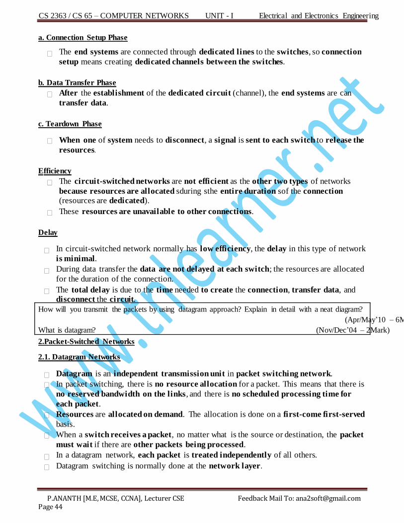
In this example, four packets (or datagram’s) belong to the same message, but may
travel different paths to reach their destination.
This approach can cause the datagrams of a transmision to arrive at their destination
out of order with different delays between the packets .
Packets may alo be lost or dropped because of a lack of resources.
Upper-layer protocol to reorder the datagrams or lost datagrams before passing them on to the application.
The datagram networks are connectionless networks.
There are no setup or teardown phases. Each packet is treated the same by a switch
regardless of its source or destination.
Routing Table
If there are no setup or teardown phases, how are the packets routed to their
destinations in a datagram network?
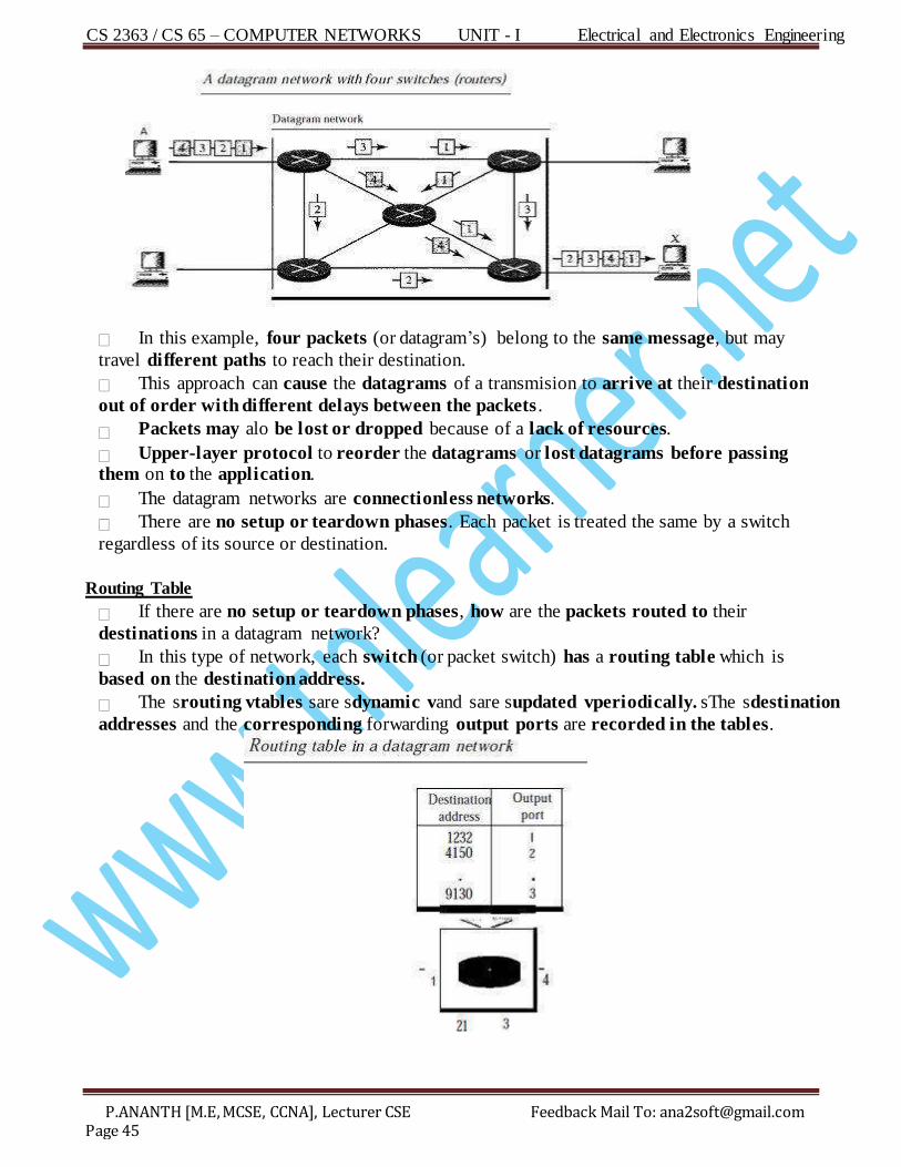
In this type of network, each switch (or packet switch) has a routing table which is
based on the destination address.
The srouting vtables sare sdynamic vand sare supdated vperiodically. sThe sdestination
addresses and the corresponding forwarding output ports are recorded in the tables.
CS 2363 / CS 65 – COMPUTER NETWORKS UNIT - I Electrical and Electronics Engineering
P.ANANTH [M.E, MCSE, CCNA], Lecturer CSE Feedback Mail To: [email protected] Page 46
Destination Address
Every packet in a datagram network carries a header that contains, among other information, the destination address of the packet.
When the switch receives the packet, this destination address is examined; the routing table is consulted to find the corresponding port through which the packet hould
be forwarded.
E fficiency
The sefficiency sof sa sdatagram snetwork sis sbetter vthan sthat sof sa scircuit-switched network; resources are allocated only when there are packets to be transferred.
If a source sends a packet and there is a delay of a few minutes before another packet
can be sent, the resources can be reallocated during these minutes for other packets
from other sources.
Delay
There may be greater delay in a datagram network than in a sirtual-circuit network.
Although there are no setup and teardown phases, each packet may experience a wait
at a switch before it is forwarded.
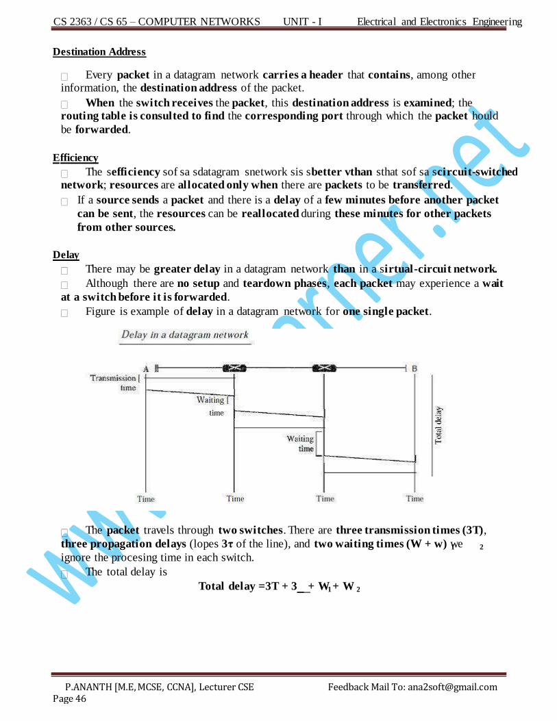
Figure is example of delay in a datagram network for one single packet.
The packet travels through two switches. There are three transmission times (3T),
three propagation delays (lopes 3τ of the line), and two waiting times (W + w) we 1 2
ignore the procesing time in each switch.
The total delay is
Total delay =3T + 3 __ _ _ + W + W 1 2
CS 2363 / CS 65 – COMPUTER NETWORKS UNIT - I Electrical and Electronics Engineering
P.ANANTH [M.E, MCSE, CCNA], Lecturer CSE Feedback Mail To: [email protected] Page 47
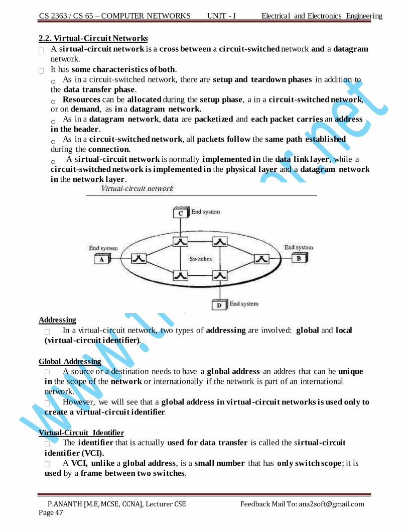
2.2. Virtual-Circuit Networks
A sirtual-circuit network is a cross between a circuit-switched network and a datagram
network.
It has some characteristics of both.
o As in a circuit-switched network, there are setup and teardown phases in addition to
the data transfer phase.
o Resources can be allocated during the setup phase, a in a circuit-switched network, or on demand, as in a datagram network.
o As in a datagram network, data are packetized and each packet carries an address
in the header.
o As in a circuit-switched network, all packets follow the same path established
during the connection.
o A sirtual-circuit network is normally implemented in the data link layer, while a
circuit-switched network is implemented in the physical layer and a datagram network
in the network layer.
Addressing
In a virtual-circuit network, two types of addressing are involved: global and local
(virtual-circuit identifier).
Global Addressing
A source or a destination needs to have a global address-an addres that can be unique
in the scope of the network or internationally if the network is part of an international
network.
However, we will see that a global address in virtual-circuit networks is used only to
create a virtual-circuit identifier.
Virtual-Circuit Identifier
The identifier that is actually used for data transfer is called the sirtual-circuit
identifier (VCI).
A VCI, unlike a global address, is a small number that has only switch scope; it is
used by a frame between two switches.
CS 2363 / CS 65 – COMPUTER NETWORKS UNIT - I Electrical and Electronics Engineering
P.ANANTH [M.E, MCSE, CCNA], Lecturer CSE Feedback Mail To: [email protected] Page 48
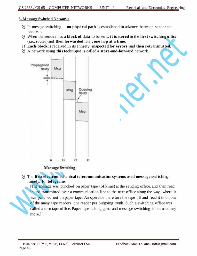
3 . Message Switched Networks
In mesage switching no physical path is established in advance between sender and
receiver.
When the sender has a block of data to be sent, it is stored in the first switching office
(i.e., router) and then forwarded later, one hop at a time.
Each block is received in its entirety, inspected for errors, and then retransmitted. A network using this technique is called a store-and-forward network.
The first electromechanical telecommunication systems used message switching,
namely, for telegrams.
[The mesage was punched on paper tape (off-line) at the sending office, and then read
in and transmitted over a communication line to the next office along the way, where it
was punched out on paper tape. An operator there tore the tape off and read it in on one
of the many tape readers, one reader per outgoing trunk. Such a switching office was
called a torn tape office. Paper tape is long gone and message switching is not used any
more.]
CS 2363 / CS 65 – COMPUTER NETWORKS UNIT - I Electrical and Electronics Engineering
P.ANANTH [M.E, MCSE, CCNA], Lecturer CSE Feedback Mail To: [email protected] Page 49
Write a note on bridges? (Nov/Dec’11 – 8Mark) What is the main function of a bridge? (May/June’11- 2Mark)
Dr aw the line diagram of a LAN showing the location of a BRIDGE? (Nov/Dec’11 – 2Mark)
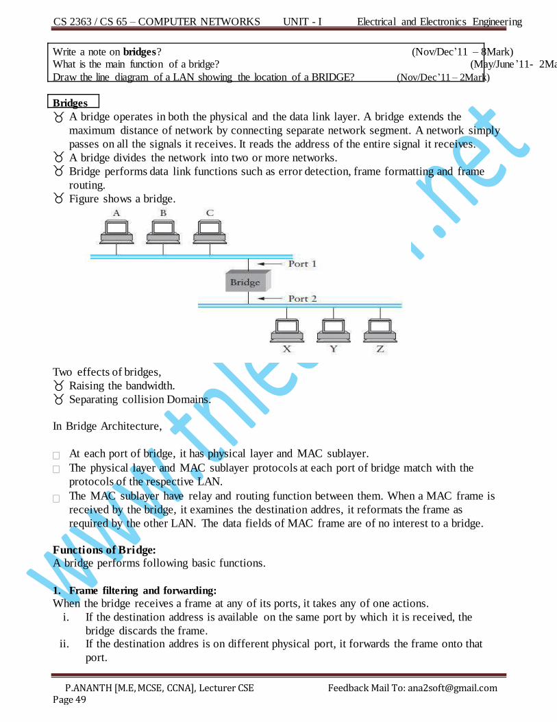
Bridges
A bridge operates in both the physical and the data link layer. A bridge extends the
maximum distance of network by connecting separate network segment. A network simply
passes on all the signals it receives. It reads the address of the entire signal it receives. A bridge divides the network into two or more networks. Bridge performs data link functions such as error detection, frame formatting and frame
routing. Figure shows a bridge.
Two effects of bridges, Raising the bandwidth. Separating collision Domains.
In Bridge Architecture,
At each port of bridge, it has physical layer and MAC sublayer.
The physical layer and MAC sublayer protocols at each port of bridge match with the
protocols of the respective LAN.
The MAC sublayer have relay and routing function between them. When a MAC frame is
received by the bridge, it examines the destination addres, it reformats the frame as
required by the other LAN. The data fields of MAC frame are of no interest to a bridge.
Functions of Bridge: A bridge performs following basic functions.
1. Frame filtering and forwarding:
When the bridge receives a frame at any of its ports, it takes any of one actions.
i. If the destination address is available on the same port by which it is received, the
bridge discards the frame. ii. If the destination addres is on different physical port, it forwards the frame onto that
port.
CS 2363 / CS 65 – COMPUTER NETWORKS UNIT - I Electrical and Electronics Engineering
P.ANANTH [M.E, MCSE, CCNA], Lecturer CSE Feedback Mail To: [email protected] Page 50
iii. If the bridge does not find the destination address, it forwards the frame over all its physical ports except from which it is received.
2. Learning the address:
When a frame is received at a bridge and if source address is not available in the
database, it updates the database. This entry consists of the address, port on which
address was received and a timer value when the addres was arrived.
3. Routing:
When multiple LANs and multiple interconnecting bridges are configured, the bridges
need to have routing capability. The bridge must know the alternative routes and their
associated costs in terms of number of hops. Alternative and duplicate routes must be
distinguished. In the network duplicate routes interfere in the self address learning
mechanism. The process of deciding which frames to forward and where is called
bridge routing.
Part - A 1. Give two differences between connection oriented and connectionless services? (Nov/Dec’03 – 2Mark)
Sl.No Connection oriented Connectionless
1 . A connection is established
Between sender and receiver
No connection establishment.
2. Packets are numbered. Packets are not numbered.
3. Acknowledgement for each packet. No Acknowledgement
2. Differences between hub and switch? (Nov/Dec’03 – 2Mark)
Sl.No Hub Switch
1 . Uses broadcast communication. Point-to-point communication.
2. Operates at physical layer. Operates at data link layer.
3. Not an intelligent device. An intelligent device.
4 . Cannot be used as repeater. Can be used as repeater.
3. Differences between router and gateway? ( Nov/Dec’03 – 2Mark)
Sl.No Router Gateway
1 . Router operates at network layer. Gateway operates at application layer.
2. Router does not convert protocol. Gateway converts protocol.
4. What is datagram?(Nov/Dec’04 – 2Mark)
Da tagram is an independent transmision unit in a packets switching network.
5. Define datagram?
Da tagram is the basic transmission unit in the Internet architecture. A datagram contains all of
the information needed to deliver it to its destination. Datagram networks are Connectionles.
6. What are the most common error control techniques? (Nov/Dec’04 – 2Mark)
1. Stop-and-Wait ARQ
2. Go-Back-N ARQ
3. Selective Repeat ARQ