Embed Size (px)
Citation preview
30 LIFT-REPORT 40. Jahrg. (2014) Heft 3
Comprehensive Ride Quality Analysis at a Glance
It is not unusual to meet with elevators in practice which reveal potential for optimization concerning ride quality. In many cases, there is a demand for a meaningful and comprehensive analysis of the entire elevator facility in order to eliminate unwanted vibrations and resonances systematically and fast in a following step.
For an objective analysis and evaluation of the ride quality, ISO Standard 18 738 exists. Among other things, this Stand-ard makes predefined demands on the measuring equip-ment, the measuring setup and the analysis of the measur-ing results. In this way, it provides certain comparability – even at using different types of measuring equipment. The obvi-ous advantages are opposed by several disadvantages which are not or just partly obvious to the users. This shall be briefly discussed in the following.
A common problem of the ISO Standard occurs at the con-ducted lowpass filtering (smoothing). The serious disadvan-tage of this filtering routine is due to an inappropriate cut-ting-off of the frequency boundaries in which troublesome vibrations possibly exist. These vibrations are consequently no longer visible in the measuring result.
Aside from the before mentioned potential negative conse-quences of the smoothing, the selection of the evaluated time boundaries (travel sections) is also not unproblematic: Within the ISO specification, it is not secured that travel sections are chosen properly in order to consider all rele-vant vibrations and resonances within the scope of the measurement. By an inappropriate choice of the travel sec-tions, the entire elevator facility can possibly achieve a pos-itive ride quality analysis result although extensive oscilla-tions and interferences can still be noticed by human sense organ. In this case, measurement and analysis results are insufficient as well.
The following use cases shall illustrate the problems men-tioned above and show that these actually occur in practice by strict use of the ISO Standard 18 738. In addition, an al-ternative possibility for comprehensive ride quality analy-ses with the help of the innovative LiKoS Mini Recorders1) is introduced. Hereby, the obvious gaps of the ISO Standard can be closed and a perfect overview of the condition of an elevator facility can be obtained in a simple but very effi-cient way.
All measurements are taken with LiKoS Mini Recorders as these instruments provide analyses in accordance with ISO Standard as well as with the innovative LiKoS method.
Use Case 1: Inappropriate lowpass filtering of frequencies
In this particular example from practice, there was a com-plaint of the users of an elevator facility in a residential building with a hoisting height of 35 meters. The residents complained about vibrations and called vehemently for elimination of these droning noises. A ride quality analysis
Matthias Gehrke, Dr. Björn Graßl, Dr. Sebastian Sigle
conducted by experts in accordance with ISO Standard 18 738 could not provide any information about the nature and origin of these noises at all2).
In order to overcome the before mentioned possible rea-sons for the non-measurability of these vibrations (in ac-cordance with ISO Standard 18 738) and to simultaneously provide a comprehensive analysis of the elevator, LiKoS Mi-ni Recorders were used for a second measurement of the facility.
First of all, with the help of the nominal engine speed (1.470 revolutions per minute), the frequency of the engine was determined : 24,5 Hz. One is able to measure this frequency very well at the engine frame with the help of the LiKoS Mini Recorders. For this, one Mini Recorder is attached to the engine and a second one to the bottom of the cabin. In this way, vibrations of the engine can be illustrated precisely in the LiKoS software in addition to the travel curve (see figure 2).
The figures 3 and 4 show that the harmonic multiples of the fundamental frequency are apparently less cushioned than the causal originating frequency. The higher frequencies are passed on to the cabin through the ropes (see frequen-cy spectrum).
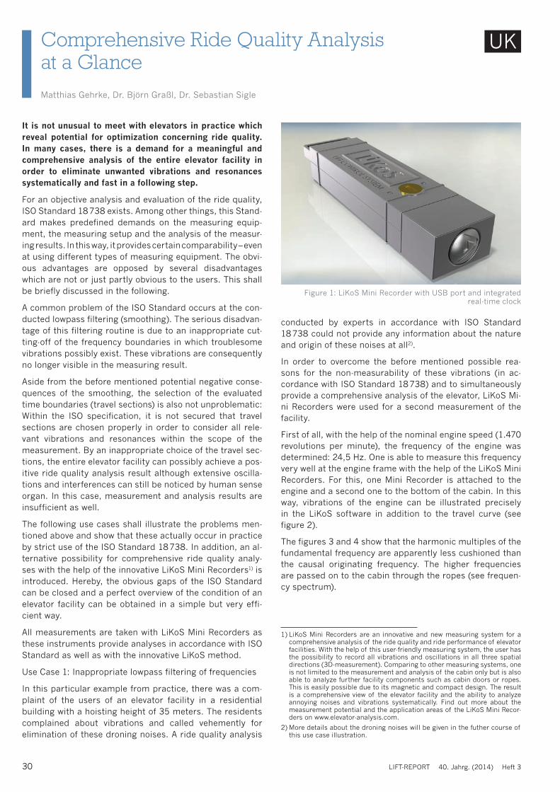
Figure 1: LiKoS Mini Recorder with USB port and integrated real-time clock
1) LiKoS Mini Recorders are an innovative and new measuring system for a comprehensive analysis of the ride quality and ride performance of elevator facilities. With the help of this user-friendly measuring system, the user has the possibility to record all vibrations and oscillations in all three spatial directions (3D-measurement). Comparing to other measuring systems, one is not limited to the measurement and analysis of the cabin only but is also able to analyze further facility components such as cabin doors or ropes. This is easily possible due to its magnetic and compact design. The result is a comprehensive view of the elevator facility and the ability to analyze annoying noises and vibrations systematically. Find out more about the measurement potential and the application areas of the LiKoS Mini Recor-ders on www.elevator-analysis.com.
2) More details about the droning noises will be given in the futher course of this use case illustration.
UK
European Lift Association ELA
Verband deutscher Maschinen-und Anlagenbau eV VDMA
Verband für Aufzugstechnik VFA-Interlift eV
Verband der technischenÜberwachungsvereine VdTÜV
Technical Academy of Heilbronn e.V.Institute for further Education and Training at Heilbronn University
October 7, 2014
Check-in from 8.00 am – Start at 9.00 am
Welcome Georg Clauss, TAH eV
Introduction Gerhard Schiffner, ThyssenKrupp
Philippe Lamalle ● ELA, Brussels
Lifts for the future of Europe
Veronique Spreadbury ● Otis, France
Product liability and traceabilityaccording to new Lifts Directive
Ana Maria Lorente LafuenteISO/TC178/WG10 expert, Spain
Energy performance of lifts acc to ISO 25745-2
Nikolay Minkow ● TU Berlin, Germany
ISO 14025 and Product Category Rules for liftsbackground and current developments
Lunch break
Dirk Preissl ● Fire Dept. Dusseldorf, Germany
Fire fighting lifts acc to revised EN 81-72
Ashiqur Rahman ● Mitsubishi Elevator, Netherlands
New concept of evacuation lift
Petteri Valjus ● KONE, Finland
First leap with light weight technology – KONE UltraRope™
Sven Winter ● TU Stuttgart, Germany
Rope research at the University of Stuttgart
Visit at the Institute of Mechanical Handling and Logistics
End approx. 6.30 pm
Conference Dinner
Start 9.00 am
Stefan Kaczmarczyk● Univ. of Northampton, GB
The prediction and analysis of dynamic behaviour and vibrations of lift systems
Etienne Nitidem ● Wittur Holding, GermanyModelling and simulation of the dynamic behaviour
of lift systems with cantilever car slings
Peter Herkel ● Otis, Germany
System analysis and architecture methodologiesto drive innovative electrical systems
Carl van den Einden ● Liftinstituut, Netherlands
Service lifts in wind turbines - which safety rules are applicable
Lunch break
Principles of EN 81-20/-50 by CEN/TC10 experts
Esfandiar GharibaanBackground and development road map
Ian Jones, Gerhard SchiffnerMechanical equipment
Ari KattainenElectrical equipment
Panel discussion - Ask the experts
Gerhard SchiffnerSummary and closure of the congress
End approx. 4.00 pm
Subject to modifications
Information and Registration
Participation fee: 825,- € (VAT free) incl. brochure, lunch, snacks and evening function
Registration and further Information from now on:Technische Akademie Heilbronn e. V.Max-Planck-Str. 39 ● 74081 Heilbronn ● [email protected] ● TAH.hs-heilbronn.de/elchTel: +497131568063 ● Fax: +497131568065
6th European Lift Congress HeilbronnNew Regulations - Sustainability - Technical Innovation
Concept and Chair: Dr. Gerhard Schiffner
October 8, 2014
supported byCongress LocationHotel Maritim • Stuttgart
booking code for
reserved rooms: ELCH2014
32 LIFT-REPORT 40. Jahrg. (2014) Heft 3
As a consequence, the actual reason – the fundamental fre-quency of 24.53 Hz – is hardly traceable there. On the con-trary, the droning frequency of 73.4 Hz can fully develop.
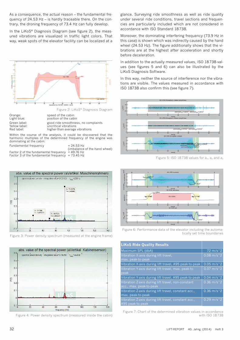
In the LiKoS® Diagnosis Diagram (see figure 2), the meas-ured vibrations are visualized in traffic light colors. That way, weak spots of the elevator facility can be localized at a
glance. Surveying ride smoothness as well as ride quality under several ride conditions, travel sections and frequen-cies are particularly included which are not considered in accordance with ISO Standard 18 738.
Moreover, the dominating interfering frequency (73.9 Hz in this case) is shown which was indirectly caused by the hand wheel (24.53 Hz). The figure additionally shows that the vi-brations are at the highest after acceleration and shortly before deceleration.
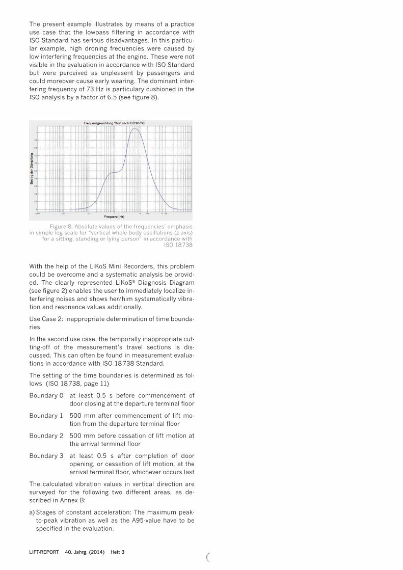
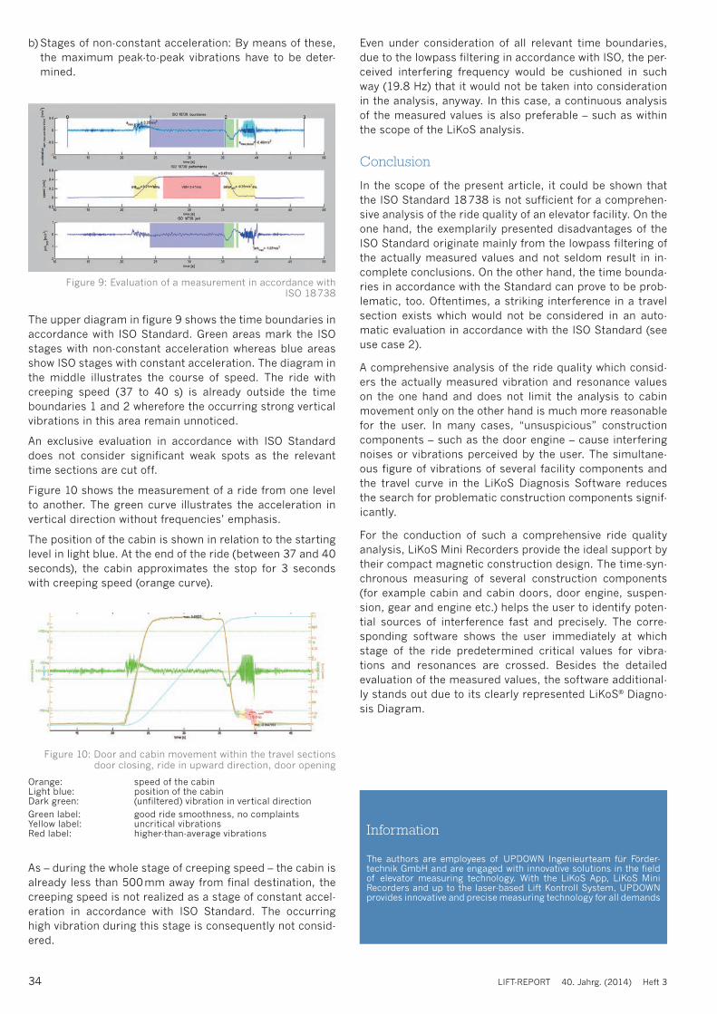
In addition to the actually measured values, ISO 18 738-val-ues (see figures 5 and 6) can also be illustrated by the LiKoS Diagnosis Software.
In this way, neither the source of interference nor the vibra-tions are visible. The values measured in accordance with ISO 18738 also confirm this (see figure 7).
Figure 2: LiKoS® Diagnosis Diagram
Orange: speed of the cabinLight blue: position of the cabinGreen label: good ride smoothness, no complaintsYellow label: uncritical vibrationsRed label: higher-than-average vibrations
Within the course of the analysis, it could be discovered that the harmonic multiples of the determined frequency of the engine was dominating at the cabin:Fundamental frequency = 24.53 Hz (imbalance of the hand wheel)Factor 2 of the fundamental frequency = 49.76 HzFactor 3 of the fundamental frequency = 73.45 Hz
Figure 3: Power density spectrum (measured at the engine frame)
Figure 4: Power density spectrum (measured inside the cabin)
Figure 5: ISO 18 738 values for ax, ay and az
Figure 6: Performance data of the elevator including the automa-tically set time boundaries
LiKoS Ride Quality Results
Maximum SPL (dbA) 72 m/s^2Vibration X-axis during lift travel, max. peak-to-peak
0.08 m/s^2
Vibration X-axis during lift travel, A95 peak-to-peak 0.05 m/s^2Vibration Y-axis during lift travel, max. peak-to-peak
0.07 m/s^2
Vibration Y-axis during lift travel, A95 peak-to-peak 0.04 m/s^2Vibration Z-axis during lift travel, non-constant acc., max. peak-to-peak
0.36 m/s^2
Vibration Z-axis during lift travel, constant acc., max. peak-to-peak
0.36 m/s^2
Vibration Z-axis during lift travel, constant acc., A95 peak-to-peak
0.29 m/s^2
Figure 7: Chart of the determined vibration values in accordance with ISO 18 738
LIFT-REPORT 40. Jahrg. (2014) Heft 3
Anzeigen 1/2 S._NeoVision Anzeige 16.12.13 11:26 Seite 1
The present example illustrates by means of a practice use case that the lowpass filtering in accordance with ISO Standard has serious disadvantages. In this particu-lar example, high droning frequencies were caused by low interfering frequencies at the engine. These were not visible in the evaluation in accordance with ISO Standard but were perceived as unpleasent by passengers and could moreover cause early wearing. The dominant inter-fering frequency of 73 Hz is particulary cushioned in the ISO analysis by a factor of 6.5 (see figure 8).
Figure 8: Absolute values of the frequencies’ emphasis in simple log scale for “vertical whole-body oscillations (z-axis)
for a sitting, standing or lying person” in accordance with ISO 18 738
With the help of the LiKoS Mini Recorders, this problem could be overcome and a systematic analysis be provid-ed. The clearly represented LiKoS® Diagnosis Diagram (see figure 2) enables the user to immediately localize in-terfering noises and shows her/him systematically vibra-tion and resonance values additionally.
Use Case 2: Inappropriate determination of time bounda-ries
In the second use case, the temporally inappropriate cut-ting-off of the measurement’s travel sections is dis-cussed. This can often be found in measurement evalua-tions in accordance with ISO 18 738 Standard.
The setting of the time boundaries is determined as fol-lows (ISO 18 738, page 11)
Boundary 0 at least 0.5 s before commencement of door closing at the departure terminal floor
Boundary 1 500 mm after commencement of lift mo-tion from the departure terminal floor
Boundary 2 500 mm before cessation of lift motion at the arrival terminal floor
Boundary 3 at least 0.5 s after completion of door opening, or cessation of lift motion, at the arrival terminal floor, whichever occurs last
The calculated vibration values in vertical direction are surveyed for the following two different areas, as de-scribed in Annex B:
a) Stages of constant acceleration: The maximum peak-to-peak vibration as well as the A95-value have to be specified in the evaluation.
LIFT-REPORT 40. Jahrg. (2014) Heft 3
34 LIFT-REPORT 40. Jahrg. (2014) Heft 3
LEMoSDie modulare Modernisierungslösung,die sich optimal an Ihre Bedürfnisse anpasst
Möchten Sie mehr über LEMoS erfahren? Kontaktieren Sie uns!
LiftEquip GmbH Elevator ComponentsBernhäuser Straße 45 ● D-73765 Neuhausen a.d.F.Tel.: +49 (0) 71 58 12 - 2929 ● Fax: +49 (0) 71 58 12 - 2971E-Mail: [email protected] ● Internet: www.liftequip.de
b) Stages of non-constant acceleration: By means of these, the maximum peak-to-peak vibrations have to be deter-mined.
Figure 9: Evaluation of a measurement in accordance with ISO 18 738
Figure 10: Door and cabin movement within the travel sections door closing, ride in upward direction, door opening
Orange: speed of the cabinLight blue: position of the cabin Dark green: (unfiltered) vibration in vertical directionGreen label: good ride smoothness, no complaintsYellow label: uncritical vibrationsRed label: higher-than-average vibrations
Even under consideration of all relevant time boundaries, due to the lowpass filtering in accordance with ISO, the per-ceived interfering frequency would be cushioned in such way (19.8 Hz) that it would not be taken into consideration in the analysis, anyway. In this case, a continuous analysis of the measured values is also preferable – such as within the scope of the LiKoS analysis.
Conclusion
In the scope of the present article, it could be shown that the ISO Standard 18 738 is not sufficient for a comprehen-sive analysis of the ride quality of an elevator facility. On the one hand, the exemplarily presented disadvantages of the ISO Standard originate mainly from the lowpass filtering of the actually measured values and not seldom result in in-complete conclusions. On the other hand, the time bounda-ries in accordance with the Standard can prove to be prob-lematic, too. Oftentimes, a striking interference in a travel section exists which would not be considered in an auto-matic evaluation in accordance with the ISO Standard (see use case 2).
A comprehensive analysis of the ride quality which consid-ers the actually measured vibration and resonance values on the one hand and does not limit the analysis to cabin movement only on the other hand is much more reasonable for the user. In many cases, “unsuspicious” construction components – such as the door engine – cause interfering noises or vibrations perceived by the user. The simultane-ous figure of vibrations of several facility components and the travel curve in the LiKoS Diagnosis Software reduces the search for problematic construction components signif-icantly.
For the conduction of such a comprehensive ride quality analysis, LiKoS Mini Recorders provide the ideal support by their compact magnetic construction design. The time-syn-chronous measuring of several construction components (for example cabin and cabin doors, door engine, suspen-sion, gear and engine etc.) helps the user to identify poten-tial sources of interference fast and precisely. The corre-sponding software shows the user immediately at which stage of the ride predetermined critical values for vibra-tions and resonances are crossed. Besides the detailed evaluation of the measured values, the software additional-ly stands out due to its clearly represented LiKoS® Diagno-sis Diagram.
The authors are employees of UPDOWN Ingenieurteam für Förder-technik GmbH and are engaged with innovative solutions in the field of elevator measuring technology. With the LiKoS App, LiKoS Mini Recorders and up to the laser-based Lift Kontroll System, UPDOWN provides innovative and precise measuring technology for all demands
Information
As – during the whole stage of creeping speed – the cabin is already less than 500 mm away from final destination, the creeping speed is not realized as a stage of constant accel-eration in accordance with ISO Standard. The occurring high vibration during this stage is consequently not consid-ered.
The upper diagram in figure 9 shows the time boundaries in accordance with ISO Standard. Green areas mark the ISO stages with non-constant acceleration whereas blue areas show ISO stages with constant acceleration. The diagram in the middle illustrates the course of speed. The ride with creeping speed (37 to 40 s) is already outside the time boundaries 1 and 2 wherefore the occurring strong vertical vibrations in this area remain unnoticed.
An exclusive evaluation in accordance with ISO Standard does not consider significant weak spots as the relevant time sections are cut off.
Figure 10 shows the measurement of a ride from one level to another. The green curve illustrates the acceleration in vertical direction without frequencies’ emphasis.
The position of the cabin is shown in relation to the starting level in light blue. At the end of the ride (between 37 and 40 seconds), the cabin approximates the stop for 3 seconds with creeping speed (orange curve).
![Main Congress - Home | · Regine Heilbronn [CHARITÉ MEDICAL UNIVERSITY BERLIN] ... Main Congress Programme Thursday 19 October 2017 INV Invited speaker • OR Selected abstracts](https://img.pdfslide.us/doc/110x75/5c41f9e393f3c338c80d2b12/main-congress-home-regine-heilbronn-charite-medical-university-berlin.jpg)