Embed Size (px)
Citation preview
Composer Software
For support mail to: tech‐support@smac‐mca.nl
See also our website: www.smac‐mca.com
Software Manual Revision 1.2
www.ingeniamc.com
Composer – Software Manual Copyright and trademarks Copyright © 2011 INGENIA-CAT, S.L. Disclaimers and limitations of liability Except in cases specifically indicated in other agreements and INGENIA‐CAT, this product and its documentation are provided “as is”, with no warranties or conditions of any type, whether express or implied, including, but not limited to the implied warranties or conditions of merchantability, fitness for a particular purpose or non‐infringement. INGENIA‐CAT rejects all liability for errors or omissions in the information or the product or in other documents mentioned in this document. INGENIA‐CAT shall in no event be liable for any incidental, accidental, indirect or consequential damages (including but not limited to those resulting from: (1) dependency of equipment presented, (2) costs or substituting goods, (3) impossibility of use, loss of profit or data, (4) delays or interruptions to business operations (5) and any other theoretical liability that may arise as a consequence of the use or performance of information, irrespective of whether INGENIA‐CAT has been notified that said damage may occur. Some countries do not allow the limitation or exclusion of liability for accidental or consequential damages, meaning that the limits or exclusions stated above may not be valid in some cases. This document may contain technical or other types of inaccuracies. This information changes periodically.
Contents
Introduction ..................................................................................................................................... 3 1.1 Getting Started ....................................................................................................................... 3 1.2 Composer Desktop ................................................................................................................ 3 1.2.1 Composer windows ....................................................................................................... 4 1.2.1 Composer toolbars ......................................................................................................... 5 1.2.1 Composer Menu Bar ...................................................................................................... 6 1.2.1 Composer Status Bar ...................................................................................................... 7
Connecting to the Drive ................................................................................................................ 8 2.1 Network wizard dialog ........................................................................................................ 8 2.1.1 RS232 network configuration ....................................................................................... 8 2.1.2 CAN/CANopen network configuration .................................................................... 10
2.2 Drive connection.................................................................................................................. 11 Drive State ..................................................................................................................................... 13 3.1 Finite state automaton ........................................................................................................ 13
Programming interface ................................................................................................................ 16 4.1 Creating a Program File ................................................................................................ 16 4.1.1 Adding instructions ..................................................................................................... 17 4.1.2 Adding requests ........................................................................................................... 17
4.3 Opening/Saving Program Files ......................................................................................... 18 4.4 Downloading programs to Drive ...................................................................................... 18 4.4 Uploading programs from Drive ...................................................................................... 18 4.5 Debugging ............................................................................................................................ 19 4.6 Registers pane ...................................................................................................................... 19 4.7 Drive Memory pane ............................................................................................................ 20 4.8 Interrupt System .................................................................................................................. 20 4.9 Managing Memory .............................................................................................................. 21
Command reference ..................................................................................................................... 23 5.1 Operation commands ................................................................................................... 23 5.1.1 Macro Access ................................................................................................................. 23 5.1.2 Macro Commands ........................................................................................................ 24 5.1.2 Register Commands ..................................................................................................... 25 5.1.2 Sequence Commands ................................................................................................... 30
5.2 Drive commands ........................................................................................................... 36 5.3 General purpose registers commands ........................................................................ 36
Icons
Icons that the reader may encounter in this manual are shown below, together with their meanings.
Additional information Provides the user with tips, tricks and other useful data.
WarningProvides the user with important information. Ignoring this warning may cause the device not to work properly.
Critical warning Provides the user with critical information. Ignoring this critical warning may cause damage to the device.
2
1 Introduction
The Ingenia Composer is a graphical user interface for developing and debugging programs for Ingenia Servo Drive Controllers. The Ingenia Composer software combined with an Ingenia Digital Servo Drive, creates a powerful single axis motion tool that can be programmed by anyone with basic computer and motion control knowledge. The Composer software allows for developing a program and then downloads it in the onboard nonvolatile RAM (NVRAM) of the Servo Drive Controller. On the controller, the program is run on its internal Virtual Machine. Programs, also called ʺmacrosʺ, are created by one or more instructions (with arguments) that can combine moves, gains adjustments, timed delays, etc. Program instructions can also apply conditional logic and jumping, control the Servo Drive’s digital outputs, and monitor the digital inputs. Several general purpose registers can also be used for user convenience. The user can create and download up to 64 different macros with up to 64 instructions each. Macro calls via the Macro Call command may be nested up to 25 calls deep. Macro ʺ0ʺ is always executed on power‐up. Other macros need to be called explicitly or by means of an interrupt source.
1.1 Getting Started
Minimum computer requirements to run Composer software are: • Microsoft Windows OS version 2000, XP, Vista or 7. • Processor 1GHZ or higher with at least 64Mb of RAM. • At least 50MB of free disk space. • USB or Serial COM port for controller serial connection. • CAN port for CAN connection [optional]. In order to install and run the Composer software, you must have Administrator privileges (for installation). After installing the Composer software on your computer, you can run the application from your Start > Programs menu.
1.2 Composer Desktop
Upon accessing the Composer software, you will see a set of windows/panes that can be opened and closed, and manipulated as needed. Across the top, as in most Windows applications, is the menu bar, with several movable toolbars beneath it.
Chapter 1: Introduction 3
1.2.1 Composer windows
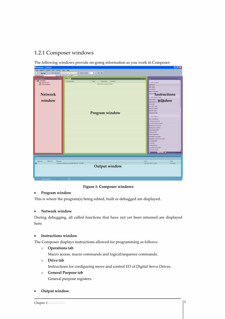
The following windows provide on‐going information as you work in Composer:
Figure 1: Composer windows
Program window
Network window
Output window
Instructions window
• Program window This is where the program(s) being edited, built or debugged are displayed. • Network window During debugging, all called functions that have not yet been returned are displayed here. • Instructions window The Composer displays instructions allowed for programming as follows:
o Operations tab Macro access, macro commands and logical/sequence commands.
o Drive tab Instructions for configuring move and control I/O of Digital Servo Drives.
o General Purpose tab General purpose registers.
• Output window
Chapter 1: Introduction 4
This window displays a list of the most recent system messages concerning communication between the host and the connected drive.
1.2.1 Composer toolbars
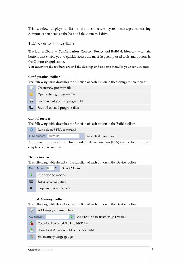
The four toolbars — Configuration, Control, Device and Build & Memory —contain buttons that enable you to quickly access the most frequently‐used tools and options in the Composer application. You can move the toolbars around the desktop and relocate them for your convenience. Configuration toolbar The following table describes the function of each button in the Configuration toolbar.
Create new program file
Open existing program file
Save currently active program file
Save all opened program files
Control toolbar The following table describes the function of each button in the Build toolbar.
Run selected FSA command
Select FSA command
Additional information on Drive Finite State Automaton (FSA) can be found in next chapters of this manual. Device toolbar The following table describes the function of each button in the Device toolbar.
Select Macro
Run selected macro
Reset selected macro
Stop any macro execution
Build & Memory toolbar The following table describes the function of each button in the Device toolbar.
Add empty comment line
Add request instruction (get value)
Download selected file into NVRAM
Download All opened files into NVRAM
See memory usage gauge
Chapter 1: Introduction 5
Open project properties dialog
Show/Hide use constants in program window
Show/Hide comments in program window
Show/Hide index/subindex information
Show/Hide generated code in program window
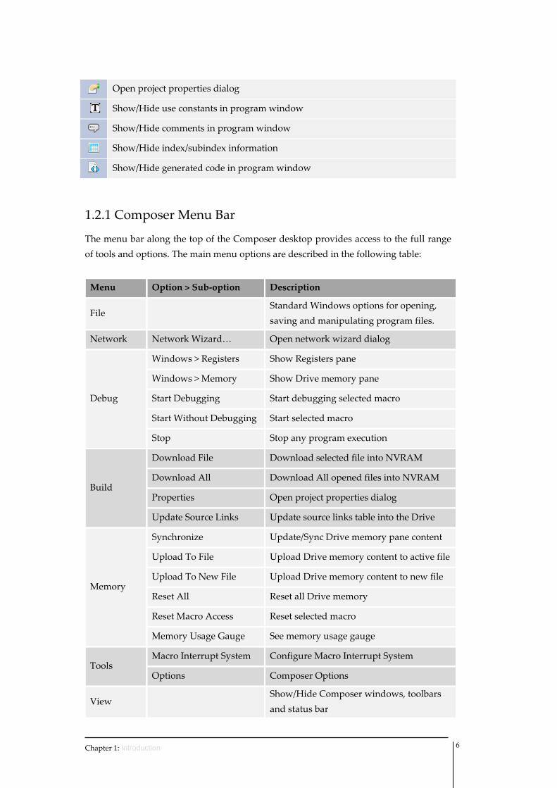
1.2.1 Composer Menu Bar
The menu bar along the top of the Composer desktop provides access to the full range of tools and options. The main menu options are described in the following table:
Menu Option > Sub‐option Description
File Standard Windows options for opening, saving and manipulating program files.
Network Network Wizard… Open network wizard dialog
Debug
Windows > Registers Show Registers pane
Windows > Memory Show Drive memory pane
Start Debugging Start debugging selected macro
Start Without Debugging Start selected macro
Stop Stop any program execution
Build
Download File Download selected file into NVRAM
Download All Download All opened files into NVRAM
Properties Open project properties dialog
Update Source Links Update source links table into the Drive
Memory
Synchronize Update/Sync Drive memory pane content
Upload To File Upload Drive memory content to active file
Upload To New File Upload Drive memory content to new file
Reset All Reset all Drive memory
Reset Macro Access Reset selected macro
Memory Usage Gauge See memory usage gauge
Tools Macro Interrupt System Configure Macro Interrupt System
Options Composer Options
View Show/Hide Composer windows, toolbars and status bar
Chapter 1: Introduction 6
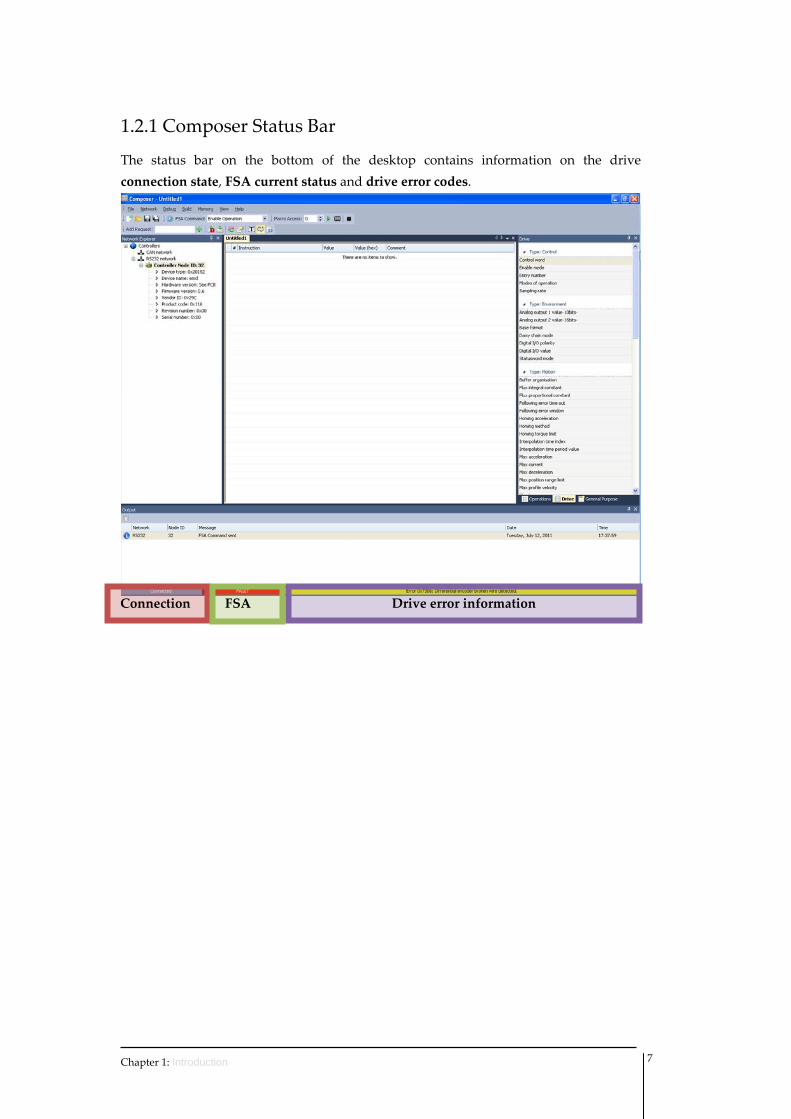
1.2.1 Composer Status Bar
The status bar on the bottom of the desktop contains information on the drive connection state, FSA current status and drive error codes.
Drive error informationFSA Connection
Chapter 1: Introduction 7
2 Connecting to the Drive
In order to download user macros to the Drive, a connection between Composer and Servo Drive needs to be performed. Composer software allows for that connection either through RS232 interface or through CAN/CANopen interface. Before proceeding with the connection, you must accomplish the following actions: ‐ If you are working in a CANopen network, make sure that the required CAN
board(s) have been successfully installed. ‐ Proper cabling your computer’s serial or CAN port to the drive. ‐ Proper wire the Drive to the motor and feedbacks. ‐ Provide electrical power to the Drive.
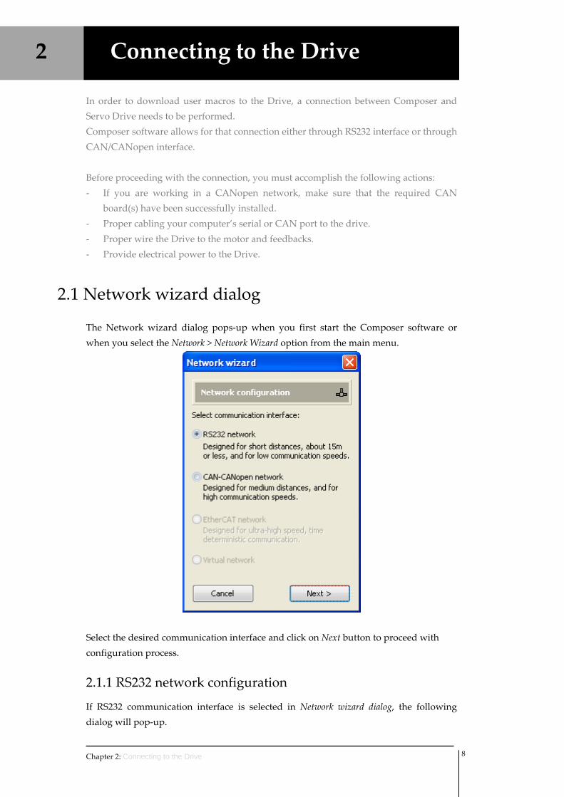
2.1 Network wizard dialog
The Network wizard dialog pops‐up when you first start the Composer software or when you select the Network > Network Wizard option from the main menu.
Select the desired communication interface and click on Next button to proceed with configuration process.
2.1.1 RS232 network configuration
If RS232 communication interface is selected in Network wizard dialog, the following dialog will pop‐up.
Chapter 2: Connecting to the Drive 8
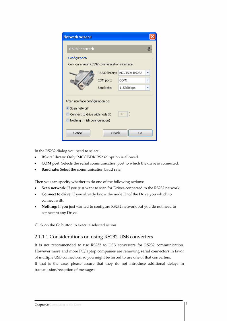
In the RS232 dialog you need to select: • RS232 library: Only ‘MCCISDK RS232’ option is allowed. • COM port: Selects the serial communication port to which the drive is connected. • Baud rate: Select the communication baud rate. Then you can specify whether to do one of the following actions: • Scan network: If you just want to scan for Drives connected to the RS232 network. • Connect to drive: If you already know the node ID of the Drive you which to
connect with. • Nothing: If you just wanted to configure RS232 network but you do not need to
connect to any Drive. Click on the Go button to execute selected action.
2.1.1.1 Considerations on using RS232‐USB converters It is not recommended to use RS232 to USB converters for RS232 communication. However more and more PC/laptop companies are removing serial connectors in favor of multiple USB connectors, so you might be forced to use one of that converters. If that is the case, please assure that they do not introduce additional delays in transmission/reception of messages.
Chapter 2: Connecting to the Drive 9
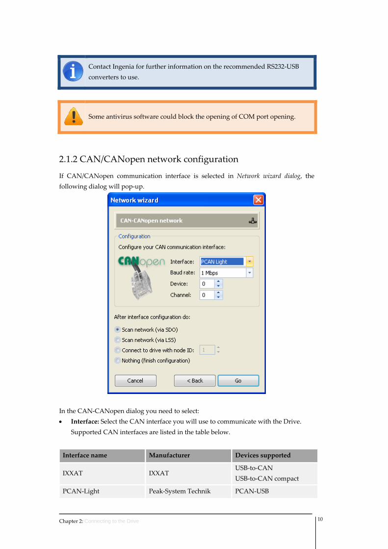
Contact Ingenia for further information on the recommended RS232‐USB converters to use.
Some antivirus software could block the opening of COM port opening.
2.1.2 CAN/CANopen network configuration
If CAN/CANopen communication interface is selected in Network wizard dialog, the following dialog will pop‐up.
In the CAN‐CANopen dialog you need to select: • Interface: Select the CAN interface you will use to communicate with the Drive.
Supported CAN interfaces are listed in the table below.
Interface name Manufacturer Devices supported
IXXAT IXXAT USB‐to‐CAN USB‐to‐CAN compact
PCAN‐Light Peak‐System Technik PCAN‐USB
Chapter 2: Connecting to the Drive 10
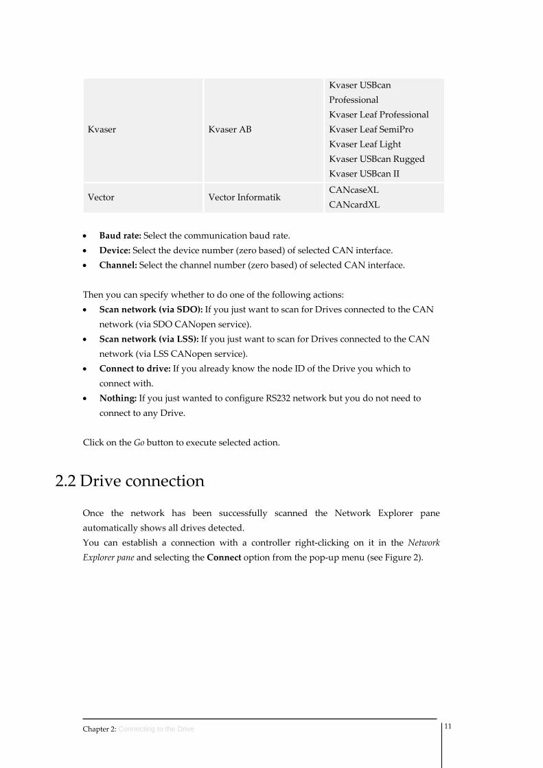
Kvaser Kvaser AB
Kvaser USBcan Professional Kvaser Leaf Professional Kvaser Leaf SemiPro Kvaser Leaf Light Kvaser USBcan Rugged Kvaser USBcan II
Vector Vector Informatik CANcaseXL CANcardXL
• Baud rate: Select the communication baud rate. • Device: Select the device number (zero based) of selected CAN interface. • Channel: Select the channel number (zero based) of selected CAN interface. Then you can specify whether to do one of the following actions: • Scan network (via SDO): If you just want to scan for Drives connected to the CAN
network (via SDO CANopen service). • Scan network (via LSS): If you just want to scan for Drives connected to the CAN
network (via LSS CANopen service). • Connect to drive: If you already know the node ID of the Drive you which to
connect with. • Nothing: If you just wanted to configure RS232 network but you do not need to
connect to any Drive. Click on the Go button to execute selected action.
2.2 Drive connection
Once the network has been successfully scanned the Network Explorer pane automatically shows all drives detected. You can establish a connection with a controller right‐clicking on it in the Network Explorer pane and selecting the Connect option from the pop‐up menu (see Figure 2).
Chapter 2: Connecting to the Drive 11
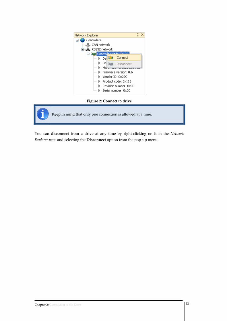
Figure 2: Connect to drive
Keep in mind that only one connection is allowed at a time.
You can disconnect from a drive at any time by right‐clicking on it in the Network Explorer pane and selecting the Disconnect option from the pop‐up menu.
Chapter 2: Connecting to the Drive 12
3 Drive State
Current state of Drives connected to Composer software can be checked at any time in the status bar at the bottom of the desktop. Transition events to switch from one state to another one can be sent using Control toolbar functions.
3.1 Finite state automaton
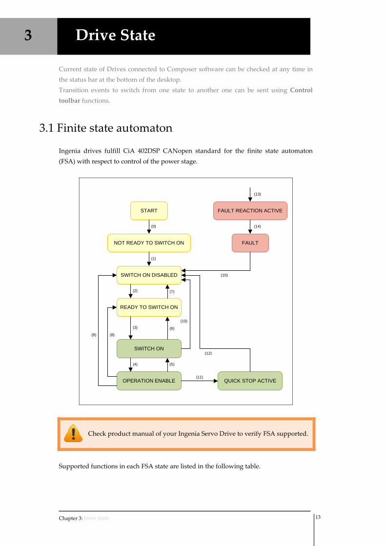
Ingenia drives fulfill CiA 402DSP CANopen standard for the finite state automaton (FSA) with respect to control of the power stage.
START
NOT READY TO SWITCH ON
(0)
SWITCH ON DISABLED
READY TO SWITCH ON
(2)
FAULT
(1)
FAULT REACTION ACTIVE
(14)
(15)
SWITCH ON
OPERATION ENABLE QUICK STOP ACTIVE
(4) (5)
(6)(3)
(7)
(11)
(8)(9)
(10)
(12)
(13)
Check product manual of your Ingenia Servo Drive to verify FSA supported.
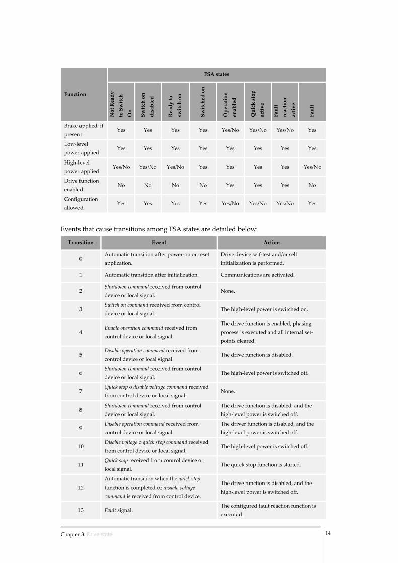
Supported functions in each FSA state are listed in the following table.
Chapter 3: Drive state 13
Function
FSA states
Not Ready
to Switch
On
Switch on
disabled
Ready to
switch on
Switched on
Operation
enabled
Quick stop
active
Fault
reaction
active
Fault
Brake applied, if present
Yes Yes Yes Yes Yes/No Yes/No Yes/No Yes
Low‐level power applied
Yes Yes Yes Yes Yes Yes Yes Yes
High‐level power applied
Yes/No Yes/No Yes/No Yes Yes Yes Yes Yes/No
Drive function enabled
No No No No Yes Yes Yes No
Configuration allowed
Yes Yes Yes Yes Yes/No Yes/No Yes/No Yes
Events that cause transitions among FSA states are detailed below:
Transition Event Action
0 Automatic transition after power‐on or reset application.
Drive device self‐test and/or self initialization is performed.
1 Automatic transition after initialization. Communications are activated.
2 Shutdown command received from control device or local signal.
None.
3 Switch on command received from control device or local signal.
The high‐level power is switched on.
4 Enable operation command received from control device or local signal.
The drive function is enabled, phasing process is executed and all internal set‐points cleared.
5 Disable operation command received from control device or local signal.
The drive function is disabled.
6 Shutdown command received from control device or local signal.
The high‐level power is switched off.
7 Quick stop o disable voltage command received from control device or local signal.
None.
8 Shutdown command received from control device or local signal.
The drive function is disabled, and the high‐level power is switched off.
9 Disable operation command received from control device or local signal.
The driver function is disabled, and the high‐level power is switched off.
10 Disable voltage o quick stop command received from control device or local signal.
The high‐level power is switched off.
11 Quick stop received from control device or local signal.
The quick stop function is started.
12 Automatic transition when the quick stop function is completed or disable voltage command is received from control device.
The drive function is disabled, and the high‐level power is switched off.
13 Fault signal. The configured fault reaction function is executed.
Chapter 3: Drive state 14
Chapter 3: Drive state 15
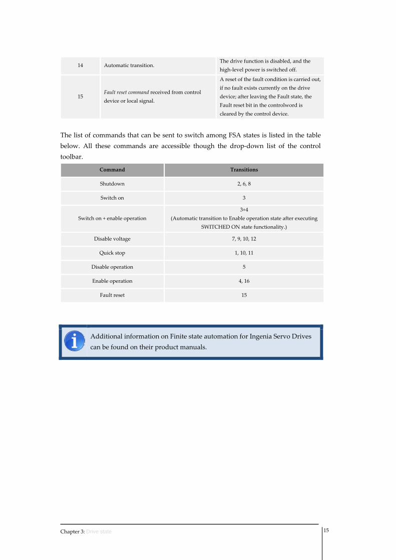
14 Automatic transition. The drive function is disabled, and the high‐level power is switched off.
15 Fault reset command received from control device or local signal.
A reset of the fault condition is carried out, if no fault exists currently on the drive device; after leaving the Fault state, the Fault reset bit in the controlword is cleared by the control device.
The list of commands that can be sent to switch among FSA states is listed in the table below. All these commands are accessible though the drop‐down list of the control toolbar.
Command Transitions
Shutdown 2, 6, 8
Switch on 3
Switch on + enable operation 3+4
(Automatic transition to Enable operation state after executing SWITCHED ON state functionality.)
Disable voltage 7, 9, 10, 12
Quick stop 1, 10, 11
Disable operation 5
Enable operation 4, 16
Fault reset 15
Additional information on Finite state automation for Ingenia Servo Drives can be found on their product manuals.
4 Programming interface
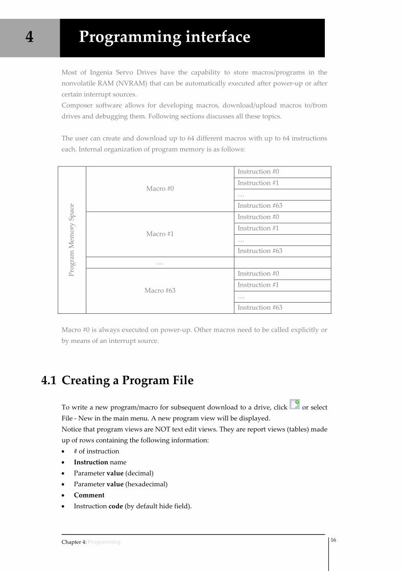
Most of Ingenia Servo Drives have the capability to store macros/programs in the nonvolatile RAM (NVRAM) that can be automatically executed after power‐up or after certain interrupt sources. Composer software allows for developing macros, download/upload macros to/from drives and debugging them. Following sections discusses all these topics. The user can create and download up to 64 different macros with up to 64 instructions each. Internal organization of program memory is as follows:
Prog
ram M
emory Sp
ace
Macro #0
Instruction #0 Instruction #1 … Instruction #63
Macro #1
Instruction #0 Instruction #1 … Instruction #63
…
Macro #63
Instruction #0 Instruction #1 … Instruction #63
Macro #0 is always executed on power‐up. Other macros need to be called explicitly or by means of an interrupt source.
4.1 Creating a Program File
To write a new program/macro for subsequent download to a drive, click or select File ‐ New in the main menu. A new program view will be displayed. Notice that program views are NOT text edit views. They are report views (tables) made up of rows containing the following information: • # of instruction • Instruction name • Parameter value (decimal) • Parameter value (hexadecimal) • Comment • Instruction code (by default hide field).
Chapter 4: Programming 16
4.1.1 Adding instructions
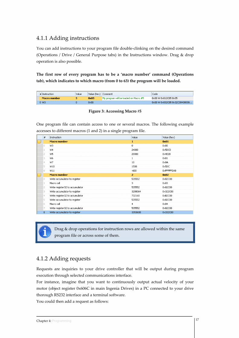
You can add instructions to your program file double‐clinking on the desired command (Operations / Drive / General Purpose tabs) in the Instructions window. Drag & drop operation is also possible. The first row of every program has to be a ‘macro number’ command (Operations tab), which indicates to which macro (from 0 to 63) the program will be loaded.
Figure 3: Accessing Macro #5 One program file can contain access to one or several macros. The following example accesses to different macros (1 and 2) in a single program file.
Drag & drop operations for instruction rows are allowed within the same program file or across some of them.
4.1.2 Adding requests
Requests are inquiries to your drive controller that will be output during program execution through selected communications interface. For instance, imagine that you want to continuously output actual velocity of your motor (object register 0x606C in main Ingenia Drives) in a PC connected to your drive thorough RS232 interface and a terminal software. You could then add a request as follows:
Chapter 4: Programming 17
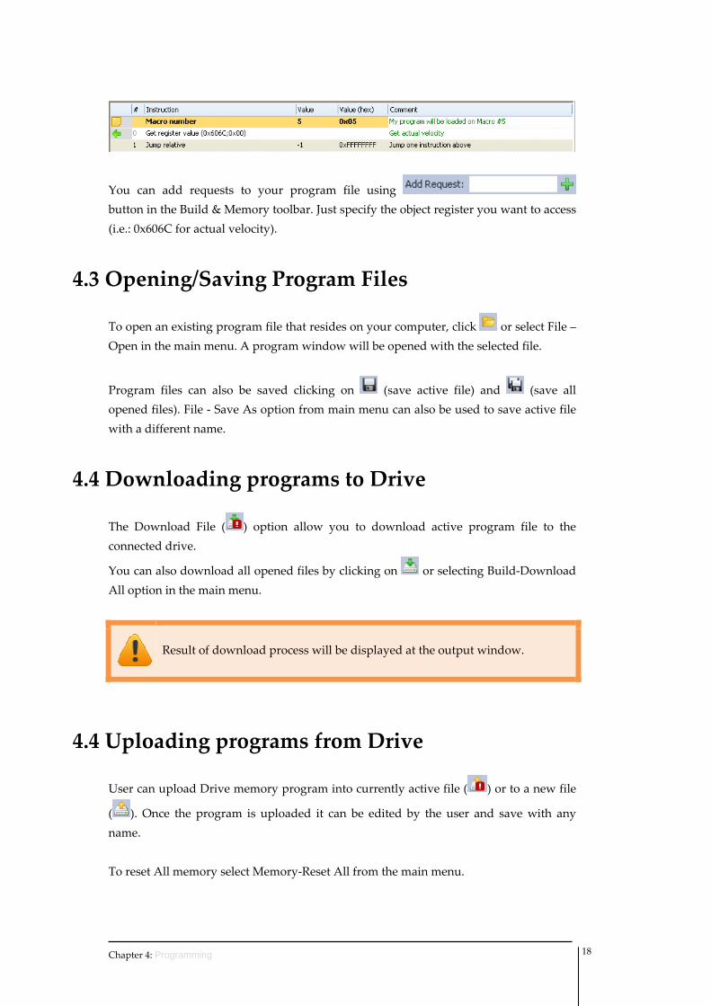
You can add requests to your program file using button in the Build & Memory toolbar. Just specify the object register you want to access (i.e.: 0x606C for actual velocity).
4.3 Opening/Saving Program Files
To open an existing program file that resides on your computer, click or select File – Open in the main menu. A program window will be opened with the selected file.
Program files can also be saved clicking on (save active file) and (save all opened files). File ‐ Save As option from main menu can also be used to save active file with a different name.
4.4 Downloading programs to Drive
The Download File ( ) option allow you to download active program file to the connected drive.
You can also download all opened files by clicking on or selecting Build‐Download All option in the main menu.
Result of download process will be displayed at the output window.
4.4 Uploading programs from Drive
User can upload Drive memory program into currently active file ( ) or to a new file
( ). Once the program is uploaded it can be edited by the user and save with any name. To reset All memory select Memory‐Reset All from the main menu.
Chapter 4: Programming 18
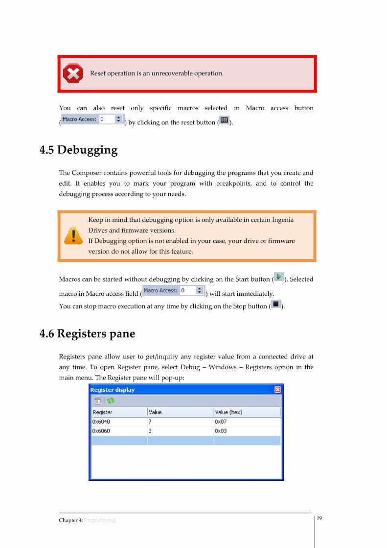
Reset operation is an unrecoverable operation.
You can also reset only specific macros selected in Macro access button
( ) by clicking on the reset button ( ).
4.5 Debugging
The Composer contains powerful tools for debugging the programs that you create and edit. It enables you to mark your program with breakpoints, and to control the debugging process according to your needs.
Keep in mind that debugging option is only available in certain Ingenia Drives and firmware versions. If Debugging option is not enabled in your case, your drive or firmware version do not allow for this feature.
Macros can be started without debugging by clicking on the Start button ( ). Selected
macro in Macro access field ( ) will start immediately.
You can stop macro execution at any time by clicking on the Stop button ( ).
4.6 Registers pane
Registers pane allow user to get/inquiry any register value from a connected drive at any time. To open Register pane, select Debug – Windows – Registers option in the main menu. The Register pane will pop‐up:
Chapter 4: Programming 19
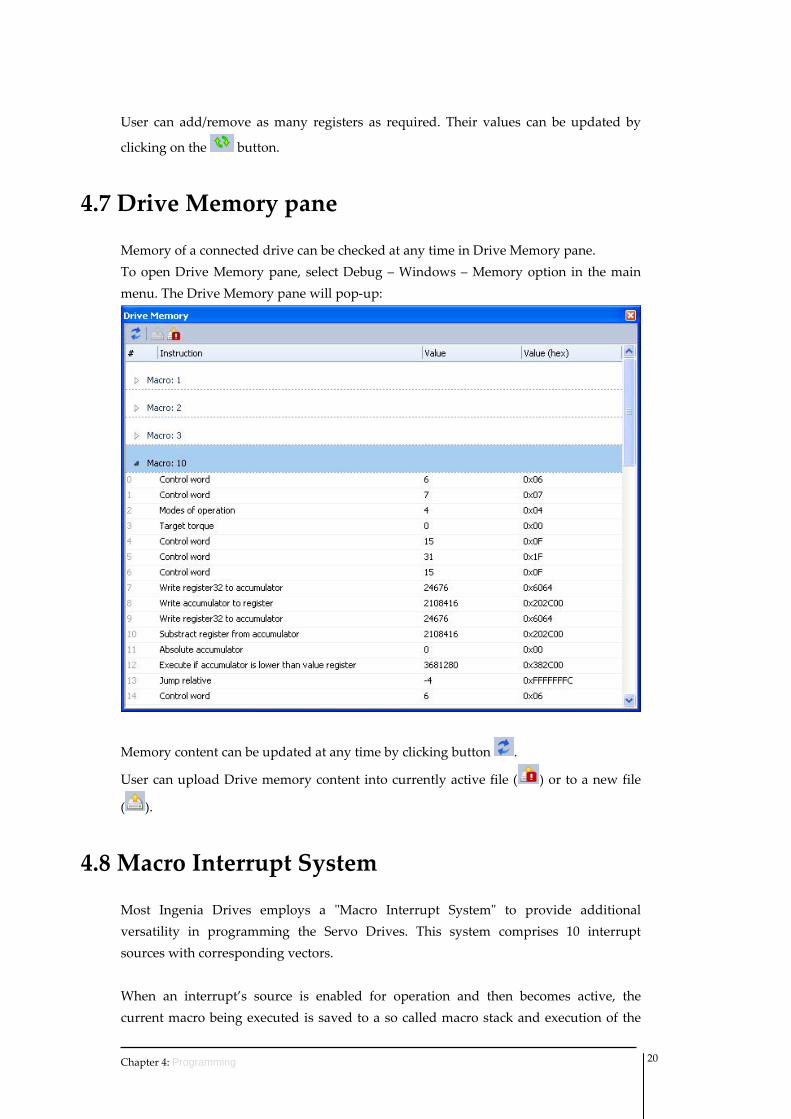
User can add/remove as many registers as required. Their values can be updated by
clicking on the button.
4.7 Drive Memory pane
Memory of a connected drive can be checked at any time in Drive Memory pane. To open Drive Memory pane, select Debug – Windows – Memory option in the main menu. The Drive Memory pane will pop‐up:
Memory content can be updated at any time by clicking button .
User can upload Drive memory content into currently active file ( ) or to a new file
( ).
4.8 Macro Interrupt System
Most Ingenia Drives employs a ʺMacro Interrupt Systemʺ to provide additional versatility in programming the Servo Drives. This system comprises 10 interrupt sources with corresponding vectors. When an interrupt’s source is enabled for operation and then becomes active, the current macro being executed is saved to a so called macro stack and execution of the
Chapter 4: Programming 20
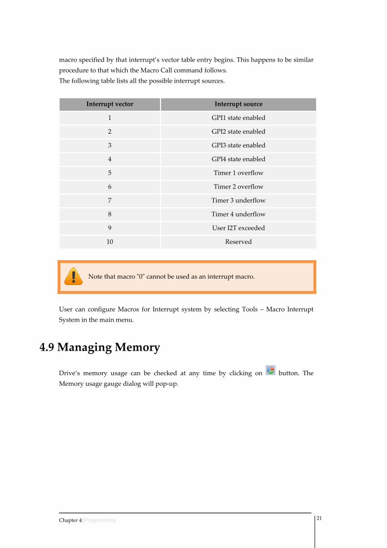
macro specified by that interrupt’s vector table entry begins. This happens to be similar procedure to that which the Macro Call command follows. The following table lists all the possible interrupt sources.
Interrupt vector Interrupt source
1 GPI1 state enabled
2 GPI2 state enabled
3 GPI3 state enabled
4 GPI4 state enabled
5 Timer 1 overflow
6 Timer 2 overflow
7 Timer 3 underflow
8 Timer 4 underflow
9 User I2T exceeded
10 Reserved
Note that macro ʺ0ʺ cannot be used as an interrupt macro.
User can configure Macros for Interrupt system by selecting Tools – Macro Interrupt System in the main menu.
4.9 Managing Memory
Drive’s memory usage can be checked at any time by clicking on button. The Memory usage gauge dialog will pop‐up.
Chapter 4: Programming 21
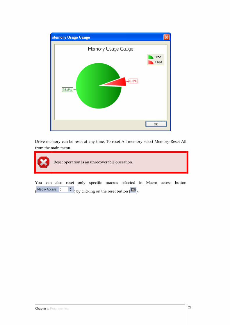
Drive memory can be reset at any time. To reset All memory select Memory‐Reset All from the main menu.
Reset operation is an unrecoverable operation.
You can also reset only specific macros selected in Macro access button
( ) by clicking on the reset button ( ).
Chapter 4: Programming 22
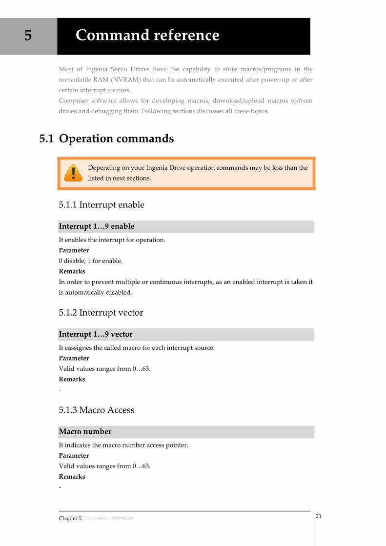
5 Command reference
Most of Ingenia Servo Drives have the capability to store macros/programs in the nonvolatile RAM (NVRAM) that can be automatically executed after power‐up or after certain interrupt sources. Composer software allows for developing macros, download/upload macros to/from drives and debugging them. Following sections discusses all these topics.
5.1 Operation commands
Depending on your Ingenia Drive operation commands may be less than the listed in next sections.
5.1.1 Interrupt enable
Interrupt 1…9 enable
It enables the interrupt for operation. Parameter 0 disable, 1 for enable. Remarks In order to prevent multiple or continuous interrupts, as an enabled interrupt is taken it is automatically disabled.
5.1.2 Interrupt vector
Interrupt 1…9 vector
It eassignes the called macro for each interrupt source. Parameter Valid values ranges from 0…63. Remarks ‐
5.1.3 Macro Access
Macro number
It indicates the macro number access pointer. Parameter Valid values ranges from 0…63. Remarks ‐
Chapter 5: Command Reference 23
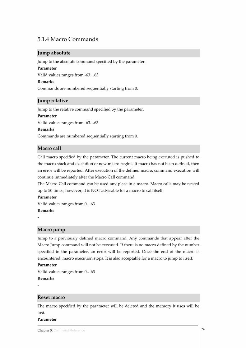
5.1.4 Macro Commands
Jump absolute
Jump to the absolute command specified by the parameter. Parameter Valid values ranges from ‐63…63. Remarks Commands are numbered sequentially starting from 0.
Jump relative
Jump to the relative command specified by the parameter. Parameter Valid values ranges from ‐63…63 Remarks Commands are numbered sequentially starting from 0.
Macro call
Call macro specified by the parameter. The current macro being executed is pushed to the macro stack and execution of new macro begins. If macro has not been defined, then an error will be reported. After execution of the defined macro, command execution will continue immediately after the Macro Call command. The Macro Call command can be used any place in a macro. Macro calls may be nested up to 50 times; however, it is NOT advisable for a macro to call itself. Parameter Valid values ranges from 0…63 Remarks ‐
Macro jump
Jump to a previously defined macro command. Any commands that appear after the Macro Jump command will not be executed. If there is no macro defined by the number specified in the parameter, an error will be reported. Once the end of the macro is encountered, macro execution stops. It is also acceptable for a macro to jump to itself. Parameter Valid values ranges from 0…63 Remarks ‐
Reset macro
The macro specified by the parameter will be deleted and the memory it uses will be lost. Parameter
Chapter 5: Command Reference 24
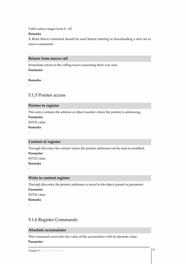
Valid values ranges from 0…63 Remarks A Reset Macro command should be used before entering or downloading a new set of macro commands.
Return from macro call
Immediate return to the calling macro (assuming there was one). Parameter ‐ Remarks ‐
5.1.5 Pointer access
Pointer to register
This entry contains the address or object number where the pointer is addressing. Parameter INT32 value Remarks ‐
Content of register
Through this entry the content where the pointer addresses can be read or modified. Parameter INT32 value Remarks ‐
Write to content register
Through this entry the pointer addresses is saved in the object passed as parameter. Parameter INT32 value Remarks ‐
5.1.6 Register Commands
Absolute accumulator
This command overwrites the value of the accumulator with its absolute value. Parameter
Chapter 5: Command Reference 25
‐ Remarks ‐
Accumulator complement
This command overwrites the value of the accumulator with its absolute value. Parameter ‐ Remarks ‐
Accumulator divide constant
This command performs a 64 bit by 32 bit signed division with a 64 bit quotient and a 32 bit remainder. The low order 32 bits of the numerator must be in the accumulator and the high order 32 bits must be in W2. The divisor is specified by the value passed as a parameter. The lower 32 bits of the quotient will be stored in the accumulator and the upper 32 bits will be stored in W2. Parameter INT32 value Remarks ‐
Accumulator divide register
This command performs a 64 bit by 32 bit signed division with a 64 bit quotient and a 32 bit remainder. The low order 32 bits of the numerator must be in the accumulator and the high order 32 bits must be in W2. The divisor is the content of the register specified by the parameter. The lower 32 bits of the quotient will be stored in the accumulator and the upper 32 bits will be stored in W2. Parameter Register Remarks ‐
Accumulator multiply constant
This command does a signed multiply of the 32 bit contents of the accumulator and by the value passed to the object, leaving the lower 32 bits of the 64 bit product in the accumulator and the upper 32 bits in W2. Parameter INT32 value Remarks ‐
Chapter 5: Command Reference 26
Accumulator multiply register
This command does a signed multiply of the 32 bit contents of the accumulator and by the content of the register specified by the value, leaving the lower 32 bits of the 64 bit product in the accumulator and the upper 32 bits in W2. Parameter Register Remarks ‐
Add constant to accumulator
This command adds the 32bit signed value passed as parameter to the accumulator. Parameter INT32 value Remarks ‐
Add register to accumulator
This command adds the content of the indicated register to the accumulator. Parameter Register Remarks ‐
And constant to accumulator
This command causes the result of a 32bits AND of the accumulator with the value passed as a parameter to reside in the accumulator. Parameter INT32 value Remarks ‐
And register to accumulator
This command causes the result of the accumulator ANDed with the content of the register specified by the parameter to reside in the accumulator. Parameter Register Remarks ‐
Or constant to accumulator
This command causes the result of a 32bits OR of the accumulator with the value passed as a parameter to reside in the accumulator.
Chapter 5: Command Reference 27
Parameter INT32 value Remarks ‐
Or register to accumulator
This command causes the result of an OR of the accumulator with the content of the register specified by the parameter to reside in the accumulator. Parameter Register Remarks ‐
Shift left accumulator by constant
This command causes the accumulator to be shifted left the number of bits indicated by the value while filling the low order bits with zero. Parameter INT32 value Remarks ‐
Shift left accumulator by register
This command causes the accumulator to be shifted left the number of bits indicated by the content of the register specified by the parameter while filling the low order bits with zero. Parameter Register Remarks ‐
Shift right accumulator by constant
This command causes the accumulator to be shifted right the number of bits indicated by the value while filling high low order bits with zero. Parameter INT32 value Remarks ‐
Shift right accumulator by register
This command causes the accumulator to be shifted right the number of bits indicated by the content of the register specified by the parameter while filling high low order bits with zero.
Chapter 5: Command Reference 28
Parameter Register Remarks ‐
Substract constant from accumulator
This command substrate the 32bit signed value passed as a parameter from the accumulator. Parameter INT32 value Remarks ‐
Substract register from accumulator
This object subtracts the register’s content specified by the parameter to the accumulator. Parameter Register Remarks ‐
Write accumulator to register
This command copies the value of the accumulator into the content of the register passed as a parameter. Parameter Register Remarks ‐
Write register16 to accumulator
This command copies the content of a 16 bit register passed as a parameter into the accumulator. Parameter 16 bit register Remarks ‐
Write register32 to accumulator
This command copies the content of a 32 bit register passed as a parameter into the accumulator. Parameter 32 bit register
Chapter 5: Command Reference 29
Remarks ‐
XOR constant to accumulator
This command causes the result of a 32bits exclusive‐OR of the accumulator with the value passed as a parameter to reside in the accumulator. Parameter INT32 value Remarks ‐
XOR register to accumulator
This command causes the result of an exclusive‐OR of the accumulator with the content of the register specified by the parameter to reside in the accumulator. Parameter Register Remarks ‐
5.1.7 Sequence Commands
Do if input is Off
This command will cause command execution to continue if input channel ‘n’ specified as parameter is ʺOffʺ; otherwise, the rest of the macro will be skipped. Parameter Input channel ‘n’ Remarks The channel used will correspond directly to the General input pin (i.e. if we want to use the general digital input number 1 we must use the channel 1, for input number 2 we will use channel 2 and so on).
Do if input is On
This command will cause command execution to continue if input channel ‘n’ specified as parameter is ʺOnʺ; otherwise, the rest of the macro will be skipped. Parameter Input channel ‘n’ Remarks The channel used will correspond directly to the General input pin (i.e. if we want to use the general digital input number 1 we must use the channel 1, for input number 2 we will use channel 2 and so on).
End Program
Chapter 5: Command Reference 30
This command will cause program execution to cease. Parameter ‐ Remarks ‐
Execute if accumulator bit is clear
If bit ‘n’ of the accumulator (specified in the parameter) is clear (equals 0), macro execution will continue; otherwise, the next command in the macro will be skipped. Parameter Bit of the accumulator to check. Remarks ‐
Execute if accumulator bit is set
If bit ‘n’ of the accumulator (specified in the parameter) is set (equals 1), macro execution will continue; otherwise, the next command in the macro will be skipped. Parameter Bit of the accumulator to check. Remarks ‐
Execute if accumulator is below
If the content of the accumulator is less than (signed comparison) the parameter value, macro execution will continue; otherwise, the next command in the macro will be skipped. Parameter INT32 value Remarks ‐
Execute if accumulator is below than value register
If the content of the accumulator is less than (signed comparison) the content of the register indicated by the parameter, macro execution will continue; otherwise, the next command in the macro will be skipped. Parameter Register Remarks ‐
Execute if accumulator is equal
Chapter 5: Command Reference 31

If the content of the accumulator is equal than (signed comparison) the parameter value, macro execution will continue; otherwise, the next command in the macro will be skipped. Parameter INT32 value Remarks ‐
Execute if accumulator is equal value register
If the content of the accumulator is equal than (signed comparison) the content of the register indicated by the parameter, macro execution will continue; otherwise, the next command in the macro will be skipped. Parameter Register Remarks ‐
Execute if accumulator is higher
If the contents of the accumulator is higher than (signed comparison) the parameter value, macro execution will continue; otherwise, the next command in the macro will be skipped. Parameter INT32 value Remarks ‐
Execute if accumulator is higher than value register
If the contents of the accumulator is higher than (signed comparison) the content of the register indicated by the parameter, macro execution will continue; otherwise, the next command in the macro will be skipped. Parameter Register Remarks ‐
Execute if accumulator is unequal
If the contents of the accumulator is unequal than (signed comparison) the past value, macro execution will continue; otherwise, the next command in the macro will be skipped. Parameter INT32 value Remarks
Chapter 5: Command Reference 32
‐
Execute if accumulator is unequal value register
If the contents of the accumulator is unequal than (signed comparison) the content of the register indicated by the parameter, macro execution will continue; otherwise, the next command in the macro will be skipped. Parameter Register Remarks ‐
Execute if analog 1 is below
If the content of the analog input 1 is lower than (signed comparison) the parameter value, macro execution will continue; otherwise, the next command in the macro will be skipped. Parameter INT32 value Remarks ‐
Execute if analog 1 is higher
If the content of the analog input 1 is higher than (signed comparison) the parameter value, macro execution will continue; otherwise, the next command in the macro will be skipped. Parameter INT32 value Remarks ‐
Execute if input is Off
If the input channel ‘n’ specified as parameter is in the ʺOffʺ state, macro execution will continue; otherwise, the next command in the macro will be skipped. Parameter Input channel ‘n’ Remarks The channel used will correspond directly to the General input pin (i.e. if we want to use the general digital input number 1 we must use the channel 1, for input number 2 we will use channel 2 and so on).
Execute if input is On
If the input channel ‘n’ specified as parameter is in the ʺOnʺ state, macro execution will continue; otherwise, the next command in the macro will be skipped.
Chapter 5: Command Reference 33
Parameter Input channel ‘n’ Remarks The channel used will correspond directly to the General input pin (i.e. if we want to use the general digital input number 1 we must use the channel 1, for input number 2 we will use channel 2 and so on).
Repeat instruction
This command causes the macro to be repeated the number of times specified by of the parameter. If parameter is ʺ0ʺ, the macro is repeated indefinitely. Parameter INT32 value Remarks ‐
Wait (milliseconds)
This command causes a wait period of the parameter‘s content expressed in milliseconds before going on to the next command. Parameter Time to wait in milliseconds Remarks ‐
Wait (milliseconds) register
This command causes a wait period of the register‘s content expressed in milliseconds before going on to the next command. Parameter Register containing wait time (in milliseconds) Remarks ‐
Wait for input to be Off
This command waits until input channel ‘n’ specified as parameter is in the ʺOffʺ state before continuing command execution. Parameter Input channel ‘n’ Remarks The channel used will correspond directly to the General input pin (i.e. if we want to use the general digital input number 1 we must use the channel 1, for input number 2 we will use channel 2 and so on).
Wait for input to be On
Chapter 5: Command Reference 34
This command waits until input channel ‘n’ specified as parameter is in the ʺOnʺ state before continuing command execution. Parameter Input channel ‘n’ Remarks The channel used will correspond directly to the General input pin (i.e. if we want to use the general digital input number 1 we must use the channel 1, for input number 2 we will use channel 2 and so on).
Wait for index
This command will wait for the occurrence of an Index input signal before continuing to the next command. Parameter ‐ Remarks ‐
5.1.8 Timers access
Timer 1 (count up) value
Real timer counter. The value of the timer is incremented every 1 ms until it reaches its maximum value and then is reset to zero. Parameter UINT32 value Remarks ‐
Timer 2 (count up) value
Real timer counter. The value of the timer is incremented every 1 ms until it reaches its maximum value and then is reset to zero. Parameter UINT32 value Remarks ‐
Timer 3 (count down) value
Real timer counter. The value of the timer is decremented every 1 ms until it reaches its minimum value and then is reset to maximum value. Parameter UINT32 value Remarks ‐
Chapter 5: Command Reference 35
Chapter 5: Command Reference 36
Timer 4 (count down) value
Real timer counter. The value of the timer is decremented every 1 ms until it reaches its minimum value and then is reset to maximum value. Parameter UINT32 value Remarks ‐
5.2 Drive commands
Drive commands accessible by the user vary depending on the Ingenia Servo Drive used. All commands correspond to specific object in the Drive Object Dictionary and can be consulted in the programming manual of the Drive.
5.3 General purpose registers commands
Ingenia’s Drives include access to a general purpose RAM memory space that could be used to store temporally parameters, to perform operations, etc. The access is done through working registers whose size is an INTEGER32. There are a total of 100 registers available. First one is called Accumulator (ACCUM) and the next ones are called Wx.
Accumulator (ACCUM)
This command will set value for wait for Accumulator register. Parameter New INT32 value for accumulator Remarks ‐
Wx
This command will set a new value for Wx register. Parameter New INT32 value for Wx general purpose register Remarks ‐