Embed Size (px)
Citation preview
ENGINEERING THE SPACE BELOW
TERMINAL 5Terminal 5 at London’s Heathrow Airport has been the largest
building project in Europe over the past few years, with a
construction bill of nearly £4.3 billion for the British Airports
Authority (BAA). The immense size of the structures and their
basements posed significant challenges for both BAA’s designers
and constructors. These included excavation in London clay and
tunnelling around both existing infrastructure and under the
world’s busiest airport. Mott MacDonald’s Haresh Shanghavi, Jim
Beveridge, Arthur Darby and Alan Powderham FREng explain the
engineering solutions that have helped deliver T5 to time and
within budget, ready for its opening on 27 March 2008.
London Heathrow Airport,
owned and operated by BAA
plc, is the busiest international
airport in the world. Today,
Heathrow handles 67 million
passengers a year, but its original
four-terminal infrastructure was
designed for far less. When the
new Terminal 5 development
opens to the travelling public in
March 2008 it will be one of the
world’s most advanced airport
terminals and will increase the
airport’s passenger capacity to
up to 95 million passengers a
year.
Above ground, Heathrow’s
Terminal 5 embraces design and
architecture at its best while
below ground it hides one of
the most notable engineering
achievements of its kind
anywhere in the world.
The three buildings that
make up Terminal 5 have a
combined floor area greater
than all the other Heathrow
terminals added together. The
main terminal building, called
T5A, and one of two satellite
buildings, T5B, are now complete
(see the map overleaf for the
airport layout). The substructure
of satellite T5C is in place and its
superstructure will be ready for
use by 2010.
The sheer size of the
buildings, particularly the
main one, is clear from the
aerial views. These buildings
are above large underground
structures – the basements,
foundations and tunnels
essential to the operation of
the terminal – the total ground
volume of which, like an iceberg,
greatly exceeds that of the
visible superstructures.
HIDDEN DEPTHS Nearly a fifth of the construction
budget went underground. The
main T5 basement volume is
believed to be the greatest-ever
excavated in the UK – and one
of the deepest. Its plan area is
396 m by 176 m (equivalent to
60 football pitches) and its depth
of 22 m would hold an eight-
Heathrow’s T5A basement contains five floor levels, including baggage storage, handling and reclaim facilities. The baggage system is the biggest single-terminal baggage handling system in Europe, containing 18 km of belts and capable of transporting 12,000 bags per hour around the terminal © David Levene 2008
12 INGENIA ISSUE 34 MARCH 2008 INGENIA ISSUE 34 MARCH 2008 13
ENGINEERING THE SPACE BELOW TERMINAL 5 WEALTH CREATION
14 INGENIA ISSUE 34 MARCH 2008 INGENIA ISSUE 34 MARCH 2008 15
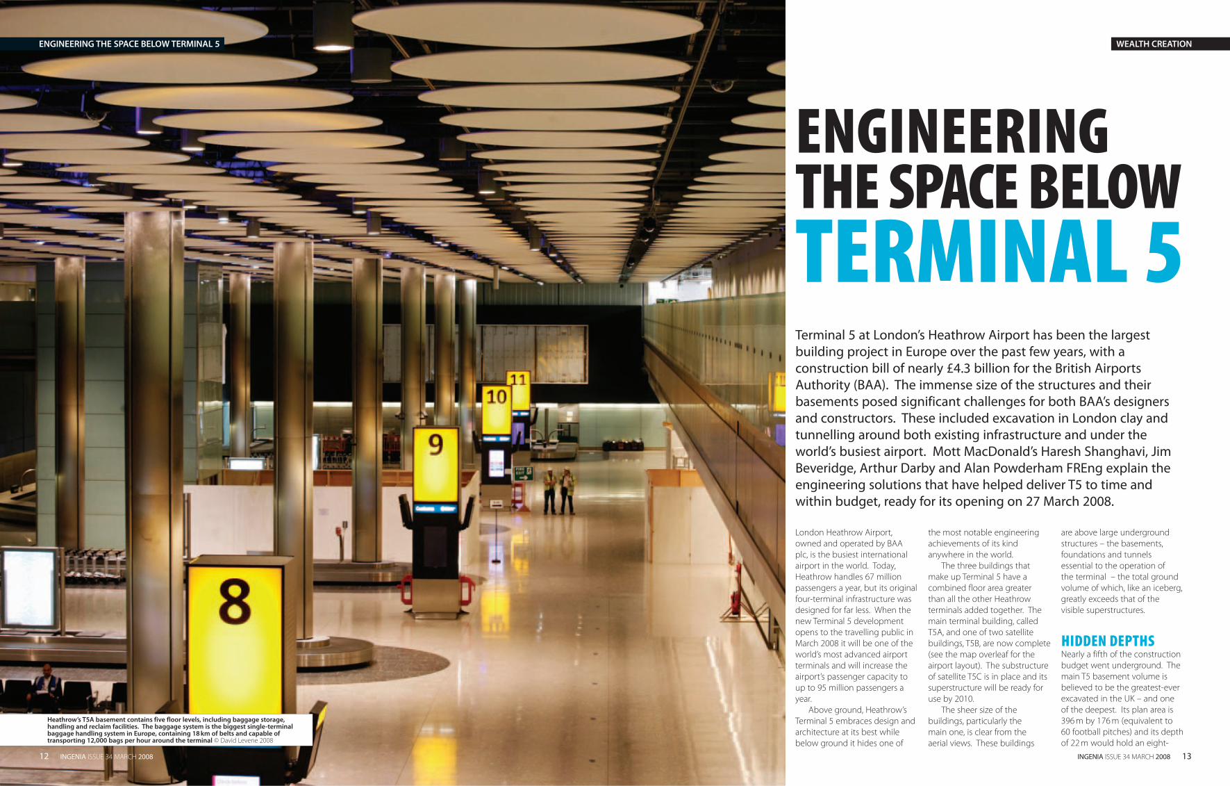
The airport layout
storey building. The foundations
for T5B and C, although much
smaller, are substantial works in
their own right.
A complex unseen network
of road, rail, baggage, passenger
transit and drainage tunnels
has been created close to and
underneath the new terminal
buildings and beneath the
airport’s taxiways and aprons (the
areas where aircraft are parked).
These include extensions to the
Heathrow Express and London
Underground Piccadilly Line rail
tunnels, the airside road tunnel,
stormwater outfall tunnel and
a light rail passenger transit
tunnel connecting the three
terminal buildings. Each tunnel
represented a significant project
in itself.
BAA, the client, developed
and followed a strategy for
managing the construction
and the many contractors and
suppliers needed to complete
T5. This overarching strategy
and the benefits it stimulated are
summarised in the box labelled
'BAA's construction strategy and
their team for these works‘.
For the work described here
– the creation and use of
underground space – the critical
factor was the ground in which
basements were excavated,
foundations installed and
tunnels advanced.
THE GROUND AND ITS BEHAVIOURThe T5 underground structures
are all set within London clay,
a particularly challenging
material in which to dig and
construct. London clay is an
overconsolidated material.
Aeons ago it was thickly covered
in deposits that compressed it,
making it stiff and impermeable.
The clay resists further
compression under loading.
Below a depth of about 50 m
this clay gives way to substantial
amounts of water-bearing silt
and sand.
When the clay is unloaded by
deep excavations compressive
stress is relieved and it expands.
In the deep T5 excavations, the
small immediate rebound of
approximately 50 mm would be
Existing Heathrow Express
Terminal 1
Terminal 2
Terminal 3
PicEx Junction
Existing Piccadilly
Line
PicEx westboundPicEx
eastboundHexEx upline
HexEx downline
T5 Station
Track transit system
T5AT5B T5C
Baggage tunnel Airside road
Storm water outfall tunnel
A3044 services tunnel
M25 Spur
Airside road tunnel
Baggage handling
tunnelTerminal 4
A4
M25
J14
A3113
River Colne
The T5 site is located between Heathrow’s two runways on land previously occupied by a sludge works. The project has successfully moved nine million cubic metres of earth and two rivers have been diverted to create space for the new building © Mott MacDonald
WEALTH CREATIONENGINEERING THE SPACE BELOW TERMINAL 5
16 INGENIA ISSUE 34 MARCH 2008 INGENIA ISSUE 34 MARCH 2008 17
‘lost’ in the excavation process.
That is not the end of the story,
however, as this material then
continues to swell, producing
significant uplift at the surface
– as much as 250 mm within
50 years or so.
If the total load of the
building and basement matches
or exceeds the weight of soil
excavated, this uplift can be
prevented. However, this was
not going to happen at T5, and
had several major implications.
Swelling clay would try to lift
up foundation piles. A floor
slab directly on the clay would
be lifted and lateral stresses
would affect side walls. The
stress-field around an existing
tunnel would change rapidly at
first and then more slowly with
time, depending on how close
it is to the excavation. For new
tunnels, swelling could result in
distortion with implications for
track alignment, ride quality and
even safety.
So our challenges were clear:
when building T5’s five new
tunnels, with their combined
length of some 14 km, we
needed to ensure the swelling
effects of London clay would not
affect these tunnels or the new
tunnels being developed.
When creating the huge
basements of T5 and its satellites,
we had to ensure the natural
swelling of the ground beneath
the basements was controlled
in a way that avoided short-
term and long-term hazard, not
only to the new above-surface
structures, but also to existing
and new tunnels.
COUNTERING SWELLING CLAYFor basement construction,
swelling ground can be handled
in two ways. A massive slab can
be cast directly on the ground
and anchored with very long
piles to resist uplift. Alternatively,
the base slab can be formed
above the ground supported
by piles but leaving a void
beneath, into which the ground
is allowed to swell. The first is a
heavy option with large material
requirements and higher
construction costs. The second
method is far more economical
and BAA selected it, but it did
involve a more complex design.
Foundations had to support
the base slab and terminal
superstructure while resisting
the swelling clay acting to push
the piles upwards.
To complicate the task still
further, different basement levels
offered varying amounts of
unloading and potential swell.
Added to this were different
structural loads which meant
the amounts of force exerted
on the piles would differ. Pile
sizes therefore varied as did
the behaviour of those piles in
contact with swelling clay and
the foundation design needed
to balance these opposing
forces (see the box opposite).
SUPPORTING THE SUPERSTRUCTUREA pile’s load-bearing capacity is obtained from adhesion to the
ground around it. The greater the surface area of the pile, the more
is its friction with the surrounding soil and from the transmission of
load through its base to the ground beneath it. Thus the larger the
pile diameter, the greater the load it can carry but the greater too is
the uplift force from the swelling.
The foundation design also had to ensure excessive ground
movement would not affect the terminal building superstructure.
T5 has a grid of columns at 18 m centres supporting concourse
floors. The columns rise from a base slab founded on principal and
intermediate piles on a 9 m grid. Differential movement between
piles would be translated to the columns – as one moved relative to
its neighbours, stress would be introduced to the beams supporting
the terminal building’s floors. The maximum allowable movement
over the length of beams was 1:500, meaning a differential
movement of 36 mm over 18 m.
FOUNDATION PILINGAt the first design stage, we initially thought the foundation piles
would be constructed as open bores of up to 2.1 m diameter
without any support to the pile wall before concreting. The sandy
water-bearing zones at the base of the London clay, however,
meant these piles could be no deeper than 50 m. To increase load
capacity, piles with enlarged bases up to 6m in diameter, called
under-reamed piles, could be used but their installation is both
slower than conventional bored piling and susceptible to the risk of
collapse. The indication was that about 450 of the building’s 1,100
piles would be under-reamed.
Extensive instrumented, full-scale pile testing of research quality
and detailed analysis enabled us to reduce the number of under-
reamed piles by 90%. This brought a 30% cut in the volume of
concrete and savings in construction time. Project safety was
improved by less need for under-reaming. We then applied these
lessons from the foundation design of T5A to T5B and C, which
needed 326 piles each.
Geological profile of the T5 site
Swelling
forces
London
clay 45m
Load from building superstructure
Base slab
22m
18m
Straight
shafted pile,
2.1m diameter
Pile with 6m
diameter
underream
Terrace
gravels 5m
Granular water-bearing material
RECYCLING UNDERGROUNDThe water table across the T5 site was only 3 m below the surface
when construction commenced. To enable deep basements to
be excavated without filling with water an extensive system of
boreholes was installed in advance of the main works to draw
down the water table. With construction complete, BAA is
continuing to use the boreholes to tap ground water. This will
be augmented by recycled rainwater which drains from across
the T5 campus via the stormwater outfall tunnel to a lagoon.
Groundwater and rainwater will be used for flushing toilets
and watering planted areas, reducing T5’s reliance on the mains
water supply by 70%.
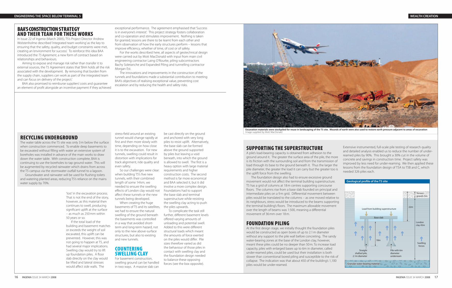
Excavation materials were stockpiled for reuse in landscaping of the T5 site. Mounds of earth were also used to restore earth pressure adjacent to areas of excavation Image supplied by Mott MacDonald
ENGINEERING THE SPACE BELOW TERMINAL 5 WEALTH CREATION
BAA’S CONSTRUCTION STRATEGY AND THEIR TEAM FOR THESE WORKS In Issue 22 of Ingenia (March 2005), T5’s Project Director Andrew
Wolstenholme described ‘integrated team working’ as the key to
ensuring that the safety, quality, and budget constraints were met,
creating an ‘environment for success’. To reinforce this idea BAA
introduced the T5 Agreement, a new form of contract based on
relationships and behaviours.
Aiming to expose and manage risk rather than transfer it to
external sources, the T5 Agreement states that ‘BAA holds all the risk
associated with the development. By removing that burden from
the supply chain, suppliers can work as part of the integrated team
and can focus on delivery of the project.’
BAA also promised to reimburse suppliers’ costs and guarantee
an element of profit alongside an incentive payment if they achieved
exceptional performance. The agreement emphasised that ‘Success
is in everyone’s interest’. This project strategy fosters collaboration
and co-operation and stimulates improvement. Nothing is taken
for granted; lessons are there to be learnt from each other and
from observation of how the early structures perform – lessons that
improve efficiency, whether of time, of cost or of safety.
For the works described here, all aspects of geotechnical design
were carried out by Mott MacDonald with input from main civil
engineering contractor Laing O’Rourke, piling subcontractors
Bachy Soletanche and Expanded Piling and tunnelling contractor
Morgan Est.
The innovations and improvements in the construction of the
tunnels and foundations made a substantial contribution to meeting
BAA’s objectives of realising exceptional value, preventing cost
escalation and by reducing the health and safety risks.

18 INGENIA ISSUE 34 MARCH 2008 INGENIA ISSUE 34 MARCH 2008 19
AIRSIDE ROAD TUNNELAt 8.8 m diameter and 1.3 km
in length this twin bore airside
road tunnel is the largest of the
five new T5 tunnels and required
particularly delicate tunnelling.
It crosses the existing Piccadilly
Line tunnel with 3 m clearance
and the Heathrow Express tunnel
with 5 m clearance. Excessive
movement of either existing
tunnel would endanger railway
operation and potentially force
suspension of services. The
airside road tunnel also passes
beneath taxiways. Ground
movement resulting from
tunnelling had to be limited
to ensure the safety of BAA’s
operations.
To overcome this, the vertical
and horizontal alignment of the
airside road tunnel was fine-
tuned to minimise the influence
of tunnelling. In plan, the tunnel
is curved to avoid taxiways and
apron areas as far as possible,
while in profile it undulates.
Near their portals the twin
bores of the airside road tunnel
are extremely shallow. Risk
assessments showed a danger
of settlement if excavation
broke out of the stable London
clay stratum into the overlying
gravel layer. So the gravel within
2 m of the tunnel crown was
removed near the portals before
tunnelling started and replaced
with concrete.
A bespoke earth pressure
balance tunnel boring machine
was designed to minimise
ground movement, allowing
pressure to be maintained on
the tunnel face even while the
ground was being gouged
away. We closely monitored
settlement during excavation
by instrumentation in the rail
tunnels and on the surface, with
surveys for distortion.
AIRSIDE ROAD TUNNEL PORTALSAt the airside road tunnel
portals the transition from
tunnel to ground level is
made in cut-and-cover boxes.
Here we constructed piled
walls, excavated the ground
between the walls and then
constructed base and roof slabs.
Conventionally piled walls like
these would be propped with
massive temporary steel struts
to resist overturning forces as
excavation advanced. However,
analysis of the piles plus our
carefully planned construction
methodology meant we could
eliminate the struts, saving
31 weeks on the excavation
programme and greatly
reducing safety risks inherent in
handling temporary steel struts.
Temporary support was
provided at intermediate levels
as work advanced by pouring
concrete slabs directly onto the
base of the excavation – the
slabs acted as struts. They
were progressively broken out
as excavation to full depth
advanced and the permanent
base slab was cast.
If movement was detected,
additional slabs could quickly be
installed to provide support and
prevent excessive deformation.
A special concrete mix that
cured and provided strength
quickly was designed for the
job. In practice, no unplanned
propping was needed.
EXCAVATING THE T5C BASEMENT T5 relies on tunnels of many
types, sizes and purposes to
function. The alignments of
14k m of new tunnels were
dictated by the need for the
stations to be close to the
arrivals and departure halls, by
the locations of existing tunnels
and by the constraints of the site
itself, which is boxed in by the
M25 motorway and Heathrow’s
north and south runways.
By the time the foundations
of T5C came to be built the
tunnels were already in place.
The basement excavation was
therefore just a few metres away
from the new underground
structures of the Piccadilly Line
and Heathrow Express – a mere
3 m in the latter case. This
nearness meant swelling of the
clay would affect the tunnels,
with potentially destabilising
effects. This could happen in
various ways.
BALANCING PRESSURESWe designed a construction
sequence for the foundations
that ensures the least ground
movement or structural
displacements. The design
included establishing ‘trigger
levels’ of key parameters at
particular locations, particularly
of displacement, at which pre-
planned mitigating measures
would be initiated to control,
and if appropriate, halt further
movement. We surveyed
movement sensors in the tunnels
in real time during excavation of
the foundations and throughout
the construction process – none
of the trigger levels was reached.
We excavated the basement
in stages rather than across
the whole area to minimise
the amount of unloading at
any one time. Excavated soil
was mounded temporarily on
previously excavated areas to
maintain load, and then tunnel
spoil was re-used as fill on the
T5 site.
At the critical location where
the crown of the Heathrow
Express tunnel is only 3 m below
the excavation base we installed
massive holding-down beams
connected to anchor piles to
span across this section rather
like giant staples.
NEW TUNNELSFive new tunnels now serve
Terminal 5. Existing twin
bore tunnels for London
Underground’s Piccadilly Line
and the Heathrow Express rail
link were extended by 1.7 km
and 1.6 km respectively. A
new, 1.3 km-long, road tunnel
provides airside vehicle access to
T5 from the rest of the Heathrow
complex, crossing above both
Piccadilly Line and Heathrow
Express tunnels and beneath
taxiways. A 4.1k m, 3 m diameter
stormwater outfall tunnel
removes rainwater runoff from
the airport area and incorporates
four 20 m deep shafts. Also,
new passenger track transit and
baggage transfer tunnels link all
three T5 buildings.
We considered ground
movements arising from
tunnelling to be among the
major risks because of the
way they could damage
existing infrastructure and
disrupt rail services or airport
operations. So monitoring and
control of ground movement
became a key part of our risk
management strategy. While
most tunnelling has used tunnel
boring machines, innovative
developments meant that a
single shell shotcrete lined
tunnelling method, Lasershell
(see overleaf ), was used to build
the many short, complex tunnels
associated with the main bores.
Heathrow Express
TunnelRail
TunnelRoad
Tunnel
West
PortalEast
Portal
Thames
Gravel
London
Clay
0 100 500 1000 1300Distance (metres)
30
20
10
0
Dep
th (m
etre
s)
Plan on airside road tunnel
Delivery of rolling stock for the track transit system that connects T5A, B and C © www.baa.com/photolibrary
Cross section of the Airside Road Tunnel © Mott MacDonald
ARCHAEOLOGYFollowing a programme of
rescue archaeology, a team
of around 80 archaeologists
began excavations in April
2002. To help facilitate this, a
post-excavation department
including relevant
equipment and computer
facilities was established on
site. To date over 80,000
artefacts have been found,
including 18,000 pieces of
pottery and 40,000 pieces
of worked flint. There is a
dedicated website showing
the results of these digs and
a history of the area at
www.framearch.co.uk/t5
ENGINEERING THE SPACE BELOW TERMINAL 5 WEALTH CREATION
Traffic
envelope
Segmental
concrete lining
8.10m I.DE & M Services
in Tunnel crown
Tunnel
Drainage
Flexible
Pavement
Granular Fill
Cable Ducts
(in concrete
surround)
20 INGENIA ISSUE 34 MARCH 2008 INGENIA ISSUE 34 MARCH 2008 21
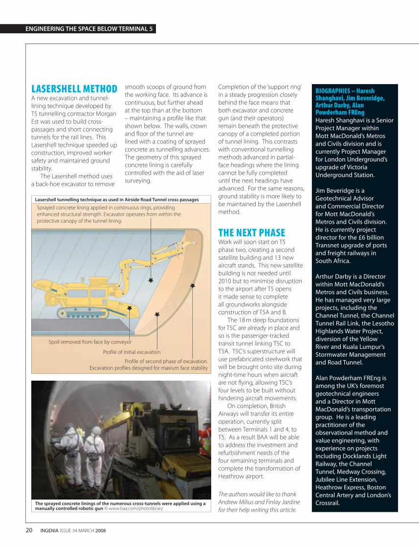
LASERSHELL METHODA new excavation and tunnel-
lining technique developed by
T5 tunnelling contractor Morgan
Est was used to build cross-
passages and short connecting
tunnels for the rail lines. This
Lasershell technique speeded up
construction, improved worker
safety and maintained ground
stability.
The Lasershell method uses
a back-hoe excavator to remove
smooth scoops of ground from
the working face. Its advance is
continuous, but further ahead
at the top than at the bottom
– maintaining a profile like that
shown below. The walls, crown
and floor of the tunnel are
lined with a coating of sprayed
concrete as tunnelling advances.
The geometry of this sprayed
concrete lining is carefully
controlled with the aid of laser
surveying.
Completion of the ‘support ring’
in a steady progression closely
behind the face means that
both excavator and concrete
gun (and their operators)
remain beneath the protective
canopy of a completed portion
of tunnel lining. This contrasts
with conventional tunnelling
methods advanced in partial-
face headings where the lining
cannot be fully completed
until the next headings have
advanced. For the same reasons,
ground stability is more likely to
be maintained by the Lasershell
method.
THE NEXT PHASEWork will soon start on T5
phase two, creating a second
satellite building and 13 new
aircraft stands. This new satellite
building is not needed until
2010 but to minimise disruption
to the airport after T5 opens
it made sense to complete
all groundworks alongside
construction of T5A and B.
The 18 m deep foundations
for T5C are already in place and
so is the passenger-tracked
transit tunnel linking T5C to
T5A. T5C’s superstructure will
use prefabricated steelwork that
will be brought onto site during
night-time hours when aircraft
are not flying, allowing T5C’s
four levels to be built without
hindering aircraft movements.
On completion, British
Airways will transfer its entire
operation, currently split
between Terminals 1 and 4, to
T5. As a result BAA will be able
to address the investment and
refurbishment needs of the
four remaining terminals and
complete the transformation of
Heathrow airport.
The authors would like to thank
Andrew Milius and Finlay Jardine
for their help writing this article.
BIOGRAPHIES – Haresh Shanghavi, Jim Beveridge, Arthur Darby, Alan Powderham FREngHaresh Shanghavi is a Senior
Project Manager within
Mott MacDonald’s Metros
and Civils division and is
currently Project Manager
for London Underground’s
upgrade of Victoria
Underground Station.
Jim Beveridge is a
Geotechnical Advisor
and Commercial Director
for Mott MacDonald’s
Metros and Civils division.
He is currently project
director for the £6 billion
Transnet upgrade of ports
and freight railways in
South Africa.
Arthur Darby is a Director
within Mott MacDonald’s
Metros and Civils business.
He has managed very large
projects, including the
Channel Tunnel, the Channel
Tunnel Rail Link, the Lesotho
Highlands Water Project,
diversion of the Yellow
River and Kuala Lumpur’s
Stormwater Management
and Road Tunnel.
Alan Powderham FREng is
among the UK’s foremost
geotechnical engineers
and a Director in Mott
MacDonald’s transportation
group. He is a leading
practitioner of the
observational method and
value engineering, with
experience on projects
including Docklands Light
Railway, the Channel
Tunnel, Medway Crossing,
Jubilee Line Extension,
Heathrow Express, Boston
Central Artery and London’s
Crossrail.The sprayed concrete linings of the numerous cross-tunnels were applied using a manually controlled robotic gun © www.baa.com/photolibrary
Lasershell tunnelling technique as used in Airside Road Tunnel cross passages
ENGINEERING THE SPACE BELOW TERMINAL 5
Heathrow’s Terminal 5 is the biggest free standing building
in the UK. The single span wave-shaped roof can be seen
from miles around and inside creates a feeling of light
and space. Dervilla Mitchell FREng led the Arup team and
acted as Head of Design Management for this project. In
this article, she writes about the logistics of building the
Terminal building and installing the new air traffic control
tower.
T5 GOES LIVE
WEALTH CREATION
Terminal 5 will be the new home for BA at Heathrow airport © Arup
Sprayed concrete lining applied in continuous rings, providing
enhanced structural strength. Excavator operates from within the
protective canopy of the tunnel lining.
Spoil removed from face by conveyor
Profile of initial excavation
Profile of second phase of excavation.
Excavation profiles designed for maxium face stability