Embed Size (px)
Citation preview
Completion & Stimulation
Unconventional Reservoirs
ITBA
J. Ponce
Oct 2014

2
Completion & Stimulation Unconventional Reservoirs
Disclaimer, Copyrights & Legal Notice
This presentation is for nonprofit, illustrative and general educational purposes only.
I do not make any warranty, express or implied, or assume any legal liability or responsibility for the accuracy, completeness, or usefulness of any information, apparatus, product, or process disclosed, or represent that its use would not infringe privately owned rights.
Every picture or drawing used to describe a tool or system has been only utilized for illustration purposes and has been properly identified and remains as a property of their respective owners / authors.
Reference herein to any specific commercial product, process, or service by trade name, trademark, manufacturer, or otherwise does not necessarily constitute or imply its endorsement, recommendation, or favoring by myself. The views and opinions of the author expressed herein do not necessarily state or reflect those of the company where the author works for.
Further, while I have taken all reasonable steps to ensure that everything published is accurate I do not accept any responsibility for any errors or resulting loss or damage whatsoever or howsoever caused and readers and practitioners have the responsibility to thoroughly check these aspects for themselves.
This presentation or any of its contents may be reproduced, copied, modified or adapted, subject to inclusion of presentation’s title, author, date and copyright notice of other authors.
3
Completion & Stimulation Unconventional Reservoirs
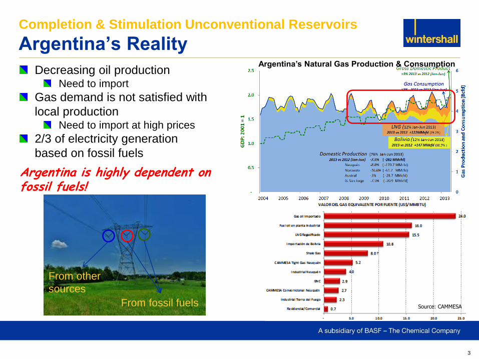
Argentina’s Reality
Source: CAMMESA
Argentina’s Natural Gas Production & Consumption
Argentina is highly dependent on fossil fuels!
Decreasing oil production Need to import
Gas demand is not satisfied with
local production Need to import at high prices
2/3 of electricity generation
based on fossil fuels
From fossil fuels
From other
sources
4
Completion & Stimulation Unconventional Reservoirs
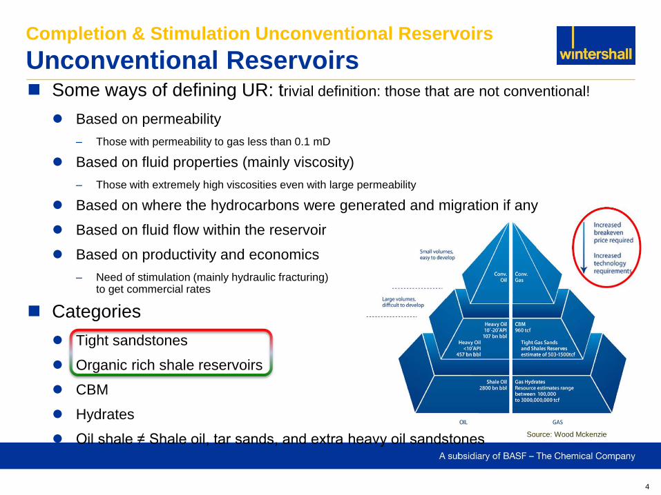
Unconventional Reservoirs Some ways of defining UR: trivial definition: those that are not conventional!
Based on permeability
– Those with permeability to gas less than 0.1 mD
Based on fluid properties (mainly viscosity)
– Those with extremely high viscosities even with large permeability
Based on where the hydrocarbons were generated and migration if any
Based on fluid flow within the reservoir
Based on productivity and economics
– Need of stimulation (mainly hydraulic fracturing) to get commercial rates
Categories
Tight sandstones
Organic rich shale reservoirs
CBM
Hydrates
Oil shale ≠ Shale oil, tar sands, and extra heavy oil sandstones Source: Wood Mckenzie
5
Hydrocarbons are generated, trapped and stored in the same rock
Negligible migration or if any within the reservoir
Definition of word “shale” based on grain size rather than mineralogy composition (rock type)
Shale gas, shale oil. Barnett, Eagleford, Vaca Muerta, Lower Molles
Grains size < 1/256 mm
Low porosity (< 12%) and extremely low permeability. Kv ≈ +/- 0.01 Kh
Fluids go from dry gas to oil
Interest on high API oil as it will be the only one with capacity to flow. High pressure
Rocks go from siltstones to carbonates with variable clay content
Focus on high quartz content, then carbonates. We prefer clays < 30 %
High lamination = issues for frac propagation
Darcy’s flow is the exception rather than the rule
Storage in poral volume, natural fissures, dissolved and adsorbed
Completion & Stimulation Unconventional Reservoirs
Organic Rich Shale Reservoirs
6
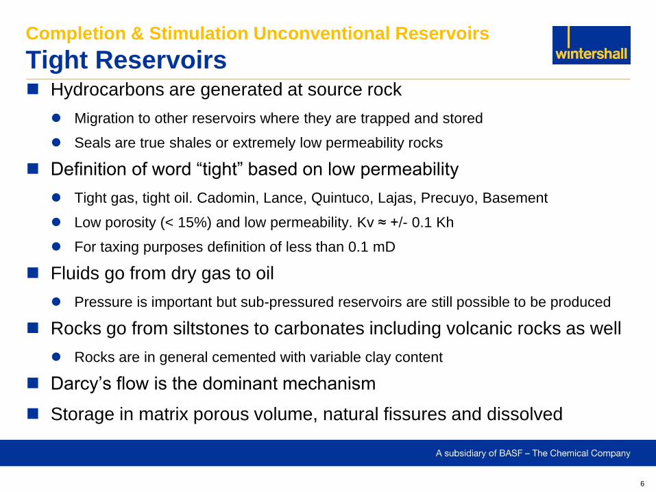
Hydrocarbons are generated at source rock
Migration to other reservoirs where they are trapped and stored
Seals are true shales or extremely low permeability rocks
Definition of word “tight” based on low permeability
Tight gas, tight oil. Cadomin, Lance, Quintuco, Lajas, Precuyo, Basement
Low porosity (< 15%) and low permeability. Kv ≈ +/- 0.1 Kh
For taxing purposes definition of less than 0.1 mD
Fluids go from dry gas to oil
Pressure is important but sub-pressured reservoirs are still possible to be produced
Rocks go from siltstones to carbonates including volcanic rocks as well
Rocks are in general cemented with variable clay content
Darcy’s flow is the dominant mechanism
Storage in matrix porous volume, natural fissures and dissolved
Completion & Stimulation Unconventional Reservoirs
Tight Reservoirs
7
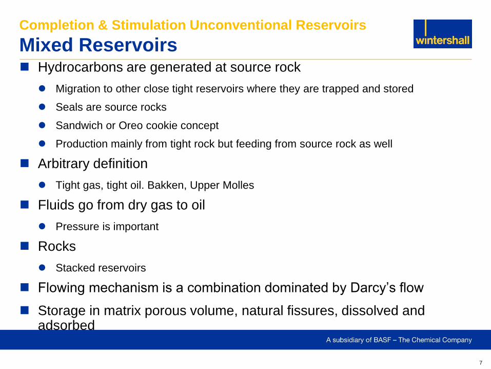
Hydrocarbons are generated at source rock
Migration to other close tight reservoirs where they are trapped and stored
Seals are source rocks
Sandwich or Oreo cookie concept
Production mainly from tight rock but feeding from source rock as well
Arbitrary definition
Tight gas, tight oil. Bakken, Upper Molles
Fluids go from dry gas to oil
Pressure is important
Rocks
Stacked reservoirs
Flowing mechanism is a combination dominated by Darcy’s flow
Storage in matrix porous volume, natural fissures, dissolved and adsorbed
Completion & Stimulation Unconventional Reservoirs
Mixed Reservoirs
8
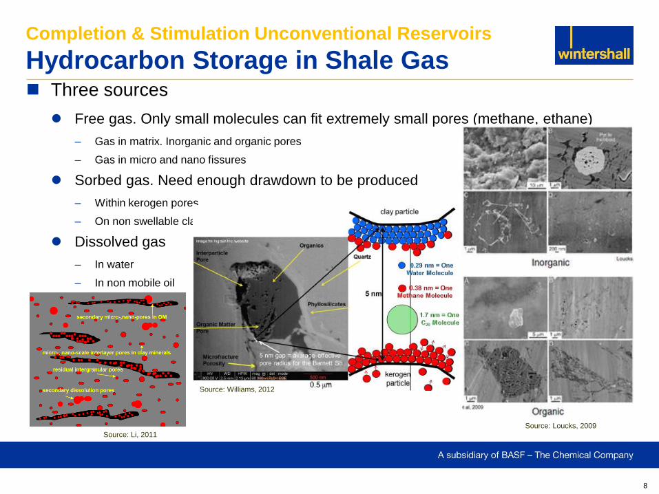
Three sources
Free gas. Only small molecules can fit extremely small pores (methane, ethane)
– Gas in matrix. Inorganic and organic pores
– Gas in micro and nano fissures
Sorbed gas. Need enough drawdown to be produced
– Within kerogen pores
– On non swellable clays
Dissolved gas
– In water
– In non mobile oil
Completion & Stimulation Unconventional Reservoirs
Hydrocarbon Storage in Shale Gas
Source: Li, 2011
Source: Williams, 2012
Source: Loucks, 2009
9
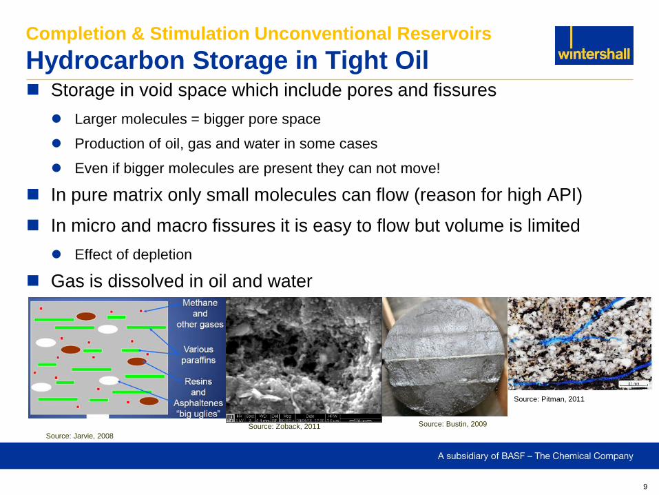
Storage in void space which include pores and fissures
Larger molecules = bigger pore space
Production of oil, gas and water in some cases
Even if bigger molecules are present they can not move!
In pure matrix only small molecules can flow (reason for high API)
In micro and macro fissures it is easy to flow but volume is limited
Effect of depletion
Gas is dissolved in oil and water
Completion & Stimulation Unconventional Reservoirs
Hydrocarbon Storage in Tight Oil
Source: Bustin, 2009 Source: Zoback, 2011
Source: Jarvie, 2008
Source: Pitman, 2011
10
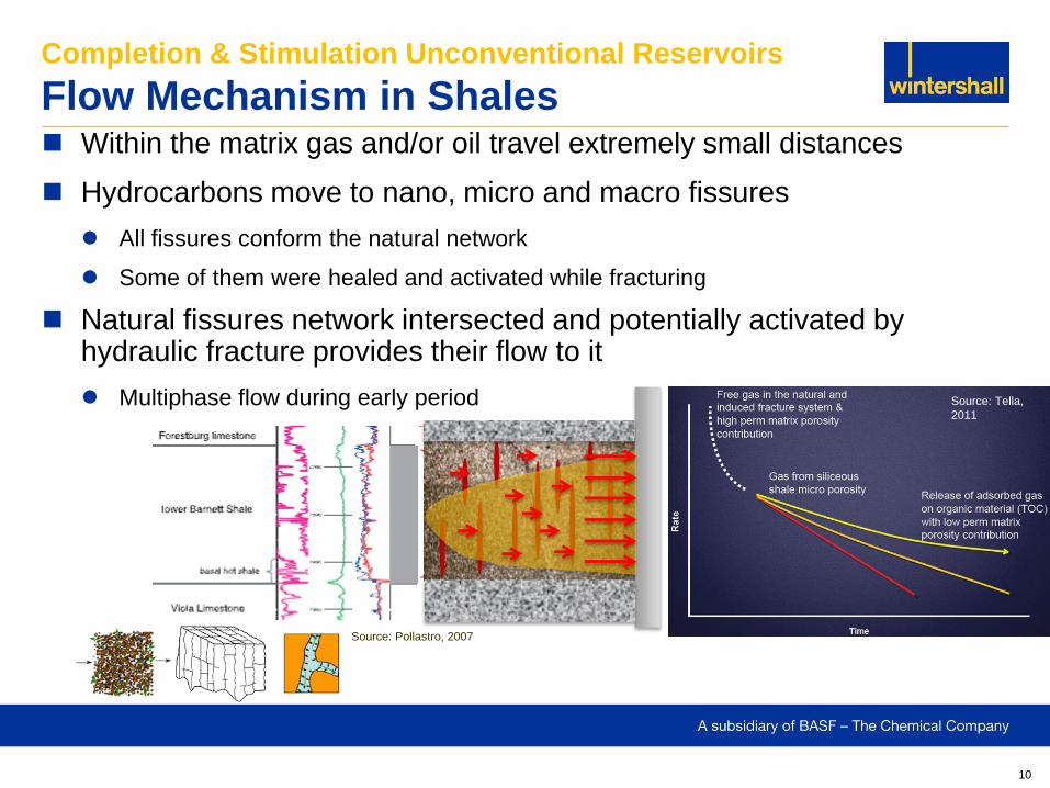
Within the matrix gas and/or oil travel extremely small distances
Hydrocarbons move to nano, micro and macro fissures
All fissures conform the natural network
Some of them were healed and activated while fracturing
Natural fissures network intersected and potentially activated by hydraulic fracture provides their flow to it
Multiphase flow during early period
Completion & Stimulation Unconventional Reservoirs
Flow Mechanism in Shales
Source: Tella,
2011
Source: Pollastro, 2007
11
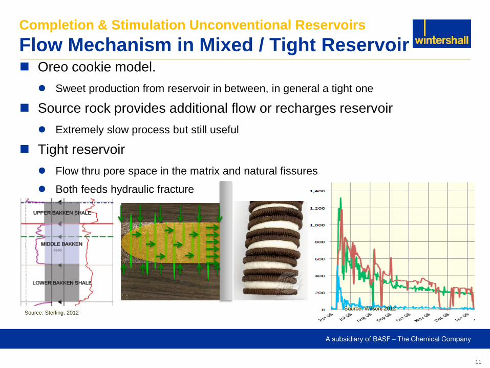
Oreo cookie model.
Sweet production from reservoir in between, in general a tight one
Source rock provides additional flow or recharges reservoir
Extremely slow process but still useful
Tight reservoir
Flow thru pore space in the matrix and natural fissures
Both feeds hydraulic fracture
Completion & Stimulation Unconventional Reservoirs
Flow Mechanism in Mixed / Tight Reservoir
Source: Sterling, 2012 Source: Wilson, 2012
12
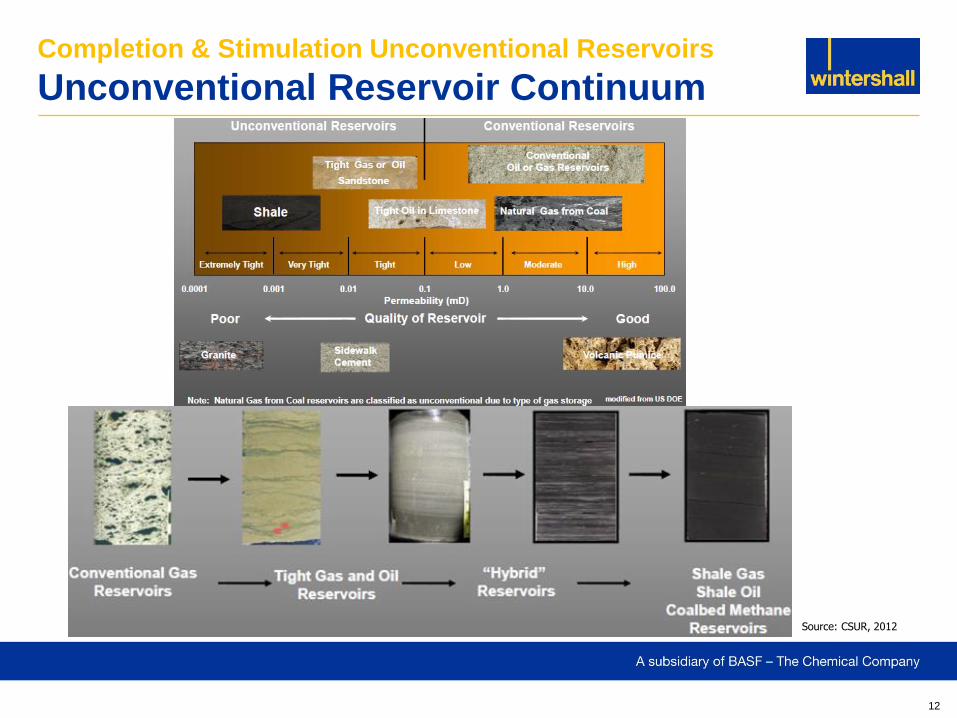
Completion & Stimulation Unconventional Reservoirs
Unconventional Reservoir Continuum
Source: CSUR, 2012
13
Completion & Stimulation Unconventional Reservoirs
Hydrocarbons Types
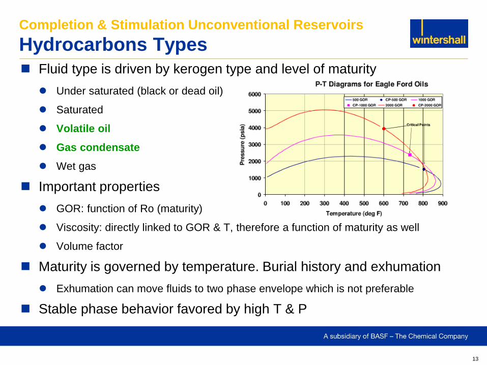
Fluid type is driven by kerogen type and level of maturity
Under saturated (black or dead oil)
Saturated
Volatile oil
Gas condensate
Wet gas
Important properties
GOR: function of Ro (maturity)
Viscosity: directly linked to GOR & T, therefore a function of maturity as well
Volume factor
Maturity is governed by temperature. Burial history and exhumation
Exhumation can move fluids to two phase envelope which is not preferable
Stable phase behavior favored by high T & P
14
Completion & Stimulation Unconventional Reservoirs
Fluid Behavior in Nano-pores
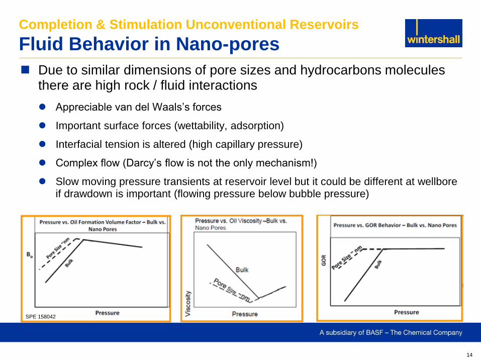
Due to similar dimensions of pore sizes and hydrocarbons molecules there are high rock / fluid interactions
Appreciable van del Waals’s forces
Important surface forces (wettability, adsorption)
Interfacial tension is altered (high capillary pressure)
Complex flow (Darcy’s flow is not the only mechanism!)
Slow moving pressure transients at reservoir level but it could be different at wellbore if drawdown is important (flowing pressure below bubble pressure)
SPE 158042
15
Completion & Stimulation Unconventional Reservoirs
Fluid Behavior in Nano-pores
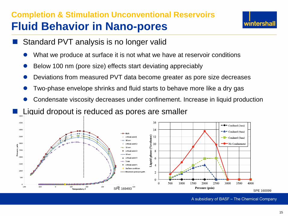
Standard PVT analysis is no longer valid
What we produce at surface it is not what we have at reservoir conditions
Below 100 nm (pore size) effects start deviating appreciably
Deviations from measured PVT data become greater as pore size decreases
Two-phase envelope shrinks and fluid starts to behave more like a dry gas
Condensate viscosity decreases under confinement. Increase in liquid production
Liquid dropout is reduced as pores are smaller
SPE 160099 SPE 169493
16
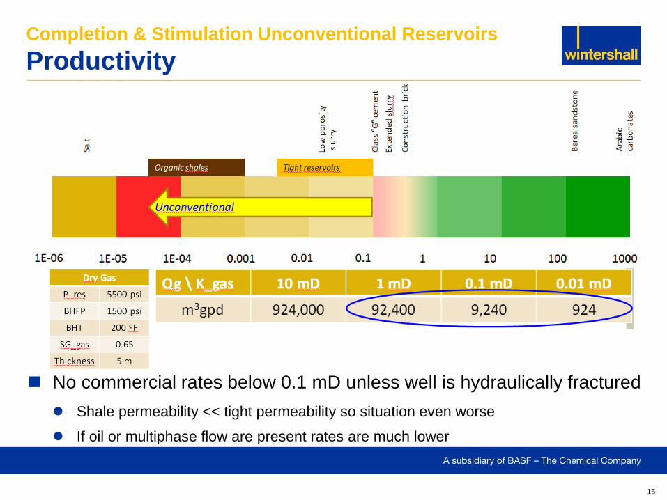
No commercial rates below 0.1 mD unless well is hydraulically fractured
Shale permeability << tight permeability so situation even worse
If oil or multiphase flow are present rates are much lower
Completion & Stimulation Unconventional Reservoirs
Productivity
17
Completion & Stimulation Unconventional Reservoirs
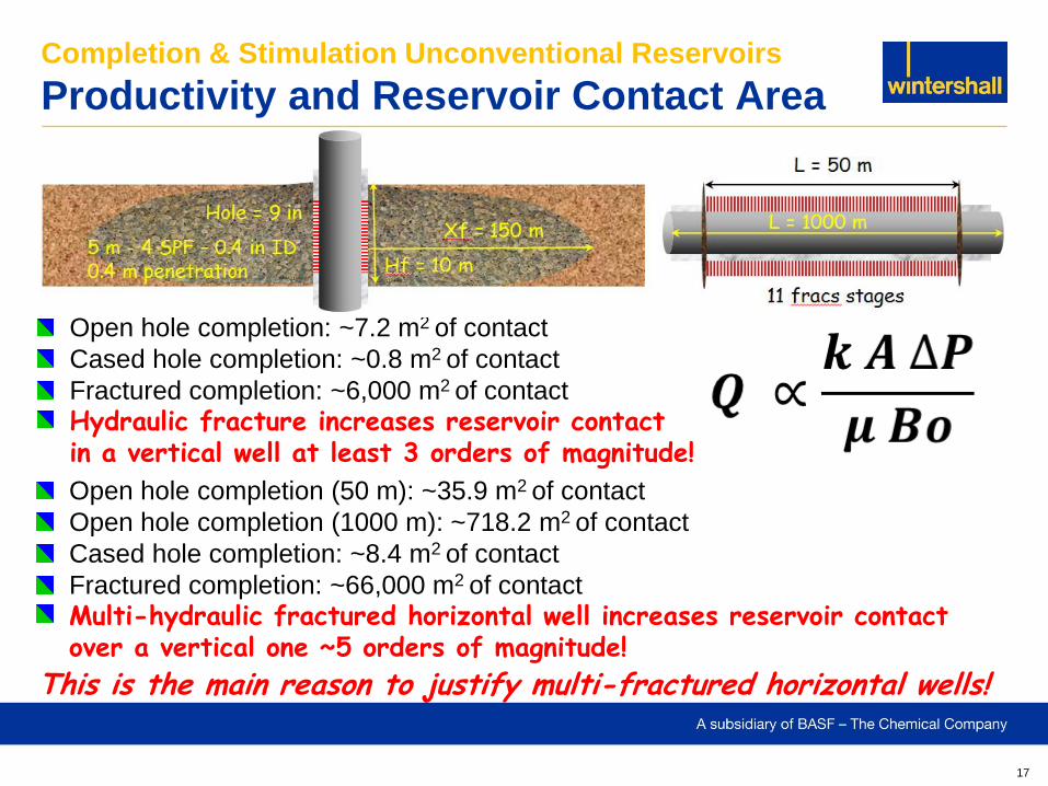
Productivity and Reservoir Contact Area
Open hole completion: ~7.2 m2 of contact
Cased hole completion: ~0.8 m2 of contact
Fractured completion: ~6,000 m2 of contact
Hydraulic fracture increases reservoir contact in a vertical well at least 3 orders of magnitude!
Open hole completion (50 m): ~35.9 m2 of contact
Open hole completion (1000 m): ~718.2 m2 of contact
Cased hole completion: ~8.4 m2 of contact
Fractured completion: ~66,000 m2 of contact
Multi-hydraulic fractured horizontal well increases reservoir contact over a vertical one ~5 orders of magnitude!
11 fracs stages
This is the main reason to justify multi-fractured horizontal wells!
18
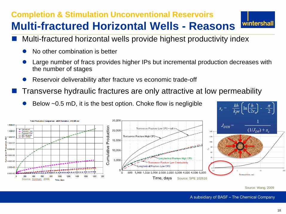
Multi-fractured horizontal wells provide highest productivity index
No other combination is better
Large number of fracs provides higher IPs but incremental production decreases with the number of stages
Reservoir deliverability after fracture vs economic trade-off
Transverse hydraulic fractures are only attractive at low permeability
Below ~0.5 mD, it is the best option. Choke flow is negligible
Completion & Stimulation Unconventional Reservoirs
Multi-fractured Horizontal Wells - Reasons
Source: SPE 102616
Source: Wang, 2009
19
Completion & Stimulation Unconventional Reservoirs
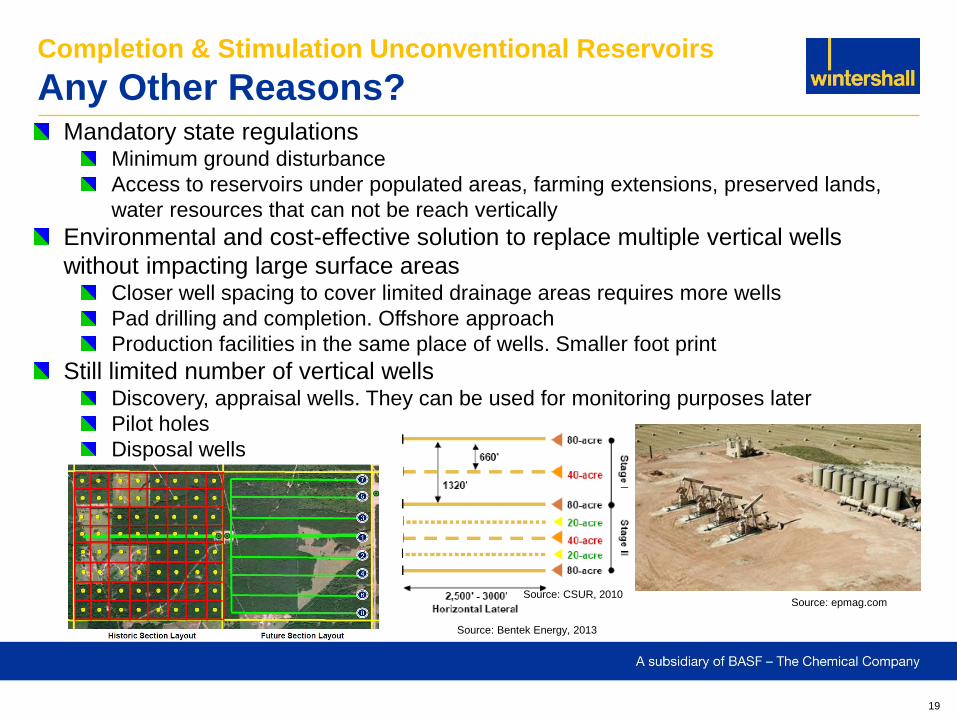
Any Other Reasons? Mandatory state regulations
Minimum ground disturbance
Access to reservoirs under populated areas, farming extensions, preserved lands,
water resources that can not be reach vertically
Environmental and cost-effective solution to replace multiple vertical wells
without impacting large surface areas Closer well spacing to cover limited drainage areas requires more wells
Pad drilling and completion. Offshore approach
Production facilities in the same place of wells. Smaller foot print
Still limited number of vertical wells Discovery, appraisal wells. They can be used for monitoring purposes later
Pilot holes
Disposal wells
Source: Bentek Energy, 2013
Source: epmag.com Source: CSUR, 2010
20
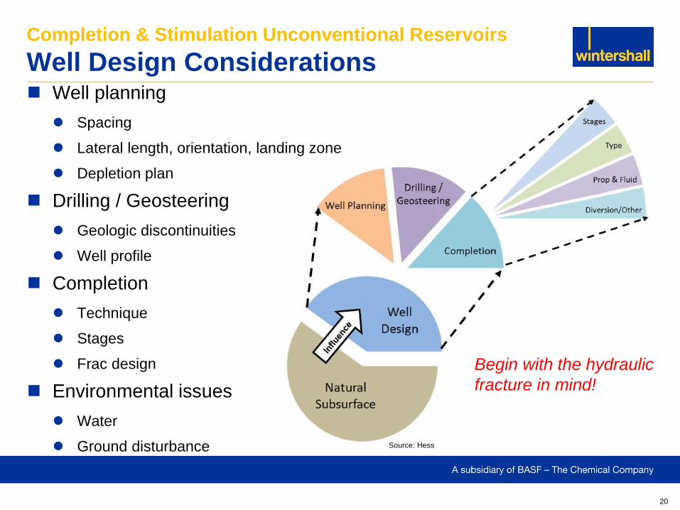
Well planning
Spacing
Lateral length, orientation, landing zone
Depletion plan
Drilling / Geosteering
Geologic discontinuities
Well profile
Completion
Technique
Stages
Frac design
Environmental issues
Water
Ground disturbance
Completion & Stimulation Unconventional Reservoirs
Well Design Considerations
Source: Hess
Begin with the hydraulic
fracture in mind!
21
Completion & Stimulation Unconventional Reservoirs
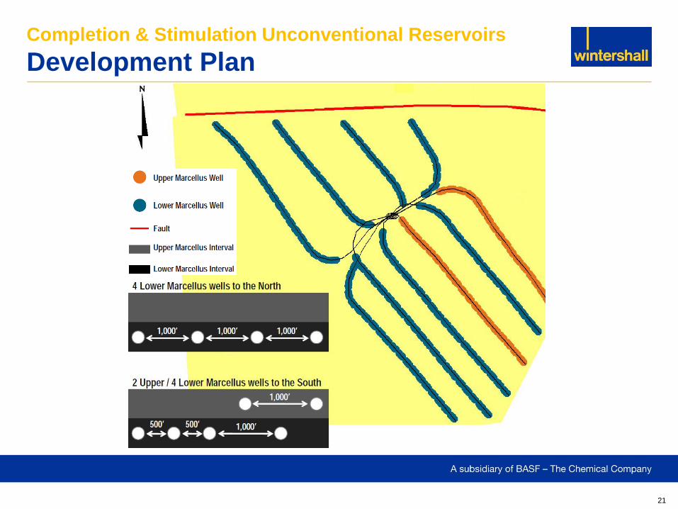
Development Plan
22
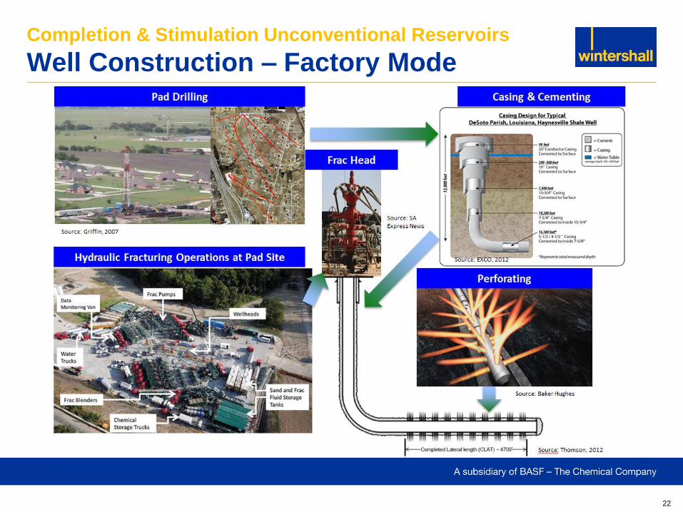
Completion & Stimulation Unconventional Reservoirs
Well Construction – Factory Mode
23
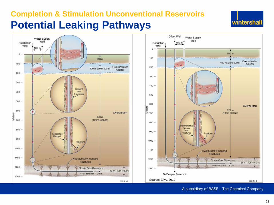
Completion & Stimulation Unconventional Reservoirs
Potential Leaking Pathways
Source: EPA, 2012
24
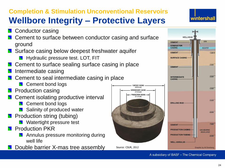
Completion & Stimulation Unconventional Reservoirs
Wellbore Integrity – Protective Layers Conductor casing
Cement to surface between conductor casing and surface
ground
Surface casing below deepest freshwater aquifer
Hydraulic pressure test. LOT, FIT
Cement to surface sealing surface casing in place
Intermediate casing
Cement to seal intermediate casing in place Cement bond logs
Production casing
Cement isolating productive interval Cement bond logs
Salinity of produced water
Production string (tubing) Watertight pressure test
Production PKR Annulus pressure monitoring during
well life
Double barrier X-mas tree assembly Source: CSUR, 2012
25
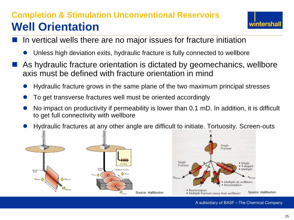
In vertical wells there are no major issues for fracture initiation
Unless high deviation exits, hydraulic fracture is fully connected to wellbore
As hydraulic fracture orientation is dictated by geomechanics, wellbore axis must be defined with fracture orientation in mind
Hydraulic fracture grows in the same plane of the two maximum principal stresses
To get transverse fractures well must be oriented accordingly
No impact on productivity if permeability is lower than 0.1 mD. In addition, it is difficult to get full connectivity with wellbore
Hydraulic fractures at any other angle are difficult to initiate. Tortuosity. Screen-outs
Completion & Stimulation Unconventional Reservoirs
Well Orientation
Source: Halliburton Source: Halliburton
26
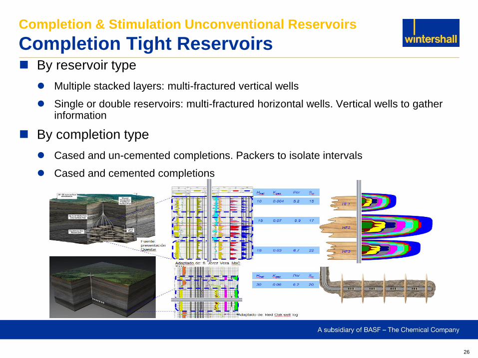
By reservoir type
Multiple stacked layers: multi-fractured vertical wells
Single or double reservoirs: multi-fractured horizontal wells. Vertical wells to gather information
By completion type
Cased and un-cemented completions. Packers to isolate intervals
Cased and cemented completions
Completion & Stimulation Unconventional Reservoirs
Completion Tight Reservoirs
27
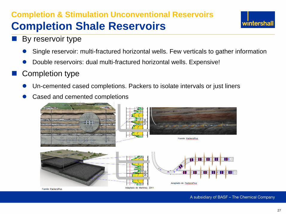
By reservoir type
Single reservoir: multi-fractured horizontal wells. Few verticals to gather information
Double reservoirs: dual multi-fractured horizontal wells. Expensive!
Completion type
Un-cemented cased completions. Packers to isolate intervals or just liners
Cased and cemented completions
Completion & Stimulation Unconventional Reservoirs
Completion Shale Reservoirs
28
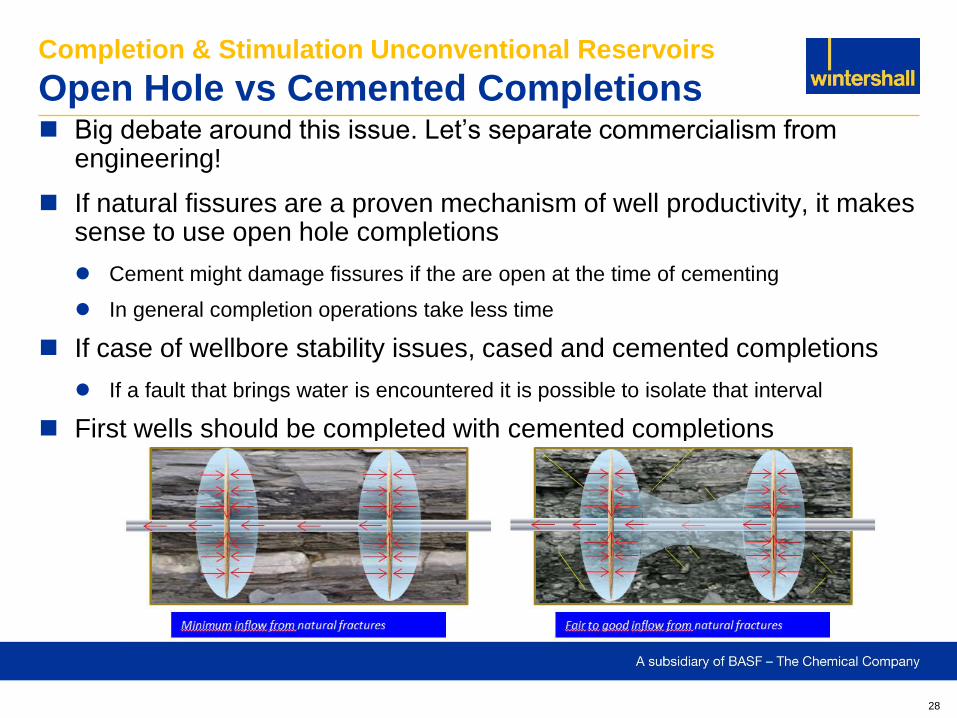
Big debate around this issue. Let’s separate commercialism from engineering!
If natural fissures are a proven mechanism of well productivity, it makes sense to use open hole completions
Cement might damage fissures if the are open at the time of cementing
In general completion operations take less time
If case of wellbore stability issues, cased and cemented completions
If a fault that brings water is encountered it is possible to isolate that interval
First wells should be completed with cemented completions
Completion & Stimulation Unconventional Reservoirs
Open Hole vs Cemented Completions
29
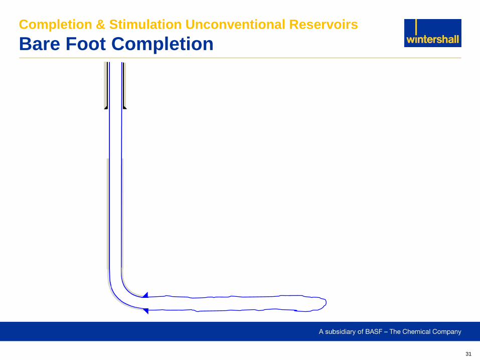
Open hole completions
Bare foot
– Lowest cost
– Simple
– No cement = no damage but no isolation
– No diversion
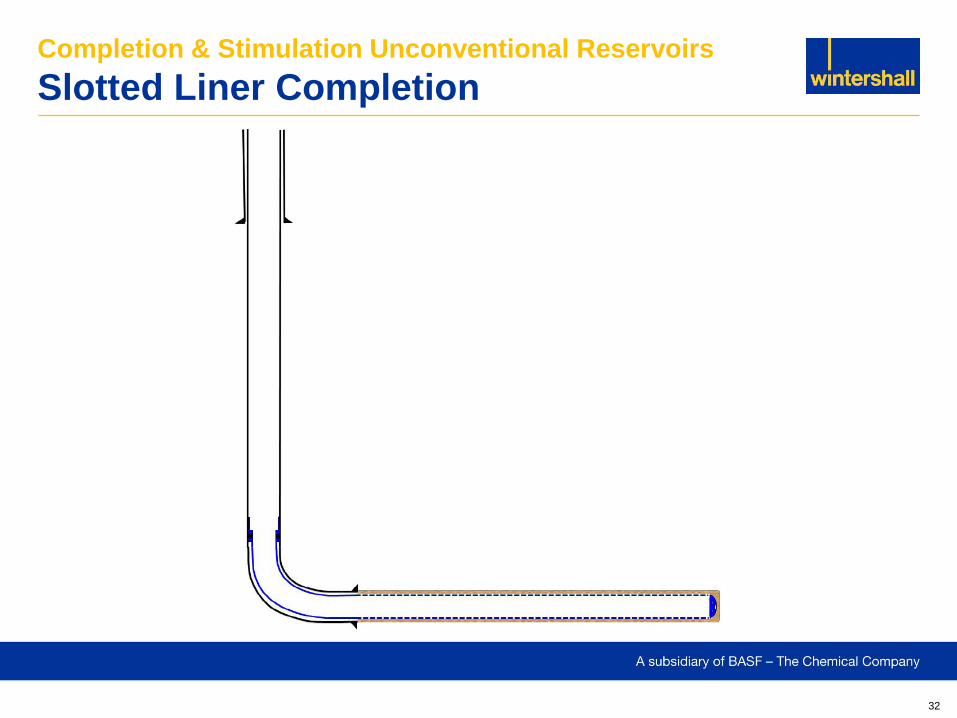
Slotted liner
– Low cost
– Simple
– No cement as previous method
– Poor diversion
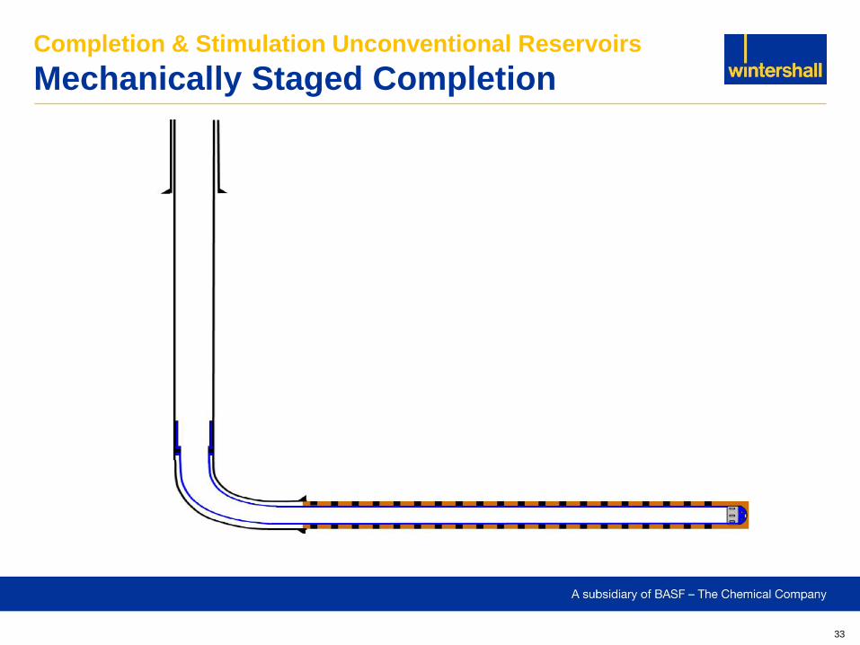
Mechanically staged process
– Affordable cost
– No cement as previous methods
– Diversion is ensured
– Operationally simple but…
Completion & Stimulation Unconventional Reservoirs
History of Completion Techniques
30
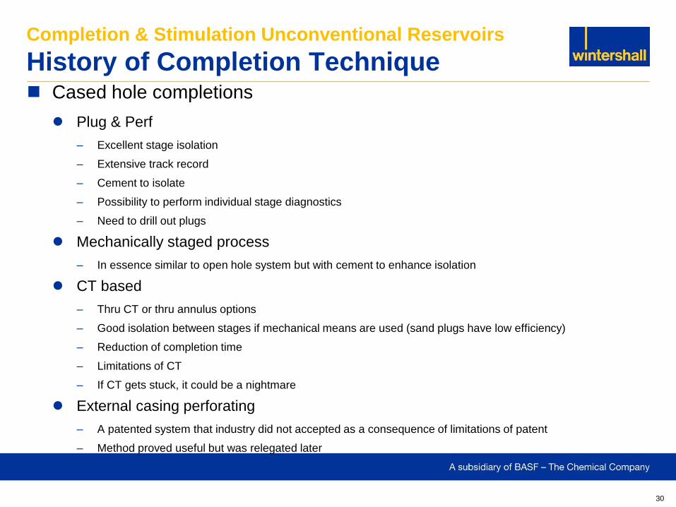
Cased hole completions
Plug & Perf
– Excellent stage isolation
– Extensive track record
– Cement to isolate
– Possibility to perform individual stage diagnostics
– Need to drill out plugs
Mechanically staged process
– In essence similar to open hole system but with cement to enhance isolation
CT based
– Thru CT or thru annulus options
– Good isolation between stages if mechanical means are used (sand plugs have low efficiency)
– Reduction of completion time
– Limitations of CT
– If CT gets stuck, it could be a nightmare
External casing perforating
– A patented system that industry did not accepted as a consequence of limitations of patent
– Method proved useful but was relegated later
Completion & Stimulation Unconventional Reservoirs
History of Completion Technique
31
Completion & Stimulation Unconventional Reservoirs
Bare Foot Completion
32
Completion & Stimulation Unconventional Reservoirs
Slotted Liner Completion
33
Completion & Stimulation Unconventional Reservoirs
Mechanically Staged Completion
34
Cased and cemented
Cased and un-cemented
Completion & Stimulation Unconventional Reservoirs
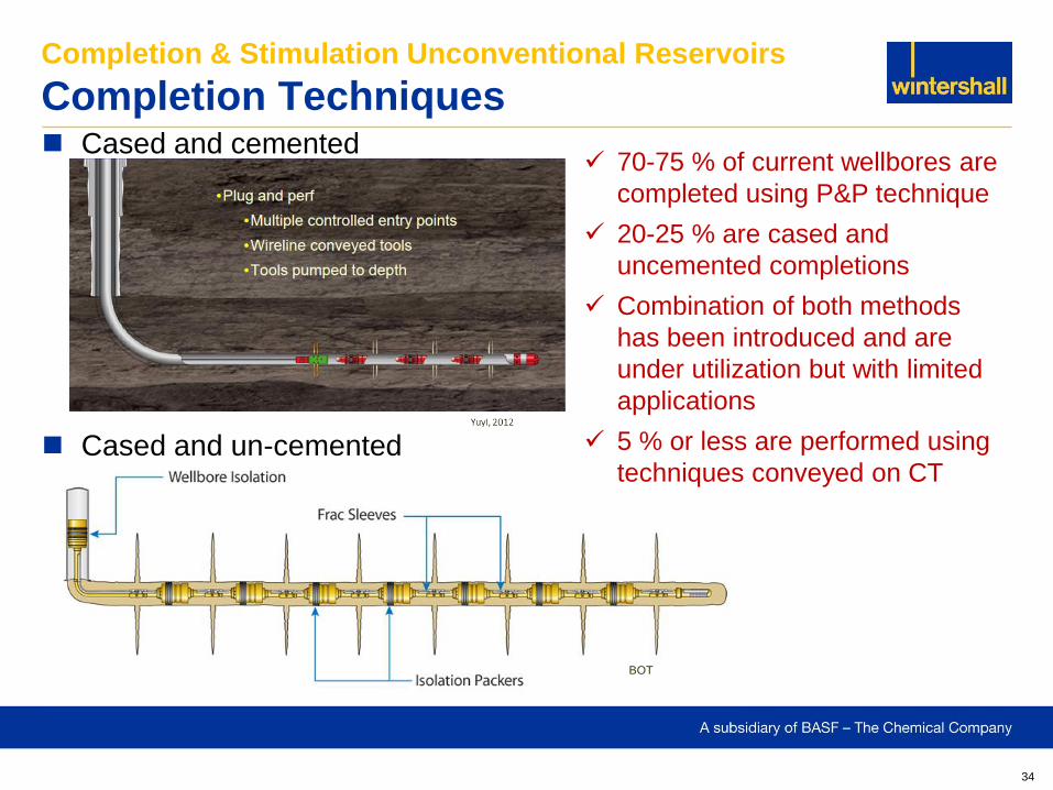
Completion Techniques
BOT
70-75 % of current wellbores are
completed using P&P technique
20-25 % are cased and
uncemented completions
Combination of both methods
has been introduced and are
under utilization but with limited
applications
5 % or less are performed using
techniques conveyed on CT
35
First stage
TCP perforating conveyed on CT
Abrasive jet perforating conveyed on CT or jointed pipe
Casing gun perforating conveyed on wireline tractor
Casing toe gun
Hydraulic valve
Toe valve
Wet shoe
Rupture disk
Subsequent stages
Wireline conveyed casing gun perforating
TCP perforating conveyed on CT
Abrasive jet perforating conveyed on CT or jointed pipe
Casing gun perforating conveyed on wireline tractor
Completion & Stimulation Unconventional Reservoirs
Cased and Cemented
36
First stage
Hydraulic valve
Toe valve
Rupture disk
TCP perforating conveyed on CT or jointed pipe (contingency)
Abrasive jet perforating conveyed on CT (contingency)
Casing gun perforating conveyed on wireline tractor (contingency)
Subsequent stages
Single or multiple array of farc sleeves / ports
TCP perforating conveyed on CT (back up plan after DO ball seats)
Abrasive jet perforating (back up plan after DO ball seats)
TCP perforating conveyed on wireline tractor (back up plan after DO ball seats)
Wireline conveyed casing gun perforating (back up plan after DO ball seats)
Completion & Stimulation Unconventional Reservoirs
Cased and Un-cemented
37
Completion & Stimulation Unconventional Reservoirs
Pro’s and Con’s – Quick Review Fix devices run as part of completion string (e.g. frac ports)
Need to have really good understanding or reservoir quality to define landing depth of every frac port in front of sweet spots
Short time for analyses as completion is run as part of the production string. It requires dedicated, efficient and well integrated teams
Frac behavior must not be an issue, likelihood of screening out is remote. Development phase
Not recommended for exploration, appraisal stage
Excellent balance between cost and completion cycle time
It requires very good communication between operational crews from different service providers on location to avoid serious mistakes
When open hole completion is used and natural fissures provide some production they must be considered seriously
Isolation between stages can be questionable under certain conditions
Wellbore stability is a key issue when deciding to use this technology
38
Completion & Stimulation Unconventional Reservoirs
Pro’s and Con’s – Quick Review Pin point stimulation
Fracs are directly targeted where the teams want to
Time for reservoir related analyses is not an issue
From completion cycle time perspective is much more less effective than frac ports systems. (average: 3 to 7 stages in one day)
Highly recommended for exploratory and appraisal wells
If sanding out happens it is easy to clean out the excess of proppant and continue with the program
Versatility to change decisions as we always have the control on where to put the perfs
These are cased and cemented completions so we need to rely on cement isolation (an issue in horizontal wells)
If any production is coming from natural fissures we are not capturing it
Easy for operational crews on location to understand the methodology
39
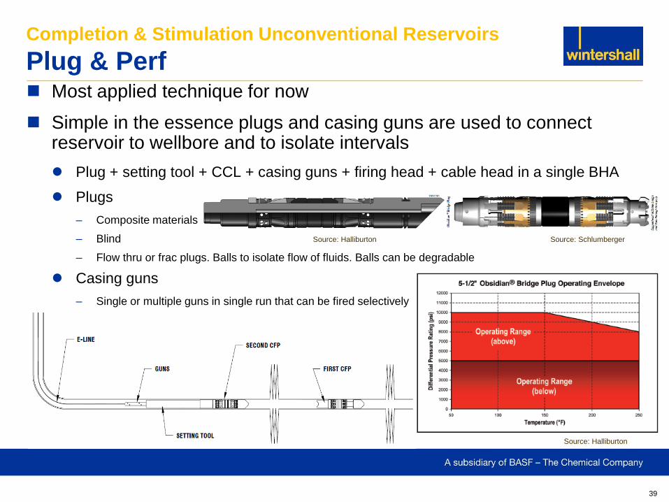
Most applied technique for now
Simple in the essence plugs and casing guns are used to connect reservoir to wellbore and to isolate intervals
Plug + setting tool + CCL + casing guns + firing head + cable head in a single BHA
Plugs
– Composite materials
– Blind
– Flow thru or frac plugs. Balls to isolate flow of fluids. Balls can be degradable
Casing guns
– Single or multiple guns in single run that can be fired selectively
Completion & Stimulation Unconventional Reservoirs
Plug & Perf
Source: Halliburton
Source: Schlumberger Source: Halliburton
40
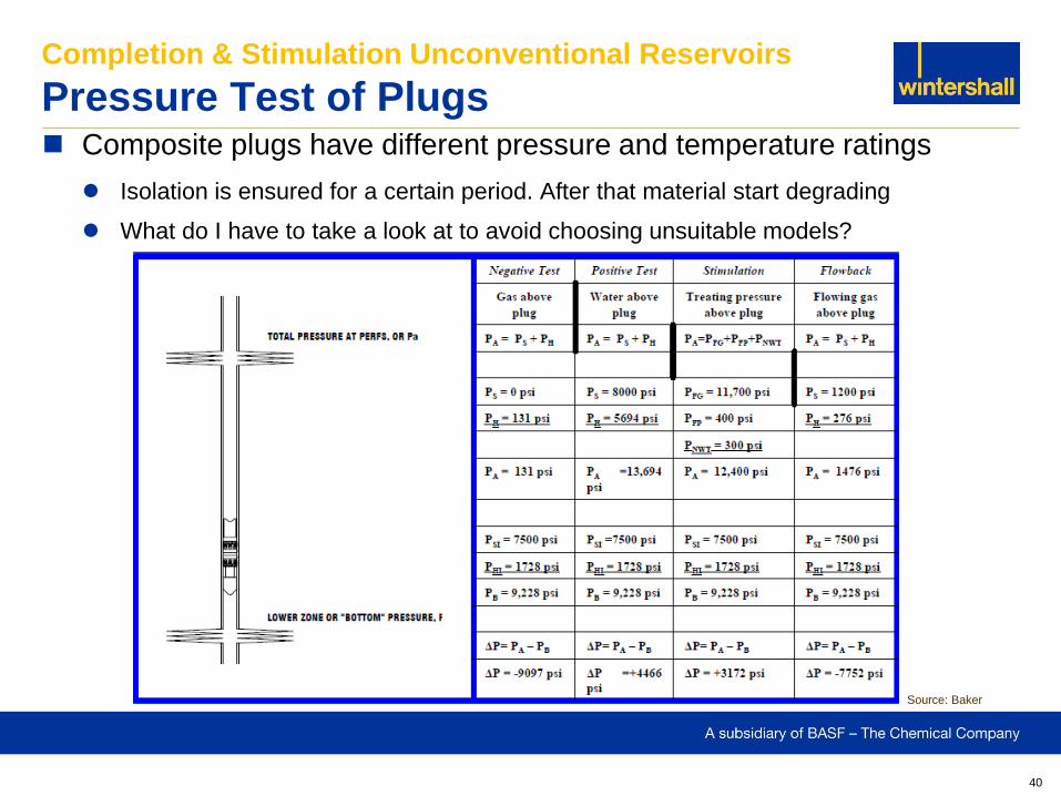
Composite plugs have different pressure and temperature ratings
Isolation is ensured for a certain period. After that material start degrading
What do I have to take a look at to avoid choosing unsuitable models?
Completion & Stimulation Unconventional Reservoirs
Pressure Test of Plugs
Source: Baker
41
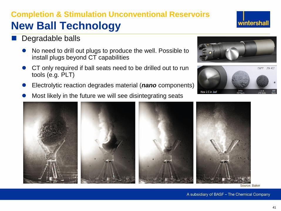
Degradable balls
No need to drill out plugs to produce the well. Possible to install plugs beyond CT capabilities
CT only required if ball seats need to be drilled out to run tools (e.g. PLT)
Electrolytic reaction degrades material (nano components)
Most likely in the future we will see disintegrating seats
Completion & Stimulation Unconventional Reservoirs
New Ball Technology
Source: Baker
42
Plug & Perf technique implies pumping down casing guns and plugs
To increase efficiency both are pumped together in a single run
A clean wellbore is critical
Sand or debris can cause downhole tools to get stuck
Previous frac stage must be flushed properly
Flush surface equipment (mainly well control devices) to ensure no proppant remains inside that prevent them to work properly
Weight control is crucial during entire operation
Weight check in vertical section. Tension in the horizontal section should be close to this value. Ensure to check weight at the same rate you pump in the horizontal
Pump down rate depends on casing size
At least 10 bpm are required to push the plugs but 15 to 20 bpm are typical
Pump at 2 bpm while perforating to ensure cable is in tension and to prevent stuck
Communication is paramount between wireline and pump trucks
Completion & Stimulation Unconventional Reservoirs
Pump Down Operations
43
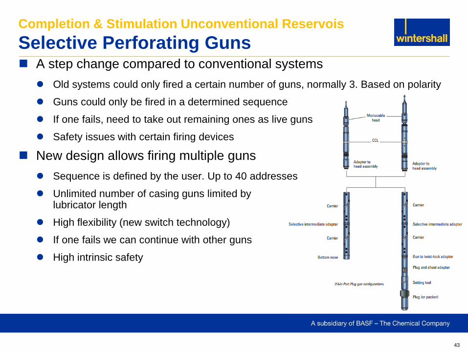
A step change compared to conventional systems
Old systems could only fired a certain number of guns, normally 3. Based on polarity
Guns could only be fired in a determined sequence
If one fails, need to take out remaining ones as live guns
Safety issues with certain firing devices
New design allows firing multiple guns
Sequence is defined by the user. Up to 40 addresses
Unlimited number of casing guns limited by lubricator length
High flexibility (new switch technology)
If one fails we can continue with other guns
High intrinsic safety
Completion & Stimulation Unconventional Reservois
Selective Perforating Guns
44
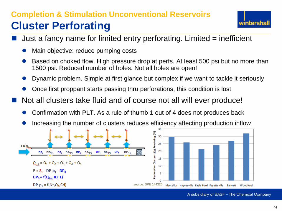
Just a fancy name for limited entry perforating. Limited = inefficient
Main objective: reduce pumping costs
Based on choked flow. High pressure drop at perfs. At least 500 psi but no more than 1500 psi. Reduced number of holes. Not all holes are open!
Dynamic problem. Simple at first glance but complex if we want to tackle it seriously
Once first proppant starts passing thru perforations, this condition is lost
Not all clusters take fluid and of course not all will ever produce!
Confirmation with PLT. As a rule of thumb 1 out of 4 does not produces back
Increasing the number of clusters reduces efficiency affecting production inflow
Completion & Stimulation Unconventional Reservoirs
Cluster Perforating
source: SPE 144326
45
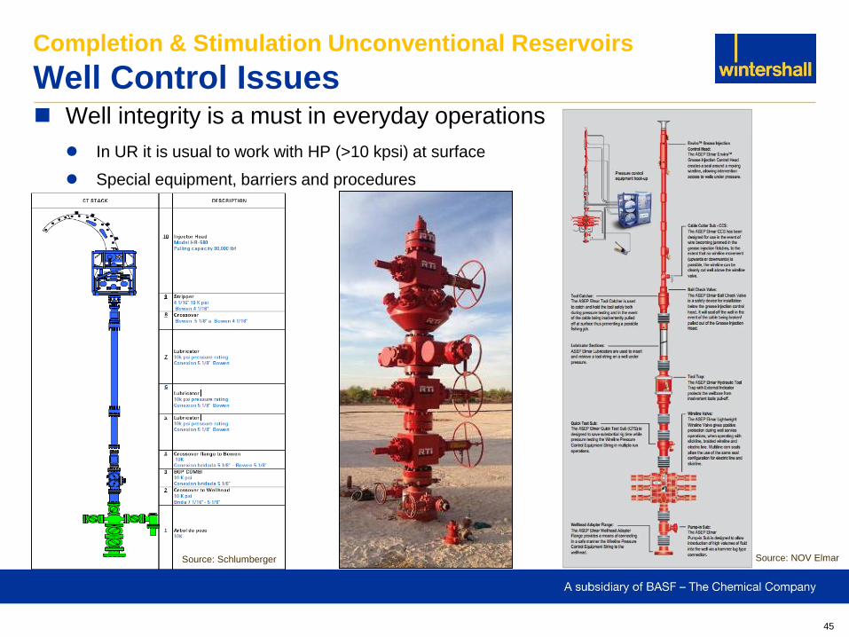
Well integrity is a must in everyday operations
In UR it is usual to work with HP (>10 kpsi) at surface
Special equipment, barriers and procedures
Completion & Stimulation Unconventional Reservoirs
Well Control Issues
Source: NOV Elmar Source: Schlumberger
46
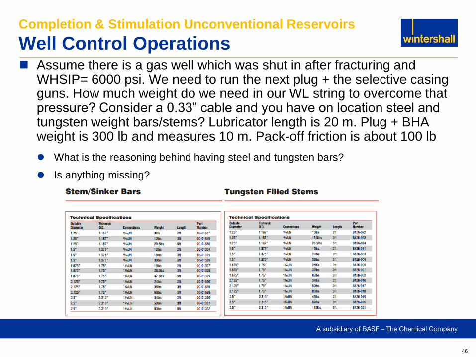
Assume there is a gas well which was shut in after fracturing and WHSIP= 6000 psi. We need to run the next plug + the selective casing guns. How much weight do we need in our WL string to overcome that pressure? Consider a 0.33” cable and you have on location steel and tungsten weight bars/stems? Lubricator length is 20 m. Plug + BHA weight is 300 lb and measures 10 m. Pack-off friction is about 100 lb
What is the reasoning behind having steel and tungsten bars?
Is anything missing?
Completion & Stimulation Unconventional Reservoirs
Well Control Operations
47
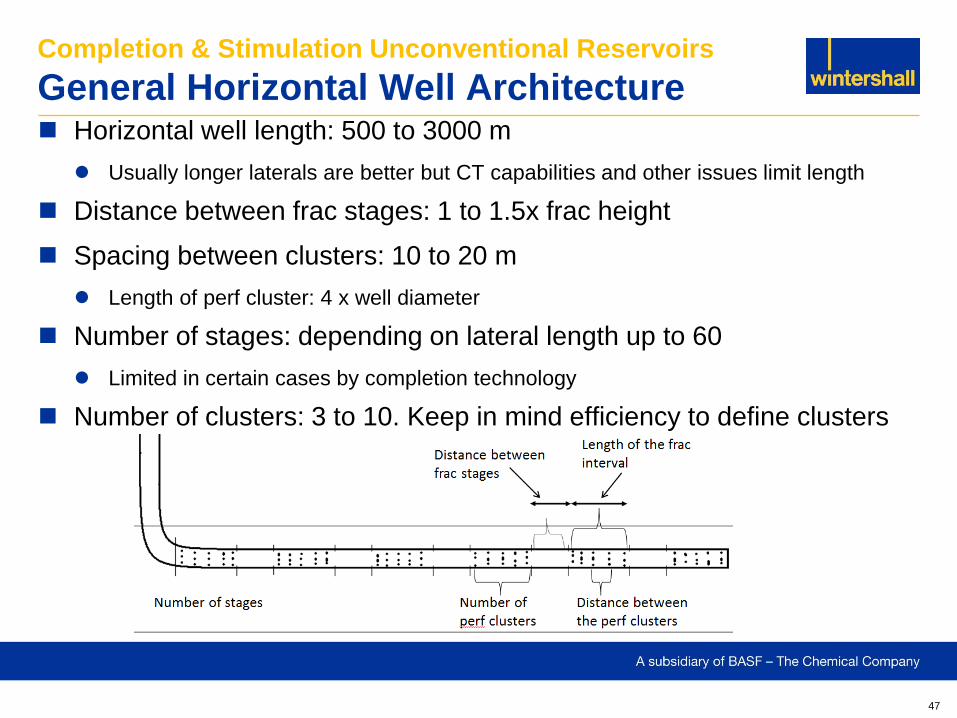
Horizontal well length: 500 to 3000 m
Usually longer laterals are better but CT capabilities and other issues limit length
Distance between frac stages: 1 to 1.5x frac height
Spacing between clusters: 10 to 20 m
Length of perf cluster: 4 x well diameter
Number of stages: depending on lateral length up to 60
Limited in certain cases by completion technology
Number of clusters: 3 to 10. Keep in mind efficiency to define clusters
Completion & Stimulation Unconventional Reservoirs
General Horizontal Well Architecture
48
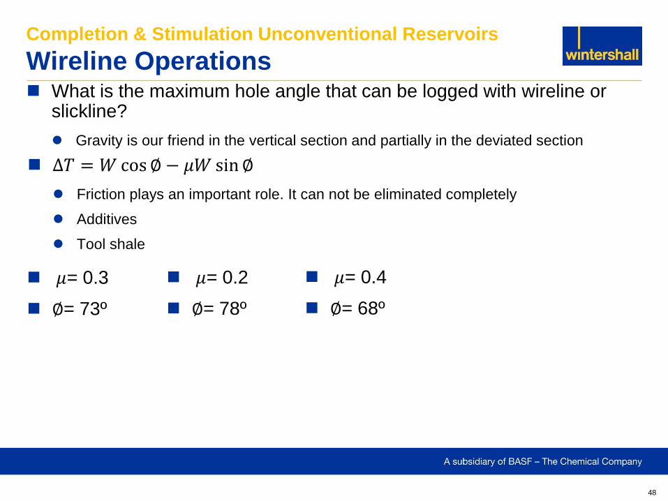
What is the maximum hole angle that can be logged with wireline or slickline?
Gravity is our friend in the vertical section and partially in the deviated section
Completion & Stimulation Unconventional Reservoirs
Wireline Operations
∆𝑇 = 𝑊 cos ∅ − 𝜇𝑊 sin ∅
Friction plays an important role. It can not be eliminated completely
Additives
Tool shale
𝜇= 0.3
∅= 73º
𝜇= 0.2
∅= 78º
𝜇= 0.4
∅= 68º
49
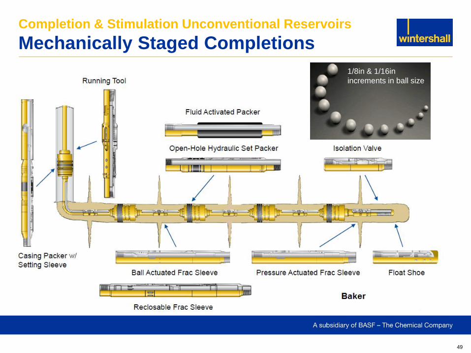
Completion & Stimulation Unconventional Reservoirs
Mechanically Staged Completions
1/8in & 1/16in
increments in ball size
50
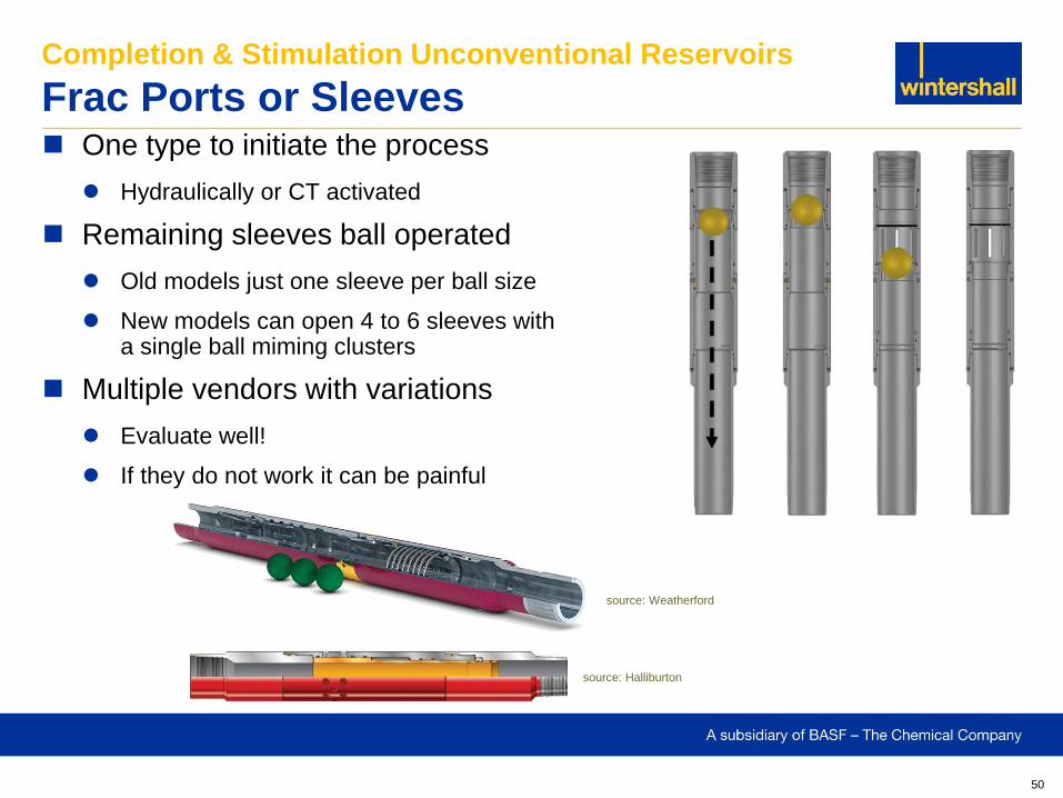
One type to initiate the process
Hydraulically or CT activated
Remaining sleeves ball operated
Old models just one sleeve per ball size
New models can open 4 to 6 sleeves with a single ball miming clusters
Multiple vendors with variations
Evaluate well!
If they do not work it can be painful
Completion & Stimulation Unconventional Reservoirs
Frac Ports or Sleeves
source: Halliburton
source: Weatherford
51
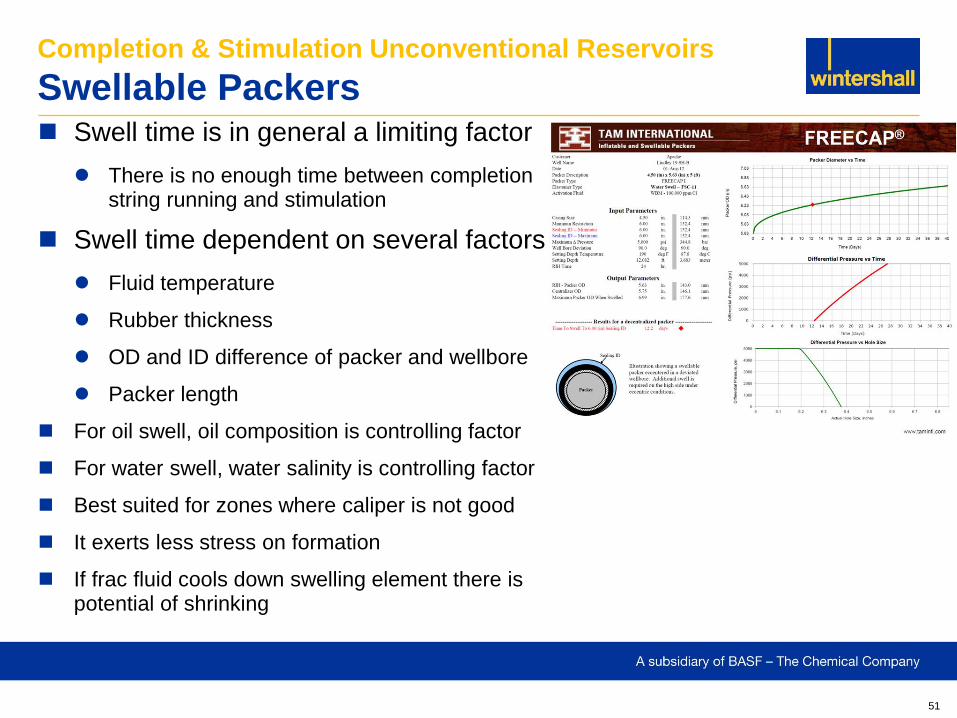
Swell time is in general a limiting factor
There is no enough time between completion string running and stimulation
Swell time dependent on several factors
Fluid temperature
Rubber thickness
OD and ID difference of packer and wellbore
Packer length
For oil swell, oil composition is controlling factor
For water swell, water salinity is controlling factor
Best suited for zones where caliper is not good
It exerts less stress on formation
If frac fluid cools down swelling element there is potential of shrinking
Completion & Stimulation Unconventional Reservoirs
Swellable Packers
52
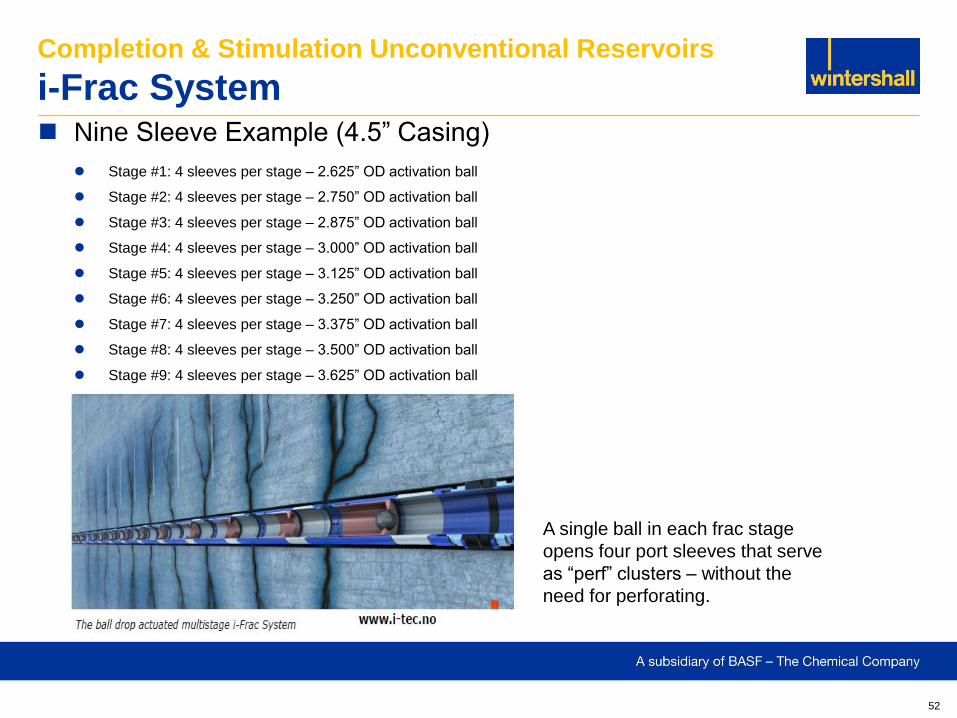
Nine Sleeve Example (4.5” Casing)
Stage #1: 4 sleeves per stage – 2.625” OD activation ball
Stage #2: 4 sleeves per stage – 2.750” OD activation ball
Stage #3: 4 sleeves per stage – 2.875” OD activation ball
Stage #4: 4 sleeves per stage – 3.000” OD activation ball
Stage #5: 4 sleeves per stage – 3.125” OD activation ball
Stage #6: 4 sleeves per stage – 3.250” OD activation ball
Stage #7: 4 sleeves per stage – 3.375” OD activation ball
Stage #8: 4 sleeves per stage – 3.500” OD activation ball
Stage #9: 4 sleeves per stage – 3.625” OD activation ball
Completion & Stimulation Unconventional Reservoirs
i-Frac System
A single ball in each frac stage
opens four port sleeves that serve
as “perf” clusters – without the
need for perforating.
53
Completion & Stimulation Unconventional Reservoirs
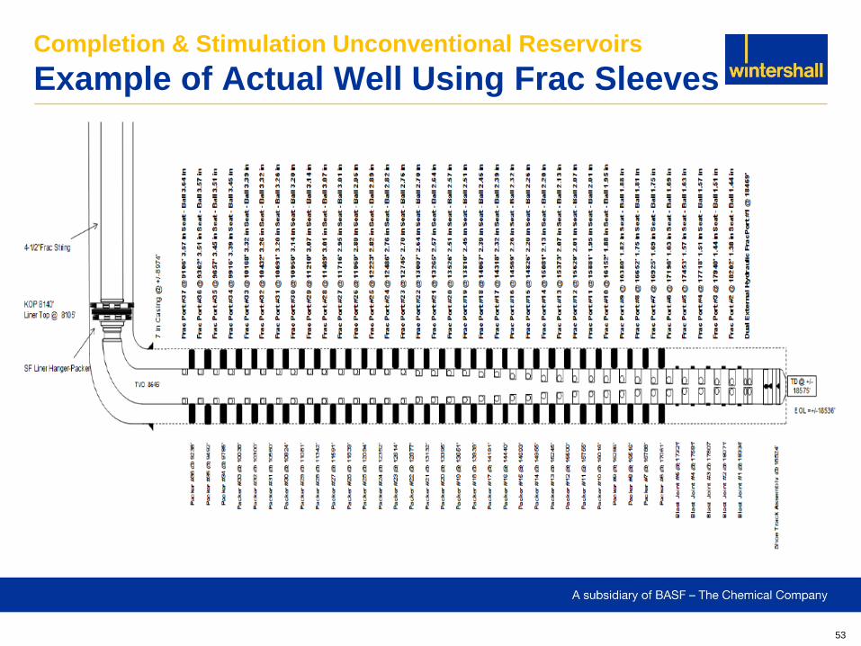
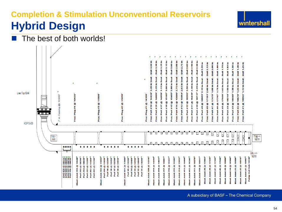
Example of Actual Well Using Frac Sleeves
54
The best of both worlds!
Completion & Stimulation Unconventional Reservoirs
Hybrid Design
55
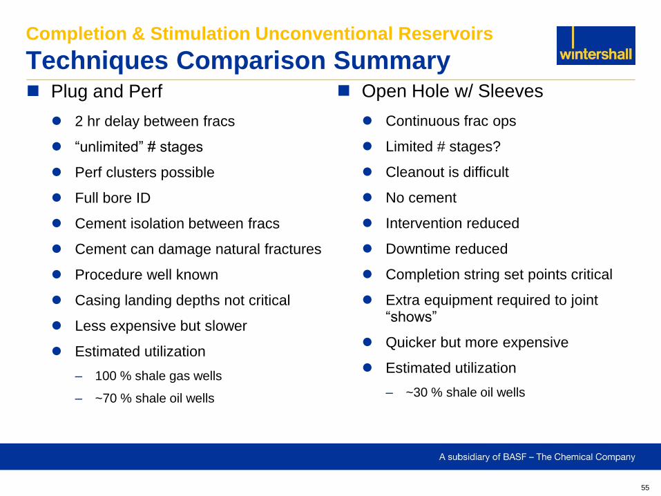
Plug and Perf
2 hr delay between fracs
“unlimited” # stages
Perf clusters possible
Full bore ID
Cement isolation between fracs
Cement can damage natural fractures
Procedure well known
Casing landing depths not critical
Less expensive but slower
Estimated utilization
– 100 % shale gas wells
– ~70 % shale oil wells
Completion & Stimulation Unconventional Reservoirs
Techniques Comparison Summary Open Hole w/ Sleeves
Continuous frac ops
Limited # stages?
Cleanout is difficult
No cement
Intervention reduced
Downtime reduced
Completion string set points critical
Extra equipment required to joint “shows”
Quicker but more expensive
Estimated utilization
– ~30 % shale oil wells
56
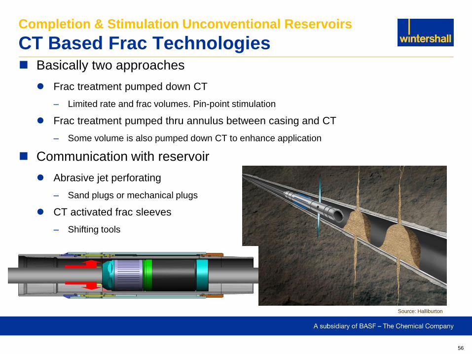
Basically two approaches
Frac treatment pumped down CT
– Limited rate and frac volumes. Pin-point stimulation
Frac treatment pumped thru annulus between casing and CT
– Some volume is also pumped down CT to enhance application
Communication with reservoir
Abrasive jet perforating
– Sand plugs or mechanical plugs
CT activated frac sleeves
– Shifting tools
Completion & Stimulation Unconventional Reservoirs
CT Based Frac Technologies
Source: Halliburton
57
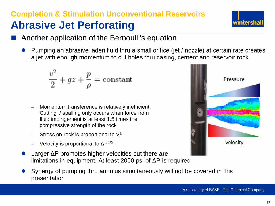
Another application of the Bernoulli's equation
Pumping an abrasive laden fluid thru a small orifice (jet / nozzle) at certain rate creates a jet with enough momentum to cut holes thru casing, cement and reservoir rock
– Momentum transference is relatively inefficient. Cutting / spalling only occurs when force from fluid impingement is at least 1.5 times the compressive strength of the rock
– Stress on rock is proportional to V2
– Velocity is proportional to ΔP1/2
Larger ΔP promotes higher velocities but there are limitations in equipment. At least 2000 psi of ΔP is required
Synergy of pumping thru annulus simultaneously will not be covered in this presentation
Completion & Stimulation Unconventional Reservoirs
Abrasive Jet Perforating
58
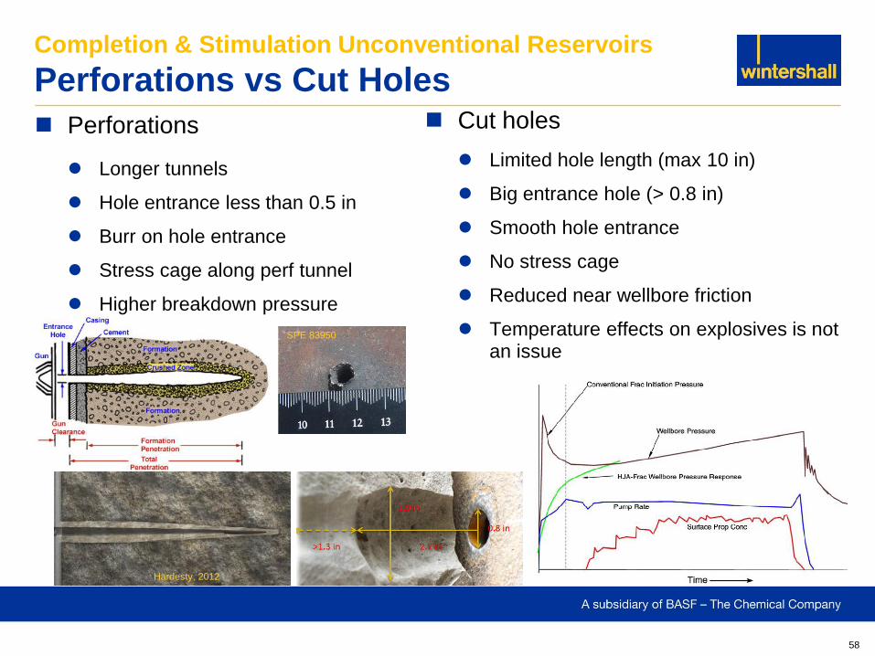
Perforations
Longer tunnels
Hole entrance less than 0.5 in
Burr on hole entrance
Stress cage along perf tunnel
Higher breakdown pressure
Completion & Stimulation Unconventional Reservoirs
Perforations vs Cut Holes Cut holes
Limited hole length (max 10 in)
Big entrance hole (> 0.8 in)
Smooth hole entrance
No stress cage
Reduced near wellbore friction
Temperature effects on explosives is not an issue
Hardesty, 2012
SPE 83950
59
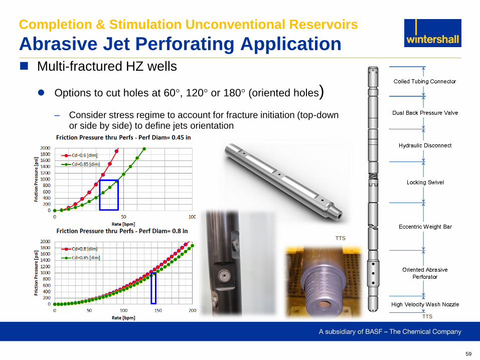
Multi-fractured HZ wells
Options to cut holes at 60°, 120° or 180° (oriented holes)
– Consider stress regime to account for fracture initiation (top-down or side by side) to define jets orientation
Completion & Stimulation Unconventional Reservoirs
Abrasive Jet Perforating Application
TTS
TTS
60
Completion & Stimulation Unconventional Reservoirs
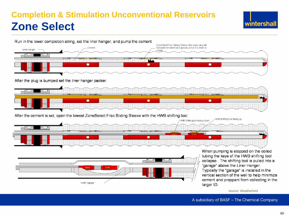
Zone Select
source: Weatherford
61
Completion & Stimulation Unconventional Reservoirs
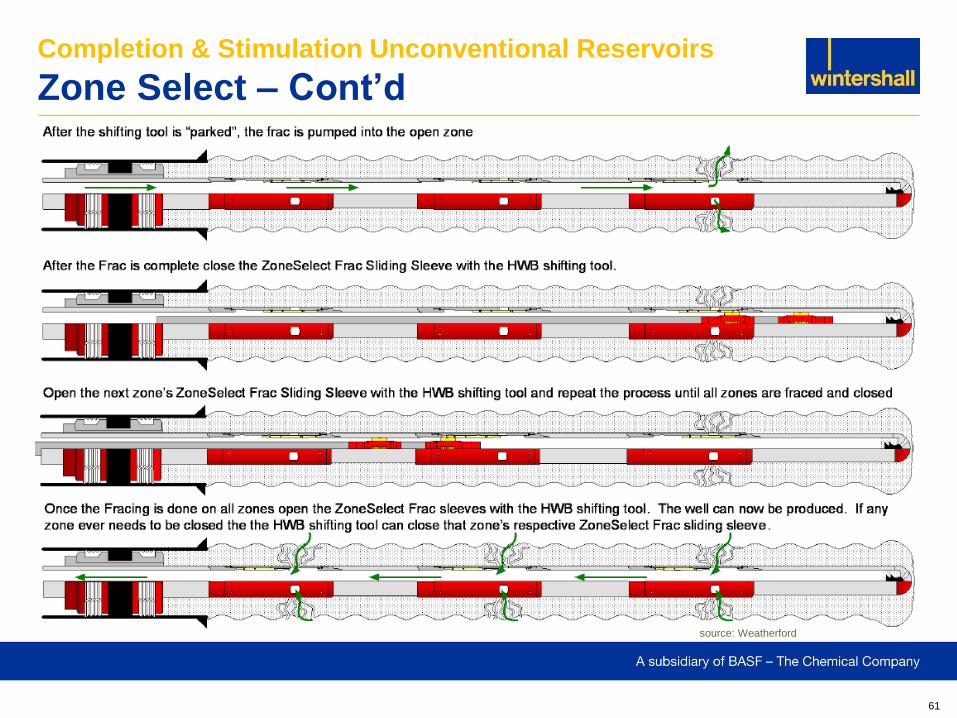
Zone Select – Cont’d
source: Weatherford
62
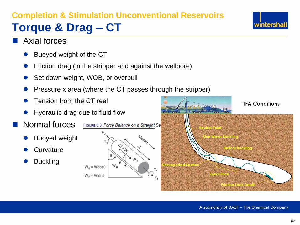
Axial forces
Buoyed weight of the CT
Friction drag (in the stripper and against the wellbore)
Set down weight, WOB, or overpull
Pressure x area (where the CT passes through the stripper)
Tension from the CT reel
Hydraulic drag due to fluid flow
Normal forces
Buoyed weight
Curvature
Buckling
Completion & Stimulation Unconventional Reservoirs
Torque & Drag – CT
63
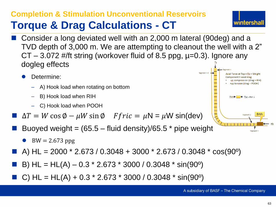
Consider a long deviated well with an 2,000 m lateral (90deg) and a TVD depth of 3,000 m. We are attempting to cleanout the well with a 2” CT – 3.072 #/ft string (workover fluid of 8.5 ppg, µ=0.3). Ignore any dogleg effects
Determine:
– A) Hook load when rotating on bottom
– B) Hook load when RIH
– C) Hook load when POOH
Completion & Stimulation Unconventional Reservoirs
Torque & Drag Calculations - CT
∆𝑇 = 𝑊 cos ∅ − 𝜇𝑊 sin ∅ 𝐹𝑓𝑟𝑖𝑐 = 𝜇N = 𝜇W sin(dev)
Buoyed weight = (65.5 – fluid density)/65.5 * pipe weight
BW = 2.673 ppg
A) HL = 2000 * 2.673 / 0.3048 + 3000 * 2.673 / 0.3048 * cos(90º)
B) HL = HL(A) – 0.3 * 2.673 * 3000 / 0.3048 * sin(90º)
C) HL = HL(A) + 0.3 * 2.673 * 3000 / 0.3048 * sin(90º)
64
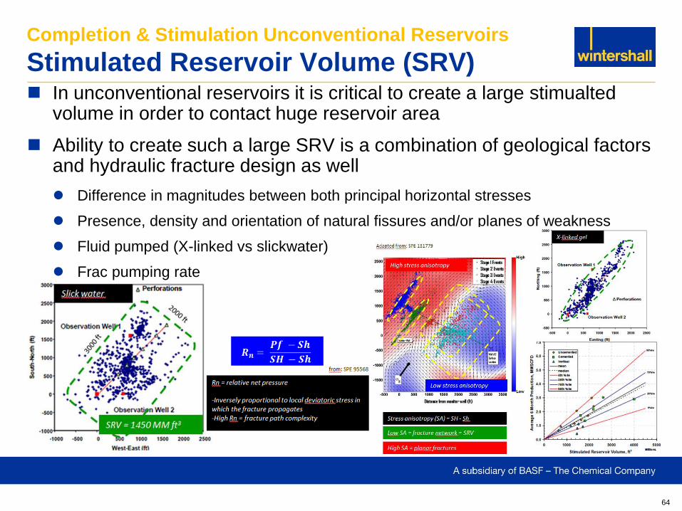
In unconventional reservoirs it is critical to create a large stimualted volume in order to contact huge reservoir area
Ability to create such a large SRV is a combination of geological factors and hydraulic fracture design as well
Difference in magnitudes between both principal horizontal stresses
Presence, density and orientation of natural fissures and/or planes of weakness
Fluid pumped (X-linked vs slickwater)
Frac pumping rate
Completion & Stimulation Unconventional Reservoirs
Stimulated Reservoir Volume (SRV)
65
Completion & Stimulation Unconventional Reservoirs
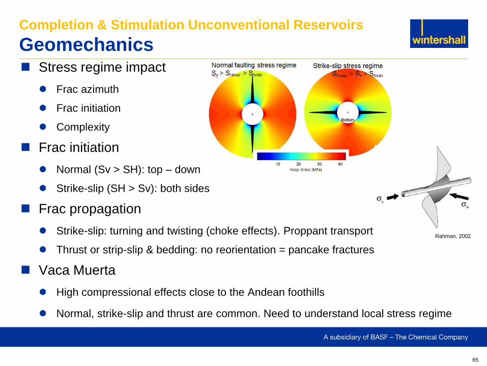
Geomechanics Stress regime impact
Frac azimuth
Frac initiation
Complexity
Frac initiation
Normal (Sv > SH): top – down
Strike-slip (SH > Sv): both sides
Frac propagation
Strike-slip: turning and twisting (choke effects). Proppant transport
Thrust or strip-slip & bedding: no reorientation = pancake fractures
Vaca Muerta
High compressional effects close to the Andean foothills
Normal, strike-slip and thrust are common. Need to understand local stress regime
Rahman, 2002
66
Completion & Stimulation Unconventional Reservoirs
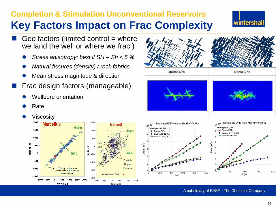
Key Factors Impact on Frac Complexity Geo factors (limited control = where
we land the well or where we frac )
Stress anisotropy: best if SH – Sh < 5 %
Natural fissures (density) / rock fabrics
Mean stress magnitude & direction
Frac design factors (manageable)
Wellbore orientation
Rate
Viscosity
67
Completion & Stimulation Unconventional Reservoirs
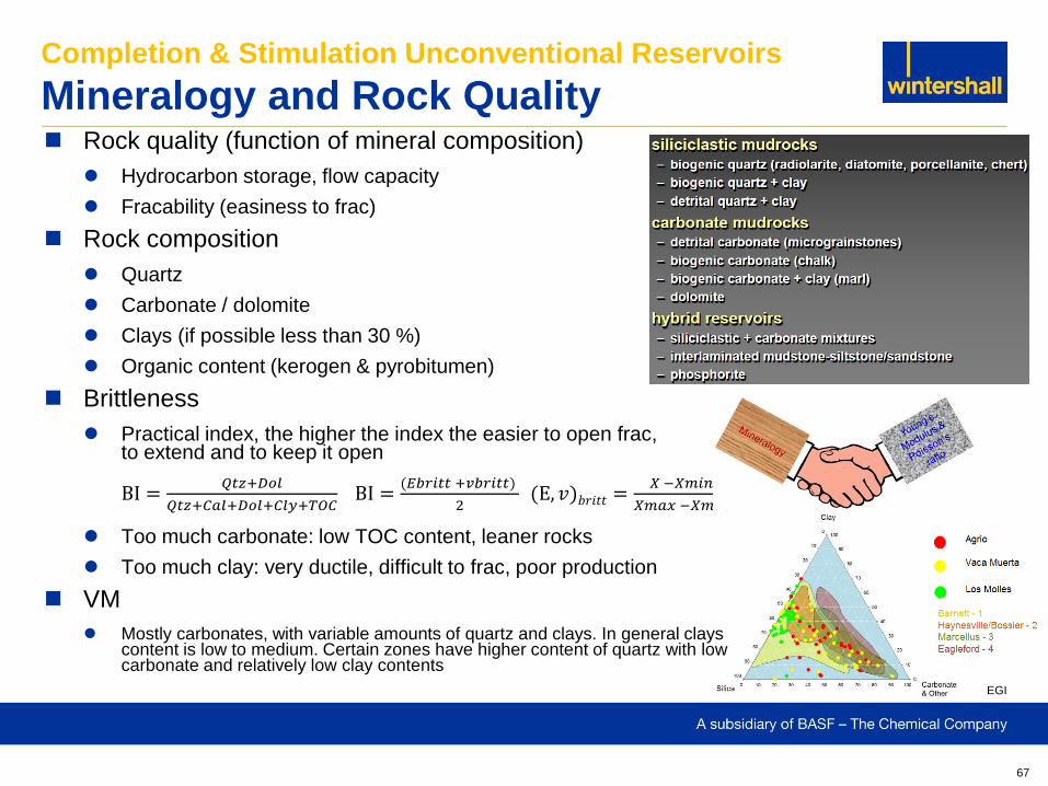
Mineralogy and Rock Quality Rock quality (function of mineral composition)
Hydrocarbon storage, flow capacity
Fracability (easiness to frac)
Rock composition
Quartz
Carbonate / dolomite
Clays (if possible less than 30 %)
Organic content (kerogen & pyrobitumen)
Brittleness
Practical index, the higher the index the easier to open frac, to extend and to keep it open BI =
𝑄𝑡𝑧+𝐷𝑜𝑙
𝑄𝑡𝑧+𝐶𝑎𝑙+𝐷𝑜𝑙+𝐶𝑙𝑦+𝑇𝑂𝐶 BI =
(𝐸𝑏𝑟𝑖𝑡𝑡 +𝑣𝑏𝑟𝑖𝑡𝑡)
2 (E, 𝑣)𝑏𝑟𝑖𝑡𝑡 =
𝑋 −𝑋𝑚𝑖𝑛
𝑋𝑚𝑎𝑥 −𝑋𝑚𝑖𝑛
Too much carbonate: low TOC content, leaner rocks
Too much clay: very ductile, difficult to frac, poor production
VM
Mostly carbonates, with variable amounts of quartz and clays. In general clays content is low to medium. Certain zones have higher content of quartz with low carbonate and relatively low clay contents
EGI
68
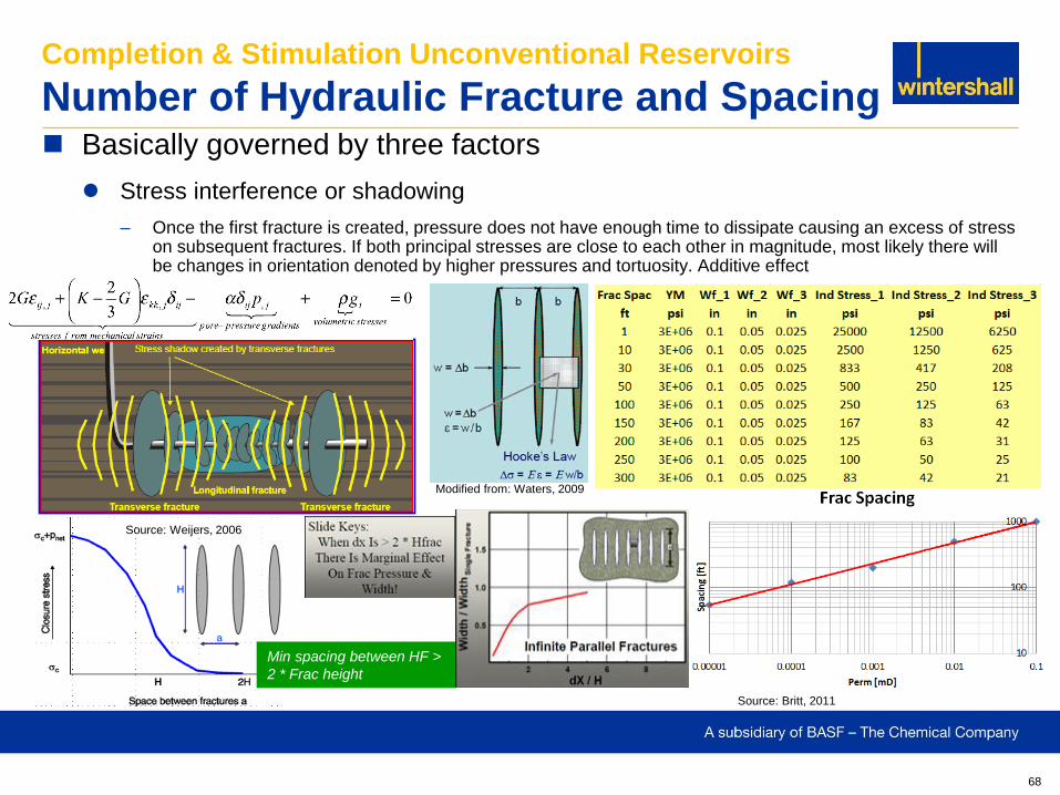
Basically governed by three factors
Stress interference or shadowing
– Once the first fracture is created, pressure does not have enough time to dissipate causing an excess of stress on subsequent fractures. If both principal stresses are close to each other in magnitude, most likely there will be changes in orientation denoted by higher pressures and tortuosity. Additive effect
Completion & Stimulation Unconventional Reservoirs
Number of Hydraulic Fracture and Spacing
Modified from: Waters, 2009
Source: Weijers, 2006
Min spacing between HF >
2 * Frac height
Source: Britt, 2011
69
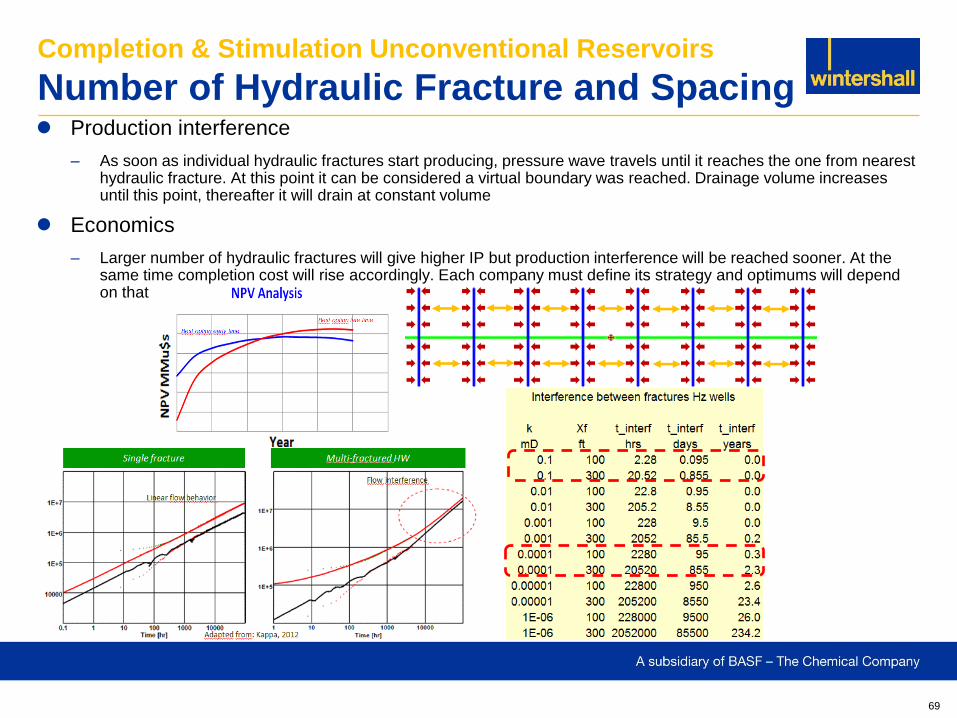
Production interference
– As soon as individual hydraulic fractures start producing, pressure wave travels until it reaches the one from nearest hydraulic fracture. At this point it can be considered a virtual boundary was reached. Drainage volume increases until this point, thereafter it will drain at constant volume
Economics
– Larger number of hydraulic fractures will give higher IP but production interference will be reached sooner. At the same time completion cost will rise accordingly. Each company must define its strategy and optimums will depend on that
Completion & Stimulation Unconventional Reservoirs
Number of Hydraulic Fracture and Spacing
70
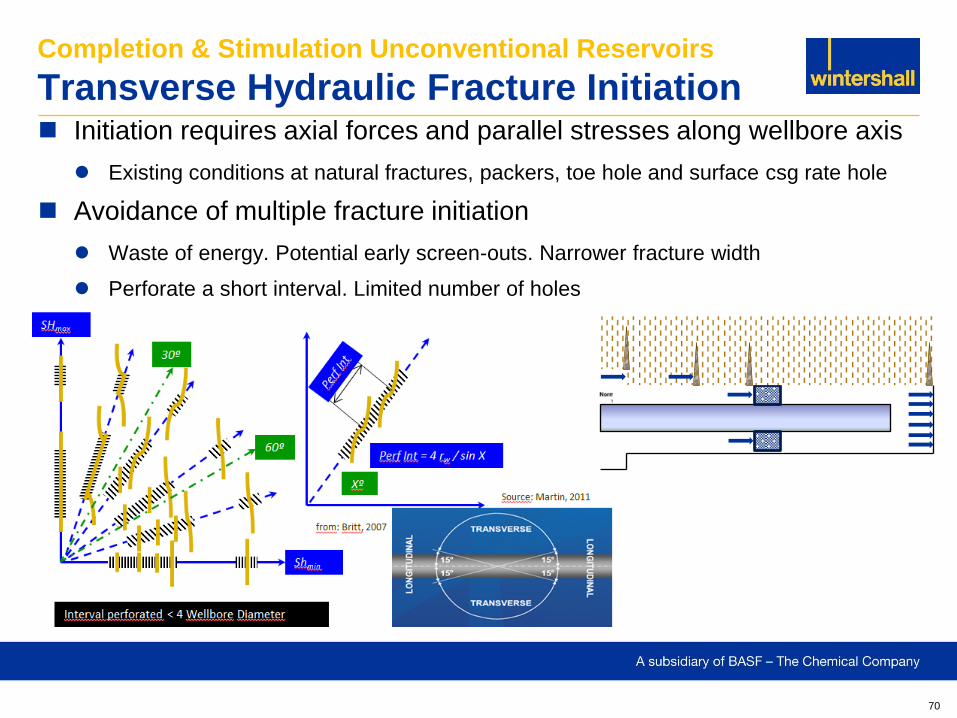
Initiation requires axial forces and parallel stresses along wellbore axis
Existing conditions at natural fractures, packers, toe hole and surface csg rate hole
Avoidance of multiple fracture initiation
Waste of energy. Potential early screen-outs. Narrower fracture width
Perforate a short interval. Limited number of holes
Completion & Stimulation Unconventional Reservoirs
Transverse Hydraulic Fracture Initiation
71
Completion & Stimulation Unconventional Reservoirs
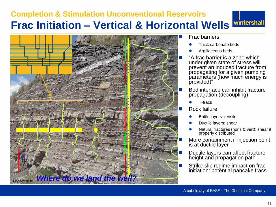
Frac Initiation – Vertical & Horizontal Wells Frac barriers
Thick carbonate beds
Argillaceous beds
“A frac barrier is a zone which under given state of stress will prevent an induced fracture from propagating for a given pumping parameters (how much energy is provided)”
Bed interface can inhibit fracture propagation (decoupling)
T-fracs
Rock failure
Brittle layers: tensile
Ductile layers: shear
Natural fractures (horiz & vert): shear if properly distributed
More containment if injection point is at ductile layer
Ductile layers can affect fracture height and propagation path
Strike-slip regime impact on frac initiation: potential pancake fracs
UBA’s website
Gale, 2014
Where do we land the well?
72
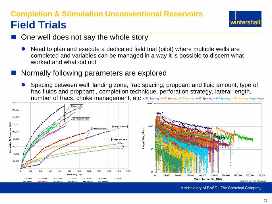
One well does not say the whole story
Need to plan and execute a dedicated field trial (pilot) where multiple wells are completed and variables can be managed in a way it is possible to discern what worked and what did not
Normally following parameters are explored
Spacing between well, landing zone, frac spacing, proppant and fluid amount, type of frac fluids and proppant , completion technique, perforation strategy, lateral length, number of fracs, choke management, etc
Completion & Stimulation Unconventional Reservoirs
Field Trials
73
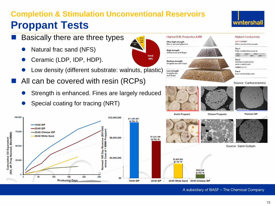
Basically there are three types
Natural frac sand (NFS)
Ceramic (LDP, IDP, HDP).
Low density (different substrate: walnuts, plastic)
All can be covered with resin (RCPs)
Strength is enhanced. Fines are largely reduced
Special coating for tracing (NRT)
Completion & Stimulation Unconventional Reservoirs
Proppant Tests
Source: Saint-Gobain
Source: Carboceramics
74
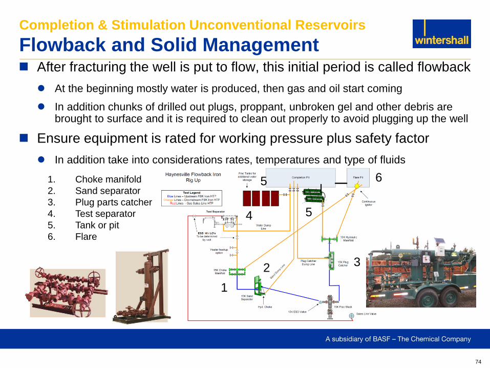
After fracturing the well is put to flow, this initial period is called flowback
At the beginning mostly water is produced, then gas and oil start coming
In addition chunks of drilled out plugs, proppant, unbroken gel and other debris are brought to surface and it is required to clean out properly to avoid plugging up the well
Ensure equipment is rated for working pressure plus safety factor
In addition take into considerations rates, temperatures and type of fluids
Completion & Stimulation Unconventional Reservoirs
Flowback and Solid Management
1. Choke manifold
2. Sand separator
3. Plug parts catcher
4. Test separator
5. Tank or pit
6. Flare
1
5
6
4
3 2
5
75
Completion & Stimulation Unconventional Reservoirs
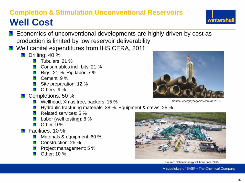
Well Cost Economics of unconventional developments are highly driven by cost as
production is limited by low reservoir deliverability
Well capital expenditures from IHS CERA, 2011 Drilling: 40 %
Tubulars: 21 %
Consumables incl. bits: 21 %
Rigs: 21 %. Rig labor: 7 %
Cement: 9 %
Site preparation: 12 %
Others: 9 %
Completions: 50 % Wellhead, Xmas tree, packers: 15 %
Hydraulic fracturing materials: 38 %. Equipment & crews: 25 %
Related services: 5 %
Labor (well testing): 8 %
Other: 9 %
Facilities: 10 % Materials & equipment: 60 %
Construction: 25 %
Project management: 5 %
Other: 10 %
Source: energiaynegocios.com.ar, 2013
Source: platinumenergysolutions.com, 2013
76
Completion & Stimulation Unconventional Reservoirs
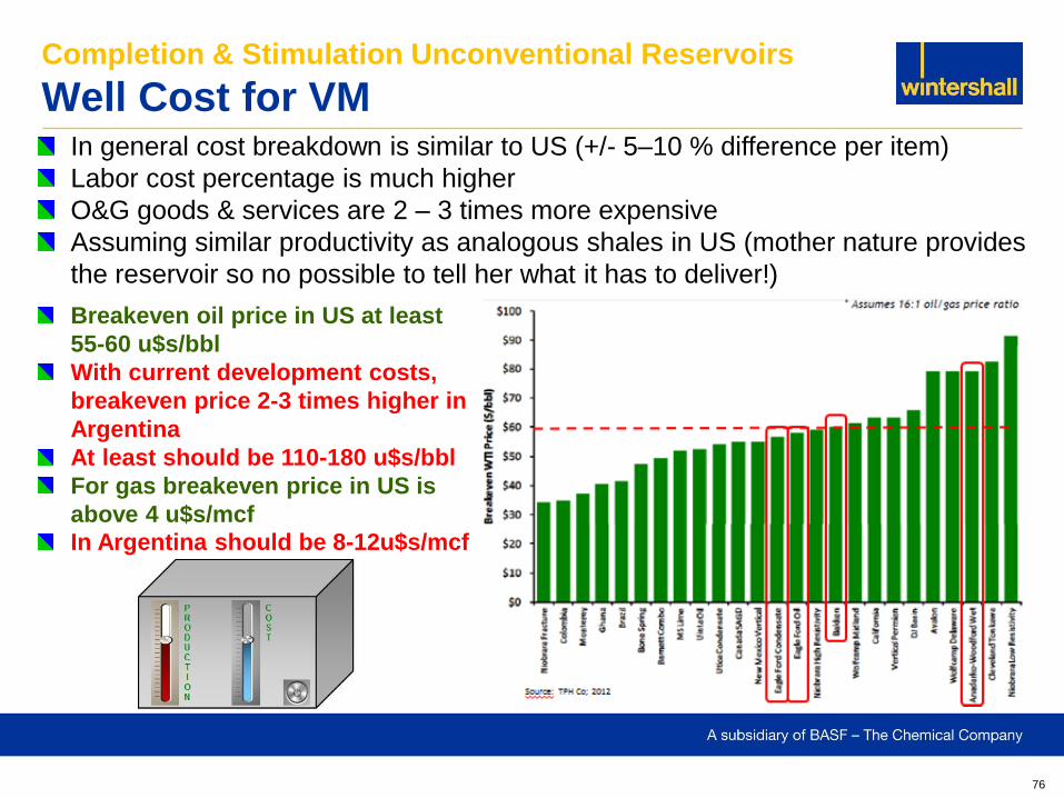
Well Cost for VM In general cost breakdown is similar to US (+/- 5–10 % difference per item)
Labor cost percentage is much higher
O&G goods & services are 2 – 3 times more expensive
Assuming similar productivity as analogous shales in US (mother nature provides
the reservoir so no possible to tell her what it has to deliver!)
Breakeven oil price in US at least
55-60 u$s/bbl
With current development costs,
breakeven price 2-3 times higher in
Argentina
At least should be 110-180 u$s/bbl
For gas breakeven price in US is
above 4 u$s/mcf
In Argentina should be 8-12u$s/mcf
77
Completion & Stimulation Unconventional Reservoirs
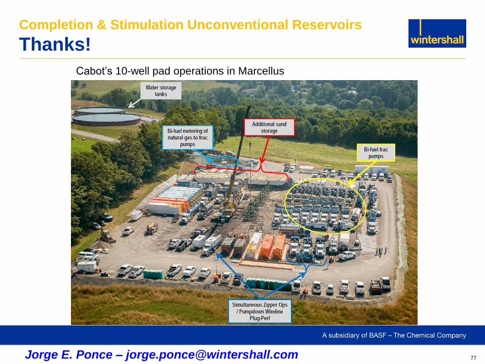
Thanks!
Cabot’s 10-well pad operations in Marcellus
Jorge E. Ponce – [email protected]
78
Completion & Stimulation Unconventional Reservoirs
Food for Thought
Insanity: “…doing the same thing over and over again
and expecting different results…”


![Reservoir Engineering Aspects of Unconventional Reservoirs · 2015. 7. 8. · Orientation: Reservoir Engineering Aspects of Unconventional Reservoirs [2/2] Slide — 4. SPEE Lunch](https://img.pdfslide.us/doc/110x75/5fe8b84b2cccc74fed2eb991/reservoir-engineering-aspects-of-unconventional-reservoirs-2015-7-8-orientation.jpg)