Embed Size (px)
Citation preview

Unconventional Reservoirs
Jorge Ponce June 14th, 2013

Disclaimer, Copyright and Legal Notice
I do not make any warranty, express or implied, or assume any legal liability or responsibility for the accuracy, completeness, or usefulness of any information, apparatus, product, or process disclosed, or represent that its use would not infringe privately owned rights. Every picture or drawing used to describe a tool or system has been only utilized for illustration purposes and has been properly identified in the reference section and remains as a property of their respective owners / authors. Reference herein to any specific commercial product, process, or service by trade name, trademark, manufacturer, or otherwise does not necessarily constitute or imply its endorsement, recommendation, or favoring by myself. The views and opinions of the author expressed herein do not necessarily state or reflect the company where the author works for. Further, while I have taken all reasonable steps to ensure that everything published is accurate it does not accept any responsibility for any errors or resulting loss or damage whatsoever or howsoever caused and readers and practitioners have the responsibility to thoroughly check these aspects for themselves. This presentation or any of its contents may be reproduced, copied, modified or adapted, subject to inclusion of presentation’s title, author, date and copyright notice of other authors.

Why do we need Unconventional Reservoirs (UN)?
World daily life is built on different types of energy
Despite economy suffers ups and downs as a general trend energy demand goes up
Growing population and income per capita
BRICS conglomerate’s economy is highly energy demanding
Modern life depends basically on electricity and/or natural gas
Globalization has incremented traveling around the globe, thus increasing different types of fuel demand for air, sea and ground transportation
Conventional sources are running out
No more giants like Saudi Arabia
Large reserves in environmentally sensitive areas (Alaska, Florida, Pacific)
Subsalt discoveries in Brazil - expensive
Counterpart in Africa – expensive
Selfsufficiency is critical for certain countries under the world political scenario
Renewables (Wind, Solar, Biodiesel, Biomass, Geothermal, Nuclear, Hydropower, Marine power, Anaerobic digestion/algae) are not enough to fill in the gap of total energy demand

Is Argentina an Exception?
Demand trend of gas and oil goes up
Oil and gas production decreases to reach a crossover point
Need to import energy
Lost of selfsufficiency
2/3 of the electricity is generated from fossil fuels basically natural gas and gas oil
Other sources can not meet demand gap

The Size of the Treasure – Worth it?
Top 10 countries with technically recoverable shale oil and gas resources
Source: EIA, 2013 Source: ICEPT, 2012
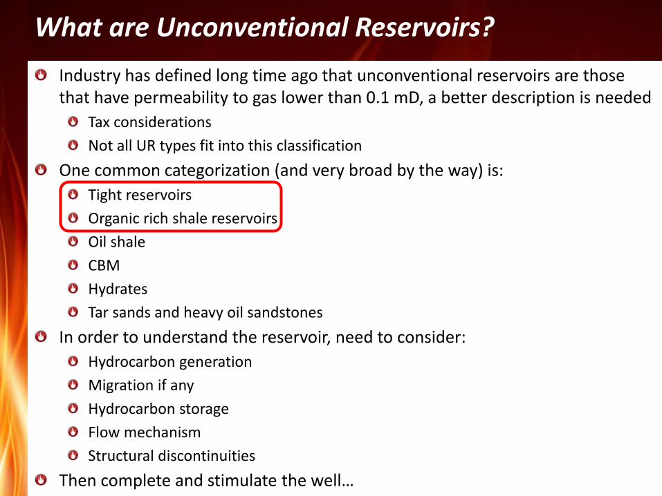
What are Unconventional Reservoirs?
Industry has defined long time ago that unconventional reservoirs are those that have permeability to gas lower than 0.1 mD, a better description is needed
Tax considerations
Not all UR types fit into this classification
One common categorization (and very broad by the way) is:
Tight reservoirs
Organic rich shale reservoirs
Oil shale
CBM
Hydrates
Tar sands and heavy oil sandstones
In order to understand the reservoir, need to consider:
Hydrocarbon generation
Migration if any
Hydrocarbon storage
Flow mechanism
Structural discontinuities
Then complete and stimulate the well…
Tight Reservoirs (TR)
By definition, reservoirs with permeability less than 0.1 mD to gas. Really ambiguous
Actually tight oil and tight gas reservoirs are being developed
Hydrocarbons were generated at another source rock. Negligible organic material
Migration occurs and hydrocarbons get trapped due to seals or extremely low permeability barriers
If hydrocarbons migrate there is enough permeability to gas to flow and porosity to store them, ergo:
Flow mechanism: Darcy´s flow
Storage: pore volume
Rock types:
Sandstones: mostly quartz with clays and cementitious materials
Carbonates: low to very low permeability carbonates
Igneous and metamorphic rocks like basement
Requires massive hydraulic fractures to get commercial rates
Seal rock
Tight rock
Source rock
Tight reservoirs
0 25 50 75
Organic content % wt
Poral system
Mineral frame
Clay & cement
Source: adapted from Franco, 2011

Organic Rich Shale Reservoirs (SR)
Hydrocarbons are generated, stored and trapped in the same rock
Definition of shale based on grain size rather than mineralogy composition
Due to its extremely low permeability, hydrocarbons did not have enough time to migrate
As there is low permeability there is also low porosity
Presence of organic material not converted to hydrocarbon (kerogen)
Flow mechanism: Darcy´s flow in the matrix, Fick´s law in the organic portion
Storage: pore volume and adsorption in the organic material
Rock types:
Siliceous
Carbonaceous
Argillaceous
Source, trap & reservoir rock
Organic rich shale reservoirs
0 25 50 75
Organic content % wt
Source: Woodford shale. Bustin, 2009
Source: SPE 115258
Source: Barnet. SPE 124253
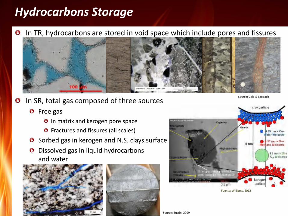
Hydrocarbons Storage
In TR, hydrocarbons are stored in void space which include pores and fissures
In SR, total gas composed of three sources
Free gas
In matrix and kerogen pore space
Fractures and fissures (all scales)
Sorbed gas in kerogen and N.S. clays surface
Dissolved gas in liquid hydrocarbons and water
Source: Bustin, 2009
Source: Loucks, 2009
Source: Gale & Laubach
Fuente: Williams, 2012
Fuente: Pitman, 2011

The “NANO” World in Perspective
Fuente: Nelson, 2009
1 µm = 1 E-06 m = 0.001 mm 1nm = 0.001 µm = 1E-09 m 1 Angstrom = 0.1 nm
Conventional Oil & Gas Dpore ≥ 1 µm K ≥ 1 mD
Tight Reservoirs 1 µm ≥ Dpore ≥ 10-3 µm 1 mD ≥ K ≥ 1 µD
Shale Reservoirs 1 µm ≥ Dpore ≥ 10-3 µm 10-9 mD ≥ K ≥ 10-3 mD
Human hair 50 – 100 µm
Fuente: Jarvie, 2008

Reservoir Permeability & Flow Capacity
1E-06 1E-05 1E-04 0.001 0.01 0.1 1 1000 10 100
Unconventional
Ara
bic
car
bo
nat
es
Ber
ea s
and
sto
ne
Cla
ss “
G”
cem
ent
Co
nst
ruct
ion
bri
ck
Exte
nd
ed s
lurr
y
Low
po
rosi
ty s
lurr
y
Organic shales Tight reservoirs
Dry Gas / Darcy Flow
P_res 5500 psi
BHFP 1500 psi
BHT 200 ºF
SG_gas 0.65
Thickness 5 m
Qg \ K_gas 10 mD 1 mD 0.1 mD 0.01 mD
m3gpd 924,000 92,400 9,240 924
For dry gas, no commercial rates below 0.1 mD unless well is hydraulically fractured
If multiphase flow exists, gas production is much lower
In shales K<<0.1 mD, so matrix flow is extremely low. Need to have extremely large contact areas to get economical rates
Presence of natural fissures and fractures enhance fluid flow tremendously
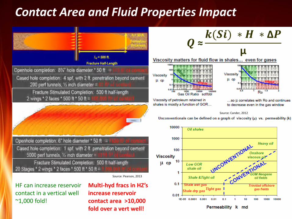
Contact Area and Fluid Properties Impact
Source: Cander, 2012
HF can increase reservoir contact in a vertical well ~1,000 fold!
Multi-hyd fracs in HZ’s increase reservoir contact area >10,000 fold over a vert well!
Source: Pearson, 2013
𝑸 ≈𝒌(𝑺𝒊) ∗ 𝑯 ∗ ∆𝑷
µ

Production in Shale Reservoirs
If permeability is less than 5E-5 mD gas only flows within the SRV to HF’s
No flow beyond frac tip in 30 years. Effect is magnified when oil is produced
Linear and bilinear flow
Flow area is restricted in shales. The only thing we can do is try to activate part of the reservoir (SRV) if appropiate conditions are found. Frac interference
Darcy, Knudsen and diffusive flow. Adsorbed and free gas
Unstimulated volume
SRV
But Xf,eff= D/2 !
k, mD Xf, ft / m t_int, hr T_int, días T_int,
años
0.1 100 / 30.5 2.28 0.095 ~
0.1 300 / 91.4 20.52 0.855 ~
0.001 100 / 30.5 228 9.5 ~
0.001 300 / 91.4 2052 85.5 0.2
0.00001 100 / 30.5 22800 950 2.6
0.00001 300 / 91.4 205200 8550 23.4
Fuente: Tella, 2011
Linear - Frac
Bi-linear
Linear - Form
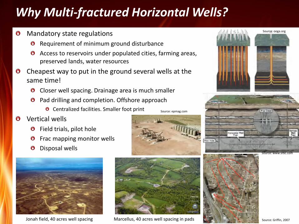
Why Multi-fractured Horizontal Wells?
Mandatory state regulations
Requirement of minimum ground disturbance
Access to reservoirs under populated cities, farming areas, preserved lands, water resources
Cheapest way to put in the ground several wells at the same time!
Closer well spacing. Drainage area is much smaller
Pad drilling and completion. Offshore approach
Centralized facilities. Smaller foot print
Vertical wells
Field trials, pilot hole
Frac mapping monitor wells
Disposal wells
Jonah field, 40 acres well spacing Marcellus, 40 acres well spacing in pads Source: Griffin, 2007
Source: www.srbc.com
Source: epmag.com
Source: ooga.org

Well Construction – Factory Mode
Source: Griffin, 2007
Source: SA Express News
Source: Thomson, 2012
Pad Drilling Casing & Cementing
Source: Baker Hughes
Perforating
Hydraulic Fracturing Operations at Pad Site
Frac Head
Source: EXCO, 2012

TR Completion and Stimulation
By reservoir type
Multiple stacked layers: multi hydraulically fractured vertical wells.
Single or double individual reservoirs: mostly horizontal wells. First wells must be vertical for gathering information. Multiple hydraulic fractures
By completion type
Cased and un-cemented completions. Packers for zonal or compartment isolation
Cased hole: cemented
from: S. Jerez Vera. MsC. TAM
from: Questar presentation
Kgas Por Sw Hnet
10 HF1
HF2
HF3
0.004 5.2 15
15 0.07 8.9 17
18 0.03 6.7 22
Adapted from: Red Oak well log
Kgas Por Sw Hnet
30 0.06 6.2 20

SR Completion and Stimulation
By reservoir type
Single reservoir: multi hydraulically fractured horizontal wells. Few verticals at beginning for gathering information
Double individual reservoirs: dual horizontal wells with multiple hydraulic fractures
By completion type
Cased and un-cemented completions. Packers for zonal or compartment isolation
Cased hole: cemented
from: www.srbc.net
Source: PackersPlus
Adapted from: PackersPlus Source: PackersPlus

Multi Stage Completions
Multiples technolgies are available but market dominated by three technologies:
Plug & Perf. 70 – 75 % of wells are completed using this technology
Ball operated frac ports. 20 – 25 % of wells. Sometimes this and previous method are combined to get more stages
CT based techniques. Less than 5 % of wells uses this technology
Abrassive jet perforating. Sand or composite plugs to isolate stages
Pumping mainly donw thru annulus but also possible thru tbg if diameter is big enough
Packer and anchor
CT activated frac sleeves
Plug & Perf – Unlimited stages Frac Ports – 40 stages max CT based techniques – Unlimited stages
Source: Halliburton
Source: Halliburton Source: Weatherford
source: Baker Oil Tools
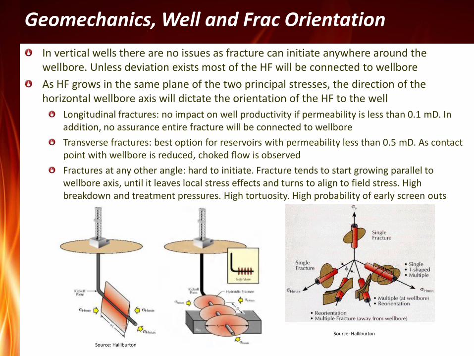
Geomechanics, Well and Frac Orientation
In vertical wells there are no issues as fracture can initiate anywhere around the wellbore. Unless deviation exists most of the HF will be connected to wellbore
As HF grows in the same plane of the two principal stresses, the direction of the horizontal wellbore axis will dictate the orientation of the HF to the well
Longitudinal fractures: no impact on well productivity if permeability is less than 0.1 mD. In addition, no assurance entire fracture will be connected to wellbore
Transverse fractures: best option for reservoirs with permeability less than 0.5 mD. As contact point with wellbore is reduced, choked flow is observed
Fractures at any other angle: hard to initiate. Fracture tends to start growing parallel to wellbore axis, until it leaves local stress effects and turns to align to field stress. High breakdown and treatment pressures. High tortuosity. High probability of early screen outs
Source: Halliburton
Source: Halliburton
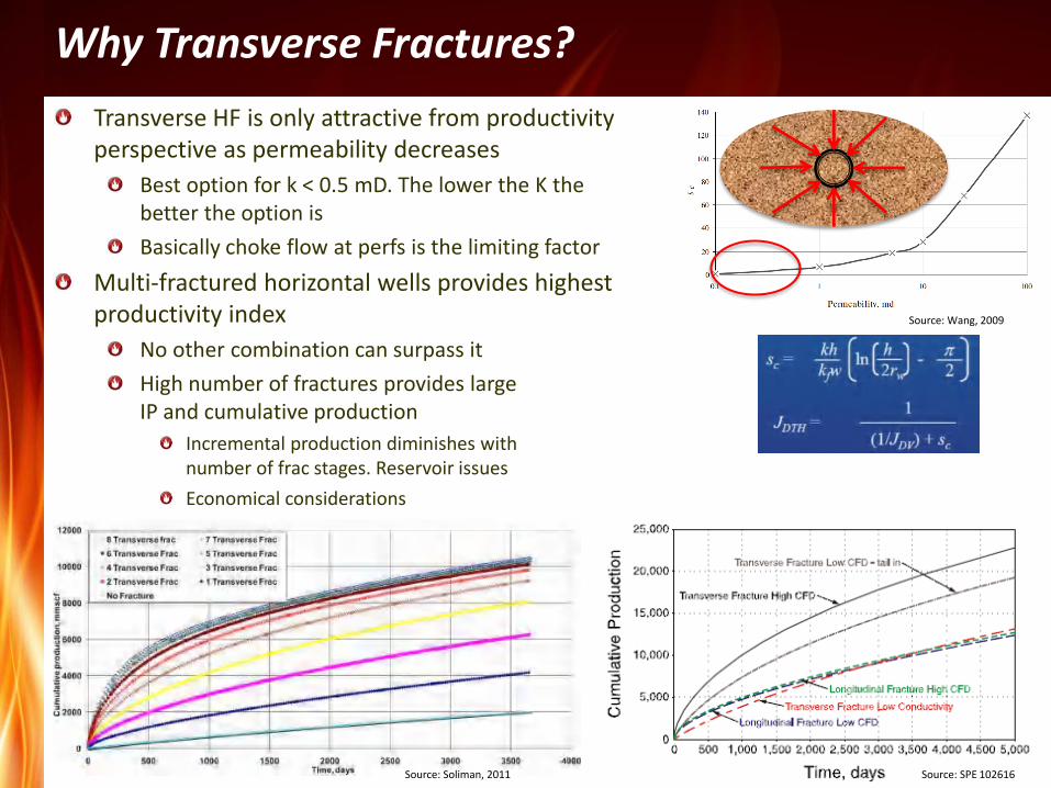
Why Transverse Fractures?
Transverse HF is only attractive from productivity perspective as permeability decreases
Best option for k < 0.5 mD. The lower the K the better the option is
Basically choke flow at perfs is the limiting factor
Multi-fractured horizontal wells provides highest productivity index
No other combination can surpass it
High number of fractures provides large IP and cumulative production
Incremental production diminishes with number of frac stages. Reservoir issues
Economical considerations
Source: SPE 102616
Source: Wang, 2009
Source: Soliman, 2011

Frac Design – General Guidelines
Frac fluid system depends mainly on reservoir type and density of fissures TR: linear, X-linked or hybrid designs
SR: mainly slick water
Fracturing rate dictated by reservoir type TR: proppant transport governed by viscosity
SR: velocity is the transport mechanism
Frac volume TR: contacted area is the main factor
SR: SRV is the key factor. Larger is better
Proppant concentration TR: low to medium. Generally 4 - 5 ppg maximum
SR: low. No more than 2 ppg as final conc in gas, for oil higher concentartions
Proppant mesh size TR: governed by frac width
SR: governed by frac width and proppant transport capability of frac fluid
from: SPE 115258
Brittleness Fluid
system
Fluid
viscosity
Natural
fractures
Frac
rate
Proppant
conc
Frac fluid
volume
Proppant
volume
Fracture
geometry
Frac width
Brittle SWF Low Severe High Low High Low Network Very narrow
SWF Low
Hybrid Low/medium
Linear Medium
Foam Medium
X-Linked High
Ductile X-Linked High No fracs Low High Low High Two-wing Narrow

Stimulation Success and Optimization
The only way of being successful and continue improving the development of UR is to push the limits of existing technologies and apply new ones. Cost driven development!
Verify if what you planned is what you got. Evaluate new technologies. Check assumptions, calibrate and test changes. Currently four major technologies are used:
Microseismic
Tracers (chemicals and radioactive)
Production logs
Production transient and decline analyses
Source: epmag.com
Source: Miller
Source: SLB
Source: Blasingame, 2010

Production Forecasting and Reserves Estimation
Production decline analysis Base relations: Arps’s eq
Only valid for pseudosteady state (boundary limits were reached!!!)
In practice most of the time actual b>1
Physical vs mathematical problem b> 1 just indication of transient flow
No limits reached = not possible to apply the methodology. Use better methods!
If b>1 at t= long enough, reserves are infinite!
Decline behavior Strong decline during first years
Source: Petrohawk, 2011
Source: Blasingame, 2013
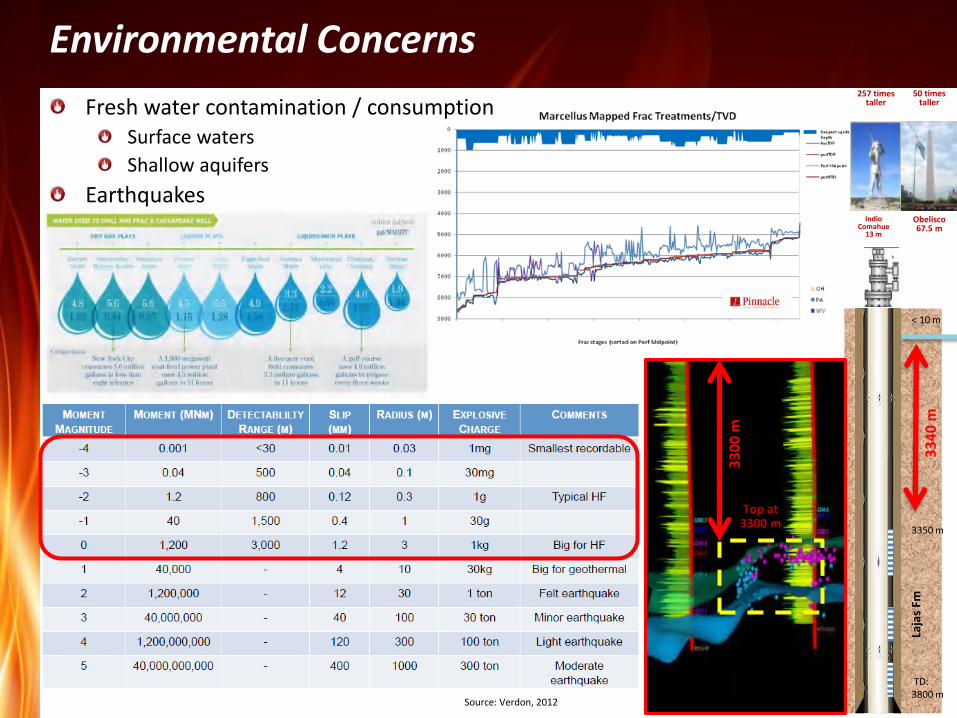
Environmental Concerns
Fresh water contamination / consumption Surface waters
Shallow aquifers
Earthquakes
TD: 3800 m
3350 m
Laja
s Fm
< 10 m
33
40
m
Obelisco 67.5 m
Indio Comahue
13 m
257 times taller
50 times taller
Top at 3300 m
33
00
m
Source: Verdon, 2012

Environmental Concerns – Cont´d
Tertiary Shear Zone
Channel Complex Incision
Strong complaints that frac additives
are highly contaminating
Same products used fo medicines,
foods, cosmetics, home cleaning
products, etc
Source: www.aplng.com.au
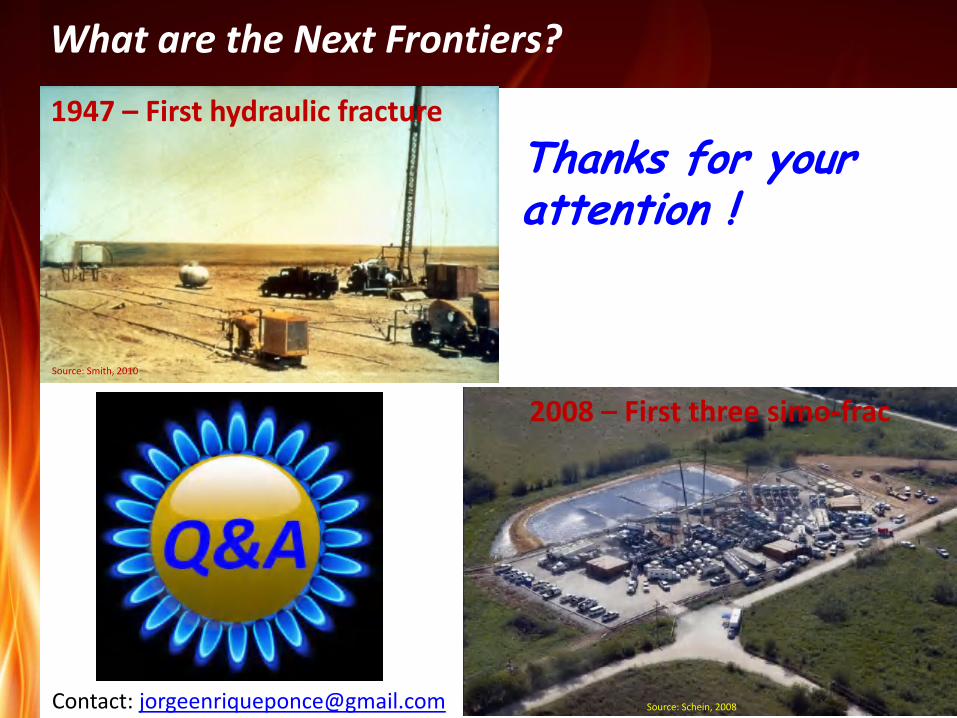
What are the Next Frontiers?
Tertiary Shear Zone
Channel Complex Incision
Thanks for your attention !
1947 – First hydraulic fracture
2008 – First three simo-frac
Source: Smith, 2010
Source: Schein, 2008 Contact: [email protected]
![Reservoir Engineering Aspects of Unconventional Reservoirs · 2015. 7. 8. · Orientation: Reservoir Engineering Aspects of Unconventional Reservoirs [2/2] Slide — 4. SPEE Lunch](https://img.pdfslide.us/doc/110x75/5fe8b84b2cccc74fed2eb991/reservoir-engineering-aspects-of-unconventional-reservoirs-2015-7-8-orientation.jpg)