Embed Size (px)
Citation preview
7/21/2019 Comparison of the Rayleigh and Nakagami Fading Channels MIMO Multicarrier System
http://slidepdf.com/reader/full/comparison-of-the-rayleigh-and-nakagami-fading-channels-mimo-multicarrier-system 1/4
IEEE SIGNAL PROCESSING LETTERS, VOL. 19, NO. 12, DECEMBER 2012 793
A Method for Broadband Full-Duplex MIMO RadioYingbo Hua , Fellow, IEEE , Ping Liang, Yiming Ma, Ali Cagatay Cirik, and Qian Gao
Abstract— We present a time-domain transmit beamforming
(TDTB) method for self-interference cancelation (SIC) at the radiofrequency (RF) frontend of the receivers on broadband full-duplexMIMO radios. It is shown that the conventional frequency-domaintransmit beamforming (FDTB) method along with the orthogonal
frequency division multiplexing (OFDM) framework does notgenerally perform SIC in the prefix region of a transmitted frame.A hardware based test of the TDTB method shows a 50 dB SICover a bandwidth of 30 MHz.
Index Terms— Full-duplex radar, full-duplex wireless communi-cation, single channel full-duplex.
I. I NTRODUCTION
A full-duplex radio (or radio station) is defined as a radiofrequency (RF) transceiver that can transmit and receive
signals at the same time and same frequency. All currentlydeployed radios for wireless communications are half-duplexwhich transmit and receive signals in two separate/orthogonalchannels. A full-duplex radio can have twice as high spec-tral ef ficiency as a half-duplex radio. Possible applicationsof full-duplex radios include wireless base stations, wirelessrelays and personal-area wireless devices.
A fundamental issue for a full-duplex radio is known as self-interference cancelation (SIC). When a full-duplex radio trans-mits, it causes a strong self-interference to its receiver. There arethree basic approaches to reduce the self-interference. The first
is to apply RF attenuation between the transmit (Tx) antennasand the receive (Rx) antennas on the same radio unit. This can be done by increasing the distances between the Tx and Rx an-tennas, using RF absorbing materials, and/or designing and uti-lizing antenna null angles. For many practical settings, this ap- proach can achieve 40–60 dB reduction of self-interference. Butat the same time, the transmitted signal from a radio can be upto 100 dB stronger than a desired signal from a remote node.This approach alone typically still leaves a too large amountof self-interference. The second approach is baseband-only SICat the receiver side, as in [1], which cancels the self-interfer-ence after the self-interference has been received and demodu-lated into baseband. When the self-interference is much stronger
than the desired signal, this approach suffers from saturation of the analog-to-digital converter (ADC) of the receiver, i.e., thedesired signal is corrupted by an additional quantization noise
Manuscript received July 24, 2012; revised September 18, 2012; acceptedSeptember 25, 2012. Date of publication October 02, 2012; date of current ver-sion October 08,2012. This work wassupportedin part bya DoDDURIPGrant.The associate editor coordinating the review of this manuscript and approvingit for publication was Prof. Kostas D. Berberidis.
The authors are withDepartmentof Electrical Engineering, Universityof Cal-ifornia, Riverside, CA, 92521 USA (e-mail: [email protected]; [email protected]; [email protected]; [email protected]; [email protected]).
Color versions of one or more of the figures in this paper are available onlineat http://ieeexplore.ieee.org.
Digital Object Identifier 10.1109/LSP.2012.2221710
power which can be shown to be proportional to the power ratio
of the interference over the desired signal.The third approach, a focus of this paper, is to use transmit
beamforming for SIC at the RF frontend of receivers. To-gether with the first two approaches, the third appears to holdthe promise to make full-duplex radio a reality. The recentworks on transmit beamforming for full-duplex radio are allformulated in the frequency-domain, e.g., see [2]–[6] and thereferences therein. We call these methods the frequency-do-main transmit beamforming (FDTB). The experimental worksshown in [7]–[12] either applied a FDTB method or assumedfrequency-flat channels.
We will show that a FDTB method, when (typically) imple-mented with OFDM for broadband applications, does not gener-
ally remove the self-interference on a frame received from a re-mote node in a time region corresponding to the prefix region of a frame transmitted from the local node. To ensure the prefix re-gion of the transmitted frame not to coincide with anyuseful partof the received frame is dif ficult for most full-duplex operations.The paper [12] did not recognize this problem although they re- ported dif ficulties with reception after transmission starts.
In this paper, we present a time-domain transmit beam-forming (TDTB) method for broadband SIC at the RF frontend.The TDTB waveforms can be directly implemented at thecircuit level without costly transformations between time andfrequency domains at a sampling rate much higher than the baud rate applied for OFDM. A full-duplex radio based on
TDTB removes self-interference at all time, which allowsasynchronous full-duplex. We will also present a hardware based experimental result of TDTB for SIC.
II. CONDITION FOR SIC AT RF FRONTEND
We consider a generic MIMO radio unit equipped withRF receivers and RF signal generators/transmitters. Amongall generators, there ar e primary generatorsand auxiliary generators. The primary generators are used totransmit up to independent streams of data to a remote node.The auxiliary generators are used to generate RF waveforms for SIC at the RF frontend of the receivers on the same radio.
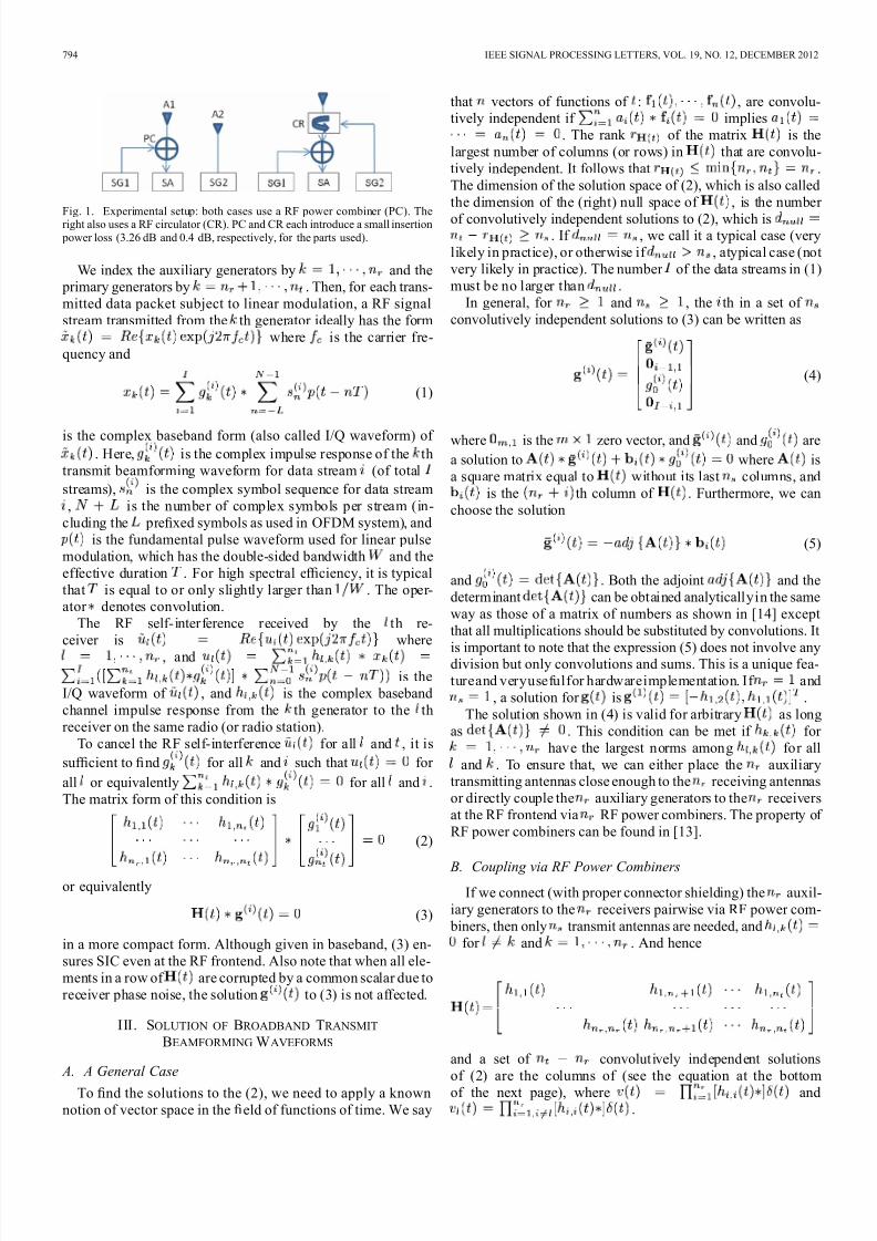
The primary gener ators can be directly connected to pri-mary transmit antennas, the auxiliary generators to auxiliarytransmit antennas, and the receivers to receive antennas.While the spacing between the primary transmit antennas andthat between the receive antennas should be large enough for a high diversity, the spacing between an auxiliary transmit an-tenna and a receive antenna can be small for large coupling. For the strongest coupling, the auxiliary generators can be directlyconnected pairwise to the receivers at the RF frontend using RF power combiners. Furthermore, if a primary transmit antennaand a receive antenna have overlapping beam patterns in thedirections of interest, they can be merged into one via a RF cir-culator. See Fig. 1 later. The following discussion is valid for
any of the above situations.
1070-9908/$31.00 © 2012 IEEE
7/21/2019 Comparison of the Rayleigh and Nakagami Fading Channels MIMO Multicarrier System
http://slidepdf.com/reader/full/comparison-of-the-rayleigh-and-nakagami-fading-channels-mimo-multicarrier-system 2/4
794 IEEE SIGNAL PROCESSING LETTERS, VOL. 19, NO. 12, DECEMBER 2012
Fig. 1. Experimental setup: both cases use a RF power combiner (PC). Theright also uses a RF circulator (CR). PC and CR each introduce a small insertion power loss (3.26 dB and 0.4 dB, respectively, for the parts used).
We index the auxiliary generators by and the primary generators by . Then, for each trans-mitted data packet subject to linear modulation, a RF signalstream transmitted from the th generator ideally has the form
where is the carrier fre-quency and
(1)
is the complex baseband form (also called I/Q waveform) of . Here, is the complex impulse response of the th
transmit beamforming waveform for data stream (of total
streams), is the complex symbol sequence for data stream, is the number of complex symbols per stream (in-
cluding the prefixed symbols as used in OFDM system), andis the fundamental pulse waveform used for linear pulse
modulation, which has the double-sided bandwidth and theeffective duration . For high spectral ef ficiency, it is typicalthat is equal to or only slightly larger than . The oper-ator denotes convolution.
The RF self-interference received by the th re-ceiver is where
, and
is theI/Q waveform of , and is the complex basebandchannel impulse response from the th generator to the threceiver on the same radio (or radio station).
To cancel the RF self-interference for all and , it is
suf ficient to find for all and such that for
all or equivalently for all and .The matrix form of this condition is
(2)
or equivalently
(3)
in a more compact form. Although given in baseband, (3) en-sures SIC even at the RF frontend. Also note that when all ele-ments in a row of are corrupted by a common scalar due toreceiver phase noise, the solution to (3) is not affected.
III. SOLUTION OF BROADBAND TRANSMIT
BEAMFORMING WAVEFORMS
A. A General Case
To find the solutions to the (2), we need to apply a knownnotion of vector space in the field of functions of time. We say
that vectors of functions of : , are convolu-tively independent if implies
. The rank of the matrix is thelargest number of columns (or rows) in that are convolu-tively independent. It follows that .The dimension of the solution space of (2), which is also calledthe dimension of the (right) null space of , is the number
of convolutively independent solutions to (2), which is. If , we call it a typical case (very
likely in practice), or otherwise if , atypical case (notvery likely in practice). The number of the data streams in (1)must be no larger than .
In general, for and , the th in a set of convolutively independent solutions to (3) can be written as
(4)
where is the zero vector, and and are
a solution to where isa square matrix equal to without its last columns, and
is the th column of . Furthermore, we canchoose the solution
(5)
and . Both the adjoint and thedeterminant can be obtained analyticallyin the sameway as those of a matrix of numbers as shown in [14] exceptthat all multiplications should be substituted by convolutions. It
is important to note that the expression (5) does not involve anydivision but only convolutions and sums. This is a unique fea-tureand veryusefulfor hardwareimplementation. If and
, a solution for is .The solution shown in (4) is valid for arbitrary as long
as . This condition can be met if for have the largest norms among for all
and . To ensure that, we can either place the auxiliarytransmitting antennas close enough to the receiving antennasor directly couple the auxiliary generators to the receiversat the RF frontend via RF power combiners. The property of RF power combiners can be found in [13].
B. Coupling via RF Power Combiners
If we connect (with proper connector shielding) the auxil-iary generators to the receivers pairwise via RF power com- biners, then only transmit antennas are needed, and
for and . And hence
and a set of convolutively independent solutionsof (2) are the columns of (see the equation at the bottomof the next page), where and
.
7/21/2019 Comparison of the Rayleigh and Nakagami Fading Channels MIMO Multicarrier System
http://slidepdf.com/reader/full/comparison-of-the-rayleigh-and-nakagami-fading-channels-mimo-multicarrier-system 3/4
HUA et al.: METHOD FOR BROADBAND FULL-DUPLEX MIMO RADIO 795
C. Issues of the Frequency-Domain Solution
Applying the Fourier transform to (3) yields
(6)
where and are Fourier transforms of and
respectively. The solutions to (6) at a given frequencyare the conventional form of the transmit beamforming vectors.
For any fixed , the basis vectors of the null space of can be, and are commonly, computed numerically. The Fourier transform of shown in (4) is also a valid solution to (6).But they are generally not orthogonal with each other. Further-more, the condition (i.e., not a zero function
of ) does not necessarily imply for all .Clearly, from the aspects of computation and implementation,the frequency-domain transmit beamforming (FDTB) and thetime-domain transmit beamforming (TDTB) are quite different.
All the prior works shown in [2]–[12] use the frequency-do-main solutions except [10] where allpass channels are assumed.
The frequency-domain solutions are naturally suited for narrow- band applications for which the channel frequency responsesmust be completely flat within the bandwidth of interest arounda given . For broadband applications of the frequency-domainsolution, an OFDM-based system supporting multiple subcar-riers provides a natural platform. In [12], the authors appliedthe frequency-domain solution (assuming ) toan OFDM system with 64 subcarriers spanning 10 MHz band-width. However, as shown next, the frequency-domain solutionwith OFDM does not in general remove the self-interference atthe RF frontend in the prefix region of a transmitted packet.
Consider the case of and the use of RF power combiner for cancelation. Denote the baud-rate
channel response of the primary interference channel byfor and the baud-rate
channel response of the interference cancelation channel bywhere is the baud interval. (The
baud rate is smaller than the sampling rate mentioned later.) For simplicity, we assume that the channel between the auxiliarygenerator and the receiver is completely flat, i.e., .We will show below that the power of the self-interference inthe prefix region of the transmitted frame is
(7)
where is the power of the signal transmitted by the primarytransmitter, and is the length of the prefix as determined bythe OFDM system standard (which should be the upper bound
on the maximum delay spread of all channels between radiosin a given environment). We have assumed here that there is agap of at least baud intervals between two adjacent OFDMframes transmitted by the primary transmitter. Otherwise, theself-interference in the prefix region is even stronger due to thecontribution from the previous frame. We see that if and only if for (i.e., if and only if the channel
frequency response between the primary transmitter and the re-ceiver is also completely flat over all subcarriers). Such a con-dition is dif ficult to hold to a precision required. The only co-ef ficient of the channel impulse response that contributes zerointerference is , which may or may not be the most dom-inant (depending on the channel environment between the pri-mary transmit antenna and the receive antenna).
The result (7) should also be useful for many (beyond full-duplex radios) broadband interference cancelation applicationsusing the OFDM-based FDTB method.
Proof of (7): Recall that the signal flow in an OFDM com-munication system has the following sequence of components:original symbols, IFFT, cyclic prefixing, RF modulation,
transmission, RF demodulation, sampling, prefix discarding,and FFT. Let be zero-mean and uncorrelatedsymbols to be transmitted from the radio in an OFDM frame.Its -point IFFT is , which are also zero-meanand uncorrelated. After -point cyclic prefixing, it becomes
. This sequence is modulated into a base- band waveform, then modulated into an RF waveform byan RF carrier and then transmitted by the primary trans-mitter. At the local receiver, after RF demodulation andthen baseband sampling (and before the stage of prefix-dis-carding and FFT), the interfering samples received by thelocal receiver in the prefix region of the transmitted frameare ;
For SIC, the auxiliary generator needs to transmit(concurrently with the primary generator) the following
pre-IFFT symbols:
where as in [12]. Applying IFFT
to these symbols yields ,, where denotes in modulo- .
Then, after cyclic-prefixing the sequence , the firstsamples to be transmitted by the auxiliary generator are
where . Since the channel fromthe auxiliary transmitter to the local receiver is assumed to beallpass, then the “net” self-interference at the local receiver in
the prefix region is
with
. With the definitionand , (7) is hence proved.
7/21/2019 Comparison of the Rayleigh and Nakagami Fading Channels MIMO Multicarrier System
http://slidepdf.com/reader/full/comparison-of-the-rayleigh-and-nakagami-fading-channels-mimo-multicarrier-system 4/4
796 IEEE SIGNAL PROCESSING LETTERS, VOL. 19, NO. 12, DECEMBER 2012
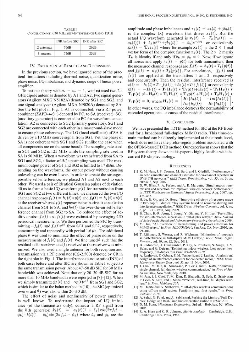
TABLE ICANCELATION OF A 30 MHz SELF-I NTERFERENCE USING TDTB
IV. EXPERIMENTAL R ESULTS AND DISCUSSIONS
In the previous section, we have ignored some of the prac-tical limitations including thermal noise, quantization noise, phase noise, I/Q imbalance, and dynamic range of linear power amplifier.
To test our theory with , we first used two 2.4GHz dipole antennas denoted by A1 and A2, two signal gener-ators (Agilent MXG N5182A) denoted by SG1 and SG2, andone signal analyzer (Agilent MXA N9020A) denoted by SA.See the left plot in Fig. 1. A1 is connected, via a RF power combiner (ZAPD-4-S+) denoted by PC, to SA (receiver). SG1(auxiliary generator) is connected to PC for waveform cance-
lation. A2 is connected to SG2 (primary generator). SG1 andSG2 are connected with each other in a master-and-slave modeto ensure phase coherency. The LO (local oscillator) of SA isdriven by a 10 MHz source signal from SG1. Yet, the phase of SA is not coherent with SG1 and SG2 (unlike the case whenall components are on the same board). The sampling rate usedin SG1 and SG2 is 125 MHz while the sampling rate used inSA is 50 MHz. When a waveform was transferred from SA toSG1 and SG2, a factor-of-5/2 upsampling was used. The max-imum output power of SG1 and SG2 is limited to 17 dBm. De- pending on the waveforms, the output power without causingunleveling can be even lower. In order to create the strongest possible self-interference, we placed A1 and A2 next to each
other. We used a pair of identical Gaussian pulses of deviation40 ns to form a basic I/Q waveform for transmission fromSG1 and SG2 at two different times, we measured the two I/Qchannel responses andat the receiver where represents the in-circuit cancelationchannel from SG1 to SA, and the over-the-air self-inter-ference channel from SG2 to SA. To reduce the effect of ad-ditive noise, and were estimated by averaging 250 periodical measurements. We then performed the SIC by trans-mitting and from SG1 and SG2, respectively,concurrently and repeatedly with period 1.6 . The additional phase was used to minimize the effect of phase noise on themeasurements of and . We fine tuned such that the
residual self-interference received at the receiver was min-imized. We also used a single antenna for both reception andtransmission via a RF circulator (CS-2.500) denoted by CR inthe right plot in Fig. 1. The interference-to-noise ratio (INR) of both cases before and after SIC are shown in Table I subject tothe same transmission power. About 47–50 dB SIC for 30 MHz bandwidth was achieved. Note that only 20–30 dB SIC for nomore than 10 MHz bandwidth were reported in [7]–[12]. Whenwe simply transmitted and from SG1 and SG2,which is similar to the balun method in [10], the SIC (optimizedover and ) was also within 20–30 dB.
The effect of noise and nonlinearity of power amplifier is well known. To understand the impact of I/Q imbal-ance (of the transmitters only), consider a RF signal fromthe th generator:
where and are the
amplitude and phase imbalances andis the complex I/Q waveform that drives . But theactual I/Q waveform generated is
or equivalentlywhere for example is the 2 1 real
vector form of the complex function . The 2 2 matrixis identity if and only if . Now, if we ignore
all noises and apply for both transmitters, thenthe measured channel responses areand . For cancelation, and
are applied at the transmitters 1 and 2, respectivelyand concurrently. Then the residual interference received is
or equivalently
, where .
In other words, the I/Q imbalance destroys the permutability of cascaded operations—a cause of the residual interference.
V. CONCLUSION
We have presented the TDTB method for SIC at the RF front-end for a broadband full-duplex MIMO radio. This time-do-main method can be directly implemented at the circuit level,which does not have the prefix-region problem associated withthe OFDM-based FDTB method. Our experiment shows that theRF system theory shown in this paper is highly feasible with thecurrent RF chip technology.
R EFERENCES
[1] K. M. Nasr, J. P. Cosmas, M. Bard, and J. Gledhill, “Performance of an echo canceller and channel estimator for on-channel repeaters inDVB-T/H networks,” IEEE Trans. Broadcasting , vol. 53, no. 3, pp.609–618, Sep. 2007.
[2] D. W. Bliss, P. A. Parker, and A. R. Margetts, “Simultaneous trans-mission and reception for improved wireless network performance,”in IEEE Workshop on Statistical Signal Processing , Aug. 2007, pp.478–482.
[3] H. Ju, E. Oh, and D. Hong, “Improving ef ficieny of resource usagein two-hop full duplex relay systems based on resource sharing andinterference cancellation,” IEEE Trans. Wireless Commun., vol. 8, no.8, pp. 3933–3938, Aug. 2009.
[4] B. Chun, E.-R. Jeong, J. Joung, Y. Oh, and Y. H. Lee, “Pre-nullingfor self-interference supression in full-duplex relays,” Annu. Summit of Asia-Paci fic Signal and Information Processing Association, 2009.
[5] Y. Hua, “An overview of beamforming and power allocation for MIMO relays,” in Proc. MILCOM2010, San Jose, CA, Nov. 2010, pp.99–104.
[6] T. Riihonen, S. Werner, and R. Wichman, “Mitigation of loopback self-interference in full-duplex MIMO relays,” IEEE Trans. Signal
Process., vol. 59, no. 12, Dec. 2011.
[7] B. Radunovic, D. Gunawarden, P. Key, A. Proutiere, N. Singh, H. V.Balan, and G. Dejean, “Rethinking indoor wireless: Low power, lowfrequency, full-duplex,” in Proc. WIMESH 2010.
[8] A. Raghavan, E. Gebara, E. M. Tentzeris, and J. Laskar, “Analysis anddesign of an interference canceller for collocated radios,” IEEE Trans.
Microwave Theory Tech., vol. 53, no. 11, Nov. 2005.[9] J. Choi, M. Jain, K. Srinivasan, P. Levis, and S. Katti, “Achieving
single channel, full duplex wireless communication,” in Proc of Mo-biCom2010, New York, Sep. 2010.
[10] M. Jain, J. I. Choi, T. M. Kim, D. Bharadia, S. Seth, K. Srinivasan,P. Levis, S. Katti, and P. Sinha, “Practical, real-time, full duplex wire-less,” in Proc. Mobicom 2011.
[11] M. Duarte and A. Sabharwal, “Full-duplex wireless communicationsusing off-the shelf radios: Feasibility and first results,” in Proc.
Asilomar 2010.[12] A. Sahai, G. Patel, and A. Sabharwal, Pushing the Limits of Full-Du-
plex: Design and Real-Time Implementation Online at arXiv, 2011.[13] D. M. Pozar , Microwave Engineering , 3rd ed. Hoboken, NJ: Wiley,
2005.[14] R. A. Horn and C. R. Johnson , Matrix Analysis. Cambridge, U.K.:
Cambridge Univ. Press, 1985.