Embed Size (px)
Citation preview

IEEE JOURNAL OF OCEANIC ENGINEERING (SUBMITTED) 1
Multicarrier Underwater Acoustic Communications over
Fast-Varying Channels
Baosheng Li, Student Member, IEEE, Shengli Zhou, Member, IEEE, Milica Stojanovic, Member, IEEE,
Lee Freitag, Member, IEEE, and Peter Willett, Fellow, IEEE
Part of this work will be presented at IEEE Oceans conference, Aberdeen, Scotland, June 2007 [1]. B. Li and S. Zhou are
partly supported by UConn Research Foundation internal grant 448485, and partly supported by the Office of Naval Research
(ONR). M. Stojanovic is supported by ONR grant N00014-07-1-0202. L. Freitag is supported by ONR grants N00014-02-6-0201
and N00014-07-10229. P. Willett is supported by Office of Naval Research.
B. Li, S. Zhou, and P. Willett are with Dept. of Elec. and Computer Engr., University of Connecticut, Storrs, CT 06269
(email: [email protected]; [email protected]; [email protected]).
M. Stojanovic is with Massachusetts Institute of Technology, Cambridge, MA 02139 (email: [email protected]).
L. Freitag is with the Woods Hole Oceanographic Institution, Woods Hole, MA 02543 (email: [email protected]).
Contact author: Shengli Zhou, Tel: 860-486-4593, [email protected]
May 31, 2007 DRAFT

IEEE JOURNAL OF OCEANIC ENGINEERING (SUBMITTED) 1
Abstract
Multicarrier modulation in the form of orthogonal frequency division multiplexing (OFDM) has
prevailed in recent broadband wireless radio applications due to the low complexity of receivers required
to deal with highly dispersive channels. This fact motivates the use of OFDM in underwater environments.
However, underwater acoustic (UWA) channels are far more challenging than their radio counterparts.
Although with limited bandwidth, UWA channels are wideband in nature due to the small ratio of the
carrier frequency to the signal bandwidth, which introduces frequency-dependent Doppler drifts that
destroy the orthogonality among OFDM subcarriers.
In this paper, a two-step approach is proposed to mitigate the frequency-dependent Doppler drifts
in zero-padded OFDM transmissions over fast-varying underwater acoustic channels: (1) non-uniform
Doppler compensation via resampling that converts a “wideband” problem into a “narrowband” problem;
and (2) high-resolution uniform compensation of the residual Doppler. Null subcarriers are used to
facilitate Doppler compensation, and pilot subcarriers are used for channel estimation. The receiver is
based on block-by-block processing, and does not rely on channel dependence across OFDM blocks;
thus, it is suitable for fast-varying UWA channels. The data from two shallow water experiments near
Woods Hole, MA, are used to demonstrate the receiver performance. Excellent results are obtained even
when the transmitter and the receiver are moving at a relative speed of up to 10 knots, at which the
Doppler drifts are greater than the OFDM subcarrier spacing. These results support our belief that OFDM
is a viable option for high-rate communications over fast-varying underwater acoustic channels.
Index Terms
Underwater acoustic communication, multicarrier modulation, OFDM, wideband channels
I. INTRODUCTION
Unlike the development of wireless networks over radio channels, that of underwater communication
systems has occurred at a much slower pace [2], [3]. The last two decades have witnessed only
two fundamental advances in underwater acoustic communications. One is the introduction of digital
communication techniques; namely, non-coherent frequency shift keying (FSK) in the early 1980s [4],
[5], and the other is the application of coherent modulation, including phase shift keying (PSK) and
quadrature amplitude modulation (QAM) in the early 1990s [6], [7].
Existing phase-coherent underwater communication has mainly relied on single-carrier transmission
and equalization of the challenging underwater acoustic channel [3]. As the data rates increase, the
symbol durations decrease; thus, the same physical underwater channel contains more channel taps in the
May 31, 2007 DRAFT

IEEE JOURNAL OF OCEANIC ENGINEERING (SUBMITTED) 2
baseband discrete-time model (easily on the order of several hundred taps). This fact poses increasing
challenges for the channel equalizer. Receiver complexity will prevent any substantial rate improvement
with existing approaches.
In this paper, we propose a paradigm shift: instead of single-carrier, we will pursue multi-carrier
approaches based on orthogonal frequency division multiplexing (OFDM). OFDM divides the available
bandwidth into a large number of overlapping subbands, so that the symbol duration is long compared to
the multipath spread of the channel. Consequently, inter-symbol interference (ISI) may be neglected
in each subband, greatly simplifying the complexity of channel equalization. OFDM has been the
“workhorse” modulation of a number of practical broadband wireless systems, notably wireless local
area networks (IEEE 802.11a/g/n) [8], and wireless metropolitan area networks (IEEE 802.16) [9].
The success of OFDM in radio channels illuminates a path towards high-rate underwater acoustic
communication. This fact has of course been long recognized by the underwater acoustic communication
community. However, the existing literature focuses mostly on conceptual system analysis and simulation
based studies [10], [11], [12], [13], while experimental results are extremely scarce [14]–[18]. Also,
since underwater acoustic (UWA) channels are far more challenging than their radio counterparts, direct
application of OFDM principles in an underwater environment has serious limitations. Consequently,
OFDM has to be carefully tuned for application to UWA channels. Recently, investigations on underwater
OFDM communication include [19] on non-coherent OFDM based on on-off-keying, [20] on a low-
complexity adaptive OFDM receiver, and [21] on a pilot-tone based block-by-block receiver.
In this paper, we adopt zero-padded OFDM [22], [23] for UWA communications. Zero padding is
used instead of the conventional cyclic prefix in order to save transmission power during the (long) guard
interval. The performance of a conventional ZP-OFDM receiver is severely limited by the intercarrier
interference (ICI) due to the fast channel variations within each OFDM symbol. Furthermore, the UWA
channel is wideband in nature due to the small ratio of the carrier frequency to the signal bandwidth.
The resulting frequency-dependent Doppler drifts render existing ICI reduction techniques ineffective.
We propose a two-step approach to mitigating the frequency-dependent Doppler drifts: (1) non-uniform
Doppler compensation via resampling, which converts a “wideband” problem into a “narrowband” one;
and (2) high-resolution uniform compensation of the residual Doppler for best ICI reduction.
The receiver algorithms proposed rely on the preamble and postamble of a packet consisting of multiple
OFDM blocks to estimate the resampling factor, the null subcarriers to facilitate high-resolution residual
Doppler compensation, and the pilot subcarriers for channel estimation. The receiver is based on block-
by-block processing, and does not rely on channel coherence across OFDM blocks; thus, it is suitable
May 31, 2007 DRAFT

IEEE JOURNAL OF OCEANIC ENGINEERING (SUBMITTED) 3
for fast-varying underwater acoustic channels. To verify our approach, two experiments were conducted
in shallow water: one at Woods Hole Harbor, MA, on December 1, 2006, and the other in Buzzards
Bay, MA, on December 15, 2006. The experimental results show excellent performance even when the
transmitter and receiver move at a relative speed of up to 10 knots, resulting in the Doppler drifts that
are greater than the OFDM subcarrier spacing. This observation suggests that OFDM is a viable solution
for high-rate UWA communications over fast-varying channels.
The rest of the paper is organized as follows. In Section II the challenges of OFDM in UWA channels
are highlighted and the performance of a conventional receiver is analyzed. In Section III an approach
to mitigating the Doppler effects is proposed, and in Section IV the receiver algorithm is specified. In
Section V the experimental signal design is outlined, and in Sections VI and VII the receiver performance
are reported. Section VIII contains the conclusions.
II. ZERO-PADDED OFDM FOR UNDERWATER ACOUSTIC CHANNELS
A. Challenges of OFDM over underwater acoustic channels
To highlight the challenges of multicarrier communication over underwater acoustic channels relative
to those faced by wireless radio channels, let us consider three example systems. One is the multi-carrier
experiment of the present study, another is the multi-carrier system of the IEEE802.11a/g standard for
wireless local area networks [24], and the last is the OFDM based ultra-wideband (UWB) system [25].
Table I provides the key parameters for these three systems. The following facts should be noted.
• A common definition of an (ultra) wideband radio is that the system bandwidth is more than 500 MHz
or greater than a 25% fraction of the carrier frequency. Although the underwater acoustic channel has
limited bandwidth, the signalling must be treated as (ultra) wideband. Receiver design for wideband
signals is considerably more complicated than that for narrowband signals. Note that textbook
treatments usually focus on radio channels and simplifies the design directly based on the narrowband
assumption. That analysis should be re-examined for underwater acoustic communications.
• Relative motion between a source and a receiver results in a Doppler-scaled communication signal,
whose distortion is proportional to the ratio of the platform speed to the propagation speed. Due to
the slow sound propagation, the amount of the time compression or expansion cannot be ignored in
underwater acoustic channels. This situation is not commonly found in radio communications.
To handle the time-scale change, a resampling methodology proved effective in underwater
communications [26], [27]. The resampling module — key to underwater communications — is
not needed in wireless radio systems.
May 31, 2007 DRAFT

IEEE JOURNAL OF OCEANIC ENGINEERING (SUBMITTED) 4
TABLE I
COMPARISON OF OFDM PARAMETERS IN UNDERWATER ACOUSTIC, RADIO, AND UWB CHANNELS
Experiments
for this paper Wireless LAN [24] OFDM UWB [25]
Propagation speed c 1500 m/s 3 · 108 m/s 3 · 108 m/s
Bandwidth B 12 kHz 20 MHz 528 MHz
Carrier frequency fc 27 kHz 5.2 GHz 3 – 10 GHz
frequency hopping
Narrowband B/fc = 0.44 B/fc = 0.0038 � 1 B > 500 MHz
or wideband? wideband narrowband wideband
waveform time compression
or expansion factor for a moving a = 1.3 · 10−3 a = 7 · 10−8 a = 7 · 10−9
terminal with speed v (a = v/c) for v = 2 m/s for v = 20 m/s for v = 2 m/s
Typical multipath spread Td ∼ 10 ms ∼ 500 ns ∼ 100 ns
Typical coherence time Tc ∼ 1 s ∼ 5 ms ∼ 2 ms
One OFDM symbol duration 42.7 – 170.7 ms 4 µs 0.3 µs
• In high-rate wireless radio applications, the symbol block period is small relative to the channel
coherence time. Consequently, the channel can be viewed as time-invariant within one block. On the
other hand, channel time-variation within one data block is not negligible for underwater applications,
and thus it should be explicitly dealt with.
In short, the underwater channel should be treated as ultra wideband, which implies frequency
dependent Doppler distortion. In addition, significant channel variation occurs even within one OFDM
block. Due to the wideband nature of the system, the variation is also frequency dependent. These effects
destroy the orthogonality of OFDM subcarriers, thus inducing significant ICI. Conventional ICI reduction
techniques used in radio channels are based on the narrowband system model, and as such they may not
be effective for underwater channels. On the positive side, due to the low absolute bandwidth, one can
afford to use advanced decoding algorithms to handle the challenging underwater acoustic channels.
B. ZP-OFDM with a conventional receiver
Let T denote the OFDM duration and Tg the guard interval. The total OFDM block duration is
T ′ = T + Tg. The frequency spacing is Δf = 1/T . The kth subcarrier is at frequency
fk = fc + kΔf , k = −K/2, . . . ,K/2 − 1, (1)
where fc is the carrier frequency and K subcarriers are used so that the bandwidth is B = KΔf .
May 31, 2007 DRAFT

IEEE JOURNAL OF OCEANIC ENGINEERING (SUBMITTED) 5
Let us consider one ZP-OFDM block. Let d[k] denote the information symbol to be transmitted on
the kth subcarrier. The non-overlapping sets of active subcarriers SA and null subcarriers SN satisfy
SA ∪ SN = {−K/2, . . . ,K/2 − 1}. The transmitted signal in passband is then given by
s(t) = Re
⎧⎨⎩⎡⎣∑
k∈SA
d[k]ej2πkΔftg(t)
⎤⎦ ej2πfct
⎫⎬⎭ , t ∈ [0, T + Tg], (2)
where we define g(t) as
g(t) =
⎧⎪⎨⎪⎩
1, t ∈ [0, T ]
0, t ∈ [T, T + Tg],(3)
to describe the zero-padding operation.
We consider a multipath underwater channel that has the impulse response
c(τ, t) =∑
p
Ap(t)δ(τ − τp(t)), (4)
where Ap(t) is the path amplitude and τp(t) is the time-varying path delay. We assume that all paths
have similar Doppler rate,
τp(t) ≈ τp − at, (5)
and that the path gains Ap and the Doppler rate a are constant over the block duration T ′.
The received signal in passband is then
y(t) = Re
⎧⎨⎩∑
p
Ap
⎡⎣∑
k∈SA
d[k]ej2πkΔf(t+at−τp)g(t + at − τp)
⎤⎦ ej2πfc(t+at−τp)
⎫⎬⎭+ n(t), (6)
where n(t) is the additive noise. The baseband version y(t) of the received signal satisfies y(t) =
Re{y(t)ej2πfct
}, and can be written as
y(t) =∑
p
Ap
⎡⎣∑
k∈SA
d[k]ej2πkΔf(t+at−τp)g(t + at − τp)
⎤⎦ ej2πfc(at−τp) + n(t)
=∑k∈SA
d[k]ej2πkΔftej2πafkt
[∑p
Ape−j2πfkτpg(t + at − τp)
]+ n(t),
(7)
where n(t) is the additive noise in baseband. Based on the expression (7), we observe two effects:
(i) the signal from each path is scaled in duration, from T to T/(1 + a);
(ii) each subcarrier experiences a Doppler shift ej2πafkt, which depends on the frequency of the
subcarrier. Since the bandwidth of the OFDM signal is comparable to the center frequency, the
Doppler shifts on different OFDM subcarriers differ considerably; i.e., the narrowband assumption
does not hold.
May 31, 2007 DRAFT

IEEE JOURNAL OF OCEANIC ENGINEERING (SUBMITTED) 6
Let us consider the performance of a conventional OFDM receiver that does not perform any Doppler
compensation. At the output of the demodulator in the m-th subchannel, we have
ym =1T
∫ Tg+T
0y(t)e−j2πmΔftdt =
1T
∫ T
0[y(t) + y(t + T )u(t)]e−j2πmΔftdt, (8)
where u(t) = 1 for 0 ≤ t ≤ Tg and u(t) = 0 elsewhere. The last step in (8) implies that the correlation
can be performed by overlap-adding of the received signal, followed by FFT processing [22], [23].
Substituting (7) into (8) and assuming that Tg is greater than the channel delay spread, we obtain (see
also [20, eqns. (6) and (7)])
ym =∑k∈SA
d[k]∑
p
Ape−j2πfkτp
1T
∫ (T+τp)/(1+a)
τp/(1+a)ej2π[(k−m)Δf+afk]tdt + nm
= C
(fm
1 + a
) ∑k∈SA
d[k]ρm,k + nm
(9)
where
C(f) =∑
p
Ape−j2πfτp , αm,k =
(m − k) + afk/Δf
1 + a, ρm,k =
11 + a
ejαm,ksinc(αm,k). (10)
The desired signal in ym is C(fm/(1 + a))ρm,md[m], and the rest is ICI plus noise. The signal to
interference-plus-noise ratio is
γm =|ρm,m|2σ2
d
σ2v/|C(fm/(1 + a))|2 +
∑k �=m |ρm,k|2σ2
d
, (11)
where σ2v is the noise variance and σ2
d = E[|d[m]|2]. Note that γm has a floor which does not depend on
the channel frequency response when σ 2v goes to zero.
Regarding the Doppler scale a, we observe that there are two special cases.
Case 1: Purely frequency-selective channel. Consider the special case where τ p(t) is time-invariant,
i.e., a = 0 in (5). Disregarding the noise, the received baseband signal is
y0(t) =∑k∈SA
d[k]ej2πkΔft
[∑p
Ape−j2πfkτpg(t − τp)
], (12)
which does not suffer from any Doppler distortion. As a result, ρm,m = 1 and ρm,k = 0,∀m �= k. The
correlator output in (9) is then ICI-free:
ym = C(fm)d[m] + nm. (13)
In this case, channel equalization in the frequency domain amounts to simple scalar inversion on each
subcarrier. This is the advantage of OFDM over highly-dispersive multipath channels.
May 31, 2007 DRAFT

IEEE JOURNAL OF OCEANIC ENGINEERING (SUBMITTED) 7
Case 2: Narrowband system. If the Doppler scaling is negligible, i.e., a → 0, one could adopt the
narrowband assumption as
afk ≈ afc. (14)
Disregarding noise, Eq. (7) reduces to
y(t) ≈ ej2πafct∑k∈SA
d[k]ej2πkΔft
[∑p
Ape−j2πfkτpg(t + at − τp)
]
≈ ej2πafcty0(t), (15)
where y0(t) is the signal corresponding to a time-invariant, purely frequency-selective channel [c.f. (12)].
Since a is extremely small in radio channels, the narrowband model in (15) is widely adopted. In
radio applications, a carrier frequency offset (CFO) between the transmitter and the receiver leads to an
expression of the received signal in the form (15) [28], [29]. For this reason, we call the term afc in (15)
CFO when a narrowband model is concerned. In [21], the narrowband model was considered for stationary
transmitters and receivers, and a single CFO per receive hydrophone was estimated and compensated.
In a mobile system, however, additional compensation must be performed through resampling prior to
making the narrowband assumption.
III. MITIGATING THE DOPPLER EFFECT FOR FAST-VARYING CHANNELS
We propose a two-step approach to mitigating the frequency-dependent Doppler drifts due to fast-
varying underwater acoustic channels:
1. Non-uniform Doppler compensation via resampling. This step converts a “wideband” problem into
a “narrowband” problem.
2. High-resolution uniform compensation of residual Doppler. This step fine-tunes the CFO term
corresponding to the “narrowband” model for best ICI reduction.
Resampling can be done either in passband or in baseband. For convenience, let us present these steps
using passband signals. In the first step, we resample the received waveform y(t) using a resampling
factor b:
z(t) = y
(t
1 + b
). (16)
Resampling has two effects: (1) it rescales the waveform, and (2) it introduces a frequency-dependent
Doppler compensation. With y(t) from (6) and z(t) = Re{z(t)ej2πfct}, the baseband signal z(t) is
z(t) = ej2π a−b
1+bfct
∑k∈SA
d[k]ej2πkΔf 1+a
1+bt
[∑p
Ape−j2πfkτpg
(1 + a
1 + bt − τp
)]. (17)
May 31, 2007 DRAFT

IEEE JOURNAL OF OCEANIC ENGINEERING (SUBMITTED) 8
The target is to make 1+a1+b as close to one as possible. In this manner, we have
z(t) ≈ ej2π a−b
1+bfct
∑k
d[k]ej2πkΔft
[∑p
Ape−j2πfkτpg(t − τp)
](18)
The residual Doppler effect can be viewed as the same for all subcarriers. Hence, a wideband OFDM
system is converted into a narrowband OFDM system with a common CFO [c.f. Case 2]
ε =a − b
1 + bfc (19)
Compensating for the CFO in z(t), we obtain
e−j2πεtz(t) ≈∑k∈SA
d[k]ej2πkΔft
[∑p
Ape−j2πfkτpg(t − τp)
], (20)
which leads to ICI-free reception as discussed in Case 1. Rescaling and phase-rotation of the received
signal will then restore the orthogonality of the subcarriers of ZP-OFDM.
In practice, the scale factor b and the CFO ε need to be determined from the received data. They
can be estimated either separately or jointly. Note that each estimate of b will be associated with a
resampling operation, which is costly. It is desirable to limit the number of resampling operations to as
few as possible. At the same time, high-resolution algorithms are needed to fine-tune the CFO term ε
for best ICI reduction. In the next section, we develop practical algorithms for Doppler scale and CFO
estimation.
IV. RECEIVER ALGORITHMS
The received signal is directly sampled and all processing is performed on discrete-time entries. Both
single- and multi-channel reception are considered. The diagram for single channel reception is shown
in Fig. 1(a), and the diagram for multi-channel reception is shown in Fig. 1(b), where we use maximum-
ratio-combining (MRC) for multi-channel reception. Viterbi decoding is employed to test the performance
with channel coding.
Fig. 2 depicts the receiver processing for each element. The following steps are used:
1) Bandpass filtering to suppress out-of-band noise.
2) Synchronization of the preamble and post-amble. The packet structure is shown in Fig. 3.
Synchronization is performed by finding correlation peaks of the received signal with known pre-
and post-amble templates.
3) Estimation of the Doppler scale a. One estimate is made for the entire packet.
4) Resampling of the packet and partitioning it into OFDM blocks.
May 31, 2007 DRAFT

IEEE JOURNAL OF OCEANIC ENGINEERING (SUBMITTED) 9
(a) Single channel receiver processing.
OFDMdemod.
VAdecoding
(b) Multiple channel receiver processing.
OFDMdemod.
OFDMdemod.
OFDMdemod.
MRC VAdecoding
Fig. 1. The receiver diagram: (a) single-channel reception, (b) multi-channel reception.
resamplingblock
by blockprocessing
BPF
symboldemodulation
LPFdownshifting
channelestimationOutput
Inputsynchronization partitioning
VAdecoding
CFOestimation
OptionalDoppler scalefine estimation
Doppler scalecoarse estimation
Fig. 2. The detailed receiver diagram on one receive-element.
5) Block-by-block OFDM demodulation, which consists of the following steps:
a) conversion of the passband signal to baseband via downshifting and lowpass filtering
b) fine estimation of Doppler scale (this step is optional as we will explain later)
c) CFO estimation and compensation
d) channel estimation based on pilot tones
e) symbol-by-symbol demodulation on each subcarrier
f) Viterbi decoding based on soft input.
May 31, 2007 DRAFT

IEEE JOURNAL OF OCEANIC ENGINEERING (SUBMITTED) 10
preamble postambleOFDM#1
OFDM#2
OFDM#Nd
Fig. 3. Packet structure.
Below, we discuss several key steps.
A. Doppler scale estimation
Coarse estimation of the Doppler scale is based on the preamble and the postamble of a data packet.
By cross-correlating the received signal with the known preamble and postamble, the receiver estimates
the time duration of a packet, Trx. The time duration of this packet at the transmitter side is Ttr. By
comparing Trx with Ttx, the receiver infers how the received signal has been compressed or dilated by
the channel:
Trx = (1 + a)Ttx ⇒ a =Trx
Ttx− 1. (21)
The receiver then resamples the packet with the resampling factor b = a.
B. CFO estimation
We use null subcarriers to facilitate estimation of the CFO. We collect K +L samples after resampling
for each OFDM block into a vector1 z = [z(0), . . . , z(K + L − 1)]T , assuming that the channel has
L + 1 taps in discrete time. The channel length can be inferred based on the synchronization output of
the preamble, and its estimation does not need to be very accurate. We define a (K + L) × 1 vector
as fm = [1, ej2πm/K , . . . , ej2πm(K+L−1)/K ]T , and a (K + L) × (K + L) diagonal matrix as Γ(ε) =
diag(1, ej2πTcε, · · · , ej2πTc(K+L−1)ε), where Tc = T/K is the time interval for each sample. The energy
of the null subcarriers is used as the cost function
J(ε) =∑
m∈SN
|fHmΓH(ε)z|2. (22)
If the receiver compensates the data samples with the correct CFO, the null subcarriers will not see the
ICI spilled over from neighboring data subcarriers. Hence, an estimate of ε can be found through
ε = arg minε
J(ε), (23)
1Bold upper case and lower case letters denote matrices and column vectors, respectively; (·)T , (·)∗, and (·)H denote transpose,
conjugate, and Hermitian transpose, respectively.
May 31, 2007 DRAFT

IEEE JOURNAL OF OCEANIC ENGINEERING (SUBMITTED) 11
which can be solved via one-dimensional search for ε. This high-resolution algorithm corresponds to the
MUSIC-like algorithm proposed in [28] for cyclic-prefixed OFDM.
Instead of the one-dimensional search, one can also use the standard gradient method as in [29]:
εi+1 = εi − μ∂J(ε)
∂ε
∣∣∣ε=εi
, (24)
where i is the iteration index, μ is the step size, and
∂J(ε)∂ε
= 2πTc
∑m∈SN
Re{jfHmΓH(ε)zzHΓ(ε)D1fm
}, (25)
with D1 := diag(0, 1, . . . ,K + L − 1).
Remark 1 The null subcarriers can also facilitate joint resampling and CFO estimation. This approach
corresponds to a two-dimensional search: when the scaling factor b and the CFO ε are correct, the
least signal spill-over into null subcarriers is observed. The computational complexity is high for a two-
dimensional search. However, this algorithm can be used if no coarse estimate of the Doppler scale (e.g.,
from the pre- and post-amble of a packet) is available.
C. Pilot-tone based channel estimation
After resampling and CFO compensation, the ICI is greatly reduced. Ignoring the ICI, the signal in
the mth subchannel can be represented as
zm = fHmΓH(ε)z = H(m)d[m] + vm, (26)
where H(m) is the channel frequency response at the mth subcarrier and vm is the additive noise. On a
multipath channel, the coefficient H(m) can be related to the equivalent discrete-time baseband channel
parameterized by L + 1 complex-valued coefficients {h l}Ll=0 through
H(m) =L∑
l=0
hle−j2πlm/K . (27)
To estimate the channel frequency response, we use Np pilot tones at subcarrier indices p1, . . . , pNp; i.e.,
{d[pi]}Np
i=1 are known to the receiver.
As long as Np ≥ L + 1, we can find the channel taps based on a least-square formulation⎡⎢⎢⎢⎣
zp1
...
zpNp
⎤⎥⎥⎥⎦
︸ ︷︷ ︸:=zp
=
⎡⎢⎢⎢⎣d[p1]
. . .
d[pNp]
⎤⎥⎥⎥⎦
︸ ︷︷ ︸:=Ds
⎡⎢⎢⎢⎣
1 e−j 2π
Kp1 · · · e−j 2π
Kp1L
......
. . ....
1 e−j 2π
KpNp · · · e−j 2π
KpNpL
⎤⎥⎥⎥⎦
︸ ︷︷ ︸:=V
⎡⎢⎢⎢⎣
h0
...
hL
⎤⎥⎥⎥⎦
︸ ︷︷ ︸:=h
+
⎡⎢⎢⎢⎣
vp1
...
vpNp
⎤⎥⎥⎥⎦ . (28)
May 31, 2007 DRAFT

IEEE JOURNAL OF OCEANIC ENGINEERING (SUBMITTED) 12
Treating h as deterministic but unknown, the least square estimate of h is
hLS = arg minh
‖zp − DsVh‖2 = (VHDHs DsV)−1VHDH
s zp. (29)
To minimize the receiver complexity, we will adhere to the following two design rules:
d1) The Np pilot symbols are equally spaced within K subcarriers;
d2) The pilot symbols are PSK signals with unit amplitude.
Since the pilots are equi-spaced, we have that VHV = NpIL+1 [30], and since they are of unit-amplitude,
we have that DHs Ds = INp
. Therefore, the LS solution in (29) simplifies to
hLS =1
NpVHDH
s zp. (30)
This solution does not involve matrix inversion, and can be implemented by an N p-point IFFT. With the
time-domain channel estimate hLS, we obtain H(m) for all m through (27).
D. Multi-channel combining
Multi-channel reception greatly improves the system performance through diversity; see e.g., [6] on
multi-channel combining for single-carrier transmissions over UWA channels. In an OFDM system,
multi-channel combining can be easily performed on each subcarrier. Suppose that we have N r receive
elements, and let zrm, Hr(m), and vr
m denote the output, the channel frequency response, and the additive
noise observed at the mth subcarrier of the rth element. We thus have:⎡⎢⎢⎢⎣
z1m
...
zNrm
⎤⎥⎥⎥⎦
︸ ︷︷ ︸:=zm
=
⎡⎢⎢⎢⎣
H1(m)...
HNr(m)
⎤⎥⎥⎥⎦
︸ ︷︷ ︸:=hm
d[m] +
⎡⎢⎢⎢⎣
v1m
...
vNrm
⎤⎥⎥⎥⎦
︸ ︷︷ ︸:=vm
. (31)
Assuming that vm has independent and identically distributed entries, the optimal maximum-ratio
combining (MRC) yields
d[m] =(hH
mhm
)−1hH
mzm. (32)
An estimate of the channel vector hm is formed after channel estimation on each receiving element
according to the procedure described in Section IV-C.
May 31, 2007 DRAFT

IEEE JOURNAL OF OCEANIC ENGINEERING (SUBMITTED) 13
TABLE II
SELECTION OF THE OFDM SIGNAL PARAMETERS.
K Δf = BK
[Hz] T = 1/Δf [ms] Tg
T
512 23.44 42.67 0.586
1024 11.72 85.33 0.293
2048 5.86 170.67 0.146
TABLE III
INPUT DATA STRUCTURE AND ACHIEVED BIT RATES
input bits # of active # of null # of blocks raw bit rates bit rates excluding K/4
K or symbols subcarriers subcarriers in a packet over B = 12 kHz pilot tones (uncoded)
(Nd) (Ka) (Kn) (Nb) 2Ka/(T + Tg) 2(Ka−K/4)/(T + Tg)
512 30976 484 28 64 14.30 kbps 10.52 kbps
1024 30976 968 56 32 17.55 kbps 12.90 kbps
2048 30976 1936 112 16 19.79 kbps 14.55 kbps
V. SIGNAL DESIGN FOR THE EXPERIMENTS
The bandwidth of the OFDM signal is B = 12 kHz, and the carrier frequency is fc = 27 kHz.
The transmitted signal thus occupies the frequency band between 21 kHz and 33 kHz. We use zero-
padded OFDM with a guard interval of Tg = 25 ms per OFDM block. The number of subcarriers used
in the experiment is K = 512, K = 1024, and K = 2048. We use rate 2/ 3 convolutional coding,
obtained by puncturing a rate 1/2 code with polynomial (23,35), and QPSK modulation. Each packet has
Nd = 30976 information bits. For K = 512, 1024, 2048, each packet contains Nb = 64, 32, 16 OFDM
blocks, respectively. The signal parameters are summarized in Tables II and III.
Fig. 4 shows the details of the packet structure: the preamble, Nb OFDM blocks, and the postamble.
Fig. 5 depicts one data burst that consists of three packets with K = 512, K = 1024, and K =
2048, respectively. During the experiments, the same data burst was transmitted multiple times while the
transmitter was on the move.
SWP100ms
PSE50ms
T=1/df=K/B Tg T
Nb blocks per packet
PSE50ms
Tg T Tg SWP100ms
PSE50ms
PSE50ms
Syn110ms
PSE50ms
Syn110ms
Fig. 4. Each packet consists of a preamble, Nb OFDM blocks, and a postamble.
May 31, 2007 DRAFT
IEEE JOURNAL OF OCEANIC ENGINEERING (SUBMITTED) 14
3 packets per data burst
Stop Packet Stop StopPacket Packet
K=512 K=1024 K=2048Stop
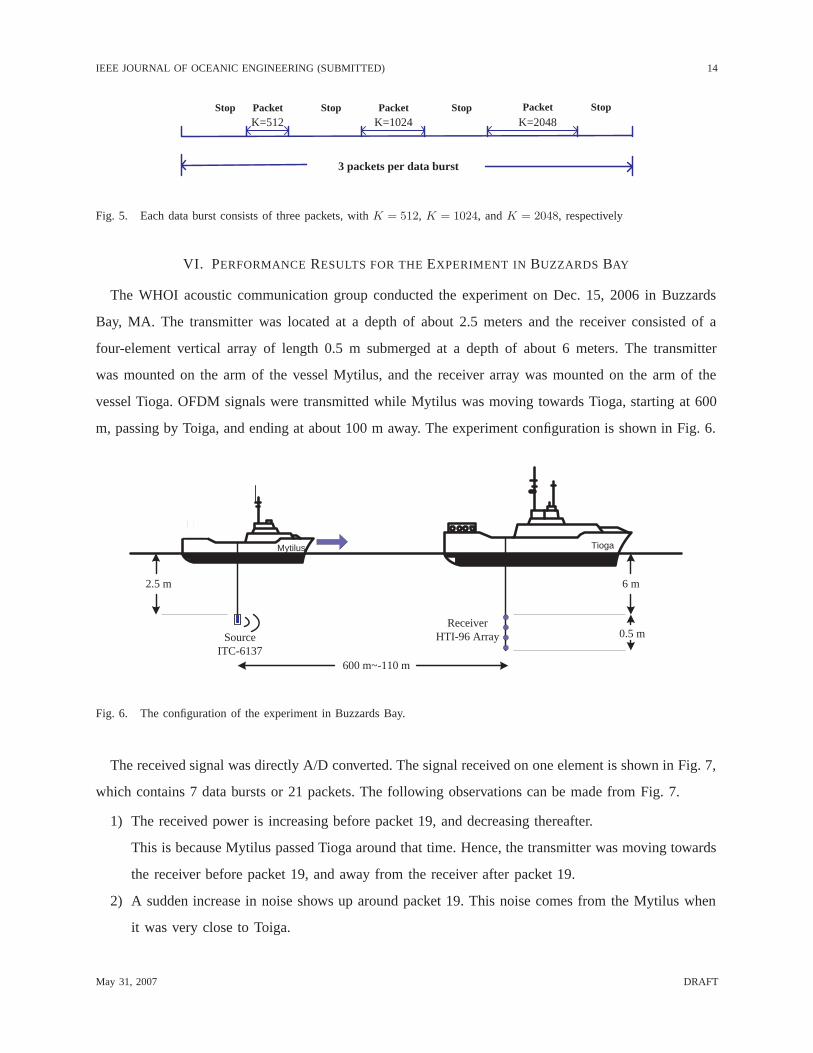
Fig. 5. Each data burst consists of three packets, with K = 512, K = 1024, and K = 2048, respectively
VI. PERFORMANCE RESULTS FOR THE EXPERIMENT IN BUZZARDS BAY
The WHOI acoustic communication group conducted the experiment on Dec. 15, 2006 in Buzzards
Bay, MA. The transmitter was located at a depth of about 2.5 meters and the receiver consisted of a
four-element vertical array of length 0.5 m submerged at a depth of about 6 meters. The transmitter
was mounted on the arm of the vessel Mytilus, and the receiver array was mounted on the arm of the
vessel Tioga. OFDM signals were transmitted while Mytilus was moving towards Tioga, starting at 600
m, passing by Toiga, and ending at about 100 m away. The experiment configuration is shown in Fig. 6.
2.5 m
SourceITC-6137
6 m
0.5 mReceiver
HTI-96 Array
600 m~-110 m
TiogaMytilus
Fig. 6. The configuration of the experiment in Buzzards Bay.
The received signal was directly A/D converted. The signal received on one element is shown in Fig. 7,
which contains 7 data bursts or 21 packets. The following observations can be made from Fig. 7.
1) The received power is increasing before packet 19, and decreasing thereafter.
This is because Mytilus passed Tioga around that time. Hence, the transmitter was moving towards
the receiver before packet 19, and away from the receiver after packet 19.
2) A sudden increase in noise shows up around packet 19. This noise comes from the Mytilus when
it was very close to Toiga.
May 31, 2007 DRAFT

IEEE JOURNAL OF OCEANIC ENGINEERING (SUBMITTED) 15
Fig. 7. Received signal (in voltage) for the Buzzards Bay experiment.
3) The second packet was severely distorted. The reason is unclear.
Simple data processing reveals the following:
4) The signals prior to packet 19 were compressed, which confirms the fact that the transmitter
was moving towards the receiver. The signals after that were dilated, confirming the fact that the
transmitter was moving away from the receiver.
We next present numerical results based on the sequence of the receiver processing outlined in Section
IV. We present a selected set of results and comparisons. A companion technical report contains a more
detailed analysis [31].
A. Doppler scale estimation
For each of the 21 packets transmitted, the algorithm of Section IV-A was used to estimate the Doppler
scale. Based on each Doppler scale a, the relative speed between the transmitter and the receiver was
estimated as v = a · c, using a nominal sound speed of c = 1500 m/s. The resulting Doppler shift at the
carrier frequency, afc, is shown in Table IV, which summarizes the results for element 1.
We see from Table IV that the Doppler shifts are much larger than the OFDM subcarrier spacing. For
example, if v = −8.30 knots (packet 15), which indicates that Mytilus was moving toward Tioga at such
May 31, 2007 DRAFT

IEEE JOURNAL OF OCEANIC ENGINEERING (SUBMITTED) 16
a speed, the Doppler shift is -76.98 Hz at fc = 27 kHz, while the subcarrier spacing is only Δf = 23.44
Hz, 11.72 Hz, and 5.86 Hz for K = 512, 1024, 2048, respectively. Hence, re-scaling the waveform (even
coarsely) is a necessary step to reduce the Doppler effect nonuniformly in the frequency domain.
Table IV also reveals how Mytilus was moving. At first, Mytilus was accelerating towards Tioga.
When it was approaching Tioga, it slowed down but continued to move until it passed Tioga. While
transmitting packets 18 and 19, Mytilus was passing by Tioga, as the speed changed from a negative
value to a positive value.
TABLE IV
COARSE ESTIMATION OF RELATIVE SPEED AND DOPPLER SHIFTS FOR ELEMENT 1.
Packet Doppler shift due to Relative speed (knots) Packet Doppler shift due to Relative speed (knots)
to scaling at fc (Hz) to scaling at fc (Hz)
1 -17.34 -1.86 12 -41.79 -4.50
2 -42.49 -4.58 13 -42.45 -4.58
3 -41.87 -4.52 14 -64.04 -6.91
4 -40.29 -4.35 15 -76.98 -8.30
5 -39.37 -4.25 16 -83.95 -9.04
6 -39.69 -4.27 17 -76.68 -8.26
7 -41.91 -4.52 18 -73.34 -7.90
8 -41.62 -4.48 19 53.96 5.82
9 -40.34 -4.35 20 58.34 6.29
10 -39.68 -4.26 21 57.15 6.17
11 -40.60 -4.38
B. High-resolution residual Doppler estimation
The high-resolution CFO estimation was performed on a block-by-block basis, as detailed in Section
IV-B. Fig. 8 shows the CFO estimates for packets 5 and 17 for K = 1024. We observe that the CFO
changes from block to block roughly continuously but cannot be regarded as constant. The CFO estimate
is on the order of half of the subcarrier spacing. Without the CFO fine tuning, the receiver performance
would deteriorate considerably.
We have also examined joint Doppler scale and CFO fine tuning on each OFDM block based on null
subcarriers, which requires a two-dimensional search for the scale b and the CFO ε. The performance
improvement is marginal in this experiment, so we skip results on the joint approach.
May 31, 2007 DRAFT

IEEE JOURNAL OF OCEANIC ENGINEERING (SUBMITTED) 17
0 5 10 15 20 25 30 35−8
−6
−4
−2
0
2
4
6
OFDM block
CF
O [H
z]
4.25 knots8.26 knots
Fig. 8. The estimated residual Doppler (CFO) for packet 5 (with a relative speed of 4.25 knots) and packet 17 (with a relative
speed of 8.26 knots). The CFO fluctuates rapidly from one block to another.
C. Channel estimation
Channel estimation is based on equi-spaced pilots, as detailed in Section IV-C. We used N p = K/4
data symbols as pilots. Other choices are also possible. Fig. 9 depicts the estimated channel impulse
responses for two cases. In one case Mytilus was moving toward Tioga at a relative speed of 4.25 knots
(packet 5), and in the other case at a relative speed of 8.26 knots (packet 17). The channel duration is
about 4.5 ms. There is a strong direct path between the transmitter and the receiver. The energy in the
8.26 knots case is higher than that in the 4.25 knots case. This observation matches the power profile
shown in Fig. 7.
A second path is also observed in Fig. 9. We conjecture that this path is from the bottom bounce. This
conjecture is well supported by a rough computation based on the channel geometry:
• Case 1: suppose that the distance is 400m, the depth is 12 m, then the delay between the bottom
bounce and the direct path is (2 · √2002 + 122 − 400)/1500 = 0.48 ms.
• Case 2: suppose that the transmitter is now 150m from the receiver, and the depth is 12m. Then the
delay between the bottom bounce and the direct path is (2 · √752 + 122 − 150)/1500 = 1.3 ms.
These numbers roughly correspond to the inter-arrival times marked in Fig. 9. The arrival corresponding
to the second peak can thus be assumed to be from a bottom bounce.
May 31, 2007 DRAFT

IEEE JOURNAL OF OCEANIC ENGINEERING (SUBMITTED) 18
0.42 1.25 2.08 2.92 3.75 4.58
0
0.1
0.2
0.3
0.4
0.5
0.6
0.7
0.8
0.9
τ [ms]
|h(τ
)|
8.26knots
4.25 knots
1
1.3 ms
0.45 ms
Fig. 9. Channel estimates for two example cases. One is for a case with a relative speed of 4.25 knots (packet 5), the other is
for a case with a relative speed of 8.26 knots (packet 17). The channel delay spread is about 4.5 ms. There is a strong direct
path between the transmitter and the receiver. The channel energy in the 8.26 knots case is higher than that in the 4.25 knots
case, as the transmitter is closer. The second peak is conjectured to be from the bottom bounce.
D. Uncoded BER performance, single channel reception
From the large amount of recorded signals we choose to demonstrate a subset of results corresponding
to the K = 512 case with packets 1, 4, 7, 10, 13, 16, 19. The results for the K = 512 case are summarized
in Table V. The BER results for the K = 1024 and K = 2048 cases are similar to those of the K = 512
case. Based on these results, we make the following observations.
1) Without coding, the receiver is able to provide good performance.
2) The number of erroneously detected bits is zero when the speed is low (e.g., packet 1) or when it
is very stable (e.g., packet 16).
3) The receiver is able to handle a speed of up to 9 knots.
4) There are several consecutive “bad” blocks in packets 19 and 20, which lead to large BERs.
The reason for such a behaviour is that the transmitter was moving from a close distance of 600m to
the receiver. While transmitting packets 19 and 20, the transmitter was passing by the receiver. The
Doppler frequencies are thus changing from negative to positive values; i.e., they are not constant.
May 31, 2007 DRAFT

IEEE JOURNAL OF OCEANIC ENGINEERING (SUBMITTED) 19
TABLE V
UNCODED BER FOR K = 512, ELEMENT 4. (I)
Packet 1 4 7 10 13 16 19
Block (-1.86 knots) (-4.35 knots) (-4.52 knots) (-4.26 knots) (-4.58 knots) (-9.04 knots) (5.82 knots)
. . . . . . . . . . . . . . . . . . . . . . . .
21 0 0 0.001 0.001 0.008 0 0.028
22 0 0 0.003 0.004 0.006 0 0.090
23 0 0 0.007 0.001 0 0 0.146
24 0 0 0.004 0 0.007 0 0.612
25 0 0 0.003 0.003 0.007 0 0.639
26 0 0 0.004 0.003 0.004 0 0.647
27 0 0 0.003 0.001 0 0 0.646
28 0 0 0.003 0.003 0.003 0 0.636
29 0 0 0 0.003 0.004 0 0.629
30 0 0 0 0.003 0.003 0 0.636
31 0 0 0.004 0.006 0.001 0 0.625
32 0 0 0.001 0.003 0 0 0.190
33 0 0 0.006 0.001 0.003 0 0.140
34 0 0 0.006 0.004 0.001 0 0.059
35 0 0 0.007 0.003 0.001 0 0.014
· · · · · · · · · · · · · · · · · · · · · · · ·Average over
64 blocks 0 2.2 × 10⁻⁴ 2.5 × 10⁻³ 4.3 × 10⁻³ 1.4 × 10⁻³ 0 9.6 × 10⁻²
Also, the noise level increases during the passing. When the transmitter had passed by the receiver,
which was the case in packet 21, the performance recovered, and the number of errors reduced to
almost zero.
5) A large number of errors are observed in several blocks of packet 2 (with K = 1024). This received
packet was badly distorted (see Fig. 7).
6) A large number of errors also occurred in several blocks of packet 14. The reason for these errors
is not clear.
E. Coded BER performance, single channel reception
All the information bits have been coded by a rate 2/3 convolutional code obtained by puncturing a
rate 1/2 code. The Viterbi algorithm was used for decoding after OFDM demodulation.
As shown in Table VI, the number of bit errors for most blocks is zero. Only a few blocks have large
May 31, 2007 DRAFT

IEEE JOURNAL OF OCEANIC ENGINEERING (SUBMITTED) 20
coded BERs; the blocks coincide with an uncoded BER above a certain threshold. The errors occur in
a few consecutive blocks in packet 19, where the assumption of constant velocity does not hold, as the
Doppler frequency changes from negative to positive. Once the Doppler becomes stable, the performance
recovers. We emphasize that with block-by-block processing, decoding errors in previous blocks have no
impact on future blocks. Hence, the receiver is robust to abrupt phase changes.
TABLE VI
CODED BER FOR K = 512, ELEMENT 4. (I)
Packet 1 4 7 10 13 16 19
Block (-1.86 knots) (-4.35 knots) (-4.52 knots) (-4.26 knots) (-4.58 knots) (-9.04 knots) (5.82 knots)
1, . . . , 21 0 0 0 0 0 0 0
22 0 0 0 0 0 0 0
23 0 0 0 0 0 0 0.0268
24 0 0 0 0 0 0 0.4896
25 0 0 0 0 0 0 0.4834
26 0 0 0 0 0 0 0.5351
27 0 0 0 0 0 0 0.5020
28 0 0 0 0 0 0 0.5103
29 0 0 0 0 0 0 0.4731
30 0 0 0 0 0 0 0.4628
31 0 0 0 0 0 0 0.4731
32 0 0 0 0 0 0 0.2995
33 0 0 0 0 0 0 0.04545
34 0 0 0 0 0 0 0
35, · · · , 64 0 0 0 0 0 0 0
F. BER performance with multi-channel combining
Other than coding, multi-channel combining significantly improves the system performance. To
illustrate this fact, we give two examples, corresponding to K = 1024 and 4-element MRC. The first
example is that of packet 11. The uncoded BER with single channel processing (element 1) is 4.6×10⁻⁴.
Using four elements, the number of bit errors is zero. The second example is that of packet 17. The
single element BER is now 8.8×10⁻⁵. Again, combining four elements eliminates all errors. The scatter
diagrams for single-element reception and MRC combining of packet 17 are shown in Fig. 10.
May 31, 2007 DRAFT

IEEE JOURNAL OF OCEANIC ENGINEERING (SUBMITTED) 21
(a) (b)
Fig. 10. The scatter diagrams for packet 17: (a) single-element reception, and (b) four-element MRC combining.
VII. PERFORMANCE RESULTS FOR THE EXPERIMENT IN WOODS HOLE HARBOR
This experiment was conducted on Dec. 1, 2006. The signal was transmitted from a depth of about
2.5 meters and received by a four-element vertical array with inter-element spacing 0.5 m, submerged
at a depth of about 6 meters. The transmitter was mounted on the arm of the ship Mytilus, and the
receiver array was attached to a buoy close to the dock. OFDM signals were transmitted while Mytilus
was moving away from the dock starting from a distance of 50 m and ending at about 800 m. Then
Mytilus moved towards the dock. The configuration is shown in Fig. 11.
2.5 m 4.6 m
1.5 m Receiver Array
800 m~50 m
Mytilus
dock
buoy
SourceITC-6137
Fig. 11. The configuration for the experiment in Woods Hole harbor.
It was found that the channel condition was very difficult with strong multipath after the guard interval
of 25ms. The last strong path is evident at about 80 ms, as shown in Fig. 12. The approximate channel
profile in Fig. 12 is obtained via correlating the received preamble with the known preamble. This long
May 31, 2007 DRAFT

IEEE JOURNAL OF OCEANIC ENGINEERING (SUBMITTED) 22
Fig. 12. The channel profiles obtained by the linear frequency-modulated (LFM) preamble matching. The channel in the Woods
Hole Harbor experiment has strong returns even after the guard interval of 25ms. As a result, inter-block interference exists.
Unlike this situation, the channel in the Buzzards Bay experiment has delay spread much less than the guard interval.
delay spread is likely due to the reflections off the pilings near the dock.
With the channel delay spread longer than the guard interval, inter-block interference (IBI) emerges.
We have not tried the channel shortening approach to reduce the IBI before OFDM demodulation (e.g.,
using methods from [32]–[34]). Instead, we treated all multipath returns after the guard interval as additive
noise; hence, the system is operating at low signal-to-noise ratio (SNR). Nevertheless, with channel coding
and multichannel reception, satisfactory performance is still achieved, which speaks for the robustness
of the proposed receiver.
We next present numerical results of two data bursts. One data burst was transmitted when Mytilus
was moving away from the dock at a low speed of about 3 knots. The other data burst was transmitted
when Mytilus was moving towards the dock at a high speed of about 10 knots. A companion technical
report for this experiment is available in [35].
May 31, 2007 DRAFT

IEEE JOURNAL OF OCEANIC ENGINEERING (SUBMITTED) 23
TABLE VII
COARSE ESTIMATION OF DOPPLER SHIFT AND RELATIVE SPEED FOR ELEMENT 1.
the 3-knot case the 10-knot case
Packet Doppler shift due to Relative speed Packet Doppler shift due to Relative speed
scaling at fc (Hz) (knots) scaling at fc (Hz) (knots)
1 (K=512) 23.84 2.56 1 (K=512) -91.49 -9.86
2 (K=1024) 21.30 2.29 2 (K=1024) -87.88 -9.47
3 (K=2048) 24.06 2.60 3 (K=2048) -96.03 -10.36
A. Doppler scale estimation
We estimate the Doppler scale for each packet within the two data bursts. Table VII shows that the
estimated speeds reflect the experimental settings, which are approximately at 3 knots and 10 knots.
The Doppler shifts at fc = 27 kHz are very large for both cases. In the 3-knot case (low-speed case),
the Doppler shift is on the order of the OFDM subcarrier spacing (23.44 Hz when K = 512). In the
10-knot case (high-speed case), the Doppler shift is much greater than the subcarrier spacing. Hence,
re-scaling the waveform (even coarsely) is a necessary step to reduce the Doppler effect nonuniformly
in the frequency domain.
B. High-resolution Residual Doppler estimation
Figs. 13, 14, and 15 show the CFO estimates for packets 1, 2 and 3 of element 1, respectively. The
following observations are made:
10 20 30 40 50 60−15
−10
−5
0
5
10
OFDM block
CF
O [H
z]
Packet 1, element 1, low−speed casePacket 1, element 1, high−speed case
Fig. 13. The estimated residual Doppler of packet 1 for the low speed case of 2.56 knots and for the high speed case of 9.86
knots. K = 512 and each packet has 64 OFDM blocks.
May 31, 2007 DRAFT

IEEE JOURNAL OF OCEANIC ENGINEERING (SUBMITTED) 24
5 10 15 20 25 30−15
−10
−5
0
5
10
15
OFDM block
CF
O [H
z]
Packet 2, element 1, low−speed casePacket 2, element 1, high−speed case
Fig. 14. The estimated residual Doppler of packet 2 for the low speed case of 2.29 knots and for the high speed of 9.47 knots.
K = 1024 and each packet has 32 OFDM blocks.
2 4 6 8 10 12 14 16−5
−4
−3
−2
−1
0
1
2
3
4
5
OFDM block
CF
O [H
z]
Packet 3, element 1, low−speed case
Packet 3, element 1, high−speed case
Fig. 15. The estimated residual Doppler of packet 3 for the low speed case of 2.60 knots and for the high speed case of 10.36
knots. K = 2048 and each packet has 16 OFDM blocks.
1) The CFO changes from block to block smoothly, but cannot be regarded as constant.
2) The residual CFO effect cannot be neglected.
3) The CFO estimates are on the order of half of the subcarrier spacings for the low speed case.
4) In the low-speed case, the CFO changes periodically over time. The period is the same for all three
settings. In the high-speed case, this phenomenon is not present. A possible explanation for this
effect is that Mytilus rises and falls due to waves, which is more pronounced at low speed than at
high speed.
May 31, 2007 DRAFT

IEEE JOURNAL OF OCEANIC ENGINEERING (SUBMITTED) 25
Fig. 16. The estimated channel impulse responses (magnitude) for packets 1-3, element 1 in the low speed case. The delays
around 3 ms are very stable
Fig. 17. The estimated channel impulse responses (magnitude) for packets 1-3, element 1 in the high speed case. The delays
around 3 ms are very stable
C. Channel estimation
Figs. 16 and 17 depict the channels estimates for the 3-knot and the 10-knot cases, respectively. We
observe several stable paths whose delays do not depend on the location and the speed of the transmitter.
For example, there is one stable path around 3 ms. This path could be best interpreted as the first reflected
path from the dock. The receiver is about 2 meters from the dock. Hence, the dock-reflected path will
May 31, 2007 DRAFT
IEEE JOURNAL OF OCEANIC ENGINEERING (SUBMITTED) 26
be delayed by 2 · 2/1500 = 2.6 ms relative to the direct path. This is a constant delay, which does not
depend on the distance between the transmitter and the receiver.
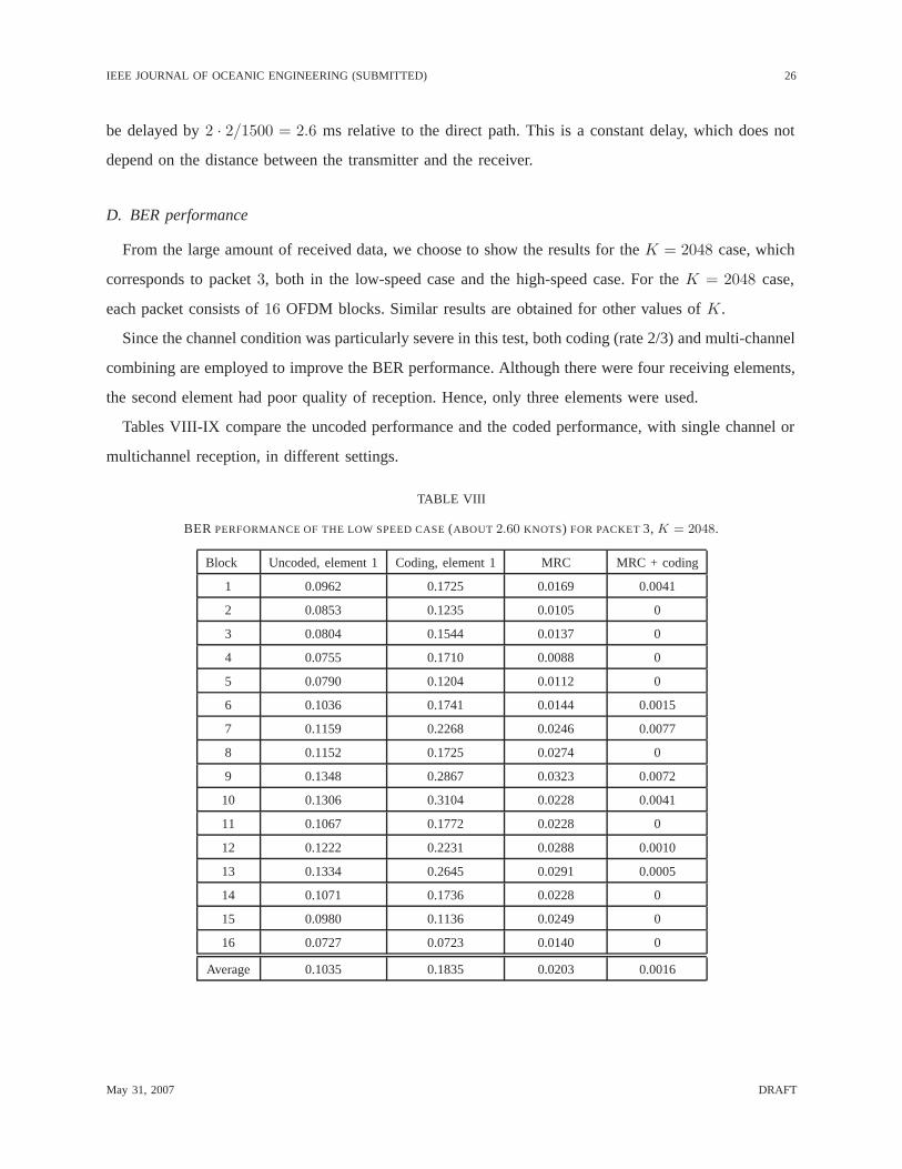
D. BER performance
From the large amount of received data, we choose to show the results for the K = 2048 case, which
corresponds to packet 3, both in the low-speed case and the high-speed case. For the K = 2048 case,
each packet consists of 16 OFDM blocks. Similar results are obtained for other values of K.
Since the channel condition was particularly severe in this test, both coding (rate 2/3) and multi-channel
combining are employed to improve the BER performance. Although there were four receiving elements,
the second element had poor quality of reception. Hence, only three elements were used.
Tables VIII-IX compare the uncoded performance and the coded performance, with single channel or
multichannel reception, in different settings.
TABLE VIII
BER PERFORMANCE OF THE LOW SPEED CASE (ABOUT 2.60 KNOTS) FOR PACKET 3, K = 2048.
Block Uncoded, element 1 Coding, element 1 MRC MRC + coding
1 0.0962 0.1725 0.0169 0.0041
2 0.0853 0.1235 0.0105 0
3 0.0804 0.1544 0.0137 0
4 0.0755 0.1710 0.0088 0
5 0.0790 0.1204 0.0112 0
6 0.1036 0.1741 0.0144 0.0015
7 0.1159 0.2268 0.0246 0.0077
8 0.1152 0.1725 0.0274 0
9 0.1348 0.2867 0.0323 0.0072
10 0.1306 0.3104 0.0228 0.0041
11 0.1067 0.1772 0.0228 0
12 0.1222 0.2231 0.0288 0.0010
13 0.1334 0.2645 0.0291 0.0005
14 0.1071 0.1736 0.0228 0
15 0.0980 0.1136 0.0249 0
16 0.0727 0.0723 0.0140 0
Average 0.1035 0.1835 0.0203 0.0016
May 31, 2007 DRAFT

IEEE JOURNAL OF OCEANIC ENGINEERING (SUBMITTED) 27
TABLE IX
BER PERFORMANCE OF THE HIGH SPEED CASE (ABOUT 10.36 KNOTS) FOR PACKET 3, K = 2048.
Block Uncoded, element 1 Coding, element 1 MRC MRC + coding
1 0.0881 0.1591 0.0172 0.0093
2 0.0913 0.1668 0.0162 0.0015
3 0.0899 0.2340 0.0211 0.0026
4 0.0962 0.1921 0.0274 0.0119
5 0.1148 0.2701 0.0239 0.0145
6 0.1085 0.1932 0.0277 0.0165
7 0.1039 0.2278 0.0197 0.0057
8 0.1085 0.1973 0.0165 0.0207
9 0.1264 0.2939 0.0239 0.0052
10 0.1215 0.2784 0.0204 0.0015
11 0.1152 0.2598 0.0112 0.0036
12 0.1183 0.2242 0.0067 0
13 0.1110 0.2304 0.0133 0
14 0.1152 0.2454 0.0123 0
15 0.1050 0.2009 0.0140 0
16 0.0804 0.1823 0.0119 0
Average 0.1059 0.2222 0.0177 0.0058
Based on Tables VIII and IX for the K = 2048 case, as well as the results for the K = 512, 1024
cases, the following observations are made.
1) The uncoded BER is large, on the order of 10−1 for single-element reception and 10−2 for multi-
channel reception.
2) For single-element reception, coding did not help, in fact worsened the performance, due to the poor
initial condition. However, for multi-channel reception, the BER performance is much improved
when coding is used.
3) These results demonstrate the robustness of the proposed receiver in the presence of a difficult
channel with a delay spread much larger than the OFDM guard interval of 25 ms.
VIII. CONCLUSIONS
In this paper we investigated the application of OFDM in fast-varying underwater acoustic channels.
UWA channels are wideband in nature due to the small ratio of the carrier frequency to the signal
bandwidth; hence, frequency-dependent Doppler drifts destroy the orthogonality among OFDM subcar-
May 31, 2007 DRAFT

IEEE JOURNAL OF OCEANIC ENGINEERING (SUBMITTED) 28
riers. To compensate for the non-uniform Doppler distortion, a two-step approach was used: resampling
followed by high-resolution uniform compensation of the residual Doppler. Null subcarriers facilitate
Doppler compensation, and pilot subcarriers are used for channel estimation. The receiver is based on
block-by-block processing, and, hence, it is suitable for fast-varying underwater acoustic channels.
The method proposed was tested in two shallow water experiments. Excellent performance was achieved
even when the transmitter and the receiver were moving at a relative speed of up to 10 knots, where the
Doppler shifts are greater than the OFDM subcarrier spacing. Experimental results suggest that OFDM
is a strong candidate for high-rate underwater acoustic communications over fast-varying channels.
Future research should address the following topics:
1) investigation of channel shortening approaches (e.g., [32]–[34]) to deal with channels with delay
spread larger than the guard interval.
2) extension of resampling to general time-varying filtering for Doppler shortening in the frequency
domain. Resampling can be approximated by a form of linear time-varying (LTV) filtering operation
(as shown in [27]), which is applicable to channels with similar Doppler rates on all paths. This
operation should be extended to deal with channels with different Doppler rates on different paths.
3) multi-input multi-output (MIMO) OFDM for increased system capacity. MIMO extensions for
single carrier transmission have been recently pursued in [36], [37]; however, no studies have been
reported for multi-carrier modulation in underwater acoustic channels.
REFERENCES
[1] B. Li, S. Zhou, M. Stojanovic, L. Freitag, and P. Willett, “Non-uniform Doppler compensation for zero-padded OFDM
over fast-varying underwater acoustic channels,” in Proc. of MTS/IEEE OCEANS conference, Aberdeen, Scotland, June
18-21, 2007.
[2] M. Stojanovic, “Recent advances in high-speed underwater acoustic communications,” IEEE Journal of Oceanic Engineer-
ing, vol. 121, no. 2, pp. 125–136, Apr. 1996.
[3] D. B. Kilfoyle and A. B. Baggeroer, “The state of the art in underwater acoustic telemetry,” IEEE Journal of Oceanic
Engineering, vol. 25, no. 1, pp. 4–27, Jan. 2000.
[4] D. J. Garrood, “Applications of the MFSK acoustical communication system,” in Proc. of OCEANS, Boston, MA, 1981.
[5] A. Baggeroer, D. E. Koelsch, K. von der Heydt, and J. Catipovic, “DATS — a digital acoustic telemetry system for
underwater communications,” in Proc. of OCEANS, Boston, MA, 1981.
[6] M. Stojanovic, J. A. Catipovic, and J. G. Proakis, “Adaptive multichannel combining and equalization for underwater
acoustic communications,” Journal of the Acoustical Society of America, vol. 94, no. 3, pp. 1621–1631, 1993.
[7] ——, “Phase-coherent digital communications for underwater acoustic channels,” IEEE Journal of Oceanic Engineering,
vol. 19, no. 1, pp. 100–111, Jan. 1994.
May 31, 2007 DRAFT

IEEE JOURNAL OF OCEANIC ENGINEERING (SUBMITTED) 29
[8] A. Doufexi, S. Armour, M. Butler, A. Nix, D. Bull, J. McGeehan, and P. Karlsson, “A comparison of the HIPERLAN/2
and IEEE 802.11a wireless LAN standards,” IEEE Communications Magazine, vol. 40, no. 5, pp. 172–180, May 2002.
[9] IEEE Standard 802.16 Working Group, IEEE standard for local and metropolitan area networks part 16: air interface for
fixed broadband wireless access systems, 2002.
[10] E. Bejjani and J. C. Belfiore, “Multicarrier coherent communications for the underwater acoustic channel,” in Proc. of
OCEANS, 1996.
[11] W. K. Lam and R. F. Ormondroyd, “A coherent COFDM modulation system for a time-varying frequency-selective
underwater acoustic channel,” in Proc. of the 7th International Conference on Electronic Engineering in Oceanography,
June 1997, pp. 198–203.
[12] W. K. Lam, R. F. Ormondroyd, and J. J. Davies, “A frequency domain adaptive coded decision feedback equalizer for a
broadband UWA COFDM system,” in Proc. of OCEANS, 1998.
[13] Y. V. Zakharov and V. P. Kodanev, “Multipath-Doppler diversity of OFDM signals in an underwater acoustic channel,” in
IEEE International Conference on Acoustics, Speech, and Signal Processing, vol. 5, June 2000, pp. 2941–2944.
[14] S. Coatelan and A. Glavieux, “Design and test of a coded OFDM system on the shallow water acoustic channel,” in Proc.
of OCEANS, Sept. 1994.
[15] B. Kim and I. Lu, “Sea trial results of a robust and spectral-efficient OFDM underwater communication system (Abstract),”
The Journal of the Acoustical Society of America, vol. 109, no. 5, pp. 2477–2477, May 1, 2001.
[16] R. Bradbeer, E. Law, and L. F. Yeung, “Using multi-frequency modulation in a modem for the transmission of near-realtime
video in an underwater environment,” in Proc. of IEEE International Conference on Consumer Electronics, June 2003.
[17] P. J. Gendron and T. C. Yang, “Environmental and motion effects on orthogonal frequency division multiplexed on-off
keying,” in American Institute of Physics Conference Series, vol. 728, Nov. 2004, pp. 98–105.
[18] M. Chitre, S. H. Ong, and J. Potter, “Performance of coded OFDM in very shallow water channels and snapping shrimp
noise,” in Proceedings of MTS/IEEE OCEANS, vol. 2, 2005, pp. 996–1001.
[19] P. J. Gendron, “Orthogonal frequency division multiplexing with on-off-keying: Noncoherent performance bounds, receiver
design and experimental results,” Preprint from the author, 2006.
[20] M. Stojanovic, “Low complexity OFDM detector for underwater channels,” in Proc. of MTS/IEEE OCEANS conference,
Boston, MA, Sept. 18-21, 2006.
[21] B. Li, S. Zhou, M. Stojanovic, and L. Freitag, “Pilot-tone based ZP-OFDM demodulation for an underwater acoustic
channel,” in Proc. of MTS/IEEE OCEANS conference, Boston, MA, Sept. 18-21, 2006.
[22] Z. Wang and G. B. Giannakis, “Wireless multicarrier communications: Where Fourier meets Shannon,” IEEE Signal
Processing Magazine, vol. 17, no. 3, pp. 29–48, May 2000.
[23] B. Muquet, Z. Wang, G. B. Giannakis, M. de Courville, and P. Duhamel, “Cyclic prefix or zero-padding for multi-carrier
transmissions?” IEEE Transactions on Communications, vol. 50, no. 12, pp. 2136–2148, Dec. 2002.
[24] R. D. J. van Nee, G. A. Awater, M. Morikura, H. Takanashi, M. A. Webster, and K. W. Halford, “New high-rate wireless
LAN standards,” IEEE Communications Magazine, vol. 37, no. 12, Dec. 1999.
[25] A. Batra, J. Balakishnan, G. R. Aiello, J. R. Foerster, and A. Dabak, “Design of a multiband OFDM system for realistic
UWB channel environments,” IEEE Transactions on Microwave Theory and Techniques, vol. 52, no. 9, pp. 2123–2138,
Sept. 2004.
[26] B. S. Sharif, J. Neasham, O. R. Hinton, and A. E. Adams, “A computationally efficient Doppler compensation system for
underwater acoustic communications,” IEEE Journal of Oceanic Engineering, vol. 25, no. 1, pp. 52–61, Jan. 2000.
May 31, 2007 DRAFT

IEEE JOURNAL OF OCEANIC ENGINEERING (SUBMITTED) 30
[27] L. Freitag, M. Johnson, and M. Stojanovic, “Integrated Doppler tracking and efficient resampling for phase coherent
underwater acoustic receivers,” (Internet draft).
[28] U. Tureli and H. Liu, “A high-efficiency carrier estimator for OFDM communications,” IEEE Communications Letters,
vol. 2, no. 4, pp. 104–106, Apr. 1998.
[29] X. Ma, C. Tepedelenlioglu, G. B. Giannakis, and S. Barbarossa, “Non-data-aided carrier offset estimations for OFDM
with null subcarriers: Identifiability, algorithms, and performance,” IEEE Journal on Selected Areas in Communications,
vol. 19, no. 12, pp. 2504–2515, Dec. 2001.
[30] J. Rinne and M. Renfors, “Pilot spacing in orthogonal frequency division multiplexing systems on practical channels,”
IEEE Transactions on Consumer Electronics, vol. 42, no. 4, Nov. 1996.
[31] B. Li, S. Zhou, and L. Freitag, Performance Results for the Underwater OFDM Experiment at Mudhole, Buzzards Bay, Dec.
15, 2006. Technical Report, UCONN-WCRL-TR-2007-01. downloadable at http://www.engr.uconn.edu/˜shengli/UCONN-
WCRL-TR-2007-01.pdf.
[32] R. K. Martin and C. R. Johnson, Jr., “Adaptive equalization: transitioning from single-carrier to multicarrier systems,”
IEEE Signal Processing Magazine, vol. 22, no. 6, pp. 108–122, Nov. 2005.
[33] J. Kleider and X. Ma, “Adaptive channel shortening equalization for coherent OFDM doubly selective channels,” in Proc.
of International Conference on Acoustics, Speech, and Signal Processing, Toulouse, France, May 15-19, 2006.
[34] X. Ma, R. J. Baxley, J. Kleider, and G. T. Zhou, “Superimposed training for channel shortening equalization in OFDM,”
in Proc. of Milcom, Oct. 2006.
[35] B. Li, S. Zhou, and L. Freitag, Performance Results for the Underwater OFDM Experiment at Woods Hole Harbor, Dec.
01, 2006. Technical Report, UCONN-WCRL-TR-2007-02. downloadable at http://www.engr.uconn.edu/˜shengli/UCONN-
WCRL-TR-2007-02.pdf.
[36] D. B. Kilfoyle, J. C. Preisig, and A. B. Baggeroer, “Spatial modulation experiments in the underwater acoustic channel,”
IEEE Journal of Oceanic Engineering, vol. 30, no. 2, pp. 406–415, Apr. 2005.
[37] S. Roy, T. M. Duman, V. McDonald, and J. G. Proakis, “High rate communication for underwater acoustic channels
using multiple transmitters and space-time coding: Receiver structures and experimental results,” IEEE Journal of Oceanic
Engineering, Feb. 2007.
May 31, 2007 DRAFT