Embed Size (px)
Citation preview
COMPARISON OF SEISMIC PROVISIONS OF EBCS 8 AND CURRENT MAJOR BUILDING CODES PERTINENT TO THE EQUIVALENT STATIC FORCE
ANALYSIS
Asrat Worku Department of Civil Engineering
Addis Ababa University
ABSTRACT
A comparison of seismic ptovisions having relevance to the Equivalent Static Force (ESF) method of analysis according to current major building codys worldwide is presen!ed. The codes compared include the latest two editions of the Uniform Building Code (UBC 94 and UBC 97), the International Building Code (IBC 2000), the European Prestandard (Eurocode 8, 1998), and the Ethiopian Building Code Standard (EBCS 8, 1995). The comparison is mady on the basis of the specified base shear coefficient, the vertical distribution of the base shear, the story shear and overturning moment, the considerations for torsion, P-delta effect, and the limitations on the story drift. Substantial differences are observed among the codes and even within different editions. of~ code, a good example being the UBC series. It is also shown that the most recent American codes like USC 97 and IBC 2000 exhibited drastic changes in the definition of the base shear coefficient and in other pertinent regulations as compared to the classical forms familiar to most users.
INTRODUCTION
The two most cormnon methods of analysis of structures subjected to lateral forces due to seismic action · are the equivalent static force and the response spectrum analyses. The response spectrum analysis is a technique directly based ori structural dynamics theory. It presupposes a structure modeled by a multi-degree-of-freedom (MDOF) oscillator subjected to an earthquake ground motion represented by a desig"Ti response spectrum. Its natural periods and modes of vibration characterize the dynamic behavior of the model. This method of structural analysis demands thus knowledge of vibration of structures and earthquake engineering.
In contrast, the equivalent ~tatic force analysis (ESF) is a highly simplified technique derived froin structural dynamics theory with the aim of
rendering it usable to structural engineers without a sufficient background of vibration theory and earthquake engineering. Its applicability is limited to structures satisfying certain conditions of regularity and height limits. The method is based on the dynamics of a single-degree-of-freedom (SDOF) oscillator or an MDOF system vibrating in
· accordance with a single specified shape. The latter . fype of oscillator is referred also to as a generalized-single-degree-of-freedom system. The dynamic behavior of such models is characterized by a single natural period. The seismic action can be represented by the same design spectrum also employed in the method . of response spectrum analysis described above.
From observations of the analytical relationships developed in the dynamics of generalized SDOF systems, it is possible to establish siniple formulas for the natural period, the seismic action and the manner of height-wise distribution of the lateral force. Various other additional factors like site soil, occupancy importance, inelastic ductile response, and the like, which influence the response can also be taken into account by introducing appropriate coefficients into these formulas. However, different degrees of approximations are associated with the specifications of these quantities depending on past performance of structures to earthquake ground motions, local construction practice and the nature of the ground motions. As a result, provisions of various local codes geared to this effect differ from each other and sometimes substantially.
The objective of this paper is to make a comparison of provisions of selecled codes having relevance to the ESF .'method. Various aspects of the ESF method of analysis are used as bases for comparison. These include the form and details of the .base shear equation; the distribution of the base shear with height; story shear, moment and torsion; secondary effects due to P-delta; and similar others. Suc;:h a comparison is necessary to establish the status ·of codes with respect to others in comm<111 use. It also helps to view codes from the
Journal of EAEA, Vol. 18, 2001
12 Asrat Worku
perspective of the state-of-the-art. For these reasons, such works can not be considered as a one-time job.
A total of five different codes are compared: the last two editions of the Unifom1 Building Code [ 1,3 ]"; the most recent 2000 International Building Code [4]; the Eurocode Prestandard - Eurocode 8, 1998 [6]; and the Ethiopian Building Code Standard [7]. The comparison made on the basis of the criteria mentioned above revealed as expected that no code is fully identical to any other. Some provisions of a code are shared by others, and other provisions are unique to that code. The observations made in the provisions of EBCS 8 are also no exceptions.
A similar work that compares provisions pertinent to the response spectrum method of analysis is p1anned for the near future. It is hoped that such works will play a role to initiate updating of provisions of local codes, particularly EBCS 8.
THE UNIF-ORM BUILDING CODE (UBC) SERIES -
The UBC seismic regulations are generally based on the series of publication of the Structural Engineers Ass6ciation of California (SEAOC) released regularly since 1959, commonly known as the SEAOC Blue Book.
With respect to provisions pertinent to the equivalent static force analysis (ESF), particularly with regard to the basic form of the base shear formula, drastic changes were introduced in UBC 88 and UBC 97. In UBC 88, the formula C, = ZIC/ R,. for the base shear coefficient
replaced the older version of C, = Z I KC S .
Recently, UBC 97 introduced once again a new approach including a significant change in the expression for the base shear coefficient that took the form of c, = c , I/ R T . The details of the last
two forms and other pertinent provisions and requirements will be discussed in the following
• The outdated UBC 94 is included for two reasons: (a) .because the ne'Y fonns of the base shear formula specified
by UBC 97 and IBC 2000 are not expected to be familiar to most potential readers and explanation of them is easier if reference is made to such older and familiar versions; and
(b) because important similarities exist between provisions of EBCS 8 and this code.
Journal of EAEA, Vol.18, 2001
sections on the basis of the 1994 and 1997 releases of the UBC.
UBC94
The UBC 94 seismic regulations are based on the 1990 SEAOC Blue Book - Recommended Lateral Force Requirements and Tentative Commentary -which in tum was partly based on the provisions of the Applied Technology Council recommendations (ATC-06-1978) and of the Building Seismic Safety Council guidelines (BSSC-1994) [ 1,9).
UBC 94 allows the use of the ESF method to all regular structures not taller than 73m and to all irregular structures not exceeding 5 stories or 20m in height irrespective of the seismic zone. Based on the seismic zoning described below, it also allows the ESF method for all structures in Zone l and all common-occupancy structures in Zone 2.
Base Shear
The total base shear is specified as
V = (ZIC/R.,)W (I)
Where Z is the seismic zone factor, I the importance factor, C the site coefficient, Rw the structural system coefficient, and W is the total seismic weight of the structure.
The Seismic Zone Factor, Z
This factor represents the seismicity zone of the site in the USA and assumes one of the values of 0.075, 0.15, 0.20, 0.30, or 0.40.
The Importance Factor, I
This factor is introduced to increase the base shear for essential and hazardous facilities by assigning the maximum value of /= 1.25 while all other structures are assigned /=L.O. It · is worth mentioning that the maximum value of I was 1.50 according to previous versions of the Code like UBC 85 [2].
The Site Coefficient, C
This coefficient is specified by
C = l.25S/T 2 13 ~ 2.7_5 (2)
Comparison of Seismic Provisions 13
where S is the site coefficient and T is the fundamental period of the structure. The ratio Cl Rw is limited to a minimum value of 0.075, which has the effect of setting a minimum value of base shear force for long-period st11,1ctures.
The Building Period, T
The Code specifies two methods for the computation of the period, T.
Method A: This meth.od is based on the empirical formula of
T =Ch 314 I n (3)
in which h. is the height in meters to the top-most floor from the base and C, assumes one of the values of 0.085, 0.073 or 0.049 for steel moment frames, reinforced concrete frames and eccentrically braced frames, or other structures, respectively.
Method B: As an alternative, the Code provides Rayleigh's formula given by:
(4)
where Ji represents a reasonable force distribution consistent with the vertical distribution of the base shear yet to be determined; bi are the elastic lateral deflections due to Ji.
The empirical formulas given in the previous versions of UBC, like UBC 85, based on the
number of stories of .the building and its dimensions are no more provided even as alternatives in this edition. Besides this, Rayleigh's closed form relation, Eq. (4), is provided that has a good theoretical background in structura.1 dynamics.
The Site Coefficient, S
With the purpose of accounting for site soil amplification of the ground motion this coefficient assumes one of the values of 1.0, 1.2, 1.5 or 2.0 depending on the four site 'soil classes provided on the basis of qualitative categorization. This coefficient is no longer specified based on the · period ratio of the structure to the soil, as was the case in, for example, UBC 85.
Structural System Coefficient, Rw
This factor serves the purpose of accounting for structural ductility, and its values range between 4 and 12 depending on the given detailed description of different possible structural systems.
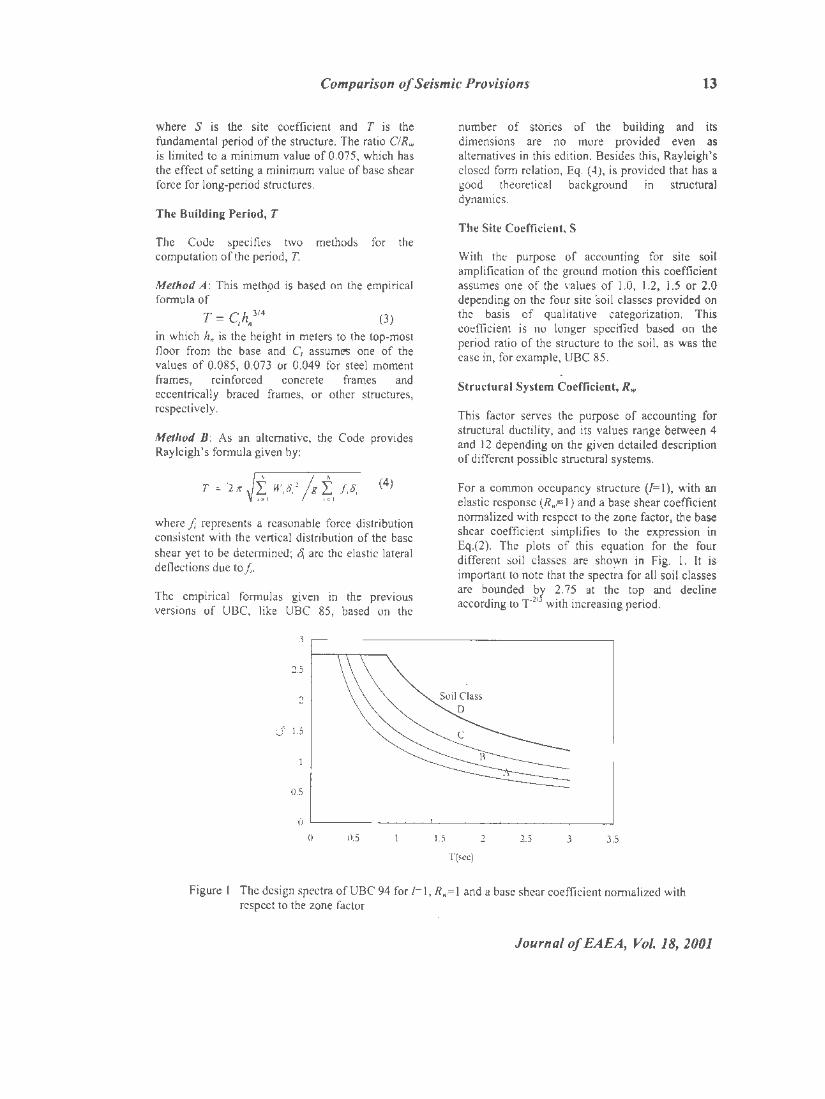
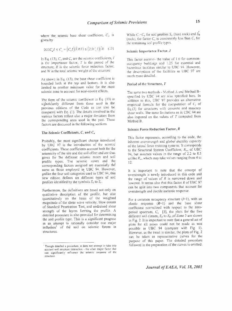
For a common occupancy structure (/=l), with an elastic response (R,.= I) and a base shear coefficient normalized with respect to the zone factor, the base shear coefficient simplifies to the expression in Eq.(2). The plots of this equation for the four different soil classes are sho~n in Fig. 1. It is important to note that the spectra for all soil classes are bounded bl 2. 75 at the top and decline according to r-21 with increasing period.
0 r-~~ ....... ~---;~~..L...t~~-+-"-''--'-~~~"-+"'--'~"-l
0 0.5 f.5 2 2.5 3 3.5
T(sec)
Figure I The design spectra ofUBC 94 for /= I, Rw=I and a base shear coefficient normalized with respect to the zone factor
Journal of EAEA, Vol.18, 2001
14 Asrat Worku
Vertical Distribution of Base Shear
The base shear determined in Eq. (I) is distributed vertically in accordance with:
where the top force, F,, is given by
T ~ 0.7sec:
T> 0.7sec:
F ':o I
F; = 0.07 TV ~ 0.25V (6)
W and h are the weight at and the height from the base to a particuiar floor level.
Story Shear and Story Overturning Moment
The shear force, Vx, and the ·overturning moment, Mx, at any particular story are found as the sum of all lateral forces above and their moment about that story, respectively. Thus
N
v, = F, + L F, (7) ;. x
and N (8)
M' = F,(h. - h,)+ I F,(h,- h,) I• x
Torsion
Where diaphragms are not flexible, the Code requires considering an accidental torsion equal to the story shear times ±5% of the floor plan dimension in the perpendicular direction. This is in addition to the calculated torsion due to the eccentricity between the mass and stiffness centers of the story.
If torsional irregularity exists, the accidental torsion is increased by the factor
in which
Omax = Oavg =
(9)
maximum displacement at Level x; the average displacement at the extreme points of the structure at U:vel x.
Journal of EAEA, Vol. 18, 2001
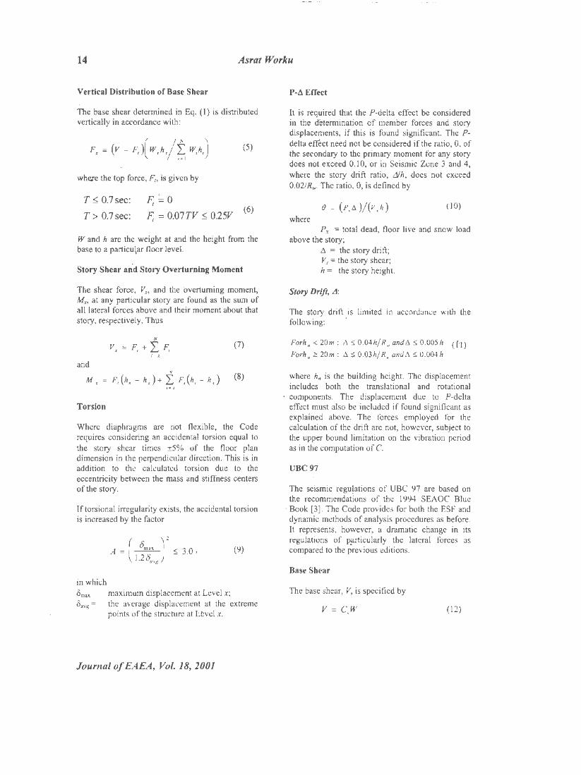
P-d Effect
It is required that the P-delta effect be considered in the determination of member forces and story displacements, if this is found significant. The Pdelta eff'ect need not be considered if the ratio, 9, of the secondary to the primary moment for any story does not exceed 0.10, or in Sei'smic Zone 3 and 4, where the story drift ratio, dh, does not exceed 0.02/Rw. The ratio, 9, is defined by
(IO)
where Px = total dead, floor live and snow load
above th~ story; /:J. = the story drift; Vx = the story shear; h = the story height.
Story Drift, A:
The story drift is limited in accordance with the following: ·
Forh. < 20m: 6. $ 0.04h/R., and6. $ 0.005h (f'l)
Forh. 2!: 20m : 6. $ 0.03h/ R .. and 6. $ 0.004 h
where hn is the building height. The displacement includes both the translational and rotational
· components. The displacement due to P-delta effect must also be included if found significant as explained above. The forces ~mployed for the calculation of the drift are not, however, subject to the upper bound limitation on the vibration period as in the computation of C.
UBC97
The. seismic regu!ations of UBC 97 are based on the recommendations of the I 994 SEAOC Blue
· Book (3]. The Code provides for both the ESF and dynamic methods of analysis procedures as before. It represents, however, a dramatic change in its regulations of P!ITTicularly the lateral forces as compared to the previous editions.
Base Shear
The base shear; V, is specified by
V = C,W (12)
Comparison of Seismic Provisions 15
where tht< seismic base shear coefficient, Cs, is given by
0.1 IC.J :5 c, = (cJ)/(RT) :5 (2sc.1)/R ( 13)
In Eq. (13), c. and C. are the seismic coefficients; I is the importance factor; T is the period of the structure; R is the seismic force reduction factor; and W is the total seismic weight of the structure.
As shown in Eq. ( 13), the base shear coefficient is bounded both at the top and bottom. It is also limited to another minimum value for the most seismic zone to account for near-soutce effects.
The form of the seismic coefficient in Eq. (13) is significantly different from those used in the previous editions of the Code as can also be compared with Eq. (1). The details involved in the various factors reflect also a major deviation from the corresponding ones used in the past. These factors are discussed in the following sections.
The Seismic Coefficients, c. and C"
Probably, the mosr significant change introduced by UBC 97 is the introduction of the seismic coefficients. These coefficients account both for the
' seismicity of the site and the soil effect and are thus given for the different seismic zones and soil profile types. The seismic zones and the corresponding factors assigned are essentially thd same as those employed in UBC 94. However, \lnlike the four soil categoric~ used in UBC 94, thi.s new edition defines six different types of soil profiles identified by the symbols SA to SF.
Furthermore, the definitions are based not only on qualitative description of the profile, but also quantitatively on the basis of the weighted magnitude of the shear wave velocity, blow counts of Standard Penetration Test, and undrained shear strength of the layers forming the profile. A detailed procedure is also provided for determining
. the soil profile type. This is a significant progress in an attempt to rationally consider · one major influence1 of the soil on seismic forces in structures.
1 Though detailed a prcx:edure, it docs not attempt to take into account soil structure interaction • the other major factor that can significantly influence the seismic response of the strocture.
While c.=c. for soil profiles SA (hard rock) and Sa (rock), the factor C0 is consistently less than C, for the remaining soil profile types.
Seismic Importance Factor, I
This factor assumes the value of 1.0 for commonoccupancy buildings and l.25 for essential and hazardous facilities similar to UBC 94. However, the descriptions of the facilities in UBC 97 are much more detailed.
Period of the Structure, T
The same two methods · Method A and Method Bspecified by UBC 94 are also specified here. In addition to this, UBC 97 provides an alternative empirical formula for the computation of C, of Eq.(3) for s.tructures with concrete and masonry shear walls. The same limitations as in UBC 94 are also imposed on the values of T computed from MethodB.
Seismic Force Reduction. Factor, R
This factor represents, according to the code, the inherent overstrength and global ductility capacity of the lateral force resisting systems. It corresponds to the Structural System Coefficient, Rw, of UBC 94, but assumes values in the range of 2.2 to 8.5 unlike R.,, which may take values ranging from 4 to 12.
It is important to note that the concept ~f 'Overstrength is newly introduced in this code and the range of values of R is narrowed down and lowered. It seems also that this factor R of UBC 97 can be split into two components that account for overstrength and ductile inelastic response.
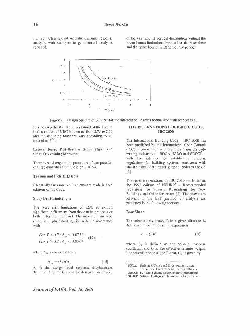
For a common occupancy strucnire (/=!), with an .elastic response (R= I) and the base shear coefficient normalized with respect to the teroperiod spectrum, C0 [3], the plots for the five different soil classes, SA to SE. .pf Zone 3 are shown in Fig. 2. It is important to note that a general set of plots for all zones could not be made as was possible in UBC 94 (compare with Fig. 1). Ho,wever, as the trend is similar, the plots of Fig. 2 can be taken as representative curves for the purpose of this paper. The detailed procedure followed in the preparation of the curves is omitted.
Journal of EAEA, Vol 18, 2001
16 Asrat Worku
For Soil Class SF, site-specific dynamic response analysis with site-s;· :!cific geotechnical study is required.
of Eq. ( 12) and its vertical distribution without the lower bound limitations imposed on the base shear and the upper bound limitation on the period.
Figure 2 Design Spectra ofUBC 97 for the different soil classes normalized with respect to C0
It is not.~worthy that the upper bo'und of the spectra in this edition ofUBC is lowered from 2.75 to 2.50 and the declining branches vary according to T' instead of T 213
•
Lateral Force Distribution, Story Shear and Story Overtuning Moments
There is no change in the procedure of computation of these quantities from those ofUBC 94.
Torsion and P-delta Effects
Essentially the same requirements are made in both editions of the Code.
Story Drift Limitations
The story drift limitations of UBC 97 exhibit significant differences from those in its predecessor both in form and content. The maximum inelastic response displacement, 6m, is limited in accordance with
For T < 0.7: !im S 0.025h; (14)
For.T. ~ 0.7: flm < 0.020h.
where 6m is computed from
(15)
6 1 is the design level response displacement determined on the basis of the design seismic force
Journal of EAEA, Vol. 18, 2001
THE INTERNATIONAL BUILDING CODE, IBC2000
The International Building Code - IBC 2000 has been published by the International Code Council (ICC) in cooperation with the three major US code writing authorities - BOCA, ICRO and SBCCi2 -with the intention of establishing uniform regulations for building systems consistent with and inclusive of the existing model codes in the US [4].
The seismic regulations of IBC 2000 are based on the 1997 edition of NEHRP3
- Reet>mmended Prov!sions for Seismic Regulations for New Buildings and Other Structures (5]. The provisions relevant to the ESF method of analysis are presented in the following sections. .
Base Shear
The seismic base shear, V, in a given direction is determined from the familiar expression
v = c,w (16)
where C, is defined as the seismic response coefficient and W as the effective seisl'llic weight. The seismic response coefficient, C,, is given by
'2 BOCA: Building OUicials and Code Administrators ICBO: International Conference of Building Officials SBCCI: So.11'1em Building Code Congress International
> NEHRP: National Earthquake Hazard Reduction Program
Comparison of Seismic Provisions 17
(17)
It is bounded both at the top and bottom according to the following:
In~· (17) and (18),
Svs=
SDI=
le = T R =
the design spectral response acceleration at short period; the design spectral response acceleration at . one-second period;, the seismic occupancy importance factor; the fundamental period of the building; and the response modification factor ..
The total base shear, V, is also limited to another minimum value for buildings of specified categories. The various factors in Eq. ( 17) and ( 18) are discussed in the following sections.
The Design Spectral Acceleration Parameters, SDsandSDI
The 5%-damped design spectral response acceleration at short periods, S05, and at onesecond period, S0 ., are spe~ified as
(19)
where SMs and SMi are defined as the maximum considered earthquake spectral response accelerations for short period and one-second period, respectively. These quantities are in tui;n given by
(20)
The quantities in Eq. (20) are
F0 and F.: site coefficients; S, and S1: the 5% damped maximum considered
earthquake mapped spec~ral accelerations for short period and one-second period structures on Site Clas,s-·B.
The site Coefficients, F. and F,
The subscripts a and v on the site coefficients, F0
and F.,, seem!ngly indicate the free ground acceleration and velocity that are amplified most by the structure in the short and long period ranges, respectively. Values of F0 and Fv are provided in a tabular form as functions of the Site Class and the 5%-damped mapped spectral respo~se accelerations, S, and S1•
The latter are provided in form of contoured maps for the whole of the US to a significant detail. It is thus important to note that this marks a milestone in the definition bf the base shear coefficient for ESF method of analysis: from the classical peak ground acceleration-based definition to this new acceleration response spectrum-based definition.
Six different site classes ranging from Site Class A to F are defined. For Site Class A (hard rock) and Site Class B (rock) both site coefficients are equal assuming the value of l.O and 0.80, respectively, irrespective of the mapped spectra, Ss and S1• The values of F0 and F. consistently increase starting from the above values with the site class tending from B (rock) to E (soft soil profile) for a specified S, or S1• These quantities decrease, . however, consistently with increasing values of Ss or S1 for a given site class between C and E. No specific values of F0 and Fv are assigned to Site Class F for all values of S, and S1• Rather, site-specific geotechnical investigation and dynamic site response an!ilyses are required for this site class.
A detailed procedure similar to that given by UBC 97 is also provided by IBC 2000 for site classification on tlie basis of shear wave velocity, standard penetration test blow·count, and undrained shear strength of the layers forming the soil profile of a site.
The Seismic Occupancy Importance Factor, le
This factor assumes one of the values of 1.0, 1.25 or l.50 depending on the occupancy nature. The maximum value of 1.50 is an evident deviation from the UBC 97 requirements, in which this large value was dropped.
The Fundamental Period, T
IBC 2000 requires that T be established with the help of a properly substantiated analysis using the
Journal of EAEA, Vol 18, 2001
18 Asrat Worku
structural properties and deformational characteristics of the resisting elements. As an alternative, it also provides the approximate formula ofEq. (3) given by both UBC 94 and UBC 97.
The Code provides also an additional formula for concrete and steel-moment resisting frame buildings not exceeding 1.2 stories in height and with a minimum story height of 3m. This latter formula is given by
~ = O.lN (21)
where N is the number of stories atid T0 is the approximate period. It is to be noted that this formula was provided by earlier editions of UBC, for example UBC 85, as an alternative, but for all
. building types.
The Code requires that the period, T, calculated on the basis of properly substantiated analysis methods be limited in accordance with
(22)
where Cu is referred to as the coefficient for upper limit on calculated period and provided by the Code as a function of SD•· The values of Cu
increase from t.i to 1.7 with decreasing values of SDJ. This requirement deviates once again from that ofUBC97.
The Response Modification li'actor, R
This factor varies from 1.25 for inverted pendulum structures with ordinary steel moment frames to 8
. for some moment resisting frames and dual systems. The details in the description . of the different structural systems and the allocation of values of R are more exhaustive in this code than in any of the UBC series.
It can be shown that R can be expressed as the product of two factors: a ductility reduction factor, R.,, and a structural overstrength factor~ .Qi. This trend Gf splitting the response modification factor into Rd and .Qi is inherent in the code but not explicitly stated. It seems that the approach ofUBC 97 that provides only global values of the factor, R, instead of separate values of Rd and .Qi, is preferred
. until seemingly further research shades better light on the issue.
Journal of EAEA,.Vol. 18, 2001
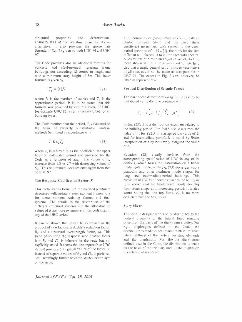
For a common occupancy structure {lt=l), with an elastic response (R= I) and the base shear coefficient normalized with respect to the zeroperiod spectrum of 0.4S0 s [ 4), the plots for the five different soil classes, A to E, for sites with spectral accelerations of S1=0.3 and Ss=0.75 are identical to those shown in Fig. 2. It is important to note here also that a single general set of plots representative of all sites could not be made as was possible in UBC 94. The curves in Fig. 2 can, however, be taken as representative.
Ve'rtical Distribution of Seismic Forces
The base shear determined using Eq. (16) is to b~ distributed vertically in accordance with
F, = v( W,h,k/~ W,h/) (23)
In Eq. (23), k is a distribution exponent related to the building period. For T:'>0.5 sec, k assumes the value of 1, for ~2.5 it is assigned the value of 2, and for intermediate periods k is found by linear interpolation or may be simply assigned the value of2.
Equation (23) clearly deviates from the corresponding specification of UBC in any of its editions, which bases the distribution on a linear fundamental mode, while Eq. (23) envisages also a parabolic and other nonlinear mode shapes for long- and intermediate-period buildings. This provision of lBC is of co.urse closer to the reality as it is !mown that the fundamental mode deviates· from linear shape with increasing period. It is also worth noting that the top force, Fl> is no more deducted from the base shear.
Story Shear
The seismic design shear is to be distributed to the vertical elements of the lateral force resisting system on the basis of the diaphragm rigidity. For rigid diaphragms defined in the Code, the distribution is made in accordaiice with the relative lateral stiffness of the vertical resisting elements and the diaphragm. For flexible diaphragms defined also in the Code, the distribution is made on tbe basis of the tributary area of the diaphragm to each line of resistance.
Comparison of Seismic Provisions 19
Story Overturning Moment
The overturning mome11t, Mx. at any level, x, is determined from
N
M, =TL F,(h,- h,} (24) ,. '
The various terms in Eq. (24) are a~ defined earlier, except the overturning morttent reduction factor, r. This factor assumes the value of 1.0 for the top 10 stories, 0.8 for the 20•h story from the top and below, and an intermediate value obtained by linear interpolation for the stories between the I 01h and 201
h story from the top. •
This concept of reducing the story overturning moment for lower stories of high-rise buildings is once again a new approach presumably introduced to account for the flexibility of the structure that can exhibit reversal of force direction. It is implied that the reduction is not made for I 0-story and shorter buildings.
Torsion
Where diaphragms are not flexible, the sum of the actual torsion, M,, and the accidental torsion, Ma,, is considered in the distribution of the story shear. The accidental torsion is based on the ±5% eccentricity specified also by UBC.
For structures exhibiting torsional irregularities, the effects are accounted for by multiplying the sum of M, and Ma, by the same factor given in Eq. (9), unlike in UBC 94 and 97, where this factor is applied only on the accidental torsion, M01• The deviation from the corresponding UBC requirement is once again evident.
Story Drift Determi,nation and Limitations
The design story drift, LI, is generally computed as the difference of the deflections at the center of mass at the top and bottom of the story under consideration.
The deflection, 8,,, of Level, x, is determined from
(25)
where
o,.= the deflection determined from the elastic structural analysis without the upper bound limitations of Eq. (22) imposed on the penod, T.
Cd= the deflection amp Ii ti cation factor ranging from 1.25 to 6.5 provided in the same manner as response modification factor, Rw.
h = is the occupancy importance factor.
The design story drift is limited to the allowable story drift, 4,, for any story, which is provided as a fraction of the story height, hu, based on the building type and seismic use group. Accordingly, 4, ranges from 0.007hs:c to 0.025hw For common reinforced concrete and s.teel structures taller than four stories, 4, takes one of 0.01 Ohm 0.0 l 5hsx or 0.020'1.... depending on the seismic group. For masonry shear wall and masonry wall-frame buildings, 4, takes generally smaller values.
Consideration of P-delta Effects
The significance of the P-delta is measured by the stability coefficient, (), defined in a slightly modified form than Eq. (JO) as
(26)
where P, is defined as the total unfactored vertical design load at and above Level x; Vx is the story shear force; and the remaining terms are as defined earlier. The secondary effects of the P-delta need not be considered if B does not exceed 0.10 as is also allowed by UBC 94 and 97.
The stability coefficient is also bounded on the top by
Bm,. = 1/(2pc;) S 0.25 (27)
in which P is the ratio of the shear demand to the shear capacity for the story. A value of 1.0 is allowed if this ratio is not calculated. Eq. (27) is once again a new addition by IBC 2000 towards considering the effects of P-delta.
If the computed value of () is between 0.10 and Bma., the ?-delta effect is included in the determination of the interstory drifts and element forces. In order to account for the P-delta effect on the story drift, for example,. the design story drift is
increased by the factor ad = l/( I - B). If e is greater than Bmax. the structure is potentially
Journal of EAEA, Vol. 18, 2001
20 Asrat Worku
unstable and needs redesigning. This latter important precautionary note is not explicitly stated in any version of the UBC series.
THE EUROPEAN PREST ANDARD, EUROCODE 8 -1998
The European Committee for Standardization published this and other pertinent documents in 1994. Eµrocode 8 deals with the design and construction of buildings and other works in seismic regions of Europe [6].
This volume stipulates two basic types of analysis, the choice of which depend~ on the structural characteristics of the building to be analyzed. Of these, the Simplified, Modal Response Spectrum Analysis can be interpreted as the Equivalent Static Force (ESF) methoq. It is supposed to· be applied to buildings that can be analyzed by two planar models and whose response is not significantly affected by contributions of higher modes. The important features of this method are briefly presented below in comparison with pertinent regulations of the UBC and IBC discussed earlier.
Base Shear
The s.eismic base shear is given by the equation
(28)
In Eq. (28), Sj._T1) is the ordinate of the design spectrum at the fundamental period, Ti, given by the following equation for the important period range:
(29)
In Equation (29), a is the design ground acceleration ratio; S is the soil parameter; /Jo is the spectral acceleration amplification factor for 5% damping; q is the behavior factor; Ts and Tc are limits of the constant acceleration branch llnd To is
·the beginning of the constant displacement branch of the design spectrum. The values of these
Journal of EAEA, Vol. 18, 2001
parameters are provided for 50% probability of exceedance of the spectral ordinates over the whole period range.
It is to be observed that all branches of the design spectrum are· dependent on the soil parameter, S. This is in contrast to the design spectra of many other codes, where the spectra are all limited to a single constant value in the constant acceleration region (Compare Figure 3 with Figures 1 and 2).
The Design G round Acceler ation Ratio, a
This is the ratio of the design ground acceleration, a8 , to the gravitational acceleration,g. The Code envisages that the National Authorities of Europe would be subdivided into seismic zones depending on the local hazard. The hazard within each zone is assumed to be constant and described by the single parameter, a8 , in rock or firm soil. This design ground acceleration corresponds to a reference return period of 475 years and, to which is assigned an importance factor qf one.
The Soil Parameter, S
The soil parameter is assigned different values for the three different subsoil classes, A, B, and C, described in the code. The parameter takes the value of 1.0 for Classes A and B and 0.9 for Class C. Tbis trend of assigning a smaller amplification factor for softer and thicker deposits deviates apparently from the corresponding provisions of other codes.
It is important to note that the three soil classes are too few to appropriately cover the different nature of soil profile that could be encountered in reality. Besides, the. code does not have provisions for classifying soil profiles on the basis of quantitative measures like SPT blow counts and undrained shear .strength.
T he Period Limits
The period limits, Ts· and Tc, of the constant acceleration branch and, T0 , of the constant displacement branch of the design spectrum are provided for the three different soil classes. For Soil Class A, they assume 0.10, 0.40 and 3.0 sec; for Soil Class B, they take 0.15, 0.60 and 3.0 sec; for. Soil Class C, they are assigned 0.20, 0.80 and 3.0 sec, respectively.
Comparison of Seismic Provisions 21
The Spectral Acceleration Amplification Factor,
Po
This factor is assigned the constant value of 2.5 for all soil classes and over the whole period range. Its purpose is to account for the amplification potential of the free ground motion by the site soil. ·
The Behavior Factor, q
This factor' accout'its for the energy dissipation capacity of the structure mainly through ductile be~avioi. The factor is an approximatfon. of the ratio of the seismic forces that the structure would experience if its' response were completely elastic with 5% damping to the minim~m design forces. Its values are given for various materials, structural systems and different ductility levels. For example, for concrete structures q0 varies from 2.0 for inverted pendulum system to 5.0 for framed and dual systems.
The Building Fundamental Period, T1
Eurocode 8 allows the use of approximate expressions based on structural dynamics citing · Rayleigh method as an example, but without providing the formula. It specifies other empirical expressions instead, but for preliminary design purposes. These expressions are Eq. (3) specified also by UBC 94 and the formula given below:
2.5
2
vi" 1.5
0.5
0 0.5 1.5
(30)
where d is the lateral displacement in meters of the . top of the building d\le to the gravity loads applied horizontally to yield T1 iri seconds.
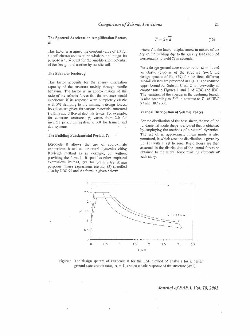
For a design ground acceleration ratio, a = 1 , and an elastic response of the ~ructure (q=i), th'e design spectra of Eq. (29) for the three different subsoil classes are presented in Fig. 3. The reduced upper bound for Subsoil Class C is noteworthy in comparison to Figures I and 2 of UBC and IBC. The variation of the spectra in the declining branch
. is also according to T 213 in contrast to .T 1 of UBC' 97 and IBC 2000.
Vertical Distribution of Seismic Forces
For the distribution of the base shear, the use of the fundamental mode shape is allowed that is obtain~ by employing the methods of structural dynamics. The use of an approximate linear mode is also 1permitted, in which case the distribution is given by Eq. (5) with Fi set to zero. Rigid floors are then assumed in the distribution of the lateral forces so obtained to the lateral force resist
1
ing elements of' each story.
Subsoil Class
2 2.5 3. 3.5
T(sec)
Figure 3 The design .spectra of Eurocode 8 for the ESF method of analysis for a design ground acceleration ratio, a = 1, and an elastic response of the structure (q=l)
Journal of EAEA~ Vol 18, 2001
22 Asrat Worku
Torsion
An accidental torsion of 5% is considered as in UBC and IBC. In case 01· symmetric distribution of lateral stiffness and mass, the Code allows for an alternative approach of accounting for accidental torsion, in which the action effects in the individual lateral load resisting elements are amplified by the following factor:
0 = 1 + 0.6xj Le (31)
where x is the element distance from the building center, and L. is the distance between the outermost lateral load resisting elements. Equation (31) is uncommon in UBC and IBC provisions, and its background is little known.
In structures with torsional irregularities, the code specifies the amplification of the accidental eccentricity by the factor A of Eq. (9) similar to the UBC specification.
Story Drift
The story drift limitations to be observed are d,.S0.004µh for buildings having nonstructural elements of brittle materials attached to the structure and d,S.0.006µh for buildings having nonstructural elements fixed in a way as not to interfere with structural deformations. In these requirements, h is the story height and µ is a reduction factor that takes into account the lower return period of the seismic event associated with the serviceability limit state. The reduction factor, µ, assumes the value of either 2.0 or 2.5 depending on the importance category.
P-delta Effects
The Code me.asures the P-delta influence by the moment ratio, e, defined in Eq. (I 0) as in UBC 94 and 97. It requires the consideration of the ?-delta effects if e is between 0.1 and 0.2 by increasing the relevant seismic action effects by the factorl /(1-8). The P-delta effects need not be considered if 9 is less than 0.1. On the other hand, Bis not allowed to exceed 0.3; but without explicitly stating what is to be done if Bexceeds this upper limit.
Journal of EAEA, Vol. 18, 2001
THE ETHIOPIAN BUILDING CODE STANDARD (EBCS 8-1995)
EBCS 8 - 1995 is the most recent code standard in Ethiopia dealing with seismic regulations. It is an independent volume covering topics ranging from general requirements on structural analysis and design to specific design provisions for concrete, steel and timber buildings [7]. The general regulations pertinent to the ESF method of analysis are discussed in the following sections.
Base Shear
The base shear for each main direction is determined by the same equation as that of Eurocode 8 given by Eq. (28). The coefficient SJ..T1) in this equation is, however, given in a different manner as given by:
(32)
This coefficient is the ordinate of the design spectrum normalized with respect to the gravitational acceleration, g. The three parameters in Eq. (32) are briefly discussed below.
The Design Bedrock Acceleration E.atio, a
This parameter is the ratio of the design bedrock acceleration to the gravitational acceleration and is given by
a= acJ (33)
In Eq. (J3), a0 is the bedrock acceleration ratio for the site that depends on four seismic zones provided. It assumes one of the values of 0: 10, 0.07, 0.05 or 0.03. I is the importance factoi;. that takes one of the values of 1.4, 1.2, 1.0 or 0.8.
The Design Response Factor, p
This fa,'l')r is gi ve'l by
fJ = 1.2S/ 'I'iX ~ 2.5 (34)
where S is the site coefficient fur soil characteristics that takes the value of 1.0, 1.2 or 1.5 depending on the soil ci?sses A, B, or C, respectively, described in the Code. While the descriptions of the three soil classes are identical to
Comparison, of Seismic Provisions 23
those given by Eurocode 8, the values assigned to the factor S are, however, significantly different.
The Fundamental Period, T1
The specifications of EBCS 8 for the computation of the period are essentially the same as those of
· Eurocode 8. ·
The Behavior Factor, r
This factor has the same purpose of accounting for the energy dissipation capacity of the structure, mainly through its ductile behavior, as the factor q of Eurocode 8. The code specifies its values for different. materials and structural systems. For concrete structures, it does not exceed the value pf 0.70; for steel structures, it ranges from 0.17 to I; for timber structures. it varies from . 0.3 to 1.0 depending on the structural system.
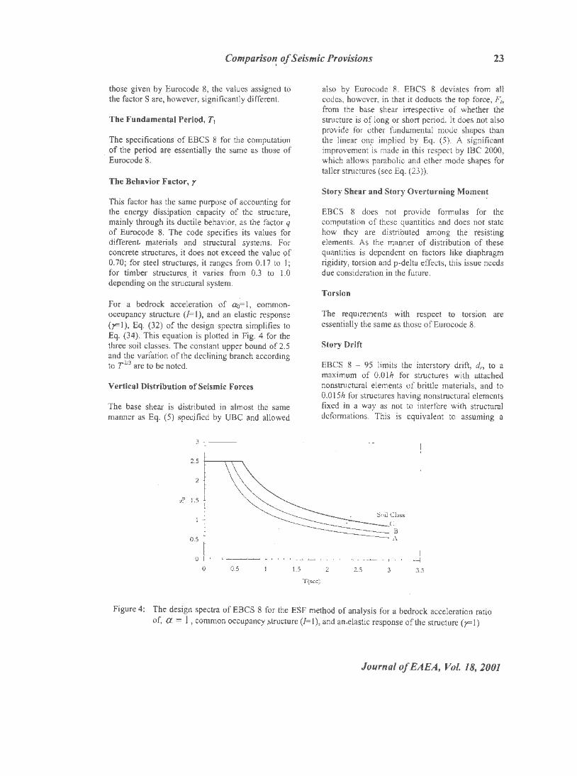
For a bedrock acceleration of r:1-0= 1, commonoccupancy structure (/=I), and an elastic response (F 1 ), Eq. (32) of the design spectra simplifies to Eq. (34). This equation is plotted in Fig. 4 for the three soil classes. The constant upper bound of 2.5 and the vari'ation of the declining branch according to T 213 are to be noted. . . ·
Vertical Distribution of Seismic Forces
The base shear is distributed in almost the same manner as Eq. (5) specjfied by UBC and allowed
also by Eurocode 8. EBCS 8 deviates from all codes, however, in that it deducts the top force, F,, from the base shear irrespective of whether the structure is of long or short period. It does not also provide for other fundamental mode shapes than the linear on~ implied by Eq. (5). A significant improvement is made in this respect by IBC 2000, which allows parabolic and other mode shapes for taller structures (see Eq. (23)).
Story Shear and Story Overturning Moment
EBCS 8 does not provide formulas for the computation of these quantities and does not state how they are distributed among the resisting elements. As the manner of distribution of these quantities is dependent on factors like diaphragm rigidity, torsion and p-delta effects, this issue needs due consideration in the future.
Torsion
The requirements with respect to torsion are essentially the same as those ofEurocode 8.
Story Drift
EBCS 8 - 95 limits the interstory drift, d,, to a maximum of O.Olh for structures with attached nonstructural elements of brittle materials, and to 0.015h for structures having nonstructural elements fixed in a way as not to interfere with structural deformations. This is equivalent to assuming a
0 +-<~~+-'~~-r-~~~~~'-t-~~~+~~--.~~--'--l
0 0.5 1.5 2 2.5 3 3.5
T (scc)
Figure 4: The design spectra of EBCS 8 for the ESF method of analysis for a bedrock acceleration ratio of, a = l , common occupancy .structure (I= 1), and an.elastic response of the structure (F 1)
Journal of BABA, Vol 18, 2001
24 Asrat Worku
value of2.5 to the reduction factor, p, employed in Eurocode 8. The displacements, d,, of the masses for this purpose are calculated from the elastic displacements, de, by dividing this by the behavior factor, y.
P-delta Effects
The requirements with respect to P-deha effects are the same as in Eurocode 8 with the sole difference in the upper limit of 8 . . EBCS 8 limits B to a maximum of 0.25 instead of 0.30 as specified by Eurocode 8.
CONCLUSIONS
On the basis of the comparative study .presented in the previous sections, the following major concluding remarks can be made:
I. A clear disparity exists in the definition of the seismic shear coefficient among the various codes studied. Even within the same code of UBC, the d~finition in UBC 94 is different from that of UBC 85, and th'at of UBC 97 is again different from both ·UBc 94 and UBC
· 85. A significant change in the definition of the seismic shear coefficient within the UBC series was introd1,1ced in UBC 88 and UBC 97. Almost all factors included in the seismic coefficient are modified drastically. The definition of EBCS 8 seems to have closer similarity. to that of UBC 94, especially with respect to the zone factors, than to the other codes considered. However, evident deviations exist in the definition of the other factors. Some EBCS 8 provisions ·share also common features with Eurocode 8.
2. Eurocode 8 definition of the seismic coefficient, tenned as the design spectrum in this code, does not neglect the left - linear branch, as do all the other codes. It also specifies a smaller upper bound of the seismic coefficient for the softest subsoil class, unlike the other codes, which employ the same upper bound for all kinds of soil profile.
3. EBCS 8 does not provide (but allows) closed form analytical expressions based on structural dynamics theory for the period computation like Rayleigh's quotient, which is provided by other codes like the UBC series. Besides, it does not set an upper bound to the period
Journal of EAEA, Vo/.18, 2001
computed using such analytical methods. In this regard it has similarity with Eurocode 8.
4. While the seismic coefficient in UBC 94, Eurocode 8 and EBCS 8 varies in accordance with l/T213 in the constant-vclociiy branch, that of UBC 97 and IBC 2000 varies according to lff. The latter is in agreement with the proposed design Spectra of Newmark and Hall [8,9], which is based on statistical analysis of ensembles of response spectra.
5. Only three different soil classes are considered by Eurocode 8 and EBCS 8, while four classes are considered by UBC 94 and six classes by the recent codes ofUBC 97 and IBC 2000.
6. The approach towards incorporating site effect in the base shear coefficient showed a drastic change in UBC 97 and IBC 2000. Especially the rationalized approach followed by IBC 2000 marks a milestone in both the quantitative technique of evaluating the soil profile as well as in the manner of incorporation of the site effect on the base shear coefficient.
7: In the vertical distribution of the base shear, EBCS 8 deviates from all the other codes in that it subtracts the top force, F., from the base shear irrespective of the magnitude of the fundamental period.
8. IBC 2000 introduced quite a new approach of quantifying seismic hazard of sites. It replaced the classical zoning of regions on the basis of peak bedrock acceleration by the new contour . map of spectral accelerations on the surface for short and one-second period. This recent approach has the advantage, among others, of assigning spectra to any site by interpolating between successive contour lines in contrast to the constant value of the zone factor assigned to all sites within a zone in the older zonebased mapping. This approach can heavily influence the approach of seismic hazard mapping to be followed by EBCS in the future.
9. For the distribution of the base shear, IBC 2000 employs a linear mode for structures of short period only (T~0.5 sec). For all other s~ructures it uses a nonlinear fundamental mode as a basis. All the other codes are based on a linear fundamental mode. This is once
Comparison of Seismic Provisions 25
again an important development and more realistic.
I 0. IBC 2000 uses redui:ed overturning moments in lower stories of buildings taller than I 0 stories. No such reduction is made by the other codes.
11. The requirements and provisions of l::.BCS 8 with respect to torsion, story dnft and P-dclta effects are similar to those of Eurocodc 8 with some differences in the upper limits of the story drift and the moment ratio. The corresponding regulations of IBC 2000 exhibit, however, a significant difference from both codes and even from UBC 97.
ACKNOWLEDGMENT
The author would like to pass his sincere thanks to Dr. Samuel Kinde of Nanogen Inc., San Diego, California, for he kindly provided a set of invaluable reference material that helped a lot in the compilation of this work. The communication with him was also very encouraging and constructive.
REFERENCE
(!) Paz, M., Structural Dynamics - Theory and Computation, 4th edition, Chapman & Hall, 1997.
(2) Di Julio, R., "Static Lateral Force Procedures," in the Seismic Design Handbook, ed. Naeim, F., Van Nostrand, 1987.
[3] International ~onfcrence of Building Officials, Stn1ctura/ Engineering Design Provisions, Unifonn Building Code (UBC), 1997.
[4) International Conference of Building Officials, Structural E11g111eering Provision, 2000 International Building Code, 2000.
(5) Federal Emergency Management Agency, NEHRP Recommended Provisions for Seismic Regulation of New Buildings,.1997.
(6) European Committee for Standardization, Eurocode 8 Design Provisions for Earthquake Resistance of Structures (ENV 1998), May 1994.
[7] Ministry of Works and Urban Development, Design of Structures for Earthquake Resistance, Ethiopian Building Code Standard (EBCS 8), Addis Ababa, 1995.
[8] Worku, A., "Assessment of Important Seismic Provisions of EBCS 8 1995 from Structural Dynamics Perspective," Zede - Journal of the Ethiopian Engineers and Architects, PP 43-55, Vol. 17, 2000.
(9) Chopra, A., Dynamics of Structures - Theory and Application to Earthquake Engineering, Prentice-Hall, 1995.
Journal of EAEA, Vol. 18, 2001