Embed Size (px)
Citation preview
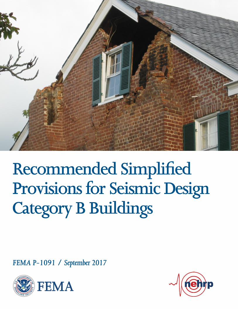
Recommended Simpliÿed Provisions for Seismic Design Category B Buildings
FEMA P-1091 / September 2017

FEMA P-1091
Recommended Simplified Provisions for
Seismic Design Category B Buildings
Prepared by
APPLIED TECHNOLOGY COUNCIL 201 Redwood Shores Parkway, Suite 240
Redwood City, California 94065 www.ATCouncil.org
Prepared for
FEDERAL EMERGENCY MANAGEMENT AGENCY Mai (Mike) Tong, Task Monitor
Michael Mahoney, Project Officer Washington, D.C.
APPLIED TECHNOLOGY COUNCIL Jon A. Heintz LEAD AUTHOR Peter Somers
PROJECT REVIEW PANEL William T. Holmes John D. Hooper Kevin Moore
September 2017
Notice
Any opinions, findings, conclusions, or recommendations expressed in this publication do not necessarily reflect the views of the Applied Technology Council (ATC), the Department of Homeland Security (DHS), or the Federal Emergency Management Agency (FEMA). Additionally, neither ATC, DHS, FEMA, nor any of their employees, makes any warranty, expressed or implied, nor assumes any legal liability or responsibility for the accuracy, completeness, or usefulness of any information, product, or process included in this publication. Users of information from this publication assume all liability arising from such use. Cover image: Cuckoo House, located in a region of low seismicity, which was damaged in the 2011 magnitude 5.8 Mineral, Virginia earthquake (photo by Jim Beavers, provided courtesy of the Earthquake Engineering Research Institute).
FEMA P-1091 Foreword iii
Foreword
Simplification of seismic design provisions for buildings is desirable for
anyone who uses the seismic provisions of the building code, including
structural engineers and local building officials. This goal has been explored
in various ways over decades through efforts supported by the Federal
Emergency Management Agency (FEMA) as part of its responsibilities under
the National Earthquake Hazards Reduction Program (NEHRP) through the
FEMA-funded NEHRP Provisions Update Committee as well as through
other code development organizations such as the American Society of Civil
Engineers/Structural Engineering Institute (ASCE/SEI) 7 Seismic
Subcommittee, as summarized in the Appendix of this document.
Simplification is a continuing effort in the earthquake engineering
community. Despite many alternative approaches, directly simplifying
building code requirements is challenging in that simplicity must not weaken
the seismic performance of buildings while striving to maintain general
applicability. For Seismic Design Category (SDC) B, which designates a
low seismic hazard region, structural engineers still need to complete a full
seismic design process to meet the building code requirements. Seismic
design is necessary because earthquakes are a hazard with long return periods
and large uncertainties, and the sudden occurrence of earthquakes in SDC B
regions, such as the 2011 Mineral, Virginia earthquake, can cause significant
damage or collapse if buildings are not properly designed for seismic
resistance. The recommended simplified seismic design provisions described
in this FEMA NEHRP document aim to assist structural designers in meeting
building code requirements for ordinary SDC B buildings without wading
through the full, complex seismic design process in ASCE/SEI 7.
Forty four of the fifty states in the United States have areas classified as SDC
B. It is important that Authorities Having Jurisdiction (AHJ) adopt and
enforce the adequate building codes and consensus design standards for
protection of buildings from earthquakes and other natural hazards, and that
design engineers fully comply with code requirements for hazard resistance.
FEMA is committed to providing technical resources for communities at risk
from earthquakes to correctly and effectively mitigate and reduce the risks
associated with this hazard.
iv Foreword FEMA P-1091
FEMA is greatly appreciative of the Applied Technology Council and all
who contributed to this document. A list of participants on this project is
provided in the back of this document. Improving seismic safety of buildings
is a collective endeavor of many dedicated professionals, organizations, and
local communities; we strongly encourage full and effective implementation
of national design standards and building codes, and look forward to this
document helping reduce code complexity and increase seismic resilience in
relevant at-risk communities.
Federal Emergency Management Agency
Preface
In 2016, under Federal Emergency Management Agency (FEMA) “Seismic
Technical Guidance Development and Support” contract (HSFE60-12-D-
0242), the Applied Technology Council (ATC) was awarded Task Order
HSFE60-16-J-0237 entitled “Technical Monitoring of New and Existing
Seismic Building Codes and Related Training” (ATC-136 Project). The
purpose of this project was to continue FEMA’s support of the model codes
and consensus standards development processes, and to support other code-
related activities such as outreach and education to ensure that seismic risk is
adequately addressed at the state and local levels.
In 2009, through the Building Seismic Safety Council (BSSC) of the
National Institute of Building Sciences (NIBS), FEMA initiated a study of
seismic code provision simplifications. The Simplified Seismic Design
Procedures Project was intended to generate simplifications to the 2015
National Earthquake Hazards Reduction Program (NEHRP) Recommended
Seismic Provisions for New Buildings and Other Structures. This project
resulted in the development of specific seismic design requirements for
Seismic Design Category B (SDC B) buildings. These requirements were
based on editorial deletions of provisions that are not applicable to SDC B
buildings, judgmental deletions of provisions that are rarely, if ever, used for
SDC B buildings, and technical simplifications validated through the use of
FEMA P-695, Quantification of Building Seismic Performance Factors, to
demonstrate equivalency.
The simplified provisions were included as Chapter 24 of the 2015 NEHRP
Provisions, but they were not adopted into ASCE/SEI 7-16, Minimum Design
Loads and Associated Criteria for Buildings and Other Structures. To make
these provisions available to design engineers, local building officials, the
2020 BSSC Provisions Update Committee (PUC), and others in the
development of future simplified seismic design provisions, FEMA
commissioned this work under the ATC-136 Project to update Chapter 24 for
consistency with ASCE/SEI 7-16, and to publish the resulting provisions as a
stand-alone document for future reference.
ATC is indebted to the leadership of Peter Somers, who served as lead author
for the work, and to the members of the Project Review Panel, including Bill
FEMA P-1091 Preface v
Holmes, John Hooper, and Kevin Moore, for their efforts in reviewing and
advising on the resulting changes.
ATC also gratefully acknowledges Mai (Mike) Tong (FEMA Task Monitor)
and Mike Mahoney (FEMA Project Officer) for their input and guidance in
the preparation of this report, and Carrie Perna for ATC report production
services.
Jon A. Heintz
ATC Executive Director
Preface FEMA P-1091 vi
FEMA P-1091 Table of Contents vii
Table of Contents
Foreword ....................................................................................................... iii
Preface .............................................................................................................v
1. Introduction ...................................................................................... 1-1 1.1 Background and Purpose .......................................................... 1-1
1.1.1 Scope of Chapter 24 Provisions .................................. 1-2 1.1.2 Building Seismic Safety Council Development .......... 1-2 1.1.3 Trial Design Studies .................................................... 1-4
1.2 Updates Based on ASCE/SEI 7-16........................................... 1-5 1.3 Use of Chapter 24 Provisions ................................................... 1-5
1.3.1 Alternative to Seismic Design Provisions ................... 1-5 1.3.2 Applicability to Building Codes .................................. 1-6
2. Simplified Provisions and Commentary ........................................ 2-1 2.1 Chapter 24 Alternative Seismic Design Requirements for
Seismic Design Category B Buildings ..................................... 2-1 2.2 Figures and Tables for Chapter 24 Alternative Seismic
Design Requirements for Seismic Design Category B Buildings ................................................................................ 2-23
2.3 Commentary to Chapter 24 Alternative Seismic Design Requirements for Seismic Design Category B Buildings ...... 2-29
3. Recommendations for Future Improvement ................................. 3-1 3.1 Introduction .............................................................................. 3-1 3.2 Recommendations .................................................................... 3-2
3.2.1 Structural Systems Included in the Procedure ............. 3-2 3.2.2 Analysis Procedures and Requirements ...................... 3-2 3.2.3 Configuration Requirements ....................................... 3-3 3.2.4 Foundations ................................................................. 3-4
Appendix A: Simplification of Seismic Code Provisions ....................... A-1 A.1 Introduction ............................................................................. A-1 A.2 New Studies Began in 2009 .................................................... A-3 A.3 Framework Report ................................................................... A-4
A.3.1 Further Simplification of ASCE/SEI 7-10, Section 12.14 .............................................................. A-4
A.3.2 Development of Stand-Alone Design Provisions for Low and Moderate Seismic Regions .......................... A-5
A.3.3 Development of Stand-Alone Design Provisions for Low Seismic Regions ................................................. A-5
A.3.4 Development of Stand-Alone Design Provisions for Buildings with Rigid Walls and Flexible Diaphragms ................................................................ A-5
viii Table of Contents FEMA P-1091
A.3.5 Development of Stand-Alone Design Provisions for Wood-Frame Buildings .............................................. A-6
A.3.6 Use of the Ratio of Bearing Walls to Floor Area as a Primary Design Requirement ................................... A-7
A.3.7 Reduce Material Detailing Requirements (to Achieve Ductility) with Use of Lower R Factors ....... A-7
A.3.8 Options Studied .......................................................... A-8 A.3.9 Conclusions from the Simplified Seismic Design
Provisions Project (2009-2015) ................................ A-15 A.4 Other Efforts to Simplify Seismic Design Procedures .......... A-16 A.5 The Future of Simplified Seismic Design Provisions ............ A-17 A.6 Acknowledgments ................................................................. A-18
References .................................................................................................. B-1
Project Participants ................................................................................... C-1
FEMA P-1091 1: Introduction 1-1
Chapter 1
Introduction
1.1 Background and Purpose
Code complexity has become an issue in recent years, and seismic provisions
are no exception. Part of the issue is that engineers in regions of low
seismicity are required to read and interpret complex seismic provisions
intended for regions of high seismicity because the design requirements for
all seismic design categories are presented together.
To help remedy this problem, a new Chapter 24, entitled Alternative Seismic
Design Requirements for Seismic Design Category (SDC) B Buildings, was
developed and subsequently approved for the 2015 National Earthquake
Hazards Reduction Program (NEHRP) Recommended Seismic Provisions for
New Buildings and Other Structures (FEMA, 2015a). Seismic Design
Category B (SDC B) structures are located in regions of low seismicity, and
include all buildings in these areas except Risk Category IV (essential
occupancies). The area covered by SDC B design criteria applies to much of
the densely populated eastern United States, so a very large number of
buildings would potentially be affected. Chapter 24 was intended to provide
separate seismic provisions in Seismic Design Category B, so that engineers
could design SDC B buildings without having to “wade through” all of the
provisions related to higher seismic design categories that are not applicable
to SDC B buildings.
The purpose of this publication is to summarize and explain the development
of simplified seismic design provisions, update the current Chapter 24
provisions for consistency with ASCE/SEI 7-16, Minimum Design Loads and
Associated Criteria for Buildings and Other Structures (ASCE, 2016), and
recommend possible future updates based on currently available information.
It has three main parts, as follows:
Introduction to the simplified provisions (Chapter 1)
Updated Chapter 24 provisions and commentary (Chapter 2)
Recommendations for future updates to the simplified provisions
(Chapter 3)
1-2 1: Introduction FEMA P-1091
When excerpted from the NEHRP Provisions, “Chapter 24” has little
meaning, but the numbering and formatting of Chapter 24 has been retained
in this publication for future reference, and to remind readers of its source.
1.1.1 Scope of Chapter 24 Provisions
When taken in their entirety, the seismic design requirements in Chapter 24
of the NEHRP Provisions were judged equivalent to those in Chapters 12
and 13 of ASCE/SEI 7-10, Minimum Design Loads for Buildings and Other
Structures (ASCE, 2010) for SDC B buildings by the 2010-2015 Provisions
Update Committee (PUC). The Chapter 24 requirements in this report have
been updated for consistency with ASCE/SEI 7-16, and are judged to have a
similar degree of equivalence (see Section 1.2).
The simplified provisions in Chapter 24 are considered equivalent to the
procedures in ASCE/SEI 7, but differ in two ways. First, the text and
requirements presented in Chapter 24 are substantially shorter and less
complex, because the chapter has been editorially simplified to include only
those requirements that apply in Seismic Design Category B. Second, some
of the seismic design requirements have been eliminated, or simplified, based
on technical study.
The provisions in Chapter 24 are required to be followed in their entirety
without exception. If designers choose to use any provisions in Chapters 12
or 13 of ASCE/SEI 7 that are not included in Chapter 24, then the design
must comply with all of the requirements for SDC B structures in Chapters
12 and 13. It should be noted that the Chapter 24 provisions are completely
separate from the simplified design procedure in Section 12.14 of ASCE/SEI
7, which can be used for all Seismic Design Categories.
The Chapter 24 provisions do not modify in any way the material-specific
requirements and material design standards referenced in Chapter 14 of
ASCE/SEI 7. Nonbuilding structures (Chapter 15 of ASCE/SEI 7),
seismically isolated structures (Chapter 17 of ASCE/SEI 7), and structures
with damping systems (Chapter 18 of ASCE/SEI 7) are not permitted to be
designed using the alternative provisions in Chapter 24.
1.1.2 Building Seismic Safety Council Development
Beginning in 2009, through the Building Seismic Safety Council (BSSC) of
the National Institute of Building Sciences (NIBS), FEMA initiated a new
study of seismic code provision simplifications that was intended to be more
comprehensive than previous studies. The Simplified Seismic Design
Procedures Project was primarily intended to generate simplifications to the

FEMA P-1091 1: Introduction 1-3
2015 NEHRP Provisions, but was also intended to test the viability of
various methods of simplification, including the use of stand-alone
provisions for individual building types, and the use of procedures in FEMA
P-695, Quantification of Building Seismic Performance Factors (FEMA,
2009) to prove equivalency. The study included review of input on the
subject received by FEMA since 2000, articles and papers discussing
simplified design, new input from different regions of the country, and
consideration of various resources currently available to assist engineers with
seismic design.
Several options for simplification were identified. In general, the project
focused on simplification of the provisions in the main body of code
requirements contained in the NEHRP Provisions, particularly those
considering the capabilities of FEMA P-695. Obvious opportunities to
simplify, or eliminate, material-specific detailing requirements were also
considered. A summary of Simplified Seismic Design Procedures Project is
provided in Appendix A.
One option consisted of the development of specific seismic design
requirements for SDC B buildings. These requirements could be developed
in a stand-alone document, or as a special section of the current seismic
design provisions. In either case, only the seismic design requirements for
SDC B would be included, and the resulting provisions would be expected to
be much shorter than provisions covering all Seismic Design Categories.
This option could be pursued by editorial or technical changes to the seismic
design requirements in ASCE/SEI 7-10.
In this study, several concepts were considered for minimizing the provisions
needed to design SDC B buildings:
Editorial Deletions. Provisions that are not applicable to SDC B
structures could simply be removed. For example, there are nine pages
of provisions covering nonstructural components in ASCE/SEI 7, but
only parapets and exit stairs are specifically addressed in Seismic Design
Category B. As a result, the necessary nonstructural provisions for SDC
B structures could be covered in less than one page of material.
Judgmental Deletions. Because SDC B provisions are intended to be an
option to the use of the full code, provisions that are rarely, if ever, used
could also be removed. If needed in rare cases, or for an unusual
building, the provisions of the full code could always be implemented.
As an example, there are many structural systems listed in the “R-factor
table” (officially titled, “Design Coefficients and Factors for Seismic
Force-Resisting Systems”) that are never, or rarely, used in Seismic
1-4 1: Introduction FEMA P-1091
Design Category B. These include archaic systems (e.g., plain concrete
shear walls) and high ductility systems (e.g., special moment frames of
concrete or steel). As a result, the R-factor table for SDC B structures
could be reduced from 83 systems to 36 systems.
Technical Simplifications. The availability of FEMA P-695 created a
method for evaluating the significance of potential technical
simplifications and for determining the equivalency of technical changes.
As one example, FEMA P-695 analyses were used to determine that
consideration of accidental torsion is not required unless the building has
an Extreme Torsional Irregularity.
The Simplified Seismic Design Procedures Project resulted in acceptance of
a proposal to add a stand-alone chapter to the 2015 NEHRP Provisions for
design of SDC B buildings. The resulting simplified provisions consisted of
35 pages as an alternate to the full seismic provisions, which were spread
over 11 chapters comprising 87 pages.
1.1.3 Trial Design Studies
To test the merit of the concept and efficiency of the technical changes, four
engineering firms practicing in SDC B regions were commissioned to
perform trial designs using the simplified provisions (BSSC, 2015). The
buildings used in the trial designs were previously designed using the full
provisions of the code. Trial design buildings included the following seismic
systems:
a three-story steel moment frame (R = 3);
a four-story wood light-frame shear wall (R = 6.5);
a four-story ordinary reinforced concrete shear wall (R = 4);
a six-story steel braced frame (R = 3).
The results of the trial design studies can be summarized as follows:
The resulting designs did not differ significantly from the original
designs completed using the full provisions of the code.
The stand-alone format was viewed very favorably. Trial design
engineers suggested that such a format would prevent omissions of
requirements and prevent confusion over mixing requirements from
different Seismic Design Categories. Trial design engineers uniformly
reported that they would use such provisions if they were code-approved.
Most trial design engineers suggested additional judgmental deletions to
further simplify the provisions on the basis that the referenced provisions
FEMA P-1091 1: Introduction 1-5
were seldom used. These recommendations are addressed in Chapter 3
of this publication.
1.2 Updates Based on ASCE/SEI 7-16
In this publication, Chapter 24 of the 2015 NEHRP Provisions (originally
developed to be compatible with ASCE/SEI 7-10) have been updated for
consistency with ASCE/SEI 7-16. In performing these updates, the
following approaches were used:
Updates were made to Chapter 24 to match technical changes to the same
sections in ASCE/SEI 7-16 Chapter 12.
Following the same logic used in the development of the original
Chapter 24 (see Section 1.1.2), some judgement was utilized in
determining which updates in ASCE/SEI 7-16 Chapter 12 were
appropriate for inclusion in the provisions for SDC buildings. Specific
examples are listed below.
There were no changes to ASCE/SEI 7-16 Chapter 13 for SDC B, so the
nonstructural portion of Chapter 24 remained unchanged.
There were several significant updates in ASCE/SEI 7-16 Chapter 12 that
could be applicable to SDC B buildings, but were not incorporated into
Chapter 24 of this publication because they were judged to be unnecessary
for SDC B or not commonly used in SDC B. The following changes in
ASCE/SEI 7-16 Chapter 12 were not included in Chapter 24:
Alternate Structural Systems (Section 12.2.1.1)
Linear Response History Analysis (Section 12.9.2)
Strength Design for Foundation Geotechnical Capacity (Section 12.13.5)
Provisions contained in ASCE/SEI 7-16 Chapters 12 and 13, which have not
been explicitly included in Chapter 24, cannot be used in conjunction with
Chapter 24 provisions for design.
1.3 Use of Chapter 24 Provisions
1.3.1 Alternative to Seismic Design Provisions
Chapter 24 provisions are intended as an alternate to seismic design
provisions contained in ASCE/SEI 7-16 Chapters 12 and 13. Chapter 24
provisions, however, are not fully self-contained, and the use of Chapter 24
still requires the use of other chapters in ASCE/SEI 7-16. To use Chapter 24,
ASCE/SEI 7-16 Chapter 11 must first be used to determine seismic ground
motions (Section 11.4), importance factor and risk category (Section 11.5),
1-6 1: Introduction FEMA P-1091
and seismic design category (Section 11.6). Additionally, loads calculated in
accordance with Chapter 24 provisions must be used considering ASCE/SEI
7-16 Chapter 2, Combinations of Loads.
Once Seismic Design Category B is confirmed, then, in accordance with
ASCE/SEI 7-16 Section 11.1.4, engineers may choose to use Chapter 24 as
an alternate to ASCE/SEI 7-16 Chapters 12 and 13. Use of Chapter 24 is
subject to the following limitations:
The selected seismic force-resisting system must be listed in Table
24.3-1.
The analysis must be based on one of the procedures listed in Section
24.7.
The seismic design of nonstructural components is limited to egress
stairways, and parapets, which are the minimum requirements in SDC B.
All of the provisions of Chapter 24 must be followed, and no provisions,
exceptions, or alternates contained in ASCE/SEI 7-16 Chapters 12 and
13 are permitted. There must not be any mixing of Chapter 24
provisions and ASCE/SEI 7-16 Chapters 12 and 13 provisions.
Additional information on the application and limitations of this procedure
are contained in the Chapter 24 text and commentary provided in Chapter 2
of this publication.
1.3.2 Applicability to Building Codes
To regulate building construction in the United States, Chapter 24 provisions
must be specifically adopted into an applicable building code, or adopted into
a reference standard, such as ASCE/SEI 7-16. A change to adopt Chapter 24
provisions into ASCE/SEI 7 was proposed in 2014, but this proposal was not
successful because of arguments that: (1) simplification of the seismic code
was not needed; and (2) parallel methods of design represented by a stand-
alone chapter would create unwarranted ongoing risk of inconsistent
updating and potential for a double standard. At present, engineers that want
to use Chapter 24 provisions will need to obtain approval from local building
officials regarding equivalency and acceptability based on the Alternate
Materials and Methods of Construction provisions in Section 11.1.4 of
ASCE/SEI 7-16.
FEMA P-1091 2: Simplified Provisions and Commentary 2-1
Chapter 2
Simplified Provisions and Commentary
This chapter contains the full text and commentary of Chapter 24 Alternate
Seismic Design Requirements for Seismic Design Category B Buildings,
updated for consistency with ASCE/SEI 7-16. The provisions and
commentary herein maintain the Chapter 24 format and numbering for
consistency with the 2015 NEHRP Provisions. References to chapter,
section, table, figure, and equation numbers that are not in Chapter 24, are
referring to the relevant chapters, sections, tables, figures, and equations in
ASCE/SEI 7-16.
2.1 Chapter 24 Alternative Seismic Design Requirements for Seismic Design Category B Buildings
24.1 GENERAL
24.1.1 Scope and Applicability
The seismic analysis and design requirements in this chapter are permitted to be used in lieu of the requirements in Chapter 12 and Chapter 13 for the seismic analysis and design of structures assigned to Seismic Design Category B and for the design of parapets and egress stairways attached to those structures. Nonbuilding structures as defined in Chapter 15 and below, seismically isolated structures as defined in Chapter 17, and structures with damping systems as defined in Chapter 18, are not permitted to be designed by the procedures in this chapter.
Where the weight of a nonstructural component is greater than or equal to 25 percent of the effective seismic weight, W, of the structure as defined in Section 24.8.2, the component shall be classified as a nonbuilding structure and is not permitted to be designed in accordance with Chapter 24.
24.1.2 Symbols
The unit dimensions used with the items covered by the symbols shall be consistent throughout except where specifically noted. Symbols presented in this section apply only to the seismic provisions of Chapters 24.
ap = the amplification factor related to the response of a system or component as affected by the type of seismic attachment, determined in Section 24.15.3
Cd = deflection amplification factor as given in Tables 24.3-1
Cs = seismic response coefficient determined in Section 24.9.1.1 (dimensionless)
Ct = building period coefficient in Section 24.9.2.1
2-2 2: Simplified Provisions and Commentary FEMA P-1091
Cvx = vertical distribution factor as determined in Section 24.9.3
D = the effect of dead load
Dp = relative seismic displacement that a component must be designed to accommodate (Section 24.15.4)
DpI = seismic relative displacement; see Section 24.15.4
E = effect of horizontal and vertical earthquake-induced forces (Section 24.5)
Em = seismic load effect including overstrength factor (Section 24.5.3)
Fa = short-period site coefficient (at 0.2-s period); see ASCE/SEI 7-16 Section 11.4.3
Fi, Fn, Fx = portion of the seismic base shear, V, induced at level i, n, or x, respectively, as determined in Section 24.9.3
Fp = the seismic force acting on a component of a structure as determined in Sections 24.12.1 and 24.15.3
Fpx = diaphragm seismic design force at Level x
Fv = long-period site coefficient (at 1.0-s period); see ASCE/SEI 7-16 Section 11.4.3
G = s2/g = the average shear modulus for the soils beneath the foundation at
large strain levels (psf or Pa)
g = acceleration due to gravity
h = average roof height of structure with respect to the base; see Section 24.15
hi, hx = the height above the base to level i or x, respectively
hn = structural height as defined in ASCE/SEI 7-16 Section 11.2
hsx = the story height below level x = (hx – hx–1)
Ie = the importance factor as prescribed in ASCE/SEI 7-16 Section 11.5.1
i = the building level referred to by the subscript i; i = 1 designates the first level above the base
k = distribution exponent given in Section 24.9.3
ka = coefficient defined in Sections 24.12.2
Lf = the span, in feet, of a flexible diaphragm that provides the lateral support for the wall;
Mt = torsional moment resulting from eccentricity between the locations of center of mass and the center of rigidity (Section 24.9.4.1)
Mta = accidental torsional moment as determined in Section 24.9.4.2
n = designation for the level that is uppermost in the main portion of the building
Pf = flat roof snow load
Px = total unfactored vertical design load at and above level x, for use in Section 24.9.7
QE = effect of horizontal seismic (earthquake-induced) forces
FEMA P-1091 2: Simplified Provisions and Commentary 2-3
R = response modification coefficient as given in Tables 24.3-1
Rp = component response modification factor as defined in Section 24.15.3
S1 = mapped MCER, 5% damped, spectral response acceleration parameter at a period of 1 s as defined in ASCE/SEI 7-16 Section 11.4.1
SDS = design, 5% damped, spectral response acceleration parameter at short periods as defined in ASCE/SEI 7-16 Section 11.4.4
SD1 = design, 5% damped, spectral response acceleration parameter at a period of 1 s as defined in ASCE/SEI 7-16 Section 11.4.4
T = the fundamental period of the building
Ta = approximate fundamental period of the building as determined in Section 24.9.2
V = total design lateral force or shear at the base
Vt = design value of the seismic base shear as determined in Section 24.10.4.1
Vx = seismic design shear in story x as determined in Section 24.9.4
W = effective seismic weight of the building as defined in Section 24.8.2.
Wp = component operating weight or weight of wall tributary to an anchor (lb or N)
Wpx = weight tributary to the diaphragm at Level x
wi, wn, wx = portion of W that is located at or assigned to level i, n, or x, respectively
x = level under consideration, 1 designates the first level above the base
x = building period coefficient in Section 24.9.2.1
z = height in structure of point of attachment of component with respect to the base; see Section 24.15.3
β = ratio of shear demand to shear capacity for the story between levels x and x – 1
= design story drift as determined in Section 24.9.6
a = allowable story drift as specified in Section 24.13.1
ADVE = average drift of adjoining vertical elements of the seismic force-resisting system over the story below the diaphragm under consideration, under tributary lateral load equivalent to that used in the computation of MDD Fig. 24.4-1 (in. or mm)
MDD = computed maximum in-plane deflection of the diaphragm under lateral load, Fig. 24.4-1 (in. or mm)
max = maximum displacement at level x, considering torsion, Section 24.13.3
M = maximum inelastic response displacement, considering torsion, Section 24.13.3
MT = total separation distance between adjacent structures on the same property, Section 24.13.3
x = deflection of level x at the center of the mass at and above level x, Eq. (24.9-9)
2-4 2: Simplified Provisions and Commentary FEMA P-1091
xe = deflection of level x at the center of the mass at and above level x determined by an elastic analysis, Section 24.9.6
= stability coefficient for P-delta effects as determined in Section 24.9.7
max = maximum value of stability coefficient for P-delta effects
0 = overstrength factor as defined in Tables 24.3-1
24.2 STRUCTURAL DESIGN BASIS
24.2.1 Basic Requirements
The building structure shall include complete lateral and vertical force-resisting systems capable of providing adequate strength, stiffness, and energy dissipation capacity to withstand the design ground motions within the prescribed limits of deformation and strength demand. The design ground motions shall be assumed to occur along any horizontal direction of a building structure. The adequacy of the structural systems shall be demonstrated through the construction of a mathematical model and evaluation of this model for the effects of design ground motions. The design seismic forces, and their distribution over the height of the building structure, shall be established in accordance with one of the applicable procedures indicated in Section 24.7 and the corresponding internal forces and deformations in the members of the structure shall be determined. An approved alternative procedure shall not be used to establish the seismic forces and their distribution unless the corresponding internal forces and deformations in the members are determined using a model consistent with the procedure adopted.
24.2.2 Member Design, Connection Design, and Deformation Limit
Individual members, including those not part of the seismic force–resisting system, shall be provided with adequate strength to resist the shears, axial forces, and moments determined in accordance with this standard, and connections shall develop the strength of the connected members or the forces indicated in Section 24.2.1. The deformation of the structure shall not exceed the prescribed limits where the structure is subjected to the design seismic forces.
24.2.3 Continuous Load Path and Interconnection
A continuous load path, or paths, with adequate strength and stiffness shall be provided to transfer all forces from the point of application to the final point of resistance. All parts of the structure between separation joints shall be interconnected to form a continuous path to the seismic force-resisting system, and the connections shall be capable of transmitting the seismic force (Fp) induced by the parts being connected. Any smaller portion of the structure shall be tied to the remainder of the structure with elements having a design strength capable of transmitting a seismic force of 5 percent of the weight of the smaller portion. This connection force does not apply to the overall design of the seismic force-resisting system. Connection design forces need not exceed the maximum forces that the structural system can deliver to the connection.
24.2.4 Connection to Supports
A positive connection for resisting a horizontal force acting parallel to the member shall be provided for each beam, girder, or truss either directly to its supporting elements, or to slabs designed to act as diaphragms. Where the connection is through a diaphragm, then the member’s supporting element must also be connected to the diaphragm. The connection shall have a minimum design strength of 5 percent of the dead plus live load reaction.
FEMA P-1091 2: Simplified Provisions and Commentary 2-5
24.2.5 Foundation Design
The foundation shall be designed to resist the forces developed and accommodate the movements imparted to the structure by the design ground motions. The dynamic nature of the forces, the expected ground motion, the design basis for strength and energy dissipation capacity of the structure, and the dynamic properties of the soil shall be included in the determination of the foundation design criteria. The design and construction of foundations shall comply with Section 24.14.
When calculating load combinations using the load combinations specified in ASCE/SEI 7-16 Sections 2.3 or 2.4, the weights of foundations shall be considered dead loads in accordance with ASCE/SEI 7-16 Section 3.1.2. The dead loads are permitted to include overlying fill and paving materials
24.2.6 Material Design and Detailing Requirements
Structural elements including foundation elements shall conform to the material design and detailing requirements set forth in Chapter 14.
24.3 STRUCTURAL SYSTEM SELECTION
24.3.1 Selection and Limitations
The basic lateral and vertical seismic force-resisting system shall conform to one of the types indicated in Table 24.3-1 or a combination of systems as permitted in Sections 24.3.2, 24.3.3, and 24.3.4. Each type is subdivided by the types of vertical elements used to resist lateral seismic forces. The structural system used shall be in accordance with the structural system limitations and the limits on structural height, hn, contained in Table 24.3-1. The appropriate response modification coefficient, R, overstrength factor, 0, and the deflection amplification factor, Cd, indicated in Table 24.3-1 shall be used in determining the base shear, element design forces, and design story drift.
Each selected seismic force-resisting system shall be designed and detailed in accordance with the specific requirements for the system as set forth in the applicable reference document listed in Table 24.3-1 and the additional requirements set forth in ASCE/SEI 7-16 Chapter 14 material-specific design and detailing requirements.
24.3.2 Combinations of Framing Systems in Different Directions
Different seismic force-resisting systems are permitted to be used to resist seismic forces along each of the two orthogonal axes of the structure. Where different systems are used, the respective R, Cd, and 0 coefficients shall apply to each system, including the structural system limitations contained in Table 24.3-1.
24.3.3 Combinations of Framing Systems in the Same Direction
Where different seismic force-resisting systems are used in combination to resist seismic forces in the same direction, other than those combinations considered as dual systems, the most stringent applicable structural system limitations contained in Table 24.3-1 shall apply and the design shall comply with the requirements of this section.
24.3.3.1 R, Cd, and Ω0Values for Vertical Combinations
Where a structure has a vertical combination in the same direction, the following requirements shall apply:
1. Where the lower system has a lower Response Modification Coefficient, R,
2-6 2: Simplified Provisions and Commentary FEMA P-1091
the design coefficients (R, 0, and Cd) for the upper system are permitted to be used to calculate the forces and drifts of the upper system. For the design of the lower system, the design coefficients (R, 0, and Cd) for the lower system shall be used. Forces transferred from the upper system to the lower system shall be increased by multiplying by the ratio of the higher response modification coefficient to the lower response modification coefficient.
2. Where the upper system has a lower Response Modification Coefficient, the Design Coefficients (R, 0, and Cd) for the upper system shall be used for both systems.
EXCEPTIONS: 1. Rooftop structures not exceeding two stories in height and 10 percent of the
total structure weight. 2. Other supported structural systems with a weight equal to or less than 10
percent of the weight of the structure. 3. Detached one- and two-family dwellings of light-frame construction.
24.3.3.2 Two Stage Analysis Procedure
A two-stage equivalent lateral force procedure is permitted to be used for structures having a flexible upper portion above a rigid lower portion, provided the design of the structure complies with all of the following:
The stiffness of the lower portion shall be at least 10 times the stiffness of the upper portion.
The period of the entire structure shall not be greater than 1.1 times the period of the upper portion considered as a separate structure supported at the transition from the upper to the lower portion.
The upper portion shall be designed as a separate structure using the appropriate value of R.
The lower portion shall be designed as a separate structure using the appropriate value of R. The reactions from the upper portion shall be those determined from the analysis of the upper portion amplified by the ratio of R of the upper portion over R of the lower portion. This ratio shall not be less than 1.0.
The upper portion is analyzed with the equivalent lateral force or modal response spectrum procedure, and the lower portion is analyzed with the equivalent lateral force procedure.
24.3.3.3 R, Cd, and Ω0 Values for Horizontal Combinations
The value of the response modification coefficient, R, used for design in the direction under consideration shall not be greater than the least value of R for any of the systems utilized in that direction. The deflection amplification factor, Cd, and the overstrength factor, 0, shall be consistent with R required in that direction.
EXCEPTION: Resisting elements are permitted to be designed using the least value of R for the different structural systems found in each independent line of resistance if the following three conditions are met: (1) Risk Category I or II building; (2) two stories or less above grade plane; and (3) use of light-frame construction or flexible diaphragms. The value of R used for design of diaphragms in such structures shall not be greater than the least value of R for any of the systems utilized in that same direction.
24.3.4 Combination Framing Detailing Requirements
Structural members common to different framing systems used to resist seismic forces in any direction shall be designed using the detailing requirements of this
FEMA P-1091 2: Simplified Provisions and Commentary 2-7
chapter required by the highest response modification coefficient, R, of the connected framing systems.
24.3.5 System Specific Requirements
The structural framing system shall also comply with the following system specific requirements of this section.
24.3.5.1 Dual System
For a dual system, the moment frames shall be capable of resisting at least 25 percent of the design seismic forces. The total seismic force resistance is to be provided by the combination of the moment frames and the shear walls or braced frames in proportion to their rigidities.
24.3.5.2 Cantilever Column Systems
Cantilever column systems are permitted as indicated in Table 24.3-1 and as follows. The required axial strength of individual cantilever column elements, considering only the load combinations that include seismic load effects, shall not exceed 15 percent of the available axial strength, including slenderness effects.
Foundation and other elements used to provide overturning resistance at the base of cantilever column elements shall be designed to resist the seismic load effects including overstrength factor of Section 24.5.3.
24.3.5.3 Inverted Pendulum-Type Structures
Regardless of the structural system selected, inverted pendulums as defined in ASCE/SEI 7-16 Section 11.2, shall comply with this section. Supporting columns or piers of inverted pendulum-type structures shall be designed for the bending moment calculated at the base determined using the procedures given in Section 24.9 and varying uniformly to a moment at the top equal to one-half the calculated bending moment at the base.
24.3.5.4 Shear Wall-Frame Interactive Systems
The shear strength of the shear walls of the shear wall-frame interactive system shall be at least 75 percent of the design story shear at each story. The frames of the shear wall-frame interactive system shall be capable of resisting at least 25 percent of the design story shear in every story.
24.4 DIAPHRAGM FLEXIBILITY AND CONFIGURATION IRREGULARITIES
24.4.1 Diaphragm Flexibility
The structural analysis shall consider the relative stiffnesses of diaphragms and the vertical elements of the seismic force-resisting system. Unless a diaphragm can be idealized as either flexible or rigid in accordance with Sections 24.4.1.1, 24.4.1.2, or 24.4.1.3, the structural analysis shall explicitly include consideration of the stiffness of the diaphragm (i.e., semirigid modeling assumption).
24.4.1.1 Flexible Diaphragm Condition
Diaphragms constructed of untopped steel decking or wood structural panels are permitted to be idealized as flexible if any of the following conditions exist:
1. In structures where the vertical elements are steel braced frames, steel and concrete composite braced frames or concrete, masonry, steel, or steel and
2-8 2: Simplified Provisions and Commentary FEMA P-1091
concrete composite shear walls. 2. In one- and two-family dwellings. 3. In structures of light-frame construction where all of the following
conditions are met: a. Topping of concrete or similar materials is not placed over wood
structural panel diaphragms except for nonstructural topping no greater than 1 1/2 in. (38 mm) thick.
b. Each line of vertical elements of the seismic force-resisting system complies with the allowable story drift of Table 24.13-1.
24.4.1.2 Rigid Diaphragm Condition
Diaphragms of concrete slabs or concrete filled metal deck with span-to-depth ratios of 3 or less in structures that have no horizontal irregularities are permitted to be idealized as rigid.
24.4.1.3 Calculated Flexible Diaphragm Condition
Diaphragms not satisfying the conditions of Sections 24.4.1.1 or 24.4.1.2 are permitted to be idealized as flexible provided:
2MDD
ADVE
(24.4-1)
Where MDD and ADVE are as shown in Fig. 24.4-1. The loadings used for this calculation shall be those prescribed by Section 24.9.
24.4.2 Irregular and Regular Classification
Structures shall be classified as having a structural irregularity based upon the criteria in this section. Such classification shall be based on their structural configurations.
24.4.2.1 Horizontal Irregularity
Structures having one or more of the irregularity types listed in Table 24.4-1 shall be designated as having a horizontal structural irregularity. Such structures shall comply with the requirements in the sections referenced in that table.
24.4.2.2 Vertical Irregularity
Structures having one or more of the irregularity types listed in Table 24.4-2 shall be designated as having a vertical structural irregularity. Such structures shall comply with the requirements in the sections referenced in that table.
24.4.3 Limitations and Additional Requirements for Systems with Structural Irregularities
24.4.3.1 Extreme Weak Stories
Structures with a vertical irregularity Type 5b as defined in Table 24.4-2, shall not be over two stories or 30 ft (9 m) in structural height, hn.
EXCEPTION: The limit does not apply where the “weak” story is capable of resisting a total seismic force equal to 0 times the design force prescribed in Section 24.9.
FEMA P-1091 2: Simplified Provisions and Commentary 2-9
24.4.3.2 Elements Supporting Discontinuous Walls or Frames
Columns, beams, trusses, or slabs supporting discontinuous walls or frames of structures having horizontal irregularity Type 4 of Table 24.4-1 or vertical irregularity Type 4 of Table 24.4-2 shall be designed to resist the seismic load effects including overstrength factor of Section 24.5.3. The connections of such discontinuous elements to the supporting members shall be adequate to transmit the forces for which the discontinuous elements were required to be designed.
24.5 SEISMIC LOAD EFFECTS AND COMBINATIONS
24.5.1 Applicability
All members of the structure, including those not part of the seismic force-resisting system, shall be designed using the seismic load effects of Section 24.5 unless otherwise exempted by this chapter. Seismic load effects are the axial, shear, and flexural member forces resulting from application of horizontal and vertical seismic forces as set forth in Section 24.5.2. Where specifically required, seismic load effects shall be modified to account for overstrength, as set forth in Section 24.5.3.
24.5.2 Seismic Load Effect
For use in load combinations 6 and 7 in ASCE/SEI 7-16 Section 2.3.6 and load combinations 8, 9, and 10 in ASCE/SEI 7-16 Section 2.4.5, the seismic load effect, E, shall be determined, based only on horizontal seismic forces, in accordance with Eq. 24.5-1 as follows:
E = QE (24.5-1)
where E = seismic load effect QE = effects of horizontal seismic forces from V or Fp.
24.5.3 Seismic Load Effect Including Overstrength Factor
Where specifically required and for use in load combinations 6 and 7 in ASCE/SEI 7-16 Section 2.3.6 and load combinations 8, 9, and 10 in ASCE/SEI 7-16 2.4.5, conditions requiring overstrength factor applications shall be determined based only on horizontal seismic forces in accordance with the following:
Em = 0QE (24.5-2)
where Em = seismic load effect including overstrength factor QE = effects of horizontal seismic forces from V, Fpx, or Fp as specified in
Sections 24.9.1, 24.11, or 24.15.3.1. 0 = overstrength factor
24.6 DIRECTION OF LOADING
The directions of application of seismic forces used in the design shall be those which will produce the most critical load effects. To satisfy this requirement, the design seismic forces are permitted to be applied independently in each of two orthogonal directions and orthogonal interaction effects are permitted to be neglected.
2-10 2: Simplified Provisions and Commentary FEMA P-1091
24.7 ANALYSIS PROCEDURE SELECTION
The structural analysis required by this chapter shall consist of either the Equivalent Lateral Force Analysis procedure (Section 24.9) or the Modal Response Spectrum Analysis procedure (Section 24.10).
24.8 MODELING CRITERIA
24.8.1 Foundation Modeling
For purposes of determining seismic loads, it is permitted to consider the structure to be fixed at the base. Alternatively, where foundation flexibility is considered, it shall be in accordance with Section 24.14.3.
24.8.2 Effective Seismic Weight
The effective seismic weight, W, of a structure shall include the dead load, as defined in ASCE/SEI 7-16 Section 3.1, above the base and other loads above the base as listed below:
1. In areas used for storage, a minimum of 25 percent of the floor live load shall be included.
EXCEPTIONS: a. Where the inclusion of storage loads adds no more than 5% to the
effective seismic weight at that level, it need not be included in the effective seismic weight.
b. Floor live load in public garages and open parking structures need not be included.
2. Where provision for partitions is required by ASCE/SEI 7-16 Section 4.2.2 in the floor load design, the actual partition weight or a minimum weight of 10 psf (0.48 kN/m2) of floor area, whichever is greater.
3. Total operating weight of permanent equipment. 4. Where the flat roof snow load, Pf, exceeds 30 psf (1.44 kN/m2), 20 percent
of the uniform design snow load, regardless of actual roof slope. 5. Weight of landscaping and other materials at roof gardens and similar areas.
24.8.3 Structural Modeling
A mathematical model of the structure shall be constructed for the purpose of determining member forces and structure displacements resulting from applied loads and any imposed displacements or P-delta effects. The model shall include the stiffness and strength of elements that are significant to the distribution of forces and deformations in the structure and represent the spatial distribution of mass and stiffness throughout the structure.
In addition, the model shall comply with the following: a. Stiffness properties of concrete and masonry elements shall consider
the effects of cracked sections. b. For steel moment frame systems, the contribution of panel zone
deformations to overall story drift shall be included.
Structures that have horizontal structural irregularity Type 1a, 1b, 4, or 5 of Table 24.4-1 shall be analyzed using a 3-D representation. Where a 3-D model is used, a minimum of three dynamic degrees of freedom consisting of translation in two orthogonal plan directions and rotation about the vertical axis shall be included at each level of the structure. Where the diaphragms have not been classified as rigid or flexible in accordance with Section 24.4.1, the model shall include representation of the diaphragm’s stiffness characteristics and such additional dynamic degrees of
FEMA P-1091 2: Simplified Provisions and Commentary 2-11
freedom as are required to account for the participation of the diaphragm in the structure’s dynamic response. When modal response spectrum analysis is performed, a minimum of three dynamic degrees of freedom consisting of translation in two orthogonal plan directions and torsional rotation about the vertical axis at each level of the structure shall be used.
EXCEPTION: Analysis using a 3-D representation is not required for structures with flexible diaphragms that have Type 4 horizontal structural irregularities.
24.8.4 Interaction Effects
Moment-resisting frames that are enclosed or adjoined by elements that are more rigid and not considered to be part of the seismic force-resisting system shall be designed so that the action or failure of those elements will not impair the vertical load and seismic force-resisting capability of the frame. The design shall provide for the effect of these rigid elements on the structural system at structural deformations corresponding to the design story drift () as determined in Section 24.9.6. In addition, the effects of these elements shall be considered where determining whether a structure has one or more of the irregularities defined in Section 24.4.2.
24.9 EQUIVALENT LATERAL FORCE PROCEDURE
24.9.1 Seismic Base Shear
The seismic base shear, V, in a given direction shall be determined in accordance with the following equation:
V = CsW (24.9-1)
where Cs = the seismic response coefficient determined in accordance with this
section W = the effective seismic weight per Section 24.8.2
The seismic response coefficient, Cs, shall be determined in accordance with Eq. 24.9-2.
Cs = SDS / (R/Ie) (24.9-2)
where SDS = the design spectral response acceleration parameter in the short period
range as determined from ASCE/SEI 7-16 Sections 11.4.4 or 11.4.7 R = the response modification factor in Table 24.3-1 Ie = the importance factor determined in accordance with Table 1.5-2 in
ASCE/SEI 7-16 Section 11.5.1
The value of Cs computed in accordance with Eq. 24.9-2 need not exceed the following:
Cs = SD1 / T(R/Ie) (24.9-3)
Cs shall not be less than
Cs = 0.044SDSIe 0.01 (24.9-4)
where Ie and R are as defined in Section 24.9.1 and SD1 = the design spectral response acceleration parameter at a period of 1.0 s, as
determined from ASCE/SEI 7-16 Sections 11.4.4 or 11.4.7 T = the fundamental period of the structure(s) determined in Section 24.9.2
2-12 2: Simplified Provisions and Commentary FEMA P-1091
S1 = the mapped maximum considered earthquake spectral response acceleration parameter determined in accordance with ASCE/SEI 7-16 Sections 11.4.1 or 11.4.7
24.9.2 Period Determination
The fundamental period of the structure, T, in the direction under consideration shall be established using the structural properties and deformational characteristics of the resisting elements in a properly substantiated analysis. The fundamental period, T, shall not exceed 1.6Ta, where Ta is determined in accordance with Section 24.9.2.1. As an alternative to performing an analysis to determine the fundamental period, T, it is permitted to use the approximate building period, Ta, calculated in accordance with Section 24.9.2.1, directly.
24.9.2.1 Approximate Fundamental Period
The approximate fundamental period (Ta), in s, shall be determined from the following equation:
Ta = Cthnx (24.9-5)
where hn is the structural height as defined in ASCE/SEI 7-16 Section 11.2 and the coefficients Ct and x are determined from Table 24.9-1.
24.9.3 Vertical Distribution of Seismic Forces
The lateral seismic force (Fx) (kip or kN) induced at any level shall be determined from the following equations:
Fx = CvxV (24.9-6)
and
n
i
kii
kxx
vx
hw
hwC
1
(24.9-7)
where Cvx = vertical distribution factor V = total design lateral force or shear at the base of the structure (kip or kN) wi and wx = the portion of the total effective seismic weight of the structure (W)
located or assigned to Level i or x hi and hx = the height (ft or m) from the base to Level i or x k = an exponent related to the structure period as follows: for structures having a period of 0.5 s or less, k = 1 for structures having a period of 2.5 s or more, k = 2 for structures having a period between 0.5 and 2.5 s, k shall be 2 or shall
be determined by linear interpolation between 1 and 2
24.9.4 Horizontal Distribution of Forces
The seismic design story shear in any story (Vx) (kip or kN) shall be determined from the following equation:
n
xiix FV (24.9-8)
where Fi = the portion of the seismic base shear (V) (kip or kN) induced at Level i.
FEMA P-1091 2: Simplified Provisions and Commentary 2-13
The seismic design story shear (Vx) (kip or kN) shall be distributed to the various vertical elements of the seismic force-resisting system in the story under consideration based on the relative lateral stiffness of the vertical resisting elements and the diaphragm.
24.9.4.1 Inherent Torsion
For diaphragms that are not flexible, the distribution of lateral forces at each level shall consider the effect of the inherent torsional moment, Mt, resulting from eccentricity between the locations of the center of mass and the center of rigidity. For flexible diaphragms, the distribution of forces to the vertical elements shall account for the position and distribution of the masses supported.
24.9.4.2 Accidental Torsion
Where diaphragms are not flexible, the design shall include the inherent torsional moment (Mt) resulting from the location of the structure masses plus the accidental torsional moments (Mta) caused by assumed displacement of the center of mass each way from its actual location by a distance equal to 5 percent of the dimension of the structure perpendicular to the direction of the applied forces. The accidental torsional moment shall also be included in the determination of possible horizontal structural irregularities in Table 24.4-1.
EXCEPTION: The accidental torsional moments (Mta) need not be included in design of buildings that do not have a Type 1b horizontal structural irregularity.
24.9.5 Overturning
The structure shall be designed to resist overturning effects caused by the seismic forces determined in Section 24.12.3.
24.9.6 Story Drift Determination
The design story drift () shall be computed as the difference of the deflections at the centers of mass at the top and bottom of the story under consideration. See Fig. 24.9-1. Where centers of mass do not align vertically, it is permitted to compute the deflection at the bottom of the story based on the vertical projection of the center of mass at the top of the story. Where allowable stress design is used, shall be computed using the strength level seismic forces specified in Section 24.9 without reduction for allowable stress design.
The deflection at Level x (x) (in. or mm) used to compute the design story drift, , shall be determined in accordance with the following equation:
d xex
e
C
I
(24.9-9)
where Cd = the deflection amplification factor in Table 24.3-1 xe = the deflection at the location required by this section determined by an
elastic analysis Ie = the importance factor determined in accordance with ASCE/SEI 7-16
Section 11.5.1
24.9.6.1 Minimum Base Shear for Computing Drift
The elastic analysis of the seismic force-resisting system for computing drift shall be made using the prescribed seismic design forces of Section 24.9.
EXCEPTION: Eq. 24.9-4 need not be considered for computing drift.
2-14 2: Simplified Provisions and Commentary FEMA P-1091
24.9.6.2 Period for Computing Drift
For determining compliance with the story drift limits of Section 24.13.1, it is permitted to determine the elastic drifts, (xe), using seismic design forces based on the computed fundamental period of the structure without the upper limit (1.6Ta) specified in Section 24.9.2.
24.9.7 P-Delta Effects
P-delta effects on story shears and moments, the resulting member forces and moments, and the story drifts induced by these effects are not required to be considered where the stability coefficient () as determined by the following equation is equal to or less than 0.10:
x e
x sx d
P I
V h C
(24.9-10)
where Px = the total vertical design load at and above Level x (kip or kN); where
computing Px, no individual load factor need exceed 1.0 = the design story drift as defined in Section 24.9.6 occurring
simultaneously with Vx (in. or mm) Ie = the importance factor determined in accordance with ASCE/SEI 7-16
Section 11.5.1 Vx = the seismic shear force acting between Levels x and x – 1 (kip or kN) hsx = the story height below Level x (in. or mm) Cd = the deflection amplification factor in Table 24.3-1
The stability coefficient () shall not exceed max determined as follows:
max
0.50.25
dC
(24.9-11)
where is the ratio of shear demand to shear capacity for the story between Levels x and x – 1. This ratio is permitted to be conservatively taken as 1.0.
Where the stability coefficient () is greater than 0.10 but less than or equal to max, the incremental factor related to P-delta effects on displacements and member forces shall be determined by rational analysis. Alternatively, it is permitted to multiply displacements and member forces by 1.0/(1 – ).
Where is greater than max, the structure is potentially unstable and shall be redesigned.
Where the P-delta effect is included in an automated analysis, Eq. 24.9-11 shall still be satisfied, however, the value of computed from Eq. 24.9-10 using the results of the P-delta analysis is permitted to be divided by (1 + ) before checking Eq. 24.9-11.
24.10 MODAL RESPONSE SPECTRUM ANALYSIS
24.10.1 Number of Modes
An analysis shall be conducted to determine the natural modes of vibration for the structure. The analysis shall include a sufficient number of modes to obtain a combined modal mass participation of at least 90 percent of the actual mass in each of the orthogonal horizontal directions of response considered by the model.
24.10.2 Modal Response Parameters
FEMA P-1091 2: Simplified Provisions and Commentary 2-15
The value for each force-related design parameter of interest, including story drifts, support forces, and individual member forces for each mode of response shall be computed using the properties of each mode and the response spectra defined in either ASCE/SEI 7-16 Section 11.4.5 or ASCE/SEI 7-16 Section 21.2, divided by the quantity R/Ie. The value for displacement and drift quantities shall be multiplied by the quantity Cd/Ie.
24.10.3 Combined Response Parameters
The value for each parameter of interest calculated for the various modes shall be combined using the square root of the sum of the squares (SRSS) method, the complete quadratic combination (CQC) method, the complete quadratic combination method as modified by ASCE 4 (CQC-4), or an approved equivalent approach. The CQC or the CQC-4 method shall be used for each of the modal values where closely spaced modes have significant cross-correlation of translational and torsional response.
24.10.4 Scaling Design Values of Combined Response
A base shear (V) shall be calculated in each of the two orthogonal horizontal directions using the calculated fundamental period of the structure T in each direction and the procedures of Section 24.9.
24.10.4.1 Scaling of Forces
Where the calculated fundamental period exceeds 1.6Ta in a given direction, 1.6Ta shall be used in lieu of T in that direction. Where the combined response for the modal base shear (Vt) is less than 100 percent of the calculated base shear (V) using the equivalent lateral force procedure, the forces shall be multiplied by
tV
V:
where V = the equivalent lateral force procedure base shear, calculated in accordance
with this section and Section 24.9 Vt = the base shear from the required modal combination
24.10.5 Horizontal Shear Distribution
The distribution of horizontal shear shall be in accordance with Section 24.9.4.
24.10.6 P-Delta Effects
The P-delta effects shall be determined in accordance with Section 24.9.7. The base shear used to determine the story shears and the story drifts shall be determined in accordance with Section 24.9.6.
24.10.7 Structural Modeling
A mathematical model of the structure shall be constructed in accordance with Section 24.8.3, except that all structures design in accordance with this section shall be analyzed using a 3D representation. Where the diaphragms have not been classified as rigid in accordance with Section 24.4.1, the modal shall include representation of the diaphragm’s stiffness characteristics and additional dynamic degrees of freedom as required to account for the participation of the diaphragm in the structure’s dynamic response.
24.11 DIAPHRAGMS, CHORDS, AND COLLECTORS
24.11.1 Diaphragm Design
2-16 2: Simplified Provisions and Commentary FEMA P-1091
Diaphragms shall be designed for both the shear and bending stresses resulting from design forces. At diaphragm discontinuities, such as openings and reentrant corners, the design shall assure that the dissipation or transfer of edge (chord) forces combined with other forces in the diaphragm is within shear and tension capacity of the diaphragm.
24.11.1.1 Diaphragm Design Forces
Floor and roof diaphragms shall be designed to resist design seismic forces from the structural analysis, but shall not be less than that determined in accordance with Eq. 24.11-1 as follows:
n
ii x
px pxn
ii x
FF w
w
(24.11-1)
where Fpx = the diaphragm design force Fi = the design force applied to Level i wi = the weight tributary to Level i wpx = the weight tributary to the diaphragm at Level x
The force determined from Eq. 24.11-1 shall not be less than
Fpx = 0.2SDSIewpx (24.11-2)
The force determined from Eq. 24.11-1 need not exceed
Fpx = 0.4SDSIewpx (24.11-3)
All diaphragms shall be designed for the inertial forces determined from Eqs. (24.11-1) through (24.11-3) and for all applicable transfer forces. For structures that have a horizontal structural irregularity of Type 4 in Table 24.4-1, the transfer forces from the vertical seismic force-resisting elements above the diaphragm to other vertical seismic force-resisting elements below the diaphragm shall be increased by the overstrength factor of Section 24.5.3 before being added to the diaphragm inertial forces. For structures that have horizontal or vertical structural irregularities of the types indicated in Section 24.4.2, the requirements of that section shall also apply.
EXCEPTION: One- and two-family dwellings of light-frame construction shall be permitted to use Ω0 = 1.0.
24.11.2 Collector Elements
Collector elements shall be provided that are capable of transferring the seismic forces originating in other portions of the structure to the element providing the resistance to those forces.
24.12 STRUCTURAL WALLS AND THEIR ANCHORAGE
24.12.1 Design for Out-of-Plane Forces
Structural walls and their anchorage shall be designed for a force normal to the surface equal to Fp = 0.4SDSIe times the weight of the structural wall with a minimum force of 10 percent of the weight of the structural wall.
24.12.2 Anchorage of Structural Walls
FEMA P-1091 2: Simplified Provisions and Commentary 2-17
The anchorage of structural walls to supporting construction shall provide a direct connection capable of resisting the following force:
Fp = 0.2kaIeWp (24.12-1)
ka=1.0+Lf/100 (24.12-2)
ka need not be taken as larger than 2.0. ka need not be taken as larger than 1.0 when the connection is not at a flexible diaphragm.
where Fp = the design force in the individual anchors Ie = the importance factor determined in accordance with ASCE/SEI 7-16
Section 11.5.1 ka = amplification factor for diaphragm flexibility. Lf = the span, in feet, of a flexible diaphragm that provides the lateral support
for the wall; the span is measured between vertical elements that provide lateral support to the diaphragm in the direction considered; use zero for rigid diaphragms
Wp = the weight of the wall tributary to the anchor
Where the anchorage is not located at the roof and all diaphragms are not flexible, the value from Eq. 24.12-1 is permitted to be multiplied by the factor (1 + 2z/h)/3, where z is the height of the anchor above the base of the structure and h is the height of the roof above the base; however, Fp shall not be less than required by Section 24.12.1 with a minimum anchorage force of Fp = 0.2Wp. Structural walls shall be designed to resist bending between anchors where the anchor spacing exceeds 4 ft (1,219 mm). Interconnection of structural wall elements and connections to supporting framing systems shall have sufficient ductility, rotational capacity, or sufficient strength to resist shrinkage, thermal changes, and differential foundation settlement when combined with seismic forces.
24.13 DRIFT AND DEFORMATION
24.13.1 Story Drift Limit
The design story drift () as determined in Sections 24.9.6 or 24.10.2, shall not exceed the allowable story drift (a) as obtained from Table 24.13-1 for any story.
24.13.2 Diaphragm Deflection
The deflection in the plane of the diaphragm, as determined by engineering analysis, shall not exceed the permissible deflection of the attached elements. Permissible deflection shall be that deflection that will permit the attached element to maintain its structural integrity under the individual loading and continue to support the prescribed loads.
24.13.3 Structural Separation
All portions of the structure shall be designed and constructed to act as an integral unit in resisting seismic forces unless separated structurally by a distance sufficient to avoid damaging contact as set forth in this section.
Separations shall allow for the maximum inelastic response displacement (M). M shall be determined at critical locations with consideration for translational and torsional displacements of the structure using the following equation:
2-18 2: Simplified Provisions and Commentary FEMA P-1091
maxdM
e
C
I
(24.13-1)
where max = maximum elastic displacement at the critical location.
Adjacent structures on the same property shall be separated by at least MT, determined as follows:
2 2
1 2MT M M (24.13-2)
where M1 and M2 are the maximum inelastic response displacements of the adjacent structures at their adjacent edges.
Where a structure adjoins a property line not common to a public way, the structure shall be set back from the property line by at least the displacement M of that structure.
EXCEPTION: Smaller separations or property line setbacks are permitted where justified by rational analysis based on inelastic response to design ground motions.
24.13.4 Members Spanning between Structures
Gravity connections or supports for members spanning between structures or seismically separate portions of structures shall be designed for the maximum anticipated relative displacements. These displacements shall be calculated:
1. Using the deflection calculated at the locations of support, per Eq. 24.9-9 multiplied by 1.5R/Cd, and
2. Considering additional deflection due to diaphragm rotation, and 3. Considering diaphragm deformations, and 4. Assuming the two structures are moving in opposite directions and using
the absolute sum of the displacements.
24.14 FOUNDATION DESIGN
24.14.1 Design Basis
The design basis for foundations shall be as set forth in Section 24.2.5.
24.14.2 Materials of Construction
Materials used for the design and construction of foundations shall comply with the requirements of Chapter 14. Design and detailing of steel piles shall comply with ASCE/SEI 7-16 Section 14.1.7 Design and detailing of concrete piles shall comply with ASCE/SEI 7-16 Section 14.2.3.
24.14.3 Foundation Load-Deformation Characteristics
Where foundation flexibility is included for the linear analysis procedures in this chapter, the load-deformation characteristics of the foundation–soil system (foundation stiffness) shall be modeled in accordance with the requirements of this section. The linear load-deformation behavior of foundations shall be represented by an equivalent linear stiffness using soil properties that are compatible with the soil strain levels associated with the design earthquake motion. The strain-compatible shear modulus, G, and the associated strain-compatible shear wave velocity, vS, needed for the evaluation of equivalent linear stiffness shall be determined using the criteria in ASCE/SEI 7-16 Section 19.2.1.1 or based on a site-specific study. A 50 percent increase and decrease in stiffness shall be incorporated in dynamic analyses
FEMA P-1091 2: Simplified Provisions and Commentary 2-19
unless smaller variations can be justified based on field measurements of dynamic soil properties or direct measurements of dynamic foundation stiffness. The largest values of response shall be used in design.
24.14.4 Reduction of Foundation Overturning
Overturning effects at the soil–foundation interface are permitted to be reduced by 25 percent for foundations of structures that satisfy both of the following conditions:
a. The structure is designed in accordance with the Equivalent Lateral Force Analysis as set forth in Section 24.9.
b. The structure is not an inverted pendulum or cantilevered column type structure.
Overturning effects at the soil–foundation interface are permitted to be reduced by 10 percent for foundations of structures designed in accordance with the modal analysis requirements of Section 24.10.
24.15 SEISMIC DESIGN REQUIREMENTS FOR EGRESS STAIRWAYS AND PARAPETS
24.15.1 Scope
This section establishes minimum design criteria for parapets and egress stairways and their supports and attachments in Seismic Design Category B. All other nonstructural components and their supports and attachments are exempt from the requirements of Section 24.15.
24.15.2 General Design Requirements
24.15.2.1 Submittal Requirements
Evidence demonstrating compliance with the requirements of this section shall be submitted for approval to the authority having jurisdiction after review and acceptance by a registered design professional. Parapets and egress stairways may also be seismically qualified by analysis, testing, or experience data in accordance with ASCE/SEI 7-16 Section 13.2.1.
24.15.2.2 Construction Documents
The design of parapets and egress stairways, and their supports and attachments, shall be shown in construction documents prepared by a registered design professional for use by the owner, authorities having jurisdiction, contractors, and inspectors.
24.15.3 Seismic Design Force
Parapets and egress stairways, and their supports and attachments, shall be designed for the seismic forces defined in this section. Where non-seismic loads on nonstructural components exceed Fp, such loads shall govern the strength design, but the limitations prescribed in this chapter shall apply.
The horizontal seismic design force (Fp) shall be applied at the component’s center of gravity and distributed relative to the component’s mass distribution and shall be determined in accordance with Eq. 24.15-1:
0.41 2p DS p
p
p
p
a S W zF
hR
I
(24.15-1)
2-20 2: Simplified Provisions and Commentary FEMA P-1091
and Fp shall not be taken as less than
Fp = 0.3SDSIpWp (24.15-2)
where Fp = horizontal seismic design force applied to the parapet or egress stairway SDS = spectral acceleration, short period, as determined from ASCE/SEI 7-16
Section 11.4.4 ap = component amplification factor. ap shall be taken as 2.5 for parapets that
are unbraced or braced to the structural frame below the center of mass, 1.0 for parapets braced above the center of mass, and 1.0 for egress stairways
Ip = component importance factor. Ip shall be taken as 1.0 for parapets and 1.5 for egress stairways.
Wp = weight of the parapet or egress stairway Rp = component response modification factor. Rp shall be taken as 2.5. z = height in structure of point of attachment of parapet or egress stairway
with respect to the base of the structure. For items at or below the base, z shall be taken as 0. The value of z/h need not exceed 1.0
h = average roof height of structure with respect to the base of the structure.
The force (Fp) shall be applied independently in at least two orthogonal horizontal directions in combination with service loads associated with the component, as appropriate. For vertically cantilevered systems, however, the force Fp shall be assumed to act in any horizontal direction. The overstrength factor, 0, does not apply.
24.15.4 Design of Egress Stairways for Seismic Relative Displacements
Egress stairways, and their supports and attachments, shall be designed to accommodate the seismic relative displacement requirements of this section. Egress stairways shall be designed considering vertical deflection due to joint rotation of cantilever structural members.
The effects of seismic relative displacements shall be considered in combination with displacements caused by other loads as appropriate. Seismic relative displacements, DpI, shall be determined in accordance with Eq. 24.15-3 as:
DpI = DpIe (24.15-3)
where Ie = the importance factor in ASCE/SEI 7-16 Section 11.5.1 Dp = displacement determined in accordance with the equations set forth in
Sections 24.15.4.1 and 24.15.4.2.
24.15.4.1 Displacements within Structures
For two connection points on the same Structure A or the same structural system, one at a height hx and the other at a height hy, Dp shall be determined as
Dp = xA – yA (24.15-4)
Alternatively, Dp is permitted to be determined using modal procedures described in Section 24.10, using the difference in story deflections calculated for each mode and then combined using appropriate modal combination procedures. Dp is not required to be taken as greater than
FEMA P-1091 2: Simplified Provisions and Commentary 2-21
( )x y aAp
sx
h hD
h
(24.15-5)
24.15.4.2 Displacements between Structures
For two connection points on separate Structures A and B or separate structural systems, one at a height hx and the other at a height hy, Dp shall be determined as
Dp = xA + yB (24.15-6)
Dp is not required to be taken as greater than
y aBx aAp
sx sx
hhD
h h
where Dp = relative seismic displacement that the component must be designed to
accommodate xA = deflection at building Level x of Structure A, determined in accordance
with Eq. (24.9-9) yA = deflection at building Level y of Structure A, determined in accordance
with Eq. (24.9-9). yB = deflection at building Level y of Structure B, determined in accordance
with Eq. (24.9-9). hx = height of Level x to which upper connection point is attached hy = height of Level y to which lower connection point is attached aA = allowable story drift for Structure A as defined in Table 24.13-1 aB = allowable story drift for Structure B as defined in Table 24.13-1 hsx = story height used in the definition of the allowable drift a in Table
24.13-1. Note that a/hsx = the drift index.
The effects of seismic relative displacements shall be considered in combination with displacements caused by other loads as appropriate.
24.15.5 Out-of-Plane Bending
Transverse or out-of-plane bending or deformation of a parapet or egress stairway subjected to forces as determined in Section 24.15.3, or displacements as determined in Section 24.15.4, shall not exceed the deflection capability of the parapet or egress stairway.
24.15.6 Anchorage
Parapet and egress stairways, and their supports, shall be attached (or anchored) to the structure in accordance with the requirements of this section and the attachment shall satisfy the requirements for the parent material as set forth elsewhere in this standard.
Parapets and egress stairways, and their supports, shall be bolted, welded, or otherwise positively fastened without consideration of frictional resistance produced by the effects of gravity. A continuous load path of sufficient strength and stiffness shall be provided between the parapet or egress stairway and the supporting structure. Local elements of the structure including connections shall be designed and constructed for the forces in the attachment where they control the design of the elements or their connections. The design documents shall include sufficient information relating to the attachments to verify compliance with the requirements of this section.
2-22 2: Simplified Provisions and Commentary FEMA P-1091
24.15.6.1 Design Force in the Attachment
The force in the attachment shall be determined based on the prescribed forces and displacements for the parapet or egress stairway as determined in Sections 24.15.3 and 24.15.4.
24.15.6.2 Anchors in Concrete or Masonry
Anchors in concrete shall be designed in accordance with Appendix D of ACI 318.
Anchors in masonry shall be designed in accordance with TMS 402/ACI 503/ASCE 5. Anchors shall be designed to be governed by the tensile or shear strength of a ductile steel element.
EXCEPTION: Anchors in masonry shall be permitted to be designed so that the support that the anchor is connecting to the structure undergoes ductile yielding at a load level corresponding to anchor forces not greater than their design strength, or the minimum design strength of the anchors shall be at least 2.5 times the factored forces transmitted by the parapet or egress stairway.
Post-installed anchors in concrete shall be prequalified for seismic applications in accordance with ACI 355.2, ACI 355.4 or other approved qualification procedures. Post-installed anchors in masonry shall be prequalified for seismic applications in accordance with approved qualification procedures.
24.15.6.3 Installation Conditions
Determination of forces in attachments shall take into account the expected conditions of installation including eccentricities and prying effects.
24.15.6.4 Multiple Attachments
Determination of force distribution of multiple attachments at one location shall take into account the stiffness and ductility of the component, component supports, attachments, and structure and the ability to redistribute loads to other attachments in the group. Designs of anchorage in concrete in accordance with Appendix D of ACI 318 shall be considered to satisfy this requirement.
24.15.6.5 Power Actuated Fasteners
Power actuated fasteners in concrete or steel shall not be used for sustained tension loads. Power actuated fasteners in masonry are not permitted unless approved for seismic loading.
EXCEPTION 1: Power actuated fasteners in concrete used for support of acoustical tile or lay-in panel suspended ceiling applications and distributed systems where the service load on any individual fastener does not exceed 90 lb (400 N). Power actuated fasteners in steel where the service load on any individual fastener does not exceed 250 lb (1,112 N).
EXCEPTION 2: Power actuated fasteners in steel where the service load on any individual fastener does not exceed 250 lb. (1,112 N).
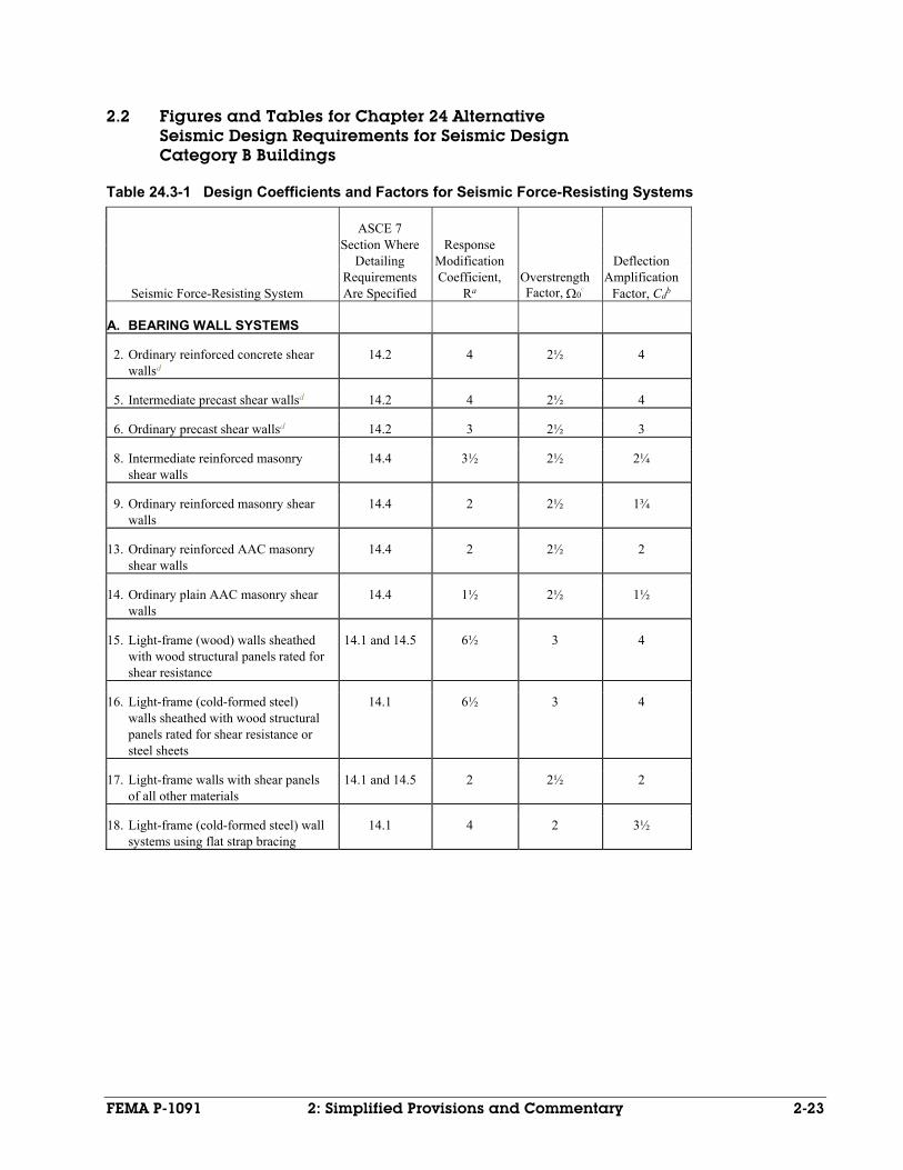
FEMA P-1091 2: Simplified Provisions and Commentary 2-23
2.2 Figures and Tables for Chapter 24 Alternative Seismic Design Requirements for Seismic Design Category B Buildings
Table 24.3-1 Design Coefficients and Factors for Seismic Force-Resisting Systems
Seismic Force-Resisting System
ASCE 7 Section Where
Detailing Requirements Are Specified
Response Modification Coefficient,
Ra Overstrength Factor, 0
c
Deflection Amplification
Factor, Cdb
A. BEARING WALL SYSTEMS
2. Ordinary reinforced concrete shear wallsd
14.2 4 2½ 4
5. Intermediate precast shear wallsd 14.2 4 2½ 4
6. Ordinary precast shear wallsd 14.2 3 2½ 3
8. Intermediate reinforced masonry shear walls
14.4 3½ 2½ 2¼
9. Ordinary reinforced masonry shear walls
14.4 2 2½ 1¾
13. Ordinary reinforced AAC masonry shear walls
14.4 2 2½ 2
14. Ordinary plain AAC masonry shear walls
14.4 1½ 2½ 1½
15. Light-frame (wood) walls sheathed with wood structural panels rated for shear resistance
14.1 and 14.5 6½ 3 4
16. Light-frame (cold-formed steel) walls sheathed with wood structural panels rated for shear resistance or steel sheets
14.1 6½ 3 4
17. Light-frame walls with shear panels of all other materials
14.1 and 14.5 2 2½ 2
18. Light-frame (cold-formed steel) wall systems using flat strap bracing
14.1 4 2 3½
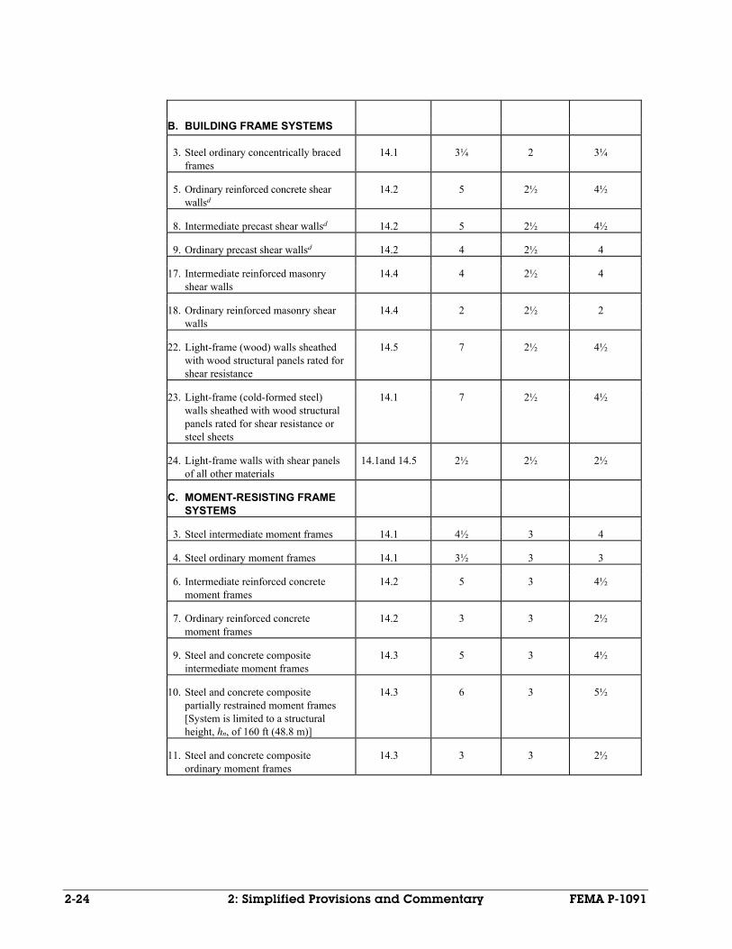
2-24 2: Simplified Provisions and Commentary FEMA P-1091
B. BUILDING FRAME SYSTEMS
3. Steel ordinary concentrically braced frames
14.1 3¼ 2 3¼
5. Ordinary reinforced concrete shear wallsd
14.2 5 2½ 4½
8. Intermediate precast shear wallsd 14.2 5 2½ 4½
9. Ordinary precast shear wallsd 14.2 4 2½ 4
17. Intermediate reinforced masonry shear walls
14.4 4 2½ 4
18. Ordinary reinforced masonry shear walls
14.4 2 2½ 2
22. Light-frame (wood) walls sheathed with wood structural panels rated for shear resistance
14.5 7 2½ 4½
23. Light-frame (cold-formed steel) walls sheathed with wood structural panels rated for shear resistance or steel sheets
14.1 7 2½ 4½
24. Light-frame walls with shear panels of all other materials
14.1and 14.5 2½ 2½ 2½
C. MOMENT-RESISTING FRAME SYSTEMS
3. Steel intermediate moment frames 14.1 4½ 3 4
4. Steel ordinary moment frames 14.1 3½ 3 3
6. Intermediate reinforced concrete moment frames
14.2 5 3 4½
7. Ordinary reinforced concrete moment frames
14.2 3 3 2½
9. Steel and concrete composite intermediate moment frames
14.3 5 3 4½
10. Steel and concrete composite partially restrained moment frames
[System is limited to a structural height, hn, of 160 ft (48.8 m)]
14.3 6 3 5½
11. Steel and concrete composite ordinary moment frames
14.3 3 3 2½
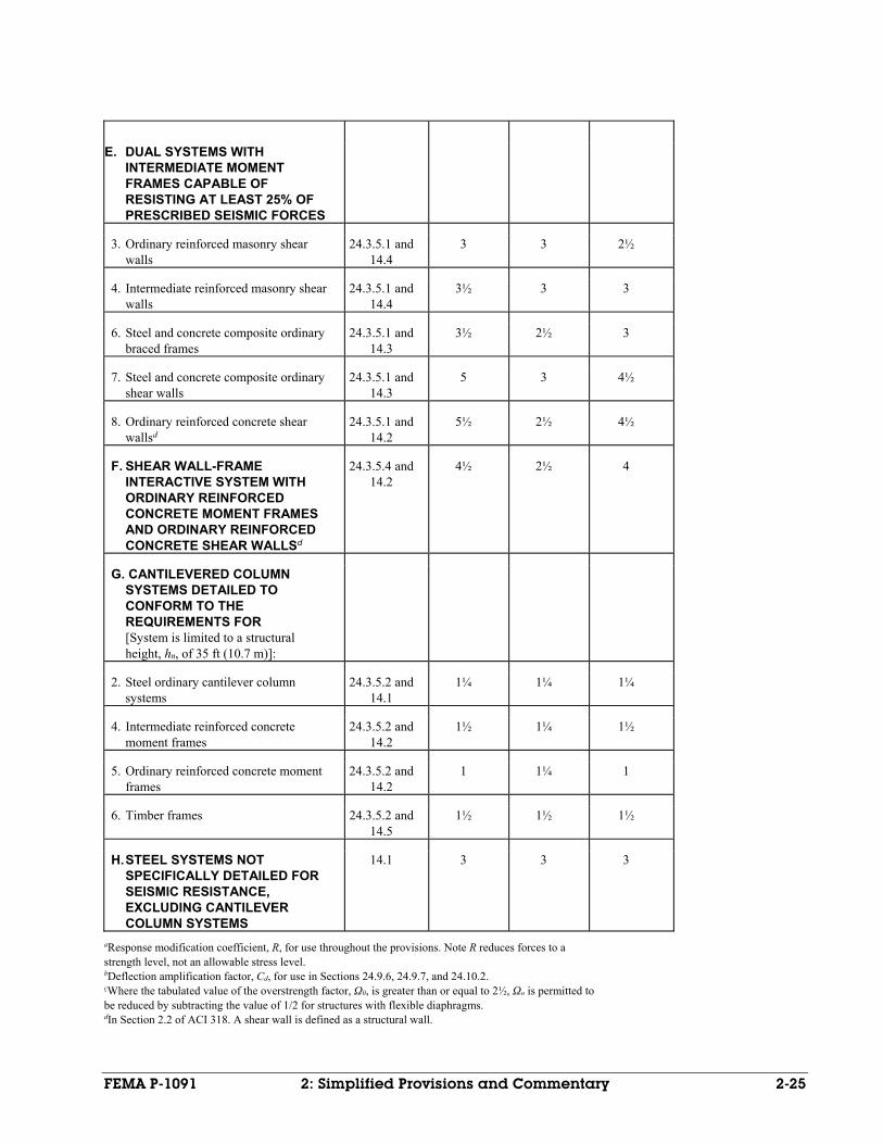
FEMA P-1091 2: Simplified Provisions and Commentary 2-25
E. DUAL SYSTEMS WITH INTERMEDIATE MOMENT FRAMES CAPABLE OF RESISTING AT LEAST 25% OF PRESCRIBED SEISMIC FORCES
3. Ordinary reinforced masonry shear walls
24.3.5.1 and 14.4
3 3 2½
4. Intermediate reinforced masonry shear walls
24.3.5.1 and 14.4
3½ 3 3
6. Steel and concrete composite ordinary braced frames
24.3.5.1 and 14.3
3½ 2½ 3
7. Steel and concrete composite ordinary shear walls
24.3.5.1 and 14.3
5 3 4½
8. Ordinary reinforced concrete shear wallsd
24.3.5.1 and 14.2
5½ 2½ 4½
F. SHEAR WALL-FRAME INTERACTIVE SYSTEM WITH ORDINARY REINFORCED CONCRETE MOMENT FRAMES AND ORDINARY REINFORCED CONCRETE SHEAR WALLSd
24.3.5.4 and 14.2
4½ 2½ 4
G. CANTILEVERED COLUMN SYSTEMS DETAILED TO CONFORM TO THE REQUIREMENTS FOR [System is limited to a structural height, hn, of 35 ft (10.7 m)]:
2. Steel ordinary cantilever column systems
24.3.5.2 and 14.1
1¼ 1¼ 1¼
4. Intermediate reinforced concrete moment frames
24.3.5.2 and 14.2
1½ 1¼ 1½
5. Ordinary reinforced concrete moment frames
24.3.5.2 and 14.2
1 1¼ 1
6. Timber frames 24.3.5.2 and 14.5
1½ 1½ 1½
H. STEEL SYSTEMS NOT SPECIFICALLY DETAILED FOR SEISMIC RESISTANCE, EXCLUDING CANTILEVER COLUMN SYSTEMS
14.1 3 3 3
aResponse modification coefficient, R, for use throughout the provisions. Note R reduces forces to a strength level, not an allowable stress level. bDeflection amplification factor, Cd, for use in Sections 24.9.6, 24.9.7, and 24.10.2. cWhere the tabulated value of the overstrength factor, Ω0, is greater than or equal to 2½, Ωo is permitted to be reduced by subtracting the value of 1/2 for structures with flexible diaphragms. dIn Section 2.2 of ACI 318. A shear wall is defined as a structural wall.
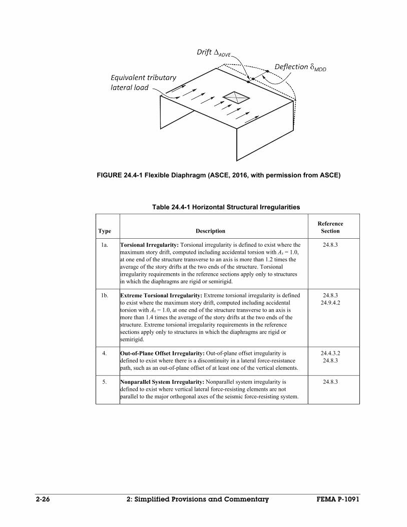
2-26 2: Simplified Provisions and Commentary FEMA P-1091
FIGURE 24.4-1 Flexible Diaphragm (ASCE, 2016, with permission from ASCE)
Table 24.4-1 Horizontal Structural Irregularities
Type
Description
Reference Section
1a. Torsional Irregularity: Torsional irregularity is defined to exist where the maximum story drift, computed including accidental torsion with Ax = 1.0, at one end of the structure transverse to an axis is more than 1.2 times the average of the story drifts at the two ends of the structure. Torsional irregularity requirements in the reference sections apply only to structures in which the diaphragms are rigid or semirigid.
24.8.3
1b. Extreme Torsional Irregularity: Extreme torsional irregularity is defined to exist where the maximum story drift, computed including accidental torsion with Ax = 1.0, at one end of the structure transverse to an axis is more than 1.4 times the average of the story drifts at the two ends of the structure. Extreme torsional irregularity requirements in the reference sections apply only to structures in which the diaphragms are rigid or semirigid.
24.8.3 24.9.4.2
4. Out-of-Plane Offset Irregularity: Out-of-plane offset irregularity is defined to exist where there is a discontinuity in a lateral force-resistance path, such as an out-of-plane offset of at least one of the vertical elements.
24.4.3.2 24.8.3
5. Nonparallel System Irregularity: Nonparallel system irregularity is defined to exist where vertical lateral force-resisting elements are not parallel to the major orthogonal axes of the seismic force-resisting system.
24.8.3
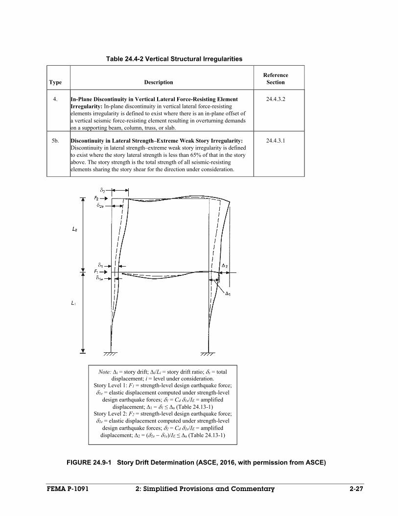
FEMA P-1091 2: Simplified Provisions and Commentary 2-27
Table 24.4-2 Vertical Structural Irregularities
Type
Description
Reference Section
4. In-Plane Discontinuity in Vertical Lateral Force-Resisting Element Irregularity: In-plane discontinuity in vertical lateral force-resisting elements irregularity is defined to exist where there is an in-plane offset of a vertical seismic force-resisting element resulting in overturning demands on a supporting beam, column, truss, or slab.
24.4.3.2
5b. Discontinuity in Lateral Strength–Extreme Weak Story Irregularity: Discontinuity in lateral strength–extreme weak story irregularity is defined to exist where the story lateral strength is less than 65% of that in the story above. The story strength is the total strength of all seismic-resisting elements sharing the story shear for the direction under consideration.
24.4.3.1
FIGURE 24.9-1 Story Drift Determination (ASCE, 2016, with permission from ASCE)
Note: i = story drift; i/Li = story drift ratio; x = total displacement; i = level under consideration.
Story Level 1: F1 = strength-level design earthquake force; 1e = elastic displacement computed under strength-level
design earthquake forces;1 = Cd 1e/IE = amplified displacement; 1 = 1 ≤ a (Table 24.13-1)
Story Level 2: F2 = strength-level design earthquake force; 2e = elastic displacement computed under strength-level
design earthquake forces;2 = Cd 2e/IE = amplified displacement; 2 = (2e1e)/IE ≤ a (Table 24.13-1)
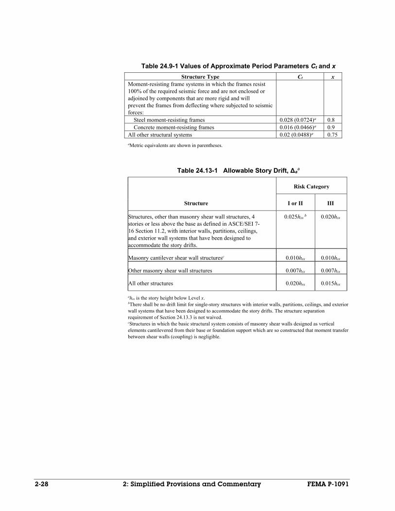
2-28 2: Simplified Provisions and Commentary FEMA P-1091
Table 24.9-1 Values of Approximate Period Parameters Ct and x
Structure Type Ct x Moment-resisting frame systems in which the frames resist 100% of the required seismic force and are not enclosed or adjoined by components that are more rigid and will prevent the frames from deflecting where subjected to seismic forces:
Steel moment-resisting frames 0.028 (0.0724)a 0.8 Concrete moment-resisting frames 0.016 (0.0466)a 0.9 All other structural systems 0.02 (0.0488)a 0.75
aMetric equivalents are shown in parentheses.
Table 24.13-1 Allowable Story Drift, Δaa
Structure
Risk Category
I or II III
Structures, other than masonry shear wall structures, 4 stories or less above the base as defined in ASCE/SEI 7-16 Section 11.2, with interior walls, partitions, ceilings, and exterior wall systems that have been designed to accommodate the story drifts.
0.025hsx b 0.020hsx
Masonry cantilever shear wall structuresc 0.010hsx 0.010hsx
Other masonry shear wall structures 0.007hsx 0.007hsx
All other structures 0.020hsx 0.015hsx
ahsx is the story height below Level x. bThere shall be no drift limit for single-story structures with interior walls, partitions, ceilings, and exterior wall systems that have been designed to accommodate the story drifts. The structure separation requirement of Section 24.13.3 is not waived. cStructures in which the basic structural system consists of masonry shear walls designed as vertical elements cantilevered from their base or foundation support which are so constructed that moment transfer between shear walls (coupling) is negligible.
FEMA P-1091 2: Simplified Provisions and Commentary 2-29
2.3 Commentary to Chapter 24 Alternative Seismic Design Requirements for Seismic Design Category B Buildings
C24.1 GENERAL
In recent years, engineers and building officials have become concerned that the seismic design requirements for Seismic Design Category B (SDC B) are complex and are difficult to implement because SDC B requirements could not be easily separated from the many other seismic design requirements that are not applicable to SDC B. Additionally, a systematic examination of SDC B design requirements was warranted, because some of the existing ASCE/SEI 7-16 Chapter 12 and Chapter 13 requirements may be unnecessary for the design of buildings at sites with moderate seismicity since the requirements have only a minimal influence on design.
In accordance with ASCE/SEI 7-16 Section 11.1.4, the alternative seismic design procedure presented in this chapter may be used for the structural systems and nonstructural components of buildings assigned to SDC B. This chapter is equivalent to the procedures described in ASCE/SEI 7-16 Chapters 12 and 13, but differs in two ways. First, the text and requirements presented in this chapter are substantially simpler and shorter, because the chapter has been editorially simplified to only include the requirements that apply in SDC B. Second, some of the seismic design requirements have been eliminated or simplified based on technical study. These technical simplifications apply to seismic design requirements which are applicable in SDC B, in accordance with ASCE/SEI 7-16 Chapters 12 and 13, but do not have significant influence on the resulting design or seismic performance. As described in more detail below, the implications of removing or simplifying seismic design requirements was carefully evaluated through design studies and nonlinear structural analyses. The commentary that follows describes the important differences between Chapter 24 and the seismic design requirements of ASCE/SEI 7-16 Chapter 12 and 13.
The provisions of Chapter 24 are required to be followed in their entirety without exception; if a designer wants to use any provisions in ASCE/SEI 7-16 Chapters 12 or 13 that are not included in this chapter, then the design must comply with all of the provisions of ASCE/SEI 7-16 Chapters 12 and 13 for SDC B structures.
Nonbuilding structures (ASCE/SEI 7-16 Chapter 15), seismically isolated structures (ASCE/SEI 7-16 Chapter 17), and structures with damping systems (ASCE/SEI 7-16 Chapter 18) are not permitted to be designed using the alternative procedures of Chapter 24.
An abridged version of the list of symbols in ASCE/SEI 7-16 Section 11.3 that apply to the seismic requirements of Chapter 24 has been included in this section for convenience.
C24.2 STRUCTURAL DESIGN BASIS
The requirements of this section closely follow those of ASCE/SEI 7-16 Section 12.1. The only modifications in this section are editorial simplifications, in which requirements have been eliminated when not applicable to SDC B buildings. In particular, a small change has been made in the design strength calculation for connections. In SDC B, all connections must be designed for 5% of the weight of the smaller portion of the structure. There is no need to calculate 0.133 times SDS, as required in Chapter 12, because the 5% limiting value will always govern designs in SDC B.
2-30 2: Simplified Provisions and Commentary FEMA P-1091
C24.3 STRUCTURAL SYSTEM SELECTION
The requirements of this section closely follow those of ASCE/SEI 7-16 Section 12.2. The only modifications in this section are editorial simplifications, in which requirements have been eliminated when not applicable to SDC B buildings. For example, numerous requirements found in Section 12.2, e.g. the requirements for Steel Intermediate Moment Frames in SDC D, have been eliminated because they are not applicable to SDC B buildings.
Additionally, the Table of Design Coefficients and Factors for Seismic Force-Resisting Systems (Table 24.3-1) has been substantially editorially simplified. Structural systems not commonly used in SDC B have been removed, including all “special” systems, which are used primarily in the higher SDCs. When rows were deleted from the Table of Design Coefficients and Factors for Seismic Force-Resisting Systems (Table 24.3-1), the numbering of the rows was intentionally kept unchanged and identical to the numbering used in Table 12.2-1. In addition, the columns relating to Structural System Limitations have been removed because all systems in the table are allowable in SDC B. The few remaining systems that have height limits imposed in SDC B have the height limits listed directly in the table, rather than in a separate column.
Another difference is that the provisions for alternate structural systems in Section 12.2.1.1 are not included in this simplified chapter, both because these alternate systems are not commonly used in SDC B and based on the level of rigor required to demonstrate compliance of such systems, the simplified provisions of this chapter are not appropriate. Alternate systems must be designed using the provisions of Chapter 12.
C24.4 DIAPHRAGM FLEXIBILITY AND CONFIGURATION IRREGULARITIES
The requirements of this section closely follow those of ASCE/SEI 7-16 Section 12.3. The only modifications in this section are editorial simplifications, in which requirements have been eliminated when not applicable to SDC B buildings. The tables defining Horizontal Structural Irregularities and Vertical Structural Irregularities (Tables 24.4-1 and 24.2-2) have been simplified to only include the irregularities that affect the design procedures in SDC B. Other irregularities, while they may be present, do not affect the design requirements and have been eliminated from the table. The numbering of the irregularities in Table 24.4-1 and Table 24.4-2 was intentionally kept identical to those of Tables 12.3-1 and 12.3-2. The irregularities of Tables 12.3-1 and 12.3-2 omitted from the Chapter 24 tables are horizontal irregularities Type 2 and 3, and vertical irregularities Type 1a, 1b, 2, 3, and 5a. These irregularities were omitted because they do not apply to SDC B.
C24.5 SEISMIC LOAD EFFECTS AND COMBINATIONS
The equations for seismic load effects and load combinations in the alternative design procedure are consistent with those for the general procedure of ASCE/SEI 7-16 Chapter 12, with the one notable exception being that the requirement for including the vertical seismic load effect has been removed. Accordingly, Ev is taken as zero in the Section 24.5 requirements and the Ev = 0.2SDSD term in the design load combinations has been removed.
The elimination of the vertical load effect requirement in SDC B was supported by design studies. These studies indicated that, due to the small SDS values in SDC B and, the small associated increase in design dead loads due to vertical seismic effects, there is no meaningful difference in member sizes and detailing if the vertical seismic load is considered in SDC B. Note that in the general Chapter 12 requirement, Ev may already be taken as zero when SDS < 0.125g, so this change
FEMA P-1091 2: Simplified Provisions and Commentary 2-31
simply expands the range of SDS values for which Ev may be zero up to SDS < 0.33g.
Additionally, the redundancy factor, ρ, has been removed from the load combinations because this factor is always equal to unity for SDC B buildings.
The final simplification in Section 24.5 is that the seismic load effect including the overstrength factor, Em, must be computed using Equation 24.5-2 and the exception has been removed. If a designer wants to use the more complex method of computing the maximum force that can be developed in the element, then Chapter 24 cannot be used and the general procedures of Chapters 12 and 13 must be used.
C24.6 DIRECTION OF LOADING
The requirements of this section closely follow those of ASCE/SEI 7-16 Section 12.5. Most of the text in Section 12.5 is related to SDC C and above, so the procedures in Section 24.6 have been shortened substantially.
C24.7 ANALYSIS PROCEDURE SELECTION
The structural analysis procedure must be either the Equivalent Lateral Force Analysis or the Modal Response Spectrum Analysis procedure. If a designer wants to use the more advanced Linear Response History Analysis procedure, then Chapter 24 cannot be used, and the building must be designed in accordance with the provisions in ASCE/SEI 7-16 Chapters 12 and 13.
C24.8 MODELING CRITERIA
The requirements of this section closely follow those of ASCE/SEI 7-16 Section 12.7 and only small editorial changes have been made.
C24.9 EQUIVALENT LATERAL FORCE PROCEDURE
In this section, the seismic design requirements have been simplified using both editorial and technical simplifications. The discussion below describes the technical differences between the general procedures of ASCE/SEI 7-16 Chapter 12 and the alternative procedures of this chapter.
C24.9.1 Seismic Base Shear
Determination of the seismic base shear is similar to the general procedure of ASCE/SEI 7-16 Chapter 12. The primary technical simplification is the elimination of the long-period region of the spectrum, i.e. for T > TL. In the Chapter 24 design procedure, longer period structures are to be designed following the same 1/T spectral shape used in the velocity sensitive region of the spectrum. The elimination of the long period region of the spectra is conservative, but it is not expected that it will affect many, if any, designs in SDC B.
Reductions associated with soil structure interaction are not permitted when using the alternative Chapter 24 design procedures.
C24.9.2 Period Determination
The approximate period, Ta, is computed according to Equation 24.9-5, and the other period determination equations from ASCE/SEI 7-16 Chapter 12 have been eliminated for simplicity. As in Chapter 12, the fundamental period of the structure may not exceed CuTa, but in these alternative procedures, for simplicity, Cu is taken as a constant value of 1.6. This 1.6 value is used because the Chapter 12 Cu values range only from 1.6 to 1.7 for all sites in SDC B. Use of the constant lower-bound 1.6 value is both simpler and slightly conservative, but will not result in any substantial change in the building design.
2-32 2: Simplified Provisions and Commentary FEMA P-1091
C24.9.4.2 Accidental Torsion
To simplify the process of computing member forces from seismic effects, the accidental torsional moment need not be included in design of SDC B buildings, unless the building has a Type 1b horizontal irregularity (Extreme Torsional Irregularity).
The decision to remove the accidental torsion requirement for most regular buildings is supported by rigorous analytical studies using nonlinear dynamic analysis of SDC B buildings designed both with and without use of the accidental torsion requirements. These analytical studies showed that the collapse resistance of buildings was not significantly altered if the accidental torsion requirements were eliminated in the design, for buildings with a torsional irregularity ratio of up to 1.4 (which is the torsional irregularity ratio corresponding to Type 1b horizontal irregularity). For structures with extreme torsional irregularities, the additional strength resulting from the use of the accidental torsion design requirements becomes critical for maintaining sufficient building collapse resistance. The details of this study, including the detailed design information for the 240 buildings analyzed, are available in DeBock et al. (2014).
C24.10 MODAL RESPONSE SPECTRUM ANALYSIS
The requirements of this section closely follow those of ASCE/SEI 7-16 Section 12.9 and only small changes have been made. The requirement to include a sufficient number of modes to obtain 100 percent mass participation was removed, and replaced by the exception in Section 12.9.1.1 allowing 90 percent mass participation, which is deemed appropriate for SDC B. The section on Scaling of Drifts was removed for editorial reasons because it does not apply to SDC B. Also, for simplicity, reductions associated with soil structure interaction are not permitted when using these Chapter 24 alternative procedures, and the associated guidelines were removed from the simplified procedure.
C24.11 DIAPHRAGMS, CHORDS AND COLLECTORS
The requirements of this section closely follow those of ASCE/SEI 7-16 Section 12.10, and only minor editorial simplifications were made to remove requirements not applicable to SDC B buildings. The alternate design procedure for diaphragms, chords, and collectors in Section 12.10.3 was removed since it is not required for precast diaphragms in SDC B, and it is not expected to be commonly used as a voluntary alternate for other diaphragm systems in SDC B. If a designer wants to use that procedure, the building must be designed in accordance with Chapters 12 and 13.
C24.12 STRUCTURAL WALLS AND THEIR ANCHORAGE
The requirements of this section closely follow those of ASCE/SEI 7-16 Section 12.11, and only minor editorial simplifications were made to remove requirements not applicable to SDC B buildings
C24.13 DRIFT AND DEFORMATION
The requirements of this section closely follow those of ASCE/SEI 7-16 Section 12.12. The only modifications in this section are editorial simplifications, in which requirements have been eliminated when not applicable to SDC B buildings.
One specific editorial simplification is that the table for Allowable Story Drifts (Table 24.13-1) has been simplified to only provide the displacement limits for Risk Categories I, II and III, since it is not possible for Risk Category IV to occur in SDC B.
FEMA P-1091 2: Simplified Provisions and Commentary 2-33
C24.14 FOUNDATION DESIGN
The requirements of this section closely follow those of ASCE/SEI 7-16 Section 12.13. The only modifications in this section are editorial simplifications, in which requirements have been eliminated when not applicable to SDC B buildings.
In addition, the provisions for Strength Design for Foundations Geotechnical Capacity in Section 12.13.5 were removed for simplicity. If a designer wants to use these provisions, then ASCE/SEI 7-16 Chapters 12 and 13 must be used.
C24.15 SEISMIC DESIGN REQUIREMENTS FOR EGRESS STAIRWAYS AND PARAPETS
Section 24.15 includes all of the seismic design criteria for nonstructural components in Seismic Design Category B. In the general procedures of ASCE/SEI 7-16 Chapter 13, all mechanical and electrical components, and most architectural components, in SDC B are exempt. Accordingly, Section 24.15 seismic design requirements are oriented exclusively toward egress stairways and parapets.
Additional editorial and technical simplifications have been made to the seismic design requirements for nonstructural components. The discussion below describes the technical differences between the general procedures of ASCE/SEI 7-16 Chapter 13 and the alternative procedures of Section 24.15.
C24.15.2 General Design Requirements
The alternative procedure does not permit manufacturer’s certification that a component is qualified by testing or experience data; this simplification was made because it is expected that the use of this approach would be rare in SDC B. If it is desirable to use one of these removed approaches in design of nonstructural components, Chapter 24 should not be used and the general provisions of ASCE/SEI 7-16 Chapters 12 and 13 should be followed.
Additionally, the requirements related to flexibility and consequential damage were removed in the alternative procedures because they are not required for the design of egress stairways or parapets.
C24.15.3 Seismic Design Force
The alternative seismic design requirements do not permit accelerations to be determined by the modal analysis procedures, as this approach is not commonly used in SDC B.
C24.15.4 Design of Egress Stairways for Seismic Relative Displacements
Only egress stairways are required to be designed for seismic relative displacements because design for seismic relative displacements does not affect the design of parapets.

FEMA P-1091 3: Recommendations for Future Improvement 3-1
Chapter 3
Recommendations for Future Improvement
3.1 Introduction
This chapter provides recommendations for future improvements to Chapter
24. These recommendations are based primarily on the feedback from
engineering firms with design experience in Seismic Design Category B
regions that were commissioned to perform trial designs using the simplified
provisions (BSSC, 2015). The improvements recommended herein, and
other changes, could be considered during the 2015-2020 update cycle of the
NEHRP Provisions.
Overall, the trial design engineers found Chapter 24 easy to use. They
appreciated the consistency with ASCE/SEI 7 Chapter 12, calling the new
Chapter 24 provisions “familiar.” They stated that Chapter 24 would be
readily useable by engineers that design buildings in Seismic Design
Category B, and also by engineers that design buildings in multiple Seismic
Design Categories, because it would be easy to go back and forth between
Chapter 24 and ASCE/SEI 7 Chapter 12.
Although the simplified provisions were viewed favorably by the trial design
engineers, several recommendations for additional simplifications to Chapter
24 were suggested. These recommendations can be grouped into the
following broad categories:
Structural systems eligible for the procedure (Table 24.3-1)
Analysis procedures and requirements
Configuration requirements
Foundations
Recommendations for which there appeared to be consensus among the trial
design engineers, and that were considered reasonable for inclusion in future
versions of Chapter 24, are provided below.
3-2 3: Recommendations for Future Improvement FEMA P-1091
3.2 Recommendations
3.2.1 Structural Systems Included in the Procedure
Most of the trial design engineers recommended additional simplifications to
Table 24.3-1 to eliminate seismic force-resisting systems that are not
commonly used in Seismic Design Category B. Recommendations included
removing the following systems (Table 24.3-1 designation in parenthesis):
Steel and concrete composite systems (C9 and C10)
Dual systems (E3, E4, E5, E7, and E8)
Shear wall-frame interaction systems (F)
Other systems were also recommended for deletion, including all
“intermediate” systems and all steel systems other than R = 3 systems.
However, it is recommended that these systems remain included in Chapter
24 to provide more flexibility for designers using the provisions.
3.2.2 Analysis Procedures and Requirements
3.2.2.1 Dynamic Analysis
Several trial design engineers recommended further simplification of
Chapter 24 by removing the modal response spectrum analysis procedure
(Section 24.10). This was recommended for the following reasons:
Dynamic analysis is not commonly used in Seismic Design Category B,
especially among the intended users of Chapter 24 provisions. Designers
who typically perform dynamic analyses are likely to be comfortable
using ASCE/SEI 7-16 Chapter 12.
For structures in which dynamic analysis may be beneficial (e.g.,
buildings that are taller, or have higher mode effects), wind is likely to
govern the lateral design, reducing the advantages of the modal response
spectrum analysis procedure.
The new requirement in ASCE/SEI 7-16 to scale forces determined using
modal analysis to 100 percent of the equivalent lateral force (ELF) base
shear (instead of 85 percent used in ASCE/SEI 7-10) further reduces the
potential benefits of the modal response spectrum analysis procedure.
3.2.2.2 Two-Stage Analysis
Several trial design engineers recommended removing the two-stage analysis
procedures from Chapter 24. Similar to dynamic analysis, this procedure is
not commonly used in Seismic Design Category B, and those who use the
FEMA P-1091 3: Recommendations for Future Improvement 3-3
procedure are expected to be comfortable using ASCE/SEI 7-16 Chapter 12
for analysis and design.
However, one trial design engineer recommended keeping this procedure in
Chapter 24, noting that it is a useful procedure for low-rise, mixed-use type
podium structures even in Seismic Design Category B. Further review of
this procedure is recommended.
3.2.2.3 Period Determination
Trial design engineers recommended adding the alternate period
determination formulae (ASCE/SEI 7-16 Equations 12.8-8 through 12.8-10)
back into Chapter 24, and recommended keeping the Cu factor in Chapter 24
the same as defined in ASCE/SEI 7-16 Chapter 12. In the current version of
Chapter 24, these simplifications were judged to be unnecessary, and would
remove provisions that could be beneficial to designers in Seismic Design
Category B. It was noted that when designers use commercial software or
in-house analytical tools, it is helpful to have Chapter 24 provisions
consistent with the ASCE/SEI 7-16 Chapter 12 on which these analysis tools
are based, in order to avoid the need for customization of software for use
with Chapter 24.
3.2.3 Configuration Requirements
Based on information from the trial designs, simplification of the accidental
torsion requirements is potentially the most significant simplification in
Chapter 24, but the current approach is ineffective because the user is
required to include accidental torsion in the preliminary analysis to determine
whether or not the building has a plan torsional irregularity, and to, therefore,
determine if accidental torsion can be excluded in the design process.
Accordingly, in the current approach, the user does not get much benefit
from this simplification, and the trial design engineers strongly suggested
additional simplification related to checking for torsional irregularity.
The quantitative impacts of the accidental torsion simplification were also
tested in the trial designs. Even though two of the four trial buildings had a
torsional irregularity ratio of nearly 1.4 (on the verge of an extreme plan
torsional irregularity), removal of the torsion check only changed component
design forces by about 2-14% in the cases tested. Based on the trial design
results, and associated discussions among the trial design engineers, the
consensus was that the removal of accidental torsion did not have a
significant impact on design in Seismic Design Category B.
3-4 3: Recommendations for Future Improvement FEMA P-1091
3.2.4 Foundations
It is recommended that the foundation load-deformation provisions (Section
24.14.3) be removed, and the scope of Chapter 24 be limited to fixed-based
analysis assumptions. A fixed-base assumption is the more common
approach in Seismic Design Category B, and designers familiar with flexible-
base foundation design are expected to be comfortable using ASCE/SEI 7-16
Chapter 12 for analysis and design.
FEMA P-1091 A: Simplification of Seismic Code Provisions A-1
Appendix A
Simplification of Seismic Code Provisions
This appendix is a reprint, and limited update, of a white paper authored by
W. Holmes and published by the Building Seismic Safety Council (BSSC)
under the BSSC Simplified Seismic Design Procedures Development
Program (Holmes, 2015).
A.1 Introduction
Over the past several decades, the seismic design procedures and provisions
in U.S national model codes and standards have continuously been refined
and been made more comprehensive to cover more building types and sizes,
to be efficient for design of buildings located in regions with a wide range of
seismicity, to accommodate an ever-expanding state-of-the-art, and to
incorporate lessons learned from damaging earthquakes. As a result, the
design provisions have grown in number and complexity. In addition,
national standards such as ASCE/SEI 7-05, Minimum Design Loads for
Buildings and Other Structures (ASCE, 2005) reference extensive material
standards for various material design details, which also contribute to the
complexity of the design process.
Some engineers and building officials have articulated their concern that
current code provisions are difficult for them to understand and to correctly
implement, particularly for simple and small buildings that are expected to be
designed quickly and efficiently (Hess, 2009; Hamburger, 2010; Tong,
2017). These concerns are particularly troublesome if lack of understanding
or short-cuts lead to incomplete or incorrect designs of buildings that will
perform poorly in strong ground shaking or, on the other hand, of buildings
that are unreasonably over-designed as a compromise to avoid complex code
requirements. Although training is available in various forms for correct use
of seismic design provisions, only a minority of engineers take advantage of
these opportunities. Automation has also been suggested as a partial
solution, but in the U.S., many engineers are wary of such applications due to
potential misuse on the wide variety of materials and configurations used in
building construction here. In recognition of this dilemma, exploration of the
development of simplified design procedures was encouraged by FEMA and
A-2 A: Simplification of Seismic Code Provisions FEMA P-1091
a modest start was contained in the 2003 NEHRP Recommended Provisions
for Seismic Regulations for New Buildings and Other Structures (NEHRP
Provisions; FEMA, 2003) covering simple short and stiff structures.
Subsequently, the national load standard, ASCE/SEI 7-05 incorporated
similar simplified design provisions in Section 12.14. The initial
development effort was the result of a more comprehensive planning study
previously completed during the development of the 2000 NEHRP
Provisions (FEMA, 2000). The 2000 study concluded that simplification and
improved understanding of the code procedures could be accomplished in
several ways, including editing and clarifying the current provisions,
reducing prescription and emphasizing performance-based design, reducing
complexity by increasing conservatism, or developing structure-specific
provisions parallel to the main design standard that might not even follow the
current general procedures but would yield equivalent performance.
The issues, interests, and viewpoints related to simplification of seismic
design are multiple. They include the public need for provision of adequate
seismic safety, highly variable designer interest and motivation (particularly
in regions of infrequent seismic activity), the economic interests of various
material industries, the inherent complexity of the design process due to
variation of design ground motion by geographic area and site soil
conditions, the nonlinear dynamic response of structures to shaking, and the
rich variety of building systems and styles used in the United States. The
very process of building code development encourages consideration of
additional aspects and nuances of structural seismic response, which tends to
continually add provisions, and seldom eliminates or simplifies the
procedures. Some are concerned that seismic code changes are occurring
faster than they can be absorbed, that added complexity may not assure safer
buildings, and that the costs to design professionals and owners are
excessive. Although many different approaches have already been proposed
or explored in various attempts to meet the largely dispersed interests in
simpler and more efficient seismic design methods, it is widely recognized
that there is no practical overall simplification to the seismic design
procedures as a whole. The only existing simplified design procedures in
ASCE/SEI 7 (Section 12.14) were developed in 2003 as a conservative sub-
set of the existing standard design requirements, applicable only to a narrow
type of low rise buildings, primarily because there was concern about
proving code equivalency for design provisions that used completely
different procedures (e.g., displacement based design).
Since then, the recently developed procedures for qualifying new structural
systems for incorporation in the building code as described in FEMA P-695,
FEMA P-1091 A: Simplification of Seismic Code Provisions A-3
Quantification of Building Seismic Performance Factors (FEMA, 2009), also
can be used to demonstrate equivalency with code objectives for alternative
design methodologies with less prescription or that are not based on
traditional force-based design concepts. This capability was not available
during the development cycles of the 2000 or 2003 NEHRP Provisions,
when the initial simplified design procedures were studied.
It also must be noted that a considerable portion of perceived complexity in
overall seismic code provisions stems from the material-specific detailing
requirements needed to provide the ductility and toughness assumed in the
main body of the code. These detailing requirements are typically provided
by expert committees organized and sponsored by various groups that
promulgate material-specific design standards. There has been little effort to
simplify these provisions, other than industry sponsored handbooks and
tables intended to clarify requirements and pre-calculate parameters.
A.2 New Studies Began in 2009
Beginning in 2009, FEMA, through the National Institute of Building
Sciences’ Building Seismic Safety Council (BSSC), initiated new studies of
seismic code simplifications, intended to be more comprehensive than
previous studies. The study (the Simplified Seismic Design Procedures
Project) was intended primarily to generate simplifications to the 2015
NEHRP Recommended Seismic Provisions for New Buildings and Other
Structures, FEMA P-1050-1 (FEMA, 2015a), but also to test the viability of
various methods of simplification, including use of stand-alone provisions
for individual building types and use of FEMA P-695 to prove equivalency.
The study included review of input on the subject received by FEMA since
2000, articles and papers discussing simplified design, new input from
various regions of the country obtained by the project team, and
consideration of various guidelines currently available to assist engineers
with seismic design.
Various options for simplification were identified. In general, the project
focused on simplification of provisions in the main body of the code
contained in the NEHRP Provisions, particularly considering the capabilities
of FEMA P-695. Obvious opportunities to simplify, or eliminate, material-
specific detailing requirements were also considered. The background study,
identification of options, and final recommendations were documented in a
report, Development of Simplified Seismic Design Procedures, Framework
Report (FEMA, 2010), available on the BSSC Portal.
A-4 A: Simplification of Seismic Code Provisions FEMA P-1091
A.3 Framework Report
The Framework Report described many options for simplification of seismic
design provisions. Complete overhaul of the U.S seismic design provisions,
suggested by some, was not an option because: (1) such a massive effort is
completely beyond the scope of this project; and (2) it is not clear that such
an effort would result in simplification, considering that the state of the art of
seismic design is inherently complicated and the code must cover many
building types. Similarly, a major editorial rewrite to improve clarity was
not an option, primarily because just such an effort was completed for the
2003 NEHRP Provisions (FEMA, 2003). Therefore, realistic options that
were identified were generally focused on narrowly defined buildings types,
or groups of buildings with similar seismic characteristics, that could
potentially be designed for more specific—and simpler—requirements than
the base code. The very large number of structural materials and systems
used in the U.S., coupled with somewhat unlimited configurations, results in
a variation in building stock covered by the seismic code that is perhaps the
largest in the world. This variation somewhat limits the applicability of
simplifications with a narrow focus. The primary options included in the
Framework Report are discussed below.
A.3.1 Further Simplification of ASCE/SEI 7-10, Section 12.14
ASCE/SEI 7 includes Section 12.14, Simplified Alternative Structural Design
Criteria for Simple Bearing Wall or Building Frame Systems, which is the
result of previous developmental work by BSSC. This section allowed a
simplified version of the equivalent static force analysis for seismic load
effects along with a somewhat simpler statement of required strengths for
selected components. It is applicable to buildings up to three stories tall and
regular configuration, as long as the seismic-force-resisting system (SFRS) is
composed of bearing walls or braced frames. One of the premises is that
such buildings do not require the computation of lateral drift, which is a
substantial simplification.
The section is useful for qualified buildings with flexible diaphragms, but it
was widely criticized as not being particularly useful for qualified buildings
with rigid diaphragms. The reason is that a check for sensitivity to horizontal
torsion is required for such buildings (ASCE/SEI 7-05 Equations 12.14-2A
and 12.14-2B). The check itself required computation of the stiffness of each
vertical element of the seismic force resisting system, and it was
algebraically complex, essentially negating other simplifications of the
procedure.
FEMA P-1091 A: Simplification of Seismic Code Provisions A-5
Suggestions were made for simplifying this portion of Section 12.14 and,
given the investment of effort to date in development, plus the generally
favorable acceptance of the remainder of the section, an attempt to overcome
this shortcoming appeared to be justified.
A.3.2 Development of Stand-Alone Design Provisions for Low and Moderate Seismic Regions (Seismic Design Category B and C)
The concept of reducing complexity and increasing clarity using stand-alone
and targeted design provisions for buildings with certain characteristics has
been suggested before, but never tested.
Developing stand-alone seismic design requirements for Seismic Design
Category (SDC) B and C buildings was an option for consideration. Seismic
Design Categories B and C represent low-to-moderate seismic hazard areas
that cover a large portion of the United States, and stand-alone provisions
would be useful to many structural engineers. However, the seismic design
requirements for SDC B and SDC C differ on many key seismic design
issues. Physical separation of the provisions would make them easier to
follow; however, simplification would probably imply identifying
commonality in requirements. This would result in an increase in the design
requirements for SDC B, reductions in requirements for SDC C, or would
demand development of completely new provisions. These options appeared
to present difficult issues that would require extensive analysis in accordance
with FEMA P-695, to resolve.
A.3.3 Development of Stand-Alone Design Provisions for Low Seismic Regions (for Seismic Design Category B)
This option consisted of development of specific seismic design requirements
for SDC B buildings. These requirements could be developed in a stand-
alone document or as a special section of the current seismic design
standards. For either approach, only the seismic design requirements for
SDC B would be included in the stand-alone document or special section,
and would be expected to be much shorter than provisions that must cover all
regions of seismicity. This option could be pursued by editorial and/or
technical changes to the seismic design requirements of ASCE/SEI 7-10,
Minimum Design Loads for Buildings and Other Structures (ASCE, 2010).
A.3.4 Development of Stand-Alone Design Provisions for Buildings with Rigid Walls and Flexible Diaphragms
Single-story buildings with rigid walls and flexible diaphragms (RWFD
buildings) are common throughout the United States, and are often used for
A-6 A: Simplification of Seismic Code Provisions FEMA P-1091
warehouse buildings and “big box” retail stores. These buildings have stiff
walls constructed of reinforced concrete or masonry, or braced frames of
structural steel, and relatively flexible diaphragms of bare metal deck or
wood structural panels. For typical large footprint RWFD buildings,
deformation and cyclic behavior of the flexible diaphragm dominates the
response to earthquake ground motions. Seismic provisions of building
codes used in the United States, including those of ASCE/SEI 7-10, are
developed based on seismic response dominated by deformation of the
vertical elements of the seismic force-resisting system. Engineers involved
in building code development have long suspected that the standard code
model for seismic provisions does not fit well for design of RWFD buildings.
The committee that studied code simplification for the 2000 NEHRP
Provisions Update Committee considered developing stand-alone seismic
provisions for RWFD building that would focus on the diaphragm response.
Simplification or clarification could occur because the design engineer would
only have to refer to the stand-alone provisions; in addition, stand-alone
provisions could more easily use a response model that was different from
the primary code (i.e., diaphragm rather than vertical elements). But separate
design provisions were not fully developed at that time, primarily because a
procedure for establishing equivalent performance to that intended by the
base code was not available. This hurdle has been overcome with the
availability of FEMA P-695.
A.3.5 Development of Stand-Alone Design Provisions for Wood-Frame Buildings
The vast majority of building construction in the United States utilizes wood
light framing—bearing, closure, and partition walls of repetitive studs
supporting floors and roofs framed with repetitive joists or trusses. The
walls, floors, and roofs act as shear panels with the wood structural panels
and gypsum wallboard providing the strength and stiffness for the shear
panel action. This structure type is so common for single family residences
that simplified, prescriptive rules have been available in codes for decades
that can be used without engineering design. In addition, the American
Wood Council (AWC) has developed the Wood Frame Construction Manual
for One- and Two-Family Dwellings (AWC, 2015) to address design and
construction issues for this building type. However, there are still many such
buildings that are designed directly from code provisions.
The shear panel systems develop substantial ductility, mostly through
inelastic action in and around the panel connectors. The fact that there are
many components in the system means that there are many boundaries across
FEMA P-1091 A: Simplification of Seismic Code Provisions A-7
which forces must be transferred, and design and detailing of these load paths
causes the bulk of design time and complexity. Providing details for transfer
of force across the many boundaries within the typical light-frame structure
is a painstaking and time-consuming task.
The availability of a stand-alone set of seismic provisions limited to wood
light-framed structures would be convenient for designers, but would
probably not be substantially simpler than the base code, and will not reduce
the complexities from providing load paths. Furthermore, proposed changes
to the base code to achieve further simplifications using FEMA P-695 would
require a very extensive set of archetypical designs because there are so
many actual configurations of wood frame structural systems exist.
A.3.6 Use of the Ratio of Bearing Walls to Floor Area as a Primary Design Requirement
Rules allocating the amount and location of walls for seismic design in a
concrete bearing wall building could be established using FEMA P-695, and
could be determined independently for each SDC. The specific limitation on
wall location would be determined consistent with the occupancy of the
building. For instance, wall locations for a residential structure would be
different from those for an office building. The archetype design space
would need to be selected based on building occupancy and the resulting
rules for wall placement consistent with the analysis results.
Rules-of-thumb consistent with this approach have been used in Chile, where
mid- to high-rise residential structures consist almost exclusively of concrete
bearing wall systems. Given the wall layout mandated by the various
occupancy types, the large amount of variation in U.S. building
configuration, and the amount of wall that would likely result (two to three
times greater that is currently used in the U.S.), this option was not
recommended for further investigation.
A.3.7 Reduce Material Detailing Requirements (to Achieve Ductility) with Use of Lower R Factors
The detailing requirements for systems with high R factors generally involve
design checks to avoid brittle limit states (e.g., tensile fracture of structural
steel or compressive crushing of concrete) and to avoid focusing the inelastic
demand in a small portion of the system (e.g., the “strong-column, weak-
beam” rule for special moment frames). Many of these detailing rules are
rooted in the concept of “capacity design,” in which the structure is
constrained by design to perform in certain desirable manners. These
detailing requirements can be very time consuming in engineering practice.
A-8 A: Simplification of Seismic Code Provisions FEMA P-1091
The NEHRP Provisions and ASCE/SEI 7-10 are written to exclude the most
brittle systems, generally those with the lower R factors, from use in higher
seismic design categories, generally in locations with the potential for very
large seismic ground motions. In some cases, the restrictions apply primarily
to tall structures whereas in others, the restrictions apply to all heights.
Suggestions to relax these restrictions by requiring higher loading (smaller R
factors) have been made in the past. Since the design procedures include a
reduction in the MCE ground motion as a part of the basic equation for an
equivalent design force, even an R of 1.0 implies acceptable structural
performance beyond the design loading assumptions. Some individuals
cognizant of this fact suggest a value of R equal to 2/3 as a safe alternative.
Given that the ground motions to be considered exhibit a significant
variability in key parameters, and that the capacity of a structure is not
known with certainty, a probabilistic approach is probably needed when
considering these marginal cases. The FEMA P-695 methodology would
provide guidance in this regard, but the amount of work required to perform
these analyses systematically for a wide category of structural systems would
be overwhelming. Therefore, this option was not recommended for further
study.
A.3.8 Options Studied
In 2010, the Project Management Committee, in consultation with a Project
Review Committee and FEMA, selected three options for study and
development, based on somewhat limited resources, the most needed subject
areas, and potential benefits. The results of these studies are described
below.
A.3.8.1 Further Simplification of ASCE/SEI 7-10, Section 12.14
The primary goal for this simplification was to eliminate the complex
torsional check for qualifying buildings with rigid diaphragms that was
described as part of the Framework Report. Considering that using flexible
diaphragm assumptions is a desirable design simplification, studies were
undertaken to determine what conditions would require rigid diaphragm
assumptions for the sub group of buildings that qualified for ASCE/SEI 7-10
Section 12.14. General use of flexible diaphragm assumptions in ASCE/SEI
7-10 Section 12.14 for all diaphragms would not only eliminate the need for
the torsional check, but also introduce additional simplification. Extensive
FEMA P-695 analyses were run on small structures with a variety of wall
and brace layouts to determine under what conditions the results of design
would diverge using assumptions for both flexible and rigid diaphragms.
The FEMA P-695 methodology yields an index related to probability of
FEMA P-1091 A: Simplification of Seismic Code Provisions A-9
collapse and, as long as the index for designs using flexible diaphragm
assumptions was equal to or better than design using rigid diaphragm
assumptions, flexible diaphragm assumptions were acceptable.
It was found that design in which the seismic forces are apportioned to the
vertical lateral force resisting elements as if the diaphragm was flexible was
acceptable under the following conditions:
For structures with two lines of resistance in a given direction, and the
distance between the two lines is at least 50% of the length of the
diaphragm perpendicular to the lines;
For structures with more than two lines of resistance in a given direction,
and the distance between the two most extreme lines or resistance is at
least 60% of the length of the diaphragm perpendicular to the lines;
Where two or more lines of resistance are closer together than one-half
the horizontal length of the longer of the two walls or braced frames, the
lines can be replaced by a single line at the centroid of the group for the
initial distribution of forces, and to distribute the resulting force to the
members of the group based on their relative stiffness.
The conditions outlined above are relatively easy to achieve in the structures
that qualify for design under ASCE/SEI 7-10 Section 12.14, so in most cases,
flexible diaphragm assumptions can be used, simplifying ASCE/SEI 7-10
Section 12.14 considerably.
A change based on this approach was proposed and adopted by the
Provisions Update Committee for the 2015 NEHRP Provisions, and adopted
into ASCE/SEI 7-16, Minimum Design Loads and Associated Criteria for
Buildings and Other Structures (ASCE, 2016).
A.3.8.2 Development of Stand-Alone Design Provisions for Low Seismic Regions (for Seismic Design Category B)
Seismic Design Category B (SDC B) structures are located in regions of very
low seismicity where maximum considered ground motion spectral
accelerations, as modified for local soil conditions are:
0.167 ≤ SDS < 0.33
where:
SDS = design spectral response acceleration for short periods,
and:
0.067 ≤ SD1 < 0.133
A-10 A: Simplification of Seismic Code Provisions FEMA P-1091
where:
SD1 = design spectral response acceleration for a period of 1.0 sec.
SDC B structures include all buildings in these areas except Risk Category
IV (essential occupancies). The area covered by the SDC B design criteria
applies to much of the densely populated east so a very large number of
buildings in the U.S. are covered by the SDC B design criteria. Seismic
design provisions for these buildings are minimal but design engineers must
still use all 80 pages of the seismic design provisions in ASCE/SEI 7, even
though most provisions are not applicable.
In this study, several concepts were used to minimize the provisions needed
to design SDC B buildings:
Editorial Deletions. All the provisions that do not apply to SDC B
buildings are simply removed. For example, there are nine pages of
provisions in ASCE/SEI 7 covering nonstructural components, but only
parapets and exit stairs are specified for protection in Seismic Design
Category B. The necessary provisions could thus be covered in about
one-third of a page.
Judgmental Deletions. Since SDC B provisions are to be specified as
an option to the use of the full code, regulations that are very rarely used
could be eliminated. If these regulations are needed for an unusual
building, the design engineer can resort to design by the full code. For
example, there are many structural systems listed in the so-called
“R-factor table”, (officially titled, “Design Coefficients and Factors for
Seismic Force-Resisting Systems”) that are never, or rarely, used in SDC
B. These are primarily archaic systems (e.g. Plain concrete shear walls)
and high ductility systems (e.g. Special moment frames of concrete or
steel), neither of which, according to several engineers familiar with
SDC B design, are used. This reduces the table of 83 systems to 36.
Technical Simplifications. The availability of FEMA P-695 allows
determination of equivalency for technical changes. For example,
FEMA P-695 was used to demonstrate that the use of accidental torsion
is not required unless the building has an Extreme Torsional Irregularity.
This study resulted in acceptance of a proposal to add a stand-alone chapter
in the 2015 NEHRP Provisions for design of SDC B buildings. The
simplified chapter consists of only 35 pages as an alternate to the full seismic
provisions spread over 11 chapters comprising 87 pages. Engineers
designing SDC B buildings will only need to refer to this chapter and the
associated material standards previously discussed.
FEMA P-1091 A: Simplification of Seismic Code Provisions A-11
To test the merit of the concept and the efficiency of the technical changes,
trial designs were commissioned to three engineering companies practicing
in SDC B regions. The buildings used in the trial designs had been
previously designed using the full code provisions. The structures
incorporated the following seismic systems:
1. a three-story steel moment frame (R = 3);
2. a four-story, light-framed wood shear wall (R = 6.5);
3. a four-story ordinary reinforced concrete wall (R = 4);
4. a six-story steel braced frame (R = 3).
The results of the trial design study are summarized as follows:
The resulting designs did not differ significantly from the original
designs previously completed using the full code.
The stand-alone format was viewed very favorably. Trial design
engineers suggested that such a format would both prevent omissions of
requirements and prevent confusion from mixing requirements from
different Seismic Design Categories. Design engineers uniformly
reported that they would use such provisions if they were code-approved.
Most of the engineers suggested additional judgmental deletions on the
basis that they are seldom used—provisions for spectral analysis,
foundation modeling, and two stage analyses.
The attempted simplification to eliminate accidental torsion was not seen
favorably. The analytical tests needed to eliminate the inclusion of
accidental torsion were seen to be equal to, or in some cases, more time
consuming than the original provision.
This particular test of the concept of stand-alone provisions for specific
building types or groups of buildings was found to be successful and useful.
However, to be incorporated into building codes commonly used in the U.S.,
the chapter must be adopted into ASCE-SEI 7. Such a change proposal was
made in 2014 and rejected, due to arguments that: (1) simplification of the
seismic code was not needed at all; and (2) parallel methods of design,
represented by a stand-alone chapter, created unwarranted ongoing risks of
inconsistent updating and a potential double standard. This result was
disappointing, but the stand-alone chapter is available in the 2015 NEHRP
Provisions as well in the final report, Report on the 2015 NEHRP Chapter 24
Stand-Alone Seismic Design Requirement for SDC B Buildings, (BSSC,
2015). However, it will be necessary for engineers wanting to use this
A-12 A: Simplification of Seismic Code Provisions FEMA P-1091
chapter to obtain approval from local building departments as to it
equivalency and acceptability.
A.3.8.3 Development of Stand-Alone Design Provisions for Buildings with Rigid Walls and Flexible Diaphragms
This study, in addition to developing improved design provisions for
buildings with rigid walls and flexible diaphragms (RWFD), was also a test
of the concept that design provisions narrowly directed at a single building
type could be simpler and provide designs that would more consistently meet
expected performance standards. The seismic response of this type of
structure is practically all in the displacement of the large and relatively
flexible diaphragms. However, the standardized design methods used in
current seismic codes for all buildings assume primary response occurs in
deformation of the vertically oriented lateral force-resisting elements (i.e.,
the moment frames, braced frames, or shear walls). A design approach for
this building type that was more technically correct, and that could be shown
to meet accepted code performance, had been sought for some time. Such an
approach would also meet some, if not all, of the code simplification goals by
eliminating confusion and creating more consistent designs. The benefits of
a “stand-alone” format in this situation were not initially anticipated.
As part of the study, test data for wood and steel diaphragms were collected.
A highly detailed nonlinear model of a one-story prototype RWFD building
was developed at University at Buffalo to improve understanding of response
characteristics, and to enable application of FEMA P-695 methods to
demonstrate full code equivalency of proposed design provisions. The
prototype building was 200’ × 400’ in plan, had perimeter concrete “tilt-up”
walls, and was modeled with both wood and steel diaphragms. From this
base building, FEMA P-695 archetypes were developed with aspect ratios of
1:1, 2:1, and 1:2, and spans of 100’, 200’ and 400’.
Insights into the seismic response of this structural type include:
Wood diaphragms are considerably stiffer than steel, and the two are
probably not interchangeable in design provisions (as assumed in current
seismic provisions).
Acceptable ductility levels of these diaphragms often do not justify the
Response Modification Coefficient, R, currently assigned to this system.
Steel diaphragms using some connection methods have low ductility
capacity, reinforcing the notion that a single R factor for this building
type, regardless of the specifics of construction, is not justified.
FEMA P-1091 A: Simplification of Seismic Code Provisions A-13
Current diaphragm design methods incorporate a linear reduction of
shear stress from the supporting exterior walls to the center of the
building. Connector type and spacing is typically “zoned” to envelop the
demand. FEMA P-695 analyses of typical designs indicates that
inelasticity is limited to the high shear zone near the walls. If the
adjacent zones near the center of the building are weakened, inelasticity
is spread out over a larger area, and collapse probability, as measured by
FEMA P-695, decreases.
The lateral displacement of diaphragms in typical use, and in
conformance with current design standards, can often be in the 12- to
18-inch range near the center of the building, creating significant rotation
at the important diaphragm-wall connection. Structural connections for
both shear and out-of-plane tension are currently not designed for this
rotation, and it is not specifically required to estimate this diaphragm
deformation. Requirements to estimate this deformation should be
required, and connection details should be shown to be capable of
accommodating the resulting rotation.
The historical weakness of wall-to-diaphragm ties was briefly studied.
In general, the current design force level was found to be adequate, and
collapse simulation in the FEMA P-695 studies was the result of side-
sway (P-delta) collapse due to large diaphragm displacements. However,
higher force levels were noted for diaphragms with short (100’) spans,
for diaphragms expected to stay elastic for large loadings, and near
corners. These special cases are not directly related to this study and
should be pursued by code committees separately.
Procedures for considering wall-to-diaphragm connections for the
combined loading of out-of-plane (tension/compression) and in-plane
(shear) forces are not included in the code for either wood or metal
diaphragms. Detailing of this connection varies by material and by
region. When the connections for these two forces are not separate, the
combined loading could be critical on the diaphragm.
The results of this study will be included in Part 3 of the 2015 NEHRP
Provisions. Part 3 contains code change proposals and associated studies
that are judged to require further study prior to implementation. The
recommendations include:
A formula for determining the fundamental period of these buildings
considering the primary response occurs in the diaphragm;
A design procedure that changes the traditional straight-line reduction of
shear demands as a function of distance from the lateral force-resisting
A-14 A: Simplification of Seismic Code Provisions FEMA P-1091
elements. The strength of certain interior portions of the diaphragm is
reduced relative to the perimeter to spread inelastic behavior over more
of the diaphragm. Designs using this philosophy were shown to have
reduced FEMA P-695 collapse probabilities.
The change in fundamental period, and the reduction of diaphragm
design strengths, is easily accommodated by the existing equivalent
lateral force procedures in current seismic codes, and, therefore, the
development of a “stand-alone” set of provisions for these buildings is
not justified.
The inelastic capacity of steel deck diaphragms based on currently
available fasteners and completed testing is not adequate for the purposes
of the proposed new design procedure. At this time, the new procedure
is recommended for wood diaphragms only. Additional testing may
qualify certain steel deck diaphragm and fastener combinations before
these recommendations are considered for adoption into the building
code.
This study produced a far greater understanding of the seismic response of
RWFD buildings, and will probably result in future code changes. However,
as noted above, changes to reflect an improved design method can probably
be made within the context of current code procedures, reducing or
eliminating the potential simplification of a stand-alone set of provisions. It
was also noted during a meeting between the Project Management
Committee and a Project Review Panel, which included several big box store
representatives, that if a stand-alone design procedure was developed for
RWFD buildings, industry would probably expect complete detailing
guidance for issues such as collectors and wall-to-diaphragm connections for
combined directions of loading, as well as tolerance for very large diaphragm
drifts. These detailing issues are traditionally not covered by the code, and
are the purview of design engineers and contractors. Future efforts of code
simplification or clarification using stand-alone provisions should consider
the level of design detail appropriate to be included in the stand-alone
provisions.
In addition to the project description in Part 3 of the 2015 NEHRP
Provisions, a final project report is available from BSSC, and the design
process is described in FEMA P-1026, Seismic Design of Rigid Wall-Flexible
Diaphragm Buildings: An Alternate Procedure, (FEMA, 2015b).
Although FEMA P-695 was originally intended as a procedure to allow code
approval of seismic systems using new materials or configurations, the
FEMA P-1091 A: Simplification of Seismic Code Provisions A-15
RWFD study has confirmed that the procedure is equally useful for testing
alternate design rules or analytical methods for existing systems.
A.3.9 Conclusions from the Simplified Seismic Design Provisions Project (2009-2015)
The project was intended to provide recommended simplification to the 2015
NEHRP Provisions as well as test certain simplification techniques for
viability in the future
All three initiatives that were studied resulted in changes to the 2015 NEHRP
Provisions: (1) in ASCE/SEI 7-16, Section 12.14 was changed to allow the
assumption of flexible diaphragm in most cases, eliminating the need for an
excess-torsion check; (2) the 2015 NEHRP Provisions included a stand-alone
chapter for buildings of Seismic Design Category B; unfortunately, this
change was not be carried forward into ASCE/SEI 7-16; and (3) the 2015
NEHRP Provisions included a description of the study on RWFD buildings
and a proposed new design procedure in Part 3. The proposal is being
studied as a code change in the current update cycle (2015-2020).
The procedures of FEMA P-695 were very useful for measuring changes in
expected performance when introducing simplifying code changes.
However, the procedures require extensive nonlinear modeling and
calculation time, particularly when applied to situations that could affect a
wide variety of structures.
Tests of the technique of using stand-alone design procedures for well-
defined structural types, or groups of buildings had mixed results. Stand-
alone provisions for SDC B buildings simplified and clarified design of those
buildings and were popular with engineers who performed trial designs.
However, as previously noted, ASCE/SEI 7 committees did not accept the
stand-alone chapter. To obtain the full benefits of stand-alone seismic design
provisions, particularly if the provisions differ from the full code, a process
must be developed to obtain an approval for use of the provisions acceptable
to local building departments.
The focus of FEMA’s simplification efforts has been on the seismic loading
and analysis procedure—material that is covered in the NEHRP Provisions
and ASCE/SEI 7. It was previously noted that much of the perceived
complexity, demand on design resources, and design and construction
misinterpretation or errors associated with seismic design provisions stems
from material-specific design rules or detailing of load path that are not
specifically covered in these documents. The importance of this issue was
demonstrated in the Project Review Panel meeting for the RWFD initiative.
A-16 A: Simplification of Seismic Code Provisions FEMA P-1091
A “design guidance” document was prepared to define and explain the
proposed new design approach. The majority of participants suggested the
document was inadequate because specific detailing guidance was not
included on such issues as wall-to-diaphragm connections, cross-building
ties, and collector design—none of which were addressed by the proposed
new analytical approach.
A.4 Other Efforts to Simplify Seismic Design Procedures
During the ASCE/SEI 7-16 code development cycle (2013-2015), several
attempts were made for code simplification. The first was somewhat similar
in concept to the stand-alone seismic provisions for Seismic Design Category
B, described earlier. The proposal was to break the ASCE/SEI 7 standard
into two volumes, one containing the more straightforward existing
procedures covering most structures, and the second containing more
complex procedures. Most engineers would seldom, if ever, consult the
second document and the procedures most commonly used (in the first
volume) could be more streamlined and less confusing. This proposal was
intended to cover all design procedures, not just for seismic. Although there
was favorable discussion, the proposal failed to achieve consensus support of
the committee because members feared the extra work associated with
producing two volumes and keeping them consistent (Hamburger, 2014).
These reasons are not unlike the arguments used against the stand-alone
provisions for Seismic Design Category B.
The second initiative within the ASCE/SEI 7-16 committee came from a
special subcommittee, Task Committee TC-2S, charged with investigation of
simplification of the seismic design procedures. That committee drafted a
proposal for a simplified alternate procedure that would keep structures
elastic during expected seismic events (using a force reduction factor, R, of
1.0). If structures had no inelastic demand during earthquakes, many code
requirements, most of which are focused on providing adequate inelastic
performance, could be eliminated, including detailing requirements contained
in material design standards. The total alternate provision was only 5 pages
in length (Heausler, 2014). Due to code development protocols previously
agreed to by ASCE and BSSC, this proposal was sent to the Provisions
Update Committee (PUC). The PUC rejected the proposal because it had not
been justified using the FEMA P-695 procedures, which had been previously
set as a standard for consideration of such proposals. However, the proposal
was then revised to be limited to Seismic Design Categories B and C, and,
although it received considerable interest, was not passed to be included in
ASCE/SEI 7-16.
FEMA P-1091 A: Simplification of Seismic Code Provisions A-17
A.5 The Future of Simplified Seismic Design Provisions
Overall simplification of the seismic provisions was not studied in the
project. Instead, as knowledge about the hazard and structural response
increases, code-writers have tended to add options and nuances, essentially
increasing complexity. Current analytical studies of performance, and
performance based design in general, are also tending to demand more
detailed consideration of system response. Based on ASCE/SEI 41, Seismic
Evaluation and Retrofit of Existing Buildings (ASCE, 2013), substituting
displacement-based design for force-based design will not reduce
complexity, and might increase it. Efforts have already been made to
reorganize and edit the seismic provisions to improve logic and clarity.
Therefore, it presently appears that no overall simplification of seismic
design provisions is possible.
However, the availability of FEMA P-695 presents opportunities to simplify
portions of the seismic provisions, or seismic provisions as applied to certain
building types. For example, the studies of SDC B buildings found that the
accidental torsion provisions may not be needed in many cases.
Consideration of accidental torsion adds considerably to the calculations
necessary for seismic design. A more thorough study of this provision may
be justified for all Seismic Design Categories.
The concept of stand-alone provisions for certain buildings or groups of
buildings remains a possibility for future development. However, the barrier
to ASCE/SEI 7 adoption of such provisions must be overcome. A parallel
adoption process to prove equivalency to the full code is a possibility, either
locally or nationally (perhaps through the International Code Council’s
Evaluation Service). If such an approval procedure could be identified, other
stand-alone design provisions could be considered, perhaps starting with the
most common building type in the U.S., which is wood light-frame
construction.
The study of SDC B buildings as well as the proposal to split ASCE/SEI 7
into two volumes was revealing. Discussions within Issue Team 7 (IT 07) of
the Provisions Update Committee-2015 included the possibility of combining
Seismic Design Categories B and C into one. Those discussions are ongoing
in the 2015-2020 cycle. A reorganization and simplification of the Seismic
Design Categories would enable development of a new set of provisions for
the combined SDC B and SDC C. A complete separation of the provisions
into three groups could be considered at that time: one very simple set for
what is now SDC A; a slightly more complete set for the combined SDC B
and SDC C; and a “full” set for what is now SDC D and above. Based on the
A-18 A: Simplification of Seismic Code Provisions FEMA P-1091
studies of Seismic Design Category B, it is believed that the intermediate
provisions could be greatly simplified over the full set. Presenting each set
of requirements separately would further clarify and reduce confusion and
errors. The development of Chapter 24 exclusively for SDC B buildings has
clearly shown the advantages of this organization.
Considering the complexity of some material design standards, and the
popularity in low seismic zones of R = 3 steel buildings (requiring little no
detailing rules), an elastic design option for would apparently be widely used
for many structures. Although such a proposal was rejected by the PUC,
FEMA P-695 studies of one or several structural systems would develop the
data needed for the technical provisions. These studies may show that force
reduction factors less than 1.0 are needed for brittle structures, but this
requirement will probably not reduce use of this alternate.
It is recommended that any future initiative for code simplification, including
those discussed above, be thoroughly vetted through the BSSC Provisions
Update Committee before any significant development work is completed,
including the need for specific equivalency studies (e.g. FEMA P-695).
A.6 Acknowledgments
The Simplified Seismic Design Procedures Project was funded by the
Federal Emergency Management Agency through the Building Seismic
Safety Council of the National Institute of Building Sciences under contract
HSFEHQ-09-D-0147. The FEMA Project Officer was Mai Tong, with
technical assistance from Robert Hanson, and the BSSC Executive Director
was Philip Schneider. The Project Management Committee, in addition to
the author, consisted of Jim Harris, John Hooper, Dominic Kelly, and Barry
Welliver. The Section 12.14 study was led by Jim Harris, assisted by Gene
Stevens, Jared DeBock, Holly Bonstrom, and Dr. Abbie Liel. The SDC B
study was led by John Hooper and Dr. Curt Haselton, assisted by Dr. Abbie
Liel and Jared DeBock. Trial uses were conducted by Marshall Carmen,
William Jacobs, and Elizabeth Jones. The RWFD study was led by Dominic
Kelly, assisted by Dr. Andre Filiatrault, Maria Koliou, and John Lawson.
Review was provided by Project Review Panel members Doug Thompson,
Trent Nagele, Joe Steinbicker, Ryan Kersting and James Kramer.
FEMA P-1091 References B-1
References
ASCE, 2005, Minimum Design Loads for Buildings and Other Structures,
ASCE/SEI 7-05, American Society of Civil Engineers, Structural
Engineering Institute, Reston, Virginia.
ASCE, 2010, Minimum Design Loads for Buildings and Other Structures,
ASCE/SEI 7-10, American Society of Civil Engineers, Structural
Engineering Institute, Reston, Virginia.
ASCE, 2013, Seismic Evaluation and Retrofit of Existing Buildings,
ASCE/SEI 41-13, American Society of Civil Engineers, American
Society of Civil Engineers, Structural Engineering Institute, Reston,
Virginia.
ASCE, 2016, Minimum Design Loads and Associated Criteria for Buildings
and Other Structures, ASCE/SEI 7-16, American Society of Civil
Engineers, Structural Engineering Institute, Reston, Virginia.
AWC, 2015, Wood Frame Construction Manual (WFCM) for One- and Two-
Family Dwellings, 2015 Edition, American Wood Council,
Leesburg, Virginia.
BSSC, 2015, Report on the 2015 NEHRP Chapter 24 Stand-Alone Seismic
Design Requirements for SDC B Buildings, prepared by the Building
Seismic Safety Council, Washington, D.C.
DeBock, D.J., Liel, A.B., Haselton, C.B., Hooper, J.D., and Henige, R.A.,
2014, “Importance of seismic design accidental torsion requirements
for building collapse capacity,” Earthquake Engineering and
Structural Dynamics, Vol. 43, No. 6, pp. 831-850.
FEMA, 2000, NEHRP Recommended Provisions for Seismic Regulations for
New Buildings and Other Structures, FEMA 386, prepared by the
Building Seismic Safety Council of the National Institute of Building
Sciences for the Federal Emergency Management Agency,
Washington, D.C.
B-2 References FEMA P-1091
FEMA, 2003, NEHRP Recommended Provisions for Seismic Regulations for
New Buildings and Other Structures, FEMA 450, prepared by the
Building Seismic Safety Council of the National Institute of Building
Sciences for the Federal Emergency Management Agency,
Washington, D.C.
FEMA, 2009, Quantification of Building Seismic Performance Factors,
FEMA P-695, prepared by the Applied Technology Council for the
Federal Emergency Management Agency, Washington, D.C.
FEMA, 2010, Development of Simplified Seismic Design Procedures,
Framework Report, prepared by the Building Seismic Safety Council
for the Federal Emergency Management Agency, Washington, D.C.
FEMA, 2012, NEHRP Recommended Seismic Provisions: Design Examples,
FEMA 751, prepared by the Building Seismic Safety Council for the
Federal Emergency Management Agency, Washington, D.C.
FEMA, 2015a, NEHRP Recommended Seismic Provisions for New Buildings
and Other Structures, FEMA P-1050-1, Volume I: Part 1 Provisions,
Part 2 Commentary, prepared by the Building Seismic Safety
Council for the Federal Emergency Management Agency,
Washington, D.C.
FEMA, 2015b, Seismic Design of Rigid Wall-Flexible Diaphragm Buildings:
An Alternate Procedure, FEMA P-1026, prepared by the Building
Seismic Safety Council for the Federal Emergency Management
Agency, Washington, D.C.
Hamburger, R.O., 2010, “On building codes and complexity,” presented at
NASCC/ASCE Structures Congress, Orlando, Florida.
Hamburger, R.O., 2014, “A look ahead to ASCE 7-16,” C + S Engineer,
Fayetteville, Arkansas, http://csengineermag.com/article/a-look
-ahead-to-asce-7-16/, last accessed June 22, 2017.
Heausler, T., 2014, Personal communication.
Hess, R., 2009, “Does the building code need simplification?” Structure
Magazine, American Society of Civil Engineers, Structural
Engineering Institute, Reston, Virginia.
Holmes, W.T, 2015, Simplification of Seismic Code Provisions: A White
Paper, Building Seismic Safety Council, Washington, D.C.
NIST, 2017, Technical Briefs, National Institute of Standards and
Technology, Gaithersburg, Maryland, http://www.nehrp.gov/library
/techbriefs.htm, last accessed on June 22, 2017.
FEMA P-1091 References B-3
SEAOC, 2013, 2012 IBC SEAOC Structural/Seismic Design Manual (five
volumes), Structural Engineers Association of California,
Sacramento, California.
Tong, M., 2017, Personal communication, Federal Emergency Management
Agency, Washington, D.C.

FEMA P-1091 C: Project Participants C-1
Project Participants
Federal Emergency Management Agency
Mai (Mike) Tong (Task Monitor) Federal Emergency Management Agency 400 C Street, SW, Suite 313 Washington, D.C. 20472
Mike Mahoney (Project Officer) Federal Emergency Management Agency 400 C Street, SW, Suite 313 Washington, D.C. 20472
Applied Technology Council
Jon A. Heintz Applied Technology Council 201 Redwood Shores Parkway, Suite 240 Redwood City, California 94065
Lead Author
Peter Somers Magnusson Klemencic Associates 1301 Fifth Avenue, Suite 3200 Seattle, Washington 98101
Project Review Panel
William T. Holmes Rutherford + Chekene 375 Beale Street, Suite 310 San Francisco, California 94105 John D. Hooper Magnusson Klemencic Associates 1301 Fifth Avenue, Suite 3200 Seattle, Washington 98101
Kevin Moore Simpson Gumpertz & Heger, Inc. 100 Pine Street, Suite 1600 San Francisco, California 94111


FEMA P-1091 Catalog No. 17153-1