Embed Size (px)
Citation preview
1
Middle Tennessee Region of the Tennessee Structural
Engineers Association Seminar:
Clarifying Frequently
Misunderstood Seismic Provisions
By Emily Guglielmo, SE
Martin/Martin, Inc.
December 13, 2017
“.. Earthquake engineering is a cartoon. . . Earthquakes systematically bring out the
mistakes made in design and construction.”
Fundamentals of Earthquake Engineering, Newmark and Rosenblueth (1971):
“In dealing with earthquakes, we must
contend with appreciable probabilities that failure
will occur... Otherwise, all the wealth of the world
would prove insufficient.. the most modest
structures would be fortresses. We must also
face uncertainty on a large scale, for it is our
task to design engineering systems – about whose pertinent properties we
know little – to resist future earthquakes–
whose characteristics we know even less. . . .”
2
2
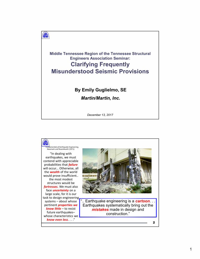
Topics
• R, Cd, Ωo
• Redundancy, ρ
• Vertical and Horizontal Combination of
Systems
• Bearing Wall or Building Frame?
• Analysis Procedures
• Structural Irregularities
3
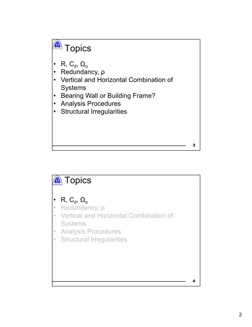
Topics
• R, Cd, Ωo
• Redundancy, ρ
• Vertical and Horizontal Combination of
Systems
• Analysis Procedures
• Structural Irregularities
4
3
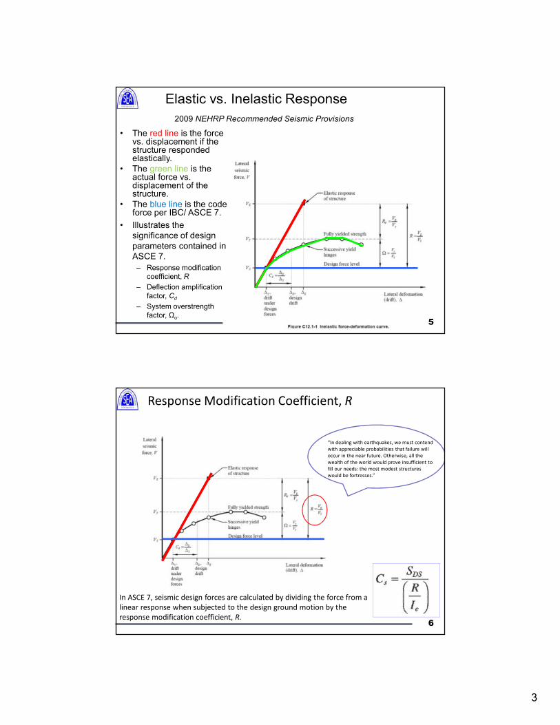
Elastic vs. Inelastic Response
• The red line is the force vs. displacement if the structure responded elastically.
• The green line is the actual force vs. displacement of the structure.
• The blue line is the code force per IBC/ ASCE 7.
• Illustrates the
significance of design
parameters contained in
ASCE 7.
– Response modification
coefficient, R
– Deflection amplification
factor, Cd
– System overstrength
factor, Ωo.
2009 NEHRP Recommended Seismic Provisions
5
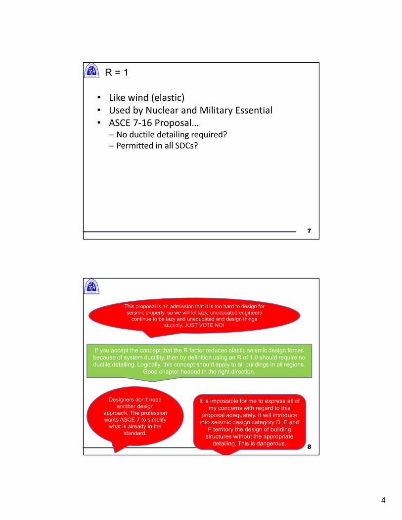
In ASCE 7, seismic design forces are calculated by dividing the force from a
linear response when subjected to the design ground motion by the
response modification coefficient, R.
Response Modification Coefficient, R
“In dealing with earthquakes, we must contend
with appreciable probabilities that failure will
occur in the near future. Otherwise, all the
wealth of the world would prove insufficient to
fill our needs: the most modest structures
would be fortresses.”
6
4
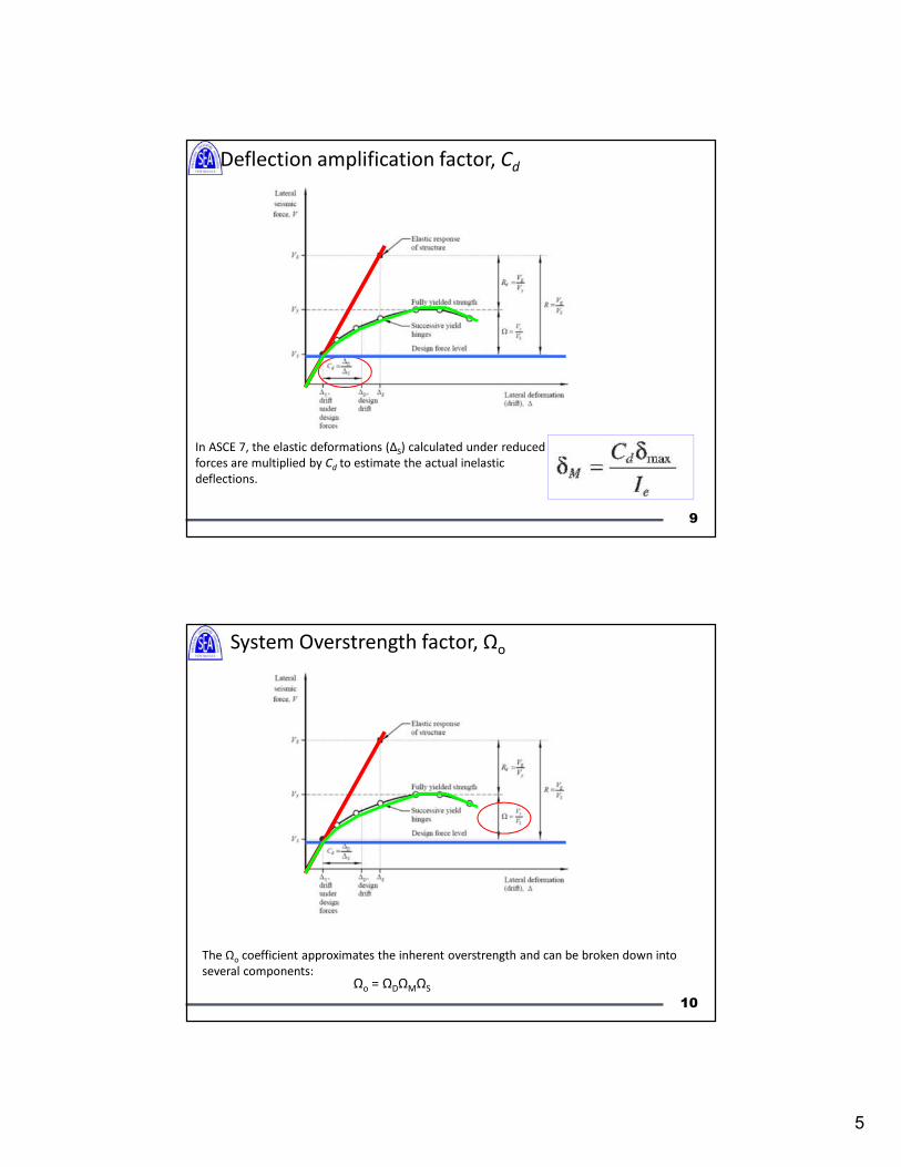
R = 1
• Like wind (elastic)
• Used by Nuclear and Military Essential
• ASCE 7-16 Proposal… – No ductile detailing required?
– Permitted in all SDCs?
7
If you accept the concept that the R factor reduces elastic seismic design forces
because of system ductility, then by definition using an R of 1.0 should require no
ductile detailing. Logically, this concept should apply to all buildings in all regions.
Good chapter headed in the right direction.
Designers don’t need
another design
approach. The profession
wants ASCE 7 to simplify
what is already in the
standard.
It is impossible for me to express all of
my concerns with regard to this
proposal adequately. It will introduce
into seismic design category D, E and
F territory the design of building
structures without the appropriate
detailing. This is dangerous.
This proposal is an admission that it is too hard to design for
seismic properly, so we will let lazy, uneducated engineers
continue to be lazy and uneducated and design things
stupidly. JUST VOTE NO!
8
5
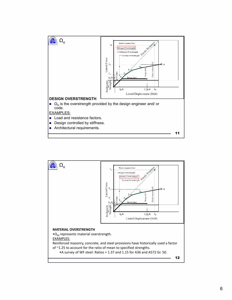
In ASCE 7, the elastic deformations (ΔS) calculated under reduced
forces are multiplied by Cd to estimate the actual inelastic
deflections.
Deflection amplification factor, Cd
9
The Ωo coefficient approximates the inherent overstrength and can be broken down into
several components:Ωo = ΩDΩMΩS
System Overstrength factor, Ωo
10
6
DESIGN OVERSTRENGTH
ΩD is the overstrength provided by the design engineer and/ or code.
EXAMPLES:
Load and resistance factors.
Design controlled by stiffness.
Architectural requirements.
11
Ωo
MATERIAL OVERSTRENGTH
•ΩM represents material overstrength.
EXAMPLES:
Reinforced masonry, concrete, and steel provisions have historically used a factor
of ~1.25 to account for the ratio of mean to specified strengths.
•A survey of WF steel: Ratios = 1.37 and 1.15 for A36 and A572 Gr. 50.
12
Ωo
7
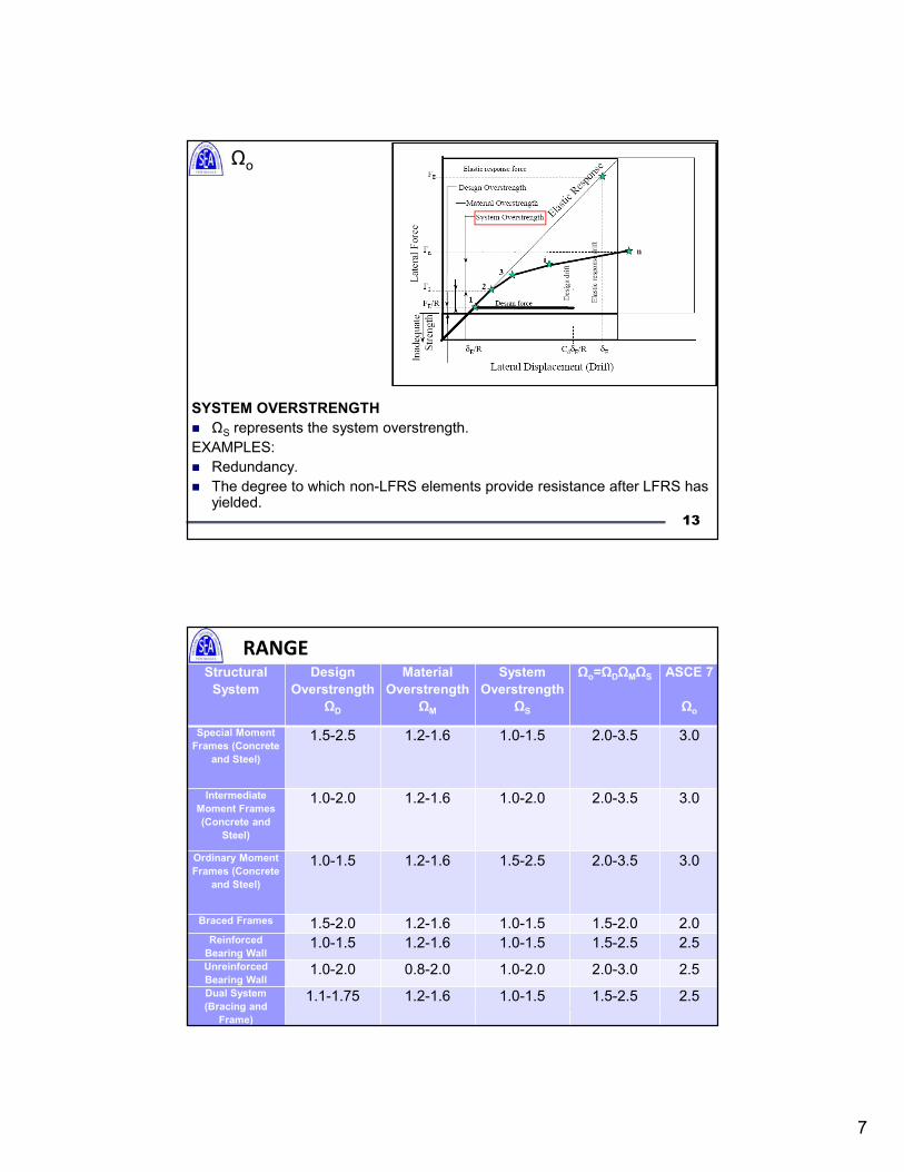
SYSTEM OVERSTRENGTH
ΩS represents the system overstrength.
EXAMPLES:
Redundancy.
The degree to which non-LFRS elements provide resistance after LFRS has yielded.
13
Ωo
RANGE OF Ωo FOR VARIOUS SYSTEMS:Structural
System
Design
Overstrength
ΩD
Material
Overstrength
ΩM
System
Overstrength
ΩS
Ωo=ΩDΩMΩS ASCE 7
Ωo
Special Moment
Frames (Concrete
and Steel)
1.5-2.5 1.2-1.6 1.0-1.5 2.0-3.5 3.0
Intermediate
Moment Frames
(Concrete and
Steel)
1.0-2.0 1.2-1.6 1.0-2.0 2.0-3.5 3.0
Ordinary Moment
Frames (Concrete
and Steel)
1.0-1.5 1.2-1.6 1.5-2.5 2.0-3.5 3.0
Braced Frames 1.5-2.0 1.2-1.6 1.0-1.5 1.5-2.0 2.0Reinforced
Bearing Wall1.0-1.5 1.2-1.6 1.0-1.5 1.5-2.5 2.5
Unreinforced
Bearing Wall1.0-2.0 0.8-2.0 1.0-2.0 2.0-3.0 2.5
Dual System
(Bracing and
Frame)
1.1-1.75 1.2-1.6 1.0-1.5 1.5-2.5 2.5
8
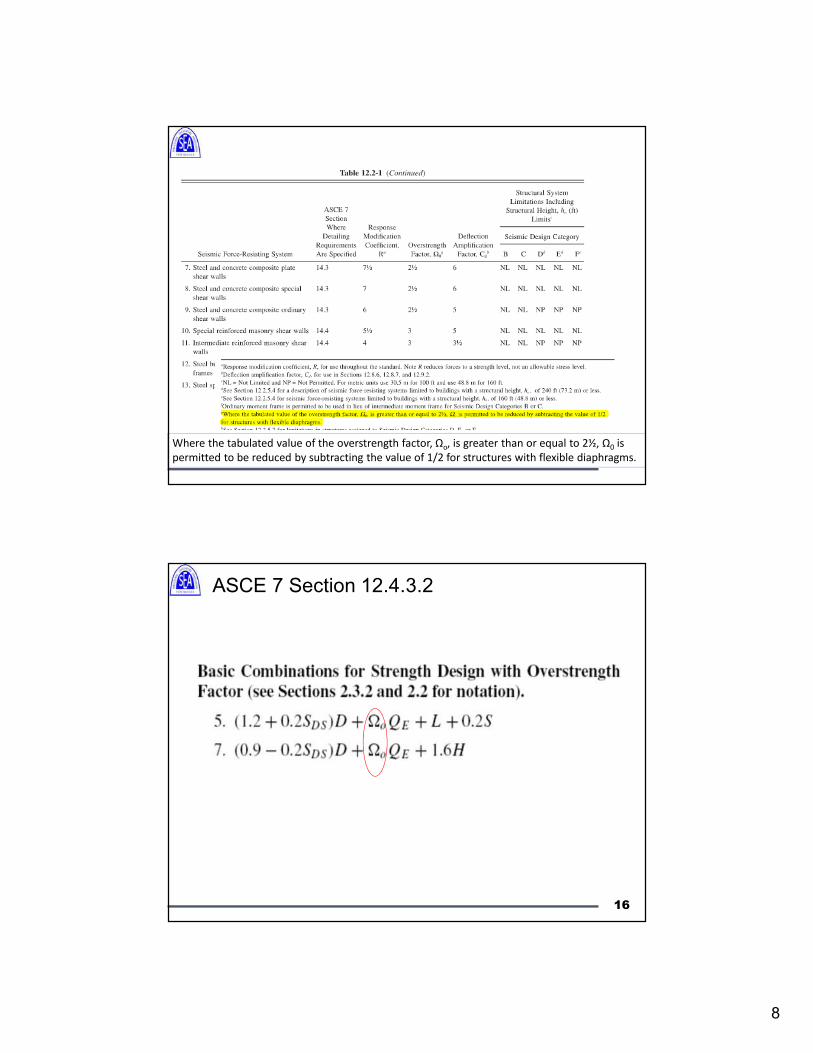
Where the tabulated value of the overstrength factor, Ωo, is greater than or equal to 2½, Ω0 is
permitted to be reduced by subtracting the value of 1/2 for structures with flexible diaphragms.
ASCE 7 Section 12.4.3.2
16
9
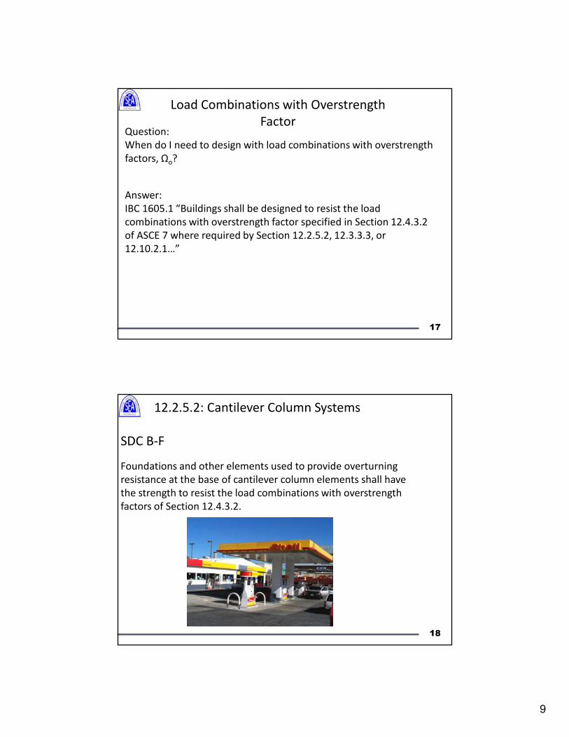
Load Combinations with Overstrength
FactorQuestion:
When do I need to design with load combinations with overstrength
factors, Ωo?
Answer:
IBC 1605.1 “Buildings shall be designed to resist the load
combinations with overstrength factor specified in Section 12.4.3.2
of ASCE 7 where required by Section 12.2.5.2, 12.3.3.3, or
12.10.2.1…”
17
12.2.5.2: Cantilever Column Systems
SDC B-F
Foundations and other elements used to provide overturning
resistance at the base of cantilever column elements shall have
the strength to resist the load combinations with overstrength
factors of Section 12.4.3.2.
18
10
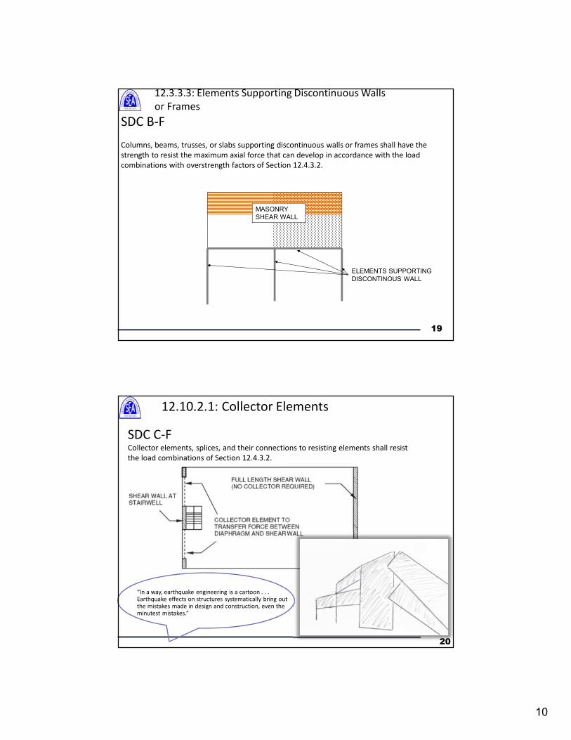
12.3.3.3: Elements Supporting Discontinuous Walls
or Frames
SDC B-F
Columns, beams, trusses, or slabs supporting discontinuous walls or frames shall have the
strength to resist the maximum axial force that can develop in accordance with the load
combinations with overstrength factors of Section 12.4.3.2.
MASONRY
SHEAR WALL
ELEMENTS SUPPORTING
DISCONTINOUS WALL
19
12.10.2.1: Collector Elements
SDC C-FCollector elements, splices, and their connections to resisting elements shall resist
the load combinations of Section 12.4.3.2.
“In a way, earthquake engineering is a cartoon . . . Earthquake effects on structures systematically bring out the mistakes made in design and construction, even the minutest mistakes.”
20
11
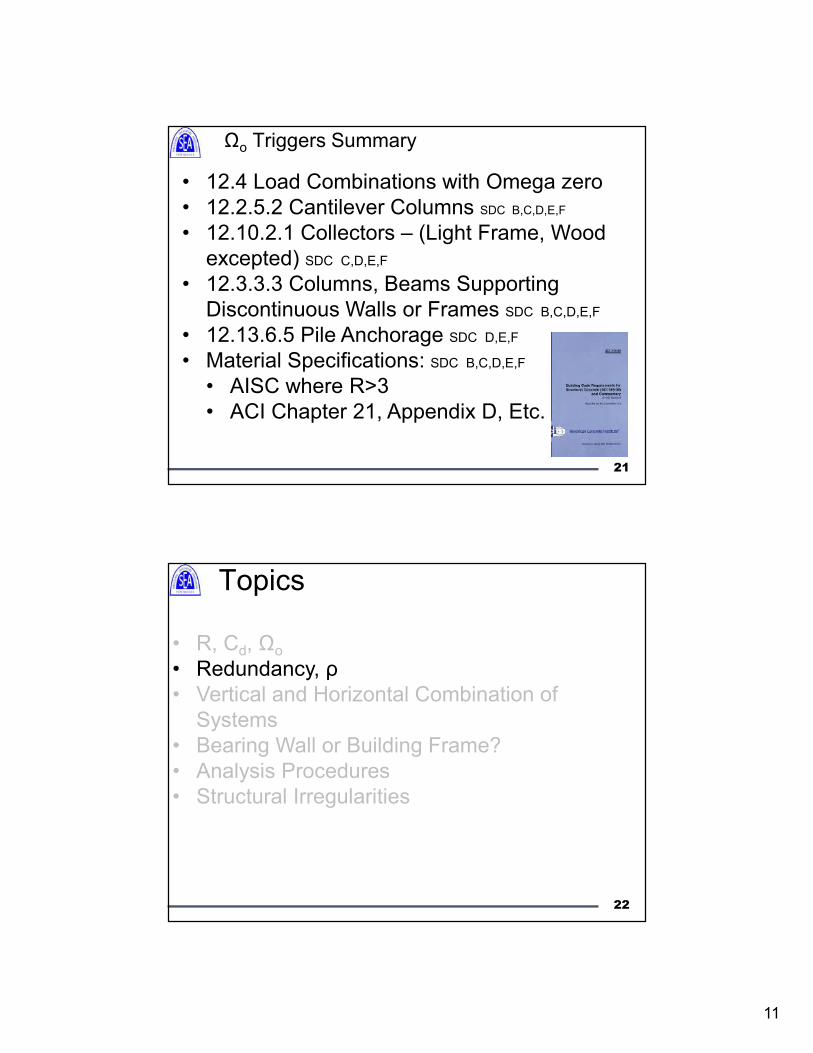
Ωo Triggers Summary
• 12.4 Load Combinations with Omega zero
• 12.2.5.2 Cantilever Columns SDC B,C,D,E,F
• 12.10.2.1 Collectors – (Light Frame, Wood
excepted) SDC C,D,E,F
• 12.3.3.3 Columns, Beams Supporting
Discontinuous Walls or Frames SDC B,C,D,E,F
• 12.13.6.5 Pile Anchorage SDC D,E,F
• Material Specifications: SDC B,C,D,E,F
• AISC where R>3
• ACI Chapter 21, Appendix D, Etc.
21
Topics
• R, Cd, Ωo
• Redundancy, ρ
• Vertical and Horizontal Combination of
Systems
• Bearing Wall or Building Frame?
• Analysis Procedures
• Structural Irregularities
22
12
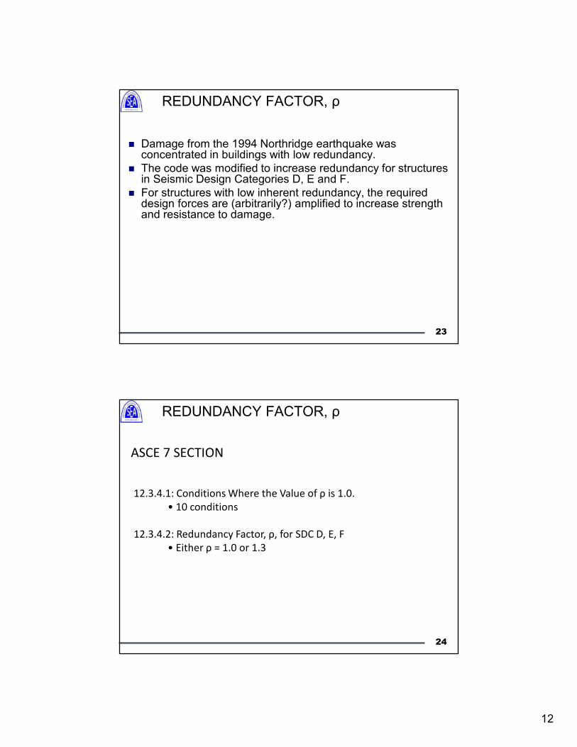
REDUNDANCY FACTOR, ρ
Damage from the 1994 Northridge earthquake was concentrated in buildings with low redundancy.
The code was modified to increase redundancy for structures in Seismic Design Categories D, E and F.
For structures with low inherent redundancy, the required design forces are (arbitrarily?) amplified to increase strength and resistance to damage.
23
ASCE 7 SECTION 12.3.4
12.3.4.1: Conditions Where the Value of ρ is 1.0.
• 10 conditions
12.3.4.2: Redundancy Factor, ρ, for SDC D, E, F
• Either ρ = 1.0 or 1.3
24
REDUNDANCY FACTOR, ρ
13
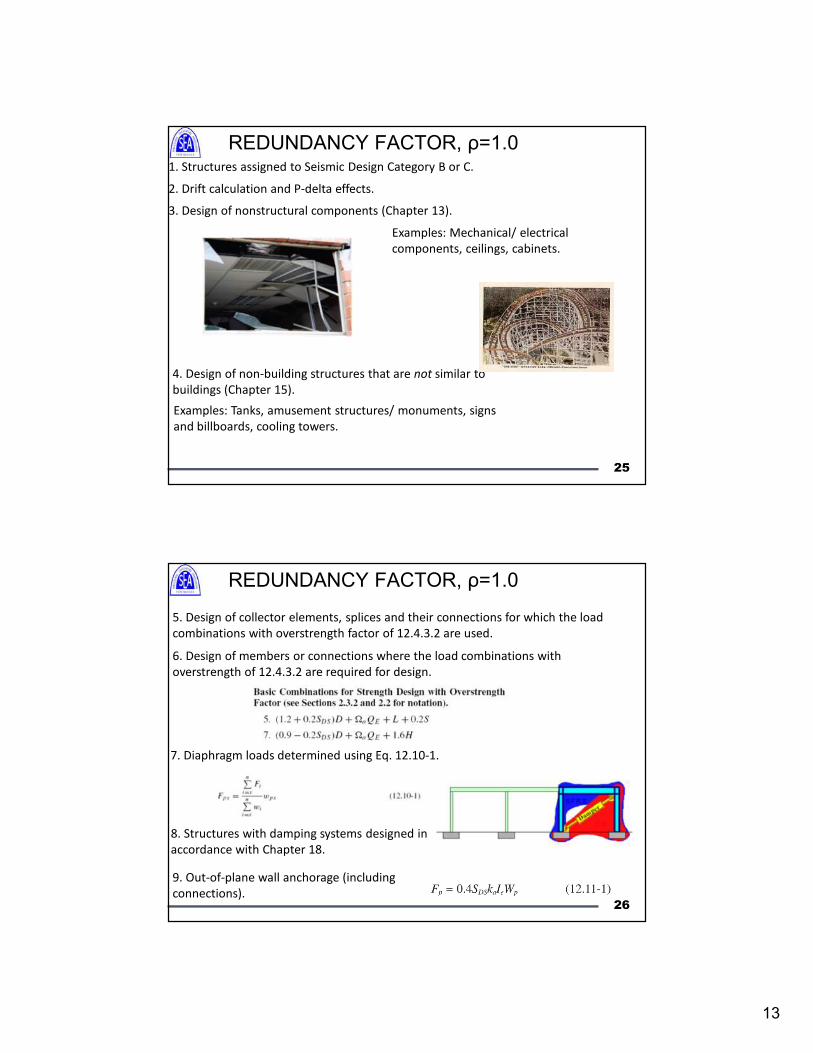
1. Structures assigned to Seismic Design Category B or C.
2. Drift calculation and P-delta effects.
3. Design of nonstructural components (Chapter 13).
4. Design of non-building structures that are not similar to
buildings (Chapter 15).
Examples: Tanks, amusement structures/ monuments, signs
and billboards, cooling towers.
Examples: Mechanical/ electrical
components, ceilings, cabinets.
25
REDUNDANCY FACTOR, ρ=1.0
6. Design of members or connections where the load combinations with
overstrength of 12.4.3.2 are required for design.
7. Diaphragm loads determined using Eq. 12.10-1.
8. Structures with damping systems designed in
accordance with Chapter 18.
5. Design of collector elements, splices and their connections for which the load
combinations with overstrength factor of 12.4.3.2 are used.
9. Out-of-plane wall anchorage (including
connections).26
REDUNDANCY FACTOR, ρ=1.0
14
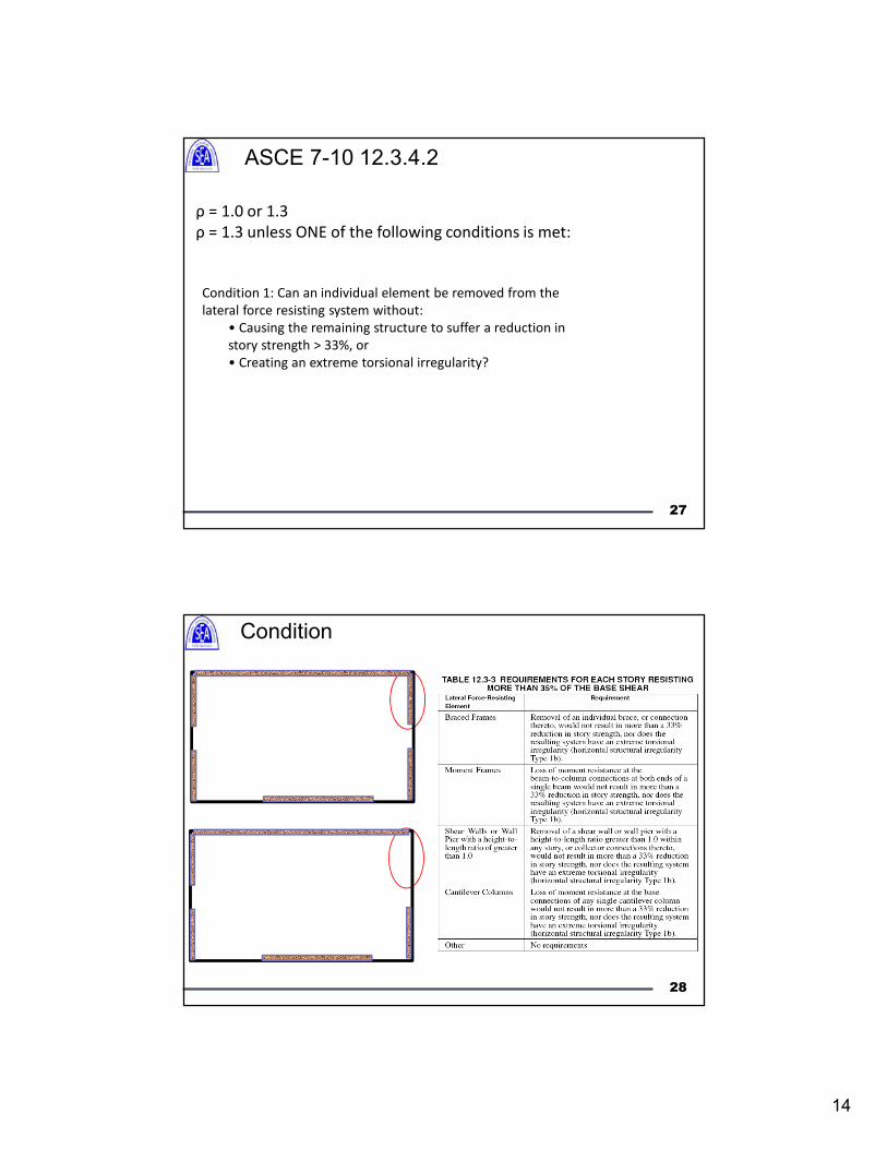
ASCE 7-10 12.3.4.2
ρ = 1.0 or 1.3
ρ = 1.3 unless ONE of the following conditions is met:
Condition 1: Can an individual element be removed from the
lateral force resisting system without:
• Causing the remaining structure to suffer a reduction in
story strength > 33%, or
• Creating an extreme torsional irregularity?
27
Condition 1: Requires Calculations!
28
15
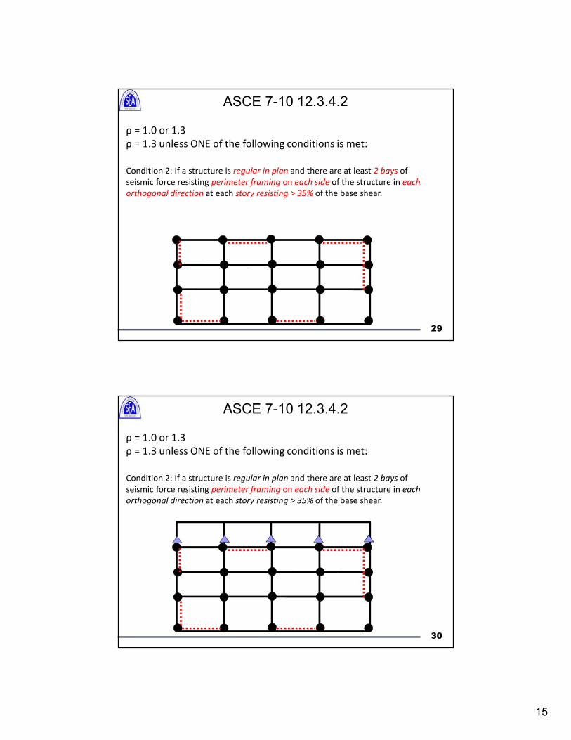
ASCE 7-10 12.3.4.2
ρ = 1.0 or 1.3
ρ = 1.3 unless ONE of the following conditions is met:
Condition 2: If a structure is regular in plan and there are at least 2 bays of
seismic force resisting perimeter framing on each side of the structure in each
orthogonal direction at each story resisting > 35% of the base shear.
29
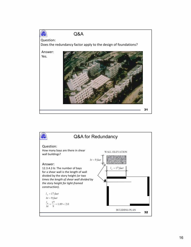
ρ = 1.0 or 1.3
ρ = 1.3 unless ONE of the following conditions is met:
Condition 2: If a structure is regular in plan and there are at least 2 bays of
seismic force resisting perimeter framing on each side of the structure in each
orthogonal direction at each story resisting > 35% of the base shear.
30
ASCE 7-10 12.3.4.2
16
Q&A for Redundancy
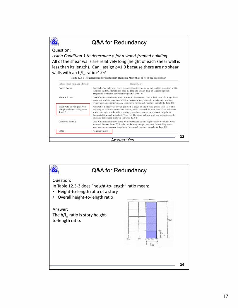
Question:
Does the redundancy factor apply to the design of foundations?
Answer:
Yes.
31
Question: How many bays are there in shear
wall buildings?
Answer:12.3.4.2-b: The number of bays
for a shear wall is the length of wall
divided by the story height (or two
times the length of shear wall divided by
the story height for light-framed
construction).
32
Q&A for Redundancy
17
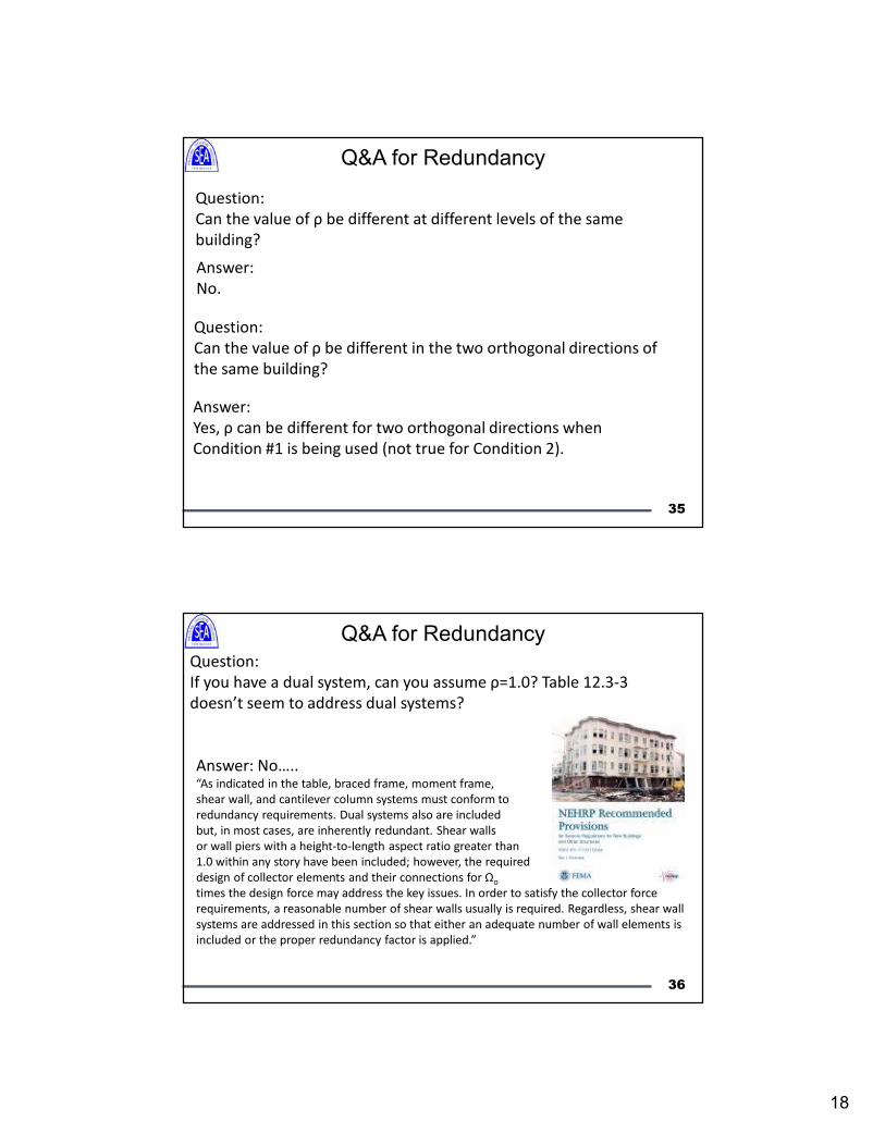
Question:
Using Condition 1 to determine ρ for a wood-framed building:
All of the shear walls are relatively long (height of each shear wall is
less than its length). Can I assign ρ=1.0 because there are no shear
walls with an h/lw ratio>1.0?
Answer: Yes33
Q&A for Redundancy
Question:
In Table 12.3-3 does “height-to-length” ratio mean:
• Height-to-length ratio of a story
• Overall height-to-length ratio
Answer:
The h/lw ratio is story height-
to-length ratio.
34
Q&A for Redundancy
18
Question:
Can the value of ρ be different at different levels of the same
building?
Answer:
No.
Question:
Can the value of ρ be different in the two orthogonal directions of
the same building?
Answer:
Yes, ρ can be different for two orthogonal directions when
Condition #1 is being used (not true for Condition 2).
35
Q&A for Redundancy
Question:
If you have a dual system, can you assume ρ=1.0? Table 12.3-3
doesn’t seem to address dual systems?
Answer: No….. “As indicated in the table, braced frame, moment frame,
shear wall, and cantilever column systems must conform to
redundancy requirements. Dual systems also are included
but, in most cases, are inherently redundant. Shear walls
or wall piers with a height-to-length aspect ratio greater than
1.0 within any story have been included; however, the required
design of collector elements and their connections for Ωo
times the design force may address the key issues. In order to satisfy the collector force
requirements, a reasonable number of shear walls usually is required. Regardless, shear wall
systems are addressed in this section so that either an adequate number of wall elements is
included or the proper redundancy factor is applied.”
36
Q&A for Redundancy
19
Question:
Does the redundancy factor need to be determined if dynamic
analysis is used?
Answer:
Yes. The method of analysis doesn’t make the building more or less
redundant.
37
Q&A for Redundancy
Topics
• R, Cd, Ωo
• Redundancy, ρ
• Vertical and Horizontal Combination of
Systems
• Bearing Wall or Building Frame?
• Analysis Procedures
• Structural Irregularities
38
20
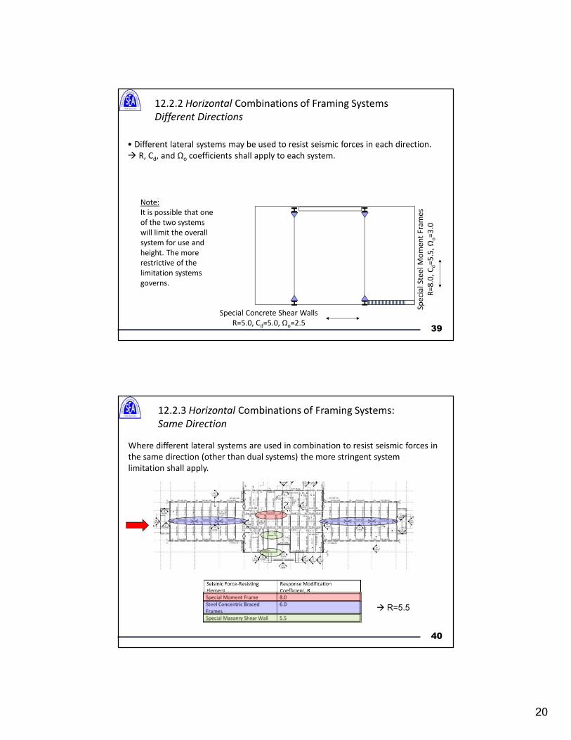
12.2.2 Horizontal Combinations of Framing Systems
Different Directions
• Different lateral systems may be used to resist seismic forces in each direction.
R, Cd, and Ωo coefficients shall apply to each system.
Special Concrete Shear Walls
R=5.0, Cd=5.0, Ωo=2.5
Sp
eci
al
Ste
el
Mo
me
nt
Fra
me
s
R=
8.0
, C
d=
5.5
, Ω
o=
3.0
Note:
It is possible that one
of the two systems
will limit the overall
system for use and
height. The more
restrictive of the
limitation systems
governs.H
H
HH
39
12.2.3 Horizontal Combinations of Framing Systems:
Same Direction
Where different lateral systems are used in combination to resist seismic forces in
the same direction (other than dual systems) the more stringent system
limitation shall apply.
R=5.5
40
21
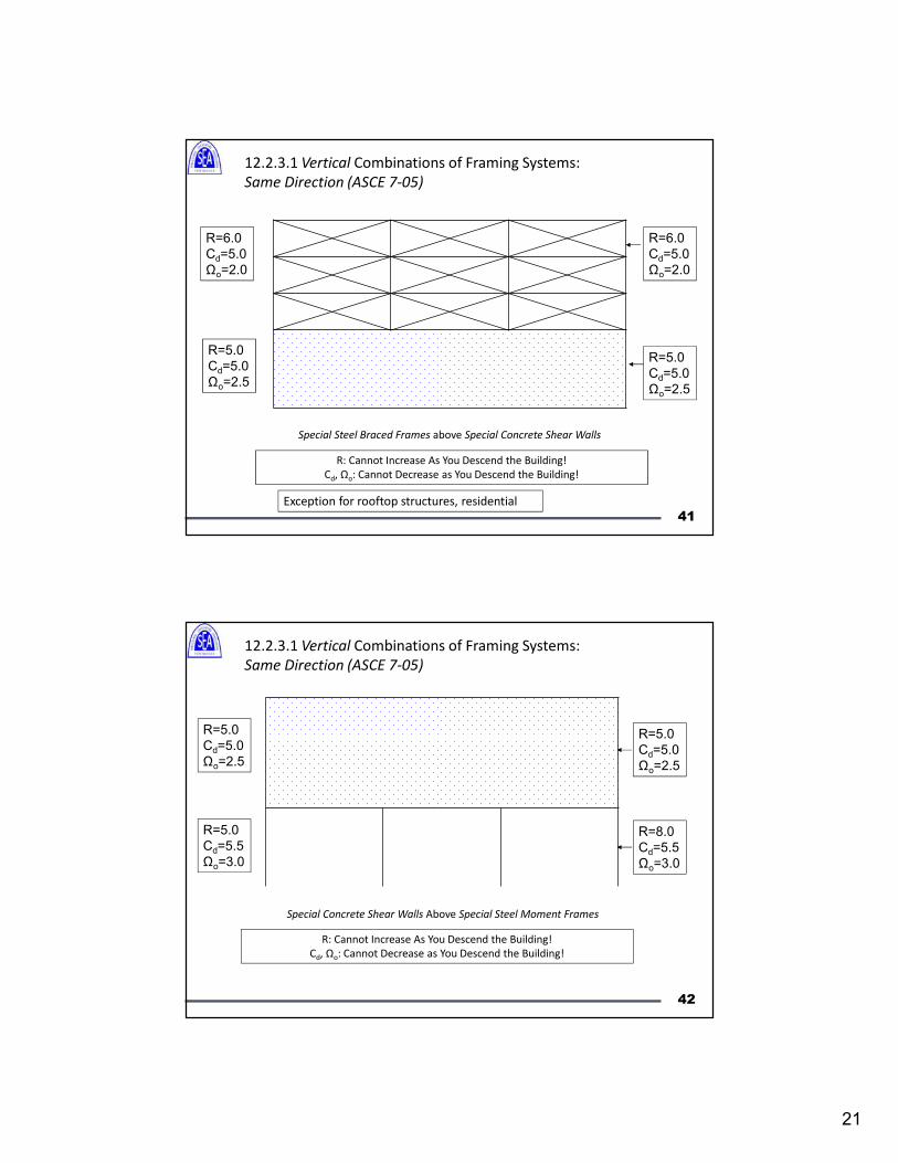
12.2.3.1 Vertical Combinations of Framing Systems:
Same Direction (ASCE 7-05)
Special Steel Braced Frames above Special Concrete Shear Walls
Exception for rooftop structures, residential
R=6.0
Cd=5.0
Ωo=2.0
R=5.0
Cd=5.0
Ωo=2.5
R: Cannot Increase As You Descend the Building!
Cd, Ωo: Cannot Decrease as You Descend the Building!
R=6.0
Cd=5.0
Ωo=2.0
R=5.0
Cd=5.0
Ωo=2.5
41
12.2.3.1 Vertical Combinations of Framing Systems:
Same Direction (ASCE 7-05)
Special Concrete Shear Walls Above Special Steel Moment Frames
R=8.0
Cd=5.5
Ωo=3.0
R=5.0
Cd=5.0
Ωo=2.5
R: Cannot Increase As You Descend the Building!
Cd, Ωo: Cannot Decrease as You Descend the Building!
R=5.0
Cd=5.0
Ωo=2.5
R=5.0
Cd=5.5
Ωo=3.0
42
22
12.2.3.1 Vertical Combinations of Framing Systems:
Same Direction (ASCE 7-05)
Special Steel Braced Frames Above Special Concrete Shear Walls Above Special Steel Moment Frames
R=8.0
Cd=5.5
Ωo=3.0
R=5.0
Cd=5.0
Ωo=2.5
R: Cannot Increase As You Descend the Building!
Cd, Ωo: Cannot Decrease as You Descend the Building!
R=6.0
Cd=5.0
Ωo=2.0
R=6.0
Cd=5.0
Ωo=2.0
R=5.0
Cd=5.0
Ωo=2.5
R=5.0
Cd=5.5
Ωo=3.0
43
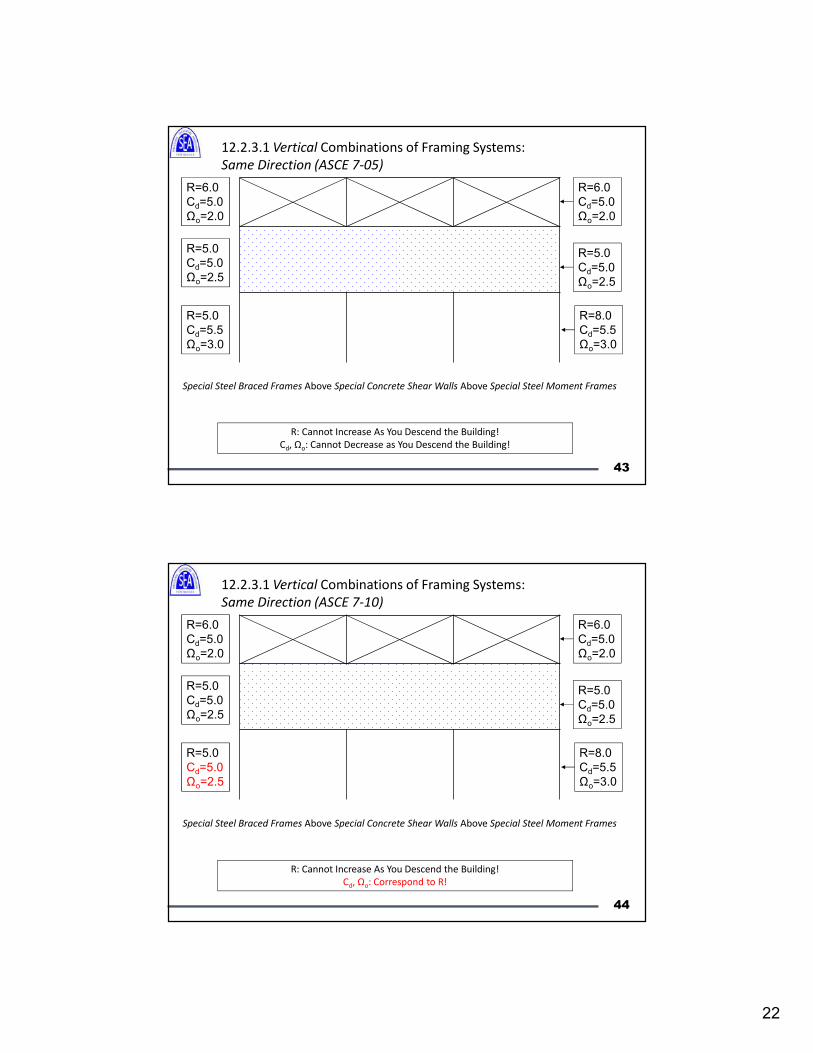
12.2.3.1 Vertical Combinations of Framing Systems:
Same Direction (ASCE 7-10)
Special Steel Braced Frames Above Special Concrete Shear Walls Above Special Steel Moment Frames
R=8.0
Cd=5.5
Ωo=3.0
R=5.0
Cd=5.0
Ωo=2.5
R: Cannot Increase As You Descend the Building!
Cd, Ωo: Correspond to R!
R=6.0
Cd=5.0
Ωo=2.0
R=6.0
Cd=5.0
Ωo=2.0
R=5.0
Cd=5.0
Ωo=2.5
R=5.0
Cd=5.0
Ωo=2.5
44
23
Topics
• R, Cd, Ωo
• Redundancy, ρ
• Vertical and Horizontal Combination of
Systems
• Bearing Wall or Building Frame?
• Analysis Procedures
• Structural Irregularities
45
46
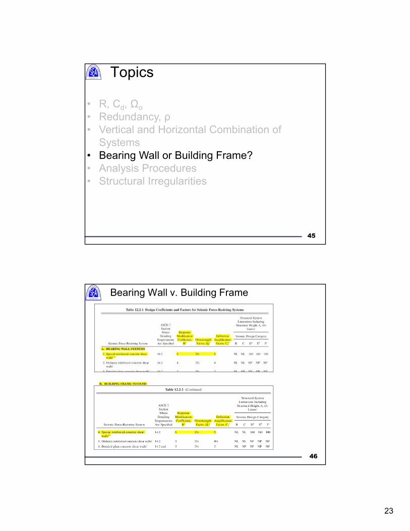
Bearing Wall v. Building Frame
24
47
WALL SYSTEM, BEARING: A structural system with bearing walls
providing support for all or major portions of the vertical loads. Shear walls
or braced frames provide seismic force resistance.
BUILDING FRAME SYSTEM: A structural system with an essentially
complete space frame providing support for vertical loads. Seismic force
resistance is provided by shear walls or braced frames.
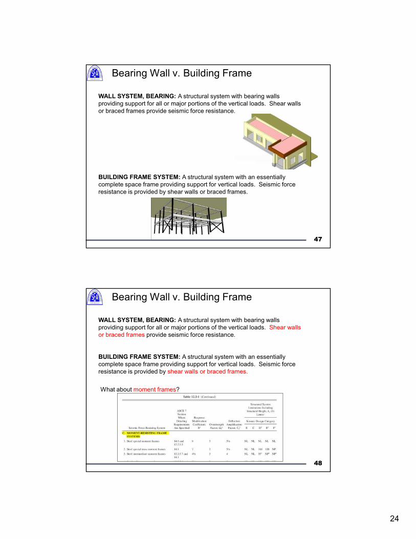
Bearing Wall v. Building Frame
48
WALL SYSTEM, BEARING: A structural system with bearing walls
providing support for all or major portions of the vertical loads. Shear walls
or braced frames provide seismic force resistance.
BUILDING FRAME SYSTEM: A structural system with an essentially
complete space frame providing support for vertical loads. Seismic force
resistance is provided by shear walls or braced frames.
What about moment frames?
Bearing Wall v. Building Frame
25
49
Question: If some of the gravity loads are resisted by shear walls, is it
possible to classify the system as a building frame system?
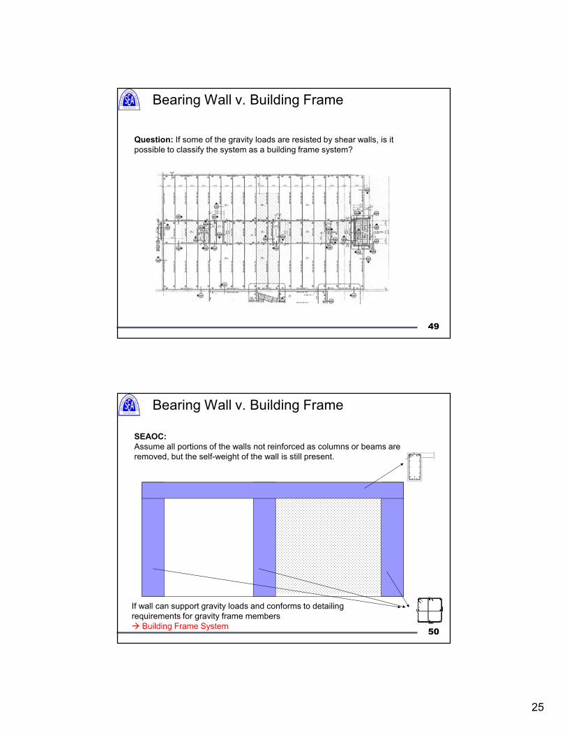
Bearing Wall v. Building Frame
50
SEAOC:
Assume all portions of the walls not reinforced as columns or beams are
removed, but the self-weight of the wall is still present.
If wall can support gravity loads and conforms to detailing
requirements for gravity frame members
Building Frame System
Bearing Wall v. Building Frame
26
51
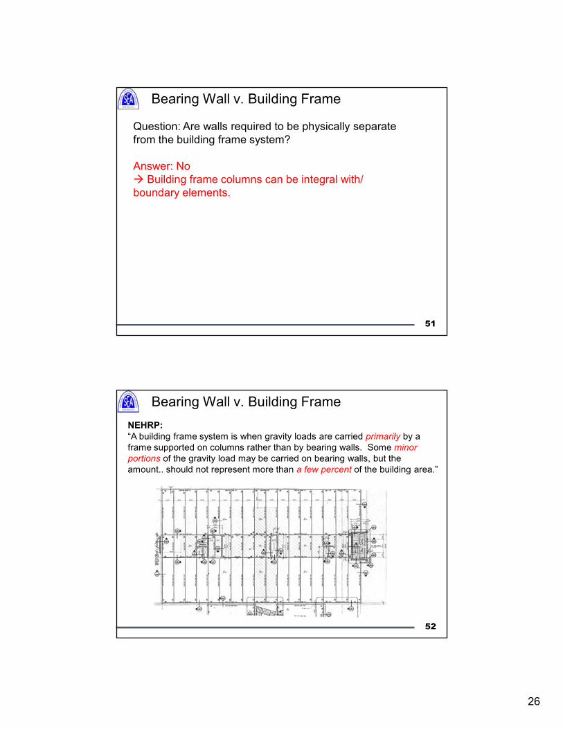
Question: Are walls required to be physically separate
from the building frame system?
Answer: No
Building frame columns can be integral with/
boundary elements.
Bearing Wall v. Building Frame
52
NEHRP:
“A building frame system is when gravity loads are carried primarily by a
frame supported on columns rather than by bearing walls. Some minor
portions of the gravity load may be carried on bearing walls, but the
amount.. should not represent more than a few percent of the building area.”
Bearing Wall v. Building Frame
27
Topics
• R, Cd, Ωo
• Redundancy, ρ
• Vertical and Horizontal Combination of
Systems
• Bearing Wall or Building Frame?
• Analysis Procedures
• Structural Irregularities
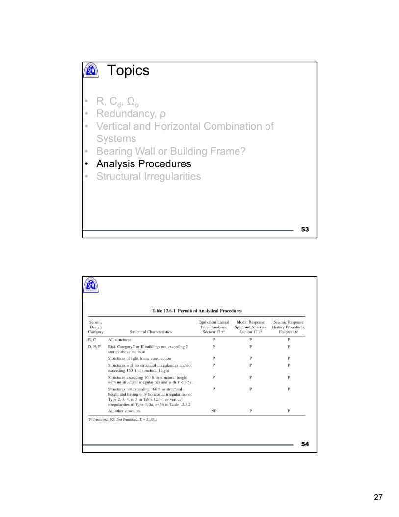
53
54
28
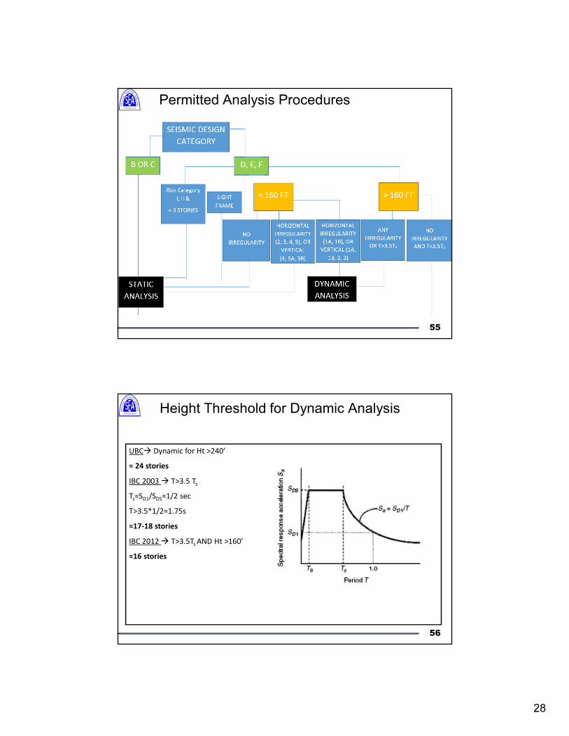
Permitted Analysis Procedures
55
Height Threshold for Dynamic Analysis
UBC Dynamic for Ht >240’
≈ 24 stories
IBC 2003 T>3.5 Ts
Ts=SD1/SDS≈1/2 sec
T>3.5*1/2=1.75s
≈17-18 stories
IBC 2012 T>3.5Ts AND Ht >160’
≈16 stories
56
29
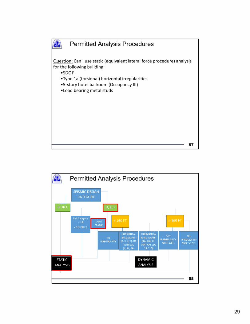
57
Question: Can I use static (equivalent lateral force procedure) analysis
for the following building:
•SDC F
•Type 1a (torsional) horizontal irregularities
•5-story hotel ballroom (Occupancy III)
•Load bearing metal studs
Permitted Analysis Procedures
Permitted Analysis Procedures
58
30
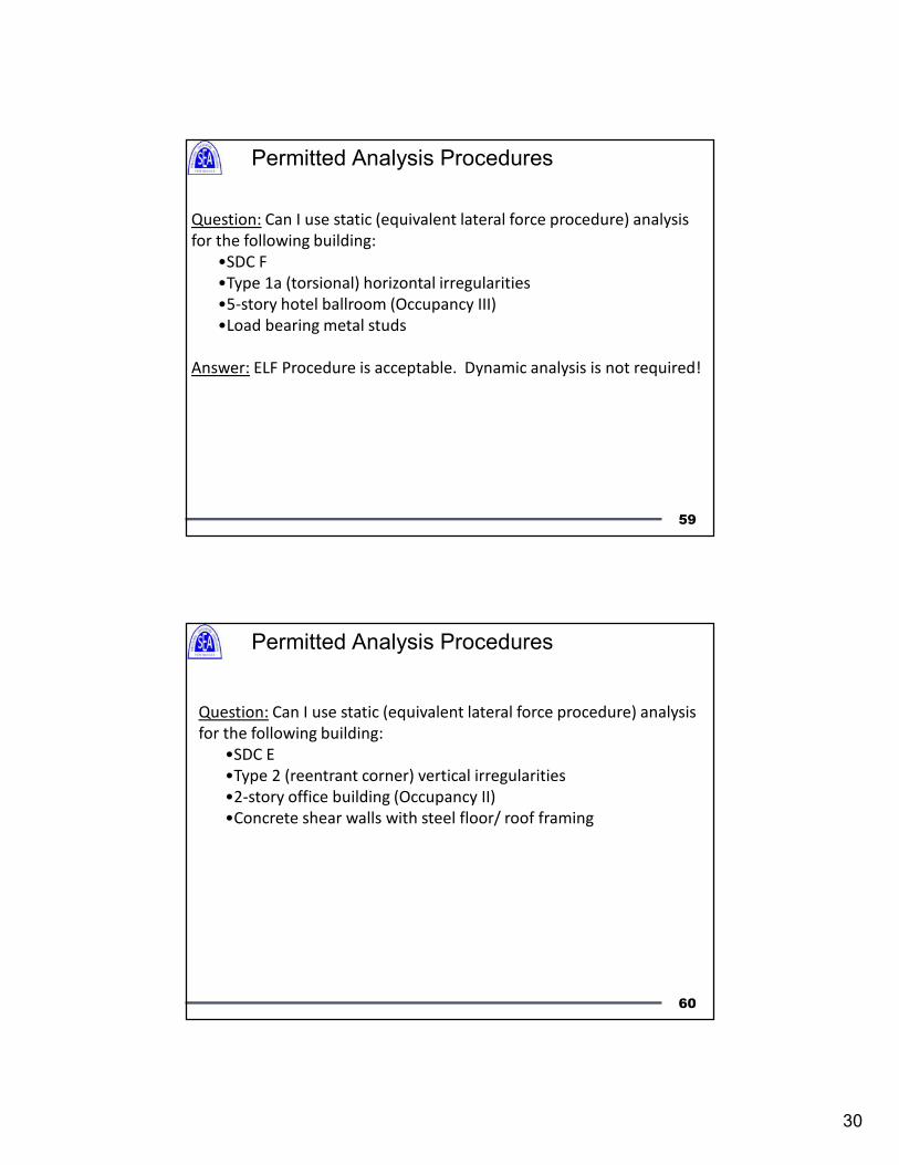
59
Question: Can I use static (equivalent lateral force procedure) analysis
for the following building:
•SDC F
•Type 1a (torsional) horizontal irregularities
•5-story hotel ballroom (Occupancy III)
•Load bearing metal studs
Answer: ELF Procedure is acceptable. Dynamic analysis is not required!
Permitted Analysis Procedures
60
Question: Can I use static (equivalent lateral force procedure) analysis
for the following building:
•SDC E
•Type 2 (reentrant corner) vertical irregularities
•2-story office building (Occupancy II)
•Concrete shear walls with steel floor/ roof framing
Permitted Analysis Procedures
31
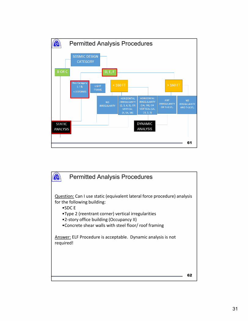
Permitted Analysis Procedures
61
62
Question: Can I use static (equivalent lateral force procedure) analysis
for the following building:
•SDC E
•Type 2 (reentrant corner) vertical irregularities
•2-story office building (Occupancy II)
•Concrete shear walls with steel floor/ roof framing
Answer: ELF Procedure is acceptable. Dynamic analysis is not
required!
Permitted Analysis Procedures
32
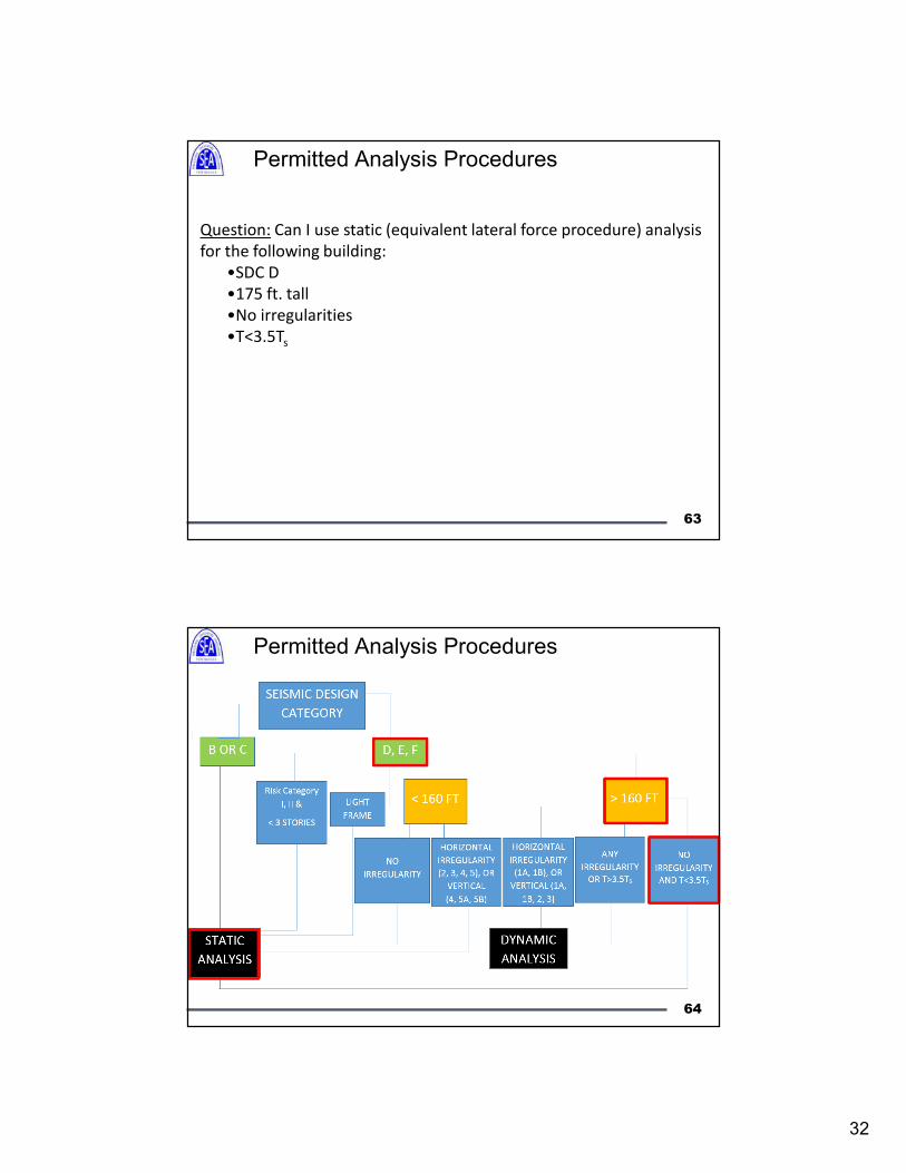
63
Question: Can I use static (equivalent lateral force procedure) analysis
for the following building:
•SDC D
•175 ft. tall
•No irregularities
•T<3.5Ts
Permitted Analysis Procedures
Permitted Analysis Procedures
64
33
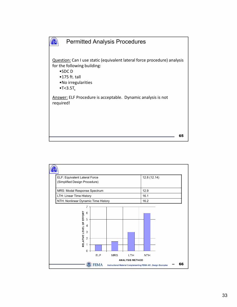
65
Question: Can I use static (equivalent lateral force procedure) analysis
for the following building:
•SDC D
•175 ft. tall
•No irregularities
•T<3.5Ts
Answer: ELF Procedure is acceptable. Dynamic analysis is not
required!
Permitted Analysis Procedures
ELF: Equivalent Lateral Force
(Simplified Design Procedure)
12.8 (12.14)
MRS: Modal Response Spectrum 12.9
LTH: Linear Time History 16.1
NTH: Nonlinear Dynamic Time History 16.2
66
34
Topics
• R, Cd, Ωo
• Redundancy, ρ
• Vertical and Horizontal Combination of
Systems
• Bearing Wall or Building Frame?
• Analysis Procedures
• Structural Irregularities
67
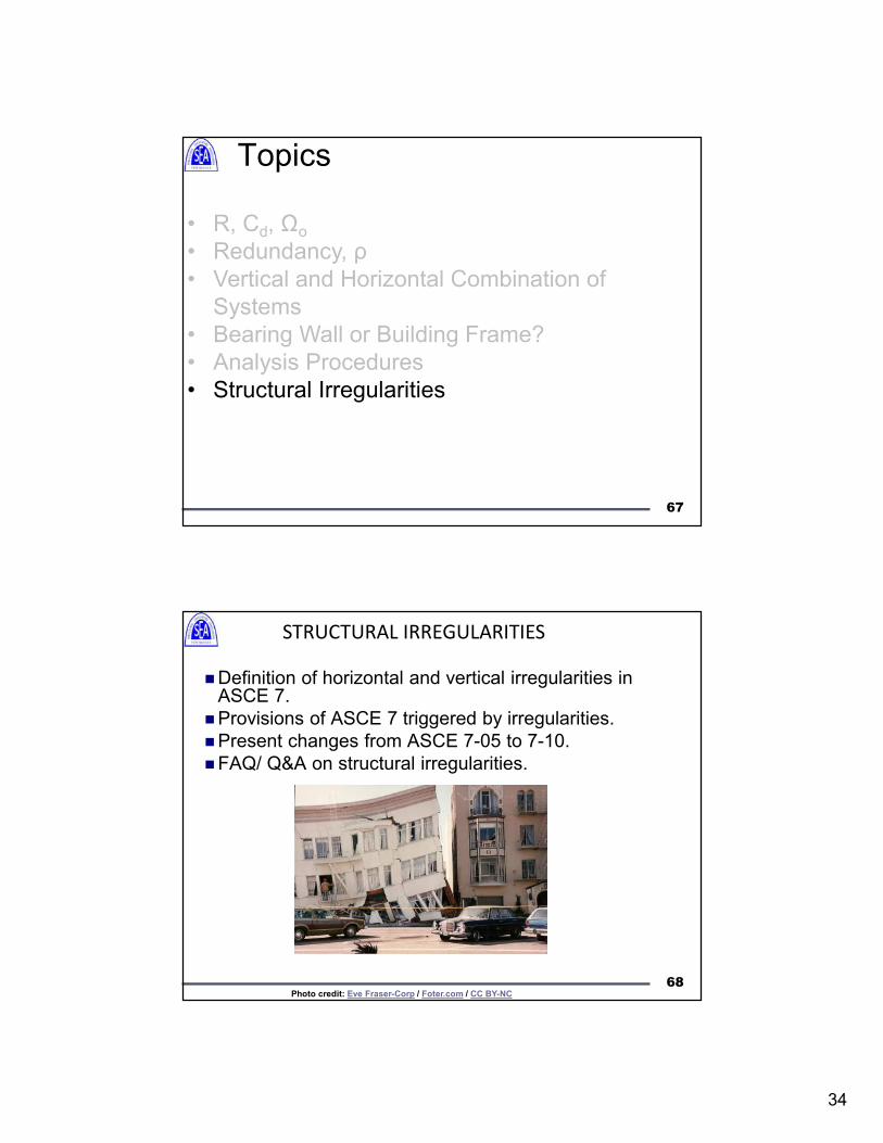
Definition of horizontal and vertical irregularities in ASCE 7.
Provisions of ASCE 7 triggered by irregularities.
Present changes from ASCE 7-05 to 7-10.
FAQ/ Q&A on structural irregularities.
STRUCTURAL IRREGULARITIES
Photo credit: Eve Fraser-Corp / Foter.com / CC BY-NC
68
35
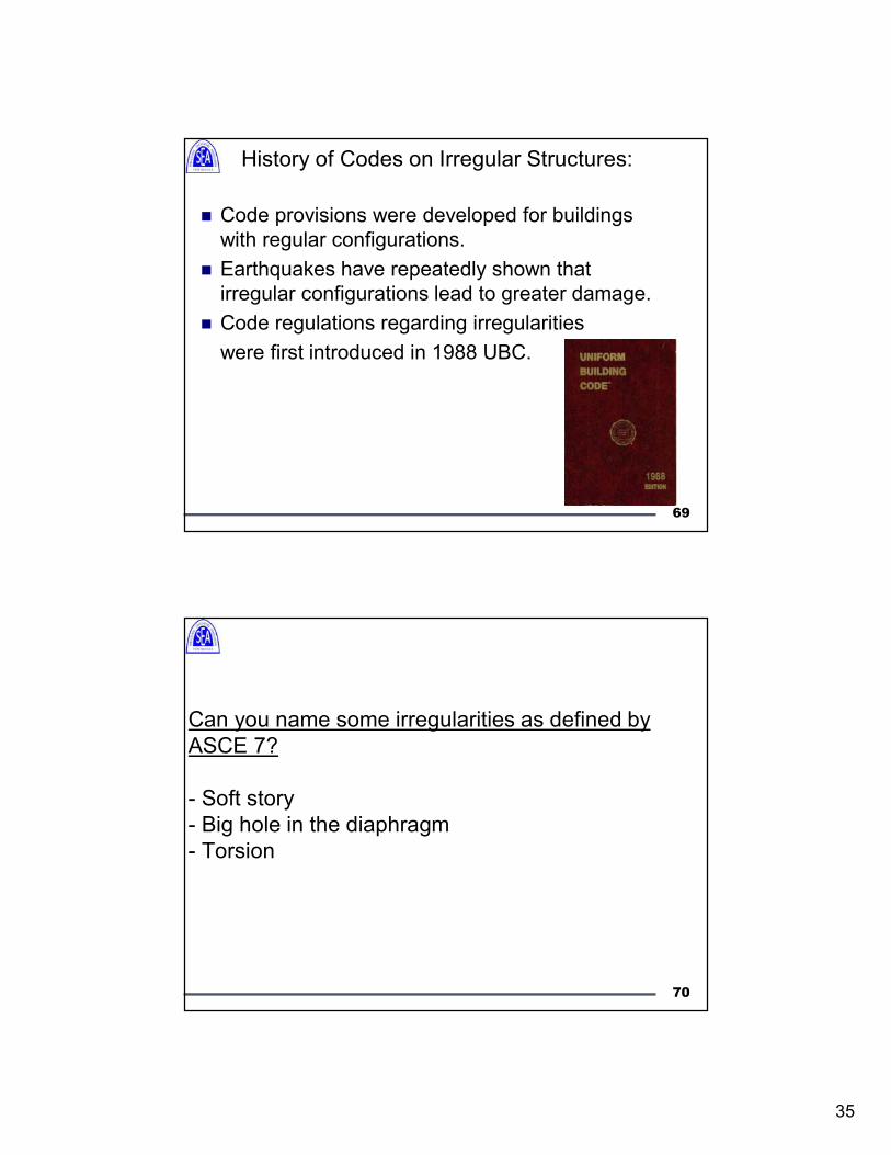
History of Codes on Irregular Structures:
Code provisions were developed for buildings
with regular configurations.
Earthquakes have repeatedly shown that
irregular configurations lead to greater damage.
Code regulations regarding irregularities
were first introduced in 1988 UBC.
69
Can you name some irregularities as defined by
ASCE 7?
- Soft story
- Big hole in the diaphragm
- Torsion
70
36
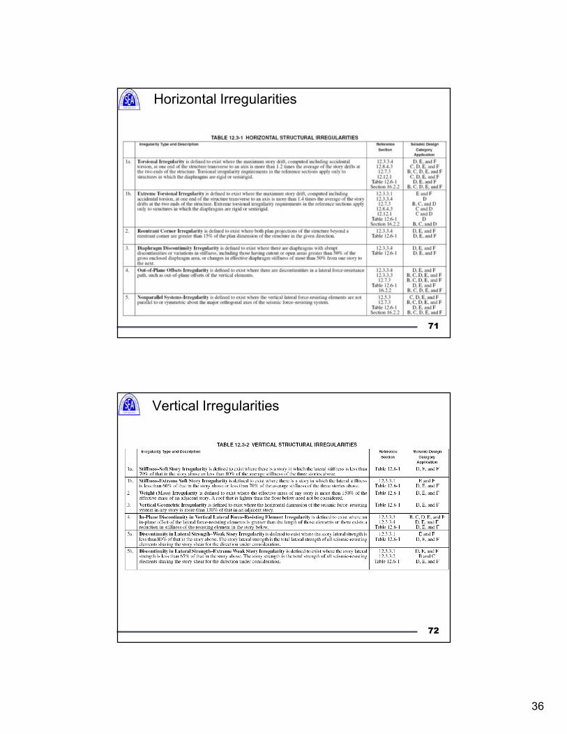
Horizontal Irregularities
71
Vertical Irregularities
72
37
Horizontal Irregularities: Type 1a and 1b
73
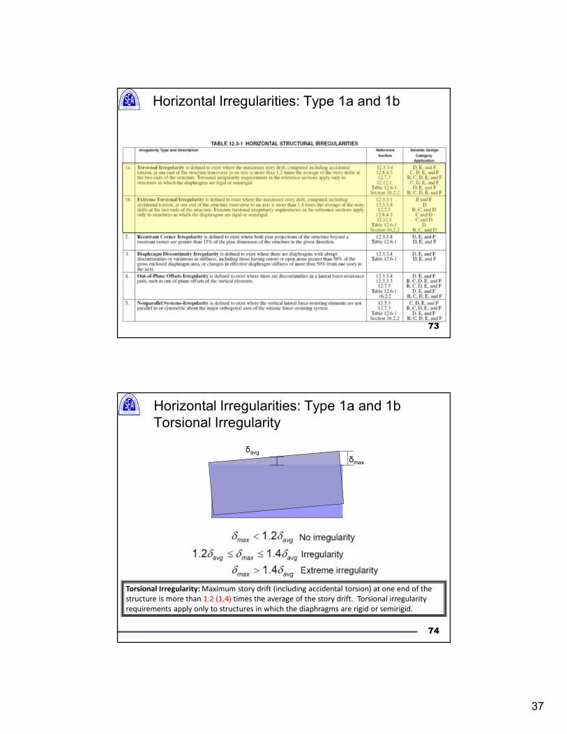
Horizontal Irregularities: Type 1a and 1b
Torsional Irregularity
Torsional Irregularity: Maximum story drift (including accidental torsion) at one end of the
structure is more than 1.2 (1.4) times the average of the story drift. Torsional irregularity
requirements apply only to structures in which the diaphragms are rigid or semirigid.
74
δmax
δavg
38
75
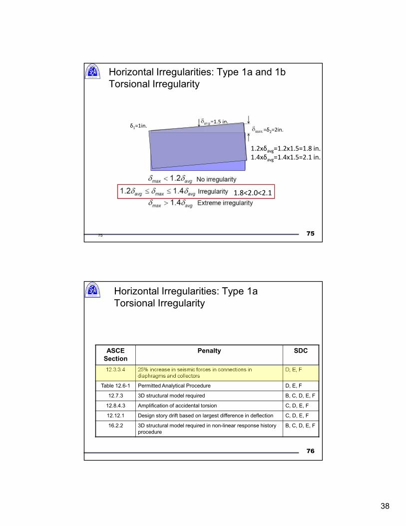
Horizontal Irregularities: Type 1a and 1b
Torsional Irregularity
δ1=1in.=δ2=2in.
=1.5 in.
1.8<2.0<2.1
1.2xδavg=1.2x1.5=1.8 in.
1.4xδavg=1.4x1.5=2.1 in.
75
76
Horizontal Irregularities: Type 1a
Torsional Irregularity
ASCE
Section
Penalty SDC
12.3.3.4 25% increase in seismic forces in connections in
diaphragms and collectors
D, E, F
Table 12.6-1 Permitted Analytical Procedure D, E, F
12.7.3 3D structural model required B, C, D, E, F
12.8.4.3 Amplification of accidental torsion C, D, E, F
12.12.1 Design story drift based on largest difference in deflection C, D, E, F
16.2.2 3D structural model required in non-linear response history
procedure
B, C, D, E, F
39
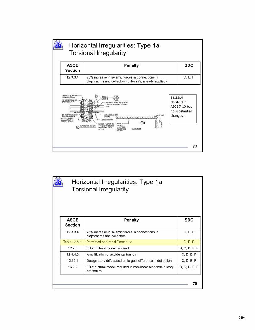
77
Horizontal Irregularities: Type 1a
Torsional Irregularity
ASCE
Section
Penalty SDC
12.3.3.4 25% increase in seismic forces in connections in
diaphragms and collectors (unless Ωo already applied)
D, E, F
12.3.3.4
clarified in
ASCE 7-10 but
no substantial
changes.
78
Horizontal Irregularities: Type 1a
Torsional Irregularity
ASCE
Section
Penalty SDC
12.3.3.4 25% increase in seismic forces in connections in
diaphragms and collectors
D, E, F
Table 12.6-1 Permitted Analytical Procedure D, E, F
12.7.3 3D structural model required B, C, D, E, F
12.8.4.3 Amplification of accidental torsion C, D, E, F
12.12.1 Design story drift based on largest difference in deflection C, D, E, F
16.2.2 3D structural model required in non-linear response history
procedure
B, C, D, E, F
40
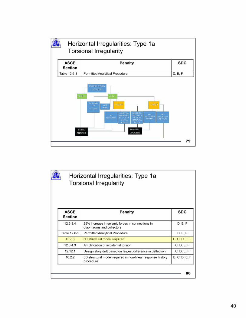
79
Horizontal Irregularities: Type 1a
Torsional Irregularity
ASCE
Section
Penalty SDC
Table 12.6-1 Permitted Analytical Procedure D, E, F
80
Horizontal Irregularities: Type 1a
Torsional Irregularity
ASCE
Section
Penalty SDC
12.3.3.4 25% increase in seismic forces in connections in
diaphragms and collectors
D, E, F
Table 12.6-1 Permitted Analytical Procedure D, E, F
12.7.3 3D structural model required B, C, D, E, F
12.8.4.3 Amplification of accidental torsion C, D, E, F
12.12.1 Design story drift based on largest difference in deflection C, D, E, F
16.2.2 3D structural model required in non-linear response history
procedure
B, C, D, E, F
41
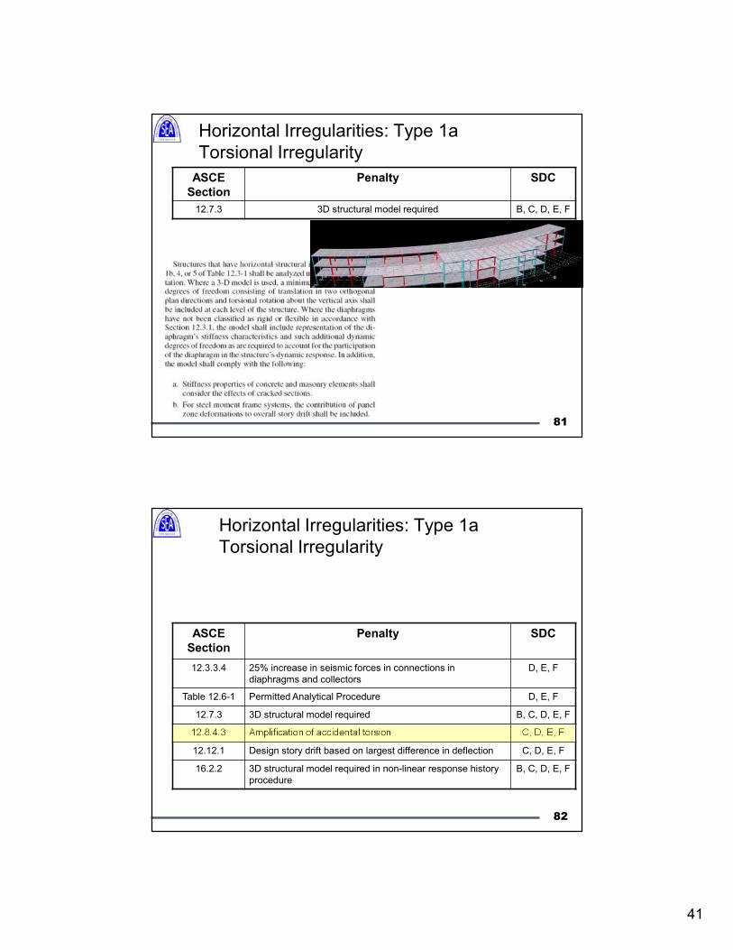
81
Horizontal Irregularities: Type 1a
Torsional Irregularity
ASCE
Section
Penalty SDC
12.7.3 3D structural model required B, C, D, E, F
82
Horizontal Irregularities: Type 1a
Torsional Irregularity
ASCE
Section
Penalty SDC
12.3.3.4 25% increase in seismic forces in connections in
diaphragms and collectors
D, E, F
Table 12.6-1 Permitted Analytical Procedure D, E, F
12.7.3 3D structural model required B, C, D, E, F
12.8.4.3 Amplification of accidental torsion C, D, E, F
12.12.1 Design story drift based on largest difference in deflection C, D, E, F
16.2.2 3D structural model required in non-linear response history
procedure
B, C, D, E, F
42
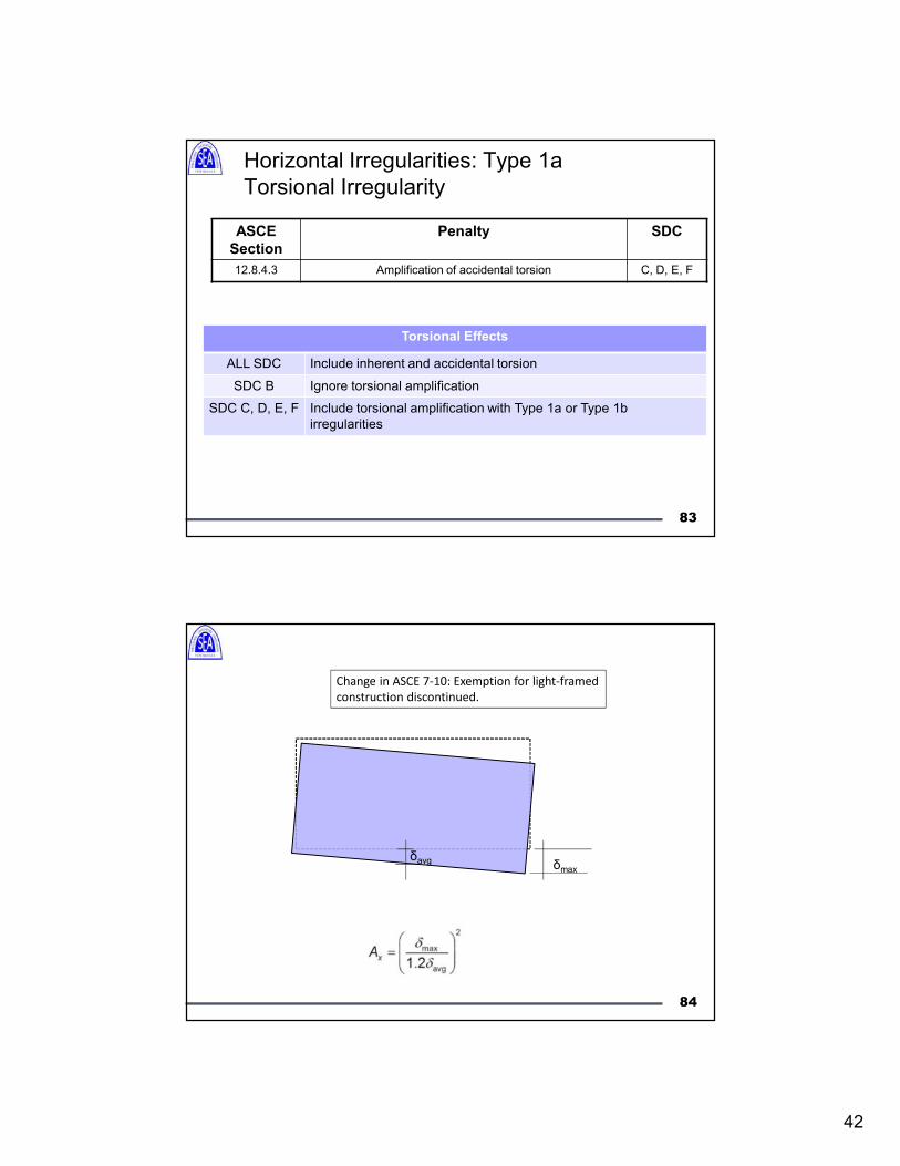
83
Horizontal Irregularities: Type 1a
Torsional Irregularity
ASCE
Section
Penalty SDC
12.8.4.3 Amplification of accidental torsion C, D, E, F
Torsional Effects
ALL SDC Include inherent and accidental torsion
SDC B Ignore torsional amplification
SDC C, D, E, F Include torsional amplification with Type 1a or Type 1b
irregularities
Change in ASCE 7-10: Exemption for light-framed
construction discontinued.
δmax
δavg
84
43
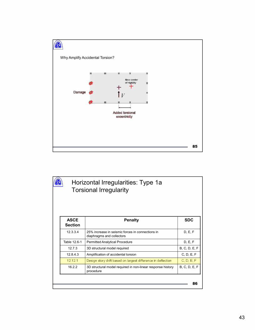
Why Amplify Accidental Torsion?
85
86
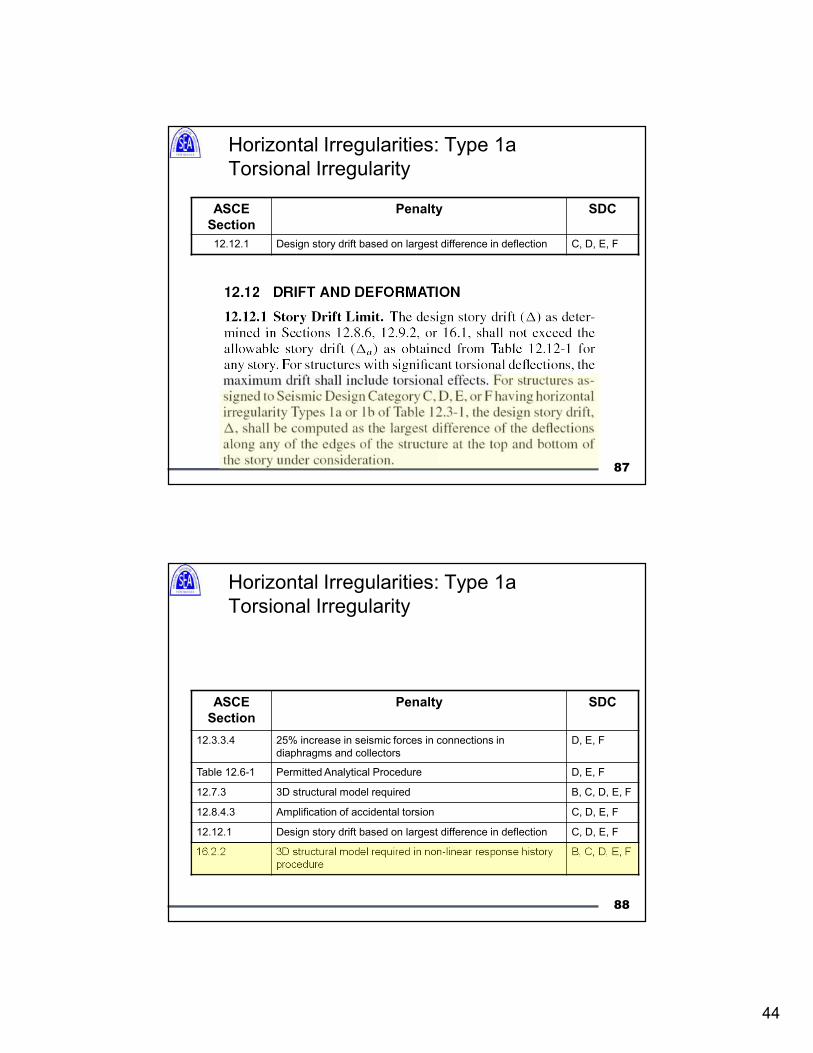
Horizontal Irregularities: Type 1a
Torsional Irregularity
ASCE
Section
Penalty SDC
12.3.3.4 25% increase in seismic forces in connections in
diaphragms and collectors
D, E, F
Table 12.6-1 Permitted Analytical Procedure D, E, F
12.7.3 3D structural model required B, C, D, E, F
12.8.4.3 Amplification of accidental torsion C, D, E, F
12.12.1 Design story drift based on largest difference in deflection C, D, E, F
16.2.2 3D structural model required in non-linear response history
procedure
B, C, D, E, F
44
87
Horizontal Irregularities: Type 1a
Torsional Irregularity
ASCE
Section
Penalty SDC
12.12.1 Design story drift based on largest difference in deflection C, D, E, F
88
Horizontal Irregularities: Type 1a
Torsional Irregularity
ASCE
Section
Penalty SDC
12.3.3.4 25% increase in seismic forces in connections in
diaphragms and collectors
D, E, F
Table 12.6-1 Permitted Analytical Procedure D, E, F
12.7.3 3D structural model required B, C, D, E, F
12.8.4.3 Amplification of accidental torsion C, D, E, F
12.12.1 Design story drift based on largest difference in deflection C, D, E, F
16.2.2 3D structural model required in non-linear response history
procedure
B, C, D, E, F
45
89
Horizontal Irregularities: Type 1a
Torsional Irregularity
ASCE
Section
Penalty SDC
16.2.2 3D structural model required in non-linear response history
procedure
B, C, D, E, F
90
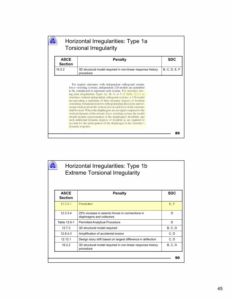
Horizontal Irregularities: Type 1b
Extreme Torsional Irregularity
ASCE
Section
Penalty SDC
12.3.3.1 Prohibited E, F
12.3.3.4 25% increase in seismic forces in connections in
diaphragms and collectors
D
Table 12.6-1 Permitted Analytical Procedure D
12.7.3 3D structural model required B, C, D
12.8.4.3 Amplification of accidental torsion C, D
12.12.1 Design story drift based on largest difference in deflection C, D
16.2.2 3D structural model required in non-linear response history
procedure
B, C, D
46
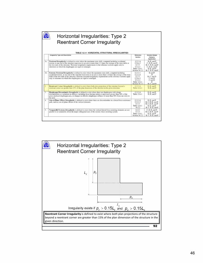
Horizontal Irregularities: Type 2
Reentrant Corner Irregularity
Horizontal Irregularities: Type 2
Reentrant Corner Irregularity
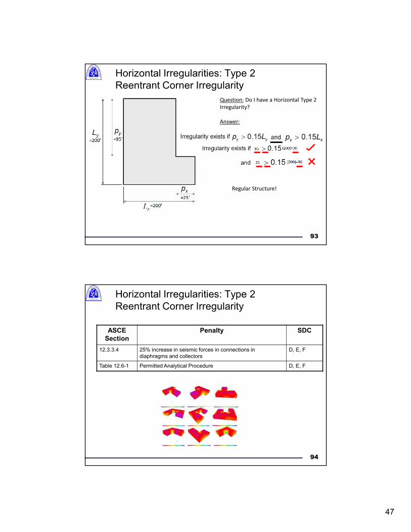
Reentrant Corner Irregularity is defined to exist where both plan projections of the structure
beyond a reentrant corner are greater than 15% of the plan dimension of the structure in the
given direction.
92
47
Question: Do I have a Horizontal Type 2
Irregularity?
Answer:
Regular Structure!
Horizontal Irregularities: Type 2
Reentrant Corner Irregularity
93
94
Horizontal Irregularities: Type 2
Reentrant Corner Irregularity
ASCE
Section
Penalty SDC
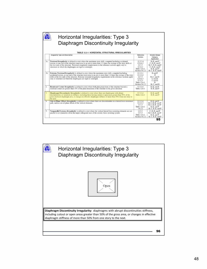
12.3.3.4 25% increase in seismic forces in connections in
diaphragms and collectors
D, E, F
Table 12.6-1 Permitted Analytical Procedure D, E, F
48
Horizontal Irregularities: Type 3
Diaphragm Discontinuity Irregularity
95
Horizontal Irregularities: Type 3
Diaphragm Discontinuity Irregularity
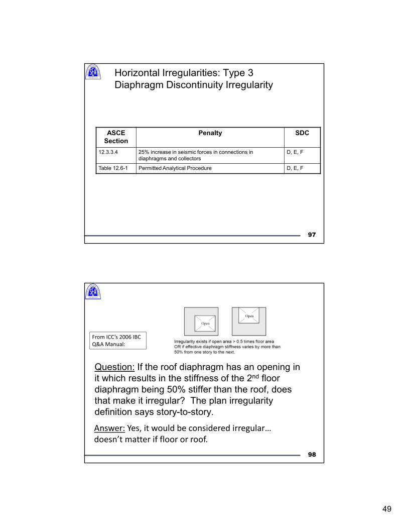
Diaphragm Discontinuity Irregularity: diaphragms with abrupt discontinuities stiffness,
including cutout or open areas greater than 50% of the gross area, or changes in effective
diaphragm stiffness of more than 50% from one story to the next.
96
49
97
Horizontal Irregularities: Type 3
Diaphragm Discontinuity Irregularity
ASCE
Section
Penalty SDC
12.3.3.4 25% increase in seismic forces in connections in
diaphragms and collectors
D, E, F
Table 12.6-1 Permitted Analytical Procedure D, E, F
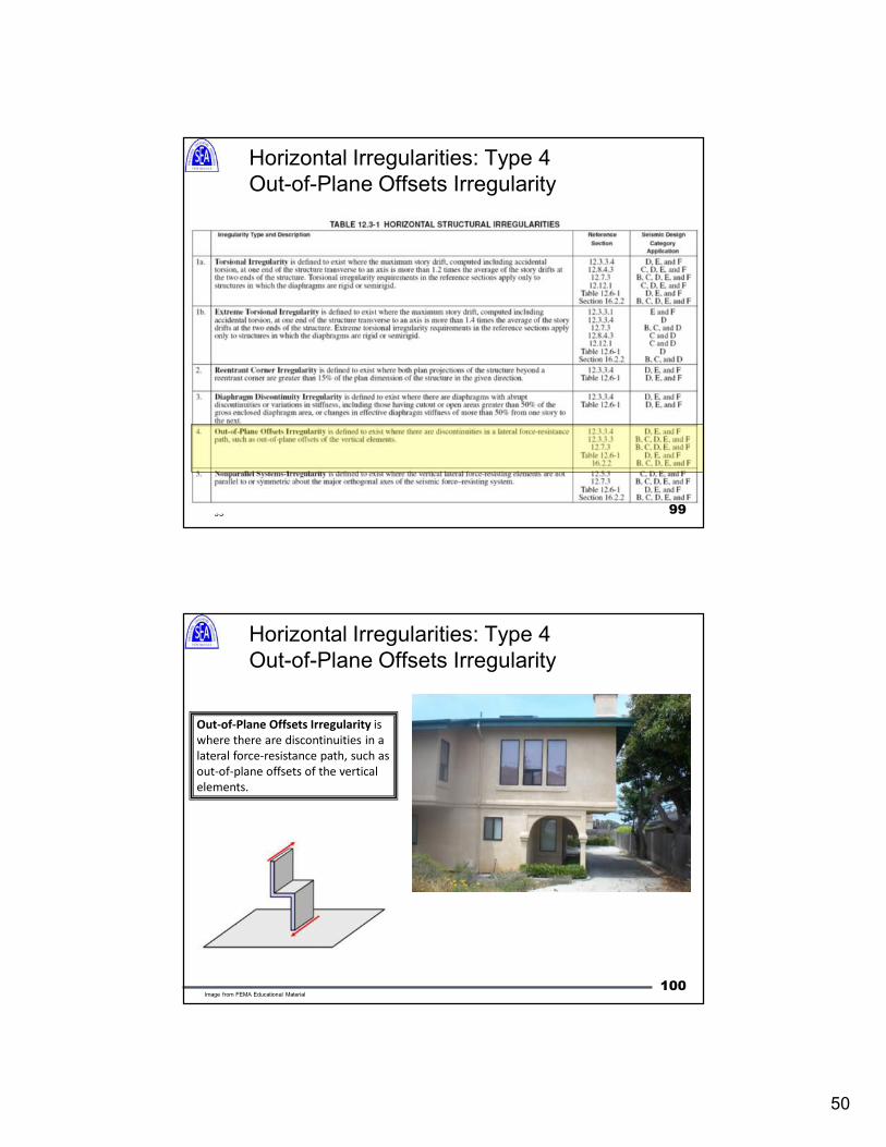
Question: If the roof diaphragm has an opening in
it which results in the stiffness of the 2nd floor
diaphragm being 50% stiffer than the roof, does
that make it irregular? The plan irregularity
definition says story-to-story.
Answer: Yes, it would be considered irregular…
doesn’t matter if floor or roof.
From ICC’s 2006 IBC
Q&A Manual:
98
50
99
Horizontal Irregularities: Type 4
Out-of-Plane Offsets Irregularity
99
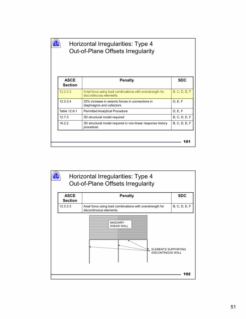
Horizontal Irregularities: Type 4
Out-of-Plane Offsets Irregularity
Out-of-Plane Offsets Irregularity is
where there are discontinuities in a
lateral force-resistance path, such as
out-of-plane offsets of the vertical
elements.
100Image from FEMA Educational Material
51
101
Horizontal Irregularities: Type 4
Out-of-Plane Offsets Irregularity
ASCE
Section
Penalty SDC
12.3.3.3 Axial force using load combinations with overstrength for
discontinuous elements.
B, C, D, E, F
12.3.3.4 25% increase in seismic forces in connections in
diaphragms and collectors
D, E, F
Table 12.6-1 Permitted Analytical Procedure D, E, F
12.7.3 3D structural model required B, C, D, E, F
16.2.2 3D structural model required in non-linear response history
procedure
B, C, D, E, F
Horizontal Irregularities: Type 4
Out-of-Plane Offsets Irregularity
ASCE
Section
Penalty SDC
12.3.3.3 Axial force using load combinations with overstrength for
discontinuous elements.
B, C, D, E, F
MASONRY
SHEAR WALL
ELEMENTS SUPPORTING
DISCONTINOUS WALL
102
52
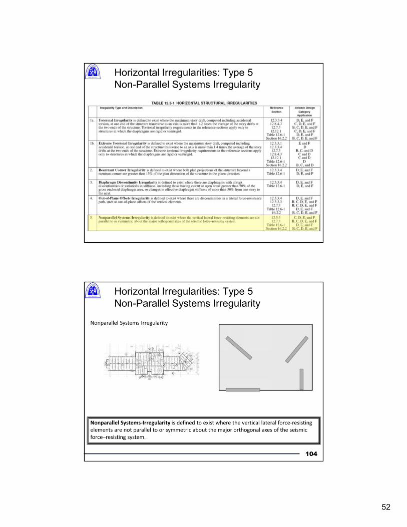
Horizontal Irregularities: Type 5
Non-Parallel Systems Irregularity
Horizontal Irregularities: Type 5
Non-Parallel Systems Irregularity
Nonparallel Systems Irregularity
Nonparallel Systems-Irregularity is defined to exist where the vertical lateral force-resisting
elements are not parallel to or symmetric about the major orthogonal axes of the seismic
force–resisting system.
104
53
105
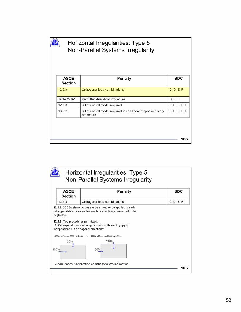
Horizontal Irregularities: Type 5
Non-Parallel Systems Irregularity
ASCE
Section
Penalty SDC
12.5.3 Orthogonal load combinations C, D, E, F
Table 12.6-1 Permitted Analytical Procedure D, E, F
12.7.3 3D structural model required B, C, D, E, F
16.2.2 3D structural model required in non-linear response history
procedure
B, C, D, E, F
106
Horizontal Irregularities: Type 5
Non-Parallel Systems Irregularity
ASCE
Section
Penalty SDC
12.5.3 Orthogonal load combinations C, D, E, F
12.5.3: Two procedures permitted:
1) Orthogonal combination procedure with loading applied
independently in orthogonal directions:
100% x-effects + 30% y-effects or 30% x-effects and 100% y-effects
2) Simultaneous application of orthogonal ground motion.
12.5.2: SDC B seismic forces are permitted to be applied in each
orthogonal directions and interaction effects are permitted to be
neglected.
54
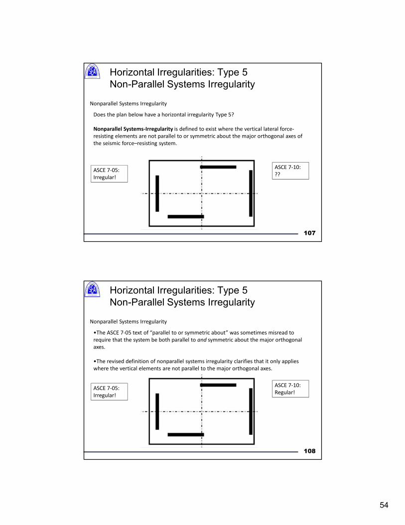
Horizontal Irregularities: Type 5
Non-Parallel Systems Irregularity
Nonparallel Systems Irregularity
Does the plan below have a horizontal irregularity Type 5?
Nonparallel Systems-Irregularity is defined to exist where the vertical lateral force-
resisting elements are not parallel to or symmetric about the major orthogonal axes of
the seismic force–resisting system.
ASCE 7-05:
Irregular!
ASCE 7-10:
??
107
Horizontal Irregularities: Type 5
Non-Parallel Systems Irregularity
Nonparallel Systems Irregularity
•The ASCE 7-05 text of “parallel to or symmetric about” was sometimes misread to
require that the system be both parallel to and symmetric about the major orthogonal
axes.
•The revised definition of nonparallel systems irregularity clarifies that it only applies
where the vertical elements are not parallel to the major orthogonal axes.
ASCE 7-05:
Irregular!
ASCE 7-10:
Regular!
108
55
Vertical Irregularities: Type 1a and 1b
Stiffness- Soft Story Irregularity
109
Vertical Irregularities: Type 1a and 1b
Stiffness- Soft Story Irregularity
Stiffness (Soft Story) Irregularity
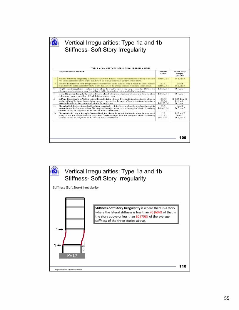
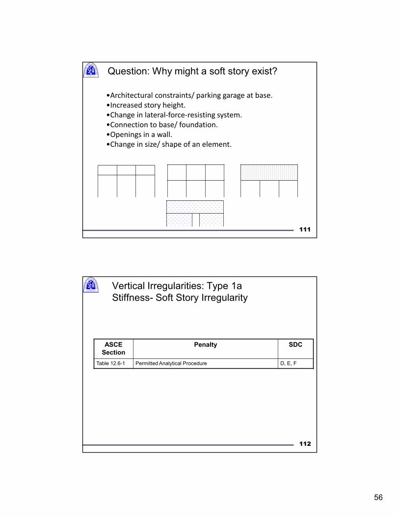
Stiffness-Soft Story Irregularity is where there is a story
where the lateral stiffness is less than 70 (60)% of that in
the story above or less than 80 (70)% of the average
stiffness of the three stories above.
110Image from FEMA Educational Material
56
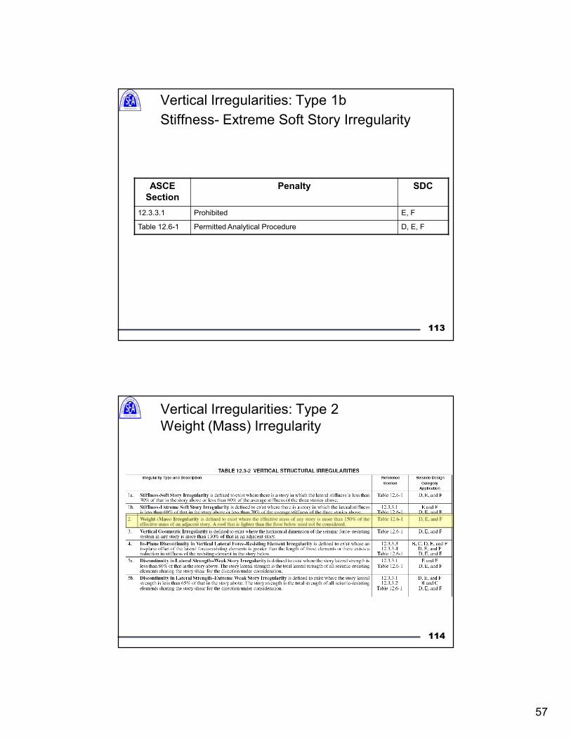
Question: Why might a soft story exist?
•Architectural constraints/ parking garage at base.
•Increased story height.
•Change in lateral-force-resisting system.
•Connection to base/ foundation.
•Openings in a wall.
•Change in size/ shape of an element.
111
112
Vertical Irregularities: Type 1a
Stiffness- Soft Story Irregularity
ASCE
Section
Penalty SDC
Table 12.6-1 Permitted Analytical Procedure D, E, F
57
113
Vertical Irregularities: Type 1b
Stiffness- Extreme Soft Story Irregularity
ASCE
Section
Penalty SDC
12.3.3.1 Prohibited E, F
Table 12.6-1 Permitted Analytical Procedure D, E, F
Vertical Irregularities: Type 2
Weight (Mass) Irregularity
114
58
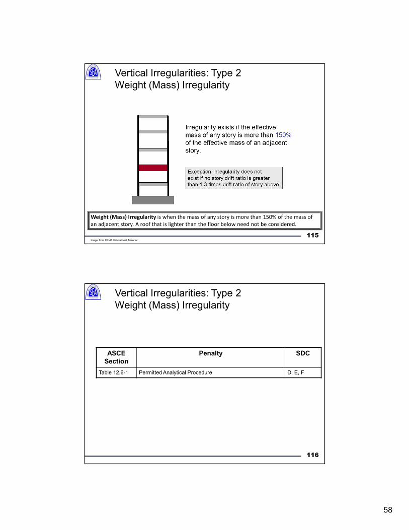
Weight (Mass) Irregularity is when the mass of any story is more than 150% of the mass of
an adjacent story. A roof that is lighter than the floor below need not be considered.
Vertical Irregularities: Type 2
Weight (Mass) Irregularity
115Image from FEMA Educational Material
116
ASCE
Section
Penalty SDC
Table 12.6-1 Permitted Analytical Procedure D, E, F
Vertical Irregularities: Type 2
Weight (Mass) Irregularity
59
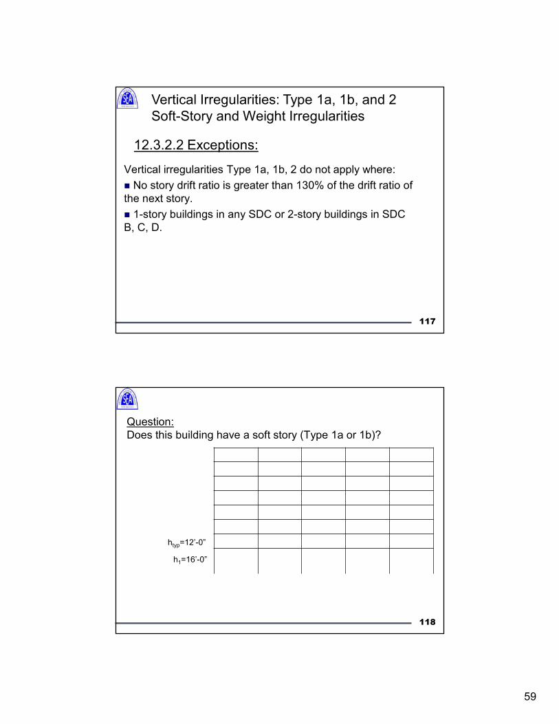
12.3.2.2 Exceptions:
Vertical irregularities Type 1a, 1b, 2 do not apply where:
No story drift ratio is greater than 130% of the drift ratio of
the next story.
1-story buildings in any SDC or 2-story buildings in SDC
B, C, D.
Vertical Irregularities: Type 1a, 1b, and 2
Soft-Story and Weight Irregularities
117
Question:
Does this building have a soft story (Type 1a or 1b)?
h1=16’-0”
htyp=12’-0”
118
60
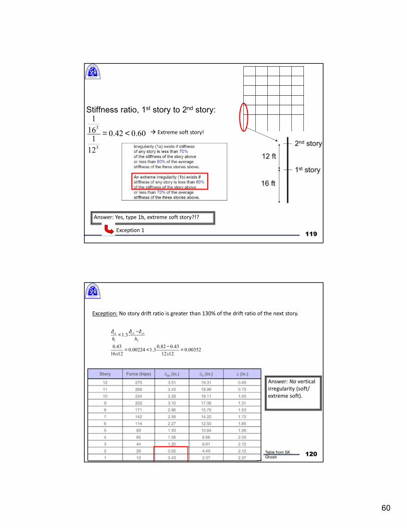
119
Stiffness ratio, 1st story to 2nd story:
60.042.0
12
1
16
1
3
3
<= Extreme soft story!
Answer: Yes, type 1b, extreme soft story?!?
Exception 1
120
Exception: No story drift ratio is greater than 130% of the drift ratio of the next story.
00352.01212
43.082.03.100224.0
1216
43.0
3.1
2
12
1
1
=−<=
−<
xx
hh
eeeδδδ
Answer: No vertical
irregularity (soft/
extreme soft).
Table from SK
Ghosh
61
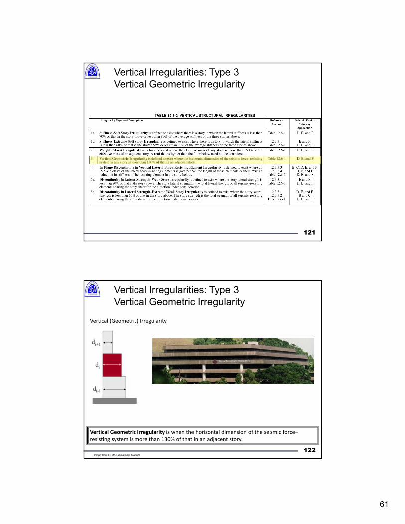
Vertical Irregularities: Type 3
Vertical Geometric Irregularity
121
Vertical (Geometric) Irregularity
Vertical Geometric Irregularity is when the horizontal dimension of the seismic force–
resisting system is more than 130% of that in an adjacent story.
Vertical Irregularities: Type 3
Vertical Geometric Irregularity
122Image from FEMA Educational Material
62
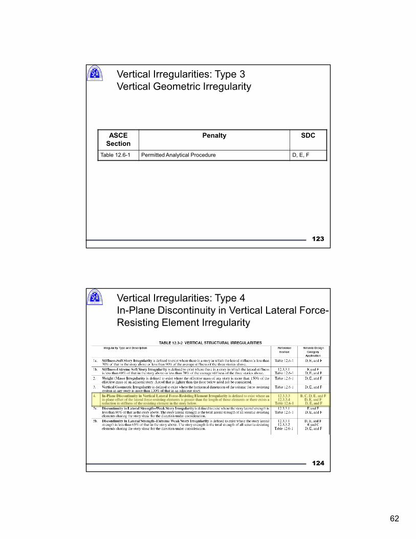
123
ASCE
Section
Penalty SDC
Table 12.6-1 Permitted Analytical Procedure D, E, F
Vertical Irregularities: Type 3
Vertical Geometric Irregularity
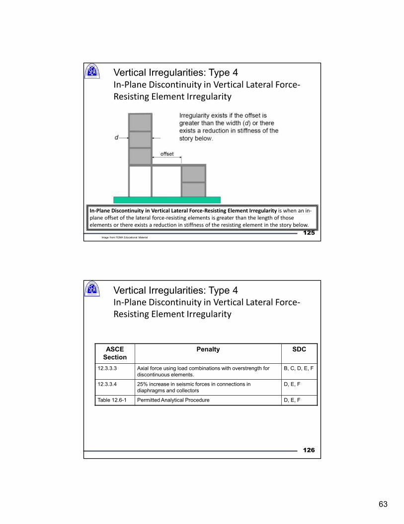
Vertical Irregularities: Type 4
In-Plane Discontinuity in Vertical Lateral Force-
Resisting Element Irregularity
124
63
In-Plane Discontinuity in Vertical Lateral Force-Resisting Element Irregularity is when an in-
plane offset of the lateral force-resisting elements is greater than the length of those
elements or there exists a reduction in stiffness of the resisting element in the story below.
Vertical Irregularities: Type 4
In-Plane Discontinuity in Vertical Lateral Force-
Resisting Element Irregularity
125Image from FEMA Educational Material
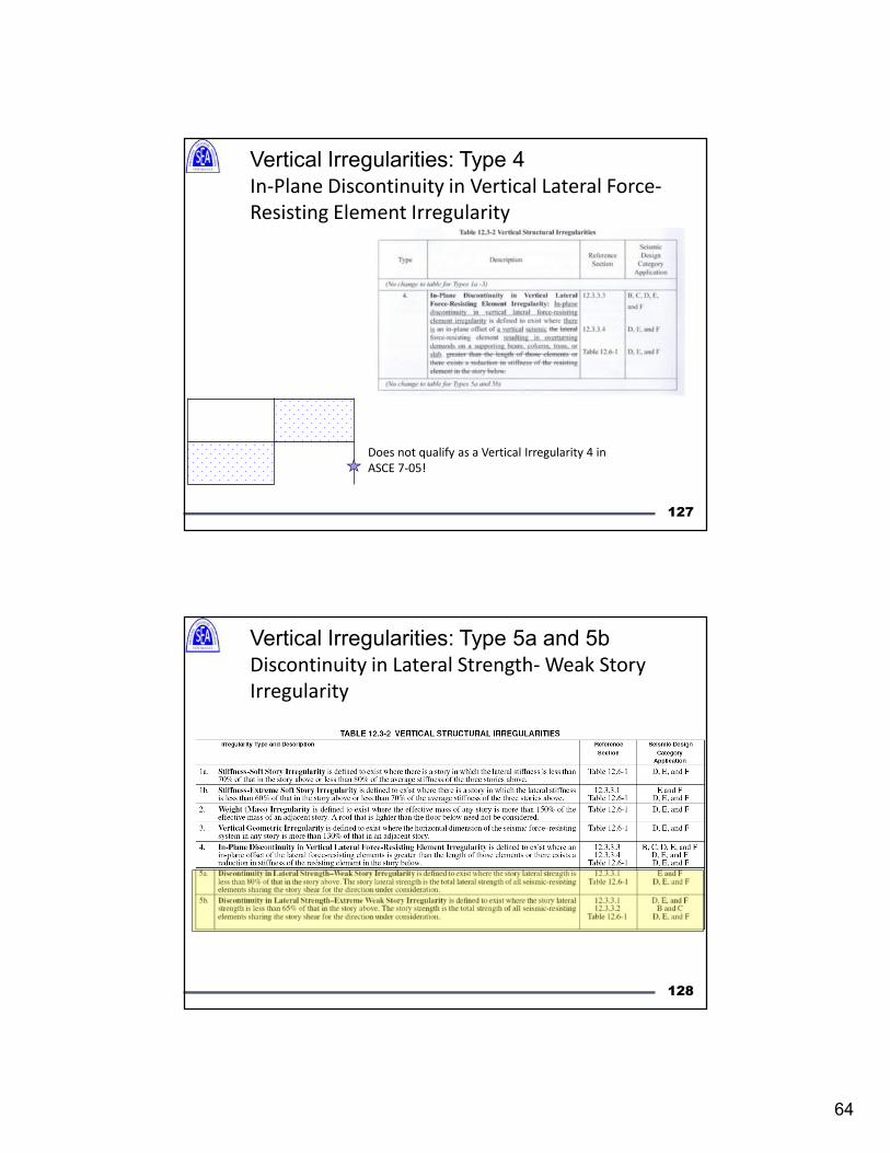
126
ASCE
Section
Penalty SDC
12.3.3.3 Axial force using load combinations with overstrength for
discontinuous elements.
B, C, D, E, F
12.3.3.4 25% increase in seismic forces in connections in
diaphragms and collectors
D, E, F
Table 12.6-1 Permitted Analytical Procedure D, E, F
Vertical Irregularities: Type 4In-Plane Discontinuity in Vertical Lateral Force-
Resisting Element Irregularity
64
Vertical Irregularities: Type 4
In-Plane Discontinuity in Vertical Lateral Force-
Resisting Element Irregularity
Does not qualify as a Vertical Irregularity 4 in
ASCE 7-05!
127
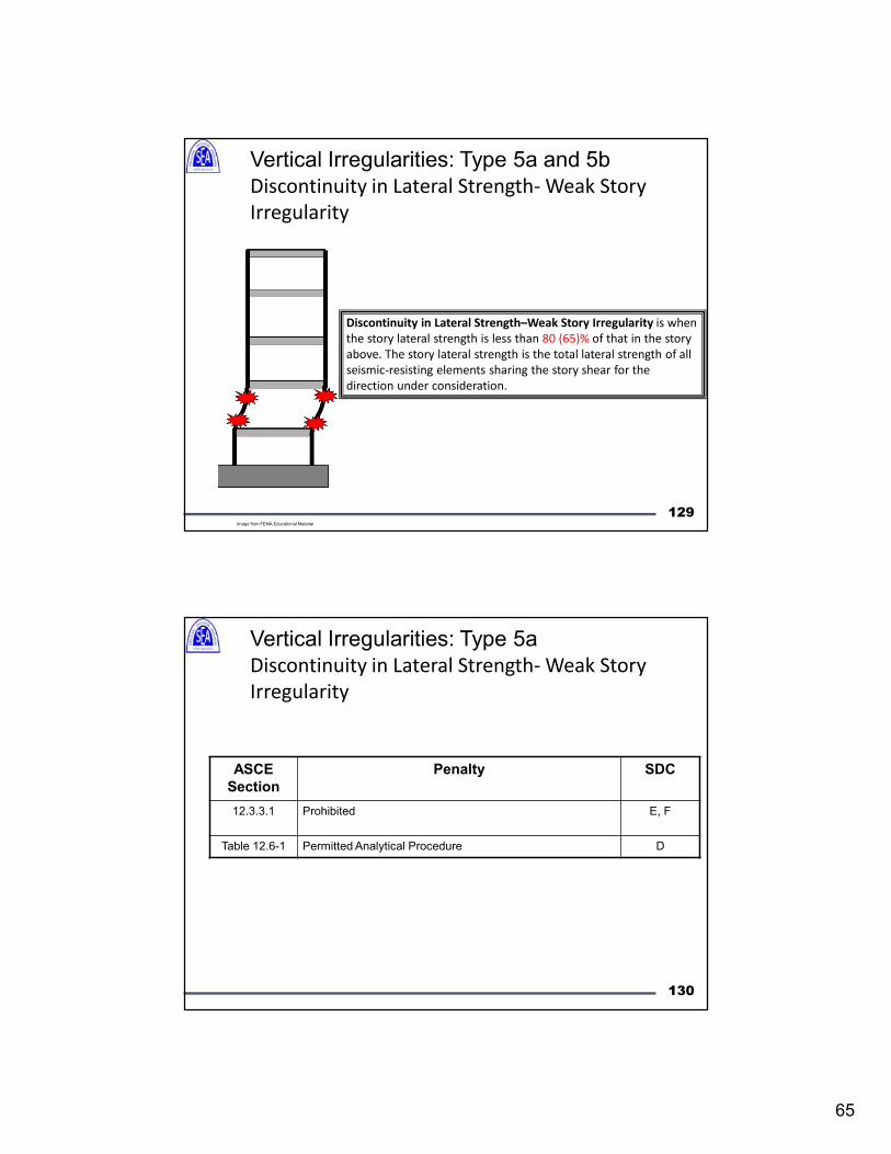
Vertical Irregularities: Type 5a and 5b
Discontinuity in Lateral Strength- Weak Story
Irregularity
128
65
Discontinuity in Lateral Strength–Weak Story Irregularity is when
the story lateral strength is less than 80 (65)% of that in the story
above. The story lateral strength is the total lateral strength of all
seismic-resisting elements sharing the story shear for the
direction under consideration.
Vertical Irregularities: Type 5a and 5b
Discontinuity in Lateral Strength- Weak Story
Irregularity
129Image from FEMA Educational Material
130
ASCE
Section
Penalty SDC
12.3.3.1 Prohibited E, F
Table 12.6-1 Permitted Analytical Procedure D
Vertical Irregularities: Type 5a
Discontinuity in Lateral Strength- Weak Story
Irregularity
66
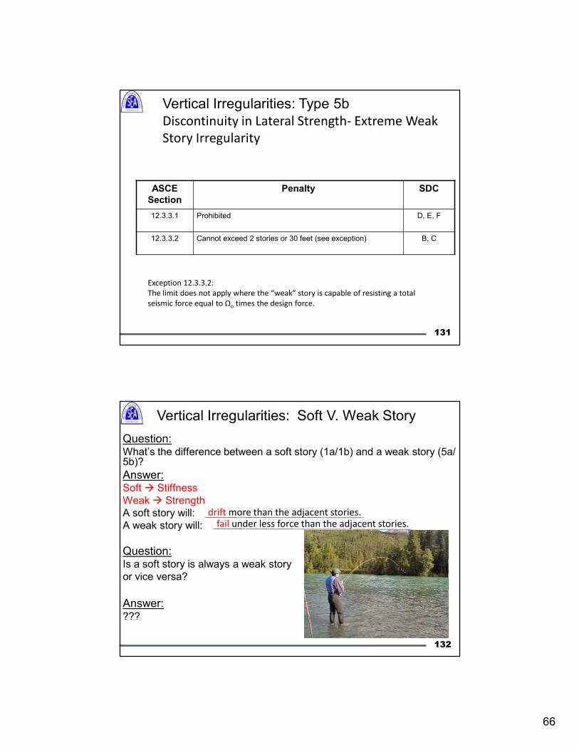
131
ASCE
Section
Penalty SDC
12.3.3.1 Prohibited D, E, F
12.3.3.2 Cannot exceed 2 stories or 30 feet (see exception) B, C
Exception 12.3.3.2:
The limit does not apply where the “weak” story is capable of resisting a total
seismic force equal to Ωo times the design force.
Vertical Irregularities: Type 5b
Discontinuity in Lateral Strength- Extreme Weak
Story Irregularity
Question:What’s the difference between a soft story (1a/1b) and a weak story (5a/ 5b)?
Answer:Soft Stiffness
Weak Strength
A soft story will:
A weak story will:
Question:Is a soft story is always a weak story
or vice versa?
Answer:???
fail under less force than the adjacent stories.drift more than the adjacent stories.
Vertical Irregularities: Soft V. Weak Story
132
67
Summary:
1) Understand the methodology built into the code values for R, Cd, Ωo.
2) The code attempts to steer engineers into redundant, ductile designs with
a linear load path.
3) Irregular structures routinely perform worse in seismic events, even when
properly detailed.
Emily Guglielmo
415-814-0030133