Embed Size (px)
Citation preview

Applied Ergonomics 32 (2001) 599–607
Comparison of measurement accuracy between two types of wristgoniometer systems
Per Jonssona,*, Peter W. Johnsonb
aSection of Occupational and Environmental Medicine, Sahlgrenska University Hospital, St. Sigfridsgatan 85, SE 412 66, Gothenburg, SwedenbDepartment of Environmental Health, University of Washington, Box 357234, Seattle, WA 98195, USA
Accepted 17 May 2001
Abstract
Studies have shown that wrist goniometers are prone to measurement errors, particularly due to crosstalk. This study comparedtwo wrist goniometer systems: a commonly used biaxial, single transducer (System A) and a biaxial, two-transducer (System B).Wrist angles, range of movement and crosstalk results were compared. With the wrist in 901 of pronation, eight subjects were placedin 20 different wrist postures between �401 and 401 of flexion/extension and between �101 and 201 of deviation.
Relative to System B, System A had larger measurement errors and was more prone to crosstalk. There may be two sources ofcrosstalk: (1) intrinsic crosstalk associated with the design, application and twisting of the goniometer transducer when on the wrist,and (2) extrinsic crosstalk associated with the anatomy and complex movement of the wrist joint. It appears that the majority of the
radial/ulnar crosstalk measured with System A was intrinsic crosstalk due to the twisting of the goniometer transducer. r 2001Elsevier Science Ltd. All rights reserved.
Keywords: Wrist; Goniometer and accuracy
1. Introduction
Extremes in wrist posture and repetitiveness are riskfactors for work related musculoskeletal disorders(WMSDs) (Silverstein et al., 1987; Marras and Schoen-marklin, 1993; St(aal et al., 1999). The WMSDs are amajor problem, which not only causes suffering for theindividual but also contributes to high costs for thesociety. It is important to prevent the occurrence ofthese disorders, especially since not even extensiverehabilitation programs may be successful (Hanssonand Mikkelsen, 1997).Awkward wrist postures have been found to be a
contributing risk factor for WMSDs of the hand andwrist, such as tendinitis, tenosynovitis, and carpal tunnelsyndrome (Hagberg et al., 1995). Since the introductionof electrogoniometers, the continuous collection andrecording of wrist postural data has been possible(Radwin and Lin, 1993; Hansson and Mikkelsen,1997; H.aagg et al., 1997; Ortiz et al., 1997; Strakeret al., 1997). Wrist postures can provide important
exposure information related to the postural risk factorsassociated with WMSDs.A goal of wrist posture measurements is to quantita-
tively record and verify wrist orientation. Accuracy andfidelity of wrist goniometers are essential for quantifyingexposure to potentially hazardous postures. A majorsource of error with the most widely used commerciallyavailable electrogoniometer is ‘‘crosstalk’’ (Hanssonet al., 1996; Buchholz and Wellman, 1997). Crosstalkoccurs when movement in one anatomical plane (e.g.flexion/extension) causes a false signal in the otheranatomical plane (e.g. radial/ulnar deviation). Crosstalkcan occur when the transducer of the goniometer is notlocated over the centres of movement for the joint(Moore et al., 1993) or when the strain gages inside theelectrogoniometer are twisted with respect to the move-ment planes of the wrist (Buchholz and Wellman, 1997).Previous studies when measuring wrist postures invarying degrees of pronation/supination have shownmean errors up to 51751 for flexion/extension (F/E) and61751 for radial/ulnar (R/U) deviation (Hansson et al.,1996; Buchholz and Wellman, 1997). Based on resultsfrom the most widely used commercially available*Corresponding author.
0003-6870/01/$ - see front matter r 2001 Elsevier Science Ltd. All rights reserved.
PII: S 0 0 0 3 - 6 8 7 0 ( 0 1 ) 0 0 0 3 6 - 9

electrogoniometer, an explicit equation for crosstalk as afunction of transducer twist has been derived byHansson et al., 1996.The purpose of this study was to compare the
measurement accuracy of a commonly used biaxial,single-transducer wrist goniometer to a wrist goniometerwith two separate biaxial transducers, over a wide rangeof F/E and R/U movements. Due to differences inhardware design and how the two goniometer systemsreside on the wrist, we hypothesise that there may bedifferences in the measurement accuracy between thetwo goniometer systems. These differences, if they exist,may have important implications for goniometer designand the accurate measurement and collection of wristangle data.
2. Methods
2.1. Subjects
Five women and three men (mean age=31, range 19–54) free of upper extremity musculoskeletal disorderswith no prior serious injuries to the wrist participated inthis study. All subjects were employees of the Occupa-tional and Environmental Medicine at SahlgenskaUniversity Hospital, Gothenburg, Sweden and volun-teered to participate in the study. Key anthropometricalparameters (hand length, palm length, wrist width, wristthickness, wrist circumference) were measured from thesubjects as prescribed by Garrett (1970a, b), andrecorded. Median and range are summarised in Table 1.
2.2. Equipment
Two wrist goniometer systems were evaluated(Fig. 1). The first system, designated as System A(Fig. 1, left), consisted of a single-transducer, biaxialgoniometer (Model X 65; Biometrics; Gwent, UK).System A was connected to an 8-bit data logger (ModelDL 1001; Biometrics; Gwent, UK) with an anglemeasurement resolution of 1.81. The second, System B(Fig. 1, middle), consisted of two biaxial transducersconnected to a 12-bit logger with an angle measurement
resolution of 0.11 (WristSystem; Greenleaf Medical;Palo Alto, CA). Goniometer System A was attached tothe subjects’ right wrist using the methods prescribed byBuchholz and Wellman (1997). System B was secured tothe subjects’ wrist using a lycra fingerless glove (Fig. 1,right). The glove came in three sizes; small, medium, andlarge; had three Velcro straps and was attached bysliding the glove and goniometer over the subject’s hand(Fig. 3, right). To secure the Velcro straps to the desiredtension, the experimenter put one finger under the gloveand tightened the straps over his/her finger. Thisensured that the glove was securely attached to thehand but loose enough around the wrist to allow theglove to rotate over the skin.Both systems used the same sensing element manu-
factured by Biometrics Ltd., Gwent, UK. The sensingelement consisted of a 0.3mm diameter steel beam(flexible wire) with four small resistive wires symme-trically mounted along the full length of the beam. Eachpair of diametrically opposed resistive wires formed acalibrated half-bridge strain gauge transducer. One pairof resistive wires was sensitive to flexion, the other todeviation. With System A, one end of the beam is fixedand anchored to one endblock. The other end of thebeam is connected to a second endblock, by means of atelescopic mechanism, and is allowed to slide, but notrotate within that endblock. Since both endblocks arerigidly secured to the hand and forearm with double-sided tape, any rotation between the two endblocks,which may occur during wrist movements, will betransmitted to the beam and potentially result inmeasurement errors. With System B, one end of thebeam is fixed and anchored to a distal endblock, whichis mounted over the back of the hand. The terminal endof the beam fits into a proximal endblock, which allows
Fig. 1. Wrist goniometers: System A transducer (left), System B
transducer (middle) and System B transducer and fingerless glove
(right).
Table 1
Summary measures in mm of key anthropometrical parameters
(N ¼ 8)
Parameter Median Range
Hand length 181 168–200
Palm length 103 92–119
Hand breath across thumb 95 90–117
Wrist width 59 52–67
Wrist thickness 39 34–46
Wrist circumference 157 147–196
P. Jonsson, P.W. Johnson / Applied Ergonomics 32 (2001) 599–607600
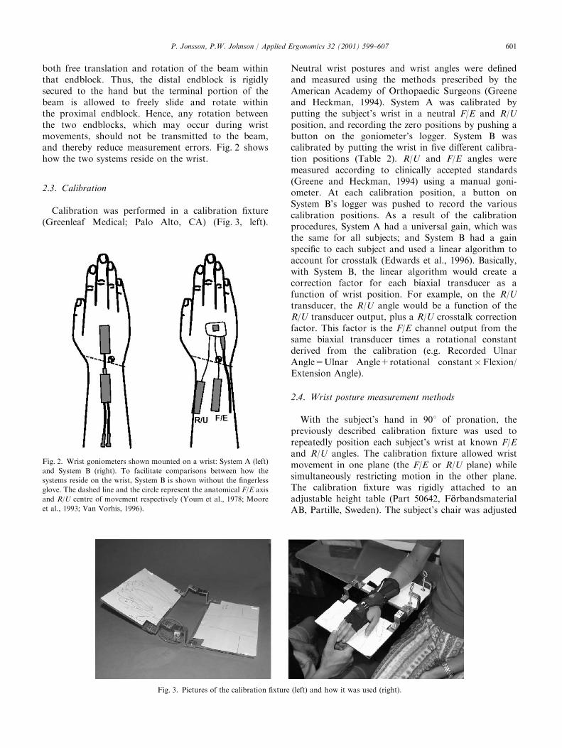
both free translation and rotation of the beam withinthat endblock. Thus, the distal endblock is rigidlysecured to the hand but the terminal portion of thebeam is allowed to freely slide and rotate withinthe proximal endblock. Hence, any rotation betweenthe two endblocks, which may occur during wristmovements, should not be transmitted to the beam,and thereby reduce measurement errors. Fig. 2 showshow the two systems reside on the wrist.
2.3. Calibration
Calibration was performed in a calibration fixture(Greenleaf Medical; Palo Alto, CA) (Fig. 3, left).
Neutral wrist postures and wrist angles were definedand measured using the methods prescribed by theAmerican Academy of Orthopaedic Surgeons (Greeneand Heckman, 1994). System A was calibrated byputting the subject’s wrist in a neutral F/E and R/Uposition, and recording the zero positions by pushing abutton on the goniometer’s logger. System B wascalibrated by putting the wrist in five different calibra-tion positions (Table 2). R/U and F/E angles weremeasured according to clinically accepted standards(Greene and Heckman, 1994) using a manual goni-ometer. At each calibration position, a button onSystem B’s logger was pushed to record the variouscalibration positions. As a result of the calibrationprocedures, System A had a universal gain, which wasthe same for all subjects; and System B had a gainspecific to each subject and used a linear algorithm toaccount for crosstalk (Edwards et al., 1996). Basically,with System B, the linear algorithm would create acorrection factor for each biaxial transducer as afunction of wrist position. For example, on the R/Utransducer, the R/U angle would be a function of theR/U transducer output, plus a R/U crosstalk correctionfactor. This factor is the F/E channel output from thesame biaxial transducer times a rotational constantderived from the calibration (e.g. Recorded UlnarAngle=Ulnar Angle+rotational constant�Flexion/Extension Angle).
2.4. Wrist posture measurement methods
With the subject’s hand in 901 of pronation, thepreviously described calibration fixture was used torepeatedly position each subject’s wrist at known F/Eand R/U angles. The calibration fixture allowed wristmovement in one plane (the F/E or R/U plane) whilesimultaneously restricting motion in the other plane.The calibration fixture was rigidly attached to anadjustable height table (Part 50642, F .oorbandsmaterialAB, Partille, Sweden). The subject’s chair was adjusted
Fig. 2. Wrist goniometers shown mounted on a wrist: System A (left)
and System B (right). To facilitate comparisons between how the
systems reside on the wrist, System B is shown without the fingerless
glove. The dashed line and the circle represent the anatomical F/E axis
and R/U centre of movement respectively (Youm et al., 1978; Moore
et al., 1993; Van Vorhis, 1996).
Fig. 3. Pictures of the calibration fixture (left) and how it was used (right).
P. Jonsson, P.W. Johnson / Applied Ergonomics 32 (2001) 599–607 601
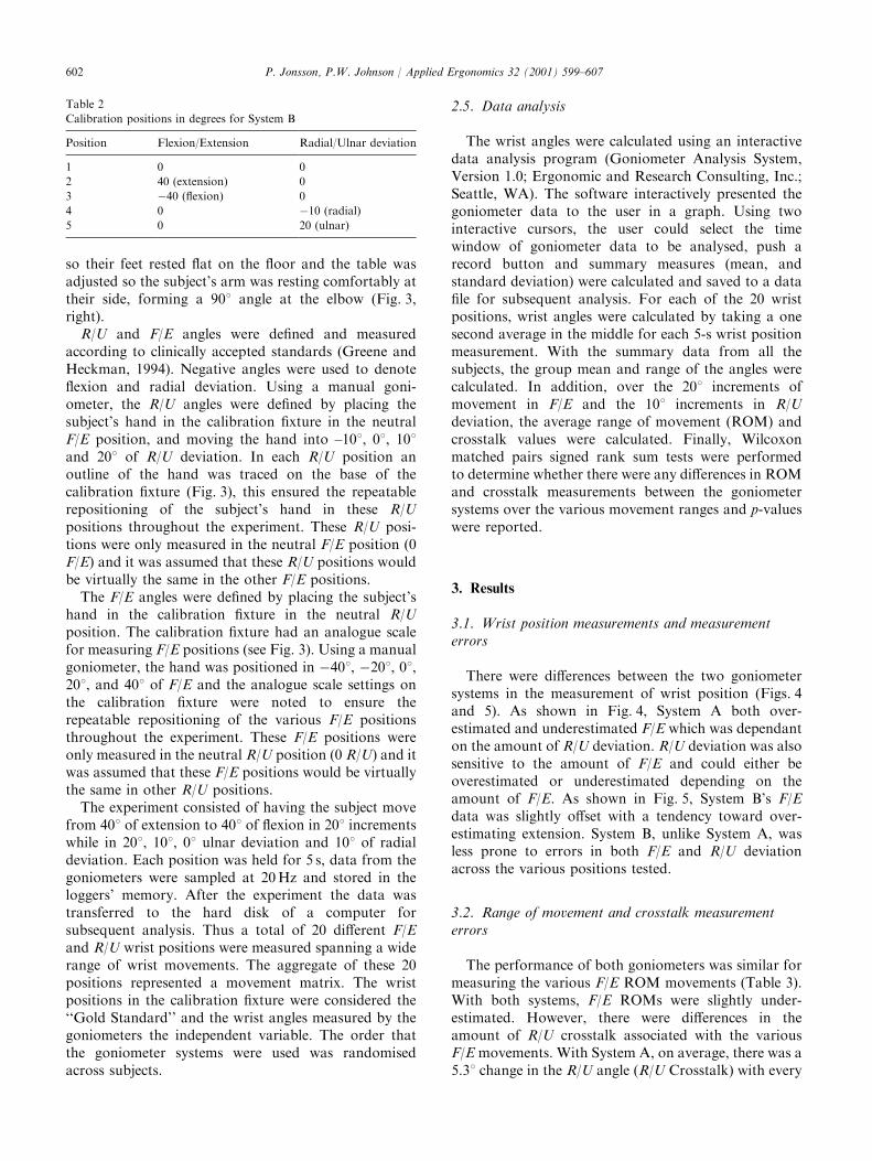
so their feet rested flat on the floor and the table wasadjusted so the subject’s arm was resting comfortably attheir side, forming a 901 angle at the elbow (Fig. 3,right).
R/U and F/E angles were defined and measuredaccording to clinically accepted standards (Greene andHeckman, 1994). Negative angles were used to denoteflexion and radial deviation. Using a manual goni-ometer, the R/U angles were defined by placing thesubject’s hand in the calibration fixture in the neutralF/E position, and moving the hand into –101, 01, 101and 201 of R/U deviation. In each R/U position anoutline of the hand was traced on the base of thecalibration fixture (Fig. 3), this ensured the repeatablerepositioning of the subject’s hand in these R/Upositions throughout the experiment. These R/U posi-tions were only measured in the neutral F/E position (0F/E) and it was assumed that these R/U positions wouldbe virtually the same in the other F/E positions.The F/E angles were defined by placing the subject’s
hand in the calibration fixture in the neutral R/Uposition. The calibration fixture had an analogue scalefor measuring F/E positions (see Fig. 3). Using a manualgoniometer, the hand was positioned in �401, �201, 01,201, and 401 of F/E and the analogue scale settings onthe calibration fixture were noted to ensure therepeatable repositioning of the various F/E positionsthroughout the experiment. These F/E positions wereonly measured in the neutral R/U position (0 R/U) and itwas assumed that these F/E positions would be virtuallythe same in other R/U positions.The experiment consisted of having the subject move
from 401 of extension to 401 of flexion in 201 incrementswhile in 201, 101, 01 ulnar deviation and 101 of radialdeviation. Each position was held for 5 s, data from thegoniometers were sampled at 20Hz and stored in theloggers’ memory. After the experiment the data wastransferred to the hard disk of a computer forsubsequent analysis. Thus a total of 20 different F/Eand R/U wrist positions were measured spanning a widerange of wrist movements. The aggregate of these 20positions represented a movement matrix. The wristpositions in the calibration fixture were considered the‘‘Gold Standard’’ and the wrist angles measured by thegoniometers the independent variable. The order thatthe goniometer systems were used was randomisedacross subjects.
2.5. Data analysis
The wrist angles were calculated using an interactivedata analysis program (Goniometer Analysis System,Version 1.0; Ergonomic and Research Consulting, Inc.;Seattle, WA). The software interactively presented thegoniometer data to the user in a graph. Using twointeractive cursors, the user could select the timewindow of goniometer data to be analysed, push arecord button and summary measures (mean, andstandard deviation) were calculated and saved to a datafile for subsequent analysis. For each of the 20 wristpositions, wrist angles were calculated by taking a onesecond average in the middle for each 5-s wrist positionmeasurement. With the summary data from all thesubjects, the group mean and range of the angles werecalculated. In addition, over the 201 increments ofmovement in F/E and the 101 increments in R/Udeviation, the average range of movement (ROM) andcrosstalk values were calculated. Finally, Wilcoxonmatched pairs signed rank sum tests were performedto determine whether there were any differences in ROMand crosstalk measurements between the goniometersystems over the various movement ranges and p-valueswere reported.
3. Results
3.1. Wrist position measurements and measurementerrors
There were differences between the two goniometersystems in the measurement of wrist position (Figs. 4and 5). As shown in Fig. 4, System A both over-estimated and underestimated F/E which was dependanton the amount of R/U deviation. R/U deviation was alsosensitive to the amount of F/E and could either beoverestimated or underestimated depending on theamount of F/E. As shown in Fig. 5, System B’s F/Edata was slightly offset with a tendency toward over-estimating extension. System B, unlike System A, wasless prone to errors in both F/E and R/U deviationacross the various positions tested.
3.2. Range of movement and crosstalk measurementerrors
The performance of both goniometers was similar formeasuring the various F/E ROM movements (Table 3).With both systems, F/E ROMs were slightly under-estimated. However, there were differences in theamount of R/U crosstalk associated with the variousF/Emovements. With System A, on average, there was a5.31 change in the R/U angle (R/U Crosstalk) with every
Table 2
Calibration positions in degrees for System B
Position Flexion/Extension Radial/Ulnar deviation
1 0 0
2 40 (extension) 0
3 �40 (flexion) 0
4 0 �10 (radial)
5 0 20 (ulnar)
P. Jonsson, P.W. Johnson / Applied Ergonomics 32 (2001) 599–607602

201 of F/E; with System B, the change in R/U angles wasless, averaging 0.71.Both systems performed similarly in measuring the
R/U ROM movements. In general, the R/U ROMsmeasured by the goniometers were similar and under-estimated (Table 4). For the eight subjects the upper andlower limits of the ROM movements were less withSystem B. Slight differences existed in the amount of F/Ecrosstalk with respect to the various R/U movements.With System A, on average there was a 2.81 change inthe F/E angle (F/E crosstalk) with every 101 of R/Udeviation; with System B, the change in F/E angles wasless, averaging 0.61.
4. Discussion
Evaluation of wrist posture can be facilitated by usingeither of the goniometer systems but knowing thelimitations of each system will be important in thecontext of interpreting results. In addition, someadditional standardization in the use of goniometerswould facilitate comparisons within and between studieswhen different methods or equipment are used. Forexample, how neutral wrist positions are defined and the
pronation/supination position chosen to calibrate/zerothe goniometers are important considerations whencomparing results.
4.1. Measurement accuracy and crosstalk differencesbetween goniometer systems
With System A, the trends in the differences from the‘‘Gold Standard’’ were similar to the results shown inBuchholz and Wellman (1997); however, the R/Ucrosstalk was greater in our study. A one-to-onecomparison of System A’s results to that of Buchholzand Wellman (1997) is difficult due to the use of adifferent sized goniometer and different calibrationposture. There was more R/U crosstalk with System Aand substantially less crosstalk with System B. Theremay be two sources of crosstalk: (1) intrinsic crosstalkassociated with the design, application and twisting ofthe goniometer transducer when on the wrist, and (2)extrinsic crosstalk associated with the anatomy andcomplex movement of the wrist joint. Based on theresults from Hansson et al. (1996), it appears that themajority of the R/U crosstalk measured with System Awas intrinsic crosstalk due to the twisting of thegoniometer transducer.
Fig. 5. Movement Matrixes, System B. Figures show the results for the
20 different wrist positions tested relative to the Gold Standard (e.g.
actual wrist positions controlled by calibration fixture).
Fig. 4. Movement Matrixes, System A. Figures show the results for
the 20 different wrist positions tested relative to the Gold Standard
(e.g. actual wrist positions controlled by calibration fixture).
P. Jonsson, P.W. Johnson / Applied Ergonomics 32 (2001) 599–607 603

Finally, with System A, crosstalk has been shown tobe dependant on the amount of pronation/supinationwith the crosstalk at a maximum in full pronation; neara minimum in the neutral position; and then increasingto a maximum, but in the opposite direction, in fullsupination (Hansson et al., 1996; Buchholz and Well-man, 1997). Our experiment was carried out near fullpronation and could be considered to represent oneextreme as far as crosstalk results with System A areconcerned. Additionally, the fact that the calibrationfixture used to position the wrist in the experiments wasalso used to calibrate System B could have favourablybiased System B’s results. However, rather than a biasthis may be an inherent advantage with System B. Thepurpose of System B’s calibration routine was tomeasure, account and correct for crosstalk. This wasclearly demonstrated in the results. However, System B’s
calibration routine may only optimised for the prona-tion/supination posture used in the calibration. In orderto better understand the impact of the calibrationroutine, other pronation/supination positions need tobe tested.
4.2. ROM measurement differences between goniometersystems
As shown by the range measurements in Tables 3 and4, System B tended to yield less between-subjectdifferences with respect to R/U measures. Both systemsunderestimated the ROM for F/E and R/U movements.Tables 3 and 4 demonstrate that the magnitude of themovements were consistent between goniometers andbetween movement ranges (201 of F/E and 101 of R/Udeviation), this indicates that our procedures were
Table 3
Measured ROM in flexion/extension and corresponding radial/ulnar crosstalka
Movement ROM Measured ROM Radial/Ulnar crosstalk
System A System B p-value System A System B p-value
�401 to �201 Flexion 20 18.5 19.7 0.18 �5.7 0.3 0.0009
(14.4–24.3) (14.8–23.0) (�7.3 to �3.6) (�3.2�3.1)
�20 to 01 Flexion 20 18.7 20.9 0.27 �5.3 �0.4 0.0009
(15.3–22.5) (16.8–25.8) (-9.0 to �1.8) (�1.6–0.5)
0 to 201 Extension 20 19.2 17.9 0.31 �4.9 �0.8 0.001
(15.75–25.2) (12.2–25.1) (�9.0 to �1.8) (�3.2–0.4)
20 to 401 Extension 20 19.6 19.3 0.87 �5.2 �1.1 0.03
(10.8–25.2) (11.0–23.2) (�11.7–0.0) (�6.7–1.7)
�40 to 401 Full ROM 80 76.0 77.8 0.56 �21.0 �2.0 0.0009
(68.4–84.6) (72.5–82.8) (�33.3 to �9.0) (�6.0–1.7)
aMean and (ranges) in degrees shown in table. Negative radial/ulnar crosstalk values indicate a false radial deviation signal, positive values a false
ulnar deviation signal.
Table 4
Measured ROM in radial/ulnar deviation and corresponding flexion/extension crosstalka
Movement ROM Measured ROM Flexion/Extension crosstalk
System A System B p-value System A System B p-value
�10 to 01 Radial 10 8.4 7.8 0.87 0.5 �1.5 0.04
(3.6–15.3) (4.7–13.6) (�1.8–3.6) (�3.0–0.8)
0 to 101 Ulnar 10 8.1 8.7 0.63 1.5 0.3 0.31
(4.5–15.3) (6.2–13.7) (�1.8–5.4) (�3.6–6.5)
10 to 201 Ulnar 10 9.0 8.6 0.43 6.3 �0.1 0.005
(2.7–12.6) (5.2–10.1) (0.0–10.8) (�2.4–3.1)
�10 to 201 Full ROM 30 25.6 25.1 0.63 8.2 �1.2 0.01
(16.2–34.0) (21.6–31.7) (�3.6–13.5) (�7.3–2.8)
aMean and (ranges) in degrees shown in table. Negative flexion/extension crosstalk values indicate a false flexion signal, positive values a false
extension signal.
P. Jonsson, P.W. Johnson / Applied Ergonomics 32 (2001) 599–607604

relatively consistent within and between goniometers.The underestimation of the R/U movements could be aresult of our methods. Subjects could subtlety move thedistal end of their forearm side-to-side to partiallycompensate for some of the R/U movement. Movementof the transducers, glove (System B) or the skin relativeto the underlying bones and joints may have contributedto the underestimation of the ROMs measured. It is alsoworth noting that with System B there was a compres-sion of the R/U ROM when going from extension toflexion (Fig. 5).
4.3. Design differences between goniometer systems
System A has a resolution of 1.81 and system Bhas 0.11. If measurements were made on just oneindividual, then this difference in resolution wouldhave an impact when comparing individual results.However, since the measurements and means werecalculated on eight subjects, this provided System Awith an effective resolution of up to 0.21. Thus we feelthe differences in resolution were not important to thedifferences observed between goniometer systems in thisstudy.The single-transducer used with System A was firmly
attached with double-sided tape to the hand andforearm and could not be moved after the transducerhad been zeroed. Subsequently, if the end blocks of thetransducer were twisted due to wrist movement, cross-talk could occur (Hansson et al., 1996. Buchholz andWellman, 1997). With System B, the proximal ends ofthe transducers floated freely within the proximal endblocks, this allowed the end blocks to twist withoutimparting any twist on the transducers. Based on theknown relationship between goniometer twist andcrosstalk (Hansson et al., 1996), we feel the twistreducing design of System B may be a major factorbehind the differences in R/U crosstalk between thesystems. Fig. 6 shows the individual differences in R/Ucrosstalk, grouped by goniometer, over the full ROM inF/E when the wrist was in 01 R/U. We feel thedifferences in means between goniometer systems onleft side of Fig. 6 may be a function of the differences inthe amount of transducer twist. Another differencebetween the two systems was System B employed a 5-point calibration and a linear algorithm, based on wristangle, to ‘‘electronically align’’, correct and compensatefor crosstalk as described under Section 2.3 in theMethods. Therefore, besides the twist reducing design,we feel the linear alignment algorithm derived from thefive-point calibration can measure and correct for someremaining misalignment/twist in the transducer, therebytaking individual differences into account. We feel thisdifference between systems is represented by thedifferences in individual variation (standard deviation)on right side of Fig. 6.
Moreover, System A had a single transducer formeasuring wrist angles whereas System B employed twotransducers. Due to using the same transducer formeasuring both F/E and R/U deviation, the design ofSystem A assumes the axes for F/E and R/U deviationare orthogonal and intersect one another. However,there is evidence that the wrist has two, non-orthogonal,non-intersecting axes of movement (Youm and Yoon,1979; Moore et al., 1993; Van Vorhis, 1996). Oneimplication for System A is, if goniometer twist waspresent and somehow optimised relative to one move-ment axis, this optimisation may not apply or could bedetrimental to the other movement axis. System B andits two-transducer design attempts to locate the trans-ducers over and orthogonal to the two different move-ment axes, thereby making the transducer optimisationindependent, and potentially reducing crosstalk andmeasurement errors associated with transducer place-ment. This could also explain some of the observeddifferences in performance between systems.In summary, it appears the goniometer design, the
linear alignment algorithm employed with System Band transducer placement are all possible explanationsfor the observed differences between goniometersystems. However, since only one pronation/supina-tion posture was investigated in this study, it is notpossible to determine conclusively the relative influenceof each.
4.4. Implications, limitations and future studies
Future directed work is needed to systematicallyassess the impact of the various design differences
Fig. 6. Individual comparison of R/U Crosstalk between System A
and B over the full range of F/E in 0 R/U grouped by subject. The
mean difference between systems is shown on the left, and using the
group standard deviation, individual differences within systems are
shown on the right.
P. Jonsson, P.W. Johnson / Applied Ergonomics 32 (2001) 599–607 605
between the goniometer systems. With System A theR/U measurement errors were consistent (linear) acrossthe full F/E ranges of motion tested in this study(Fig. 4). Since the lines in the movement matrix wereparallel, it appears that the R/U crosstalk with System Acould be corrected for using the same crosstalkalgorithm employed by System B; however, twoseparate transducers would be necessary. On the otherhand, the F/E crosstalk with System A was notconsistent across R/U deviation (non-linear) and theerror may be a mechanical artefact resulting from theforearm or wrist lumen changing size, the placement ofthe transducer relative to the anatomical axes/centres ofmovement or a combination of both.Other important aspects to consider include the
calibration postures and the fact that slight, almostundetectable movements during calibration can sub-stantially affect the offsets of Systems A and B. Thedefinition of the ‘‘zero/reference’’ position is critical forcomparisons between studies. We used the positionsrecommended by American Academy of OrthopaedicSurgeons (Greene and Heckman, 1994). For F/E, theneutral (reference) position was defined by the positionwhen the plane of the back of the hand was in line withthe plane on the dorsal surface of the forearm. If the F/Ereference position was defined as the posture assumedwhen the forearm was resting flat on the work surfaceand the hand pressed flat, anecdotally we observedtypically at least a 71 difference between the tworeference positions. In addition, our experience frompositioning the wrist in the calibration fixture was that itwas hard to visually repeat postures better than741 andthe subtle difference between having the fingers relaxed(slightly curled) versus the fingers flat in the calibrationfixture can affect F/E wrist angle by as much as 101.We did not measure thermally related signal drift, but
this should be accounted for when using electrogoni-ometers. Temperature stability provided by the manu-facturer is 0.0671/1C. As a standard practice, we turnedthe goniometers on at least 10min before putting themon the subjects to allow them to thermally stabilize forheating due to electrical current. Although not practisedin this study, it would be beneficial to apply thegoniometers and let them sit on the subjects andthermally stabilise, for heating from body tissue, for atleast 10min before calibrating the goniometers.Finally, there were some limitations in this study.
First, since we did not test the goniometers over the fullrange of F/E, possible measurement errors associatedwith extreme F/E were not characterised or identified. Inaddition, we only tested the goniometers in onepronation/supination position. This study demonstratedthat goniometers are sensitive and subject to measure-ment errors due to simple F/E and R/U movements;therefore, since the wrists are used in varying degrees ofpronation/supination, we feel it would be worthwhile to
characterise and quantify the measurement errorsassociated with pronation/supination.
Acknowledgements
The authors wish to thank Alexander Areskoug,National Institute for Working Life, G .ooteborg, Sweden,for his contribution in very carefully performing themeasurements, the staff of the Section of Occupationaland Environmental Medicine who patiently acted as testsubjects for and professor Mats Hagberg, SahlgrenskaUniversity Hospital, who financially supported thestudy.
References
Buchholz, B., Wellman, H., 1997. Practical operation of a biaxial
goniometer at the wrist joint. Hum. Factors 39 (1), 119–129.
Edwards, G.L., Rothenberg, S.J., Oberman, M.L., 1996. Electronically
aligned man–machine interface. United States Patent. Patent
Number 5,533,531. Date of patent July 9, 5–6.
Garrett, J.W., 1970a. Anthropometry of the hand of female air force
flight personnel (Report AMRL-TR-69-26). Wright-Patterson Air
Force Base. OH: Air Form Systems Command. Aerospace Medical
Division, Aerospace Medical Research Laboratory.
Garrett, J.W., 1970b. Anthropometry of the hand of male air force
flight personnel (Report AMRL-TR-69-42). Wright Patterson Air
Force Base. OH: Air Form Systems Command. Aerospace Medical
Division. Aerospace Medical Research Laboratory.
Greene, W.B., Heckman, J.D., 1994. The Clinical Measurement of
Joint Motion. American Academy of Orthopaedic Surgeons,
Rosemont, IL, USA.
Hagberg, M., Silverstein, B., Wells, R., Smith, R., Carayon, P.,
Hendrick, H., Perusse, M., Kourinka, I., Forcier, L. (Eds.). Work-
related Musculoskeletal Disorders (WMSD): A Reference Book for
Prevention. Taylor & Francis, London, 1995.
H.aagg, G.M., .OOster, J., Bystr .oom, S., 1997. Forearm muscular load and
wrist angle among automobile assembly line workers in relation to
symptoms. Appl. Ergon. 28 (1), 41–47.
Hansson, G. (AA., Mikkelsen, S., 1997. Kinematic evaluation of
occupational work. Adv. Occup. Med. Rehab.. 3, 57–69.
Hansson, G. (AA, Balogh, I., Ohlsson, K., Rylander, L., Skerfving, S.,
1996. Goniometer measurement and computer analysis of wrist
angles and movements applied to occupational repetitive work. J.
Electromyogr. Kinesiol. 6 (1), 23–35.
Marras, W.S., Schoenmarklin, R.W., 1993. Wrist motions in industry.
Ergonomics 36 (4), 341–351.
Moore, J.A., Small, C.F., Bryant, J.T., Ellis, R.E., Pichora, D.R.,
Hollister, A.M., 1993. A kinematic technique for describing wrist
joint motion: analysis of configuration space plots. Proc. Inst.
Mech. Eng. [H]. 207 (4), 211–218.
Ortiz, D.J., Marcus, M., Gerr, F., Jones, W., Cohen, S., 1997.
Measurement variability in upper extremity posture among VDT
users. Appl. Ergon. 28 (2), 139–143.
Radwin, R.G., Lin, M.L., 1993. An analytical method for characteriz-
ing repetitive motion and postural stress using spectral analysis.
Ergonomics 36 (4), 379–389.
Silverstein, B.A., Fine, L.J., Armstrong, T.J., 1987. Occupational fac-
tors and carpal tunnel syndrome. Am. J. Ind. Med. 11 (3), 343–358.
P. Jonsson, P.W. Johnson / Applied Ergonomics 32 (2001) 599–607606

St(aal, M., Hansson, G. (AA., Moritz, U., 1999. Wrist positions and
movements as possible risk factors during machine milking. Appl.
Ergon. 30 (6), 527–533.
Straker, L., Jones, K.J., Miller, J., 1997. A comparison of the postures
assumed when using laptop computers and desktop computers.
Appl. Ergon. 28, 263–268.
Van Vorhis, R., 1996. Kinematic measurements about wrist functional
anatomic axis-validation of mechanical wrist phantom for ergo-
nomic motion studies. In: Van Vorhiz, R. Mollister,
A., Mollerbach, K., Tittiramonda, P., Burastero, S. (Eds.), Risk
Assessment for Musculoskeletal Disorders. Nordic Satellite Sym-
posium under the auspices of ICOH ’96. National Institute of
occupational Health, Denmark, pp. 57–60.
Youm, Y., Yoon, Y.S., 1979. Analytical development in investigation
of wrist kinematics. J Biomech. 12 (8), 613–621.
Youm, Y., McMurthy, R.Y., Flatt, A.E., Gillespie, T.E., 1978.
Kinematics of the wrist. I. An experimental study of radial-ulnar
deviation and flexion-extension. J. Bone Jt. Surg. Am. 60 (4),
423–431.
P. Jonsson, P.W. Johnson / Applied Ergonomics 32 (2001) 599–607 607