Embed Size (px)
Citation preview
*E-Mail: [email protected]
Comparison and Selection of Construction Schemes for Cast-in-Situ girders of a Continuous Rigid-Frame Bridge
Bo Zhu1,8
1Key Laboratory for Bridge and Tunnel of Shanxi Province, Chang’an University, Xi’an, China, 710064; PH(+86):18023721319;
Abstract. The continuous rigid frame bridge is one of the main bridge types used to span rivers in mountainous areas due to its high rigidity. However, due to the poor geological conditions in mountainous areas, the probability of instability and other safety accidents increases. Therefore, strict construction scheme design must be carried out. According to the cast-in-place section of the side span of a continuous rigid frame bridge in a mountainous area, this paper puts forward three construction schemes that may be applicable. The finite element software is used to establish the model, and the girder stress and bridge alignment with different construction schemes are analyzed. Combined with the grading index evaluation method, the optimal construction scheme is finally obtained.
1 Introduction
Long span continuous rigid frame bridge has the advantages of large stiffness and good seismic performance. It is one of the main bridge types crossing deep ditches and rivers. However, due to the influence of the construction site environment and other factors, the safety risk in the process of bridge construction increases, so the relevant technical personnel need to pay enough attention to it.
When the side span girders are located in steep terrain, if the conventional floor support cast-in-place construction scheme is adopted, the height of the support required is too high. Moreover, the pier foundations are located on the steep slope, so the construction is difficult, and the economy and safety are poor[1-3].
In view of the construction difficulties of side span cast-in-place girders under the condition of steep terrain, this paper proposes three construction schemes referring to the construction experience of similar bridges[4-8]. The finite element model is established for stress analysis, and the schemes are compared and selected according to the applicability, economy and other indicators. The results show that scheme 2 is reasonable and economical.
2 Comparison and selection method of construction schemes based on grading indexes
2.1 Weight of grading indexes
In the process of scheme comparison and selection, it is necessary to determine the weight of evaluation indexes at
all levels. The slight change of the weight will have a significant impact on the selection results, and the unreasonable determination of the index weight at all levels will lead to the distortion of the optimal scheme. In order to reduce the influence of subjective factors and improve the effectiveness, this paper uses the analytic hierarchy process (AHP) to scientifically and methodically calculate the weight of indicators at all grades[9, 10]. The calculation steps are as follows: Establish a hierarchical structure of multi-level
indicators, and clarify the relationship between each grade;
Perform pairwise comparisons of indicators at the same grade to establish a comparison matrixA ;
Calculate the ranking index ,ci j of each
indicator, and construct a judgment matrix C ;
Find the maximum eigenvalue max , and check
the consistency; The test coefficient should satisfy
. . ( 0.001)C IP , and then calculate the
index weights at all levels.
2.2 Optimal construction scheme
Select the first-grade indicators that reflect the performance of the design plan, and use the analytic hierarchy process to calculate the weights of the indicators:
1
1n
iW (1)
© The Authors, published by EDP Sciences. This is an open access article distributed under the terms of the Creative Commons Attribution License 4.0
(http://creativecommons.org/licenses/by/4.0/).
E3S Web of Conferences 272, 02002 (2021) https://doi.org/10.1051/e3sconf/202127202002ICEPG 2021
Where: n is the number of indicators, W ( = ~ )i i n1
is the weight of the i-th indicator.
1 2 3[ ]TnW W W W W
(2)
The index score matrix is as follows:
1,1 1,
,
,1 ,
n
i i
m m n
a a
A a
a a
(3)
The scheme score vector is as follows:
1 2 3[ ]W= T
mS S S SS A
(4)
The element ( 1 ~ )jS j m in the score vector S
represents the final score of each scheme, and the
maximum value Max jS corresponds to the optimal
solution.
3 Case study
3.1 Project Overview
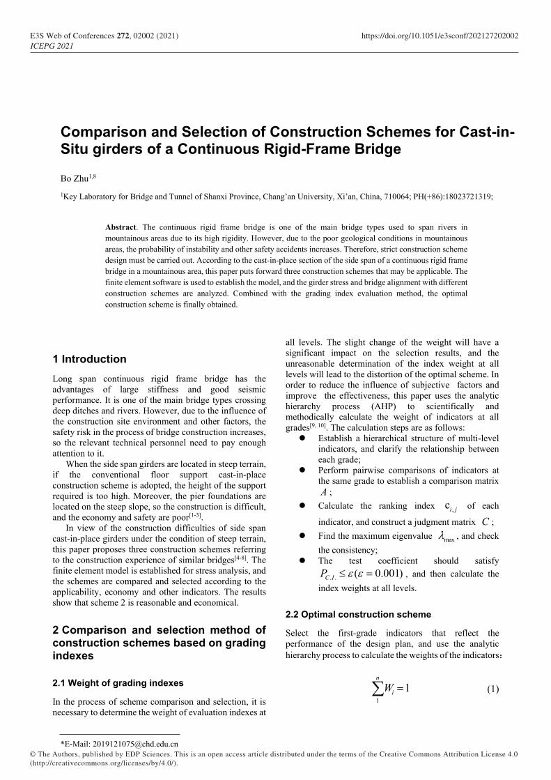
A prestressed concrete continuous rigid frame bridge is located in the mountain valley terrain, and the overall layout is shown in Figure 1. The main beam adopts single-box and double-chamber variable cross-section. The top plate is 16.5 meters wide, the bottom plate is 8.0 meters wide, the root height is 8.1 meters, and the mid-span height is 3.0 meters. The cast-in-place beam of the side span is 7.0 meters long, as shown in Figure 2.
Figure 1. Overall layout (m)
Figure 2. Dimension of side span beam (cm)
3.2 Design of construction scheme
3.2.1 Scheme 1: The method of casting based on scaffold support. The layout of this scheme is shown in Figure 3. The support system is mainly composed of steel pipe columns, steel diagonal braces, steel vertical and horizontal beams, and square timbers. Square timbers and longitudinal beams are evenly arranged under both sides of the side span concrete girders, and steel horizontal beams are laid under the steel longitudinal beams. The upper end of the steel pipe piles are connected with the steel horizontal beams, and the lower end are consolidated with the foundation.When pouring, the weight of the side-span concrete girder is transferred to the foundation through steel beams and steel pipe piles in turn.
Figure 3. Layout of Scheme 1
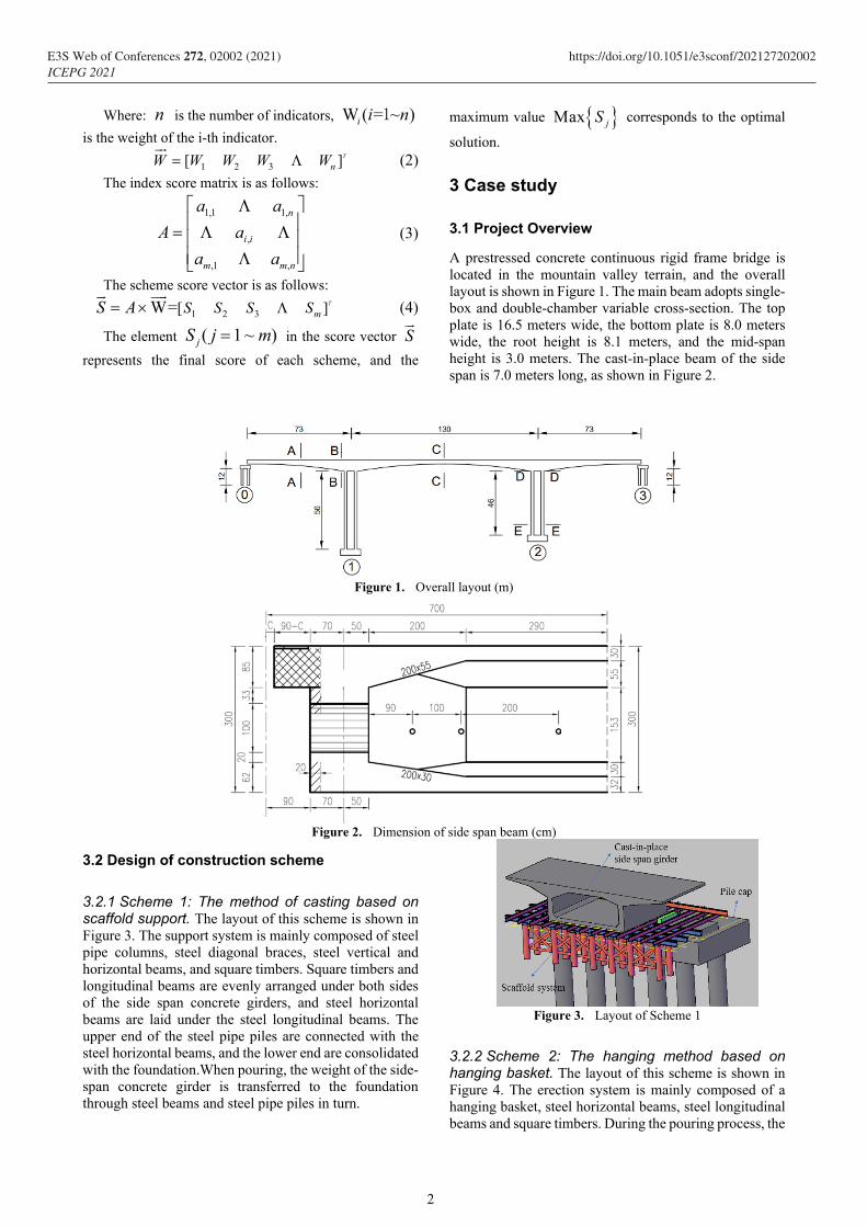
3.2.2 Scheme 2: The hanging method based on hanging basket. The layout of this scheme is shown in Figure 4. The erection system is mainly composed of a hanging basket, steel horizontal beams, steel longitudinal beams and square timbers. During the pouring process, the
2
E3S Web of Conferences 272, 02002 (2021) https://doi.org/10.1051/e3sconf/202127202002ICEPG 2021
weight of the concrete girders is transferred to the mid-span girders through the suspension rods of the hanging basket. The key control points of this scheme are the anchoring quality of the hanging basket system and the rigidity of the slings.
Figure 4. Layout of Scheme 2
3.2.3 Scheme 3: The method based on triangle bracket. The layout of this scheme is shown in Figure 5. The erection system is mainly composed of triangular brackets, vertical and horizontal beams, square timber and other components. The triangle bracket is consolidated with the abutment, and the weight of the concrete box girder is transmitted to the pier column through the triangle bracket.
Figure 5. Layout of Scheme 3
3.3 Performance analysis of construction scheme
3.3.1 Cost, duration and applicability. The scheme 1 is easy to operate and suitable for flat terrain. When facing steep terrain, it needs to spend money on foundation treatment, resulting in poor economy. The construction will take 50~60 days.
The construction technology of scheme 2 is relatively mature, which can be applied to the situation of insufficient site and steep terrain. It is necessary to configure the hanging basket system and the corresponding counterweight equipments. The construction of side span girders need 40 ~ 50 days.
The scheme 3 is suitable for the situation of insufficient site and foundation bearing conditions, and the construction technology is complex. The construction of side span girders need about 30 tons of steel, and the construction period is about 50 ~ 60 days.
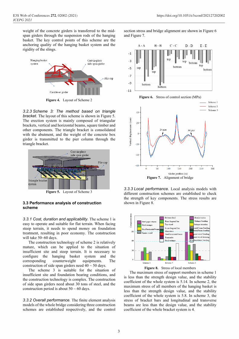
3.3.2 Overall performance. The finite element analysis models of the whole bridge considering three construction schemes are established respectively, and the control
section stress and bridge alignment are shown in Figure 6 and Figure 7.
Figure 6. Stress of control section (MPa)
Figure 7. Alignment of bridge
3.3.3 Local performance. Local analysis models with different construction schemes are established to check the strength of key components. The stress results are shown in Figure 8.
Figure 8. Stress of local members
The maximum stress of support members in scheme 1 is less than the strength design value, and the stability coefficient of the whole system is 5.14. In scheme 2, the maximum stress of all members of the hanging basket is less than the strength design value, and the stability coefficient of the whole system is 5.8. In scheme 3, the stress of bracket bars and longitudinal and transverse beams are less than the design value, and the stability coefficient of the whole bracket system is 4.
3
E3S Web of Conferences 272, 02002 (2021) https://doi.org/10.1051/e3sconf/202127202002ICEPG 2021
3.4 Comparison and selection of schemes
The first level evaluation indexes are: Overall performance C1, Construction period C2, Construction safety C3, Cost C4 and Applicability C5.
Establish a comparison matrix based on the relative importance of the indicators:
1 2 3 4 5
1
2,
3
4
5
1 2 2 2 2 9
0 1 0 0 2 3( )
0 2 1 2 2 7
0 2 0 1 2 5
0 0 0 0 1 1
i
i j
A c c c c c r
c
cA a
c
c
c
Where:
,
2 is more important than c
1 is as important as c
0 is more important than c
i j
i j i j
j i
c
a c
c
,
5
,1
i i jj
r a
Establish a matrix of consistent judgments based on extreme values:
1 2 3 4 5
1
2,
3
4
5
1 5.20 1.73 3 9 242.89 3 0.45
0.19 1 0.33 0.58 1.73 0.06 0.58 0.09C ( )
0.58 3 1 1.73 5.20 15.65 1.73 0.26
0.33 1.73 0.58 1 3 0.99 0.99 0.15
0.11 0.58 0.19 0.33 1 0.004 0.33 0.05
i i i
i j
C c c c c c M W W
c
cc
c
c
c
Where:
max min
55
, , 51 1
1
59 , , , , 6.64i jr r
r r ii j i i j i i i i
j ii
i
Wc M c W M W W
W
The maximum eigenvalue is calculated as follows:
5
1
1 2.26 0.44 1.31 0.76 0.25max = ( ) 5.004
5 0.45 0.99 0.26 0.15 0.05i
i i
d
nw
The consistency coefficient is calculated as follows:
. .
5.004 5= 0.001 ( 0.001)
4
max
1C IP
n
n
The result meets the inspection requirements, so the weight of each indicator is as follows:
T=(0.45 0.09 0.26 0.15 0.05)W
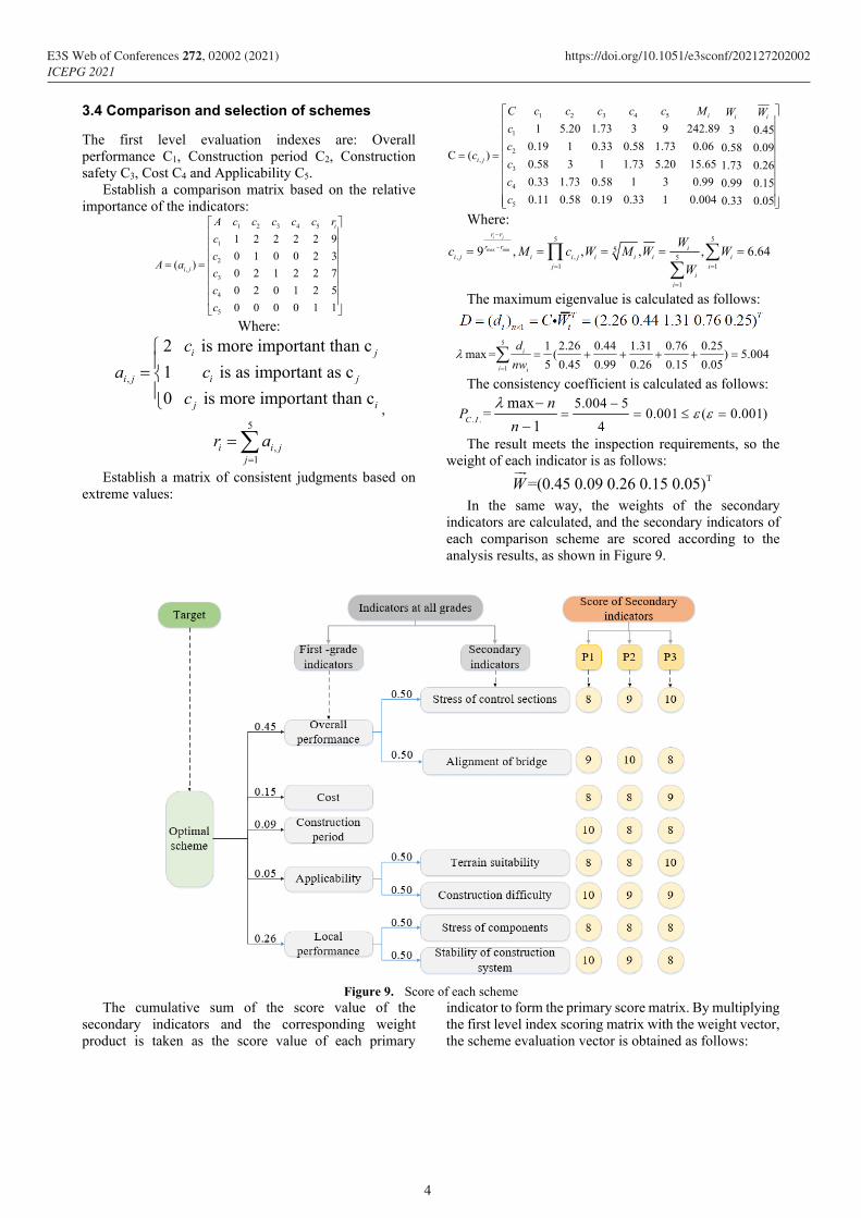
In the same way, the weights of the secondary
indicators are calculated, and the secondary indicators of each comparison scheme are scored according to the analysis results, as shown in Figure 9.
Figure 9. Score of each scheme
The cumulative sum of the score value of the secondary indicators and the corresponding weight product is taken as the score value of each primary
indicator to form the primary score matrix. By multiplying the first level index scoring matrix with the weight vector, the scheme evaluation vector is obtained as follows:
4
E3S Web of Conferences 272, 02002 (2021) https://doi.org/10.1051/e3sconf/202127202002ICEPG 2021
8.68 8.77 8.54
0.45
8.5 8 9 9 9 0.09
9.5 8 8 8.5 8.5 0.26
8.5 9 8 9.5 8 0.15
0.05
S A W
)(
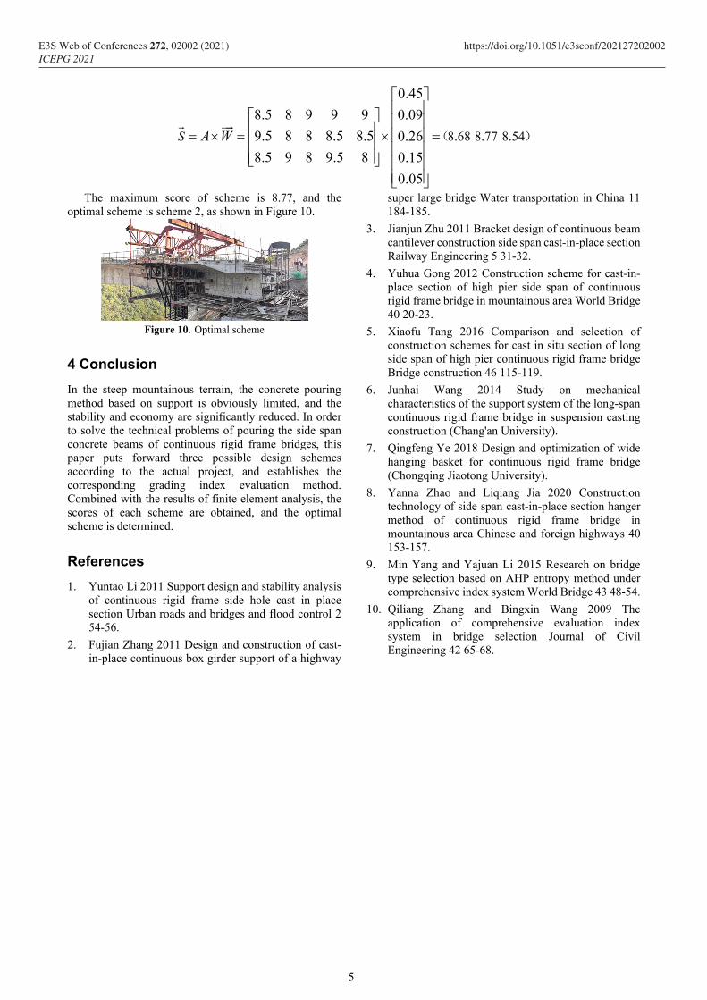
The maximum score of scheme is 8.77, and the optimal scheme is scheme 2, as shown in Figure 10.
Figure 10. Optimal scheme
4 Conclusion
In the steep mountainous terrain, the concrete pouring method based on support is obviously limited, and the stability and economy are significantly reduced. In order to solve the technical problems of pouring the side span concrete beams of continuous rigid frame bridges, this paper puts forward three possible design schemes according to the actual project, and establishes the corresponding grading index evaluation method. Combined with the results of finite element analysis, the scores of each scheme are obtained, and the optimal scheme is determined.
References
1. Yuntao Li 2011 Support design and stability analysis of continuous rigid frame side hole cast in place section Urban roads and bridges and flood control 2 54-56.
2. Fujian Zhang 2011 Design and construction of cast-in-place continuous box girder support of a highway
super large bridge Water transportation in China 11 184-185.
3. Jianjun Zhu 2011 Bracket design of continuous beam cantilever construction side span cast-in-place section Railway Engineering 5 31-32.
4. Yuhua Gong 2012 Construction scheme for cast-in-place section of high pier side span of continuous rigid frame bridge in mountainous area World Bridge 40 20-23.
5. Xiaofu Tang 2016 Comparison and selection of construction schemes for cast in situ section of long side span of high pier continuous rigid frame bridge Bridge construction 46 115-119.
6. Junhai Wang 2014 Study on mechanical characteristics of the support system of the long-span continuous rigid frame bridge in suspension casting construction (Chang'an University).
7. Qingfeng Ye 2018 Design and optimization of wide hanging basket for continuous rigid frame bridge (Chongqing Jiaotong University).
8. Yanna Zhao and Liqiang Jia 2020 Construction technology of side span cast-in-place section hanger method of continuous rigid frame bridge in mountainous area Chinese and foreign highways 40 153-157.
9. Min Yang and Yajuan Li 2015 Research on bridge type selection based on AHP entropy method under comprehensive index system World Bridge 43 48-54.
10. Qiliang Zhang and Bingxin Wang 2009 The application of comprehensive evaluation index system in bridge selection Journal of Civil Engineering 42 65-68.
5
E3S Web of Conferences 272, 02002 (2021) https://doi.org/10.1051/e3sconf/202127202002ICEPG 2021