Embed Size (px)
Citation preview
2013/05 – Subject to change 1
Compact Cylinders ADN/AEN/ADNGF – Inch Series, Based on ISO 21287
Compact cylinders for maximum productivity in confined spaces,
combining innovative technology, high performance and reduced
installation space requirements
• More than the standard: Piston∅½˝ to 5˝
• Variable strokes up to 20˝
• Compact cylinder with standard port pattern,
dimensions based on ISO 21287
• Innovative technology for maximum speeds
• Flexible in use thanks to customised variants
• Spare parts service
Product Range Overview
Function Type Piston∅ Stroke Force Variants
[in] [in] [lbf] A I P A Q S2 S20 K2 K8 S6 S1 R3
Basic version
Double-acting ADN ½,Æ,¾, 1, 1¼, 1Æ, 0.04 … 19.7 15 … 1,655� � � � � � � � � � � �
2, 2½, 3, 4, 5
Single-acting AEN ½,Æ,¾, 1, 1¼, 1Æ, 0.04 … 1 15 … 1,655� � � � � – – � � � – –
2, 2½, 3, 4
Non-rotating, with yoke
Double-acting ADNGF ½,Æ,¾, 1, 1¼, 1Æ, 0.04 … 15.75 15 … 1,060– – � � – � – – – – – –
2, 2½, 3, 4
Variants
A Male thread
I Female thread
P Flexible cushioning rings/pads at
both ends
A Position sensing
Q Square piston rod
S2 Through piston rod
S20 Through, hollow piston rod
K2 Extended male piston rod thread
K8 Extended piston rod
S6 Heat resistant seals up to
max. 248 °F
S1 Reinforced piston rod
R3 High corrosion protection
Features Contents
• Sensor slots on three sides for flush
mounting of proximity sensors
• Integrated cushioning rings for
absorbing residual energy at high
speeds and machine cycles
• Centering hole in the end cap
matches centering pins ZBS
More features� 2
Basic Version, Double-acting Basic Version, Single-acting Non-rotating, with Yoke, Double-acting
– Technical Data � 5 – Technical Data � 23 – Technical Data � 34
– Dimensional Drawings � 11 – Dimensional Drawings � 26 – Dimensional Drawings � 36
– Ordering Data � 16 – Ordering Data � 30 – Ordering Data � 38
– Accessories Overview � 32 – Accessories Overview � 32 – Accessories Overview � 41
– Accessories � 42 – Accessories � 42 – Accessories � 42
� www.festo.com/catalog/ADN � www.festo.com/catalog/AEN � www.festo.com/catalog/ADNGF
Subject to change – 2013/052
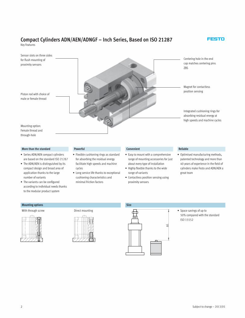
Compact Cylinders ADN/AEN/ADNGF – Inch Series, Based on ISO 21287Key Features
Piston rod with choice of
male or female thread
Mounting option:
Female thread and
through-hole
Sensor slots on three sides
for flush mounting of
proximity sensors
Magnet for contactless
position sensing
Integrated cushioning rings for
absorbing residual energy at
high speeds and machine cycles
Centering hole in the end
cap matches centering pins
ZBS
More than the standard Powerful Convenient Reliable
• Series ADN/AEN compact cylinders
are based on the standard ISO 21287
• The ADN/AEN is distinguished by its
compact design and broad area of
application thanks to the large
number of variants
• The variants can be configured
according to individual needs thanks
to the modular product system
• Flexible cushioning rings as standard
for absorbing the residual energy
facilitate high speeds and machine
cycles
• Long service life thanks to exceptional
cushioning characteristics and
minimal friction factors
• Easy to mount with a comprehensive
range of mounting accessories for just
about every type of installation
• Highly flexible thanks to the wide
range of variants
• Contactless position sensing using
proximity sensors
• Optimised manufacturing methods,
patented technology and more than
40 years of experience in the field of
cylinders make Festo and ADN/AEN a
great team
Mounting options Size
With through screw Direct mounting
ΔL
• Space savings of up to
50% compared with the standard
ISO 15552

2013/05 – Subject to change 3
Compact Cylinders ADN/AEN/ADNGF – Inch Series, Based on ISO 21287Key Features
Variants from the Modular System
Symbol Key features Description ADN AEN ADNGF
Q Square piston rod Protection against torsion. For correctly oriented feeding� � –
S2 Through piston rod For working at both ends with the same forces in the advance and return stroke,
for attaching external stops� – �
S20 Through, hollow piston
rod
For carrying vacuum, small parts, media, etc.� – –
K2 Extended male piston
rod thread
–� � –
K8 Extended piston rod –� � –
S6 Heat-resistant seals Temperature resistance up to max. 248 °F� � –
S1 Reinforced piston rod Increased lateral forces. Absorbs many times more lateral force than a basic
cylinder� – –
R3 High corrosion
protection
All external cylinder surfaces comply with corrosion resistance class 3 to Festo
standard 940 070. The piston rod is made from corrosion and acid resistant steel� – –
Software tools on CD-ROM:
Configuration of Festo product
modules
www.festo.com
Subject to change – 2013/054
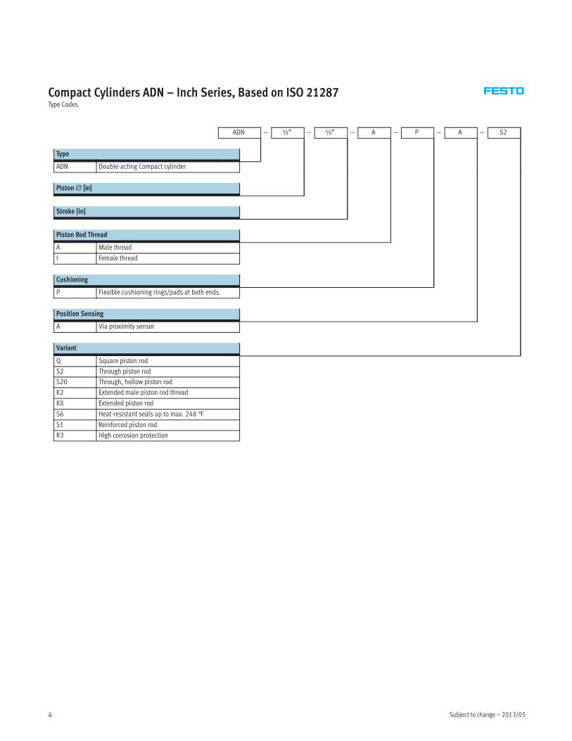
Compact Cylinders ADN – Inch Series, Based on ISO 21287Type Codes
ADN — ½” — ½” — A — P — A — S2
Type
ADN Double-acting Compact cylinder
Piston∅ [in]
Stroke [in]
Piston Rod Thread
A Male thread
I Female thread
Cushioning
P Flexible cushioning rings/pads at both ends
Position Sensing
A Via proximity sensor
Variant
Q Square piston rod
S2 Through piston rod
S20 Through, hollow piston rod
K2 Extended male piston rod thread
K8 Extended piston rod
S6 Heat-resistant seals up to max. 248 °F
S1 Reinforced piston rod
R3 High corrosion protection
2013/05 – Subject to change 5
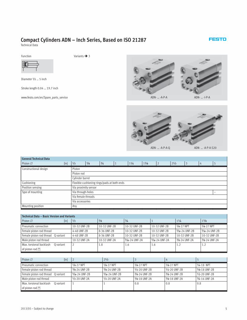
Compact Cylinders ADN – Inch Series, Based on ISO 21287Technical Data
Function
Diameter½ … 5 inch
Stroke length 0.04 … 19.7 inch
www.festo.com/en/Spare_parts_service
Variants� 3
ADN- … -A-P-A
ADN- … -A-P-A-S20
ADN- … -I-P-A
ADN- … -A-P-A-Q
General Technical Data
Piston∅ [in] ½ Æ ¾ 1 1¼ 1Æ 2 2½ 3 4 5
Constructional design Piston
Piston rod
Cylinder barrel
Cushioning Flexible cushioning rings/pads at both ends
Position sensing Via proximity sensor
Type of mounting Via through-holes –
Via female threads
Via accessories
Mounting position Any
Technical Data – Basic Version and Variants
Piston∅ [in] ½ Æ ¾ 1 1¼ 1Æ
Pneumatic connection 10-32 UNF-2B 10-32 UNF-2B 10-32 UNF-2B 10-32 UNF-2B x-27 NPT x-27 NPT
Female piston rod thread 4-48 UNF-2B 8-36 UNF-2B 10-32 UNF-2B 10-32 UNF-2B Ä-24 UNF-2B Ä-24 UNF-2B
Female piston rod thread Q variant 4-48 UNF-2B 8-36 UNF-2B 10-32 UNF-2B 10-32 UNF-2B 10-32 UNF-2B 10-32 UNF-2B
Male piston rod thread 10-32 UNF-2A 10-32 UNF-2A Ä-24 UNF-2A Ä-24 UNF-2A Å-24 UNF-2A Å-24 UNF-2A
Max. torsional backlash
of piston rod [°]
Q variant 2 1.8 1.6 1.6 1.2 1.2
Piston∅ [in] 2 2½ 3 4 5
Pneumatic connection x-27 NPT x-27 NPT x-27 NPT x-27 NPT ¼-18 NPT
Female piston rod thread Å-24 UNF-2B Å-24 UNF-2B ½-20 UNF-2B ½-20 UNF-2B Æ-18 UNF-2B
Female piston rod thread Q variant Ä-24 UNF-2B Ä-24 UNF-2B Å-24 UNF-2B Å-24 UNF-2B ½-20 UNF-2B
Male piston rod thread ½-20 UNF-2A ½-20 UNF-2A Æ-18 UNF-2A Æ-18 UNF-2A ¾-16 UNF-2A
Max. torsional backlash
of piston rod [°]
Q variant 1 1 0.8 0.8 0.8
Subject to change – 2013/056
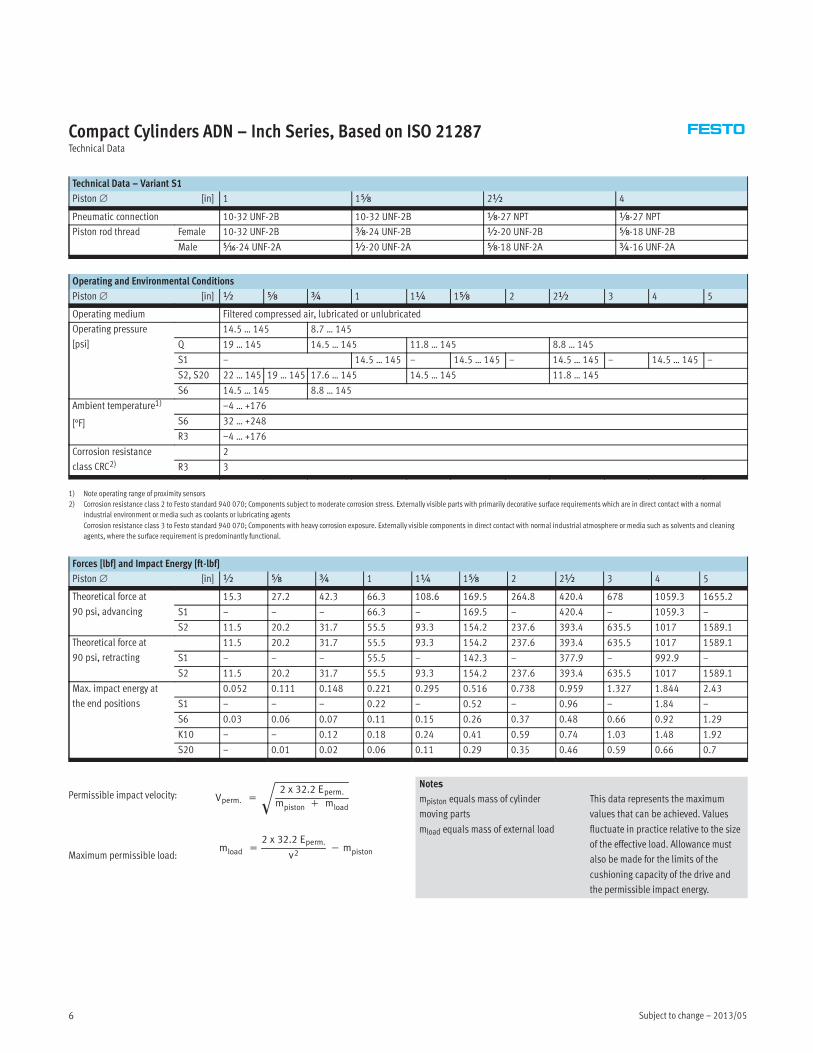
Compact Cylinders ADN – Inch Series, Based on ISO 21287Technical Data
Technical Data – Variant S1
Piston∅ [in] 1 1Æ 2½ 4
Pneumatic connection 10-32 UNF-2B 10-32 UNF-2B x-27 NPT x-27 NPT
Piston rod thread Female 10-32 UNF-2B Å-24 UNF-2B ½-20 UNF-2B Æ-18 UNF-2B
Male Ä-24 UNF-2A ½-20 UNF-2A Æ-18 UNF-2A ¾-16 UNF-2A
Operating and Environmental Conditions
Piston∅ [in] ½ Æ ¾ 1 1¼ 1Æ 2 2½ 3 4 5
Operating medium Filtered compressed air, lubricated or unlubricated
Operating pressure
[psi]
14.5 … 145 8.7 … 145
Q 19 … 145 14.5 … 145 11.8 … 145 8.8 … 145
S1 – 14.5 … 145 – 14.5 … 145 – 14.5 … 145 – 14.5 … 145 –
S2, S20 22 … 145 19 … 145 17.6 … 145 14.5 … 145 11.8 … 145
S6 14.5 … 145 8.8 … 145
Ambient temperature1)
[°F]
–4 … +176
S6 32 … +248
R3 –4 … +176
Corrosion resistance
class CRC2)2
R3 3
1) Note operating range of proximity sensors
2) Corrosion resistance class 2 to Festo standard 940 070; Components subject to moderate corrosion stress. Externally visible parts with primarily decorative surface requirements which are in direct contact with a normal
industrial environment or media such as coolants or lubricating agents
Corrosion resistance class 3 to Festo standard 940 070; Components with heavy corrosion exposure. Externally visible components in direct contact with normal industrial atmosphere or media such as solvents and cleaning
agents, where the surface requirement is predominantly functional.
Forces [lbf] and Impact Energy [ft-lbf]
Piston∅ [in] ½ Æ ¾ 1 1¼ 1Æ 2 2½ 3 4 5
Theoretical force at
90 psi, advancing
15.3 27.2 42.3 66.3 108.6 169.5 264.8 420.4 678 1059.3 1655.2
S1 – – – 66.3 – 169.5 – 420.4 – 1059.3 –
S2 11.5 20.2 31.7 55.5 93.3 154.2 237.6 393.4 635.5 1017 1589.1
Theoretical force at
90 psi, retracting
11.5 20.2 31.7 55.5 93.3 154.2 237.6 393.4 635.5 1017 1589.1
S1 – – – 55.5 – 142.3 – 377.9 – 992.9 –
S2 11.5 20.2 31.7 55.5 93.3 154.2 237.6 393.4 635.5 1017 1589.1
Max. impact energy at
the end positions
0.052 0.111 0.148 0.221 0.295 0.516 0.738 0.959 1.327 1.844 2.43
S1 – – – 0.22 – 0.52 – 0.96 – 1.84 –
S6 0.03 0.06 0.07 0.11 0.15 0.26 0.37 0.48 0.66 0.92 1.29
K10 – – 0.12 0.18 0.24 0.41 0.59 0.74 1.03 1.48 1.92
S20 – 0.01 0.02 0.06 0.11 0.29 0.35 0.46 0.59 0.66 0.7
Vperm. =
2 x 32.2 Eperm.
mpiston + mload�
mload =
2 x 32.2 Eperm.
v2− mpistonMaximum permissible load:
Permissible impact velocity:Notes
mpiston equals mass of cylinder
moving parts
mload equals mass of external load
This data represents the maximum
values that can be achieved. Values
fluctuate in practice relative to the size
of the effective load. Allowance must
also be made for the limits of the
cushioning capacity of the drive and
the permissible impact energy.
2013/05 – Subject to change 7
Compact Cylinders ADN – Inch Series, Based on ISO 21287Technical Data
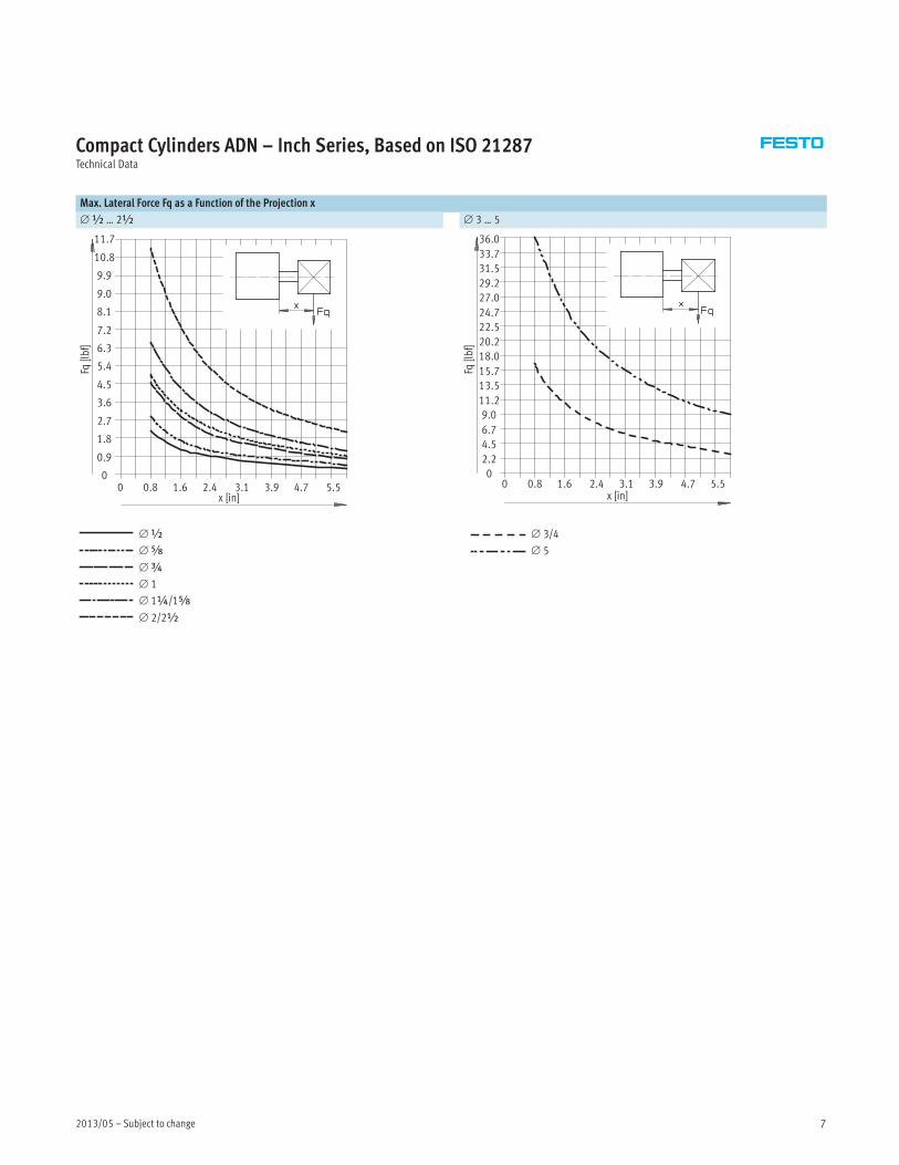
Max. Lateral Force Fq as a Function of the Projection x
∅½ … 2½ ∅ 3 … 5
x [in]
Fq[lbf]
11.7
10.8
9.9
9.0
8.1
7.2
6.3
5.4
4.5
3.6
2.7
1.8
0.9
00 0.8 1.6 2.4 3.1 3.9 4.7 5.5
x [in]
Fq[lbf]
0 0.8 1.6 2.4 3.1 3.9 4.7 5.5
36.0
33.7
31.5
29.2
27.0
24.7
22.5
20.2
18.0
15.7
13.5
11.2
9.0
6.7
4.5
2.2
0
∅½
∅Æ
∅¾
∅ 1
∅ 1¼/1Æ
∅ 2/2½
∅ 3/4
∅ 5
Subject to change – 2013/058
Compact Cylinders ADN – Inch Series, Based on ISO 21287Technical Data
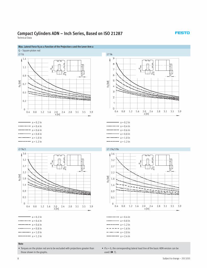
Max. Lateral Force Fq as a Function of the Projection x and the Lever Arm a
Q – Square piston rod
∅½ ∅Æ
x [in]
Fq[lbf]
1.4
1.1
0.9
0.7
0.5
0.2
00.4 0.8 1.2 1.6 2.0 2.4 2.8 3.1 3.5 3.9
x [in]
Fq[lbf]
0.4 0.8 1.2 1.6 2.0 2.4 2.8 3.1 3.5 3.9
a = 0.2 in
a = 0.4 in
a = 0.6 in
a = 0.8 in
a = 1.0 in
a = 1.2 in
a = 0.2 in
a = 0.4 in
a = 0.6 in
a = 0.8 in
a = 1.0 in
a = 1.2 in
∅¾/1 ∅ 1¼/1Æ
x [in]
Fq[lbf]
0.4 0.8 1.2 1.6 2.0 2.4 2.8 3.1 3.5 3.9
3.6
3.2
2.7
2.2
1.8
1.4
0.9
0.5
0
Fq[lbf]
x [in]0.4 0.8 1.2 1.6 2.0 2.4 2.8 3.1 3.5 3.9
3.6
3.2
2.7
2.2
1.8
1.4
0.9
0.5
0
a = 0.2 in
a = 0.4 in
a = 0.6 in
a = 0.8 in
a = 1.0 in
a = 1.2 in
a = 0.4 in
a = 0.8 in
a = 1.2 in
a = 1.6 in
a = 2.0 in
a = 2.4 in
Note
• Torques on the piston rod are to be excluded with projections greater than
those shown in the graphs.
• If a = 0, the corresponding lateral load line of the basic ADN version can be
used (� 7).
2013/05 – Subject to change 9
Compact Cylinders ADN – Inch Series, Based on ISO 21287Technical Data
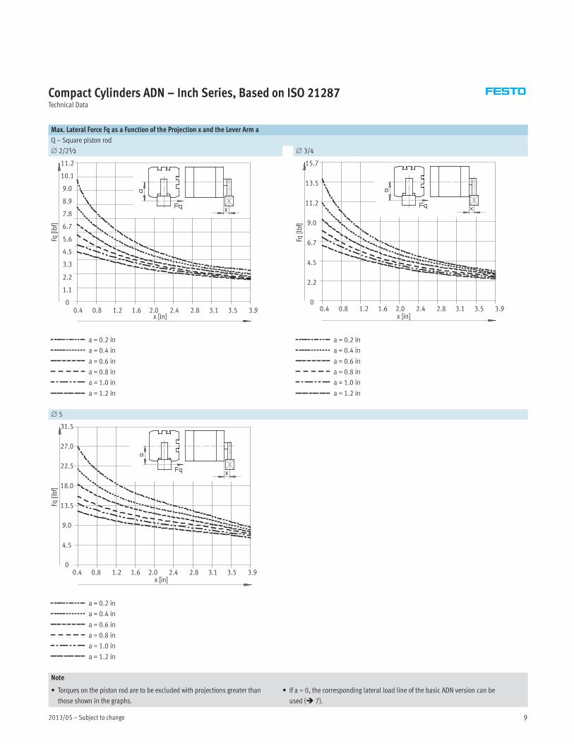
Max. Lateral Force Fq as a Function of the Projection x and the Lever Arm a
Q – Square piston rod
∅ 2/2½ ∅ 3/4
Fq[lbf]
x [in]
11.2
10.1
9.0
8.9
7.8
6.7
5.6
4.5
3.3
2.2
1.1
00.4 0.8 1.2 1.6 2.0 2.4 2.8 3.1 3.5 3.9
x [in]
Fq[lbf]
0.4 0.8 1.2 1.6 2.0 2.4 2.8 3.1 3.5 3.9
15.7
13.5
11.2
9.0
6.7
4.5
2.2
0
a = 0.2 in
a = 0.4 in
a = 0.6 in
a = 0.8 in
a = 1.0 in
a = 1.2 in
a = 0.2 in
a = 0.4 in
a = 0.6 in
a = 0.8 in
a = 1.0 in
a = 1.2 in
∅ 5
Fq[lbf]
x [in]0.4 0.8 1.2 1.6 2.0 2.4 2.8 3.1 3.5 3.9
31.5
27.0
22.5
18.0
13.5
9.0
4.5
0
a = 0.2 in
a = 0.4 in
a = 0.6 in
a = 0.8 in
a = 1.0 in
a = 1.2 in
Note
• Torques on the piston rod are to be excluded with projections greater than
those shown in the graphs.
• If a = 0, the corresponding lateral load line of the basic ADN version can be
used (� 7).

Subject to change – 2013/0510
Compact Cylinders ADN – Inch Series, Based on ISO 21287Technical Data
Max. Lateral Force Fq as a Function of the Projection x
S1 – Reinforced piston rod
x [in]
Fq[lbf]
0 8 16 24 32 40 48 56 64 72
225.0
112.0
45.0
22.5
11.2
4.5
2.2
1.1
0.4
0.2
∅ 1
∅ 1Æ
∅ 2½
∅ 4
Weight [lb]
Piston∅ ½ Æ ¾ 1 1¼ 1Æ 2 2½ 3 4 5
Product weight with 0 in stroke 0.15 0.16 0.26 0.31 0.53 0.69 1.08 1.44 2.6 4.31 5.76
Additional weight per 0.4 in stroke 0.02 0.03 0.04 0.05 0.06 0.07 0.1 0.12 0.16 0.2 0.23
Moving load with 0 in stroke 0.02 0.03 0.06 0.1 0.12 0.16 0.28 0.36 0.8 1.14 2.16
Additional load per 0.4 in stroke 0.01 0.01 0.01 0.01 0.02 0.02 0.03 0.03 0.05 0.05 0.08
Materials
Sectional view
1 2 3
4
1
Compact cylinder Basic version, Q S6 R3
1 Cover Anodised aluminum
2 Cylinder barrel Anodised aluminum
3 Piston rod High-alloy steel
4 Flange
screws
∅½ …Æ High-alloy steel High-alloy steel
∅¾ … 1 Galvanised steel High-alloy steel
∅ 1¼ … 2½ Galvanised steel Steel, zinc flake coating
∅ 3 … 5 Standard screws, galvanised steel Standard screws, high-alloy steel
– Seals Polyurethane Fluoro elastomer Polyurethane

2013/05 – Subject to change 11
Compact Cylinders ADN – Inch Series, Based on ISO 21287Dimensional Drawings
Dimensions – Basic Version1) Download CAD Data� www.festo.com/us/cad
∅½ … 2½
+ = plus stroke length
∅ 1¼ … 2½∅½ … 1∅½
∅ 3 … 5
+ = plus stroke length
∅
[in]
BG D1
∅
H9
D5
∅
F9
E EE G J2 J3 L2
max.
L3
+0.01
MM
∅
PL
+0.01
RT T2
+0.1
TG
±0.01
ZJ
+0.04
ß1
h13
[mm]
½0.67
0.35
0.241.08+0.01
10-32 UNF-2B
0.41 0.08 –1.38 0.14
0.24
0.24
M4
0.08
0.63 1.54 5
Æ 1.14+0.01 0.43
– 0.1
0.31 0.71 1.57 7
¾0.77
0.35
1.4+0.010.47
1.46
0.2
0.39 M50.87 1.68
91 1.56+0.01 1.54 1.02 1.76
1¼
1.06
1.85+0.01
x-27 NPT
0.59
– 0.24 1.730.47
0.32
M61.28 1.98
101Æ 2.15+0.01
– 0.31 1.771.5 2.02
2
0.47
0.472.58+0.01
0.63 M8
0.1
1.83 2.0913
2½ 2.97+0.01– 0.45
1.93 2.22 2.25
3 0.670.59
3.76+0.02 0.65 2.13 0.10.79 M10
2.83 2.4817
4 0.85 4.47+0.02 0.85 – 0.79 2.64 0.10.41
3.5 2.99
5 0.79 – 5.3+0.01 ¼-18 NPT 0.79 – 0.83 3.19 – 0.98 M12 4.33 3.62 21
1) Dimensions are in inches, unless otherwise noted.
Subject to change – 2013/0512
Compact Cylinders ADN – Inch Series, Based on ISO 21287Dimensional Drawings
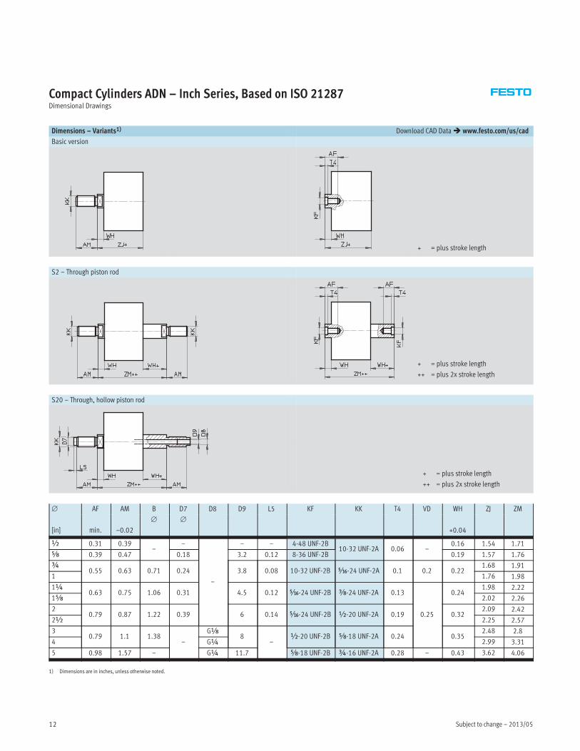
Dimensions – Variants1) Download CAD Data� www.festo.com/us/cad
Basic version
+ = plus stroke length
S2 – Through piston rod
+ = plus stroke length
++ = plus 2x stroke length
S20 – Through, hollow piston rod
+ = plus stroke length
++ = plus 2x stroke length
∅ AF AM B D7 D8 D9 L5 KF KK T4 VD WH ZJ ZM
[in] min. –0.02
∅ ∅
+0.04
½ 0.31 0.39–
–
–
– – 4-48 UNF-2B10-32 UNF-2A 0.06 –
0.16 1.54 1.71
Æ 0.39 0.47 0.18 3.2 0.12 8-36 UNF-2B 0.19 1.57 1.76
¾0.55 0.63 0.71 0.24 3.8 0.08 10-32 UNF-2B Ä-24 UNF-2A 0.1 0.2 0.22
1.68 1.91
1 1.76 1.98
1¼0.63 0.75 1.06 0.31 4.5 0.12 Ä-24 UNF-2B Å-24 UNF-2A 0.13
0.25
0.241.98 2.22
1Æ 2.02 2.26
20.79 0.87 1.22 0.39 6 0.14 Ä-24 UNF-2B ½-20 UNF-2A 0.19 0.32
2.09 2.42
2½ 2.25 2.57
30.79 1.1 1.38
–
Gx8
–½-20 UNF-2B Æ-18 UNF-2A 0.24 0.35
2.48 2.8
4 G¼ 2.99 3.31
5 0.98 1.57 – G¼ 11.7 Æ-18 UNF-2B ¾-16 UNF-2A 0.28 – 0.43 3.62 4.06
1) Dimensions are in inches, unless otherwise noted.
2013/05 – Subject to change 13
Compact Cylinders ADN – Inch Series, Based on ISO 21287Dimensional Drawings
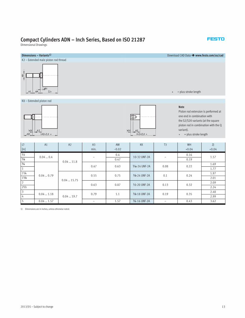
Dimensions – Variants1) Download CAD Data� www.festo.com/us/cad
K2 – Extended male piston rod thread
+ = plus stroke length
K8 – Extended piston rod
Note
Piston rod extension is performed at
one end in combination with
the S2/S20 variants (at the square
piston rod in combination with the Q
variant).
+ = plus stroke length
∅
[in]
A1 A2 A3
min.
AM
–0.02
KK T3 WH
+0.04
ZJ
+0.04
½0.04 … 0.4
0.04 … 11.8
–0.4
10-32 UNF-2A –0.16
1.57Æ 0.47 0.19
¾
0.04 … 0.79
0.47 0.63 Ä-24 UNF-2A 0.08 0.221.69
1 1.77
1¼
0.04 … 15.75
0.55 0.75 Å-24 UNF-2A 0.1 0.241.97
1Æ 2.01
20.63 0.87 ½-20 UNF-2A 0.13 0.32
2.09
2½ 2.24
30.04 … 1.18
0.04 … 19.70.79 1.1 Æ-18 UNF-2A 0.19 0.35
2.48
4 2.99
5 0.04 … 1.57 – 1.57 ¾-16 UNF-2A – 0.43 3.62
1) Dimensions are in inches, unless otherwise noted.

Subject to change – 2013/0514
Compact Cylinders ADN – Inch Series, Based on ISO 21287Dimensional Drawings
Dimensions – Variants1) Download CAD Data� www.festo.com/us/cad
Q – Square piston rod
+ = plus stroke length
Q-S2 – Square, through piston rod
+ = plus stroke length
++ = plus 2x stroke length
Q-S20 – Square, through, hollow piston rod
+ = plus stroke length
++ = plus 2x stroke length
∅
[in]
AF
min.
AM
–0.02
B1
�
D7
∅
D8 D9 KF KF3 KK L5 T4 WH
+0.04
ZJ ZM
½ 0.31 0.39 0.22 –
–
– 4-48 UNF-2B 4-48 UNF-2B10-32 UNF-2A 0.12 0.06
0.17 1.54 1.71
Æ 0.39 0.47 0.28 0.18 0.13 8-36 UNF-2B 8-36 UNF-2B 0.19 1.57 1.76
¾0.47 0.63 0.35 0.24 0.15 10-32 UNF-2B 10-32 UNF-2B Ä-24 UNF-2A 0.08 0.08 0.22
1.68 1.91
1 1.76 1.98
1¼0.55 0.75 0.39 0.31 0.18 Ä-24 UNF-2B 10-32 UNF-2B Å-24 UNF-2A 0.12 0.1 0.24
1.98 2.22
1Æ 2.02 2.26
20.63 0.87 0.47 0.39 0.24 Ä-24 UNF-2B Ä-24 UNF-2B ½-20 UNF-2A 0.14 0.13 0.32
2.09 2.42
2½ 2.25 2.57
30.79 1.1 0.63
–Gx
0.33½-20 UNF-2B Å-24 UNF-2B Æ-18 UNF-2A
–0.19 0.35
2.48 2.8
4 0.35 2.99 3.31
5 0.94 1.57 0.79 G¼ 0.45 Ä-24 UNF-2B ½-20 UNF-2B ¾-16 UNF-2A 0.24 0.43 3.62 4.06
1) Dimensions are in inches, unless otherwise noted.
2013/05 – Subject to change 15
Compact Cylinders ADN – Inch Series, Based on ISO 21287Dimensional Drawings
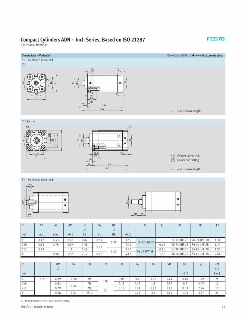
Dimensions – Variants1) Download CAD Data� www.festo.com/us/cad
S1 – Reinforced piston rod
∅ 1
+ = plus stroke length
∅ 1Æ … 4
1 Cylinder advancing
2 Cylinder retracting
+ = plus stroke length
S1 – Reinforced piston rod
∅
[in]
A3
min.
AF
min.
AM
–0.5
B
∅
F8
BG
min.
D1
∅
H9
E
+0.01
EE J3 KF KK L2
1 0.47 0.55 0.63 0.87 0.590.35
1.5610-32 UNF-2B
– 10-32 UNF-2B Ä-24 UNF-2B 1.54
1Æ 0.63 0.79 0.87 1.380.63
2.15 0.59 Å-24 UNF-2B ½-20 UNF-2B 1.77
2½ 0.79 1.1 1.650.47
2.97x-27 NPT-2B
0.91 ½-20 UNF-2B Æ-18 UNF-2B 1.93
4 – 0.98 1.57 2.17 0.67 4.47 1.57 Æ-18 UNF-2B ¾-16 UNF-2B 2.64
∅
[in]
L3 MM
∅
PM RT T2 T3 T4 TG VD WH
+1.3
ZJ ß1
h13
[mm]
1 0.2 0.39 0.24 M50.08
0.08 0.1 1.02 0.24 0.46 1.99 9
1Æ 0.630.32
M6 0.13 0.19 1.5 0.37 0.7 2.47 13
2½ 0.79 M80.1
0.19 0.24 2.22 0.47 0.83 2.76 17
4 0.98 0.41 M10 – 0.28 3.5 0.61 1.04 3.67 21
1) Dimensions are in inches, unless otherwise noted.
Subject to change – 2013/0516
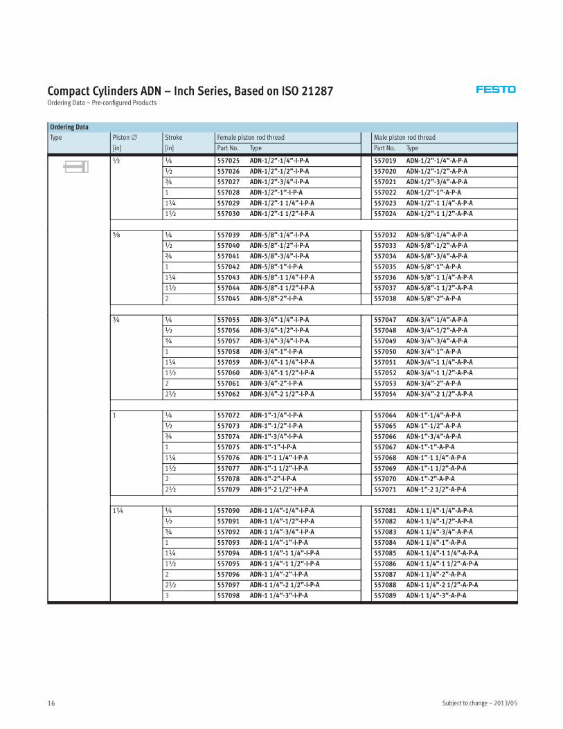
Compact Cylinders ADN – Inch Series, Based on ISO 21287Ordering Data – Pre-configured Products
Ordering Data
Type Piston∅ Stroke Female piston rod thread Male piston rod thread
[in] [in] Part No. Type Part No. Type
½ ¼ 557025 ADN-1/2”-1/4”-I-P-A 557019 ADN-1/2”-1/4”-A-P-A
½ 557026 ADN-1/2”-1/2”-I-P-A 557020 ADN-1/2”-1/2”-A-P-A
¾ 557027 ADN-1/2”-3/4”-I-P-A 557021 ADN-1/2”-3/4”-A-P-A
1 557028 ADN-1/2”-1”-I-P-A 557022 ADN-1/2”-1”-A-P-A
1¼ 557029 ADN-1/2”-1 1/4”-I-P-A 557023 ADN-1/2”-1 1/4”-A-P-A
1½ 557030 ADN-1/2”-1 1/2”-I-P-A 557024 ADN-1/2”-1 1/2”-A-P-A
Æ ¼ 557039 ADN-5/8”-1/4”-I-P-A 557032 ADN-5/8”-1/4”-A-P-A
½ 557040 ADN-5/8”-1/2”-I-P-A 557033 ADN-5/8”-1/2”-A-P-A
¾ 557041 ADN-5/8”-3/4”-I-P-A 557034 ADN-5/8”-3/4”-A-P-A
1 557042 ADN-5/8”-1”-I-P-A 557035 ADN-5/8”-1”-A-P-A
1¼ 557043 ADN-5/8”-1 1/4”-I-P-A 557036 ADN-5/8”-1 1/4”-A-P-A
1½ 557044 ADN-5/8”-1 1/2”-I-P-A 557037 ADN-5/8”-1 1/2”-A-P-A
2 557045 ADN-5/8”-2”-I-P-A 557038 ADN-5/8”-2”-A-P-A
¾ ¼ 557055 ADN-3/4”-1/4”-I-P-A 557047 ADN-3/4”-1/4”-A-P-A
½ 557056 ADN-3/4”-1/2”-I-P-A 557048 ADN-3/4”-1/2”-A-P-A
¾ 557057 ADN-3/4”-3/4”-I-P-A 557049 ADN-3/4”-3/4”-A-P-A
1 557058 ADN-3/4”-1”-I-P-A 557050 ADN-3/4”-1”-A-P-A
1¼ 557059 ADN-3/4”-1 1/4”-I-P-A 557051 ADN-3/4”-1 1/4”-A-P-A
1½ 557060 ADN-3/4”-1 1/2”-I-P-A 557052 ADN-3/4”-1 1/2”-A-P-A
2 557061 ADN-3/4”-2”-I-P-A 557053 ADN-3/4”-2”-A-P-A
2½ 557062 ADN-3/4”-2 1/2”-I-P-A 557054 ADN-3/4”-2 1/2”-A-P-A
1 ¼ 557072 ADN-1”-1/4”-I-P-A 557064 ADN-1”-1/4”-A-P-A
½ 557073 ADN-1”-1/2”-I-P-A 557065 ADN-1”-1/2”-A-P-A
¾ 557074 ADN-1”-3/4”-I-P-A 557066 ADN-1”-3/4”-A-P-A
1 557075 ADN-1”-1”-I-P-A 557067 ADN-1”-1”-A-P-A
1¼ 557076 ADN-1”-1 1/4”-I-P-A 557068 ADN-1”-1 1/4”-A-P-A
1½ 557077 ADN-1”-1 1/2”-I-P-A 557069 ADN-1”-1 1/2”-A-P-A
2 557078 ADN-1”-2”-I-P-A 557070 ADN-1”-2”-A-P-A
2½ 557079 ADN-1”-2 1/2”-I-P-A 557071 ADN-1”-2 1/2”-A-P-A
1¼ ¼ 557090 ADN-1 1/4”-1/4”-I-P-A 557081 ADN-1 1/4”-1/4”-A-P-A
½ 557091 ADN-1 1/4”-1/2”-I-P-A 557082 ADN-1 1/4”-1/2”-A-P-A
¾ 557092 ADN-1 1/4”-3/4”-I-P-A 557083 ADN-1 1/4”-3/4”-A-P-A
1 557093 ADN-1 1/4”-1”-I-P-A 557084 ADN-1 1/4”-1”-A-P-A
1¼ 557094 ADN-1 1/4”-1 1/4”-I-P-A 557085 ADN-1 1/4”-1 1/4”-A-P-A
1½ 557095 ADN-1 1/4”-1 1/2”-I-P-A 557086 ADN-1 1/4”-1 1/2”-A-P-A
2 557096 ADN-1 1/4”-2”-I-P-A 557087 ADN-1 1/4”-2”-A-P-A
2½ 557097 ADN-1 1/4”-2 1/2”-I-P-A 557088 ADN-1 1/4”-2 1/2”-A-P-A
3 557098 ADN-1 1/4”-3”-I-P-A 557089 ADN-1 1/4”-3”-A-P-A
2013/05 – Subject to change 17
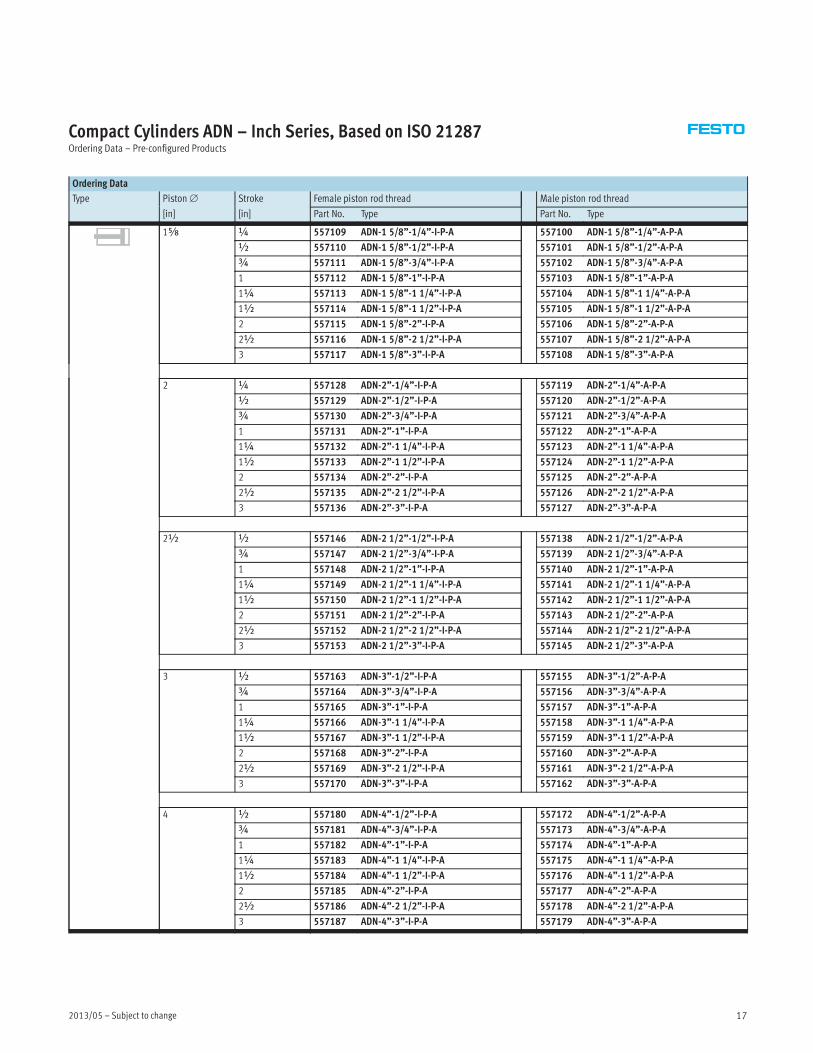
Compact Cylinders ADN – Inch Series, Based on ISO 21287Ordering Data – Pre-configured Products
Ordering Data
Type Piston∅ Stroke Female piston rod thread Male piston rod thread
[in] [in] Part No. Type Part No. Type
1Æ ¼ 557109 ADN-1 5/8”-1/4”-I-P-A 557100 ADN-1 5/8”-1/4”-A-P-A
½ 557110 ADN-1 5/8”-1/2”-I-P-A 557101 ADN-1 5/8”-1/2”-A-P-A
¾ 557111 ADN-1 5/8”-3/4”-I-P-A 557102 ADN-1 5/8”-3/4”-A-P-A
1 557112 ADN-1 5/8”-1”-I-P-A 557103 ADN-1 5/8”-1”-A-P-A
1¼ 557113 ADN-1 5/8”-1 1/4”-I-P-A 557104 ADN-1 5/8”-1 1/4”-A-P-A
1½ 557114 ADN-1 5/8”-1 1/2”-I-P-A 557105 ADN-1 5/8”-1 1/2”-A-P-A
2 557115 ADN-1 5/8”-2”-I-P-A 557106 ADN-1 5/8”-2”-A-P-A
2½ 557116 ADN-1 5/8”-2 1/2”-I-P-A 557107 ADN-1 5/8”-2 1/2”-A-P-A
3 557117 ADN-1 5/8”-3”-I-P-A 557108 ADN-1 5/8”-3”-A-P-A
2 ¼ 557128 ADN-2”-1/4”-I-P-A 557119 ADN-2”-1/4”-A-P-A
½ 557129 ADN-2”-1/2”-I-P-A 557120 ADN-2”-1/2”-A-P-A
¾ 557130 ADN-2”-3/4”-I-P-A 557121 ADN-2”-3/4”-A-P-A
1 557131 ADN-2”-1”-I-P-A 557122 ADN-2”-1”-A-P-A
1¼ 557132 ADN-2”-1 1/4”-I-P-A 557123 ADN-2”-1 1/4”-A-P-A
1½ 557133 ADN-2”-1 1/2”-I-P-A 557124 ADN-2”-1 1/2”-A-P-A
2 557134 ADN-2”-2”-I-P-A 557125 ADN-2”-2”-A-P-A
2½ 557135 ADN-2”-2 1/2”-I-P-A 557126 ADN-2”-2 1/2”-A-P-A
3 557136 ADN-2”-3”-I-P-A 557127 ADN-2”-3”-A-P-A
2½ ½ 557146 ADN-2 1/2”-1/2”-I-P-A 557138 ADN-2 1/2”-1/2”-A-P-A
¾ 557147 ADN-2 1/2”-3/4”-I-P-A 557139 ADN-2 1/2”-3/4”-A-P-A
1 557148 ADN-2 1/2”-1”-I-P-A 557140 ADN-2 1/2”-1”-A-P-A
1¼ 557149 ADN-2 1/2”-1 1/4”-I-P-A 557141 ADN-2 1/2”-1 1/4”-A-P-A
1½ 557150 ADN-2 1/2”-1 1/2”-I-P-A 557142 ADN-2 1/2”-1 1/2”-A-P-A
2 557151 ADN-2 1/2”-2”-I-P-A 557143 ADN-2 1/2”-2”-A-P-A
2½ 557152 ADN-2 1/2”-2 1/2”-I-P-A 557144 ADN-2 1/2”-2 1/2”-A-P-A
3 557153 ADN-2 1/2”-3”-I-P-A 557145 ADN-2 1/2”-3”-A-P-A
3 ½ 557163 ADN-3”-1/2”-I-P-A 557155 ADN-3”-1/2”-A-P-A
¾ 557164 ADN-3”-3/4”-I-P-A 557156 ADN-3”-3/4”-A-P-A
1 557165 ADN-3”-1”-I-P-A 557157 ADN-3”-1”-A-P-A
1¼ 557166 ADN-3”-1 1/4”-I-P-A 557158 ADN-3”-1 1/4”-A-P-A
1½ 557167 ADN-3”-1 1/2”-I-P-A 557159 ADN-3”-1 1/2”-A-P-A
2 557168 ADN-3”-2”-I-P-A 557160 ADN-3”-2”-A-P-A
2½ 557169 ADN-3”-2 1/2”-I-P-A 557161 ADN-3”-2 1/2”-A-P-A
3 557170 ADN-3”-3”-I-P-A 557162 ADN-3”-3”-A-P-A
4 ½ 557180 ADN-4”-1/2”-I-P-A 557172 ADN-4”-1/2”-A-P-A
¾ 557181 ADN-4”-3/4”-I-P-A 557173 ADN-4”-3/4”-A-P-A
1 557182 ADN-4”-1”-I-P-A 557174 ADN-4”-1”-A-P-A
1¼ 557183 ADN-4”-1 1/4”-I-P-A 557175 ADN-4”-1 1/4”-A-P-A
1½ 557184 ADN-4”-1 1/2”-I-P-A 557176 ADN-4”-1 1/2”-A-P-A
2 557185 ADN-4”-2”-I-P-A 557177 ADN-4”-2”-A-P-A
2½ 557186 ADN-4”-2 1/2”-I-P-A 557178 ADN-4”-2 1/2”-A-P-A
3 557187 ADN-4”-3”-I-P-A 557179 ADN-4”-3”-A-P-A
Subject to change – 2013/0518
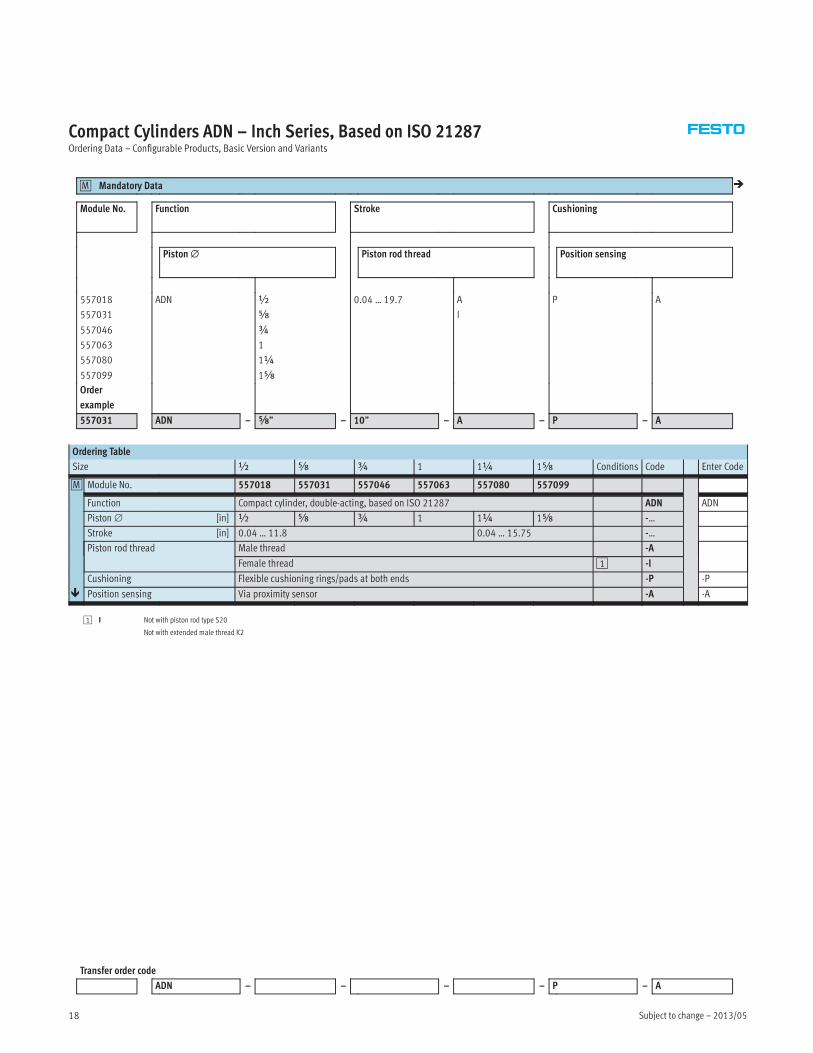
Compact Cylinders ADN – Inch Series, Based on ISO 21287Ordering Data – Configurable Products, Basic Version and Variants
Mandatory Data0M �
Module No. Function Stroke Cushioning
Piston∅ Piston rod thread Position sensing
557018
557031
557046
557063
557080
557099
ADN ½
Æ
¾
1
1¼
1Æ
0.04 … 19.7 A
I
P A
Order
example
557031 ADN – Æ” – 10” – A – P – A
Ordering Table
Size ½ Æ ¾ 1 1¼ 1Æ Conditions Code Enter Code
0M Module No. 557018 557031 557046 557063 557080 557099
Function Compact cylinder, double-acting, based on ISO 21287 ADN ADN
Piston∅ [in] ½ Æ ¾ 1 1¼ 1Æ -…
Stroke [in] 0.04 … 11.8 0.04 … 15.75 -…
Piston rod thread Male thread -A
Female thread 1 -I
Cushioning Flexible cushioning rings/pads at both ends -P -P
� Position sensing Via proximity sensor -A -A
1 I Not with piston rod type S20
Not with extended male thread K2
Transfer order code
ADN – – – – P – A
2013/05 – Subject to change 19
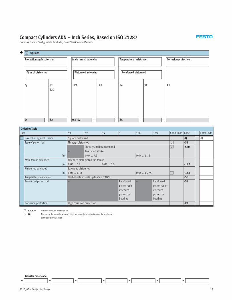
Compact Cylinders ADN – Inch Series, Based on ISO 21287Ordering Data – Configurable Products, Basic Version and Variants
� Options0O
Protection against torsion Male thread extended Temperature resistance Corrosion protection
Type of piston rod Piston rod extended Reinforced piston rod
Q S2
S20
…K2 …K8 S6 S1 R3
– Q – S2 – 0.2”K2 – – S6 – –
Ordering Table
Size ½ Æ ¾ 1 1¼ 1Æ Conditions Code Enter Code
0O Protection against torsion Square piston rod -Q -Q
Type of piston rod Through piston rod 2 -S2
–
Through, hollow piston rod 2 -S20
Restricted stroke
[in] 0.04 … 7.9 0.04 … 11.8
Male thread extended Extended male piston rod thread
[in] 0.04 … 0.4 0.04 … 0.8 -…K2
Piston rod extended Extended piston rod
[in] 0.04 … 11.8 0.04 … 15.75 3 -…K8
Temperature resistance Heat-resistant seals up to max. 248 °F -S6
Reinforced piston rod – Reinforced
piston rod or
extended
piston rod
bearing
– Reinforced
piston rod or
extended
piston rod
bearing
-S1
Corrosion protection High corrosion protection -R3
2 S2, S20 Not with corrosion protection R3
3 K8 The sum of the stroke length and piston rod extension must not exceed the maximum
permissible stroke length
Transfer order code
– – – – – – –

Subject to change – 2013/0520
Compact Cylinders ADN – Inch Series, Based on ISO 21287Ordering Data – Configurable Products, Basic Version and Variants
Mandatory Data0M �
Module No. Function Stroke Cushioning
Piston∅ Piston rod thread Position sensing
557118
557137
557154
557171
557395
ADN 2
2½
3
4
5
0.04 … 19.7 A
I
P A
Order
example
557118 ADN – 2” – 10” – A – P – A
Ordering Table
Size 2 2½ 3 4 5 Conditions Code Enter Code
0M Module No. 557118 557137 557154 557171 557395
Function Compact cylinder, double-acting, based on ISO 21287 ADN ADN
Piston∅ [in] 2 2½ 3 4 5 -…
Stroke [in] 0.04 … 15.75 0.04 … 19.7 -…
Piston rod thread Male thread -A
Female thread 1 -I
Cushioning Flexible cushioning rings/pads at both ends -P -P
� Position sensing Via proximity sensor -A -A
1 I Not with piston rod type S20
Not with extended male thread K2
Transfer order code
ADN – – – – P – A
2013/05 – Subject to change 21
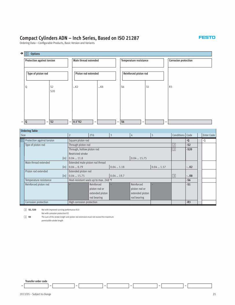
Compact Cylinders ADN – Inch Series, Based on ISO 21287Ordering Data – Configurable Products, Basic Version and Variants
� Options0O
Protection against torsion Male thread extended Temperature resistance Corrosion protection
Type of piston rod Piston rod extended Reinforced piston rod
Q S2
S20
…K2 …K8 S6 S1 R3
– Q – S2 – 0.5”K2 – – S6 – –
Ordering Table
Size 2 2½ 3 4 5 Conditions Code Enter Code
0O Protection against torsion Square piston rod -Q -Q
Type of piston rod Through piston rod 2 -S2
Through, hollow piston rod 2 -S20
Restricted stroke
[in] 0.04 … 11.8 0.04 … 15.75
Male thread extended Extended male piston rod thread
[in] 0.04 … 0.79 0.04 … 1.18 0.04 … 1.57 -…K2
Piston rod extended Extended piston rod
[in] 0.04 … 15.75 0.04 … 19.7 3 -…K8
Temperature resistance Heat-resistant seals up to max. 248 °F -S6
Reinforced piston rod – Reinforced
piston rod or
extended piston
rod bearing
– Reinforced
piston rod or
extended piston
rod bearing
– -S1
Corrosion protection High corrosion protection -R3
2 S2, S20 Not with improved running performance K10
Not with corrosion protection R3
3 K8 The sum of the stroke length and piston rod extension must not exceed the maximum
permissible stroke length
Transfer order code
– – – – – – –
Subject to change – 2013/0522
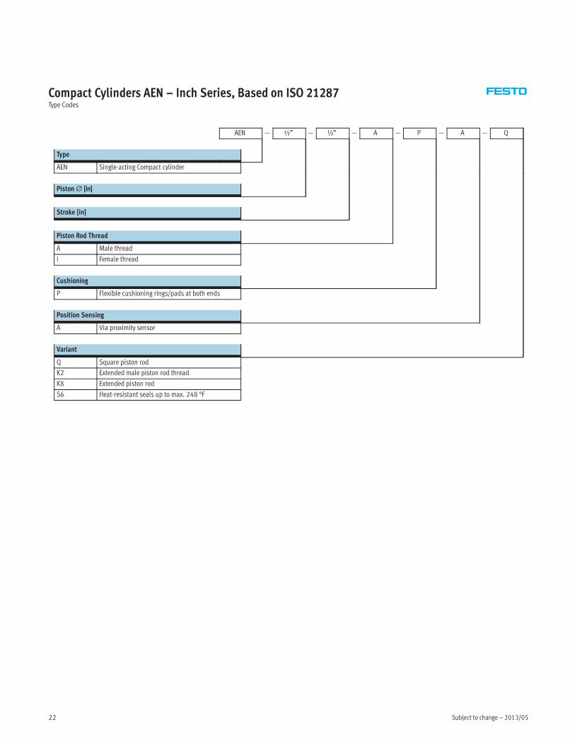
Compact Cylinders AEN – Inch Series, Based on ISO 21287Type Codes
AEN — ½” — ½” — A — P — A — Q
Type
AEN Single-acting Compact cylinder
Piston∅ [in]
Stroke [in]
Piston Rod Thread
A Male thread
I Female thread
Cushioning
P Flexible cushioning rings/pads at both ends
Position Sensing
A Via proximity sensor
Variant
Q Square piston rod
K2 Extended male piston rod thread
K8 Extended piston rod
S6 Heat-resistant seals up to max. 248 °F
2013/05 – Subject to change 23
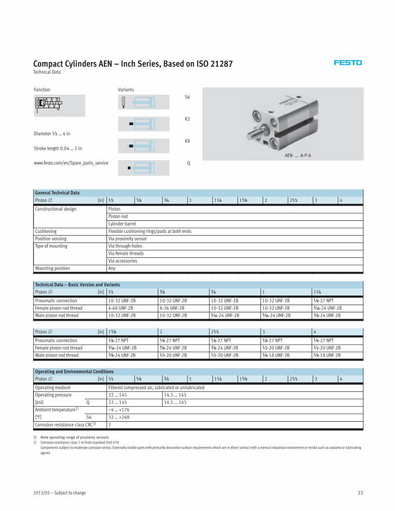
Compact Cylinders AEN – Inch Series, Based on ISO 21287Technical Data
Function
Diameter½ … 4 in
Stroke length 0.04 … 1 in
www.festo.com/en/Spare_parts_service
Variants
S6
K2
K8
Q
AEN- … -A-P-A
General Technical Data
Piston∅ [in] ½ Æ ¾ 1 1¼ 1Æ 2 2½ 3 4
Constructional design Piston
Piston rod
Cylinder barrel
Cushioning Flexible cushioning rings/pads at both ends
Position sensing Via proximity sensor
Type of mounting Via through-holes
Via female threads
Via accessories
Mounting position Any
Technical Data – Basic Version and Variants
Piston∅ [in] ½ Æ ¾ 1 1¼
Pneumatic connection 10-32 UNF-2B 10-32 UNF-2B 10-32 UNF-2B 10-32 UNF-2B x-27 NPT
Female piston rod thread 4-48 UNF-2B 8-36 UNF-2B 10-32 UNF-2B 10-32 UNF-2B Ä-24 UNF-2B
Male piston rod thread 10-32 UNF-2B 10-32 UNF-2B Ä-24 UNF-2B Ä-24 UNF-2B Å-24 UNF-2B
Piston∅ [in] 1Æ 2 2½ 3 4
Pneumatic connection x-27 NPT x-27 NPT x-27 NPT x-27 NPT x-27 NPT
Female piston rod thread Ä-24 UNF-2B Å-24 UNF-2B Å-24 UNF-2B ½-20 UNF-2B ½-20 UNF-2B
Male piston rod thread Å-24 UNF-2B ½-20 UNF-2B ½-20 UNF-2B Æ-18 UNF-2B Æ-18 UNF-2B
Operating and Environmental Conditions
Piston∅ [in] ½ Æ ¾ 1 1¼ 1Æ 2 2½ 3 4
Operating medium Filtered compressed air, lubricated or unlubricated
Operating pressure
[psi]
22 … 145 14.5 … 145
Q 22 … 145 14.5 … 145
Ambient temperature1)
[°F]
–4 … +176
S6 32 … +248
Corrosion resistance class CRC2) 2
1) Note operating range of proximity sensors
2) Corrosion resistance class 2 to Festo standard 940 070
Components subject to moderate corrosion stress. Externally visible parts with primarily decorative surface requirements which are in direct contact with a normal industrial environment or media such as coolants or lubricating
agents
Subject to change – 2013/0524
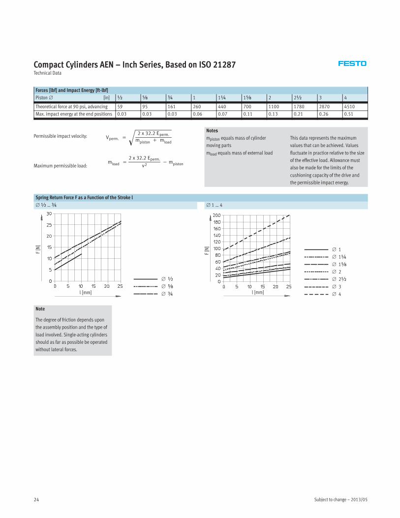
Compact Cylinders AEN – Inch Series, Based on ISO 21287Technical Data
Forces [lbf] and Impact Energy [ft-lbf]
Piston∅ [in] ½ Æ ¾ 1 1¼ 1Æ 2 2½ 3 4
Theoretical force at 90 psi, advancing 59 95 161 260 440 700 1100 1780 2870 4510
Max. impact energy at the end positions 0.03 0.03 0.03 0.06 0.07 0.11 0.13 0.21 0.26 0.51
Vperm. =
2 x 32.2 Eperm.
mpiston + mload�
mload =
2 x 32.2 Eperm.
v2− mpistonMaximum permissible load:
Permissible impact velocity:Notes
mpiston equals mass of cylinder
moving parts
mload equals mass of external load
This data represents the maximum
values that can be achieved. Values
fluctuate in practice relative to the size
of the effective load. Allowance must
also be made for the limits of the
cushioning capacity of the drive and
the permissible impact energy.
Spring Return Force F as a Function of the Stroke l
∅½ …¾ ∅ 1 … 4
F[N]
l [mm]
∅ ½
∅ Æ
∅ ¾ l [mm]
F[N]
∅ 1
∅ 1¼
∅ 1Æ
∅ 2
∅ 2½
∅ 3
∅ 4
Note
The degree of friction depends upon
the assembly position and the type of
load involved. Single-acting cylinders
should as far as possible be operated
without lateral forces.
2013/05 – Subject to change 25
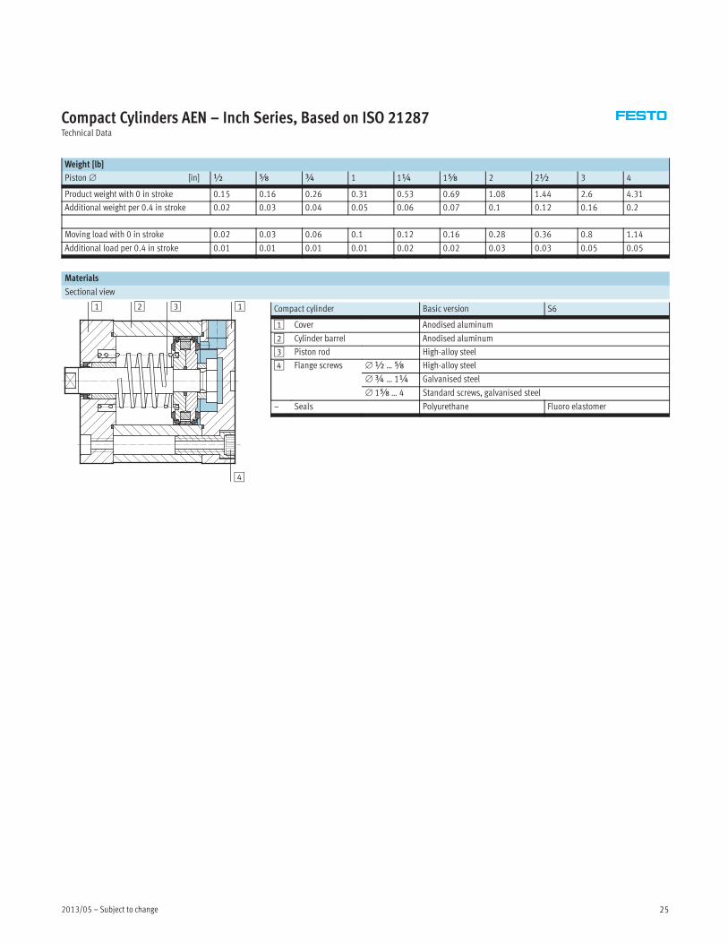
Compact Cylinders AEN – Inch Series, Based on ISO 21287Technical Data
Weight [lb]
Piston∅ [in] ½ Æ ¾ 1 1¼ 1Æ 2 2½ 3 4
Product weight with 0 in stroke 0.15 0.16 0.26 0.31 0.53 0.69 1.08 1.44 2.6 4.31
Additional weight per 0.4 in stroke 0.02 0.03 0.04 0.05 0.06 0.07 0.1 0.12 0.16 0.2
Moving load with 0 in stroke 0.02 0.03 0.06 0.1 0.12 0.16 0.28 0.36 0.8 1.14
Additional load per 0.4 in stroke 0.01 0.01 0.01 0.01 0.02 0.02 0.03 0.03 0.05 0.05
Materials
Sectional view
Compact cylinder Basic version S6
1 Cover Anodised aluminum
2 Cylinder barrel Anodised aluminum
3 Piston rod High-alloy steel
4 Flange screws ∅½ …Æ High-alloy steel
∅¾ … 1¼ Galvanised steel
∅ 1Æ … 4 Standard screws, galvanised steel
– Seals Polyurethane Fluoro elastomer
21 3
4
1
Subject to change – 2013/0526
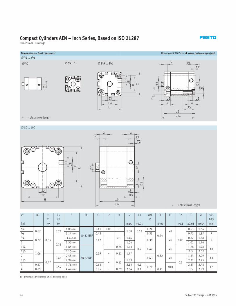
Compact Cylinders AEN – Inch Series, Based on ISO 21287Dimensional Drawings
Dimensions – Basic Version1) Download CAD Data� www.festo.com/us/cad
∅½ … 2½
+ = plus stroke length
∅ 1¼ … 2½∅½ … 1∅½
∅ 80 … 100
+ = plus stroke length
∅
[in]
BG D1
∅
H9
D5
∅
F9
E EE G J2 J3 L2
max.
L3
+0.01
MM
∅
PL
+0.01
RT T2
+0.1
TG
±0.01
ZJ
+0.04
ß1
h13
[mm]
½0.67
0.35
0.241.08+0.01
10-32 UNF
0.41 0.08 –1.38 0.14
0.24
0.24
M4
0.08
0.63 1.54 5
Æ 1.14+0.01 0.43
– 0.1
0.31 0.71 1.57 7
¾0.77
0.35
1.4+0.010.47
1.46
0.2
0.39 M50.87 1.68
91 1.56+0.01 1.54 1.02 1.76
1¼
1.06
1.85+0.01
x-27 NPT
0.59
– 0.24 1.730.47
0.32
M61.28 1.98
101Æ 2.15+0.01
– 0.31 1.771.5 2.02
2
0.47
0.472.58+0.01
0.63 M8
0.1
1.83 2.0913
2½ 2.97+0.01– 0.45
1.93 2.22 2.25
3 0.670.59
3.76+0.02 0.65 2.13 0.10.79 M10
2.83 2.4817
4 0.85 4.47+0.02 0.85 – 0.79 2.64 0.1 0.41 3.5 2.99
1) Dimensions are in inches, unless otherwise noted.

2013/05 – Subject to change 27
Compact Cylinders AEN – Inch Series, Based on ISO 21287Dimensional Drawings
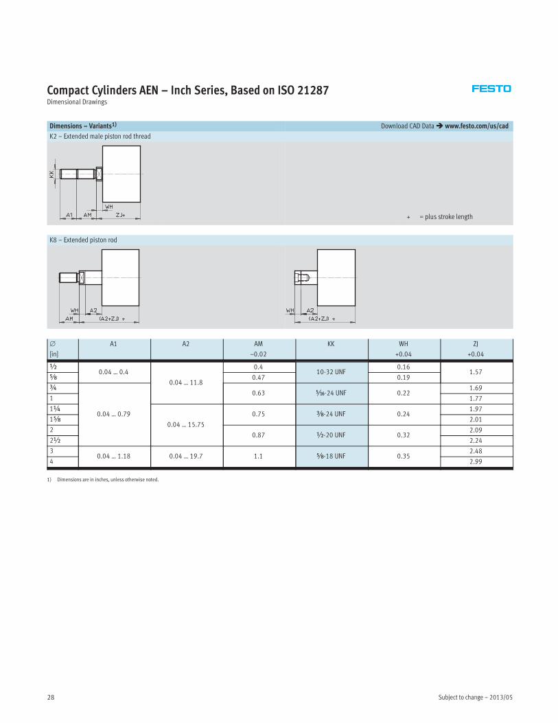
Dimensions – Variants1) Download CAD Data� www.festo.com/us/cad
Basic version
+ = plus stroke length
Z – Pulling
+ = plus stroke length
++ = plus 2x stroke length
∅ AF AM KF KK T4 WH ZJ
[in] min. –0.02 +0.04
½ 0.31 0.39 4-48 UNF10-32 UNF 0.06
0.16 1.54
Æ 0.39 0.47 8-36 UNF 0.19 1.57
¾0.55 0.63 10-32 UNF Ä-24 UNF 0.1 0.22
1.68
1 1.76
1¼0.63 0.75 Ä-24 UNF Å-24 UNF 0.13 0.24
1.98
1Æ 2.02
20.79 0.87 Ä-24 UNF ½-20 UNF 0.19 0.32
2.09
2½ 2.25
30.79 1.1 ½-20 UNF Æ-18 UNF 0.24 0.35
2.48
4 2.99
1) Dimensions are in inches, unless otherwise noted.
Subject to change – 2013/0528
Compact Cylinders AEN – Inch Series, Based on ISO 21287Dimensional Drawings
Dimensions – Variants1) Download CAD Data� www.festo.com/us/cad
K2 – Extended male piston rod thread
+ = plus stroke length
K8 – Extended piston rod
∅
[in]
A1 A2 AM
–0.02
KK WH
+0.04
ZJ
+0.04
½0.04 … 0.4
0.04 … 11.8
0.410-32 UNF
0.161.57
Æ 0.47 0.19
¾
0.04 … 0.79
0.63 Ä-24 UNF 0.221.69
1 1.77
1¼
0.04 … 15.75
0.75 Å-24 UNF 0.241.97
1Æ 2.01
20.87 ½-20 UNF 0.32
2.09
2½ 2.24
30.04 … 1.18 0.04 … 19.7 1.1 Æ-18 UNF 0.35
2.48
4 2.99
1) Dimensions are in inches, unless otherwise noted.
2013/05 – Subject to change 29
Compact Cylinders AEN – Inch Series, Based on ISO 21287Dimensional Drawings
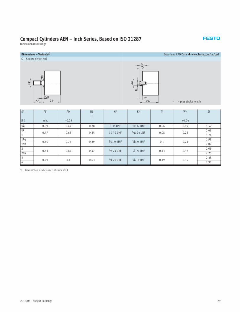
Dimensions – Variants1) Download CAD Data� www.festo.com/us/cad
Q – Square piston rod
+ = plus stroke length
∅
[in]
AF
min.
AM
–0.02
B1
�
KF KK T4 WH
+0.04
ZJ
Æ 0.39 0.47 0.28 8-36 UNF 10-32 UNF 0.06 0.19 1.57
¾0.47 0.63 0.35 10-32 UNF Ä-24 UNF 0.08 0.22
1.68
1 1.76
1¼0.55 0.75 0.39 Ä-24 UNF Å-24 UNF 0.1 0.24
1.98
1Æ 2.02
20.63 0.87 0.47 Å-24 UNF ½-20 UNF 0.13 0.32
2.09
2½ 2.25
30.79 1.1 0.63 ½-20 UNF Æ-18 UNF 0.19 0.35
2.48
4 2.99
1) Dimensions are in inches, unless otherwise noted.
Subject to change – 2013/0530
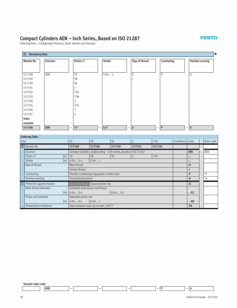
Compact Cylinders AEN – Inch Series, Based on ISO 21287Ordering Data – Configurable Products, Basic Version and Variants
Mandatory Data0M �
Module No. Function Piston∅ Stroke Type of thread Cushioning Position sensing
557188
557189
557190
557191
557192
557193
557194
557195
557196
557197
AEN ½
Æ
¾
1
1¼
1Æ
2
2½
3
4
0.04 … 1 A
I
P A
Order
example
557188 AEN – ½” – 0.4” – A – P – A
Ordering Table
Size ½ Æ ¾ 1 1¼ Conditions Code Enter code
0M Module No. 557188 557189 557190 557191 557192
Function Compact cylinder, single-acting – inch series, based on ISO 21287 AEN AEN
Piston∅ [in] ½ Æ ¾ 1 1¼ -…
Stroke [in] 0.04 … 0.4 0.04 … 1 -…
Type of thread Male thread -A
Female thread -I
Cushioning Flexible cushioning rings/pads at both ends -P -P
Position sensing Via proximity sensor -A -A
0O Protection against torsion – Square piston rod -Q
Male thread extended Extended male piston rod thread
[in] 0.04 … 0.4 0.04 … 0.8 -…K2
Piston rod extended Extended piston rod
[in] 0.04 … 0.4 0.04 … 1 -…K8
Temperature resistance Heat-resistant seals up to max. 248 °F -S6
Transfer order code
AEN – – – – P – A
2013/05 – Subject to change 31
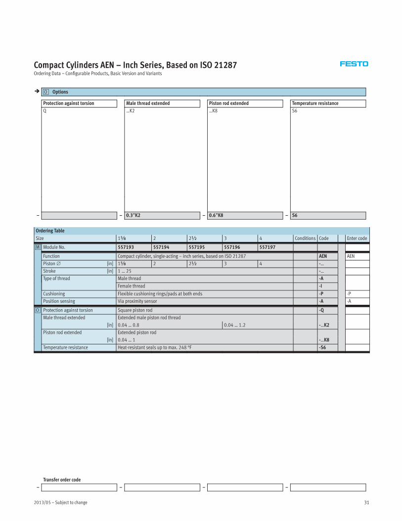
Compact Cylinders AEN – Inch Series, Based on ISO 21287Ordering Data – Configurable Products, Basic Version and Variants
� Options0O
Protection against torsion Male thread extended Piston rod extended Temperature resistance
Q …K2 …K8 S6
– – 0.3”K2 – 0.6”K8 – S6
Ordering Table
Size 1Æ 2 2½ 3 4 Conditions Code Enter code
0M Module No. 557193 557194 557195 557196 557197
Function Compact cylinder, single-acting – inch series, based on ISO 21287 AEN AEN
Piston∅ [in] 1Æ 2 2½ 3 4 -…
Stroke [in] 1 … 25 -…
Type of thread Male thread -A
Female thread -I
Cushioning Flexible cushioning rings/pads at both ends -P -P
Position sensing Via proximity sensor -A -A
0O Protection against torsion Square piston rod -Q
Male thread extended Extended male piston rod thread
[in] 0.04 … 0.8 0.04 … 1.2 -…K2
Piston rod extended Extended piston rod
[in] 0.04 … 1 -…K8
Temperature resistance Heat-resistant seals up to max. 248 °F -S6
Transfer order code
– – – –
Subject to change – 2013/0532
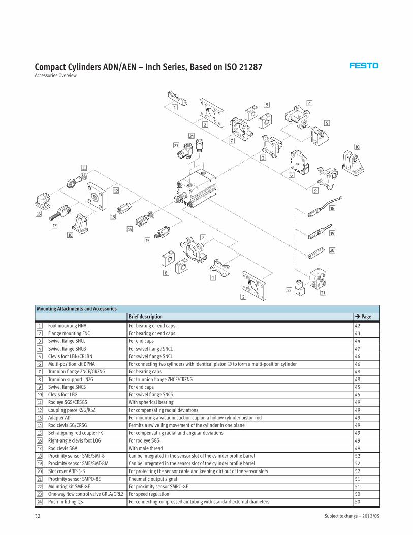
Compact Cylinders ADN/AEN – Inch Series, Based on ISO 21287Accessories Overview
1
2
3
4
5
6
8
bJ
7
9
aJ
aA
aB
aC
aD
aE
aF
aG
aH
aI
1
2
bC
bD
aJ
bB bA
7
8
Mounting Attachments and Accessories
Brief description � Page
1 Foot mounting HNA For bearing or end caps 42
2 Flange mounting FNC For bearing or end caps 43
3 Swivel flange SNCL For end caps 44
4 Swivel flange SNCB For swivel flange SNCL 47
5 Clevis foot LBN/CRLBN For swivel flange SNCL 46
6 Multi-position kit DPNA For connecting two cylinders with identical piston∅ to form a multi-position cylinder 46
7 Trunnion flange ZNCF/CRZNG For bearing caps 48
8 Trunnion support LNZG For trunnion flange ZNCF/CRZNG 48
9 Swivel flange SNCS For end caps 45
aJ Clevis foot LBG For swivel flange SNCS 45
aA Rod eye SGS/CRSGS With spherical bearing 49
aB Coupling piece KSG/KSZ For compensating radial deviations 49
aC Adapter AD For mounting a vacuum suction cup on a hollow cylinder piston rod 49
aD Rod clevis SG/CRSG Permits a swivelling movement of the cylinder in one plane 49
aE Self-aligning rod coupler FK For compensating radial and angular deviations 49
aF Right-angle clevis foot LQG For rod eye SGS 49
aG Rod clevis SGA With male thread 49
aH Proximity sensor SME/SMT-8 Can be integrated in the sensor slot of the cylinder profile barrel 52
aI Proximity sensor SME/SMT-8M Can be integrated in the sensor slot of the cylinder profile barrel 52
bJ Slot cover ABP-5-S For protecting the sensor cable and keeping dirt out of the sensor slots 52
bA Proximity sensor SMPO-8E Pneumatic output signal 51
bB Mounting kit SMB-8E For proximity sensor SMPO-8E 51
bC One-way flow control valve GRLA/GRLZ For speed regulation 50
bD Push-in fitting QS For connecting compressed air tubing with standard external diameters 50
2013/05 – Subject to change 33
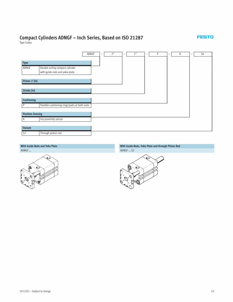
Compact Cylinders ADNGF – Inch Series, Based on ISO 21287Type Codes
ADNGF — 2” — 1” — P — A — S6
Type
ADNGF Double-acting compact cylinder
with guide rods and yoke plate
Piston∅ [in]
Stroke [in]
Cushioning
P Flexible cushioning rings/pads at both ends
Position Sensing
A Via proximity sensor
Variant
S2 Through piston rod
With Guide Rods and Yoke Plate With Guide Rods, Yoke Plate and through Piston Rod
ADNGF-… ADNGF-…-S2
Subject to change – 2013/0534
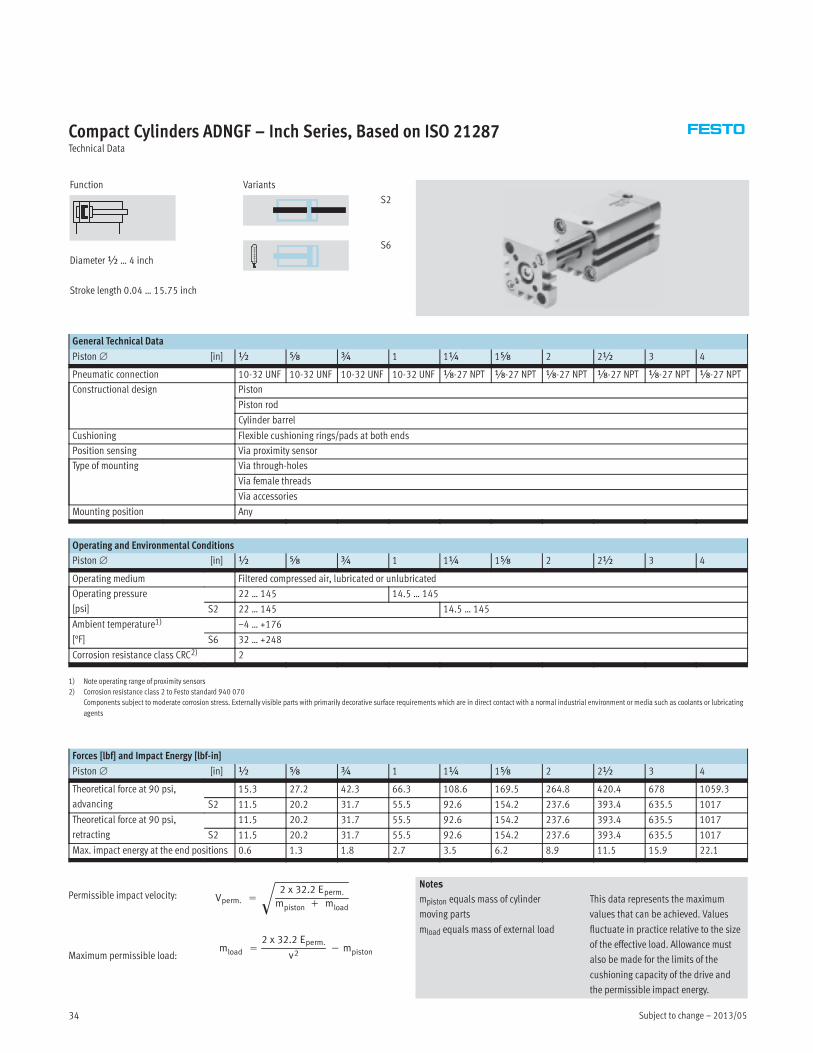
Compact Cylinders ADNGF – Inch Series, Based on ISO 21287Technical Data
Function
Diameter½ … 4 inch
Stroke length 0.04 … 15.75 inch
Variants
S2
S6
General Technical Data
Piston∅ [in] ½ Æ ¾ 1 1¼ 1Æ 2 2½ 3 4
Pneumatic connection 10-32 UNF 10-32 UNF 10-32 UNF 10-32 UNF x-27 NPT x-27 NPT x-27 NPT x-27 NPT x-27 NPT x-27 NPT
Constructional design Piston
Piston rod
Cylinder barrel
Cushioning Flexible cushioning rings/pads at both ends
Position sensing Via proximity sensor
Type of mounting Via through-holes
Via female threads
Via accessories
Mounting position Any
Operating and Environmental Conditions
Piston∅ [in] ½ Æ ¾ 1 1¼ 1Æ 2 2½ 3 4
Operating medium Filtered compressed air, lubricated or unlubricated
Operating pressure
[psi]
22 … 145 14.5 … 145
S2 22 … 145 14.5 … 145
Ambient temperature1)
[°F]
–4 … +176
S6 32 … +248
Corrosion resistance class CRC2) 2
1) Note operating range of proximity sensors
2) Corrosion resistance class 2 to Festo standard 940 070
Components subject to moderate corrosion stress. Externally visible parts with primarily decorative surface requirements which are in direct contact with a normal industrial environment or media such as coolants or lubricating
agents
Forces [lbf] and Impact Energy [lbf-in]
Piston∅ [in] ½ Æ ¾ 1 1¼ 1Æ 2 2½ 3 4
Theoretical force at 90 psi,
advancing
15.3 27.2 42.3 66.3 108.6 169.5 264.8 420.4 678 1059.3
S2 11.5 20.2 31.7 55.5 92.6 154.2 237.6 393.4 635.5 1017
Theoretical force at 90 psi,
retracting
11.5 20.2 31.7 55.5 92.6 154.2 237.6 393.4 635.5 1017
S2 11.5 20.2 31.7 55.5 92.6 154.2 237.6 393.4 635.5 1017
Max. impact energy at the end positions 0.6 1.3 1.8 2.7 3.5 6.2 8.9 11.5 15.9 22.1
Vperm. =
2 x 32.2 Eperm.
mpiston + mload�
mload =
2 x 32.2 Eperm.
v2− mpistonMaximum permissible load:
Permissible impact velocity:Notes
mpiston equals mass of cylinder
moving parts
mload equals mass of external load
This data represents the maximum
values that can be achieved. Values
fluctuate in practice relative to the size
of the effective load. Allowance must
also be made for the limits of the
cushioning capacity of the drive and
the permissible impact energy.

2013/05 – Subject to change 35
Compact Cylinders ADNGF – Inch Series, Based on ISO 21287Technical Data
Max. Lateral Force Fq as a Function of the Projection x Torque M as a Function of the Stroke Length l
x [in]
Fq[lbf]
0 0.4 0.8 1.2 1.6 2.0 2.4 2.8 3.1 3.5 3.9
45.0
40.5
36.0
31.5
27.0
22.5
18.0
13.5
9.0
4.5
00 0.4 0.8 1.2 1.6 2.0 2.4 2.8 3.1 3.5 3.9
M[lbf-in]
l [in]
177
159
142
124
106
89
71
53
35
18
0
∅ ½/Æ
∅ ¾/1
∅ 1¼
∅ 1Æ
∅ 2/2½
∅ 3/4
∅ ½/Æ
∅ ¾
∅ 1
∅ 1¼
∅ 1Æ
∅ 2
∅ 2½
∅ 3
∅ 4
Weight [lb]
Piston∅ [in] ½ Æ ¾ 1 1¼ 1Æ 2 2½ 3 4
Product weight with 0 in stroke 0.18 0.19 0.32 0.38 0.65 0.86 1.37 1.83 3.36 5.35
Additional weight per 0.4 in stroke 0.03 0.03 0.05 0.06 0.08 0.09 0.13 0.14 0.19 0.23
Moving load with 0 in stroke 0.04 0.06 0.12 0.17 0.24 0.33 0.57 0.75 1.56 2.18
Additional load per 0.4 in stroke 0.01 0.01 0.02 0.02 0.03 0.03 0.06 0.06 0.09 0.09
Materials
Sectional view
Compact cylinder Basic version S6
1 Cover Anodised aluminum
2 Cylinder barrel Anodised aluminum
3 Piston rod High-alloy steel
4 Flange screws ∅½ … Æ High-alloy steel
∅¾ … 2½ Galvanised steel
∅ 3 … 4 Standard screws, galvanised steel
– Seals Polyurethane Fluoro elastomer
1
4
132
Subject to change – 2013/0536
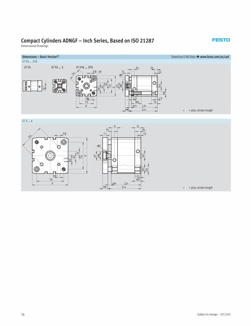
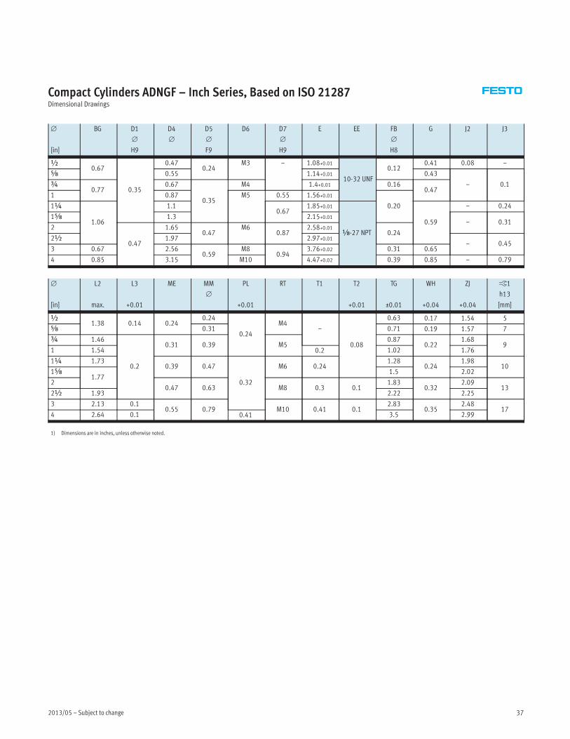
Compact Cylinders ADNGF – Inch Series, Based on ISO 21287Dimensional Drawings
Dimensions – Basic Version1) Download CAD Data� www.festo.com/us/cad
∅½ … 2½
∅ 1¼… 2½∅½… 1∅½
+ = plus stroke length
∅ 3 … 4
+ = plus stroke length
2013/05 – Subject to change 37
Compact Cylinders ADNGF – Inch Series, Based on ISO 21287Dimensional Drawings
∅
[in]
BG D1
∅
H9
D4
∅
D5
∅
F9
D6 D7
∅
H9
E EE FB
∅
H8
G J2 J3
½0.67
0.35
0.470.24
M3 – 1.08+0.01
10-32 UNF
0.120.41 0.08 –
Æ 0.55 1.14+0.01 0.43
– 0.1¾0.77
0.67
0.35
M4 1.4+0.01 0.160.47
1 0.87 M5 0.55 1.56+0.01
0.201¼
1.06
1.10.67
1.85+0.01
x-27 NPT
0.59
– 0.24
1Æ 1.3 2.15+0.01– 0.31
2
0.47
1.650.47
M60.87
2.58+0.010.24
2½ 1.97 2.97+0.01– 0.45
3 0.67 2.560.59
M80.94
3.76+0.02 0.31 0.65
4 0.85 3.15 M10 4.47+0.02 0.39 0.85 – 0.79
∅
[in]
L2
max.
L3
+0.01
ME MM
∅
PL
+0.01
RT T1 T2
+0.01
TG
±0.01
WH
+0.04
ZJ
+0.04
ß1
h13
[mm]
½1.38 0.14 0.24
0.24
0.24
M4–
0.08
0.63 0.17 1.54 5
Æ 0.31 0.71 0.19 1.57 7
¾ 1.46
0.2
0.31 0.39 M50.87
0.221.68
91 1.54 0.2 1.02 1.76
1¼ 1.730.39 0.47
0.32
M6 0.241.28
0.241.98
101Æ
1.771.5 2.02
20.47 0.63 M8 0.3 0.1
1.830.32
2.0913
2½ 1.93 2.22 2.25
3 2.13 0.10.55 0.79 M10 0.41 0.1
2.830.35
2.4817
4 2.64 0.1 0.41 3.5 2.99
1) Dimensions are in inches, unless otherwise noted.
Subject to change – 2013/0538
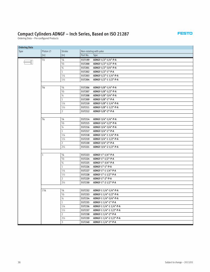
Compact Cylinders ADNGF – Inch Series, Based on ISO 21287Ordering Data – Pre-configured Products
Ordering Data
Type Piston∅ Stroke Non-rotating with yoke
[in] [in] Part No. Type
½ ¼ 557199 ADNGF-1/2”-1/4”-P-A
½ 557200 ADNGF-1/2”-1/2”-P-A
¾ 557201 ADNGF-1/2”-3/4”-P-A
1 557202 ADNGF-1/2”-1”-P-A
1¼ 557203 ADNGF-1/2”-1 1/4”-P-A
1½ 557204 ADNGF-1/2”-1 1/2”-P-A
Æ ¼ 557206 ADNGF-5/8”-1/4”-P-A
½ 557207 ADNGF-5/8”-1/2”-P-A
¾ 557208 ADNGF-5/8”-3/4”-P-A
1 557209 ADNGF-5/8”-1”-P-A
1¼ 557210 ADNGF-5/8”-1 1/4”-P-A
1½ 557211 ADNGF-5/8”-1 1/2”-P-A
2 557212 ADNGF-5/8”-2”-P-A
¾ ¼ 557214 ADNGF-3/4”-1/4”-P-A
½ 557215 ADNGF-3/4”-1/2”-P-A
¾ 557216 ADNGF-3/4”-3/4”-P-A
1 557217 ADNGF-3/4”-1”-P-A
1¼ 557218 ADNGF-3/4”-1 1/4”-P-A
1½ 557219 ADNGF-3/4”-1 1/2”-P-A
2 557220 ADNGF-3/4”-2”-P-A
2½ 557221 ADNGF-3/4”-2 1/2”-P-A
1 ¼ 557223 ADNGF-1”-1/4”-P-A
½ 557224 ADNGF-1”-1/2”-P-A
¾ 557225 ADNGF-1”-3/4”-P-A
1 557226 ADNGF-1”-1”-P-A
1¼ 557227 ADNGF-1”-1 1/4”-P-A
1½ 557228 ADNGF-1”-1 1/2”-P-A
2 557229 ADNGF-1”-2”-P-A
2½ 557230 ADNGF-1”-2 1/2”-P-A
1¼ ¼ 557232 ADNGF-1 1/4”-1/4”-P-A
½ 557233 ADNGF-1 1/4”-1/2”-P-A
¾ 557234 ADNGF-1 1/4”-3/4”-P-A
1 557235 ADNGF-1 1/4”-1”-P-A
1¼ 557236 ADNGF-1 1/4”-1 1/4”-P-A
1½ 557237 ADNGF-1 1/4”-1 1/2”-P-A
2 557238 ADNGF-1 1/4”-2”-P-A
2½ 557239 ADNGF-1 1/4”-2 1/2”-P-A
3 557240 ADNGF-1 1/4”-3”-P-A
2013/05 – Subject to change 39
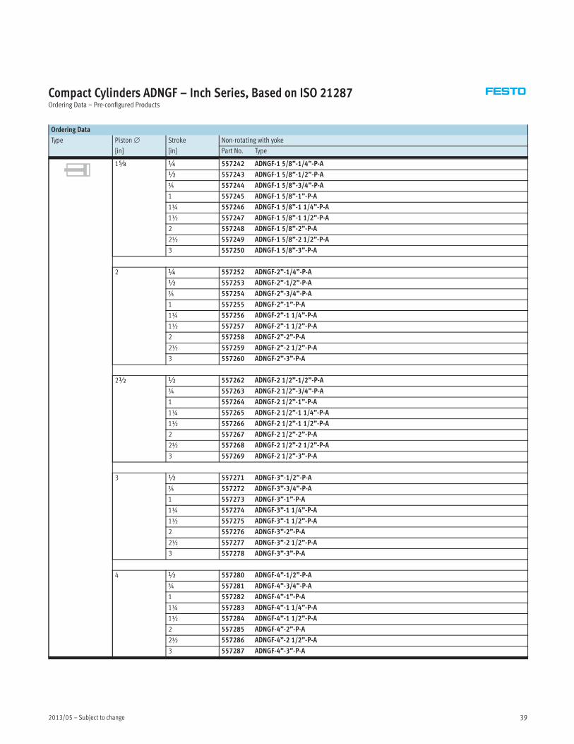
Compact Cylinders ADNGF – Inch Series, Based on ISO 21287Ordering Data – Pre-configured Products
Ordering Data
Type Piston∅ Stroke Non-rotating with yoke
[in] [in] Part No. Type
1Æ ¼ 557242 ADNGF-1 5/8”-1/4”-P-A
½ 557243 ADNGF-1 5/8”-1/2”-P-A
¾ 557244 ADNGF-1 5/8”-3/4”-P-A
1 557245 ADNGF-1 5/8”-1”-P-A
1¼ 557246 ADNGF-1 5/8”-1 1/4”-P-A
1½ 557247 ADNGF-1 5/8”-1 1/2”-P-A
2 557248 ADNGF-1 5/8”-2”-P-A
2½ 557249 ADNGF-1 5/8”-2 1/2”-P-A
3 557250 ADNGF-1 5/8”-3”-P-A
2 ¼ 557252 ADNGF-2”-1/4”-P-A
½ 557253 ADNGF-2”-1/2”-P-A
¾ 557254 ADNGF-2”-3/4”-P-A
1 557255 ADNGF-2”-1”-P-A
1¼ 557256 ADNGF-2”-1 1/4”-P-A
1½ 557257 ADNGF-2”-1 1/2”-P-A
2 557258 ADNGF-2”-2”-P-A
2½ 557259 ADNGF-2”-2 1/2”-P-A
3 557260 ADNGF-2”-3”-P-A
2½ ½ 557262 ADNGF-2 1/2”-1/2”-P-A
¾ 557263 ADNGF-2 1/2”-3/4”-P-A
1 557264 ADNGF-2 1/2”-1”-P-A
1¼ 557265 ADNGF-2 1/2”-1 1/4”-P-A
1½ 557266 ADNGF-2 1/2”-1 1/2”-P-A
2 557267 ADNGF-2 1/2”-2”-P-A
2½ 557268 ADNGF-2 1/2”-2 1/2”-P-A
3 557269 ADNGF-2 1/2”-3”-P-A
3 ½ 557271 ADNGF-3”-1/2”-P-A
¾ 557272 ADNGF-3”-3/4”-P-A
1 557273 ADNGF-3”-1”-P-A
1¼ 557274 ADNGF-3”-1 1/4”-P-A
1½ 557275 ADNGF-3”-1 1/2”-P-A
2 557276 ADNGF-3”-2”-P-A
2½ 557277 ADNGF-3”-2 1/2”-P-A
3 557278 ADNGF-3”-3”-P-A
4 ½ 557280 ADNGF-4”-1/2”-P-A
¾ 557281 ADNGF-4”-3/4”-P-A
1 557282 ADNGF-4”-1”-P-A
1¼ 557283 ADNGF-4”-1 1/4”-P-A
1½ 557284 ADNGF-4”-1 1/2”-P-A
2 557285 ADNGF-4”-2”-P-A
2½ 557286 ADNGF-4”-2 1/2”-P-A
3 557287 ADNGF-4”-3”-P-A
Subject to change – 2013/0540
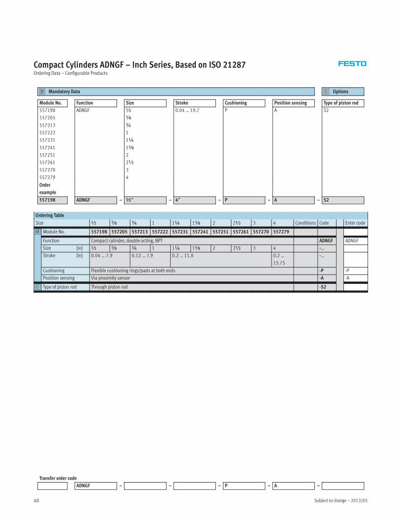
Compact Cylinders ADNGF – Inch Series, Based on ISO 21287Ordering Data – Configurable Products
Mandatory Data0M Options0O
Module No. Function Size Stroke Cushioning Position sensing Type of piston rod
557198
557205
557213
557222
557231
557241
557251
557261
557270
557279
ADNGF ½
Æ
¾
1
1¼
1Æ
2
2½
3
4
0.04 … 19.7 P A S2
Order
example
557198 ADNGF – ½” – 4” – P – A – S2
Ordering Table
Size ½ Æ ¾ 1 1¼ 1Æ 2 2½ 3 4 Conditions Code Enter code
0M Module No. 557198 557205 557213 557222 557231 557241 557251 557261 557270 557279
Function Compact cylinder, double-acting, NPT ADNGF ADNGF
Size [in] ½ Æ ¾ 1 1¼ 1Æ 2 2½ 3 4 -…
Stroke [in] 0.04 … 7.9 0.12 … 7.9 0.2 … 11.8 0.2 …
15.75
-…
Cushioning Flexible cushioning rings/pads at both ends -P -P
Position sensing Via proximity sensor -A -A
0O Type of piston rod Through piston rod -S2
Transfer order code
ADNGF – – – P – A –
2013/05 – Subject to change 41
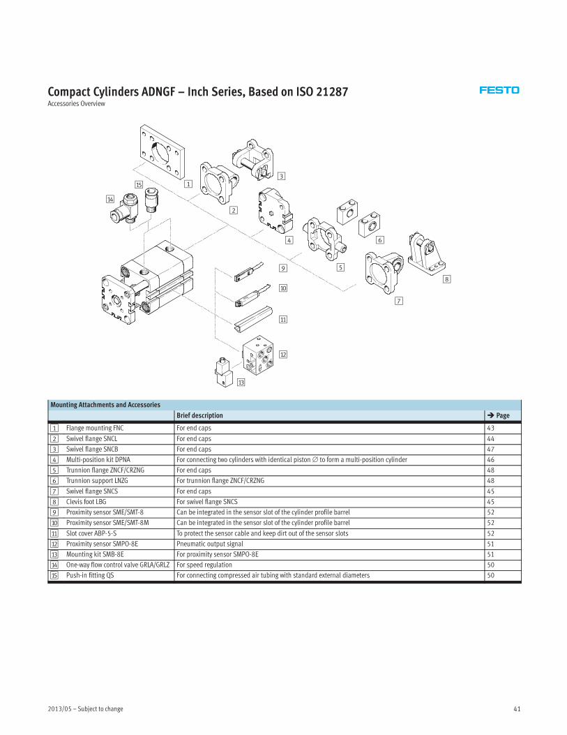
Compact Cylinders ADNGF – Inch Series, Based on ISO 21287Accessories Overview
2
4
5
6
8
7
9
aJ
aA
aD
aE 13
aB
aC
Mounting Attachments and Accessories
Brief description � Page
1 Flange mounting FNC For end caps 43
2 Swivel flange SNCL For end caps 44
3 Swivel flange SNCB For end caps 47
4 Multi-position kit DPNA For connecting two cylinders with identical piston∅ to form a multi-position cylinder 46
5 Trunnion flange ZNCF/CRZNG For end caps 48
6 Trunnion support LNZG For trunnion flange ZNCF/CRZNG 48
7 Swivel flange SNCS For end caps 45
8 Clevis foot LBG For swivel flange SNCS 45
9 Proximity sensor SME/SMT-8 Can be integrated in the sensor slot of the cylinder profile barrel 52
aJ Proximity sensor SME/SMT-8M Can be integrated in the sensor slot of the cylinder profile barrel 52
aA Slot cover ABP-5-S To protect the sensor cable and keep dirt out of the sensor slots 52
aB Proximity sensor SMPO-8E Pneumatic output signal 51
aC Mounting kit SMB-8E For proximity sensor SMPO-8E 51
aD One-way flow control valve GRLA/GRLZ For speed regulation 50
aE Push-in fitting QS For connecting compressed air tubing with standard external diameters 50
Subject to change – 2013/0542
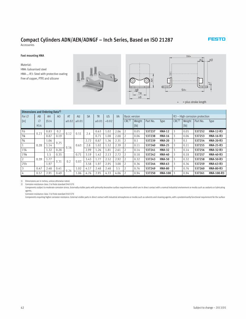
Compact Cylinders ADN/AEN/ADNGF – Inch Series, Based on ISO 21287Accessories
Foot mounting HNA
Material:
HNA: Galvanised steel
HNA-…-R3: Steel with protective coating
Free of copper, PTFE and silicone
+ = plus stroke length
Dimensions and Ordering Data1)
For∅ AB
∅
H14
AH AO AT AU SA TR US XA Basic version R3 – High corrosion protection
[in] JS14 ±0.02 ±0.01 ±0.01 −0.02 CRC2) Weight
[lb]
Part No. Type CRC2) Weight
[lb]
Part No. Type
½0.23
0.83 0.20.12 0.51 2.4
0.63 1.02 2.06 2 0.05 537237 HNA-12 3 0.05 537252 HNA-12-R3
Æ 0.87 0.19 0.71 1.08 2.08 2 0.06 537238 HNA-16 3 0.06 537253 HNA-16-R3
¾
0.28
1.060.25
0.160.63
2.72 0.87 1.36 2.31 2 0.1 537239 HNA-20 3 0.1 537254 HNA-20-R3
1 1.14 2.8 1.02 1.52 2.39 2 0.11 537240 HNA-25 3 0.11 537255 HNA-25-R3
1¼ 1.32 0.28 2.99 1.26 1.81 2.61 2 0.14 537241 HNA-32 3 0.14 537256 HNA-32-R3
1Æ
0.39
1.5 0.35 0.71 3.19 1.42 2.13 2.72 2 0.18 537242 HNA-40 3 0.18 537257 HNA-40-R3
2 1.770.31 0.2 0.83
3.43 1.77 2.52 2.92 2 0.32 537243 HNA-50 3 0.32 537258 HNA-50-R3
2½ 1.97 3.58 1.97 2.95 3.08 2 0.36 537244 HNA-63 3 0.36 537259 HNA-63-R3
3 0.47 2.48 0.410.24
1.02 4.17 2.48 2.48 3.5 2 0.76 537249 HNA-80 3 0.76 537260 HNA-80-R3
4 0.57 2.91 0.49 1.06 4.76 2.95 4.33 4.06 2 0.94 537250 HNA-100 3 0.94 537261 HNA-100-R3
1) Dimensions are in inches, unless otherwise noted.
2) Corrosion resistance class 2 to Festo standard 940 070
Components subject to moderate corrosion stress. Externally visible parts with primarily decorative surface requirements which are in direct contact with a normal industrial environment or media such as coolants or lubricating
agents.
Corrosion resistance class 3 to Festo standard 940 070
Components requiring higher corrosion resistance. External visible parts in direct contact with industrial atmospheres or media such as solvents and cleaning agents, with a predominantly functional requirement for the surface

2013/05 – Subject to change 43
Compact Cylinders ADN/AEN/ADNGF – Inch Series, Based on ISO 21287Accessories
Flange mounting FNC
Material:
Galvanised steel
Free of copper, PTFE and silicone
+ = plus stroke length
∅ 1¼… 5∅½… 1
Dimensions and Ordering Data1)
For∅ E FB
∅
MF R TF UF ZF CRC2) Weight Part No. Type
[in] ±0.4 [lb]
½ 1.10.22
0.31 –
1.57 1.97 1.86 2 0.16 537245 FNC-12
Æ 1.14 1.69 2.17 1.89 2 0.18 537246 FNC-16
¾ 1.420.26
2.17 2.76 2.0 2 0.29 537247 FNC-20
1 1.57 2.36 2.99 2.07 2 0.34 537248 FNC-25
1¼ 1.77 0.280.39
1.26 2.52 3.15 2.37 2 0.48 174376 FNC-32
1Æ 2.13
0.35
1.42 2.83 3.54 2.41 2 0.56 174377 FNC-40
2 2.560.47
1.77 3.54 4.33 2.57 2 1.04 174378 FNC-50
2½ 2.95 1.97 3.94 4.72 2.72 2 1.38 174379 FNC-63
3 3.66 0.470.63
2.48 4.96 5.91 3.11 2 3.3 174380 FNC-80
4 4.33 0.55 2.95 5.91 6.89 3.62 2 4.8 174381 FNC-100
5 5.2 0.63 0.79 3.54 7.09 8.27 4.41 2 7.5 174382 FNC-125
1) Dimensions are in inches, unless otherwise noted.
2) Corrosion resistance class 2 to Festo standard 940 070
Components subject to moderate corrosion stress. Externally visible parts with primarily decorative surface requirements which are in direct contact with a normal industrial environment or media such as coolants or lubricating
agents.
Subject to change – 2013/0544
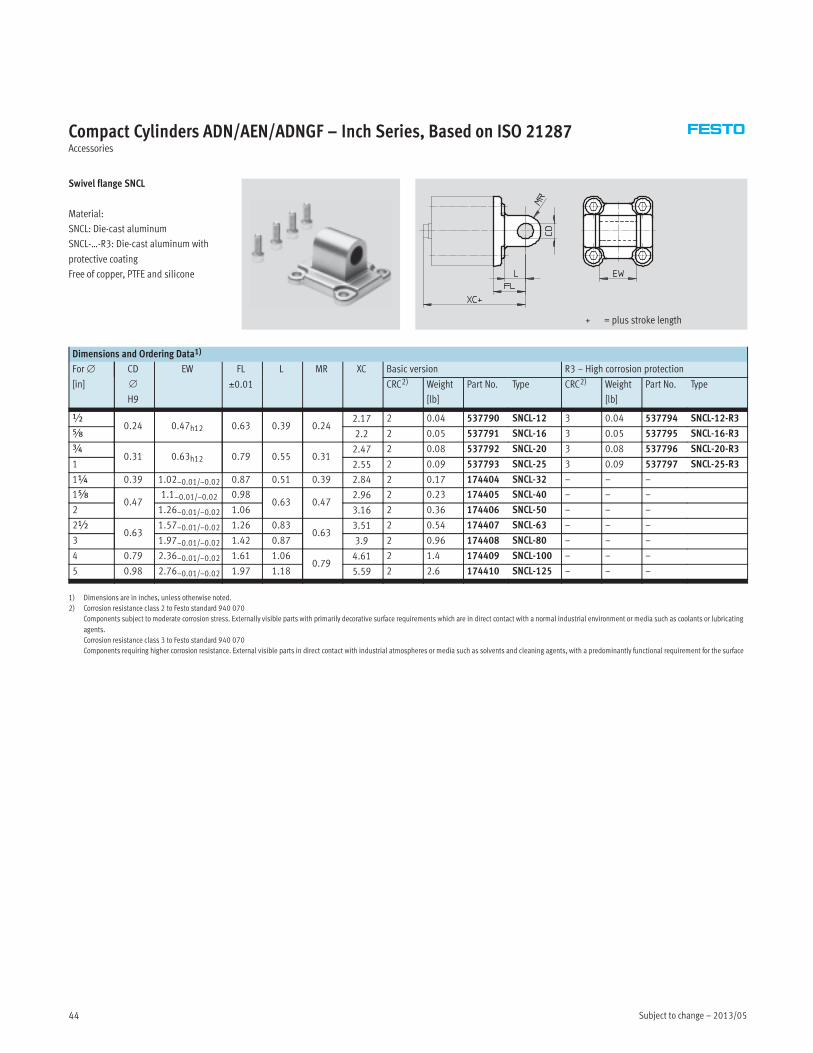
Compact Cylinders ADN/AEN/ADNGF – Inch Series, Based on ISO 21287Accessories
Swivel flange SNCL
Material:
SNCL: Die-cast aluminum
SNCL-…-R3: Die-cast aluminum with
protective coating
Free of copper, PTFE and silicone
+ = plus stroke length
Dimensions and Ordering Data1)
For∅ CD
∅
H9
EW FL L MR XC Basic version R3 – High corrosion protection
[in] ±0.01 CRC2) Weight
[lb]
Part No. Type CRC2) Weight
[lb]
Part No. Type
½0.24 0.47h12 0.63 0.39 0.24
2.17 2 0.04 537790 SNCL-12 3 0.04 537794 SNCL-12-R3
Æ 2.2 2 0.05 537791 SNCL-16 3 0.05 537795 SNCL-16-R3
¾0.31 0.63h12 0.79 0.55 0.31
2.47 2 0.08 537792 SNCL-20 3 0.08 537796 SNCL-20-R3
1 2.55 2 0.09 537793 SNCL-25 3 0.09 537797 SNCL-25-R3
1¼ 0.39 1.02–0.01/–0.02 0.87 0.51 0.39 2.84 2 0.17 174404 SNCL-32 – – –
1Æ0.47
1.1–0.01/–0.02 0.980.63 0.47
2.96 2 0.23 174405 SNCL-40 – – –
2 1.26–0.01/–0.02 1.06 3.16 2 0.36 174406 SNCL-50 – – –
2½0.63
1.57–0.01/–0.02 1.26 0.830.63
3.51 2 0.54 174407 SNCL-63 – – –
3 1.97–0.01/–0.02 1.42 0.87 3.9 2 0.96 174408 SNCL-80 – – –
4 0.79 2.36–0.01/–0.02 1.61 1.060.79
4.61 2 1.4 174409 SNCL-100 – – –
5 0.98 2.76–0.01/–0.02 1.97 1.18 5.59 2 2.6 174410 SNCL-125 – – –
1) Dimensions are in inches, unless otherwise noted.
2) Corrosion resistance class 2 to Festo standard 940 070
Components subject to moderate corrosion stress. Externally visible parts with primarily decorative surface requirements which are in direct contact with a normal industrial environment or media such as coolants or lubricating
agents.
Corrosion resistance class 3 to Festo standard 940 070
Components requiring higher corrosion resistance. External visible parts in direct contact with industrial atmospheres or media such as solvents and cleaning agents, with a predominantly functional requirement for the surface
2013/05 – Subject to change 45
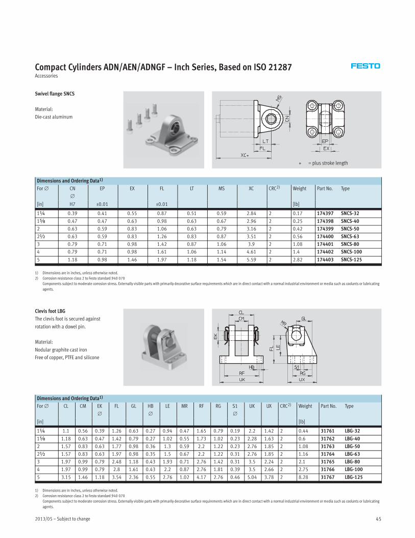
Compact Cylinders ADN/AEN/ADNGF – Inch Series, Based on ISO 21287Accessories
Swivel flange SNCS
Material:
Die-cast aluminum
+ = plus stroke length
Dimensions and Ordering Data1)
For∅ CN
∅
EP EX FL LT MS XC CRC2) Weight Part No. Type
[in] H7 ±0.01 ±0.01 [lb]
1¼ 0.39 0.41 0.55 0.87 0.51 0.59 2.84 2 0.17 174397 SNCS-32
1Æ 0.47 0.47 0.63 0.98 0.63 0.67 2.96 2 0.25 174398 SNCS-40
2 0.63 0.59 0.83 1.06 0.63 0.79 3.16 2 0.42 174399 SNCS-50
2½ 0.63 0.59 0.83 1.26 0.83 0.87 3.51 2 0.56 174400 SNCS-63
3 0.79 0.71 0.98 1.42 0.87 1.06 3.9 2 1.08 174401 SNCS-80
4 0.79 0.71 0.98 1.61 1.06 1.14 4.61 2 1.4 174402 SNCS-100
5 1.18 0.98 1.46 1.97 1.18 1.54 5.59 2 2.82 174403 SNCS-125
1) Dimensions are in inches, unless otherwise noted.
2) Corrosion resistance class 2 to Festo standard 940 070
Components subject to moderate corrosion stress. Externally visible parts with primarily decorative surface requirements which are in direct contact with a normal industrial environment or media such as coolants or lubricating
agents.
Clevis foot LBG
The clevis foot is secured against
rotation with a dowel pin.
Material:
Nodular graphite cast iron
Free of copper, PTFE and silicone
Dimensions and Ordering Data1)
For∅ CL CM EK
∅
FL GL HB
∅
LE MR RF RG S1
∅
UK UX CRC2) Weight Part No. Type
[in] [lb]
1¼ 1.1 0.56 0.39 1.26 0.63 0.27 0.94 0.47 1.65 0.79 0.19 2.2 1.42 2 0.44 31761 LBG-32
1Æ 1.18 0.63 0.47 1.42 0.79 0.27 1.02 0.55 1.73 1.02 0.23 2.28 1.63 2 0.6 31762 LBG-40
2 1.57 0.83 0.63 1.77 0.98 0.36 1.3 0.59 2.2 1.22 0.23 2.76 1.85 2 1.08 31763 LBG-50
2½ 1.57 0.83 0.63 1.97 0.98 0.35 1.5 0.67 2.2 1.22 0.31 2.76 1.85 2 1.16 31764 LBG-63
3 1.97 0.99 0.79 2.48 1.18 0.43 1.93 0.71 2.76 1.42 0.31 3.5 2.24 2 2.1 31765 LBG-80
4 1.97 0.99 0.79 2.8 1.61 0.43 2.2 0.87 2.76 1.81 0.39 3.5 2.66 2 2.75 31766 LBG-100
5 3.15 1.46 1.18 3.54 2.36 0.55 2.76 1.02 4.17 2.76 0.46 5.04 3.78 2 8.28 31767 LBG-125
1) Dimensions are in inches, unless otherwise noted.
2) Corrosion resistance class 2 to Festo standard 940 070
Components subject to moderate corrosion stress. Externally visible parts with primarily decorative surface requirements which are in direct contact with a normal industrial environment or media such as coolants or lubricating
agents.
Subject to change – 2013/0546
Compact Cylinders ADN/AEN/ADNGF – Inch Series, Based on ISO 21287Accessories
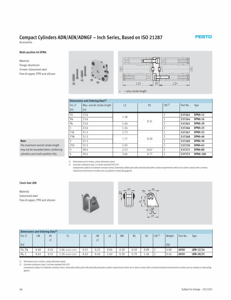
Multi-position kit DPNA
Material:
Flange: Aluminum
Screws: Galvanised steel
Free of copper, PTFE and silicone
+ = plus stroke length
Dimensions and Ordering Data1)
For∅ Max. overall stroke length L2 B1 CRC2) Part No. Type
[in] [in]
½ 23.61.38
0.51
2 537263 DPNA-12
Æ 23.6 2 537264 DPNA-16
¾ 23.6 1.46 2 537265 DPNA-20
1 23.6 1.54 2 537266 DPNA-25
1¼ 31.5 1.73
0.59
2 537267 DPNA-32
1Æ 31.51.77
2 537268 DPNA-40
Note
The maximum overall stroke length
may not be exceeded when combining
cylinders and multi-position kits.
2 31.5 2 537269 DPNA-50
2½ 31.5 1.93 2 537270 DPNA-63
3 39.4 2.13 0.67 2 537271 DPNA-80
4 39.4 2.64 0.77 2 537272 DPNA-100
1) Dimensions are in inches, unless otherwise noted.
2) Corrosion resistance class 2 to Festo standard 940 070
Components subject to moderate corrosion stress. Externally visible parts with primarily decorative surface requirements which are in direct contact with a normal
industrial environment or media such as coolants or lubricating agents.
Clevis foot LBN
Material:
Galvanised steel
Free of copper, PTFE and silicone
Dimensions and Ordering Data1)
For∅ CM EK
∅
FL GL HB
∅
LE MR RG UX CRC1) Weight Part No. Type
[in] [lb]
½,Æ 0.48 0.24 1.06 +0.01/–0.01 0.51 0.22 0.94 0.28 0.59 0.98 2 0.08 6058 LBN-12/16
¾, 1 0.63 0.31 1.18 +0.02/–0.01 0.63 0.26 1.02 0.39 0.79 1.26 2 0.16 6059 LBN-20/25
1) Dimensions are in inches, unless otherwise noted.
2) Corrosion resistance class 2 to Festo standard 940 070
Components subject to moderate corrosion stress. Externally visible parts with primarily decorative surface requirements which are in direct contact with a normal industrial environment or media such as coolants or lubricating
agents.
2013/05 – Subject to change 47
Compact Cylinders ADN/AEN/ADNGF – Inch Series, Based on ISO 21287Accessories
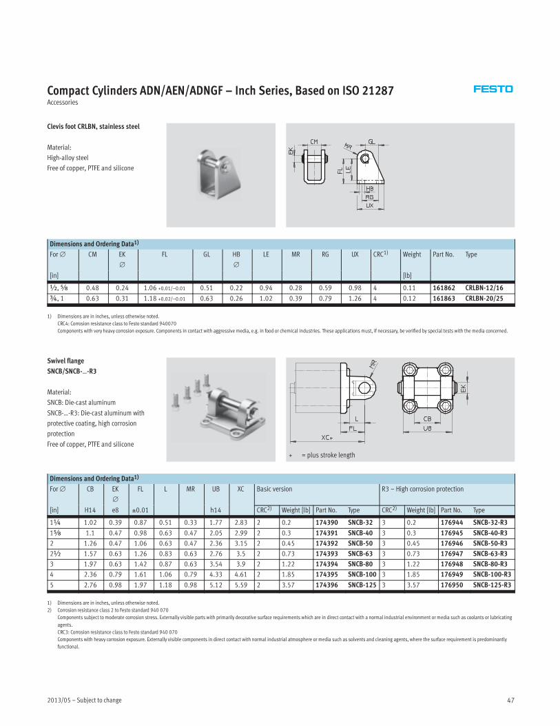
Clevis foot CRLBN, stainless steel
Material:
High-alloy steel
Free of copper, PTFE and silicone
Dimensions and Ordering Data1)
For∅ CM EK
∅
FL GL HB
∅
LE MR RG UX CRC1) Weight Part No. Type
[in] [lb]
½,Æ 0.48 0.24 1.06 +0.01/–0.01 0.51 0.22 0.94 0.28 0.59 0.98 4 0.11 161862 CRLBN-12/16
¾, 1 0.63 0.31 1.18 +0.02/–0.01 0.63 0.26 1.02 0.39 0.79 1.26 4 0.12 161863 CRLBN-20/25
1) Dimensions are in inches, unless otherwise noted.
CRC4: Corrosion resistance class to Festo standard 940070
Components with very heavy corrosion exposure. Components in contact with aggressive media, e.g. in food or chemical industries. These applications must, if necessary, be verified by special tests with the media concerned.
Swivel flange
SNCB/SNCB-…-R3
Material:
SNCB: Die-cast aluminum
SNCB-…-R3: Die-cast aluminum with
protective coating, high corrosion
protection
Free of copper, PTFE and silicone
+ = plus stroke length
Dimensions and Ordering Data1)
For∅ CB EK
∅
FL L MR UB XC Basic version R3 – High corrosion protection
[in] H14 e8 ±0.01 h14 CRC2) Weight [lb] Part No. Type CRC2) Weight [lb] Part No. Type
1¼ 1.02 0.39 0.87 0.51 0.33 1.77 2.83 2 0.2 174390 SNCB-32 3 0.2 176944 SNCB-32-R3
1Æ 1.1 0.47 0.98 0.63 0.47 2.05 2.99 2 0.3 174391 SNCB-40 3 0.3 176945 SNCB-40-R3
2 1.26 0.47 1.06 0.63 0.47 2.36 3.15 2 0.45 174392 SNCB-50 3 0.45 176946 SNCB-50-R3
2½ 1.57 0.63 1.26 0.83 0.63 2.76 3.5 2 0.73 174393 SNCB-63 3 0.73 176947 SNCB-63-R3
3 1.97 0.63 1.42 0.87 0.63 3.54 3.9 2 1.22 174394 SNCB-80 3 1.22 176948 SNCB-80-R3
4 2.36 0.79 1.61 1.06 0.79 4.33 4.61 2 1.85 174395 SNCB-100 3 1.85 176949 SNCB-100-R3
5 2.76 0.98 1.97 1.18 0.98 5.12 5.59 2 3.57 174396 SNCB-125 3 3.57 176950 SNCB-125-R3
1) Dimensions are in inches, unless otherwise noted.
2) Corrosion resistance class 2 to Festo standard 940 070
Components subject to moderate corrosion stress. Externally visible parts with primarily decorative surface requirements which are in direct contact with a normal industrial environment or media such as coolants or lubricating
agents.
CRC3: Corrosion resistance class to Festo standard 940 070
Components with heavy corrosion exposure. Externally visible components in direct contact with normal industrial atmosphere or media such as solvents and cleaning agents, where the surface requirement is predominantly
functional.
Subject to change – 2013/0548
Compact Cylinders ADN/AEN/ADNGF – Inch Series, Based on ISO 21287Accessories
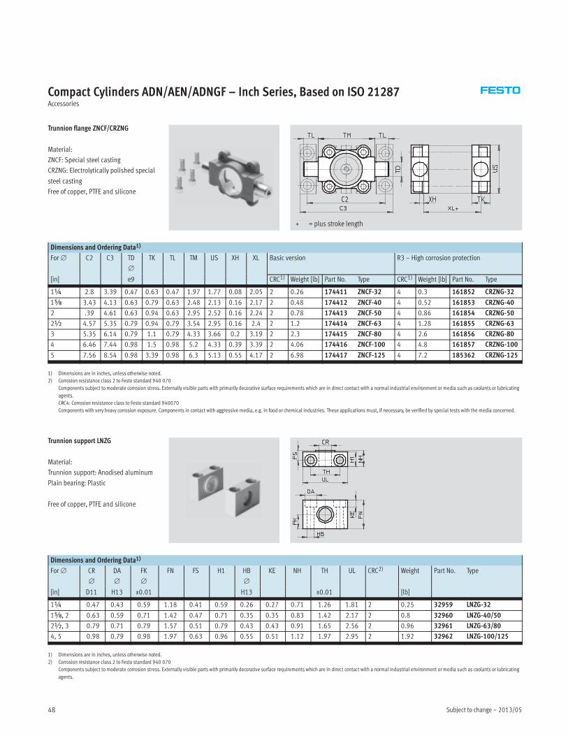
Trunnion flange ZNCF/CRZNG
Material:
ZNCF: Special steel casting
CRZNG: Electrolytically polished special
steel casting
Free of copper, PTFE and silicone
+ = plus stroke length
Dimensions and Ordering Data1)
For∅ C2 C3 TD
∅
TK TL TM US XH XL Basic version R3 – High corrosion protection
[in] e9 CRC1) Weight [lb] Part No. Type CRC1) Weight [lb] Part No. Type
1¼ 2.8 3.39 0.47 0.63 0.47 1.97 1.77 0.08 2.05 2 0.26 174411 ZNCF-32 4 0.3 161852 CRZNG-32
1Æ 3.43 4.13 0.63 0.79 0.63 2.48 2.13 0.16 2.17 2 0.48 174412 ZNCF-40 4 0.52 161853 CRZNG-40
2 .39 4.61 0.63 0.94 0.63 2.95 2.52 0.16 2.24 2 0.78 174413 ZNCF-50 4 0.86 161854 CRZNG-50
2½ 4.57 5.35 0.79 0.94 0.79 3.54 2.95 0.16 2.4 2 1.2 174414 ZNCF-63 4 1.28 161855 CRZNG-63
3 5.35 6.14 0.79 1.1 0.79 4.33 3.66 0.2 3.19 2 2.3 174415 ZNCF-80 4 2.6 161856 CRZNG-80
4 6.46 7.44 0.98 1.5 0.98 5.2 4.33 0.39 3.39 2 4.06 174416 ZNCF-100 4 4.8 161857 CRZNG-100
5 7.56 8.54 0.98 3.39 0.98 6.3 5.13 0.55 4.17 2 6.98 174417 ZNCF-125 4 7.2 185362 CRZNG-125
1) Dimensions are in inches, unless otherwise noted.
2) Corrosion resistance class 2 to Festo standard 940 070
Components subject to moderate corrosion stress. Externally visible parts with primarily decorative surface requirements which are in direct contact with a normal industrial environment or media such as coolants or lubricating
agents.
CRC4: Corrosion resistance class to Festo standard 940070
Components with very heavy corrosion exposure. Components in contact with aggressive media, e.g. in food or chemical industries. These applications must, if necessary, be verified by special tests with the media concerned.
Trunnion support LNZG
Material:
Trunnion support: Anodised aluminum
Plain bearing: Plastic
Free of copper, PTFE and silicone
Dimensions and Ordering Data1)
For∅ CR
∅
DA
∅
FK
∅
FN FS H1 HB
∅
KE NH TH UL CRC2) Weight Part No. Type
[in] D11 H13 ±0.01 H13 ±0.01 [lb]
1¼ 0.47 0.43 0.59 1.18 0.41 0.59 0.26 0.27 0.71 1.26 1.81 2 0.25 32959 LNZG-32
1Æ, 2 0.63 0.59 0.71 1.42 0.47 0.71 0.35 0.35 0.83 1.42 2.17 2 0.8 32960 LNZG-40/50
2½, 3 0.79 0.71 0.79 1.57 0.51 0.79 0.43 0.43 0.91 1.65 2.56 2 0.96 32961 LNZG-63/80
4, 5 0.98 0.79 0.98 1.97 0.63 0.96 0.55 0.51 1.12 1.97 2.95 2 1.92 32962 LNZG-100/125
1) Dimensions are in inches, unless otherwise noted.
2) Corrosion resistance class 2 to Festo standard 940 070
Components subject to moderate corrosion stress. Externally visible parts with primarily decorative surface requirements which are in direct contact with a normal industrial environment or media such as coolants or lubricating
agents.
2013/05 – Subject to change 49
Compact Cylinders ADN/AEN/ADNGF – Inch Series, Based on ISO 21287Accessories
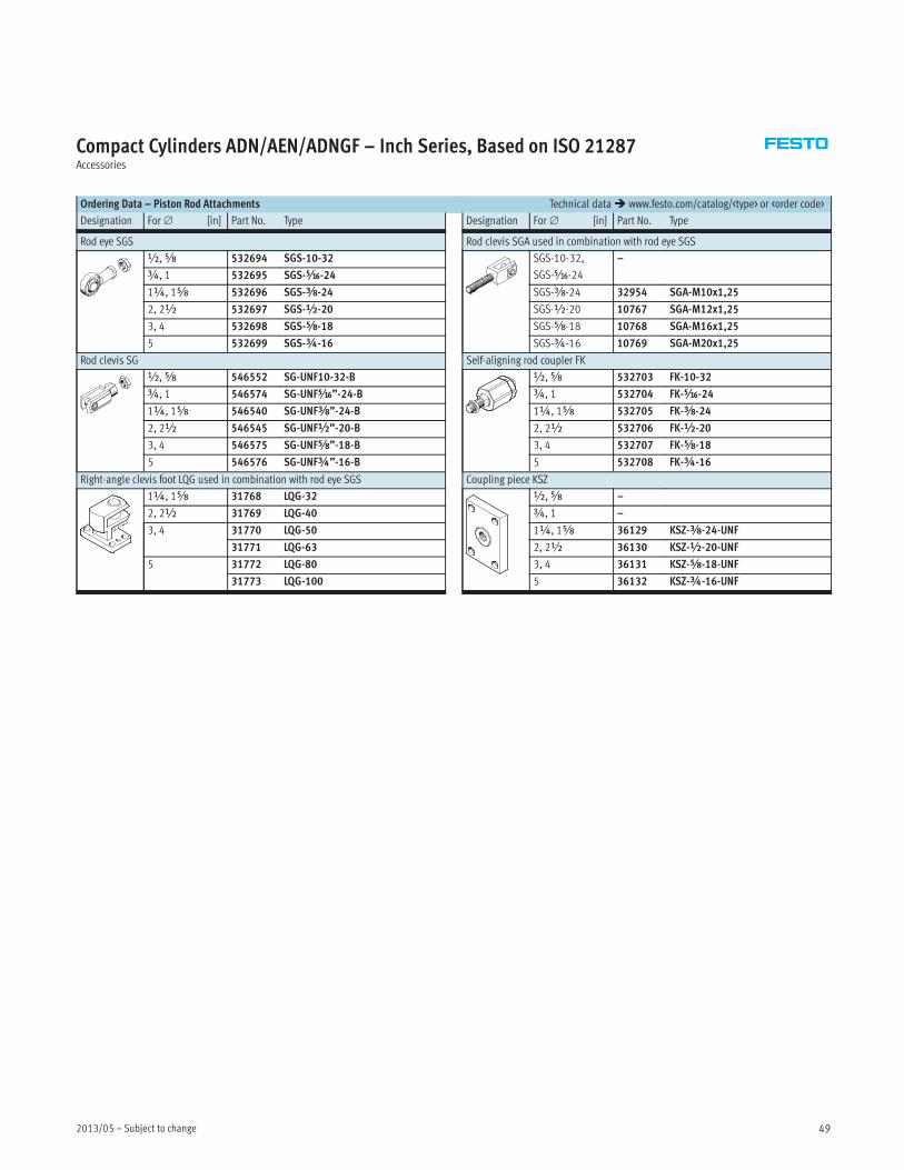
Ordering Data – Piston Rod Attachments Technical data� www.festo.com/catalog/<type> or <order code>
Designation For∅ [in] Part No. Type Designation For∅ [in] Part No. Type
Rod eye SGS
½,Æ 532694 SGS-10-32
¾, 1 532695 SGS-Ä-24
1¼, 1Æ 532696 SGS-Å-24
2, 2½ 532697 SGS-½-20
3, 4 532698 SGS-Æ-18
5 532699 SGS-¾-16
Rod clevis SG
½,Æ 546552 SG-UNF10-32-B
¾, 1 546574 SG-UNFÄ”-24-B
1¼, 1Æ 546540 SG-UNFÅ”-24-B
2, 2½ 546545 SG-UNF½”-20-B
3, 4 546575 SG-UNFÆ”-18-B
5 546576 SG-UNF¾”-16-B
Right-angle clevis foot LQG used in combination with rod eye SGS
1¼, 1Æ 31768 LQG-32
2, 2½ 31769 LQG-40
3, 4 31770 LQG-50
31771 LQG-63
5 31772 LQG-80
31773 LQG-100
Rod clevis SGA used in combination with rod eye SGS
SGS-10-32,
SGS-Ä-24
–
SGS-Å-24 32954 SGA-M10x1,25
SGS-½-20 10767 SGA-M12x1,25
SGS-Æ-18 10768 SGA-M16x1,25
SGS-¾-16 10769 SGA-M20x1,25
Self-aligning rod coupler FK
½,Æ 532703 FK-10-32
¾, 1 532704 FK-Ä-24
1¼, 1Æ 532705 FK-Å-24
2, 2½ 532706 FK-½-20
3, 4 532707 FK-Æ-18
5 532708 FK-¾-16
Coupling piece KSZ
½,Æ –
¾, 1 –
1¼, 1Æ 36129 KSZ-Å-24-UNF
2, 2½ 36130 KSZ-½-20-UNF
3, 4 36131 KSZ-Æ-18-UNF
5 36132 KSZ-¾-16-UNF
Subject to change – 2013/0550
Compact Cylinders ADN/AEN/ADNGF – Inch Series, Based on ISO 21287Accessories
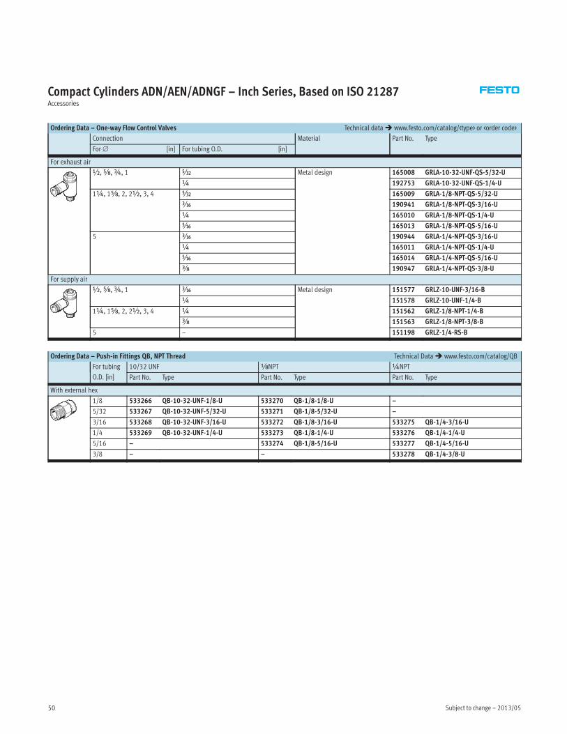
Ordering Data – One-way Flow Control Valves Technical data� www.festo.com/catalog/<type> or <order code>
Connection Material Part No. Type
For∅ [in] For tubing O.D. [in]
For exhaust air
½,Æ,¾, 1 Â Metal design 165008 GRLA-10-32-UNF-QS-5/32-U
¼ 192753 GRLA-10-32-UNF-QS-1/4-U
1¼, 1Æ, 2, 2½, 3, 4 Â 165009 GRLA-1/8-NPT-QS-5/32-U
à 190941 GRLA-1/8-NPT-QS-3/16-U
¼ 165010 GRLA-1/8-NPT-QS-1/4-U
Ä 165013 GRLA-1/8-NPT-QS-5/16-U
5 Ã 190944 GRLA-1/4-NPT-QS-3/16-U
¼ 165011 GRLA-1/4-NPT-QS-1/4-U
Ä 165014 GRLA-1/4-NPT-QS-5/16-U
y 190947 GRLA-1/4-NPT-QS-3/8-U
For supply air
½,Æ,¾, 1 Ã Metal design 151577 GRLZ-10-UNF-3/16-B
¼ 151578 GRLZ-10-UNF-1/4-B
1¼, 1Æ, 2, 2½, 3, 4 ¼ 151562 GRLZ-1/8-NPT-1/4-B
y 151563 GRLZ-1/8-NPT-3/8-B
5 – 151198 GRLZ-1/4-RS-B
Ordering Data – Push-in Fittings QB, NPT Thread Technical Data� www.festo.com/catalog/QB
For tubing
O.D. [in]
10/32 UNF xNPT ¼NPT
Part No. Type Part No. Type Part No. Type
With external hex
1/8 533266 QB-10-32-UNF-1/8-U 533270 QB-1/8-1/8-U –
5/32 533267 QB-10-32-UNF-5/32-U 533271 QB-1/8-5/32-U –
3/16 533268 QB-10-32-UNF-3/16-U 533272 QB-1/8-3/16-U 533275 QB-1/4-3/16-U
1/4 533269 QB-10-32-UNF-1/4-U 533273 QB-1/8-1/4-U 533276 QB-1/4-1/4-U
5/16 – 533274 QB-1/8-5/16-U 533277 QB-1/4-5/16-U
3/8 – – 533278 QB-1/4-3/8-U
2013/05 – Subject to change 51
Compact Cylinders ADN/AEN/ADNGF – Inch Series, Based on ISO 21287Accessories
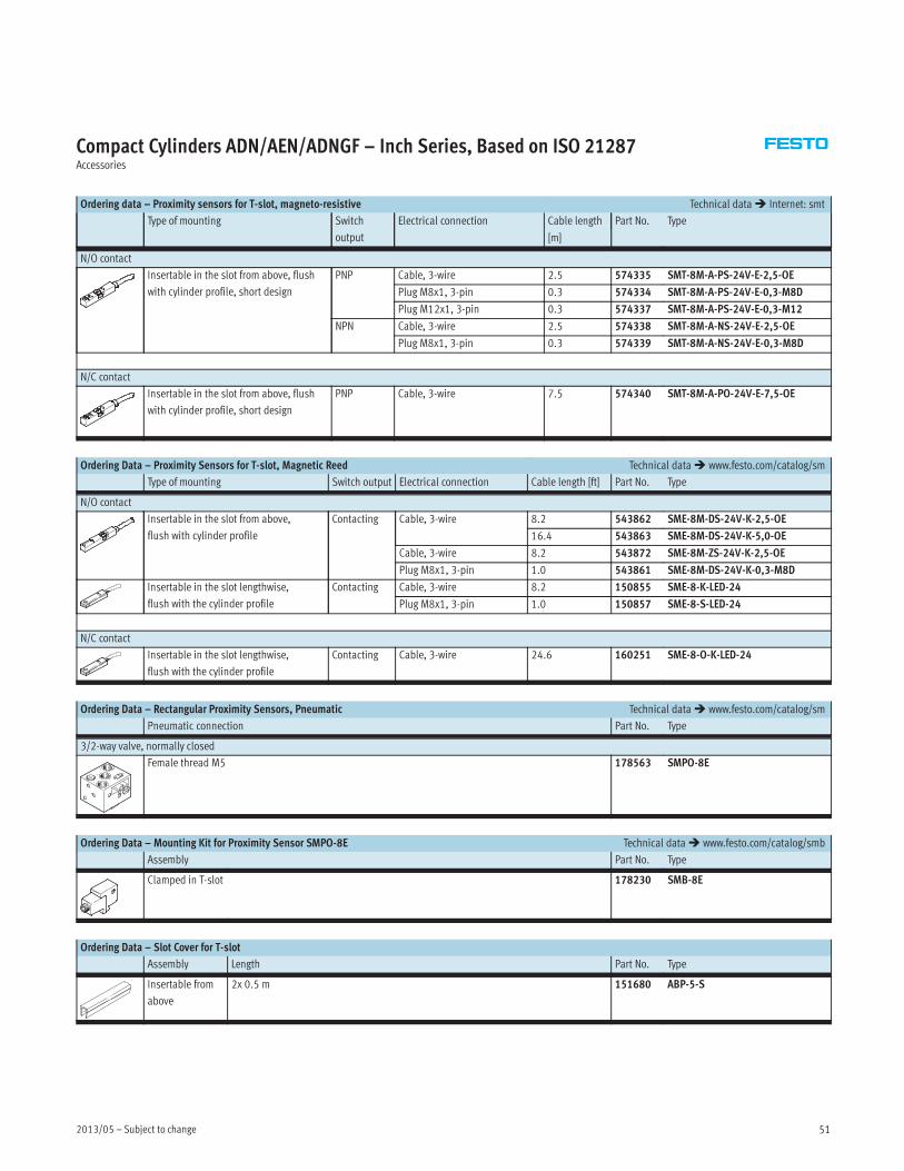
Ordering data – Proximity sensors for T-slot, magneto-resistive Technical data� Internet: smt
Type of mounting Switch
output
Electrical connection Cable length Part No. Type
[m]
N/O contact
Insertable in the slot from above, flush
with cylinder profile, short design
PNP Cable, 3-wire 2.5 574335 SMT-8M-A-PS-24V-E-2,5-OE
Plug M8x1, 3-pin 0.3 574334 SMT-8M-A-PS-24V-E-0,3-M8D
Plug M12x1, 3-pin 0.3 574337 SMT-8M-A-PS-24V-E-0,3-M12
NPN Cable, 3-wire 2.5 574338 SMT-8M-A-NS-24V-E-2,5-OE
Plug M8x1, 3-pin 0.3 574339 SMT-8M-A-NS-24V-E-0,3-M8D
N/C contact
Insertable in the slot from above, flush
with cylinder profile, short design
PNP Cable, 3-wire 7.5 574340 SMT-8M-A-PO-24V-E-7,5-OE
Ordering Data – Proximity Sensors for T-slot, Magnetic Reed Technical data� www.festo.com/catalog/sm
Type of mounting Switch output Electrical connection Cable length [ft] Part No. Type
N/O contact
Insertable in the slot from above,
flush with cylinder profile
Contacting Cable, 3-wire 8.2 543862 SME-8M-DS-24V-K-2,5-OE
16.4 543863 SME-8M-DS-24V-K-5,0-OE
Cable, 3-wire 8.2 543872 SME-8M-ZS-24V-K-2,5-OE
Plug M8x1, 3-pin 1.0 543861 SME-8M-DS-24V-K-0,3-M8D
Insertable in the slot lengthwise,
flush with the cylinder profile
Contacting Cable, 3-wire 8.2 150855 SME-8-K-LED-24
Plug M8x1, 3-pin 1.0 150857 SME-8-S-LED-24
N/C contact
Insertable in the slot lengthwise,
flush with the cylinder profile
Contacting Cable, 3-wire 24.6 160251 SME-8-O-K-LED-24
Ordering Data – Rectangular Proximity Sensors, Pneumatic Technical data� www.festo.com/catalog/sm
Pneumatic connection Part No. Type
3/2-way valve, normally closed
Female thread M5 178563 SMPO-8E
Ordering Data – Mounting Kit for Proximity Sensor SMPO-8E Technical data� www.festo.com/catalog/smb
Assembly Part No. Type
Clamped in T-slot 178230 SMB-8E
Ordering Data – Slot Cover for T-slot
Assembly Length Part No. Type
Insertable from
above
2x 0.5 m 151680 ABP-5-S

Subject to change – 2013/0552
Compact Cylinders ADN/AEN/ADNGF – Inch Series, Based on ISO 21287Accessories
Ordering Data – Connecting Cables Technical data� www.festo.com/catalog/nebu
Electrical connection, left Electrical connection, right Cable length [ft] Part No. Type
Straight socket, M8x1, 3-pin Cable, open end, 3-wire 8.2 541333 NEBU-M8G3-K-2.5-LE3
16.4 541334 NEBU-M8G3-K-5-LE3
Straight socket, M12x1, 5-pin Cable, open end, 3-wire 8.2 541363 NEBU-M12G5-K-2.5-LE3
16.4 541364 NEBU-M12G5-K-5-LE3
Angled socket, M8x1, 3-pin Cable, open end, 3-wire 8.2 541338 NEBU-M8W3-K-2.5-LE3
16.4 541341 NEBU-M8W3-K-5-LE3
Angled socket, M12x1, 5-pin Cable, open end, 3-wire 8.2 541367 NEBU-M12W5-K-2.5-LE3
16.4 541370 NEBU-M12W5-K-5-LE3

Product Range and Company Overview
The Broadest Range of Automation Components
With a comprehensive line of more than 30,000 automation components, Festo is capable of solving the most complex
automation requirements.
Supporting Advanced Automation… As No One Else Can!
Festo is a leading global manufacturer of pneumatic and electromechanical systems, components and controls for industrial automation,
with more than 12,000 employees in 56 national headquarters serving more than 180 countries. For more than 80 years, Festo has
continuously elevated the state of manufacturing with innovations and optimized motion control solutions that deliver higher performing,
more profitable automated manufacturing and processing equipment. Our dedication to the advancement of automation extends beyond
technology to the education and development of current and future automation and robotics designers with simulation tools, teaching
programs, and on-site services.
Quality Assurance, ISO 9001 and ISO 14001 Certifications
Festo Corporation is committed to supply all Festo products and services that will meet or exceed
our customers’ requirements in product quality, delivery, customer service and satisfaction.
To meet this commitment, we strive to ensure a consistent, integrated, and systematic approach
to management that will meet or exceed the requirements of the ISO 9001 standard for Quality
Management and the ISO 14001 standard for Environmental Management.
PLCs and I/O Devices
PLC's, operator interfaces, sensors
and I/O devices
Pneumatics
Pneumatic linear and rotary actuators,
valves, and air supply
Electromechanical
Electromechanical actuators, motors,
controllers & drives
A Complete Suite of Automation Services
Our experienced engineers provide complete support at every stage of your development process, including: conceptualization,
analysis, engineering, design, assembly, documentation, validation, and production.
Complete Systems
Shipment, stocking and storage services
Custom Control Cabinets
Comprehensive engineering support
and on-site services
Custom Automation Components
Complete custom engineered solutions
© Copyright 2008, Festo Corporation. While every effort is made to ensure that all dimensions and specifications are correct, Festo cannot guarantee that
publications are completely free of any error, in particular typing or printing errors. Accordingly, Festo cannot be held responsible for the same. For Liability and
Warranty conditions, refer to our “Terms and Conditions of Sale”, available from your local Festo office. All rights reserved. No part of this publication may be
reproduced, distributed, or transmitted in any form or by any means, electronic, mechanical, photocopying or otherwise, without the prior written permission of
Festo. All technical data subject to change according to technical update.
Printed on recycled paper at New Horizon Graphic, Inc., FSC certified as an environmentally friendly printing plant.
Festo Regional Contact Center5300 Explorer DriveMississauga, Ontario L4W 5G4Canada
USA Customers:
For ordering assistance,Call: 1.800.99.FESTO (1.800.993.3786)Fax: 1.800.96.FESTO (1.800.963.3786)Email: [email protected]
For technical support,Call: 1.866.GO.FESTO (1.866.463.3786)Fax: 1.800.96.FESTO (1.800.963.3786)Email: [email protected]
Canadian Customers:
Call: 1.877.GO.FESTO (1.877.463.3786)Fax: 1.877.FX.FESTO (1.877.393.3786)Email: [email protected]
USA HeadquartersFesto Corporation395 Moreland RoadP.O. Box 18023Hauppauge, NY 11788, USAwww.festo.com/us
USA Sales Offices
AppletonNorth 922 Tower View Drive, Suite NGreenville, WI 54942, USA
Boston120 Presidential Way, Suite 330Woburn, MA 01801, USA
Chicago1441 East Business Center DriveMt. Prospect, IL 60056, USA
Dallas1825 Lakeway Drive, Suite 600Lewisville, TX 75057, USA
Detroit – Automotive Engineering Center2601 Cambridge Court, Suite 320Auburn Hills, MI 48326, USA
New York395 Moreland RoadHauppauge, NY 11788, USA
Silicon Valley
4935 Southfront Road, Suite FLivermore, CA 94550, USA
Festo North America
United States
Western USAFesto Corporation4935 Southfront Road,Suite FLivermore, CA 94550, USAPhone: 1.925.371.1099Fax: 1.925.245.1286
Central USAFesto Corporation1441 East BusinessCenter DriveMt. Prospect, IL 60056, USAPhone:1.847.759.2600Fax: 1.847.768.9480
Festo Worldwide
Argentina Australia Austria Belarus Belgium Brazil Bulgaria Canada Chile China Colombia Croatia Czech Republic Denmark
Estonia Finland France Germany Great Britain Greece Hong Kong Hungary India Indonesia Iran Ireland Israel Italy Japan Latvia
Lithuania Malaysia Mexico Netherlands New Zealand Norway Peru Philippines Poland Romania Russia Serbia Singapore
Slovakia Slovenia South Africa South Korea Spain Sweden Switzerland Taiwan Thailand Turkey Ukraine United States Venezuela
www.festo.com
USA Headquarters, East: Festo Corp., 395 Moreland Road, Hauppauge, NY 11788Phone: 1.631.435.0800; Fax: 1.631.435.8026;Email: [email protected] www.festo.com/us
Headquarters: Festo Pneumatic, S.A., Av. Ceylán 3, Col. Tequesquinahuac,54020 Tlalnepantla, Edo. de MéxicoPhone:011 52 [55] 53 21 66 00; Fax: 011 52 [55] 53 21 66 65;Email: [email protected] www.festo.com/mx
Canada
Mexico
Headquarters: Festo Inc., 5300 Explorer Drive, Mississauga, Ontario L4W 5G4
Phone: 1.905.624.9000; Fax: 1.905.624.9001;Email: [email protected] www.festo.ca